EP3236509A1 - Method of edge sealing for secondary lithium battery - Google Patents
Method of edge sealing for secondary lithium battery Download PDFInfo
- Publication number
- EP3236509A1 EP3236509A1 EP16196263.4A EP16196263A EP3236509A1 EP 3236509 A1 EP3236509 A1 EP 3236509A1 EP 16196263 A EP16196263 A EP 16196263A EP 3236509 A1 EP3236509 A1 EP 3236509A1
- Authority
- EP
- European Patent Office
- Prior art keywords
- edge
- glue
- battery
- edge sealing
- printing
- Prior art date
- Legal status (The legal status is an assumption and is not a legal conclusion. Google has not performed a legal analysis and makes no representation as to the accuracy of the status listed.)
- Granted
Links
Images


Classifications
-
- H—ELECTRICITY
- H01—ELECTRIC ELEMENTS
- H01M—PROCESSES OR MEANS, e.g. BATTERIES, FOR THE DIRECT CONVERSION OF CHEMICAL ENERGY INTO ELECTRICAL ENERGY
- H01M10/00—Secondary cells; Manufacture thereof
- H01M10/05—Accumulators with non-aqueous electrolyte
- H01M10/058—Construction or manufacture
-
- B—PERFORMING OPERATIONS; TRANSPORTING
- B29—WORKING OF PLASTICS; WORKING OF SUBSTANCES IN A PLASTIC STATE IN GENERAL
- B29C—SHAPING OR JOINING OF PLASTICS; SHAPING OF MATERIAL IN A PLASTIC STATE, NOT OTHERWISE PROVIDED FOR; AFTER-TREATMENT OF THE SHAPED PRODUCTS, e.g. REPAIRING
- B29C65/00—Joining or sealing of preformed parts, e.g. welding of plastics materials; Apparatus therefor
- B29C65/48—Joining or sealing of preformed parts, e.g. welding of plastics materials; Apparatus therefor using adhesives, i.e. using supplementary joining material; solvent bonding
- B29C65/52—Joining or sealing of preformed parts, e.g. welding of plastics materials; Apparatus therefor using adhesives, i.e. using supplementary joining material; solvent bonding characterised by the way of applying the adhesive
- B29C65/526—Joining or sealing of preformed parts, e.g. welding of plastics materials; Apparatus therefor using adhesives, i.e. using supplementary joining material; solvent bonding characterised by the way of applying the adhesive by printing or by transfer from the surfaces of elements carrying the adhesive, e.g. using brushes, pads, rollers, stencils or silk screens
-
- B—PERFORMING OPERATIONS; TRANSPORTING
- B29—WORKING OF PLASTICS; WORKING OF SUBSTANCES IN A PLASTIC STATE IN GENERAL
- B29C—SHAPING OR JOINING OF PLASTICS; SHAPING OF MATERIAL IN A PLASTIC STATE, NOT OTHERWISE PROVIDED FOR; AFTER-TREATMENT OF THE SHAPED PRODUCTS, e.g. REPAIRING
- B29C64/00—Additive manufacturing, i.e. manufacturing of three-dimensional [3D] objects by additive deposition, additive agglomeration or additive layering, e.g. by 3D printing, stereolithography or selective laser sintering
- B29C64/10—Processes of additive manufacturing
- B29C64/106—Processes of additive manufacturing using only liquids or viscous materials, e.g. depositing a continuous bead of viscous material
- B29C64/112—Processes of additive manufacturing using only liquids or viscous materials, e.g. depositing a continuous bead of viscous material using individual droplets, e.g. from jetting heads
-
- B—PERFORMING OPERATIONS; TRANSPORTING
- B29—WORKING OF PLASTICS; WORKING OF SUBSTANCES IN A PLASTIC STATE IN GENERAL
- B29C—SHAPING OR JOINING OF PLASTICS; SHAPING OF MATERIAL IN A PLASTIC STATE, NOT OTHERWISE PROVIDED FOR; AFTER-TREATMENT OF THE SHAPED PRODUCTS, e.g. REPAIRING
- B29C65/00—Joining or sealing of preformed parts, e.g. welding of plastics materials; Apparatus therefor
- B29C65/48—Joining or sealing of preformed parts, e.g. welding of plastics materials; Apparatus therefor using adhesives, i.e. using supplementary joining material; solvent bonding
- B29C65/4805—Joining or sealing of preformed parts, e.g. welding of plastics materials; Apparatus therefor using adhesives, i.e. using supplementary joining material; solvent bonding characterised by the type of adhesives
-
- B—PERFORMING OPERATIONS; TRANSPORTING
- B33—ADDITIVE MANUFACTURING TECHNOLOGY
- B33Y—ADDITIVE MANUFACTURING, i.e. MANUFACTURING OF THREE-DIMENSIONAL [3D] OBJECTS BY ADDITIVE DEPOSITION, ADDITIVE AGGLOMERATION OR ADDITIVE LAYERING, e.g. BY 3D PRINTING, STEREOLITHOGRAPHY OR SELECTIVE LASER SINTERING
- B33Y10/00—Processes of additive manufacturing
-
- B—PERFORMING OPERATIONS; TRANSPORTING
- B33—ADDITIVE MANUFACTURING TECHNOLOGY
- B33Y—ADDITIVE MANUFACTURING, i.e. MANUFACTURING OF THREE-DIMENSIONAL [3D] OBJECTS BY ADDITIVE DEPOSITION, ADDITIVE AGGLOMERATION OR ADDITIVE LAYERING, e.g. BY 3D PRINTING, STEREOLITHOGRAPHY OR SELECTIVE LASER SINTERING
- B33Y80/00—Products made by additive manufacturing
-
- H—ELECTRICITY
- H01—ELECTRIC ELEMENTS
- H01M—PROCESSES OR MEANS, e.g. BATTERIES, FOR THE DIRECT CONVERSION OF CHEMICAL ENERGY INTO ELECTRICAL ENERGY
- H01M10/00—Secondary cells; Manufacture thereof
- H01M10/05—Accumulators with non-aqueous electrolyte
- H01M10/052—Li-accumulators
- H01M10/0525—Rocking-chair batteries, i.e. batteries with lithium insertion or intercalation in both electrodes; Lithium-ion batteries
-
- H—ELECTRICITY
- H01—ELECTRIC ELEMENTS
- H01M—PROCESSES OR MEANS, e.g. BATTERIES, FOR THE DIRECT CONVERSION OF CHEMICAL ENERGY INTO ELECTRICAL ENERGY
- H01M50/00—Constructional details or processes of manufacture of the non-active parts of electrochemical cells other than fuel cells, e.g. hybrid cells
- H01M50/10—Primary casings; Jackets or wrappings
- H01M50/147—Lids or covers
- H01M50/166—Lids or covers characterised by the methods of assembling casings with lids
- H01M50/171—Lids or covers characterised by the methods of assembling casings with lids using adhesives or sealing agents
-
- H—ELECTRICITY
- H01—ELECTRIC ELEMENTS
- H01M—PROCESSES OR MEANS, e.g. BATTERIES, FOR THE DIRECT CONVERSION OF CHEMICAL ENERGY INTO ELECTRICAL ENERGY
- H01M50/00—Constructional details or processes of manufacture of the non-active parts of electrochemical cells other than fuel cells, e.g. hybrid cells
- H01M50/10—Primary casings; Jackets or wrappings
- H01M50/183—Sealing members
- H01M50/186—Sealing members characterised by the disposition of the sealing members
-
- H—ELECTRICITY
- H01—ELECTRIC ELEMENTS
- H01M—PROCESSES OR MEANS, e.g. BATTERIES, FOR THE DIRECT CONVERSION OF CHEMICAL ENERGY INTO ELECTRICAL ENERGY
- H01M50/00—Constructional details or processes of manufacture of the non-active parts of electrochemical cells other than fuel cells, e.g. hybrid cells
- H01M50/10—Primary casings; Jackets or wrappings
- H01M50/183—Sealing members
- H01M50/19—Sealing members characterised by the material
- H01M50/193—Organic material
-
- H—ELECTRICITY
- H01—ELECTRIC ELEMENTS
- H01M—PROCESSES OR MEANS, e.g. BATTERIES, FOR THE DIRECT CONVERSION OF CHEMICAL ENERGY INTO ELECTRICAL ENERGY
- H01M50/00—Constructional details or processes of manufacture of the non-active parts of electrochemical cells other than fuel cells, e.g. hybrid cells
- H01M50/10—Primary casings; Jackets or wrappings
- H01M50/183—Sealing members
- H01M50/19—Sealing members characterised by the material
- H01M50/197—Sealing members characterised by the material having a layered structure
-
- H—ELECTRICITY
- H01—ELECTRIC ELEMENTS
- H01M—PROCESSES OR MEANS, e.g. BATTERIES, FOR THE DIRECT CONVERSION OF CHEMICAL ENERGY INTO ELECTRICAL ENERGY
- H01M50/00—Constructional details or processes of manufacture of the non-active parts of electrochemical cells other than fuel cells, e.g. hybrid cells
- H01M50/10—Primary casings; Jackets or wrappings
- H01M50/183—Sealing members
- H01M50/19—Sealing members characterised by the material
- H01M50/198—Sealing members characterised by the material characterised by physical properties, e.g. adhesiveness or hardness
-
- B—PERFORMING OPERATIONS; TRANSPORTING
- B29—WORKING OF PLASTICS; WORKING OF SUBSTANCES IN A PLASTIC STATE IN GENERAL
- B29K—INDEXING SCHEME ASSOCIATED WITH SUBCLASSES B29B, B29C OR B29D, RELATING TO MOULDING MATERIALS OR TO MATERIALS FOR MOULDS, REINFORCEMENTS, FILLERS OR PREFORMED PARTS, e.g. INSERTS
- B29K2033/00—Use of polymers of unsaturated acids or derivatives thereof as moulding material
-
- B—PERFORMING OPERATIONS; TRANSPORTING
- B29—WORKING OF PLASTICS; WORKING OF SUBSTANCES IN A PLASTIC STATE IN GENERAL
- B29K—INDEXING SCHEME ASSOCIATED WITH SUBCLASSES B29B, B29C OR B29D, RELATING TO MOULDING MATERIALS OR TO MATERIALS FOR MOULDS, REINFORCEMENTS, FILLERS OR PREFORMED PARTS, e.g. INSERTS
- B29K2105/00—Condition, form or state of moulded material or of the material to be shaped
- B29K2105/0097—Glues or adhesives, e.g. hot melts or thermofusible adhesives
-
- B—PERFORMING OPERATIONS; TRANSPORTING
- B29—WORKING OF PLASTICS; WORKING OF SUBSTANCES IN A PLASTIC STATE IN GENERAL
- B29L—INDEXING SCHEME ASSOCIATED WITH SUBCLASS B29C, RELATING TO PARTICULAR ARTICLES
- B29L2031/00—Other particular articles
- B29L2031/712—Containers; Packaging elements or accessories, Packages
- B29L2031/7146—Battery-cases
-
- Y—GENERAL TAGGING OF NEW TECHNOLOGICAL DEVELOPMENTS; GENERAL TAGGING OF CROSS-SECTIONAL TECHNOLOGIES SPANNING OVER SEVERAL SECTIONS OF THE IPC; TECHNICAL SUBJECTS COVERED BY FORMER USPC CROSS-REFERENCE ART COLLECTIONS [XRACs] AND DIGESTS
- Y02—TECHNOLOGIES OR APPLICATIONS FOR MITIGATION OR ADAPTATION AGAINST CLIMATE CHANGE
- Y02E—REDUCTION OF GREENHOUSE GAS [GHG] EMISSIONS, RELATED TO ENERGY GENERATION, TRANSMISSION OR DISTRIBUTION
- Y02E60/00—Enabling technologies; Technologies with a potential or indirect contribution to GHG emissions mitigation
- Y02E60/10—Energy storage using batteries
-
- Y—GENERAL TAGGING OF NEW TECHNOLOGICAL DEVELOPMENTS; GENERAL TAGGING OF CROSS-SECTIONAL TECHNOLOGIES SPANNING OVER SEVERAL SECTIONS OF THE IPC; TECHNICAL SUBJECTS COVERED BY FORMER USPC CROSS-REFERENCE ART COLLECTIONS [XRACs] AND DIGESTS
- Y02—TECHNOLOGIES OR APPLICATIONS FOR MITIGATION OR ADAPTATION AGAINST CLIMATE CHANGE
- Y02P—CLIMATE CHANGE MITIGATION TECHNOLOGIES IN THE PRODUCTION OR PROCESSING OF GOODS
- Y02P70/00—Climate change mitigation technologies in the production process for final industrial or consumer products
- Y02P70/50—Manufacturing or production processes characterised by the final manufactured product
Definitions
- the present application relates to the field of manufacturing technologies of secondary lithium battery and, particularly, relates to a method of edge sealing for a secondary lithium battery.
- the edge sealing process is to cover the aluminum layer with an adhesive tape or glue, so as to prevent exposure of aluminum. While the conventional single edge folding and double edge folding are both applied to the rectangular battery with a regular shape.
- the single edge folding process refers to that the glue is sprayed on the section from which aluminum is exposed by a spray gun controlling the amount of glue sprayed, then a single time of edge folding is performed. Or firstly performing edge folding and then sealing the section from which aluminum is exposed after the edge folding with an adhesive tape.
- the double edge folding process refers to that two times of edge folding are performed to cover the section from which aluminum is exposed in the area of the second time of edge folding, so as to achieve the objective of edge sealing.
- the existing single edge folding process and the double edge folding process are both limited to the rectangular battery with a regular shape, the device only needs to position the cell, coat glue and fold the edge.
- the device When the battery is an irregular or complex structure, the device will be unable to move along the edge of the outer package in a straight line due to the design problem, and the glue or adhesive tape will be unable to completely cover the section, which may cause the risk of exposing aluminum. Therefore, the conventional solution cannot be applied to the battery cell with an irregular shape. In view of the above, the present application is provided.
- the present application aims to provide an apparatus of edge sealing for a secondary lithium battery and a method thereof, which combines glue sealing and 3D printing and solves the bottleneck of irregular edge sealing difficulties.
- a method of edge sealing for a secondary lithium battery including steps of:
- step (1) further includes setting up a printing width according to a size of the battery edge.
- the method before positioning the secondary lithium battery to be edge sealed in the 3D printing area, the method further includes shaping and edge trimming the battery edge of the secondary lithium battery.
- the printing head includes a pair of symmetrically arranged gluing injectors provided with gluing needles, when printing, the gluing needles of the pair of gluing injectors are respectively located close to two sides of the battery edge, and simultaneously move along the printing path with a same moving rate and a same glue extruding rate, and print glue of a uniform volume on the two sides of the battery edge.
- the moving rate of the gluing needles is 5 ⁇ 100mm/s; the glue extruding rate is 0.2-4 mm 3 /s.
- a viscosity of the edge sealing glue is 200 mPa ⁇ s ⁇ 400 mPa ⁇ s.
- the edge sealing glue is light solidifying glue or heat solidifying glue;
- the light solidifying glue is preferably UV light solidifying glue, further preferably acrylic resin adhesive;
- the heat solidifying glue is preferably acrylic adhesive.
- a solidifying condition of the light solidifying glue is solidifying for 5 ⁇ 10 seconds under ultraviolet light of 100 ⁇ 500cd; a solidifying condition of the heat solidifying glue is solidifying for 12 ⁇ 20 minutes at 160°C ⁇ 180°C.
- the method further includes coating edge folding glue on the battery edge coated with solidified edge sealing glue, and performing single edge folding when the edge folding glue is half solidified, then fully solidifying the edge folding glue.
- the edge folding glue is anaerobic glue, preferably tetraethylene glycol dimethacrylate anaerobic glue or hydroxyethyl methylacrylate anaerobic glue.
- the method of edge sealing of the present allocation compared to the conventional manner of gluing an adhesive tape, has broader application, which can apply to batteries of any shape and any mode.
- Process development difficulty and equipment cost are greatly reduced, that is, only changing a built-in model can change the moving trajectory with a high stability of the equipment, which makes the edge sealing of batteries with irregular edges in large quantities become a reality.
- the method of edge sealing for a secondary lithium battery in the present application mainly including the following steps:
- the 3D printer can stimulate the shape of the secondary lithium battery 1 and make a fitted glue layer with the edge sealing glue of a specific viscosity, so as to guarantee that the edge of the secondary lithium battery 1 with an irregular shape is covered by the glue, thereby achieving edge sealing and preventing aluminum exposure.
- Devices involved in the above method of edge sealing mainly includes: a positioning and fixing apparatus, a 3D printer, a printing head 3 of the 3D printer (gluing structure), and a secondary lithium battery 1 (including a positive electrode tab 12, a negative electrode tab 11 and a battery edge 13) packaged with a packaging bag, as shown in FIG.1 and FIG.3 .
- Step (1) a corresponding 3D model is drawn according to the size of the battery edge 13.
- a 3D drawing software is selected to draw the 3D model of the battery edge 13 and stimulate the edge of the outer package of the secondary lithium battery 1.
- the 3D drawing software can be any drawing software, such as SolidWorks, ProE, Auto CAD, CATIA and so on.
- Step (1) further includes designing a suitable printing width according to the size of the battery edge 13.
- a needle with a suitable internal diameter is selected according to the designed printing width, and the gluing width of a single time of printing varies according to the different internal diameters of the needles; when the printing width is over too wide, at least twice of multiple times of printing can be adopted, that is, re-gluing along the same path, so as to guarantee effective covering of the battery edge.
- gluing with a single time of printing is adopted when the printing width is less than 500 ⁇ m; and gluing with at least two times of printing is adopted when the printing width is more than 500 ⁇ m, meantime guaranteeing that the glue bodies of the multiple times of printing evenly connects with each other.
- the secondary lithium battery 1 to be edge sealed in the 3D printing area performing shaping and edge trimming to the secondary lithium battery 1 to be edge sealed; according to the requirements on the size, cutting off excess aluminum plastic film sealing edge, of which the tolerance requirement can be appropriately adjusted according to requirements on the product; the manner of shaping and edge trimming can be cutting or punching.
- the shaping and edge trimming of the secondary lithium battery 1 should guarantee that the trimmed edge is complete with no burrs, no ups and downs.
- Step (2) a fixture 2 is adopted to fix and position the secondary lithium battery 1 in the 3D printing area.
- a fixture 2 that can provide vacuum pressure is adopted, as shown in FIG. 1 , FIG. 2 and FIG. 4 , including a vacuum controlling chamber and multiple suckers 21 connected with the vacuum controlling chamber.
- the fixture 2 is symmetrically arranged on the two sides of the large plane of the secondary lithium battery 1, of which the suckers 21 act on the large plane of the secondary lithium battery 1, the vacuum controlling chamber is evacuated to produce negative pressure, so that the secondary lithium battery 1 is absorbed and fixed by the suckers 21 on the two sides.
- the 3D printer After positioning the secondary lithium battery 1 in the 3D printing area, the relative positon of the secondary lithium battery 1 in the 3D printing area is fixed, and then the 3D printer can use a charge coupled device (Charge Coupled Device, CCD) to search for the outer profile of the battery edge 13 for path stimulation, or use a stored path program. Since the relative position of the secondary lithium battery 1 of the same shape in the 3D printing area is fixed, the outer profile in the 3D printing area is identical either, thus only the outer profile of the first secondary lithium battery 1 needs to be stimulated to set the path.
- CCD Charge Coupled Device
- the printing head 3 includes a pair of gluing injectors 31 provided with gluing needles 32, the pair of gluing injectors 31 is symmetrically arranged (symmetrically arranged up and down in the drawings), when printing, the gluing needles 32 of the pair of gluing injectors 31 are respectively located close to the two sides of the battery edge 13; after the selected edge sealing glue 33 is injected into the gluing injectors 31, the two gluing injectors 32 are controlled by a motion controlling device of the 3D printer and are provided with specific stable pressure, so as to move along the printing path with a same moving rate and a same glue extruding rate, and coat the edge sealing glue 33 on the battery edge 13 from the gluing needles 32, so that glue of a uniform volume is left on the two sides of the battery edge 13, thereby covering the battery edge 13.
- the moving rate of the gluing needle 32 is 5 ⁇ 100mm/s; the glue extruding rate is 0.2-4 mm 3 /s.
- the internal diameter of the gluing needle 32 is 0.21-1.43mm.
- the viscosity of the edge sealing glue 33 is 200 mPa ⁇ s ⁇ 400 mPa ⁇ s.
- Glue with a too low viscosity will cause breakage of the liquid column, thus the glue is discontinuous, or a gap is formed after the liquid flows through the section thereby exposing the aluminum.
- Glue with a too high viscosity will cause decreasing of fluidity, thus the liquid cannot smoothly flow to the section and aluminum may be exposed in part of the section.
- glue with a too high viscosity will cause the narrow slit to be completely blocked by the glue, resulting in potential risks in subsequent edge folding or applying.
- the edge sealing glue 33 used in Step (4) is light solidifying glue or heat solidifying glue.
- the light solidifying glue or heat solidifying glue can be completely solidified with a fast forming speed once entering into an ultraviolet light environment or a heat environment. In the mass production process, the solidifying speed will affect the efficiency of producing the secondary lithium battery in a unit interval, while other forming manners, such as low-temperature solidifying, may cause breakage or melting of the glue in the edge folding process or the edge ironing process, thereby causing the section protection lose efficacy.
- the light solidifying glue is preferred to be UV light solidifying glue, for example acrylic resin adhesive.
- acrylic resin adhesive are acrylic resin, isobornylacrylate, hydroxyethyl acrylate and silicon dioxide, etc.
- the heat solidifying glue is preferred to be acrylic adhesive.
- the solidifying condition of the light solidifying glue is solidifying for 5 ⁇ 10 seconds under ultraviolet light of 100 ⁇ 500cd.
- the solidifying condition of the heat solidifying glue is solidifying for 12 ⁇ 20 minutes at 160°C ⁇ 180°C.
- the edge sealing process further includes a step of single edge folding: as shown in FIG. 5 , coating edge folding glue 4 on the battery edge 13 coated with the solidified edge sealing glue 33, and performing single edge folding when the edge folding glue 4 is half solidified, then fully solidifying the edge folding glue 4, so that the glued edge after the single edge folding will not break.
- the edge folding glue 4 of the present application is anaerobic glue, including tetraethylene glycol dimethacrylate anaerobic glue, hydroxyethyl methylacrylate anaerobic glue, etc.
- next secondary lithium battery 1 When performing edge sealing on a next secondary lithium battery with the same shape, it is only needed to put the secondary lithium battery 1 to be edge sealed in the fixture 2 and then positioned and fixed, so that the next secondary lithium battery 1 can be printed with glue according to the same printing path with that of the first secondary lithium battery 1. If the shape of the next secondary lithium battery 1 is different from that of the aforementioned secondary lithium battery 1, the above steps of the method of edge sealing should be repeated to print glue.
- next secondary lithium battery 1 When performing edge sealing on a next secondary lithium battery with the same shape, it is only needed to put the secondary lithium battery 1 to be edge sealed in the fixture 2 and then positioned and fixed, so that the next secondary lithium battery 1 can be printed with glue according to the same printing path with that of the first secondary lithium battery 1. If the shape of the next secondary lithium battery 1 is different from that of the aforementioned secondary lithium battery 1, the above steps of the method of edge sealing should be repeated to print glue.
Landscapes
- Chemical & Material Sciences (AREA)
- Chemical Kinetics & Catalysis (AREA)
- Electrochemistry (AREA)
- General Chemical & Material Sciences (AREA)
- Engineering & Computer Science (AREA)
- Manufacturing & Machinery (AREA)
- Materials Engineering (AREA)
- Mechanical Engineering (AREA)
- Physics & Mathematics (AREA)
- Optics & Photonics (AREA)
- Sealing Battery Cases Or Jackets (AREA)
- Secondary Cells (AREA)
- Lining Or Joining Of Plastics Or The Like (AREA)
Abstract
Description
- The present application relates to the field of manufacturing technologies of secondary lithium battery and, particularly, relates to a method of edge sealing for a secondary lithium battery.
- After the bare cell of a secondary lithium battery is covered up and down by two outer packages, there will exist a quite thin layer of aluminum on the covered interface, which will result in a risk of short circuit of the electrical component if the aluminum layer is exposed, and the edge sealing process is to cover the aluminum layer with an adhesive tape or glue, so as to prevent exposure of aluminum. While the conventional single edge folding and double edge folding are both applied to the rectangular battery with a regular shape.
- The single edge folding process refers to that the glue is sprayed on the section from which aluminum is exposed by a spray gun controlling the amount of glue sprayed, then a single time of edge folding is performed. Or firstly performing edge folding and then sealing the section from which aluminum is exposed after the edge folding with an adhesive tape. The double edge folding process refers to that two times of edge folding are performed to cover the section from which aluminum is exposed in the area of the second time of edge folding, so as to achieve the objective of edge sealing. However, the existing single edge folding process and the double edge folding process are both limited to the rectangular battery with a regular shape, the device only needs to position the cell, coat glue and fold the edge. When the battery is an irregular or complex structure, the device will be unable to move along the edge of the outer package in a straight line due to the design problem, and the glue or adhesive tape will be unable to completely cover the section, which may cause the risk of exposing aluminum. Therefore, the conventional solution cannot be applied to the battery cell with an irregular shape. In view of the above, the present application is provided.
- The present application aims to provide an apparatus of edge sealing for a secondary lithium battery and a method thereof, which combines glue sealing and 3D printing and solves the bottleneck of irregular edge sealing difficulties.
- Technical solutions of the present application are as follows:
- A method of edge sealing for a secondary lithium battery, including steps of:
- (1) drawing a 3D model of a battery edge to be edge sealed of a secondary lithium battery, and inputting the 3D model into a 3D printer;
- (2) positioning the secondary lithium battery to be edge sealed in a 3D printing area, and fixing a relative position of the secondary lithium battery in the 3D printing area;
- (3) stimulating, by the 3D printer, the battery edge according to the 3D model and setting up a printing path;
- (4) adding edge sealing glue in a printing head of the 3D printer, the printing head moves according to the set printing path and in the meantime performs at least one time of printing, so that printed edge sealing glue covers the battery edge;
- (5) solidifying the edge sealing glue.
- Preferably, step (1) further includes setting up a printing width according to a size of the battery edge.
- Preferably, before positioning the secondary lithium battery to be edge sealed in the 3D printing area, the method further includes shaping and edge trimming the battery edge of the secondary lithium battery.
- Preferably, in step (4), the printing head includes a pair of symmetrically arranged gluing injectors provided with gluing needles, when printing, the gluing needles of the pair of gluing injectors are respectively located close to two sides of the battery edge, and simultaneously move along the printing path with a same moving rate and a same glue extruding rate, and print glue of a uniform volume on the two sides of the battery edge.
- Preferably, the moving rate of the gluing needles is 5~100mm/s; the glue extruding rate is 0.2-4 mm3/s.
- Preferably, a viscosity of the edge sealing glue is 200 mPa·s ∼ 400 mPa·s.
- Preferably, the edge sealing glue is light solidifying glue or heat solidifying glue; the light solidifying glue is preferably UV light solidifying glue, further preferably acrylic resin adhesive; the heat solidifying glue is preferably acrylic adhesive.
- Preferably, a solidifying condition of the light solidifying glue is solidifying for 5∼10 seconds under ultraviolet light of 100~500cd; a solidifying condition of the heat solidifying glue is solidifying for 12∼20 minutes at 160°C∼180°C.
- Preferably, after accomplishing step (5), the method further includes coating edge folding glue on the battery edge coated with solidified edge sealing glue, and performing single edge folding when the edge folding glue is half solidified, then fully solidifying the edge folding glue.
- Preferably, the edge folding glue is anaerobic glue, preferably tetraethylene glycol dimethacrylate anaerobic glue or hydroxyethyl methylacrylate anaerobic glue.
- The technical solutions provided by the present application can achieve the following beneficial effect:
- The method of edge sealing of the present allocation, compared to the conventional manner of gluing an adhesive tape, has broader application, which can apply to batteries of any shape and any mode. Process development difficulty and equipment cost are greatly reduced, that is, only changing a built-in model can change the moving trajectory with a high stability of the equipment, which makes the edge sealing of batteries with irregular edges in large quantities become a reality.
-
-
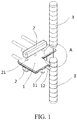
FIG. 1 is a perspective view of an assembling relationship of a secondary lithium battery, a fixture and a printing head in a method of edge sealing for a secondary lithium battery according to an embodiment of the present application; -
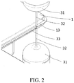
FIG. 2 is a partial enlarged view of section A in the method of edge sealing for a secondary lithium battery when the printing head is coating glue to a battery edge according to an embodiment of the present application; -
FIG. 3 is a side view of the assembling relationship of the secondary lithium battery, the fixture and the printing head in the method of edge sealing for the secondary lithium battery according to an embodiment of the present application; -
FIG. 4 is a partial enlarged side view of the assembling relationship of the secondary lithium battery, the fixture and the printing head in the method of edge sealing for the secondary lithium battery according to an embodiment of the present application; -
FIG. 5 is a schematic view of a section of the battery after single edge folding according to an embodiment of the present application; -
- 1-secondary lithium battery;
- 11-negative electrode tab;
- 12- positive electrode tab;
- 13-battery edge;
- 2-fixture;
- 21-sucker;
- 3-printing head;
- 31-gluing injector;
- 32-gluing needle;
- 33-edge sealing glue;
- 4-edge folding glue.
- In order to make the objectives, technical solutions and advantages of the present application more clear, the technical solutions of the present application will be clearly and completely described combining the embodiments and accompanying drawings of the present application, obviously, the embodiments described are merely a part of the embodiments of the present application, but not all of the embodiments. Based on the technical solutions and the embodiments provided by the present application, all other embodiments obtained by persons skilled in the art without any creative efforts shall belong to the protection scope of the present application.
- The expressions "front", "back", "left", "right", "top" and "bottom" mentioned in the disclosure are all referring to the placement states of the battery in the drawings.
- The method of edge sealing for a secondary lithium battery in the present application mainly including the following steps:
- (1) drawing a 3D model of a
battery edge 13 to be edge sealed of asecondary lithium battery 1, and inputting the 3D model into a 3D printer; - (2) positioning the
secondary lithium battery 1 to be edge sealed in a 3D printing area, fixing a relative position of thesecondary lithium battery 1 in the 3D printing area; - (3) stimulating, by the 3D printer, the
battery edge 13 according to the 3D model and setting a printing path; - (4) adding
edge sealing glue 33 in aprinting head 3 of the 3D printer, theprinting head 3 moves according to the set printing path and in the meantime performs at least one time of printing, so that printededge sealing glue 33 covers thebattery edge 13; - (5) solidifying the
edge sealing glue 33. - In the above solution, by combining the
edge gluing glue 33 and 3D printing, the 3D printer can stimulate the shape of thesecondary lithium battery 1 and make a fitted glue layer with the edge sealing glue of a specific viscosity, so as to guarantee that the edge of thesecondary lithium battery 1 with an irregular shape is covered by the glue, thereby achieving edge sealing and preventing aluminum exposure. - Devices involved in the above method of edge sealing mainly includes: a positioning and fixing apparatus, a 3D printer, a
printing head 3 of the 3D printer (gluing structure), and a secondary lithium battery 1 (including apositive electrode tab 12, anegative electrode tab 11 and a battery edge 13) packaged with a packaging bag, as shown inFIG.1 andFIG.3 . - In Step (1), a corresponding 3D model is drawn according to the size of the
battery edge 13. Usually, a 3D drawing software is selected to draw the 3D model of thebattery edge 13 and stimulate the edge of the outer package of thesecondary lithium battery 1. The 3D drawing software can be any drawing software, such as SolidWorks, ProE, Auto CAD, CATIA and so on. - Preferably, Step (1) further includes designing a suitable printing width according to the size of the
battery edge 13. - A needle with a suitable internal diameter is selected according to the designed printing width, and the gluing width of a single time of printing varies according to the different internal diameters of the needles; when the printing width is over too wide, at least twice of multiple times of printing can be adopted, that is, re-gluing along the same path, so as to guarantee effective covering of the battery edge.
- Taking the blue standard needle with an internal diameter of 0.41mm as an example, gluing with a single time of printing is adopted when the printing width is less than 500µm; and gluing with at least two times of printing is adopted when the printing width is more than 500µm, meantime guaranteeing that the glue bodies of the multiple times of printing evenly connects with each other.
- Preferably, before positioning the
secondary lithium battery 1 to be edge sealed in the 3D printing area, performing shaping and edge trimming to thesecondary lithium battery 1 to be edge sealed; according to the requirements on the size, cutting off excess aluminum plastic film sealing edge, of which the tolerance requirement can be appropriately adjusted according to requirements on the product; the manner of shaping and edge trimming can be cutting or punching. - Preferably, the shaping and edge trimming of the
secondary lithium battery 1 should guarantee that the trimmed edge is complete with no burrs, no ups and downs. - In Step (2), a
fixture 2 is adopted to fix and position thesecondary lithium battery 1 in the 3D printing area. - Preferably, a
fixture 2 that can provide vacuum pressure is adopted, as shown inFIG. 1 ,FIG. 2 andFIG. 4 , including a vacuum controlling chamber andmultiple suckers 21 connected with the vacuum controlling chamber. Thefixture 2 is symmetrically arranged on the two sides of the large plane of thesecondary lithium battery 1, of which thesuckers 21 act on the large plane of thesecondary lithium battery 1, the vacuum controlling chamber is evacuated to produce negative pressure, so that thesecondary lithium battery 1 is absorbed and fixed by thesuckers 21 on the two sides. - After positioning the
secondary lithium battery 1 in the 3D printing area, the relative positon of thesecondary lithium battery 1 in the 3D printing area is fixed, and then the 3D printer can use a charge coupled device (Charge Coupled Device, CCD) to search for the outer profile of thebattery edge 13 for path stimulation, or use a stored path program. Since the relative position of thesecondary lithium battery 1 of the same shape in the 3D printing area is fixed, the outer profile in the 3D printing area is identical either, thus only the outer profile of the firstsecondary lithium battery 1 needs to be stimulated to set the path. - As an improvement of the present application, as shown in
FIGs. 1-4 , theprinting head 3 includes a pair of gluinginjectors 31 provided with gluingneedles 32, the pair of gluinginjectors 31 is symmetrically arranged (symmetrically arranged up and down in the drawings), when printing, the gluing needles 32 of the pair of gluinginjectors 31 are respectively located close to the two sides of thebattery edge 13; after the selectededge sealing glue 33 is injected into the gluinginjectors 31, the two gluinginjectors 32 are controlled by a motion controlling device of the 3D printer and are provided with specific stable pressure, so as to move along the printing path with a same moving rate and a same glue extruding rate, and coat theedge sealing glue 33 on thebattery edge 13 from the gluing needles 32, so that glue of a uniform volume is left on the two sides of thebattery edge 13, thereby covering thebattery edge 13. - Preferably, the moving rate of the gluing
needle 32 is 5∼100mm/s; the glue extruding rate is 0.2-4 mm3/s. - Preferably, the internal diameter of the gluing
needle 32 is 0.21-1.43mm. - As an improvement of the present application, the viscosity of the
edge sealing glue 33 is 200 mPa·s ∼ 400 mPa·s. Glue with a too low viscosity will cause breakage of the liquid column, thus the glue is discontinuous, or a gap is formed after the liquid flows through the section thereby exposing the aluminum. Glue with a too high viscosity will cause decreasing of fluidity, thus the liquid cannot smoothly flow to the section and aluminum may be exposed in part of the section. In the meantime, for areas with narrow gluing slit, glue with a too high viscosity will cause the narrow slit to be completely blocked by the glue, resulting in potential risks in subsequent edge folding or applying. - As an improvement of the present application, the
edge sealing glue 33 used in Step (4) is light solidifying glue or heat solidifying glue. The light solidifying glue or heat solidifying glue can be completely solidified with a fast forming speed once entering into an ultraviolet light environment or a heat environment. In the mass production process, the solidifying speed will affect the efficiency of producing the secondary lithium battery in a unit interval, while other forming manners, such as low-temperature solidifying, may cause breakage or melting of the glue in the edge folding process or the edge ironing process, thereby causing the section protection lose efficacy. - The light solidifying glue is preferred to be UV light solidifying glue, for example acrylic resin adhesive. The main components of acrylic resin adhesive are acrylic resin, isobornylacrylate, hydroxyethyl acrylate and silicon dioxide, etc.
- Preferably, the heat solidifying glue is preferred to be acrylic adhesive.
- Preferably, the solidifying condition of the light solidifying glue is solidifying for 5∼10 seconds under ultraviolet light of 100∼500cd.
- Preferably, the solidifying condition of the heat solidifying glue is solidifying for 12∼20 minutes at 160°C∼180°C.
- As an improvement of the present application, the edge sealing process further includes a step of single edge folding: as shown in
FIG. 5 , coatingedge folding glue 4 on thebattery edge 13 coated with the solidifiededge sealing glue 33, and performing single edge folding when theedge folding glue 4 is half solidified, then fully solidifying theedge folding glue 4, so that the glued edge after the single edge folding will not break. - Preferably, the
edge folding glue 4 of the present application is anaerobic glue, including tetraethylene glycol dimethacrylate anaerobic glue, hydroxyethyl methylacrylate anaerobic glue, etc. -
- 1. The
secondary lithium battery 1 to be edge sealed packaged by a packaging bag is as shown inFIG. 1 , of which the large plane is L shaped; the width of thebattery edge 13 is 2.5mm, the designed width of thebattery edge 13 to be edge sealed is 0.4mm; firstly, adopting a 3D drawing software to draw a 3D model of thebattery edge 13 to be edge sealed, then inputting the 3D model into a 3D printer, and selecting a needle with the internal diameter of 0.41mm as the gluingneedle 32 of theprinting head 3; - 2. Trimming the edge with blades, cutting off excess aluminum plastic film sealing edge, so as to guarantee that the trimmed edge is complete with no burrs, no ups and downs;
- 3. Positioning the
secondary lithium battery 1 after shaping and edge trimming in the 3D printing area by afixture 2 with the large plane of thesecondary lithium battery 1 being horizontally placed, so that the relative position of thesecondary lithium battery 1 in the 3D printing area is fixed; - 4. Stimulating, by the 3D printer, the
battery edge 13 according to the aforementioned 3D model and setting the printing path; - 5. Injecting the acrylic resin UV light solidifying glue with a viscosity of 374mPa·s into the gluing
injector 31; starting printing, during which gluing needles 32 of the pair of gluinginjectors 31 are respectively located close to the two sides of thebattery edge 13, the motion controlling device of the printer simultaneously controls the motion of the two gluinginjectors 31 and provides the gluinginjectors 31 with specific stable pressure, so that the gluing needles 32 of the two gluinginjectors 31 simultaneously move along the trajectory of thebattery edge 13 with a same moving rate at 100mm/s and a same glue extruding rate at 4mm3/s according to the aforementioned printing path, and coating theedge sealing glue 33 on thebattery edge 13 from the gluing needles 32, so that glue of a uniform volume is left on the two sides of thebattery edge 13 to form a sealed structure covering thebattery edge 13; - 6. Carrying, by the
fixture 2, the edge sealedsecondary lithium battery 1 and entering into a UV light environment for glue solidifying for 7 seconds, so as to achieve fully solidifying; - 7. Coating hydroxyethyl methylacrylate anaerobic glue with good adhesive force on the
aforementioned battery edge 13 coated with the solidifiededge sealing glue 33, and performing a single edge folding process when the glue is half solidified, then fully solidifying theedge folding glue 33, so that the glued edge after the single edge folding will not break. - When performing edge sealing on a next secondary lithium battery with the same shape, it is only needed to put the
secondary lithium battery 1 to be edge sealed in thefixture 2 and then positioned and fixed, so that the nextsecondary lithium battery 1 can be printed with glue according to the same printing path with that of the firstsecondary lithium battery 1. If the shape of the nextsecondary lithium battery 1 is different from that of the aforementionedsecondary lithium battery 1, the above steps of the method of edge sealing should be repeated to print glue. -
- 1. The
secondary lithium battery 1 to be edge sealed packaged by a packaging bag is as shown inFIG. 1 , of which the large plane is L shaped; the width of thebattery edge 13 is 2.5mm, the designed width of thebattery edge 13 to be edge sealed is 0.4mm; firstly, adopting a 3D drawing software to draw a 3D model of thebattery edge 13 to be edge sealed, then inputting the 3D model into a 3D printer, and selecting a needle with the internal diameter of 0.41mm as the gluingneedle 32 of theprinting head 3; - 2. Trimming the edge with blades, cutting of excess aluminum plastic film sealing edge, so as to guarantee that the trimmed edge is complete with no burrs, no ups and downs;
- 3. Positioning the
secondary lithium battery 1 after shaping and edge trimming in the 3D printing area by afixture 2 with the large plane of thesecondary lithium battery 1 being horizontally placed, so that the relative position of thesecondary lithium battery 1 in the 3D printing area is fixed; - 4. Stimulating, by the 3D printer, the
battery edge 13 according to the aforementioned 3D model and setting the printing path; - 5. Injecting the acrylic resin UV light solidifying glue with a viscosity of 374mPa·s into the gluing
injector 31; performing two times of repeated glue printing, during which the moving rate of the gluinginjectors 31 is the same for each time of printing at 100mm/s, and the glue extruding rate is also the same for each time of printing at 4 mm3/s, the injecting needles on the two sides of thebattery edge 13 move simultaneously along the trajectory of the edge of a designed width and coat theedge sealing glue 33 on the width edge to be sealed from the injecting needles, so that glue of a uniform volume is formed on the two sides of thebattery edge 13, and at the outermost side of thebattery edge 13, the glue forms a sealed structure covering the trimmed section of thebattery edge 13; and the two times of glue printing are overlapped, so as to cover the battery edge more effectively; - 6. Carrying, by the
fixture 2, the edge sealedsecondary lithium battery 1 and entering into a UV light environment for glue solidifying for 7 seconds, so as to achieve fully solidifying; - 7. Coating hydroxyethyl methylacrylate anaerobic glue with good adhesive force on the
aforementioned battery edge 13 coated with the solidifiededge sealing glue 33, and performing a single edge folding process when the glue is half solidified, then fully solidifying theedge folding glue 33, so that the glued edge after the single edge folding will not break. - When performing edge sealing on a next secondary lithium battery with the same shape, it is only needed to put the
secondary lithium battery 1 to be edge sealed in thefixture 2 and then positioned and fixed, so that the nextsecondary lithium battery 1 can be printed with glue according to the same printing path with that of the firstsecondary lithium battery 1. If the shape of the nextsecondary lithium battery 1 is different from that of the aforementionedsecondary lithium battery 1, the above steps of the method of edge sealing should be repeated to print glue. - The present application is disclosed with the preferred embodiments as above, which are not used to limit the claims; any person skilled in the art, within the conception of the present application, can make a variety of possible variations and modifications, therefore the protection scope of the present application shall be subjected to the scope defined by the claims of the present application.
Claims (10)
- A method of edge sealing for a secondary lithium battery, characterized in that, comprising steps of:(1) drawing a 3D model of a battery edge to be edge sealed of a secondary lithium battery, and inputting the 3D model into a 3D printer;(2) positioning the secondary lithium battery to be edge sealed in a 3D printing area, and fixing a relative position of the secondary lithium battery in the 3D printing area;(3) stimulating, by the 3D printer, the battery edge according to the 3D model and setting a printing path;(4) adding edge sealing glue in a printing head of the 3D printer, the printing head moves according to the set printing path and in the meantime performs at least one time of printing, so that printed edge sealing glue covers the battery edge;(5) solidifying the edge sealing glue.
- The method of edge sealing according to claim 1, characterized in that, step (1) further comprises setting a printing width according to a size of the battery edge.
- The method of edge sealing according to claim 1, characterized in that, before positioning the secondary lithium battery to be edge sealed in the 3D printing area, further comprises shaping and edge trimming the battery edge of the secondary lithium battery.
- The method of edge sealing according to claim 1, characterized in that, in step (4), the printing head comprises a pair of symmetrically arranged gluing injectors provided with gluing needles, when printing, the gluing needles of the pair of gluing injectors are respectively located close to two sides of the battery edge, and simultaneously move along the printing path with a same moving rate and a same glue extruding rate, and print glue of a uniform volume on the two sides of the battery edge.
- The method of edge sealing according to claim 4, characterized in that, the moving rate of the gluing needles is 5∼100mm/s; the glue extruding rate is 0.2-4 mm3/s.
- The method of edge sealing according to claim 1, characterized in that, a viscosity of the edge sealing glue is 200 mPa·s ∼ 400 mPa·s.
- The method of edge sealing according to claim 1, characterized in that, the edge sealing glue is light solidifying glue or heat solidifying glue; the light solidifying glue is preferably UV light solidifying glue, further preferably acrylic resin adhesive; the heat solidifying glue is preferably acrylic adhesive.
- The method of edge sealing according to claim 7, characterized in that, a solidifying condition of the light solidifying glue is solidifying for 5∼10 seconds under ultraviolet light of 100∼500cd; a solidifying condition of the heat solidifying glue is solidifying for 12∼20 minutes at 160°C∼180°C.
- The method of edge sealing according to claim 1, characterized in that, after accomplishing step (5), further comprises coating edge folding glue on the battery edge coated with the solidified edge sealing glue, and performing single edge folding when the edge folding glue is half solidified, then fully solidifying the edge folding glue.
- The method of edge sealing according to claim 9, characterized in that, the edge folding glue is anaerobic glue, preferably tetraethylene glycol dimethacrylate anaerobic glue or hydroxyethyl methylacrylate anaerobic glue.
Applications Claiming Priority (1)
| Application Number | Priority Date | Filing Date | Title |
|---|---|---|---|
| CN201610244262.1A CN105826612B (en) | 2016-04-19 | 2016-04-19 | A kind of edge sealing method of secondary lithium battery |
Publications (2)
| Publication Number | Publication Date |
|---|---|
| EP3236509A1 true EP3236509A1 (en) | 2017-10-25 |
| EP3236509B1 EP3236509B1 (en) | 2020-04-15 |
Family
ID=56527106
Family Applications (1)
| Application Number | Title | Priority Date | Filing Date |
|---|---|---|---|
| EP16196263.4A Active EP3236509B1 (en) | 2016-04-19 | 2016-10-28 | Method of edge sealing for secondary lithium battery |
Country Status (5)
| Country | Link |
|---|---|
| US (1) | US10166723B2 (en) |
| EP (1) | EP3236509B1 (en) |
| JP (1) | JP6348949B2 (en) |
| CN (1) | CN105826612B (en) |
| ES (1) | ES2804724T3 (en) |
Cited By (1)
| Publication number | Priority date | Publication date | Assignee | Title |
|---|---|---|---|---|
| CN113829685A (en) * | 2021-09-13 | 2021-12-24 | 深圳市鸿富诚屏蔽材料有限公司 | A kind of graphene thermal conductive gasket wrapping process and wrapping graphene thermal conductive gasket |
Families Citing this family (13)
| Publication number | Priority date | Publication date | Assignee | Title |
|---|---|---|---|---|
| WO2018049573A1 (en) * | 2016-09-13 | 2018-03-22 | 东莞新能源科技有限公司 | Battery cell periphery sealing process, and battery cell periphery sealing treatment device |
| WO2018076334A1 (en) * | 2016-10-31 | 2018-05-03 | 东莞新能源科技有限公司 | Cell edge encapsulation apparatus |
| CN106450473B (en) * | 2016-11-07 | 2018-10-12 | 东莞市腾威电子材料技术有限公司 | The packaging technology of dynamic lithium battery module |
| CN106803610B (en) * | 2017-01-17 | 2019-06-18 | 华霆(合肥)动力技术有限公司 | A kind of manufacturing method and heat management device of heat management device |
| CN107953556A (en) * | 2017-12-18 | 2018-04-24 | 福建铁工机智能机器人有限公司 | A kind of device and method for installing adhesive tape for refrigerator doors using 3D printing |
| CN109193034A (en) * | 2018-08-28 | 2019-01-11 | 陕西中丰新能源有限公司 | A kind of 96 series-parallel chemical synthesis technologies of 18650 battery |
| KR102363976B1 (en) * | 2018-11-20 | 2022-02-17 | 주식회사 엘지에너지솔루션 | The Apparatus And The Method For Applying Glue |
| CN110212252B (en) * | 2019-07-02 | 2024-06-21 | 博众精工科技股份有限公司 | Rubber coating machine |
| CN111063938A (en) * | 2019-12-05 | 2020-04-24 | 惠州锂威新能源科技有限公司 | A new hemming process for two-sealing process |
| CN111403812B (en) * | 2020-03-06 | 2022-08-19 | 惠州锂威新能源科技有限公司 | Edge sealing optimization process |
| CN112952207B (en) * | 2021-03-03 | 2022-07-01 | 芜湖天弋能源科技有限公司 | Soft package lithium ion battery cell packaging method |
| CN115555220A (en) * | 2022-03-30 | 2023-01-03 | 四川英诺维新材料科技有限公司 | Secondary sealing protection method for vacuum glass |
| CN120357043B (en) * | 2025-06-20 | 2025-10-31 | 重庆长安汽车股份有限公司 | Battery cell, packaging method thereof, packaging system, solid-state battery and hot-melt resin material |
Citations (4)
| Publication number | Priority date | Publication date | Assignee | Title |
|---|---|---|---|---|
| US20020155349A1 (en) * | 2001-04-19 | 2002-10-24 | Michael Cheiky | Battery case with edge seal |
| CN201862534U (en) * | 2010-11-19 | 2011-06-15 | 哈尔滨光宇电源股份有限公司 | Automatic glue dispenser of square lithium ion battery |
| EP2535961A1 (en) * | 2011-06-16 | 2012-12-19 | SK Innovation Co. Ltd. | Pouch type secondary battery and method for manufacturing the same |
| EP2685517A1 (en) * | 2012-07-10 | 2014-01-15 | Dongguan Amperex Technology Limited | A soft-package lithium battery edge fold structure |
Family Cites Families (13)
| Publication number | Priority date | Publication date | Assignee | Title |
|---|---|---|---|---|
| JPH07124653A (en) | 1993-10-28 | 1995-05-16 | Torai Eng Kk | Combined working type hemming device |
| JP2003168245A (en) * | 2001-11-30 | 2003-06-13 | Fuji Photo Film Co Ltd | Optical information recording medium |
| CN101632979B (en) * | 2009-08-09 | 2011-07-27 | 江苏新源动力有限公司 | Method for bonding and gluing bipolar plate |
| GB2477552B (en) * | 2010-02-08 | 2016-01-27 | Qinetiq Ltd | Thin electrochemical cell |
| CN202134624U (en) * | 2011-06-10 | 2012-02-01 | 东莞新能源科技有限公司 | Flexible packaging lithium battery edge sealing structure |
| JP5831791B2 (en) * | 2011-08-23 | 2015-12-09 | コニカミノルタ株式会社 | Three-dimensional object forming apparatus and three-dimensional object forming method |
| US9963597B2 (en) * | 2012-07-12 | 2018-05-08 | President And Fellows Of Harvard College | Slippery self-lubricating polymer surfaces |
| US20150197063A1 (en) * | 2014-01-12 | 2015-07-16 | Zohar SHINAR | Device, method, and system of three-dimensional printing |
| JP2015168803A (en) * | 2014-03-10 | 2015-09-28 | 日立化成株式会社 | Conductive adhesive composition, connector, solar cell module and method for producing the same |
| JP2015185416A (en) * | 2014-03-25 | 2015-10-22 | 凸版印刷株式会社 | lithium ion secondary battery |
| CN104161353B (en) * | 2014-07-31 | 2015-11-11 | 黑金刚(福建)自动化科技股份公司 | A kind of automation glue spraying equipment of vamp and automatic glue-spraying method |
| CN204156022U (en) * | 2014-10-17 | 2015-02-11 | 惠州市惠德瑞锂电科技有限公司 | A kind of rubber-coated mechanism of lithium battery |
| CN105342070A (en) * | 2015-09-25 | 2016-02-24 | 东莞市奇峰液压科技有限公司 | Three-dimensional shoe sole cementing method and three-dimensional shoe sole cementing device |
-
2016
- 2016-04-19 CN CN201610244262.1A patent/CN105826612B/en active Active
- 2016-10-20 US US15/299,089 patent/US10166723B2/en active Active
- 2016-10-28 ES ES16196263T patent/ES2804724T3/en active Active
- 2016-10-28 EP EP16196263.4A patent/EP3236509B1/en active Active
- 2016-11-14 JP JP2016221837A patent/JP6348949B2/en active Active
Patent Citations (4)
| Publication number | Priority date | Publication date | Assignee | Title |
|---|---|---|---|---|
| US20020155349A1 (en) * | 2001-04-19 | 2002-10-24 | Michael Cheiky | Battery case with edge seal |
| CN201862534U (en) * | 2010-11-19 | 2011-06-15 | 哈尔滨光宇电源股份有限公司 | Automatic glue dispenser of square lithium ion battery |
| EP2535961A1 (en) * | 2011-06-16 | 2012-12-19 | SK Innovation Co. Ltd. | Pouch type secondary battery and method for manufacturing the same |
| EP2685517A1 (en) * | 2012-07-10 | 2014-01-15 | Dongguan Amperex Technology Limited | A soft-package lithium battery edge fold structure |
Non-Patent Citations (1)
| Title |
|---|
| ADRIANO AMBROSI ET AL: "3D-printing technologies for electrochemical applications", CHEMICAL SOCIETY REVIEWS., vol. 45, no. 10, 6 April 2016 (2016-04-06), GB, pages 2740 - 2755, XP055346582, ISSN: 0306-0012, DOI: 10.1039/C5CS00714C * |
Cited By (2)
| Publication number | Priority date | Publication date | Assignee | Title |
|---|---|---|---|---|
| CN113829685A (en) * | 2021-09-13 | 2021-12-24 | 深圳市鸿富诚屏蔽材料有限公司 | A kind of graphene thermal conductive gasket wrapping process and wrapping graphene thermal conductive gasket |
| CN113829685B (en) * | 2021-09-13 | 2023-12-22 | 深圳市鸿富诚新材料股份有限公司 | Graphene heat conduction gasket edge covering process and edge covering graphene heat conduction gasket |
Also Published As
| Publication number | Publication date |
|---|---|
| US20170297269A1 (en) | 2017-10-19 |
| CN105826612A (en) | 2016-08-03 |
| EP3236509B1 (en) | 2020-04-15 |
| JP6348949B2 (en) | 2018-06-27 |
| ES2804724T3 (en) | 2021-02-09 |
| US10166723B2 (en) | 2019-01-01 |
| JP2017195171A (en) | 2017-10-26 |
| CN105826612B (en) | 2019-04-05 |
Similar Documents
| Publication | Publication Date | Title |
|---|---|---|
| US10166723B2 (en) | Method of edge sealing for secondary lithium battery | |
| WO2018049571A1 (en) | Periphery sealing device for battery cell | |
| CN104536212B (en) | Liquid crystal display device, liquid crystal display panel motherboard and preparation method thereof | |
| CN112421088A (en) | Battery pack manufacturing method | |
| CN108448012A (en) | All-colour LED display module and its packaging method and display screen | |
| CN105390570B (en) | A kind of manufacture method of LED encapsulation structure | |
| US9612481B2 (en) | Display substrate, method for manufacturing the same, and liquid crystal display device | |
| WO2017193582A1 (en) | Packaging structure for surface acoustic wave filter chip | |
| CN106384105A (en) | Manufacturing method of fingerprint recognition module | |
| CN109031836B (en) | ITO glass conducting layer segmentation method and ITO conducting glass | |
| CN108987789A (en) | A kind of method and battery adjusting core elasticity | |
| CN112259661B (en) | A potting device, LED display screen and packaging method thereof | |
| CN103367529B (en) | A kind of Overflow-glue sealing manufacturing method for photovoltaic assembly | |
| CN106842593A (en) | The preparation method of 2D/3D switchable display devices | |
| CN105199615B (en) | For method, structure and the device for being combined two substrates | |
| CN114220896A (en) | Flip chip packaging process and flip chip packaging structure | |
| CN104332416A (en) | Preparation method of flexible display and flexible display | |
| CN208955024U (en) | A kind of polymer Li-ion battery | |
| CN101872100A (en) | Electronic ink display and manufacturing method thereof | |
| CN108605064B (en) | A packaging method, packaging device and terminal | |
| CN105629531B (en) | Spit the coating method of glue spray head and sealant | |
| CN114069052B (en) | Battery cell packaging method and battery preparation method | |
| CN115373190A (en) | Filling method, preparation method and application of electrochromic solution in electrochromic device | |
| CN208847986U (en) | A kind of spectacle lens | |
| CN206587957U (en) | A kind of spraying frock structure of rubber |
Legal Events
| Date | Code | Title | Description |
|---|---|---|---|
| PUAI | Public reference made under article 153(3) epc to a published international application that has entered the european phase |
Free format text: ORIGINAL CODE: 0009012 |
|
| STAA | Information on the status of an ep patent application or granted ep patent |
Free format text: STATUS: REQUEST FOR EXAMINATION WAS MADE |
|
| 17P | Request for examination filed |
Effective date: 20161028 |
|
| AK | Designated contracting states |
Kind code of ref document: A1 Designated state(s): AL AT BE BG CH CY CZ DE DK EE ES FI FR GB GR HR HU IE IS IT LI LT LU LV MC MK MT NL NO PL PT RO RS SE SI SK SM TR |
|
| AX | Request for extension of the european patent |
Extension state: BA ME |
|
| STAA | Information on the status of an ep patent application or granted ep patent |
Free format text: STATUS: EXAMINATION IS IN PROGRESS |
|
| 17Q | First examination report despatched |
Effective date: 20180828 |
|
| GRAP | Despatch of communication of intention to grant a patent |
Free format text: ORIGINAL CODE: EPIDOSNIGR1 |
|
| STAA | Information on the status of an ep patent application or granted ep patent |
Free format text: STATUS: GRANT OF PATENT IS INTENDED |
|
| RIC1 | Information provided on ipc code assigned before grant |
Ipc: H01M 2/08 20060101ALI20191015BHEP Ipc: H01M 10/0525 20100101ALI20191015BHEP Ipc: H01M 2/04 20060101AFI20191015BHEP Ipc: B29C 64/112 20170101ALI20191015BHEP |
|
| INTG | Intention to grant announced |
Effective date: 20191107 |
|
| GRAS | Grant fee paid |
Free format text: ORIGINAL CODE: EPIDOSNIGR3 |
|
| GRAA | (expected) grant |
Free format text: ORIGINAL CODE: 0009210 |
|
| STAA | Information on the status of an ep patent application or granted ep patent |
Free format text: STATUS: THE PATENT HAS BEEN GRANTED |
|
| AK | Designated contracting states |
Kind code of ref document: B1 Designated state(s): AL AT BE BG CH CY CZ DE DK EE ES FI FR GB GR HR HU IE IS IT LI LT LU LV MC MK MT NL NO PL PT RO RS SE SI SK SM TR |
|
| REG | Reference to a national code |
Ref country code: CH Ref legal event code: EP |
|
| REG | Reference to a national code |
Ref country code: DE Ref legal event code: R096 Ref document number: 602016033960 Country of ref document: DE |
|
| REG | Reference to a national code |
Ref country code: IE Ref legal event code: FG4D |
|
| REG | Reference to a national code |
Ref country code: AT Ref legal event code: REF Ref document number: 1258333 Country of ref document: AT Kind code of ref document: T Effective date: 20200515 |
|
| REG | Reference to a national code |
Ref country code: NL Ref legal event code: MP Effective date: 20200415 |
|
| REG | Reference to a national code |
Ref country code: LT Ref legal event code: MG4D |
|
| PG25 | Lapsed in a contracting state [announced via postgrant information from national office to epo] |
Ref country code: LT Free format text: LAPSE BECAUSE OF FAILURE TO SUBMIT A TRANSLATION OF THE DESCRIPTION OR TO PAY THE FEE WITHIN THE PRESCRIBED TIME-LIMIT Effective date: 20200415 Ref country code: NL Free format text: LAPSE BECAUSE OF FAILURE TO SUBMIT A TRANSLATION OF THE DESCRIPTION OR TO PAY THE FEE WITHIN THE PRESCRIBED TIME-LIMIT Effective date: 20200415 Ref country code: PT Free format text: LAPSE BECAUSE OF FAILURE TO SUBMIT A TRANSLATION OF THE DESCRIPTION OR TO PAY THE FEE WITHIN THE PRESCRIBED TIME-LIMIT Effective date: 20200817 Ref country code: FI Free format text: LAPSE BECAUSE OF FAILURE TO SUBMIT A TRANSLATION OF THE DESCRIPTION OR TO PAY THE FEE WITHIN THE PRESCRIBED TIME-LIMIT Effective date: 20200415 Ref country code: GR Free format text: LAPSE BECAUSE OF FAILURE TO SUBMIT A TRANSLATION OF THE DESCRIPTION OR TO PAY THE FEE WITHIN THE PRESCRIBED TIME-LIMIT Effective date: 20200716 Ref country code: IS Free format text: LAPSE BECAUSE OF FAILURE TO SUBMIT A TRANSLATION OF THE DESCRIPTION OR TO PAY THE FEE WITHIN THE PRESCRIBED TIME-LIMIT Effective date: 20200815 Ref country code: NO Free format text: LAPSE BECAUSE OF FAILURE TO SUBMIT A TRANSLATION OF THE DESCRIPTION OR TO PAY THE FEE WITHIN THE PRESCRIBED TIME-LIMIT Effective date: 20200715 Ref country code: SE Free format text: LAPSE BECAUSE OF FAILURE TO SUBMIT A TRANSLATION OF THE DESCRIPTION OR TO PAY THE FEE WITHIN THE PRESCRIBED TIME-LIMIT Effective date: 20200415 |
|
| REG | Reference to a national code |
Ref country code: AT Ref legal event code: MK05 Ref document number: 1258333 Country of ref document: AT Kind code of ref document: T Effective date: 20200415 |
|
| REG | Reference to a national code |
Ref country code: DE Ref legal event code: R079 Ref document number: 602016033960 Country of ref document: DE Free format text: PREVIOUS MAIN CLASS: H01M0002040000 Ipc: H01M0050147000 |
|
| PG25 | Lapsed in a contracting state [announced via postgrant information from national office to epo] |
Ref country code: HR Free format text: LAPSE BECAUSE OF FAILURE TO SUBMIT A TRANSLATION OF THE DESCRIPTION OR TO PAY THE FEE WITHIN THE PRESCRIBED TIME-LIMIT Effective date: 20200415 Ref country code: RS Free format text: LAPSE BECAUSE OF FAILURE TO SUBMIT A TRANSLATION OF THE DESCRIPTION OR TO PAY THE FEE WITHIN THE PRESCRIBED TIME-LIMIT Effective date: 20200415 Ref country code: BG Free format text: LAPSE BECAUSE OF FAILURE TO SUBMIT A TRANSLATION OF THE DESCRIPTION OR TO PAY THE FEE WITHIN THE PRESCRIBED TIME-LIMIT Effective date: 20200715 Ref country code: LV Free format text: LAPSE BECAUSE OF FAILURE TO SUBMIT A TRANSLATION OF THE DESCRIPTION OR TO PAY THE FEE WITHIN THE PRESCRIBED TIME-LIMIT Effective date: 20200415 |
|
| PG25 | Lapsed in a contracting state [announced via postgrant information from national office to epo] |
Ref country code: AL Free format text: LAPSE BECAUSE OF FAILURE TO SUBMIT A TRANSLATION OF THE DESCRIPTION OR TO PAY THE FEE WITHIN THE PRESCRIBED TIME-LIMIT Effective date: 20200415 |
|
| REG | Reference to a national code |
Ref country code: DE Ref legal event code: R097 Ref document number: 602016033960 Country of ref document: DE |
|
| PG25 | Lapsed in a contracting state [announced via postgrant information from national office to epo] |
Ref country code: RO Free format text: LAPSE BECAUSE OF FAILURE TO SUBMIT A TRANSLATION OF THE DESCRIPTION OR TO PAY THE FEE WITHIN THE PRESCRIBED TIME-LIMIT Effective date: 20200415 Ref country code: CZ Free format text: LAPSE BECAUSE OF FAILURE TO SUBMIT A TRANSLATION OF THE DESCRIPTION OR TO PAY THE FEE WITHIN THE PRESCRIBED TIME-LIMIT Effective date: 20200415 Ref country code: DK Free format text: LAPSE BECAUSE OF FAILURE TO SUBMIT A TRANSLATION OF THE DESCRIPTION OR TO PAY THE FEE WITHIN THE PRESCRIBED TIME-LIMIT Effective date: 20200415 Ref country code: SM Free format text: LAPSE BECAUSE OF FAILURE TO SUBMIT A TRANSLATION OF THE DESCRIPTION OR TO PAY THE FEE WITHIN THE PRESCRIBED TIME-LIMIT Effective date: 20200415 Ref country code: AT Free format text: LAPSE BECAUSE OF FAILURE TO SUBMIT A TRANSLATION OF THE DESCRIPTION OR TO PAY THE FEE WITHIN THE PRESCRIBED TIME-LIMIT Effective date: 20200415 Ref country code: EE Free format text: LAPSE BECAUSE OF FAILURE TO SUBMIT A TRANSLATION OF THE DESCRIPTION OR TO PAY THE FEE WITHIN THE PRESCRIBED TIME-LIMIT Effective date: 20200415 |
|
| REG | Reference to a national code |
Ref country code: ES Ref legal event code: FG2A Ref document number: 2804724 Country of ref document: ES Kind code of ref document: T3 Effective date: 20210209 |
|
| PLBE | No opposition filed within time limit |
Free format text: ORIGINAL CODE: 0009261 |
|
| STAA | Information on the status of an ep patent application or granted ep patent |
Free format text: STATUS: NO OPPOSITION FILED WITHIN TIME LIMIT |
|
| PG25 | Lapsed in a contracting state [announced via postgrant information from national office to epo] |
Ref country code: SK Free format text: LAPSE BECAUSE OF FAILURE TO SUBMIT A TRANSLATION OF THE DESCRIPTION OR TO PAY THE FEE WITHIN THE PRESCRIBED TIME-LIMIT Effective date: 20200415 Ref country code: PL Free format text: LAPSE BECAUSE OF FAILURE TO SUBMIT A TRANSLATION OF THE DESCRIPTION OR TO PAY THE FEE WITHIN THE PRESCRIBED TIME-LIMIT Effective date: 20200415 |
|
| 26N | No opposition filed |
Effective date: 20210118 |
|
| PG25 | Lapsed in a contracting state [announced via postgrant information from national office to epo] |
Ref country code: SI Free format text: LAPSE BECAUSE OF FAILURE TO SUBMIT A TRANSLATION OF THE DESCRIPTION OR TO PAY THE FEE WITHIN THE PRESCRIBED TIME-LIMIT Effective date: 20200415 |
|
| REG | Reference to a national code |
Ref country code: CH Ref legal event code: PL |
|
| PG25 | Lapsed in a contracting state [announced via postgrant information from national office to epo] |
Ref country code: LU Free format text: LAPSE BECAUSE OF NON-PAYMENT OF DUE FEES Effective date: 20201028 Ref country code: MC Free format text: LAPSE BECAUSE OF FAILURE TO SUBMIT A TRANSLATION OF THE DESCRIPTION OR TO PAY THE FEE WITHIN THE PRESCRIBED TIME-LIMIT Effective date: 20200415 |
|
| REG | Reference to a national code |
Ref country code: BE Ref legal event code: MM Effective date: 20201031 |
|
| PG25 | Lapsed in a contracting state [announced via postgrant information from national office to epo] |
Ref country code: LI Free format text: LAPSE BECAUSE OF NON-PAYMENT OF DUE FEES Effective date: 20201031 Ref country code: CH Free format text: LAPSE BECAUSE OF NON-PAYMENT OF DUE FEES Effective date: 20201031 Ref country code: BE Free format text: LAPSE BECAUSE OF NON-PAYMENT OF DUE FEES Effective date: 20201031 |
|
| PG25 | Lapsed in a contracting state [announced via postgrant information from national office to epo] |
Ref country code: IE Free format text: LAPSE BECAUSE OF NON-PAYMENT OF DUE FEES Effective date: 20201028 |
|
| PG25 | Lapsed in a contracting state [announced via postgrant information from national office to epo] |
Ref country code: TR Free format text: LAPSE BECAUSE OF FAILURE TO SUBMIT A TRANSLATION OF THE DESCRIPTION OR TO PAY THE FEE WITHIN THE PRESCRIBED TIME-LIMIT Effective date: 20200415 Ref country code: MT Free format text: LAPSE BECAUSE OF FAILURE TO SUBMIT A TRANSLATION OF THE DESCRIPTION OR TO PAY THE FEE WITHIN THE PRESCRIBED TIME-LIMIT Effective date: 20200415 Ref country code: CY Free format text: LAPSE BECAUSE OF FAILURE TO SUBMIT A TRANSLATION OF THE DESCRIPTION OR TO PAY THE FEE WITHIN THE PRESCRIBED TIME-LIMIT Effective date: 20200415 |
|
| PG25 | Lapsed in a contracting state [announced via postgrant information from national office to epo] |
Ref country code: MK Free format text: LAPSE BECAUSE OF FAILURE TO SUBMIT A TRANSLATION OF THE DESCRIPTION OR TO PAY THE FEE WITHIN THE PRESCRIBED TIME-LIMIT Effective date: 20200415 |
|
| P01 | Opt-out of the competence of the unified patent court (upc) registered |
Effective date: 20230601 |
|
| PGFP | Annual fee paid to national office [announced via postgrant information from national office to epo] |
Ref country code: IT Payment date: 20250926 Year of fee payment: 10 |
|
| PGFP | Annual fee paid to national office [announced via postgrant information from national office to epo] |
Ref country code: GB Payment date: 20250911 Year of fee payment: 10 |
|
| PGFP | Annual fee paid to national office [announced via postgrant information from national office to epo] |
Ref country code: FR Payment date: 20250922 Year of fee payment: 10 |
|
| PGFP | Annual fee paid to national office [announced via postgrant information from national office to epo] |
Ref country code: DE Payment date: 20250916 Year of fee payment: 10 |
|
| PGFP | Annual fee paid to national office [announced via postgrant information from national office to epo] |
Ref country code: ES Payment date: 20251104 Year of fee payment: 10 |