EP3235553B1 - Élément filtrant - Google Patents
Élément filtrant Download PDFInfo
- Publication number
- EP3235553B1 EP3235553B1 EP17170047.9A EP17170047A EP3235553B1 EP 3235553 B1 EP3235553 B1 EP 3235553B1 EP 17170047 A EP17170047 A EP 17170047A EP 3235553 B1 EP3235553 B1 EP 3235553B1
- Authority
- EP
- European Patent Office
- Prior art keywords
- end cap
- bowl
- filter element
- filter
- indexing structure
- Prior art date
- Legal status (The legal status is an assumption and is not a legal conclusion. Google has not performed a legal analysis and makes no representation as to the accuracy of the status listed.)
- Active
Links
- 239000011800 void material Substances 0.000 claims description 12
- 239000012530 fluid Substances 0.000 claims description 10
- 230000000295 complement effect Effects 0.000 claims description 7
- 239000000463 material Substances 0.000 claims description 6
- 238000004891 communication Methods 0.000 claims description 2
- 230000002093 peripheral effect Effects 0.000 claims 2
- 239000000446 fuel Substances 0.000 description 27
- XLYOFNOQVPJJNP-UHFFFAOYSA-N water Substances O XLYOFNOQVPJJNP-UHFFFAOYSA-N 0.000 description 10
- 238000002485 combustion reaction Methods 0.000 description 7
- 238000001914 filtration Methods 0.000 description 6
- 230000000712 assembly Effects 0.000 description 5
- 238000000429 assembly Methods 0.000 description 5
- 239000002283 diesel fuel Substances 0.000 description 5
- 230000013011 mating Effects 0.000 description 5
- 239000011159 matrix material Substances 0.000 description 5
- 238000002347 injection Methods 0.000 description 4
- 239000007924 injection Substances 0.000 description 4
- 239000002245 particle Substances 0.000 description 4
- 210000004907 gland Anatomy 0.000 description 3
- 239000004033 plastic Substances 0.000 description 3
- 239000002699 waste material Substances 0.000 description 3
- 238000009825 accumulation Methods 0.000 description 2
- 230000007613 environmental effect Effects 0.000 description 2
- 238000012423 maintenance Methods 0.000 description 2
- 239000002991 molded plastic Substances 0.000 description 2
- 239000010802 sludge Substances 0.000 description 2
- 229910000831 Steel Inorganic materials 0.000 description 1
- 239000000853 adhesive Substances 0.000 description 1
- 230000001070 adhesive effect Effects 0.000 description 1
- 230000002411 adverse Effects 0.000 description 1
- 229910052782 aluminium Inorganic materials 0.000 description 1
- XAGFODPZIPBFFR-UHFFFAOYSA-N aluminium Chemical compound [Al] XAGFODPZIPBFFR-UHFFFAOYSA-N 0.000 description 1
- 239000002131 composite material Substances 0.000 description 1
- 238000010276 construction Methods 0.000 description 1
- 238000005260 corrosion Methods 0.000 description 1
- 230000007797 corrosion Effects 0.000 description 1
- 230000009977 dual effect Effects 0.000 description 1
- 230000000694 effects Effects 0.000 description 1
- 239000000835 fiber Substances 0.000 description 1
- 230000008014 freezing Effects 0.000 description 1
- 238000007710 freezing Methods 0.000 description 1
- 238000007689 inspection Methods 0.000 description 1
- 238000009434 installation Methods 0.000 description 1
- 238000004519 manufacturing process Methods 0.000 description 1
- 229910052751 metal Inorganic materials 0.000 description 1
- 239000002184 metal Substances 0.000 description 1
- 238000000034 method Methods 0.000 description 1
- 238000012986 modification Methods 0.000 description 1
- 230000004048 modification Effects 0.000 description 1
- 239000013618 particulate matter Substances 0.000 description 1
- 239000011148 porous material Substances 0.000 description 1
- 238000003908 quality control method Methods 0.000 description 1
- 238000004064 recycling Methods 0.000 description 1
- 238000000926 separation method Methods 0.000 description 1
- 239000000243 solution Substances 0.000 description 1
- 239000010959 steel Substances 0.000 description 1
- 238000006467 substitution reaction Methods 0.000 description 1
Images


Classifications
-
- B—PERFORMING OPERATIONS; TRANSPORTING
- B01—PHYSICAL OR CHEMICAL PROCESSES OR APPARATUS IN GENERAL
- B01D—SEPARATION
- B01D29/00—Filters with filtering elements stationary during filtration, e.g. pressure or suction filters, not covered by groups B01D24/00 - B01D27/00; Filtering elements therefor
- B01D29/11—Filters with filtering elements stationary during filtration, e.g. pressure or suction filters, not covered by groups B01D24/00 - B01D27/00; Filtering elements therefor with bag, cage, hose, tube, sleeve or like filtering elements
- B01D29/13—Supported filter elements
- B01D29/15—Supported filter elements arranged for inward flow filtration
- B01D29/21—Supported filter elements arranged for inward flow filtration with corrugated, folded or wound sheets
-
- B—PERFORMING OPERATIONS; TRANSPORTING
- B01—PHYSICAL OR CHEMICAL PROCESSES OR APPARATUS IN GENERAL
- B01D—SEPARATION
- B01D29/00—Filters with filtering elements stationary during filtration, e.g. pressure or suction filters, not covered by groups B01D24/00 - B01D27/00; Filtering elements therefor
- B01D29/96—Filters with filtering elements stationary during filtration, e.g. pressure or suction filters, not covered by groups B01D24/00 - B01D27/00; Filtering elements therefor in which the filtering elements are moved between filtering operations; Particular measures for removing or replacing the filtering elements; Transport systems for filters
-
- B—PERFORMING OPERATIONS; TRANSPORTING
- B01—PHYSICAL OR CHEMICAL PROCESSES OR APPARATUS IN GENERAL
- B01D—SEPARATION
- B01D2201/00—Details relating to filtering apparatus
- B01D2201/29—Filter cartridge constructions
- B01D2201/291—End caps
- B01D2201/295—End caps with projections extending in a radial outward direction, e.g. for use as a guide, spacing means
-
- B—PERFORMING OPERATIONS; TRANSPORTING
- B01—PHYSICAL OR CHEMICAL PROCESSES OR APPARATUS IN GENERAL
- B01D—SEPARATION
- B01D2201/00—Details relating to filtering apparatus
- B01D2201/29—Filter cartridge constructions
- B01D2201/291—End caps
- B01D2201/296—Other than having a circular shape
-
- B—PERFORMING OPERATIONS; TRANSPORTING
- B01—PHYSICAL OR CHEMICAL PROCESSES OR APPARATUS IN GENERAL
- B01D—SEPARATION
- B01D2201/00—Details relating to filtering apparatus
- B01D2201/40—Special measures for connecting different parts of the filter
- B01D2201/4046—Means for avoiding false mounting of different parts
-
- B—PERFORMING OPERATIONS; TRANSPORTING
- B01—PHYSICAL OR CHEMICAL PROCESSES OR APPARATUS IN GENERAL
- B01D—SEPARATION
- B01D2201/00—Details relating to filtering apparatus
- B01D2201/40—Special measures for connecting different parts of the filter
- B01D2201/4076—Anti-rotational means
Definitions
- This application relates generally to filter assemblies employed in connection with internal combustion engines. More particularly, the present application relates to filter assemblies having a replaceable filter element for removing foreign particles and/or separating water from fuel of the fuel supply system of an internal combustion engine.
- a number of conventional fuel filter systems perform the dual functions of removing particulate matter from the diesel fuel and separating water from the fuel.
- Prior art fuel filters have typically been constructed in the form of a metal can, permanently enclosing the filter element in a single use assembly. While these assemblies have proved to be effective and reliable, they are less than ideal in terms of waste of materials and disposal cost.
- the filter cartridge surrounds and supports a filter element typically constructed of an accordion folded (pleated, cylindrical arrangement of filter media, which is usually a paper-like composite of selected fibers, chemically treated to reject water.
- the pleated cylinder of filter media is typically secured to end caps at each end by adhesive or the like, forcing fluid through the filter media before flowing on to the fuel handling systems.
- the disposable filter cartridge is replaced at preestablished intervals of filter usage.
- the filter cartridge requirements may vary depending upon such characteristics as the type and make of the internal combustion engine, the specific applications for which the engine is employed, the climate in which the combustion engine is operated and/or regional characteristics as to the quality of the fuel supply.
- the filter cartridges thus commonly vary as to their dimensions, their capacity, and the qualities of their filter media.
- the filter assembly comprises a header defining inward and outward fluid flow paths and a bowl.
- the header and the bowl are releasably mated and define a sealed interior space which is in communication with the fluid flow paths.
- a filter element is located in the interior space.
- the filter element comprises an upper and a lower end cap.
- the upper end cap comprises radially protruding indexing features which mate with the bowl.
- the support tube connects the upper end cap with the lower end cap.
- FIG. 03/089104 A2 Another example for a filter assembly with a support tube inside the filter element is shown in Document WO 03/089104 A2 which describes an encapsulated filter cartridge.
- the cartridge comprises a header element and a bowl-shaped cover plate at the bottom which releasably mates with the header element.
- the header defines an inward and outward fluid flow path.
- the header and the bowl-shaped cover plate define an interior space in which a filter element is located.
- the filter element comprises an upper and a lower end cap which are connected by the support tube. Further, the filter element surrounds a longitudinal axis.
- the end caps comprise radially protruding projections which are in contact with the header element. They center the filter element in the filter cartridge.
- the tipper end cap of the filter element comprises axially protruding indexing elements which center the filter element within the bowl.
- a filter assembly including a header and bowl which interconnect to form a reusable enclosure for the replaceable filter element.
- the bowl is connected to the header by a rotatable collar with internal ramps that engage radial projections extending from the header.
- the header defines a fluid flow path from a fuel supply through the filter media and to the fuel system of a vehicle, while the bowl is typically suspended beneath the header and surrounds the filter element to form a sealed enclosure.
- the bottom of the bowl provides space for accumulation of water separated from the fuel and typically includes a drain cock for release of accumulated water.
- the bowl is constructed of molded plastic, but other materials and methods of manufacture are compatible with the present disclosure.
- the bowl may be transparent to permit maintenance personnel to observe water accumulation and/or the condition of the filter media without taking apart the fuel filter assembly.
- the bowl and header are indexed to each other to define a predetermined installed orientation of the bowl with respect to the header.
- the replaceable filter element includes end caps at either end of a pleated cylinder of filter media, and may not include a center support tube.
- the end caps at either end of the filter element are each configured to mate with the bowl so that both end caps are maintained in a predetermined orientation with respect to each other to prevent twisting and collapse of the pleated cylinder of filter media.
- the element upper end cap is configured to mate in a single predetermined orientation with a castellated upper rim of the bowl.
- the element lower end cap includes a notch configured to mate with a complementary protrusion from the inside surface of the bowl to index the lower end cap to the bowl in a single installed orientation.
- the mating features of the element upper and lower end caps are arranged in a predetermined orientation with respect to each other so that the respective element mating features are aligned with the complementary features of the bowl.
- the element upper end cap includes a plurality of radially extending tabs arranged to be received in notches in the castellated upper rim of the bowl.
- the tabs may vary with respect to their radial length and lateral (circumferential) extent, as well as their height measured along a longitudinal axis of the filter assembly.
- the notches in the castellated upper rim of the bowl may vary in lateral (circumferential) extent to form a compatibility matrix.
- Each element upper end cap is configured with tabs that define a predetermined installed orientation with respect to the bowl.
- the tabs may extend beyond the periphery of the upper rim of the bowl and above the castellated upper rim to interact with an appropriately configured upper inside surface of the header.
- the upper end cap is indexed to both the bowl and the header, while the bowl is also indexed to the header. Only a properly configured filter element upper end cap will be correctly received in both the bowl and header, allowing the joining of the bowl to the header by the collar.
- the header may include a downwardly extending skirt having an inner surface and one or more circumferentially spaced key slots or notches.
- the bowl includes a circumferential shoulder for engagement by an inner rim of the collar.
- the circumferential shoulder of the bowl has an outside diameter less than the inside diameter of the downwardly extending skirt, and when installed to the header, is received within and surrounded by the skirt.
- the slots or notches in the skirt are equal in number to and have the same circumferential spacing as the shoulder projections and are adapted to receive the projections when the bowl is inserted into the header.
- the circumferential shoulder of the bowl includes a projection complementary to the slot or notch in the skirt to define an installed orientation between the bowl and header.
- the element upper end cap forms a keyed, indexed connection with both the bowl and the header at the same time.
- An improper orientation of the element upper end cap with respect to either the bowl or the header will prevent reception of the bowl and element by the header, since the header and bowl also have a single installed orientation by virtue of the indexed header skirt and bowl shoulder.
- the element upper end cap, bowl castellated upper rim and shoulder and the header upper inside surface and skirt form a compatibility matrix where the element upper end cap is keyed to both the bowl and header.
- Each of the bowl, header and element are keyed to both of the other components.
- the element lower end cap includes a V-shaped notch extending inwardly from its periphery.
- the notched lower end cap forms a corresponding separation of pleats in the filter media to define a V-shaped void extending the length of the cylindrical pleated media.
- the void extends inwardly from an outer circumference of the cylindrical pleated media more than one half of the distance between the outside and inside circumferences of the cylindrical pleated media.
- the notched lower end cap and V-shaped void in the media are configured to mate with a complementary protrusion from the inside surface of the bowl.
- the bowl protrusion projects upwardly from the bottom of the bowl and extends a majority of the height of the bowl (measured parallel with a longitudinal axis of the filter assembly.
- the bowl protrusion has a similar V-shape to the notch and the void and is received in the notch and void as the element is inserted into the bowl during installation.
- the element is indexed to the bowl by mating features on both the upper and lower end caps.
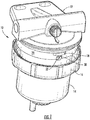
- an embodiment of a disclosed fuel filter assembly 10 comprises a header 12 to which a bowl 14 is secured by a collar 16.
- the collar 16 is configured with inwardly directed spiral ramps (not shown) that engage bosses 18 projecting from the outside surface of a skirt 20 projecting downwardly from the header 12.
- the skirt 20 surrounds an upper inside surface 22 of the header 12, which includes an inward and downward projecting code shoulder 24.
- the code shoulder 24 defines a plurality of code slots 26.
- FIGS 1 and 2 illustrate a notch 30 defined by the skirt 20 which receives a radially projecting stud 32 or embossment extending from a circumferential shoulder 34 of the bowl 14 as best seen in Figure 4 .
- Engagement of the stud 32 with the slot 30 in the skirt 20 defines an installed orientation of the bowl 14 with respect to the header 12.
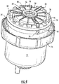
- Figures 2 and 3 illustrate the bowl, received filter element 28 and collar 16 separated from the header 12.
- the bowl 14 includes a castellated upper rim 36 of the bowl 14 and the received filter element 28 upper end cap 38 indexed to the castellated upper rim 36 by a plurality of radially extending supports 40 and a plurality of radially extending code tabs 42.
- the radially extending supports 40 extend radially beyond the outside diameter of the castellated upper rim 36 of the bowl 14.
- the radially extending supports 40 also include a vertical dimension and are molded with vertical support ribs 44 for enhanced structural rigidity.
- the disclosed filter element 28 upper end cap 38 includes three equiangularly arranged radially projecting supports 40, though other support configurations are compatible with the disclosed filter element and filter assembly.
- the upper end cap 38 also includes radially projecting ribs 46 to enhance the structural rigidity of the upper end cap 38.
- a ring-shaped seal 48 At the center of the upper end cap 38 is a ring-shaped seal 48 having a rectangular cross section surrounding a fluid flow aperture 50. Other seal shapes, such as O-rings are compatible with the disclosed filter assembly 10.
- the plurality of radially projecting supports 40 may vary in their lateral (circumferential) dimension, height (measured parallel with a longitudinal axis A of the filter assembly) and/or the extent of their radial projection.
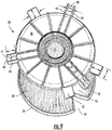
- FIGS. 6 and 7 best show how the notches in the castellated upper rim 36 of the bowl 14 are configured to mate with the supports 40, e.g., the notches are of equal width at both the inside and outside diameters of the upper rim 36 of the bowl 14.
- the upward projections of the castellated rim 36 between the notches are trapezoidal or keystone shaped as a result of the notch configuration.
- the supports 40 center the filter element 28 in the bowl 14 and vertically support the upper end cap 38 with respect to the header 12.
- the radial ribs 46 and vertical component 44 of the supports 40 provide structural rigidity necessary to support the central seal 48 adjacent the upper inside surface 22 of the header 12 to maintain a fluid seal between the filter element 28 and the header 12.
- the element upper end cap 38 also includes one or more radially projecting code tabs 42 employed to code particular elements to particular fuel assemblies.
- the code tabs 42 are in addition to the supports 40. It should be noted that the code tabs 42 are of a simpler structure and a lower vertical profile as the vertical component 44 and rigidity of the supports 40 is unnecessary for the coding function.
- the code tabs 42 are arranged to mate with predetermined notches in the castellated upper rim 36 of the bowl 14 so that an improperly coded filter element will not be received in a bowl 14.
- the code tabs 42 may be used to distinguish elements having different filter properties or capacities or to distinguish filter elements compatible with one manufacturer's products from those compatible with the products of another manufacturer. Together, the supports 40 and code tabs 42 form a compatibility matrix defining a single installed orientation of a filter element 28 with respect to the bowl 14.
- the supports 40 and code tabs 42 extend radially beyond the outside diameter of the castellated upper rim 36 of the bowl 14.
- the bowl 14 Beneath the castellated upper rim 36, the bowl 14 includes a circumferential shoulder 34, the bottom side of which is engaged by an inwardly projecting rim of the collar 16 to support the bowl 14 with respect to the header 12.
- the upper horizontal surface 52 of the shoulder 34 supports an O-ring seal 54 as shown in Figures 5 and 14 .
- the O-ring seal 54 is compressed between the inside surface of the skirt 20 and the outside surface of the castellated upper rim 36 of the bowl 14.
- the circumferential shoulder 34 of the bowl 14 has an outside diameter less than the inside diameter of the downwardly projecting skirt 20 of the header 12.
- the outside diameter of the castellated upper rim 36 of the bowl 14 is less than the inside diameter of the code shoulder 24.
- the castellated upper rim 36 of the bowl 14 sits inside the code shoulder 24 while the circumferential shoulder 34 of the bowl 14 sits inside the skirt 20.
- the radially extending ends of the supports 40 and code tabs 42 are received in the vertical code slots 26 defined by the code shoulder 24.
- the upper end cap 38 of the filter element 28 is keyed to the header 12 by the configuration of radially extending supports 40 and code tabs 42 mating in a corresponding pattern of code slots 26.
- headers 12 are configured with patterns of code slots 26 corresponding to the pattern of supports 40 and code tabs 42 on compatible filter elements 28. Only filter elements 28 with the correct pattern of supports 40 and code tabs 42 are received in the header, while improperly keyed filter elements are rejected.
- the filter element upper end cap 38 is keyed to both the bowl 14 and the header 12, while the bowl 14 is keyed to both the filter element 28 and the header 12.
- the illustrated arrangement employs the pattern of supports 40 and code tabs 42 on the filter element upper end cap 38 as a keyed interface between the bowl 14 and the header 12. An improperly keyed filter element will be rejected, e.g., not fully received in an incompatible header 12, preventing engagement of the ring with the bosses 18, making assembly of an incompatible filter element 28 in the filter assembly 10 impossible.
- Figure 3 illustrates a view of the upper inside surface 22 of the header 12 showing the inwardly projecting code shoulder 24 with code slots 26 corresponding to the radially projecting ends of the supports 40 and code tabs 42.
- the supports 40 and code tabs 42 are configured to traverse the castellated upper rim 36 of the bowl 14 and engage the code slots 26 defined by the code shoulder 24.
- one of the supports 40 is provided with arrows which in the illustrations are aligned with a corresponding arrow on the stud 32 projecting from the circumferential shoulder 34 of the bowl 14.
- the arrows indicate the installed orientation of the filter element 28 with respect to the bowl 14.
- the stud 32 on the circumferential shoulder 34 of the bowl 14 fits in the corresponding notch 30 in the skirt 20 to define the installed orientation of the bowl 14 with respect to the header 12.
- the pattern of supports 40 and code tabs 42 must correspond to the pattern of code slots 26 defined by the code shoulder 24 inside the header 12.
- a circular O-ring seal 50 is supported by the upper surface 52 of the circumferential shoulder 34 of the bowl 14.
- a gland above the circular O-ring is defined by the bottom of the code shoulder 24 and the ends of the radially extending supports 40 and code tabs 42. Missing code tabs 42 or supports 40 will cause voids in the gland above the O-ring seal 50 and may permit vacuum or pressure to deflect the O-ring seal 50 into a code slot 26 and allow leakage.
- the combination of properly positioned supports 40 and code tabs 42, along with the code shoulder 24 define a circumferential upper gland to maintain the position and integrity of the O-ring seal 50.
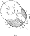
- a filter element 28 has a lower end cap 56 with a V-shaped (wedge-shaped) notch 58.
- the lower end cap 56 and corresponding features of the upper end cap 38 (as shown in Figure 11 ) separate adjacent folds in the cylindrical pleated filter media 60 to define a V-shaped longitudinal channel 62 extending upwardly from the lower end cap 56 to the bottom side of the upper end cap 38.
- the shape of the lower end cap 56 and the channel 62 in the filter media 60 are configured to mate with a corresponding projection 64 from the inside surface of the bowl 14, best seen in Figures 7 , 12 and 13 .
- the projection 64 extends from the bottom of the bowl 14 to a position immediately beneath the castellated upper rim 36 of the bowl, traversing a majority of the height of the inside of the bowl 14.
- the projection 64 is a truncated V-shape complementary to the V-shaped notch 58 and corresponding vertical channel 62 in the filter element 28. As shown in Figure 7 , when the filter element 28 is inserted into the bowl 14, the projection 64 mates with the V-shaped notch 58 in the lower end cap 56 and vertical channel 62 in the filter media 60 to index the lower end cap 56 and filter media 60 to the bowl 14.
- Figure 7 also shows that the notch 58 and vertical channel 62 defined by the filter element lower end cap 56 and media 60, respectively, cooperate with the supports 40 and code tabs 42 of the upper end cap 38 to maintain the upper and lower end caps, 38, 56 of the filter element 28 in predetermined angular orientations with respect to each other when the filter element 28 is received in the bowl 14. Because the upper end cap 38 is indexed to the castellated upper rim 36 of the bowl and the lower end cap 56 is indexed to the projection 64 in the bowl, the bowl 14 serves as a rigid connection between the filter element upper and lower end caps 38, 56 in addition to the connection provided by the filter media 60.
- the support provided by the bowl 14 reduces or eliminates the need for a center support tube connecting the upper and lower end caps 38, 56 of the filter element 28.
- the shape of the notch 58 in the lower end cap 56 and corresponding projection 64 from the inside surface of the bowl 14 are not critical to the disclosure and can take any form where the connection between the projection 64 and the notch 58 control rotational movement of the lower end cap 56 with respect to the bowl 14. Reducing or eliminating the potential for twisting of the lower end cap 56 with respect to the upper end cap 38 enhances stability of the filter media 60 under clogged conditions and helps prevent failure of the filter element 28 when exposed to high differential pressures.
- the upper and lower end caps 38, 56 define a single installed orientation of the filter element 28 with respect to the bowl 14.
- Each of the components of the disclosed filter assembly 10 is keyed to the other independently to define a comprehensive compatibility matrix.
- the filter element upper end cap 38 is coded and keyed to the header 12 by the radial ends of the supports 40 and code tabs 42 mating in corresponding code slots 26 defined by the code shoulder 24.
- the bowl 14 is indexed to the header 12 by the boss 32 projecting from the circumferential shoulder 34 of the bowl 14.
- the filter element 28 is keyed to a single installed orientation with respect to the bowl 14 and serves as a central element of the keyed and coded connection among the components of the filter assembly 10.
- the radially projecting supports and code tabs traverse the castellated upper rim 36 of the bowl to engage the code slots 26 defined by the code shoulder 24 inside the header 12. It will be noted that different numbers and configurations of supports 40 may be used to index the filter element 28 to the bowl 14 and header 12 instead of a combination of supports 40 and code tabs 42.
- the bowl 14, collar 16 and upper and lower end caps 38, 56 are preferably formed from molded plastic.
- the plastic material of the bowl may be transparent to permit inspection of the water level.
- the header is preferably formed of cast aluminum, but may alternatively be molded from plastic.
- the header is cast with a generic code shoulder 24 and code slots 26 are machined to receive compatible filter elements 28.
- the header in an alternative header/collar configuration, includes radially protruding threads which are engaged by complementary threads on the collar (not illustrated). The collar is rotated so that the threads bring the collar toward the header.
- the threads include detents to define the fully installed position of the collar with respect to the header.
- the engagement between the collar 16 and header 12 illustrated in the disclosed embodiments should be considered interchangeable with a threaded engagement.
- the header 12 is physically attached to a vehicle engine or chassis by means of bolts (not shown) passing through the apertures shown in Figures 1 - 3 .
- the header 12 provides an inlet and outlet for the fuel line (not shown).
- a suitable filter element 28 of the type designed to be used with that particular vehicle and with the particular header code shoulder configuration is inserted into the bowl 14 with the supports 40 and code tabs 42 positioned in the notches on the castellated upper rim 36 of the bowl 14.
- the bowl 14 and received filter element 28 are then inserted into the header 12 so that the radially projecting ends of the supports 40 and code tabs 42 are received in the code slots 26 defined by the code shoulder 24 inside the header 12.
- the collar 16 is positioned about the bowl 14 and moved upwardly to engage the bosses 18 on the outside of the skirt 20.
- the collar 14 is rotated, with the bosses 18 riding up the spiral ramps inside the collar 16 and the collar 16 engaging the circumferential shoulder 34 of the bowl to secure the bowl 14 and received filter element 28 to the header 12.
- the upper end cap 38 By providing at least three angularly spaced supports 40, the upper end cap 38 will stay centered and coaxial with the bowl 14.
- the code slots 26 in the header 12 control upward movement of the bowl 14 and received filter element 28 into the header 12. If the supports 40 and code tabs 42 on the filter element upper end cap 38 do not properly align with the code slots 26, or if the supports 40 and code tabs 42 are not properly received in the notches in the castellated upper rim 36 top of the bowl 14 and the filter element 28 will not be received into the header 12 the proper distance. Unless the bowl 14 and received filter element 28 are properly inserted into the header 12, the collar 16 cannot be rotated properly,
- a filter assembly in which an ecological filter unit may be utilized and which provides for an infinite number of configurations to differentiate between filter cartridge assemblies having different flow capabilities, filter unit disposal options and or other characteristics.
Claims (11)
- Élément (28) de filtre, comprenant :un milieu filtrant (60) entourant au moins partiellement un axe central (A) et s'étendant entre des première et deuxième extrémités longitudinales ;un premier embout (38) disposé de manière adjacente à la première extrémité longitudinale du milieu filtrant (60), ledit premier embout (38) délimitant une ouverture (50) d'écoulement de fluide ; etun deuxième embout (56) disposé de manière adjacente à la deuxième extrémité longitudinale du milieu filtrant (60),caractérisé en ce que ledit premier embout (38) comprend au moins une première structure d'indexation (40, 42), la première structure d'indexation (40, 42) étant configurée pour définir une unique orientation d'installation par rapport à un bol (14), et en ce que ledit deuxième embout (56) comprend au moins une deuxième structure d'indexation (58) comprenant une encoche configurée pour s'accoupler avec une saillie complémentaire à partir d'une surface intérieure du bol (14) pour définir une unique orientation d'installation par rapport au bol (14), et en ce que les structures d'indexation (40, 42, 58) desdits premier et deuxième embouts (38, 56) ont une relation angulaire prédéterminée l'une par rapport à l'autre, lesdits premier et deuxième embouts (38, 56) étant chacun configurés pour s'accoupler avec le bol (14) de façon à ce que les deux embouts (38, 56) soient maintenus dans une orientation prédéterminée.
- Élément (28) de filtre selon la revendication 1, dans lequel ledit deuxième embout (56) présente une périphérie extérieure et ladite au moins une deuxième structure d'indexation (58) délimite un vide interrompant la périphérie extérieure dudit deuxième embout (56).
- Élément (28) de filtre selon la revendication 1, dans lequel ledit milieu filtrant (60) présente une configuration généralement cylindrique de bande circonvolutée de matériau filtrant présentant une longueur entre lesdites première et deuxième extrémités longitudinales, ladite au moins une deuxième structure d'indexation (58) délimitant un vide qui interrompt un bord périphérique dudit deuxième embout (56), ladite bande de matériau filtrant suivant la forme dudit deuxième embout (56) pour délimiter un canal (62) parallèle audit axe (A) et aligné avec ladite au moins une deuxième structure d'indexation (58).
- Élément (28) de filtre selon la revendication 1, dans lequel ledit milieu filtrant (60) entoure ledit axe longitudinal (A) pour délimiter un espace intérieur en communication avec ladite ouverture (50) d'écoulement de fluide, ladite au moins une deuxième structure d'indexation (58) délimitant un vide qui interrompt un bord périphérique dudit deuxième embout (56), ledit milieu filtrant (60) prenant la forme dudit deuxième embout (56) pour délimiter un canal (62) s'étendant longitudinalement et aligné avec ladite deuxième structure d'indexation (58).
- Élément (28) de filtre selon la revendication 4, dans lequel ladite deuxième structure d'indexation (58) est en forme de coin et ledit canal (62) s'étendant longitudinalement est aussi en forme de coin et correspond généralement, en forme et position, à ladite deuxième structure d'indexation (58).
- Élément (28) de filtre selon la revendication 1, dans lequel ledit milieu filtrant (60) présente une configuration en coupe généralement constante dans une direction perpendiculaire audit axe longitudinal (A), ladite deuxième structure d'indexation (58) délimitant un vide qui s'étend vers l'intérieur depuis une périphérie extérieure dudit deuxième embout (56) et ladite configuration en coupe du milieu filtrant (60) est généralement la même que la forme dudit deuxième embout (56), ce qui permet de délimiter un canal (62) qui s'étend longitudinalement en faisant saillie vers l'intérieur et est aligné avec ladite deuxième structure d'indexation (58).
- Élément (28) de filtre selon la revendication 1, dans lequel ledit milieu filtrant (60) est une bande plissée en accordéon de matériau filtrant s'étendant entre lesdites première et deuxième extrémités longitudinales, ladite bande plissée comprenant des plis parallèles audit axe longitudinal (A), ladite deuxième structure d'indexation (58) délimitant un vide qui s'étend vers l'intérieur depuis une périphérie extérieure dudit deuxième embout (56), ladite deuxième structure d'indexation (58) séparant des plis adjacents de ladite bande plissée pour délimiter un canal (62) s'étendant longitudinalement et aligné avec ladite deuxième structure d'indexation (58) .
- Élément (28) de filtre selon la revendication 1, dans lequel ledit premier embout (38) présente une périphérie extérieure et ladite au moins une première structure d'indexation comprend une saillie radiale (40, 42) sur la périphérie extérieure dudit premier embout (38).
- Élément (28) de filtre selon la revendication 2, dans lequel ledit milieu filtrant (60) est une bande plissée de matériau filtrant présentant une forme généralement cylindrique, ledit vide (58) est en forme de coin et ledit deuxième embout (56) sépare des plis adjacents dans ladite bande plissée pour délimiter ledit canal (62) s'étendant longitudinalement et présentant une forme de coin sensiblement similaire au vide en forme de coin.
- Élément (28) de filtre selon la revendication 1, dans lequel ladite ouverture (50) d'écoulement de fluide est définie au centre dudit premier embout (38) et ladite au moins une structure d'indexation (40, 42) faisant saillie vers l'extérieur comprend une pluralité de supports (40) espacés angulairement, chaque support étant disposé sur un rayon dudit premier embout (38).
- Élément (28) de filtre selon la revendication 1, dans lequel ladite au moins une structure d'indexation (40, 42) faisant saillie vers l'extérieur comprend une pluralité de supports (40) espacés angulairement ayant une première dimension latérale et une pluralité de languettes (42) de codage espacées angulairement et ayant une deuxième dimension latérale, ladite première dimension latérale étant différente de ladite deuxième dimension latérale.
Applications Claiming Priority (3)
| Application Number | Priority Date | Filing Date | Title |
|---|---|---|---|
| US12/317,409 US20100155321A1 (en) | 2008-12-23 | 2008-12-23 | Filter assembly |
| EP09835869.0A EP2379194B1 (fr) | 2008-12-23 | 2009-12-23 | Ensemble filtre et élément filtrant |
| PCT/US2009/069496 WO2010075564A1 (fr) | 2008-12-23 | 2009-12-23 | Ensemble filtre et élément filtrant |
Related Parent Applications (1)
| Application Number | Title | Priority Date | Filing Date |
|---|---|---|---|
| EP09835869.0A Division EP2379194B1 (fr) | 2008-12-23 | 2009-12-23 | Ensemble filtre et élément filtrant |
Publications (2)
| Publication Number | Publication Date |
|---|---|
| EP3235553A1 EP3235553A1 (fr) | 2017-10-25 |
| EP3235553B1 true EP3235553B1 (fr) | 2020-09-02 |
Family
ID=42264503
Family Applications (2)
| Application Number | Title | Priority Date | Filing Date |
|---|---|---|---|
| EP09835869.0A Active EP2379194B1 (fr) | 2008-12-23 | 2009-12-23 | Ensemble filtre et élément filtrant |
| EP17170047.9A Active EP3235553B1 (fr) | 2008-12-23 | 2009-12-23 | Élément filtrant |
Family Applications Before (1)
| Application Number | Title | Priority Date | Filing Date |
|---|---|---|---|
| EP09835869.0A Active EP2379194B1 (fr) | 2008-12-23 | 2009-12-23 | Ensemble filtre et élément filtrant |
Country Status (6)
| Country | Link |
|---|---|
| US (2) | US20100155321A1 (fr) |
| EP (2) | EP2379194B1 (fr) |
| CN (1) | CN102264446B (fr) |
| BR (1) | BRPI0922471B1 (fr) |
| ES (1) | ES2635788T3 (fr) |
| WO (1) | WO2010075564A1 (fr) |
Families Citing this family (31)
| Publication number | Priority date | Publication date | Assignee | Title |
|---|---|---|---|---|
| US7485881B2 (en) * | 2004-12-29 | 2009-02-03 | Asml Netherlands B.V. | Lithographic apparatus, illumination system, filter system and method for cooling a support of such a filter system |
| CN102933278A (zh) * | 2010-05-18 | 2013-02-13 | 唐纳森公司 | 具有过滤元件的空气滤清器组件和用于安装过滤元件的方法 |
| DE102011077710A1 (de) | 2011-06-17 | 2012-12-20 | Mahle International Gmbh | Ringfilterelement |
| US9086186B2 (en) | 2011-10-14 | 2015-07-21 | Lincoln Industrial Corporation | System having removable lubricant reservoir and lubricant refilling station |
| DE102011088742A1 (de) | 2011-12-15 | 2013-06-20 | Mahle International Gmbh | Filtereinrichtung |
| US9352257B2 (en) | 2012-01-31 | 2016-05-31 | Donaldson Company, Inc. | Interlock device |
| US20150129479A1 (en) * | 2012-04-26 | 2015-05-14 | International Engine Intellectual Property Company Llc | Rotational filter assembly with orientation structure |
| FR2993474B1 (fr) * | 2012-07-19 | 2017-12-22 | Cummins Filtration Sarl | Ensemble de filtrage comportant une cartouche de filtration amovible |
| EP2969117B1 (fr) * | 2013-03-15 | 2021-05-05 | Donaldson Company, Inc. | Cartouches de filtre tubulaires ovoïdes et systèmes de filtre les utilisant |
| BR112015022547B1 (pt) * | 2013-03-15 | 2022-04-19 | Parker-Hannifin Corporation | Cartucho de filtro compósito e método de fabricação do mesmo |
| US10052575B2 (en) * | 2013-04-10 | 2018-08-21 | Clarcor Engine Mobile Solutions, Llc | Filter element |
| US10005012B2 (en) * | 2013-06-06 | 2018-06-26 | Donaldson Company, Inc. | Interlock device |
| US10507421B2 (en) * | 2014-05-07 | 2019-12-17 | Cummins Filtration Ip, Inc. | Filter element with depressed side portion |
| FR3036069B1 (fr) * | 2015-05-13 | 2017-05-26 | Peugeot Citroen Automobiles Sa | Systeme de fixation d'un filtre a carburant. |
| US10245532B2 (en) * | 2016-06-17 | 2019-04-02 | Caterpillar Inc. | Filter center tube with standpipe and flow fins |
| US10343090B2 (en) * | 2016-09-07 | 2019-07-09 | Caterpillar Inc. | Filter element locking mechanism for clean service |
| EP3519075A4 (fr) | 2016-10-03 | 2020-05-27 | Parker-Hannifin Corporation | Élément de filtre avec verrou de torsion et ensemble |
| DE102016012325A1 (de) * | 2016-10-17 | 2018-04-19 | Mann + Hummel Gmbh | Rundfilterelement, insbesondere zur Gasfiltration |
| DE102016012331A1 (de) * | 2016-10-17 | 2018-04-19 | Mann + Hummel Gmbh | Rundfilterelement, insbesondere zur Gasfiltration |
| CN109843409B (zh) | 2016-10-21 | 2021-10-01 | 康明斯过滤Ip公司 | 过滤器组件的碗体 |
| DE102016013844A1 (de) * | 2016-11-22 | 2018-05-24 | Mann + Hummel Gmbh | Rundfilterelement mit längs gestreckter Querschnittsform |
| DE102017003489A1 (de) * | 2017-04-11 | 2018-10-11 | Rt-Filtertechnik Gmbh | Filtervorrichtung |
| EP3401000A1 (fr) * | 2017-05-09 | 2018-11-14 | Donaldson Company, Inc. | Adaptateur et cartouche de filtre à air conçue pour être utilisée avec un tel adaptateur |
| CN110769913B (zh) | 2017-05-31 | 2021-11-16 | 帕克-汉尼芬公司 | 带有扭锁和/或滑动活塞的过滤元件、组件和方法 |
| US11786851B2 (en) | 2017-12-05 | 2023-10-17 | Cummins Filtration Ip, Inc | Self-assisting element removal features for a filtration system |
| US11529572B2 (en) | 2017-12-05 | 2022-12-20 | Cummins Filtration Ip, Inc. | Integral flow structure within a containment cover |
| DE102018001635A1 (de) * | 2018-03-01 | 2019-09-05 | Mann+Hummel Gmbh | Ölabscheiderelement und Ölabscheideranordnung |
| WO2019219635A1 (fr) * | 2018-05-18 | 2019-11-21 | Mann+Hummel Gmbh | Élément filtrant, boîtier conçu pour un système de filtration et système de filtration équipé d'un élément filtrant et d'un boîtier |
| WO2020014141A1 (fr) * | 2018-07-10 | 2020-01-16 | Cummins Filtration Ip, Inc. | Encoche d'alignement pour un capuchon d'extrémité d'un élément filtrant |
| DE102021205304A1 (de) | 2021-05-25 | 2022-12-01 | Mahle International Gmbh | Filter |
| WO2023081101A1 (fr) * | 2021-11-04 | 2023-05-11 | Entegris, Inc. | Ensemble cartouche filtrante |
Family Cites Families (27)
| Publication number | Priority date | Publication date | Assignee | Title |
|---|---|---|---|---|
| DE3903675A1 (de) | 1989-02-08 | 1990-08-09 | Knecht Filterwerke Gmbh | Oelfilter zum reinigen von schmieroel |
| US4976852A (en) * | 1989-06-28 | 1990-12-11 | Stanadyne Automotive Corp. | Fuel filter |
| US5035797A (en) * | 1990-02-14 | 1991-07-30 | Stanadyne Automotive Corp. | Key system for filter assembly |
| US5186829A (en) * | 1991-08-16 | 1993-02-16 | Stanadyne Automotive Corp. | Fuel filter key system |
| US5203994A (en) * | 1991-08-16 | 1993-04-20 | Stanadyne Automotive Corp. | Fuel filter retention system |
| DE69427347T2 (de) * | 1994-08-15 | 2001-10-31 | Ibm | Verfahren und System zur verbesserten Zugriffssteuerung auf Basis der Rollen in verteilten und zentralisierten Rechnersystemen |
| US5753117A (en) * | 1996-06-05 | 1998-05-19 | Fleetguard, Inc. | Replaceable filter element and snap-on filter lid assembly |
| US5837137A (en) * | 1996-08-21 | 1998-11-17 | Stanadyne Automotive Corp. | Base/cartridge location and key system for fuel filter assembly |
| JPH10110657A (ja) * | 1996-08-22 | 1998-04-28 | Stanadyne Automot Corp | 整合カートリッジ支持構造を備えたフィルター・ アセンブリイ |
| US6238552B1 (en) * | 1998-09-04 | 2001-05-29 | Roy T. Shannon | Universal insert for a water purifier |
| US6187188B1 (en) * | 1999-07-19 | 2001-02-13 | Stanadyne Automotive Corp. | Filter cartridge retention system |
| ES2273779T3 (es) * | 2000-02-16 | 2007-05-16 | Stanadyne Corporation | Cartucho y montaje ecologico de filtro de carburante. |
| US6506302B2 (en) * | 2000-02-16 | 2003-01-14 | Stanadyne Corporation | Key system for ecological filter cartridge and element |
| US6949189B2 (en) * | 2000-04-20 | 2005-09-27 | Cuno Incorporated | Keyed filter assembly |
| FR2818917B1 (fr) * | 2000-12-28 | 2003-10-03 | Dan Vasilescu | Filtre pour la depollution particulaire des fluides |
| JP2005523144A (ja) * | 2002-04-19 | 2005-08-04 | キュノ、インコーポレーテッド | 封入フィルター・カートリッジ |
| US20040103626A1 (en) | 2002-08-23 | 2004-06-03 | Warth Scott B. | Filter element, filter assembly, gas turbine system, and methods |
| US6863811B2 (en) * | 2002-10-31 | 2005-03-08 | Stanadyne Corporation | Filter cartridge incorporating a peripheral compatibility matrix |
| US6843911B2 (en) * | 2002-10-31 | 2005-01-18 | Stanadyne Corporation | Base receptacle with fixed retainer for filter cartridge incorporating a peripheral compatibility matrix |
| US7294262B2 (en) * | 2003-08-27 | 2007-11-13 | Sta-Rite Industries, Llc | Modular fluid treatment apparatus |
| EP1781396B1 (fr) | 2004-06-29 | 2011-10-05 | Donaldson Company, Inc. | Systeme de filtre a liquide |
| CN100563779C (zh) * | 2004-06-29 | 2009-12-02 | 唐纳森公司 | 液体过滤器结构和方法 |
| US7387726B2 (en) * | 2005-02-15 | 2008-06-17 | Mann & Hummel Gmbh | Liquid filter system |
| US7487875B2 (en) | 2005-08-30 | 2009-02-10 | General Electric Company | Candle filter assembly and candle filter element |
| US7882961B2 (en) * | 2005-11-01 | 2011-02-08 | Cummins Filtration Ip, Inc. | Replaceable fuel filter element and fuel filter assembly |
| US7897046B2 (en) | 2006-01-25 | 2011-03-01 | Baldwin Filters, Inc. | Fluid filter |
| DE102013000337A1 (de) | 2013-01-11 | 2014-07-17 | Mann + Hummel Gmbh | Filtereinrichtung |
-
2008
- 2008-12-23 US US12/317,409 patent/US20100155321A1/en not_active Abandoned
-
2009
- 2009-12-23 EP EP09835869.0A patent/EP2379194B1/fr active Active
- 2009-12-23 ES ES09835869.0T patent/ES2635788T3/es active Active
- 2009-12-23 US US13/141,347 patent/US10702807B2/en active Active
- 2009-12-23 BR BRPI0922471-8A patent/BRPI0922471B1/pt active IP Right Grant
- 2009-12-23 WO PCT/US2009/069496 patent/WO2010075564A1/fr active Application Filing
- 2009-12-23 EP EP17170047.9A patent/EP3235553B1/fr active Active
- 2009-12-23 CN CN200980152130.4A patent/CN102264446B/zh active Active
Non-Patent Citations (1)
| Title |
|---|
| None * |
Also Published As
| Publication number | Publication date |
|---|---|
| US20110272340A1 (en) | 2011-11-10 |
| BRPI0922471A2 (pt) | 2017-06-06 |
| US10702807B2 (en) | 2020-07-07 |
| WO2010075564A1 (fr) | 2010-07-01 |
| CN102264446A (zh) | 2011-11-30 |
| EP2379194B1 (fr) | 2017-05-10 |
| EP2379194A4 (fr) | 2012-07-18 |
| BRPI0922471A8 (pt) | 2017-10-03 |
| CN102264446B (zh) | 2014-06-04 |
| EP2379194A1 (fr) | 2011-10-26 |
| US20100155321A1 (en) | 2010-06-24 |
| ES2635788T3 (es) | 2017-10-04 |
| EP3235553A1 (fr) | 2017-10-25 |
| BRPI0922471B1 (pt) | 2019-11-12 |
Similar Documents
| Publication | Publication Date | Title |
|---|---|---|
| EP3235553B1 (fr) | Élément filtrant | |
| US6506302B2 (en) | Key system for ecological filter cartridge and element | |
| EP2340883B1 (fr) | Ensemble filtre a liquides | |
| EP3705165B1 (fr) | Ensemble filtre de fluide comportant une cartouche filtrante | |
| EP0532161B1 (fr) | Système de clef pour filtre de carburant | |
| CN102438717B (zh) | 具有卡扣安装的过滤器的多级滤芯 | |
| US20200122067A1 (en) | Filter Element and Filter System for a Liquid Medium, in Particular Diesel Fuel | |
| US6740234B1 (en) | Key track system | |
| EP0826406A1 (fr) | Fixation support cartouche et système de calage pour un assemblage de filtre de carburant | |
| US20090057219A1 (en) | Replaceable filter elements including unique interfaces and filtration systems including same | |
| EP1565244B1 (fr) | Cartouche de filtre incorporant une matrice a compatibilite peripherique | |
| EP1558357B1 (fr) | Systeme de retenue par interference excentrique pour cartouche filtrante | |
| US6911143B2 (en) | Base receptacle for filter cartridge incorporating a peripheral compatibility matrix | |
| US6814243B2 (en) | Replaceable filter with locking mechanism | |
| US7314555B2 (en) | Filter cartridge for a filter assembly | |
| WO2017050370A1 (fr) | Insert de filtre et agencement de filtre | |
| WO2006094065A2 (fr) | Caracteristiques ameliorees pour dispositifs de filtres a liquide, composants et ensembles de filtres resultants, et procedes associes | |
| CN111867702A (zh) | 具有非圆形横截面的过滤器元件和壳体 | |
| WO2010074676A1 (fr) | Ensemble filtre | |
| CN112154023B (zh) | 包括可移除式出口导管的过滤器组件 |
Legal Events
| Date | Code | Title | Description |
|---|---|---|---|
| PUAI | Public reference made under article 153(3) epc to a published international application that has entered the european phase |
Free format text: ORIGINAL CODE: 0009012 |
|
| STAA | Information on the status of an ep patent application or granted ep patent |
Free format text: STATUS: THE APPLICATION HAS BEEN PUBLISHED |
|
| AC | Divisional application: reference to earlier application |
Ref document number: 2379194 Country of ref document: EP Kind code of ref document: P |
|
| AK | Designated contracting states |
Kind code of ref document: A1 Designated state(s): AT BE BG CH CY CZ DE DK EE ES FI FR GB GR HR HU IE IS IT LI LT LU LV MC MK MT NL NO PL PT RO SE SI SK SM TR |
|
| RIN1 | Information on inventor provided before grant (corrected) |
Inventor name: SASUR, TIMOTHY M Inventor name: SAZAMA, JEREMIAH |
|
| STAA | Information on the status of an ep patent application or granted ep patent |
Free format text: STATUS: REQUEST FOR EXAMINATION WAS MADE |
|
| 17P | Request for examination filed |
Effective date: 20180425 |
|
| RBV | Designated contracting states (corrected) |
Designated state(s): AT BE BG CH CY CZ DE DK EE ES FI FR GB GR HR HU IE IS IT LI LT LU LV MC MK MT NL NO PL PT RO SE SI SK SM TR |
|
| STAA | Information on the status of an ep patent application or granted ep patent |
Free format text: STATUS: EXAMINATION IS IN PROGRESS |
|
| 17Q | First examination report despatched |
Effective date: 20190320 |
|
| GRAP | Despatch of communication of intention to grant a patent |
Free format text: ORIGINAL CODE: EPIDOSNIGR1 |
|
| STAA | Information on the status of an ep patent application or granted ep patent |
Free format text: STATUS: GRANT OF PATENT IS INTENDED |
|
| INTG | Intention to grant announced |
Effective date: 20200325 |
|
| GRAS | Grant fee paid |
Free format text: ORIGINAL CODE: EPIDOSNIGR3 |
|
| GRAA | (expected) grant |
Free format text: ORIGINAL CODE: 0009210 |
|
| STAA | Information on the status of an ep patent application or granted ep patent |
Free format text: STATUS: THE PATENT HAS BEEN GRANTED |
|
| AC | Divisional application: reference to earlier application |
Ref document number: 2379194 Country of ref document: EP Kind code of ref document: P |
|
| AK | Designated contracting states |
Kind code of ref document: B1 Designated state(s): AT BE BG CH CY CZ DE DK EE ES FI FR GB GR HR HU IE IS IT LI LT LU LV MC MK MT NL NO PL PT RO SE SI SK SM TR |
|
| REG | Reference to a national code |
Ref country code: GB Ref legal event code: FG4D |
|
| REG | Reference to a national code |
Ref country code: AT Ref legal event code: REF Ref document number: 1308150 Country of ref document: AT Kind code of ref document: T Effective date: 20200915 Ref country code: CH Ref legal event code: EP |
|
| REG | Reference to a national code |
Ref country code: DE Ref legal event code: R096 Ref document number: 602009062731 Country of ref document: DE |
|
| REG | Reference to a national code |
Ref country code: IE Ref legal event code: FG4D |
|
| REG | Reference to a national code |
Ref country code: LT Ref legal event code: MG4D |
|
| PG25 | Lapsed in a contracting state [announced via postgrant information from national office to epo] |
Ref country code: BG Free format text: LAPSE BECAUSE OF FAILURE TO SUBMIT A TRANSLATION OF THE DESCRIPTION OR TO PAY THE FEE WITHIN THE PRESCRIBED TIME-LIMIT Effective date: 20201202 Ref country code: LT Free format text: LAPSE BECAUSE OF FAILURE TO SUBMIT A TRANSLATION OF THE DESCRIPTION OR TO PAY THE FEE WITHIN THE PRESCRIBED TIME-LIMIT Effective date: 20200902 Ref country code: FI Free format text: LAPSE BECAUSE OF FAILURE TO SUBMIT A TRANSLATION OF THE DESCRIPTION OR TO PAY THE FEE WITHIN THE PRESCRIBED TIME-LIMIT Effective date: 20200902 Ref country code: SE Free format text: LAPSE BECAUSE OF FAILURE TO SUBMIT A TRANSLATION OF THE DESCRIPTION OR TO PAY THE FEE WITHIN THE PRESCRIBED TIME-LIMIT Effective date: 20200902 Ref country code: HR Free format text: LAPSE BECAUSE OF FAILURE TO SUBMIT A TRANSLATION OF THE DESCRIPTION OR TO PAY THE FEE WITHIN THE PRESCRIBED TIME-LIMIT Effective date: 20200902 Ref country code: GR Free format text: LAPSE BECAUSE OF FAILURE TO SUBMIT A TRANSLATION OF THE DESCRIPTION OR TO PAY THE FEE WITHIN THE PRESCRIBED TIME-LIMIT Effective date: 20201203 Ref country code: NO Free format text: LAPSE BECAUSE OF FAILURE TO SUBMIT A TRANSLATION OF THE DESCRIPTION OR TO PAY THE FEE WITHIN THE PRESCRIBED TIME-LIMIT Effective date: 20201202 |
|
| REG | Reference to a national code |
Ref country code: NL Ref legal event code: MP Effective date: 20200902 |
|
| REG | Reference to a national code |
Ref country code: AT Ref legal event code: MK05 Ref document number: 1308150 Country of ref document: AT Kind code of ref document: T Effective date: 20200902 |
|
| PG25 | Lapsed in a contracting state [announced via postgrant information from national office to epo] |
Ref country code: PL Free format text: LAPSE BECAUSE OF FAILURE TO SUBMIT A TRANSLATION OF THE DESCRIPTION OR TO PAY THE FEE WITHIN THE PRESCRIBED TIME-LIMIT Effective date: 20200902 Ref country code: LV Free format text: LAPSE BECAUSE OF FAILURE TO SUBMIT A TRANSLATION OF THE DESCRIPTION OR TO PAY THE FEE WITHIN THE PRESCRIBED TIME-LIMIT Effective date: 20200902 |
|
| PG25 | Lapsed in a contracting state [announced via postgrant information from national office to epo] |
Ref country code: PT Free format text: LAPSE BECAUSE OF FAILURE TO SUBMIT A TRANSLATION OF THE DESCRIPTION OR TO PAY THE FEE WITHIN THE PRESCRIBED TIME-LIMIT Effective date: 20210104 Ref country code: RO Free format text: LAPSE BECAUSE OF FAILURE TO SUBMIT A TRANSLATION OF THE DESCRIPTION OR TO PAY THE FEE WITHIN THE PRESCRIBED TIME-LIMIT Effective date: 20200902 Ref country code: CZ Free format text: LAPSE BECAUSE OF FAILURE TO SUBMIT A TRANSLATION OF THE DESCRIPTION OR TO PAY THE FEE WITHIN THE PRESCRIBED TIME-LIMIT Effective date: 20200902 Ref country code: SM Free format text: LAPSE BECAUSE OF FAILURE TO SUBMIT A TRANSLATION OF THE DESCRIPTION OR TO PAY THE FEE WITHIN THE PRESCRIBED TIME-LIMIT Effective date: 20200902 Ref country code: EE Free format text: LAPSE BECAUSE OF FAILURE TO SUBMIT A TRANSLATION OF THE DESCRIPTION OR TO PAY THE FEE WITHIN THE PRESCRIBED TIME-LIMIT Effective date: 20200902 |
|
| PG25 | Lapsed in a contracting state [announced via postgrant information from national office to epo] |
Ref country code: IS Free format text: LAPSE BECAUSE OF FAILURE TO SUBMIT A TRANSLATION OF THE DESCRIPTION OR TO PAY THE FEE WITHIN THE PRESCRIBED TIME-LIMIT Effective date: 20210102 Ref country code: AT Free format text: LAPSE BECAUSE OF FAILURE TO SUBMIT A TRANSLATION OF THE DESCRIPTION OR TO PAY THE FEE WITHIN THE PRESCRIBED TIME-LIMIT Effective date: 20200902 Ref country code: ES Free format text: LAPSE BECAUSE OF FAILURE TO SUBMIT A TRANSLATION OF THE DESCRIPTION OR TO PAY THE FEE WITHIN THE PRESCRIBED TIME-LIMIT Effective date: 20200902 |
|
| REG | Reference to a national code |
Ref country code: DE Ref legal event code: R097 Ref document number: 602009062731 Country of ref document: DE |
|
| PG25 | Lapsed in a contracting state [announced via postgrant information from national office to epo] |
Ref country code: SK Free format text: LAPSE BECAUSE OF FAILURE TO SUBMIT A TRANSLATION OF THE DESCRIPTION OR TO PAY THE FEE WITHIN THE PRESCRIBED TIME-LIMIT Effective date: 20200902 |
|
| PLBE | No opposition filed within time limit |
Free format text: ORIGINAL CODE: 0009261 |
|
| STAA | Information on the status of an ep patent application or granted ep patent |
Free format text: STATUS: NO OPPOSITION FILED WITHIN TIME LIMIT |
|
| REG | Reference to a national code |
Ref country code: CH Ref legal event code: PL |
|
| 26N | No opposition filed |
Effective date: 20210603 |
|
| PG25 | Lapsed in a contracting state [announced via postgrant information from national office to epo] |
Ref country code: DK Free format text: LAPSE BECAUSE OF FAILURE TO SUBMIT A TRANSLATION OF THE DESCRIPTION OR TO PAY THE FEE WITHIN THE PRESCRIBED TIME-LIMIT Effective date: 20200902 Ref country code: SI Free format text: LAPSE BECAUSE OF FAILURE TO SUBMIT A TRANSLATION OF THE DESCRIPTION OR TO PAY THE FEE WITHIN THE PRESCRIBED TIME-LIMIT Effective date: 20200902 Ref country code: MC Free format text: LAPSE BECAUSE OF FAILURE TO SUBMIT A TRANSLATION OF THE DESCRIPTION OR TO PAY THE FEE WITHIN THE PRESCRIBED TIME-LIMIT Effective date: 20200902 |
|
| REG | Reference to a national code |
Ref country code: BE Ref legal event code: MM Effective date: 20201231 |
|
| PG25 | Lapsed in a contracting state [announced via postgrant information from national office to epo] |
Ref country code: IE Free format text: LAPSE BECAUSE OF NON-PAYMENT OF DUE FEES Effective date: 20201223 Ref country code: LU Free format text: LAPSE BECAUSE OF NON-PAYMENT OF DUE FEES Effective date: 20201223 Ref country code: IT Free format text: LAPSE BECAUSE OF FAILURE TO SUBMIT A TRANSLATION OF THE DESCRIPTION OR TO PAY THE FEE WITHIN THE PRESCRIBED TIME-LIMIT Effective date: 20200902 |
|
| PG25 | Lapsed in a contracting state [announced via postgrant information from national office to epo] |
Ref country code: CH Free format text: LAPSE BECAUSE OF NON-PAYMENT OF DUE FEES Effective date: 20201231 Ref country code: LI Free format text: LAPSE BECAUSE OF NON-PAYMENT OF DUE FEES Effective date: 20201231 |
|
| PG25 | Lapsed in a contracting state [announced via postgrant information from national office to epo] |
Ref country code: TR Free format text: LAPSE BECAUSE OF FAILURE TO SUBMIT A TRANSLATION OF THE DESCRIPTION OR TO PAY THE FEE WITHIN THE PRESCRIBED TIME-LIMIT Effective date: 20200902 Ref country code: MT Free format text: LAPSE BECAUSE OF FAILURE TO SUBMIT A TRANSLATION OF THE DESCRIPTION OR TO PAY THE FEE WITHIN THE PRESCRIBED TIME-LIMIT Effective date: 20200902 Ref country code: CY Free format text: LAPSE BECAUSE OF FAILURE TO SUBMIT A TRANSLATION OF THE DESCRIPTION OR TO PAY THE FEE WITHIN THE PRESCRIBED TIME-LIMIT Effective date: 20200902 |
|
| PG25 | Lapsed in a contracting state [announced via postgrant information from national office to epo] |
Ref country code: MK Free format text: LAPSE BECAUSE OF FAILURE TO SUBMIT A TRANSLATION OF THE DESCRIPTION OR TO PAY THE FEE WITHIN THE PRESCRIBED TIME-LIMIT Effective date: 20200902 |
|
| PG25 | Lapsed in a contracting state [announced via postgrant information from national office to epo] |
Ref country code: BE Free format text: LAPSE BECAUSE OF NON-PAYMENT OF DUE FEES Effective date: 20201231 |
|
| PGFP | Annual fee paid to national office [announced via postgrant information from national office to epo] |
Ref country code: DE Payment date: 20221228 Year of fee payment: 14 |
|
| P01 | Opt-out of the competence of the unified patent court (upc) registered |
Effective date: 20230524 |
|
| PG25 | Lapsed in a contracting state [announced via postgrant information from national office to epo] |
Ref country code: NL Free format text: LAPSE BECAUSE OF NON-PAYMENT OF DUE FEES Effective date: 20200923 |
|
| PGFP | Annual fee paid to national office [announced via postgrant information from national office to epo] |
Ref country code: GB Payment date: 20231227 Year of fee payment: 15 |
|
| PGFP | Annual fee paid to national office [announced via postgrant information from national office to epo] |
Ref country code: FR Payment date: 20231227 Year of fee payment: 15 |