EP3235286B1 - Verfahren zur analyse einer drahtlosen verbindung eines wifi-knotens, entsprechende schaltung zur durchführung des verfahrens und anwendung - Google Patents
Verfahren zur analyse einer drahtlosen verbindung eines wifi-knotens, entsprechende schaltung zur durchführung des verfahrens und anwendung Download PDFInfo
- Publication number
- EP3235286B1 EP3235286B1 EP15810732.6A EP15810732A EP3235286B1 EP 3235286 B1 EP3235286 B1 EP 3235286B1 EP 15810732 A EP15810732 A EP 15810732A EP 3235286 B1 EP3235286 B1 EP 3235286B1
- Authority
- EP
- European Patent Office
- Prior art keywords
- parameters
- rate
- test
- data
- rssi
- Prior art date
- Legal status (The legal status is an assumption and is not a legal conclusion. Google has not performed a legal analysis and makes no representation as to the accuracy of the status listed.)
- Active
Links
- 238000000034 method Methods 0.000 title claims description 35
- 238000012360 testing method Methods 0.000 claims description 89
- 230000005540 biological transmission Effects 0.000 claims description 28
- 238000012544 monitoring process Methods 0.000 claims description 17
- 230000007246 mechanism Effects 0.000 claims description 10
- 230000000694 effects Effects 0.000 claims description 7
- 238000001914 filtration Methods 0.000 claims description 6
- 238000012937 correction Methods 0.000 claims description 4
- 238000004891 communication Methods 0.000 description 13
- 230000006870 function Effects 0.000 description 9
- 238000005259 measurement Methods 0.000 description 9
- 230000000704 physical effect Effects 0.000 description 7
- 230000006978 adaptation Effects 0.000 description 5
- 230000008859 change Effects 0.000 description 5
- 230000009471 action Effects 0.000 description 4
- 230000002829 reductive effect Effects 0.000 description 4
- 238000012935 Averaging Methods 0.000 description 3
- 238000005516 engineering process Methods 0.000 description 3
- 230000000903 blocking effect Effects 0.000 description 2
- 238000006243 chemical reaction Methods 0.000 description 2
- 230000001419 dependent effect Effects 0.000 description 2
- 238000013213 extrapolation Methods 0.000 description 2
- 230000036314 physical performance Effects 0.000 description 2
- 238000001303 quality assessment method Methods 0.000 description 2
- 230000009467 reduction Effects 0.000 description 2
- WNEODWDFDXWOLU-QHCPKHFHSA-N 3-[3-(hydroxymethyl)-4-[1-methyl-5-[[5-[(2s)-2-methyl-4-(oxetan-3-yl)piperazin-1-yl]pyridin-2-yl]amino]-6-oxopyridin-3-yl]pyridin-2-yl]-7,7-dimethyl-1,2,6,8-tetrahydrocyclopenta[3,4]pyrrolo[3,5-b]pyrazin-4-one Chemical compound C([C@@H](N(CC1)C=2C=NC(NC=3C(N(C)C=C(C=3)C=3C(=C(N4C(C5=CC=6CC(C)(C)CC=6N5CC4)=O)N=CC=3)CO)=O)=CC=2)C)N1C1COC1 WNEODWDFDXWOLU-QHCPKHFHSA-N 0.000 description 1
- RYGMFSIKBFXOCR-UHFFFAOYSA-N Copper Chemical compound [Cu] RYGMFSIKBFXOCR-UHFFFAOYSA-N 0.000 description 1
- 241000590419 Polygonia interrogationis Species 0.000 description 1
- 230000002776 aggregation Effects 0.000 description 1
- 238000004220 aggregation Methods 0.000 description 1
- 238000013459 approach Methods 0.000 description 1
- 239000000872 buffer Substances 0.000 description 1
- 230000015556 catabolic process Effects 0.000 description 1
- 229910052802 copper Inorganic materials 0.000 description 1
- 239000010949 copper Substances 0.000 description 1
- 230000003247 decreasing effect Effects 0.000 description 1
- 238000006731 degradation reaction Methods 0.000 description 1
- 239000006185 dispersion Substances 0.000 description 1
- 230000003116 impacting effect Effects 0.000 description 1
- 230000006872 improvement Effects 0.000 description 1
- 238000009434 installation Methods 0.000 description 1
- 230000003993 interaction Effects 0.000 description 1
- 230000000670 limiting effect Effects 0.000 description 1
- 238000012986 modification Methods 0.000 description 1
- 230000004048 modification Effects 0.000 description 1
- 230000003287 optical effect Effects 0.000 description 1
- 230000000717 retained effect Effects 0.000 description 1
- 230000003068 static effect Effects 0.000 description 1
- 230000001360 synchronised effect Effects 0.000 description 1
- 238000012549 training Methods 0.000 description 1
- 238000012546 transfer Methods 0.000 description 1
Images


Classifications
-
- H—ELECTRICITY
- H04—ELECTRIC COMMUNICATION TECHNIQUE
- H04W—WIRELESS COMMUNICATION NETWORKS
- H04W24/00—Supervisory, monitoring or testing arrangements
- H04W24/08—Testing, supervising or monitoring using real traffic
-
- H—ELECTRICITY
- H04—ELECTRIC COMMUNICATION TECHNIQUE
- H04L—TRANSMISSION OF DIGITAL INFORMATION, e.g. TELEGRAPHIC COMMUNICATION
- H04L43/00—Arrangements for monitoring or testing data switching networks
- H04L43/04—Processing captured monitoring data, e.g. for logfile generation
- H04L43/045—Processing captured monitoring data, e.g. for logfile generation for graphical visualisation of monitoring data
-
- H—ELECTRICITY
- H04—ELECTRIC COMMUNICATION TECHNIQUE
- H04L—TRANSMISSION OF DIGITAL INFORMATION, e.g. TELEGRAPHIC COMMUNICATION
- H04L43/00—Arrangements for monitoring or testing data switching networks
- H04L43/08—Monitoring or testing based on specific metrics, e.g. QoS, energy consumption or environmental parameters
- H04L43/0876—Network utilisation, e.g. volume of load or congestion level
- H04L43/0888—Throughput
-
- H—ELECTRICITY
- H04—ELECTRIC COMMUNICATION TECHNIQUE
- H04L—TRANSMISSION OF DIGITAL INFORMATION, e.g. TELEGRAPHIC COMMUNICATION
- H04L43/00—Arrangements for monitoring or testing data switching networks
- H04L43/16—Threshold monitoring
-
- H—ELECTRICITY
- H04—ELECTRIC COMMUNICATION TECHNIQUE
- H04L—TRANSMISSION OF DIGITAL INFORMATION, e.g. TELEGRAPHIC COMMUNICATION
- H04L43/00—Arrangements for monitoring or testing data switching networks
- H04L43/50—Testing arrangements
-
- H—ELECTRICITY
- H04—ELECTRIC COMMUNICATION TECHNIQUE
- H04W—WIRELESS COMMUNICATION NETWORKS
- H04W24/00—Supervisory, monitoring or testing arrangements
- H04W24/06—Testing, supervising or monitoring using simulated traffic
-
- H—ELECTRICITY
- H04—ELECTRIC COMMUNICATION TECHNIQUE
- H04W—WIRELESS COMMUNICATION NETWORKS
- H04W28/00—Network traffic management; Network resource management
- H04W28/16—Central resource management; Negotiation of resources or communication parameters, e.g. negotiating bandwidth or QoS [Quality of Service]
- H04W28/18—Negotiating wireless communication parameters
- H04W28/22—Negotiating communication rate
Definitions
- the present disclosure relates to the field of wireless nodes and respective devices communicating with each other via a wireless communication.
- Access gateways are widely used to connect devices in a home to the Internet or any other wide area network (WAN). Access gateways use in particular digital subscriber line (DSL) technology that enables a high data rate transmission over copper lines or optical lines.
- DSL digital subscriber line
- Residential gateways, as well as other devices such as routers, switches, telephones and set-top boxes, are understood in this context as customer premises equipment (CPE) devices.
- CPE customer premises equipment
- Wi-Fi wireless local area network
- STA station
- AP access point
- WLAN wireless local area network
- IEEE 802.11 networks apply a medium access method in which collisions are avoided by sensing that the medium is used (denoted as CSMA-CA).
- the medium access method is also commonly known as "listen before talk”, describing the essence of the method and is referred to as “Clear Channel Assessment” (CCA).
- Clear channel assessment determines whether a wireless communication channel is "occupied”, e.g., "busy” with another wireless communication and/or has an amount of interference that makes the wireless communication channel unsuitable for communication. In this way, it is determined whether the wireless communication channel is available or not available for communication, e.g. occupied or not occupied.
- the physical layer rate also referred to in the following as "TrainedPhyRate” or modulation rate, relates to the transfer rate on the physical layer of the wireless connection.
- the IEEE 802.11 MAC protocols use rate adaptation mechanisms for evaluating the properties of the wireless channel and select an appropriate physical layer rate.
- the interference is not detected by the CCA of the transmitter, but is decreasing the SINR (Signal to Noise and Interference Ratio) of the Wi-Fi packets as seen by the receiver.
- SINR Signal to Noise and Interference Ratio
- Wi-Fi nodes will react to packet loss by lowering the physical layer rate used towards a more robust - but slower - physical layer rate in an attempt to increase the chance of successfully transmitting packets.
- the Wi-Fi connection can suffer from poor performance and even connection loss.
- Some of these circumstances are obvious and easy to explain to an end user. For example, if the distance between the station and the AP is too large, then signal levels are low and performance will degrade.
- Other circumstances are "invisible" and not understood by the end user, e.g. a hidden node.
- a hidden node is invisible to some of the nodes of a network, leading to a practical failure of the CSMA-CA method, which can cause packet collision/corruption over air. In many cases, the end user is not able to diagnose the problem source and correct the issue.
- Patent application WO2014/011191A1 describes a method and system for improving performance estimation of a communication device by using operational data together with active probing data to train a performance estimation algorithm.
- operational data is monitored regularly and used to accurately update the performance estimation without interrupting customer traffic over the network.
- Patent application US 2013/301443A1 describes methods for implementing a differential signal to noise ratio (DSNR) based rate adaptation for wireless networks.
- the methods probabilistically adapt the rate of data transmission based on an assessment of the causes of data loss.
- the methods include determining a DSNR for data transmission during a predetermined window of time and adapting the transmission rate in a probabilistic manner responsive to the differential SNR and a differential SNR threshold for the data transmission.
- the ideal way to analyze Wi-Fi issues is by looking into the master node of the wireless LAN, namely the AP.
- the AP as defined in IEEE 802.11, controls the network, hence all data and network control is visible by the AP.
- the AP today can deliver statistics regarding packet transmission and signal levels. But the real issue why a link is dropped or why throughput is low, remains hidden to the internals of the AP.
- Today, at best an AP can deliver statistics but no view on what is actually happening in the wireless network.
- Wi-Fi performance can be degraded because of the following categories. For each category, a different action has to be taken to improve things:
- the problem to solve is to have an application that can correctly analyze Wi-Fi performance issues and indicate the correct category causing the issue, so that the end user can be guided to a suitable corrective action.
- the invention provides a method according to claim 1 for analyzing a wireless link of a wireless node of a customer premises equipment, CPE, device, the method comprising performing a first test, during which a data transmission is forced through the wireless link, to obtain a first set of parameters, and performing a second test, which is a monitoring mode during which a data transmission of the wireless link is monitored, to obtain a second set of parameters, characterized in that the first set of parameters comprise at least a measured data rate with a Received Signal Strength Indicator, RSSI, value, the second set of parameters comprise at least clear channel assessment statistics and if the measured data rate with the RSSI value is within the boundary of reference data, said reference data comprising two sets of data rates with RSSI values measured at two different times in an interference free environment and for two different conditions of path loss, an observed decrease in the measured data rate is assigned to Physics effects or to a Far End Interference, wherein the observed decrease in the measured data rate is assigned to Far End Interference if the channel assessment statistics of the second parameters
- the invention provides a device according to claim 8, the device comprising a processor, a memory and a wireless node, said processor being configured to perform: a first test, during which a data transmission is forced through the wireless link, to obtain a first set of parameters, and a second test, which is a monitoring mode during which a data transmission of the wireless link is monitored, to obtain a second set of parameters characterized in that the first set of parameters comprise at least a measured data rate with a Received Signal Strength Indicator, RSSI, value, the second set of parameters comprise at least clear channel assessment statistics and if the measured data rate with the RSSI value is within the boundary of reference data, said reference data comprising two sets of data rates with RSSI values measured at two different times in an interference free environment and for two different conditions of path loss, an observed decrease in the measured data rate is assigned to Physics effects or to a Far End Interference, wherein the observed decrease in the measured data rate is assigned to Far End Interference if the channel assessment statistics of the second parameters indicate the presence of interferences.
- the invention provides a non-transitory program storage medium according to claim 14, the non-transitory program storage medium being readable by a computer and comprising executable program code for performing a method in accordance with any one claims 1 to 7 when executed by the computer.
- the invention provides an application according to claim 15, the application comprising executable program code for performing a method in accordance with any one of claims 1 to 7 when executed by a computer.
- the elements shown in the figures may be implemented in various forms of hardware, software or combinations thereof. Preferably, these elements are implemented in a combination of hardware and software on one or more appropriately programmed general-purpose devices, which may include a processor, memory and input/output interfaces.
- general-purpose devices which may include a processor, memory and input/output interfaces.
- the phrase "coupled" is defined to mean directly connected to or indirectly connected with through one or more intermediate components. Such intermediate components may include both hardware and software based components.
- processor or “controller” should not be construed to refer exclusively to hardware capable of executing software, and may implicitly include, without limitation, digital signal processor ("DSP") hardware, read only memory (“ROM”) for storing software, random access memory (“RAM”), and nonvolatile storage.
- DSP digital signal processor
- ROM read only memory
- RAM random access memory
- any switches shown in the figures are conceptual only. Their function may be carried out through the operation of program logic, through dedicated logic, through the interaction of program control and dedicated logic, or even manually, the particular technique being selectable by the implementer as more specifically understood from the context.
- any element expressed as a means for performing a specified function is intended to encompass any way of performing that function including, for example, a) a combination of circuit elements that performs that function or b) software in any form, including, therefore, firmware, microcode or the like, combined with appropriate circuitry for executing that software to perform the function.
- a CPE device includes, but is not limited to, in an embodiment a processor, e.g. a microprocessor, a memory, in which an operating system is stored for the operation of the CPE device, a wireless node for a wireless operation, and a broadband connection, e.g. an xDSL connection.
- the wireless node includes, but is not limited to, a complex software driver, a physical layer with data buffers, and an antenna.
- a CPE device of this kind is for example an access gateway, e.g. a residential gateway, which has a central position within a wireless local area network (WLAN).
- WLAN wireless local area network
- the wireless node is controlled by the software driver, which executes a number of background tasks during operation of the wireless node, e.g. dynamic rate adaptation, packet aggregation, channel quality monitoring, and the like.
- the software driver On top of signal manipulations, the software driver also embeds an IEEE 802.11 protocol stack with an associated IEEE defined management and control messaging. The software driver will hence inject a number of management and control packets into the data stream, making it difficult to analyze a link by transparently looking at the data frame exchange only.
- FIG. 1 An arrangement illustrating a wireless communication is schematically depicted in figure 1 :
- An access point 1 communicates with a station 2 via a wireless link 3.
- the access point 1 includes a circuit comprising a microprocessor 10, a memory 11, a wireless node 12 for the wireless communication, and a test application 13.
- the station 2 includes a second circuit comprising a microprocessor 20, a memory 21, a wireless node 22 for the wireless communication, and a test application 23.
- the wireless node 12 includes a physical layer 14 and a link layer 15, and the wireless node 22 includes a physical layer 24 and a link layer 25.
- the access point 1 is for example a residential gateway establishing with the station 2 a home network of an end-user.
- the test application 13 comprises instructions for the microprocessor 10 and the test application 23 comprises instructions for the microprocessor 20, which instructions are included for diagnosing the wireless link 3 and which gather an information set about the wireless link 3.
- the information set includes in particular achievable data rate, physical layer data rate, multiple spatial streams, channel bandwidth, medium availability and a Received Signal Strength Indicator (RSSI). These data can be gathered in a passive mode, in which a data transmission is monitored between the access point 1 and the station 2 or vice versa, or in an active mode, in which a data transmission is forced between the access point 1 and the station 2.
- RSSI Received Signal Strength Indicator
- the test application 13 in the access point 1 is trying to push as many data as possible through the wireless link 3 to the station 2 during a specific test period.
- the test application 13 is situated purely at a Media Access Control (MAC) layer (layer 2).
- MAC Media Access Control
- the test application 13 in the gateway can autonomously measure the layer 2 data rate during the active test. This takes care of testing the Wi-Fi performance, which is only one step.
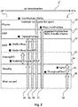
- Figure 2 illustrates the possibilities which have to be considered when diagnosing the Wi-Fi performance of the access point 1 and the station 2.
- An unidirectional link 3' from the access point 1 to the station 2 is examined in this embodiment.
- a theoretical maximum data rate 30 for this link is given by the capabilities of the access point 1 and the station 2, called here MaxNegotiatedPhyRate or MaxPhyRate, which is for example 130 MB/s, in case of IEEE 802.11n with 20 MHz channel bandwidth and two spatial streams (and no short guard interval) is selected for the transmission between the access point 1 and the station 2.
- MaxNegotiatedPhyRate MaxPhyRate
- MaxPhyRate 30 The maximum available physical layer rate for the transmission between the access point 1 and the station 2, MaxPhyRate 30, as negotiated, can be obtained by including the maximum available data rates for the IEEE standards 802.11b, 802.11g and 802.11n as a function of the number of spatial streams (MIMO Configuration), channel bandwidth (20 or 40 MHz), and SGI (Short Guard Interval) enabled or not enabled.
- MIMO Configuration the number of spatial streams
- channel bandwidth (20 or 40 MHz
- SGI Short Guard Interval
- the received signal strength RSSI at the station side is reduced for example due to the distance between the access point 1 and the station 2 and a path loss due to any walls or other obstacles and reflections. Also the number of spatial streams has to be determined.
- the practically attainable physical layer rate 31 in ideal conditions and in the absence of any interference, called here PhysLimitsPhyRate, is therefore less than the maximum data rate 30.
- Another reduction of the data rate can be caused by performance lost due to any power save mode, for example a power save mode implemented in a mobile device, e.g. a smartphone acting as the station 2: Some percentage of its time, the station 2 may be in a sleeping mode, called her %PS 35.
- the final data rate 36 is the final result that the end-user can get as the real data rate from the access point 1 to the station 2, called here ThroughputPSon 36.
- the layer 1 of the OSI (Open Systems Interconnection Model) model In order to monitor the data traffic of the physical layer, the layer 1 of the OSI (Open Systems Interconnection Model) model, the traffic that is transmitted and received by the Wi-Fi node of the access point 1, the test application 13 of the access point 1 receives all received and transmitted packets.
- the test application 13 has access to the following blocks:
- the test application 13 is illustrated in figure 3 as a "Diagnozer", which is a coordinator for an active test and a monitor for a passive test, and converts received data and link speeds in percentages and presents the results to the end-user.
- the test application 13 is connected via a data bus 41 with a statistics provider 42 included in the access point 1 and a statistics provider 43 included in the station 2.
- the data bus 41 uses for example a publish/subscribe messaging system for an exchange of control commands and data with the statistics providers 42 and 43.
- the test application 13 requests a test request 44 or a scan request 45, which are submitted via the data bus 41 to the statistics providers 42, 43.
- the test request 44 can be a passive monitoring test or an active test.
- a scan list 47 with recognized neighboring WLAN nodes is requested from the access point 1 and/or the station 2.
- the statistics providers 42, 43 provide test state information 46 and provide, when required, the scan list 47, which includes all neighboring WLAN nodes being recognized when the access point 1 and/or the station 2 scan the WLAN channels, and "Wi-Fi Stats", measured data rates and other statics data 48 being obtained by the tests.
- the data provided in this embodiment by the statistics provider 42, called here also transmit (TX) member include in particular measured data rates: MaxPhyRate 30, PhysLimitsPhyRate 31, TrainedPhyRate 32, MediumBusy, MediumBusyOtherWi-Fi 33, %PS 35, ThroughputPSon 36, etc.
- the data transmitted by the statistics provider 43, called here also receive (RX) member include in particular RSSI and the scan list.
- the test request 44 as published via the data bus 41 by the test application 13 includes further a test identification number (TestRequest.id), MAC addresses of receive member and transmit member, (sourceMAC, destinationMAC), test type: ping test or layer 2 test, configuration, etc.
- the test can be a normal test, in which the receive member is a statistics provider and publishes for example station statistics to the test application 13.
- the test can be also a blind test, in which the receive member is an associated station not providing any statistics, and the transmit member executes a test autonomously. In this case, the test application 13 can use information only from the access point 1, the transmit member.
- the scan request 45 is an event and published by the test application 13.
- the scan list 47 is a state and is published by everyone having subscribed to the scan request 45.
- test measurements are synchronized between the access point 1 and the station 2.
- synchronization is not required.
- the statistics providers 42, 43 publish locally aggregated statistics via the data bus 41, for example every 30 sec in case of passive monitoring, except when interrupted by an active test.
- the station 2 samples RSSI and receive data rates every second and calculates a filtered RSSI average over the test duration, for example 30 sec.
- the filtering includes for example a threshold of 1 kbps, or any value between 1 kbps and 10 Mbps, and RSSI samples are dropped if the receive data rate is below the threshold.
- the RSSI samples are aggregated, when the receive data rate is above that threshold.
- Further performance loss can be caused by the CCA mechanism blocking the transmitter to send packets. This can be assessed by using the CCA statistics: medium busy/medium busy other Wi-Fi 33. Actual available performance can be assessed through CCA statistics and knowledge of the TrainedPhyRate 32, or through an active test.
- WLAN is using a shared medium concept based on a CSMA-CA (Carrier Sense Multiple Access / Collision Avoidance) medium access method.
- CSMA-CA Carrier Sense Multiple Access / Collision Avoidance
- the performance will drop if more devices are sharing the medium. More difficult is to distinguish what is causing the problems on the receiver side, i.e. interference: then the end-user should change the Wi-Fi channel; or physics: then the end-user should move the access point 1 or the station 2.
- connection speed drops due to the presence of interference.
- SiNR signal to interference noise ratio
- Performance loss is also caused by physics limitations: The connection speed drops due to SNR degradation and a reduced ability to use multiple spatial streams (MIMO: multiple-input and multiple-output). It is noted that MIMO systems leverage on the ability to use a multitude of spatial streams in order to achieve high link speeds.
- the PhysLimitsPhyRate 31, figure 2 can be understood as the boundary between performance lost due to physical effects ("physics") and performance lost due to interference at the receiver side.
- PhysLimitsPhyRate 31 is partly defined by extrapolating what physical layer rate would be used in dependence of the measured signal strength (RSSI) - in the absence of interference. This extrapolation may be based for example on reference measurements in a clean environment: this can be in a conducted set up or in a radiated set up. This covers also performance lost due to high path loss, leading to a low signal strength.
- RSSI measured signal strength
- MaxPhyRate 30 The maximum available physical layer rate for the transmission between the access point 1 and the station 2, MaxPhyRate 30, as negotiated, can be obtained for example from table 1 below, which includes the maximum available data rates for the IEEE standards 802.11b, 802.11g and 802.11n as a function of the number of spatial streams (MIMO Configuration), channel bandwidth (20 or 40 MHz), and SGI (Short Guard Interval), being enabled or not enabled.
- MIMO Configuration MIMO Configuration
- channel bandwidth 20 or 40 MHz
- SGI Short Guard Interval
- test application running on client devices (Android, iOS, PC, etc%) and a test application running on the gateway (AP).
- AP test application running on the gateway
- optimum measurement results are obtained at both ends of the wireless link by reading critical values from the software drivers.
- the following data are considered by the method: Path loss and multiple spatial streams for determining physical limitations; non-WLAN interference: at Transmit-side or at Receiver-side; WLAN traffic from neighbouring WLANs; Rate Adaption, depending on RSSI; and RSSI.
- the active test includes in particular the following steps: Step 1: Launches Ping Test from AP to STA, e.g. an Android device, having the goals: Goal1: wake up TX and RX members before TX test, and Goal2: solve number of spatial streams dilemma by checking RX and TX physical rate (PhyRate) at the AP; Step 2: Launches Active layer 2 (L2) TX test from AP to STA; and Step 3: Display categories in percent on a graphical user interface (GUI), see for example figure 6 , described below.
- Step 1 Launches Ping Test from AP to STA, e.g. an Android device, having the goals: Goal1: wake up TX and RX members before TX test, and Goal2: solve number of spatial streams dilemma by checking RX and TX physical rate (PhyRate) at the AP;
- Step 2 Launches Active layer 2 (L2) TX test from AP to STA;
- Step 3 Display categories in percent on a graphical user interface (GUI), see for
- a Wi-Fi node For calculating losses of a wireless link of a Wi-Fi node between a customer premises equipment device and a station in a correct manner during the passive monitoring test, it is in particular important to take samples of one or several of the following parameters in a defined time interval, e.g. every second: Received Signal Strength (RSSI), Modulation rate (TrainedPhyRate) and/or the number of spatial streams used for a given Wi-Fi link, and calculating an average for that parameters by including a filtering of said parameters.
- the filtering is used in particular to filter out non-data frames, e.g. control frames, which do not contribute to the Wi-Fi transmission rate.
- the method described relies amongst others on the availability of reference data, in an interference-free environment, related to the RSSI as well as of the Modulation rate (TrainedPhyRate) and the number of Spatial Streams used for a given Wi-Fi link to define the boundary between performance lost due to physical effects and performance lost due to interference at the receiver side.
- the correct statistics it is not trivial task to obtain the correct statistics, as there are mechanisms, e.g. the power save mechanisms, in place that influence the above mentioned parameters in such a way that they cannot be used as such to understand the quality of the Wi-Fi link.
- a Wi-Fi implementation can reduce the number of spatial streams and/or the modulation rate to reduce power consumption, rather than in reaction to interference, which would prohibit the use of multiple spatial streams and/or of higher modulation rates.
- a Wi-Fi implementation can reduce the number of spatial streams and/or the modulation rate to reduce power consumption, rather than in reaction to interference, which would prohibit the use of multiple spatial streams and/or of higher modulation rates.
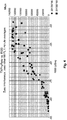
- FIG. 4 shows two sets of measured reference data for IEEE 802.11n 2x2 streams between an AP and a STA, measured at two different days, in an interference-free environment and for different conditions of path loss, that demonstrate this uncertainty: in particular the TrainedPhyRates from AP to STA in a region between a RSSI values of -55 to -75 dBm vary between 70 Mbps and 120 Mbps.
- a remaining problem to solve is therefore to assign the decrease of the TrainedPhyRate, as compared to what can be achieved for a given RSSI in perfect conditions, to either physical effects, i.e. lack of reflections and channel conditions, or to far-end interference, i.e. external interference on the receiver side lowering the Received Signal to Noise and Interference Ratio, for those test measurements that are in this uncertainty zone.
- First step of the analysis is to separate issues at receiver side from CCA related issues.
- rate adaptation algorithm in any Wi-Fi node aims at reducing packet loss by stepping down to lower modulation rates and less spatial streams. If we define "TrainedPhyRate" as the modulation rate that is used when the link is trained, we can approximatively assume that problems on receive side/packet loss is minimal at this PhyRate.
- Further performance loss can be caused by the CCA mechanism blocking the transmitter to send packets. This can be assessed by using the CCA statistics (medium busy/medium busy other Wi-Fi). Actual available performance can be assessed through CCA statistics and knowledge of Trained PhyRate, or through an active test.
- PhysLimitsPhyRate As the boundary between performance lost due to "physics” and performance lost due to interference at receiver side.
- PhysLimitsPhyRate is partly defined by extrapolating what PhyRate would be used in case of the measured signal strength (RSSI) - in the absence of interference. This extrapolation is based on reference measurements in a clean environment - this can be in a conducted set up or in a radiated set up.
- RSSI measured signal strength
- the second factor defining PhysLimitsPhyRate is related to the possibility to set up multiple spatial streams or not. Depending on the environment, presence or absence of multiple reflections/spatial paths, (de-)correlation of the signal seen by the different receivers. To take this into account, we use the measured average number of spatial streams as used by the link under traffic.
- the above method can be improved by additionally performing -before or after the active test- a passive test, which is a monitoring mode during which a data transmission of the CPE device is monitored, to obtain a second set of parameters.
- a passive test which is a monitoring mode during which a data transmission of the CPE device is monitored.
- the decision is made to assign an observed decrease in a measured data rate (TrainedPhyRate) to physics effects or to Far End Interference effects.
- TrainedPhyRate measured data rate
- the active test is needed to fully execute the link and get reliable values of TrainedPhyRate, RSSI etc. This active test will also yield the real, rather than an extrapolated, data rate that can be achieved over this Wi-Fi link.
- CCA statistics like medium availability, glitches, etc., - referring to the analogy that you cannot listen while talking.
- the second set of parameters solves this problem and allows to use the "signatures” observed while sensing the medium to distinguish "Far End Interference" issues from "Physics”.
- the method includes:
- the area between the bottom boundary 83 and the top boundary 82 is called “PurpleRegion", region 86, which is the uncertainty region.
- the method described relies on the availability of correct statistics related to the quality of the Wi-Fi link, such as but not limited to Signal Strength (RSSI) as well as of the Modulation rate (Physical Rate) and the number of Spatial Streams used for a given Wi-Fi link. It is not a trivial task to obtain the correct statistics, as there are power save mechanisms in place that influence the above mentioned parameters in such a way that they cannot be used as such to understand the quality of the Wi-Fi link. E.g. a Wi-Fi implementation can reduce the number of spatial streams and/or the modulation rate to reduce power consumption - rather than in reaction to interference which would prohibit the use of multiple spatial streams and/or of higher modulation rates.
- RSSI Signal Strength
- Physical Rate Physical Rate
- the passive monitoring test takes samples of the above-mentioned parameters on a short time scale, e.g. every second. Rather than taking just the average of the samples taken over a certain interval - averaging is certainly needed to obtain reliable results - a filtered average is used. This means that only those samples are retained for calculating the average that are taken at moment when sufficient traffic is flowing over the link. This can be deduced from the TxRate and RxRate parameters that are also sampled every second. By taking the correct threshold for the TxRate and/or RxRate messurement, the filtered average can avoid the artefacts caused by power save mechanisms, and ensure that only correctly "trained" values of the relevant parameters such as PhyRate, RSSI, and number of spatial streams are considered.
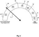
- the obtained results can be displayed for a user on a display of his station 2 by the test application 13 for example as consecutive blocks forming a semi-circle, as shown in figure 6 .
- the data rates as explained with regard to figure 2 define the length of each block.
- a pointer P visualizes the finally attainable data rate 36, which is in this embodiment 23% of the theoretically available data rate of 130 MB/s.
- Each of the blocks include a question mark Q, which can be selected by the user for example by using a mouse or a touchpad. By selecting one of the question marks Q, the user is informed about the problem which causes the throughput loss leading to the contribution of this block and gives an advice for the user, how he can improve the situation. In case of selecting the question mark Q of the block 50, the user is informed that the obtained data rate during the test was only 28 MB/s, 23% of the theoretically maximum rate of 130 MB/s.
Landscapes
- Engineering & Computer Science (AREA)
- Computer Networks & Wireless Communication (AREA)
- Signal Processing (AREA)
- Data Mining & Analysis (AREA)
- Environmental & Geological Engineering (AREA)
- Quality & Reliability (AREA)
- Mobile Radio Communication Systems (AREA)
- Monitoring And Testing Of Transmission In General (AREA)
Claims (15)
- Verfahren zur Analyse einer drahtlosen Verbindung (3) eines Drahtlosknotens einer Nutzergebäudeausrüstung (1), mit
Durchführen eines ersten Tests, während welchem eine Datenübertragung über die drahtlose Verbindung erfolgt, um einen ersten Satz von Parametern zu erhalten, und
Durchführen eines zweiten Tests, welcher ein Überwachungsmodus ist, während dem eine Datenübertragung der drahtlosen Verbindung (3) überwacht wird, um einen zweiten Satz von Parametern zu erhalten,
dadurch gekennzeichnet,
dass der erste Satz von Parametern zumindest eine gemessene Datenrate mit einem Empfangssignalstärken-Indikator (RSSI)-Wert umfasst und der zweite Satz von Parametern zumindest Freikanal-Bewertungsstatistiken umfasst, und wenn die gemessene Datenrate mit dem RSSI-Wert innerhalb der Grenze der Referenzdaten ist, wobei die Referenzdaten zwei Sätze von Datenraten mit RSSI-Werten umfasst, welche zu zwei unterschiedlichen Zeitpunkten in einer störungsfreien Umgebung und für zwei unterschiedliche Bedingungen von Verlustwegen gemessen sind, ein beobachteter Abfall in der gemessenen Datenrate zu physikalischen Effekten oder einer Störung am anderen Ende zugeordnet wird, wobei der beobachtete Abfall in der gemessenen Datenrate einer Störung am anderen Ende zugeordnet wird, wenn die Kanalbewertungsstatistiken der zweiten Parameter das Vorliegen von Störungen aufzeigen. - Verfahren nach Anspruch 1, mit:Abfragen von einem oder mehreren der nachfolgenden Parameter in einem Zeitintervall: RSSI, Modulationsrate und/oder die Anzahl von spatialen Strömen, welche während des zweiten Tests für die drahtlose Verbindung verwendet werden, undBerechnen eines Durchschnitts für diese Parameter über das Testintervall durch Vorsehen eines Filterns von den Parametern, um Fehler aufgrund von Energiespareinrichtungen zu vermeiden.
- Verfahren nach Anspruch 2, mit:
Abfragen der Übertragungsrate und der Empfangsrate in dem Zeitintervall, um den über die Verbindung laufenden Verkehr zu berechnen, und Behalten nur der Parameterwerte Empfangssignalstärke, Modulationsrate und/oder die Anzahl von spatialen Strömen zum Berechnen des Durchschnitts, welcher zu einem Zeitpunkt bestimmt wird, wenn ausreichend Verkehr über die Verbindung läuft. - Verfahren nach Anspruch 2 oder 3,
wobei die Durchschnittsparameter zum Berechnen der maximal möglichen Datenrate für die drahtlose Verbindung verwendet werden, beispielsweise eine WiFi-Übertragung einer vorgegebenen Anordnung mit zwei Vorrichtungen. - Verfahren nach Anspruch 1,
wobei eine maximal erreichbare drahtlose Datenrate durch Bestimmen des Datendurchganges von den Referenzdaten für ein gegebenes gemessenes RSSI und unter Berücksichtigung eines Korrekturfaktors für die Anzahl der vielen spatialen Ströme für einen gewählten Funk-Standard bestimmt wird, welcher für die Übertragung verwendet wird. - Verfahren nach Anspruch 5,
wobei die Anzahl der vielen spatialen Ströme durch Überprüfen der physikalischen Empfangs- und/oder Übertragungsrate an der Zugangspunktseite oder der Stationsseite bestimmt wird. - Verfahren nach Anspruch 5 oder 6,
wobei ein Korrekturfaktor bestimmt wird, um zwischen einer Umgebung und einer Störung unter Berücksichtigung der Anzahl der spatialen Ströme, welche für den Zugangspunkt zu der Stationsverbindung verwendet werden, im Vergleich mit der Anzahl der spatialen Ströme für die Station zu der Zugangspunktverbindung unterscheiden. - Vorrichtung mit einem Prozessor (10), einem Speicher (11) und einem Drahtlosknoten (12), wobei der Prozessor (10) ausgebildet ist, durchzuführen:- einen ersten Test, während welchem eine Datenübertragung über die drahtlose Verbindung erfolgt, um einen ersten Satz von Parametern zu erhalten, und- einen zweiten Test, welcher ein Überwachungsmodus ist, während dem eine Datenübertragung der drahtlosen Verbindung (3) überwacht wird, um einen zweiten Satz von Parametern zu erhalten,dadurch gekennzeichnet,
dass der erste Satz von Parametern zumindest eine gemessene Datenrate mit einem Empfangssignalstärken-Indikator (RSSI)-Wert aufweist, und der zweite Satz von Parametern zumindest Freikanal-Bewertungsstatistiken umfasst, und wenn die gemessene Datenrate mit dem RSSI-Wert innerhalb der Grenze der Referenzdaten ist, wobei die Referenzdaten zwei Sätze von Datenraten mit RSSI-Werten umfassen, welche zu zwei unterschiedlichen Zeitpunkten in einer störungsfreien Umgebung und für zwei unterschiedliche Bedingungen von Verlustwegen gemessen sind, ein beobachteter Abfall in der gemessenen Datenrate zu physikalischen Effekten oder einer Störung am anderen Ende zugeordnet wird, wobei der beobachtete Abfall in der gemessenen Datenrate einer Störung am anderen Ende zugeordnet wird, wenn die Freikanal-Bewertungsstatistiken der zweiten Parameter das Vorliegen von Störungen aufzeigen. - Vorrichtung nach Anspruch 8,
wobei der Prozessor weiter ausgebildet ist zum Abfragen von einem oder mehreren der nachfolgenden Parameter in einem Zeitintervall: RSSI, Modulationsrate und/oder die Anzahl von spatialen Strömen, welche während des zweiten Tests für die drahtlose Verbindung verwendet werden, und
zum Berechnen eines Durchschnitts für diese Parameter über das Testintervall durch Vorsehen eines Filterns von den Parametern, um Fehler aufgrund von Energiespareinrichtungen zu vermeiden. - Vorrichtung nach Anspruch 9,
wobei der Prozessor weiter ausgebildet ist, zum Abfragen der Übertragungsrate und der Empfangsrate in dem Zeitintervall, um den über die Verbindung laufenden Verkehr zu berechnen, und Behalten nur der Parameterwerte Empfangssignalstärke, Modulationsrate und/oder die Anzahl von spatialen Strömen zum Berechnen des Durchschnitts, welcher zu einem Zeitpunkt bestimmt wird, wenn ausreichend Verkehr über die Verbindung läuft. - Vorrichtung nach Anspruch 9 oder 10,
wobei die Durchschnittsparameter zum Berechnen der maximal möglichen Datenrate für die drahtlose Verbindung verwendet werden, beispielsweise eine WiFi-Übertragung einer vorgegebenen Anordnung mit zwei Vorrichtungen. - Vorrichtung nach Anspruch 8,
wobei eine maximal erreichbare drahtlose Datenrate durch Bestimmen des Datendurchganges von den Referenzdaten für ein gegebenes gemessenes RSSI und unter Berücksichtigung eines Korrekturfaktors für die Anzahl der vielen spatialen Ströme für einen gewählten Funk-Standard bestimmt wird, welcher für die Übertragung verwendet wird. - Vorrichtung nach Anspruch 12,
wobei die Anzahl der vielen spatialen Ströme durch Überprüfung der physikalischen Empfangs- und/oder Übertragungsrate an der Zugangspunktseite oder der Stationsseite bestimmt wird. - Nicht-vorübergehendes Programmspeichermedium, welches durch einen Computer lesbar ist und einen ausführbaren Programmcode zum Durchführen eines Verfahrens gemäß einem der Ansprüche 1 bis 7 bei Ausführung auf einem Computer aufweist.
- Anwendung mit einem ausführbaren Programmcode zum Durchführen eines Verfahrens gemäß einem der Ansprüche 1 bis 7 bei Ausführung auf einem Computer.
Priority Applications (1)
| Application Number | Priority Date | Filing Date | Title |
|---|---|---|---|
| EP19190317.8A EP3582536B1 (de) | 2014-12-18 | 2015-12-17 | Verfahren und vorrichtung zur analyse einer drahtlosen verbindung eines wifi-knotens |
Applications Claiming Priority (2)
| Application Number | Priority Date | Filing Date | Title |
|---|---|---|---|
| EP14307074 | 2014-12-18 | ||
| PCT/EP2015/080269 WO2016097172A2 (en) | 2014-12-18 | 2015-12-17 | Method for analysing a wireless link of a wi-fi node, respective circuit performing the method, and application |
Related Child Applications (1)
| Application Number | Title | Priority Date | Filing Date |
|---|---|---|---|
| EP19190317.8A Division EP3582536B1 (de) | 2014-12-18 | 2015-12-17 | Verfahren und vorrichtung zur analyse einer drahtlosen verbindung eines wifi-knotens |
Publications (2)
| Publication Number | Publication Date |
|---|---|
| EP3235286A2 EP3235286A2 (de) | 2017-10-25 |
| EP3235286B1 true EP3235286B1 (de) | 2019-08-07 |
Family
ID=52394055
Family Applications (2)
| Application Number | Title | Priority Date | Filing Date |
|---|---|---|---|
| EP19190317.8A Active EP3582536B1 (de) | 2014-12-18 | 2015-12-17 | Verfahren und vorrichtung zur analyse einer drahtlosen verbindung eines wifi-knotens |
| EP15810732.6A Active EP3235286B1 (de) | 2014-12-18 | 2015-12-17 | Verfahren zur analyse einer drahtlosen verbindung eines wifi-knotens, entsprechende schaltung zur durchführung des verfahrens und anwendung |
Family Applications Before (1)
| Application Number | Title | Priority Date | Filing Date |
|---|---|---|---|
| EP19190317.8A Active EP3582536B1 (de) | 2014-12-18 | 2015-12-17 | Verfahren und vorrichtung zur analyse einer drahtlosen verbindung eines wifi-knotens |
Country Status (6)
| Country | Link |
|---|---|
| US (4) | US10362502B2 (de) |
| EP (2) | EP3582536B1 (de) |
| CN (2) | CN107113640B (de) |
| BR (1) | BR112017013086B1 (de) |
| TW (1) | TW201625030A (de) |
| WO (1) | WO2016097172A2 (de) |
Families Citing this family (13)
| Publication number | Priority date | Publication date | Assignee | Title |
|---|---|---|---|---|
| US10079762B1 (en) * | 2017-04-24 | 2018-09-18 | Teradyne, Inc. | Test communication protocol |
| CN107332715B (zh) * | 2017-08-14 | 2020-10-02 | 飞思达技术(北京)有限公司 | 主动性能测试加被动分流控的网络应用系统及其实施方法 |
| WO2019071546A1 (zh) * | 2017-10-13 | 2019-04-18 | 深圳传音通讯有限公司 | WiFi信号测试方法、终端及计算机可读存储介质 |
| US11258690B1 (en) * | 2017-11-02 | 2022-02-22 | Speedpact Inc. | System and method for testing and/or monitoring broadband internet connectivity |
| US10750388B2 (en) * | 2018-12-19 | 2020-08-18 | Verizon Patent And Licensing Inc. | System and method for qualifying service in multi-spectrum access network |
| CN111385829B (zh) * | 2018-12-27 | 2021-10-29 | 大唐移动通信设备有限公司 | 一种远端干扰的规避方法、系统及装置 |
| JP7131464B2 (ja) * | 2019-04-02 | 2022-09-06 | 日本電信電話株式会社 | 無線通信特性評価方法および無線通信特性評価装置 |
| CN110191483A (zh) * | 2019-07-01 | 2019-08-30 | 深圳勇艺达机器人有限公司 | 一种用于Wifi模组的性能测试系统和方法 |
| CN113133023B (zh) * | 2019-12-31 | 2022-12-27 | 华为技术有限公司 | 通信方法、无线接入点、无线站点及无线局域网系统 |
| CN115499311B (zh) * | 2022-09-15 | 2023-09-01 | 远效科技成果转化服务有限公司 | 一种基于虚拟cpe的资源分配方法及系统 |
| US20240214079A1 (en) * | 2022-12-22 | 2024-06-27 | Netgear, Inc. | Adaptive Machine Learning For Dynamic Wireless Communication Configuration |
| CN119030909A (zh) * | 2023-05-24 | 2024-11-26 | 明泰科技股份有限公司 | 路由效能测试方法 |
| CN117061032B (zh) * | 2023-10-10 | 2023-12-26 | 灿芯技术(深圳)有限公司 | 一种具备CSMA/CA机制的WiFi干扰测试方法及装置 |
Family Cites Families (18)
| Publication number | Priority date | Publication date | Assignee | Title |
|---|---|---|---|---|
| US7206840B2 (en) * | 2001-05-11 | 2007-04-17 | Koninklike Philips Electronics N.V. | Dynamic frequency selection scheme for IEEE 802.11 WLANs |
| US7355997B2 (en) * | 2004-05-07 | 2008-04-08 | Cisco Technology, Inc. | Data rate shifting methods and techniques |
| US7426395B2 (en) | 2005-03-31 | 2008-09-16 | Intel Corporation | Techniques to select data rates for a wireless system |
| US20070063834A1 (en) * | 2005-08-15 | 2007-03-22 | Motorola, Inc. | Method and apparatus to reduce loss or damage to remote control devices |
| US7756059B1 (en) * | 2008-05-19 | 2010-07-13 | Meru Networks | Differential signal-to-noise ratio based rate adaptation |
| US8345560B2 (en) * | 2008-12-12 | 2013-01-01 | At&T Intellectual Property I, Lp | Methods and apparatus to pre-qualify user communities for communication services |
| US8830849B2 (en) | 2010-01-11 | 2014-09-09 | Qualcomm Incorporated | Method and apparatus for detecting transmission signals |
| JP5890435B2 (ja) | 2011-02-14 | 2016-03-22 | トムソン ライセンシングThomson Licensing | 異なる変調速度で送信されるパケットの往復時間を測定することによるWi−Fiコネクティビティのトラブルシューティング |
| EP2739201B1 (de) | 2011-08-03 | 2016-07-06 | Draeger Medical Systems, Inc. | Auf durchsatz basierender aktivmodusauslöser |
| CN102315904B (zh) | 2011-09-05 | 2014-02-19 | 新邮通信设备有限公司 | 一种优化物理上行链路控制信道检测与测量的方法 |
| CN110380933B (zh) * | 2012-07-13 | 2023-04-14 | 阿西亚Spe有限责任公司 | 用于通信链路性能测量的方法和系统 |
| CN104756474B (zh) * | 2012-07-13 | 2019-07-30 | 适应性频谱和信号校正股份有限公司 | 用于通信链路性能估计的方法和系统 |
| US9131392B2 (en) | 2012-08-06 | 2015-09-08 | Wildfire.Exchange, Inc. | Hidden nodes detection |
| US9055459B2 (en) * | 2013-02-07 | 2015-06-09 | Qualcomm Incorporated | Method and system for dual-mode rate control in a wireless communication system |
| CN105230049B (zh) | 2013-03-15 | 2020-01-10 | 鲁库斯无线公司 | 改进客户端在网络各处的分配 |
| JP2015019210A (ja) * | 2013-07-10 | 2015-01-29 | 株式会社東芝 | 監視装置 |
| EP3806399A1 (de) | 2013-09-27 | 2021-04-14 | AirTies Belgium SPRL | Verfahren zum testen einer drahtlosen verbindung eines wifi-knotens und schaltung zur durchführung des verfahrens |
| CN103731858B (zh) * | 2014-01-14 | 2016-08-17 | 宇龙计算机通信科技(深圳)有限公司 | 无线局域网通信设备和无线局域网通信方法 |
-
2015
- 2015-12-11 TW TW104141618A patent/TW201625030A/zh unknown
- 2015-12-17 EP EP19190317.8A patent/EP3582536B1/de active Active
- 2015-12-17 CN CN201580069129.0A patent/CN107113640B/zh active Active
- 2015-12-17 US US15/537,428 patent/US10362502B2/en active Active
- 2015-12-17 CN CN202110637662.XA patent/CN113473519A/zh active Pending
- 2015-12-17 EP EP15810732.6A patent/EP3235286B1/de active Active
- 2015-12-17 BR BR112017013086-6A patent/BR112017013086B1/pt active IP Right Grant
- 2015-12-17 WO PCT/EP2015/080269 patent/WO2016097172A2/en not_active Ceased
-
2019
- 2019-07-23 US US16/519,837 patent/US11129035B2/en active Active
-
2021
- 2021-09-21 US US17/480,769 patent/US12143840B2/en active Active
-
2024
- 2024-11-11 US US18/943,467 patent/US20250142377A1/en active Pending
Non-Patent Citations (1)
| Title |
|---|
| None * |
Also Published As
| Publication number | Publication date |
|---|---|
| EP3235286A2 (de) | 2017-10-25 |
| EP3582536B1 (de) | 2025-10-01 |
| EP3582536C0 (de) | 2025-10-01 |
| CN113473519A (zh) | 2021-10-01 |
| US11129035B2 (en) | 2021-09-21 |
| US20190349800A1 (en) | 2019-11-14 |
| WO2016097172A3 (en) | 2016-08-11 |
| EP3582536A1 (de) | 2019-12-18 |
| US20180270680A1 (en) | 2018-09-20 |
| US10362502B2 (en) | 2019-07-23 |
| CN107113640A (zh) | 2017-08-29 |
| US12143840B2 (en) | 2024-11-12 |
| BR112017013086A2 (pt) | 2018-01-02 |
| US20220007223A1 (en) | 2022-01-06 |
| BR112017013086B1 (pt) | 2023-10-31 |
| WO2016097172A2 (en) | 2016-06-23 |
| US20250142377A1 (en) | 2025-05-01 |
| TW201625030A (zh) | 2016-07-01 |
| CN107113640B (zh) | 2021-06-25 |
Similar Documents
| Publication | Publication Date | Title |
|---|---|---|
| US12143840B2 (en) | Method for analysing a wireless link of a Wi-Fi node, respective circuit performing the method, and application | |
| US12457161B2 (en) | Method for testing a wireless link of a Wi-Fi node, and circuit performing the method | |
| US12074775B2 (en) | Method for predicting a level of QoE of an application intended to be run on a wireless user equipment | |
| US12212989B2 (en) | Method for evaluating a wireless link, respective device, computer program and storage medium | |
| Kim et al. | Realistic modeling of IEEE 802.11 WLAN considering rate adaptation and multi-rate retry |
Legal Events
| Date | Code | Title | Description |
|---|---|---|---|
| STAA | Information on the status of an ep patent application or granted ep patent |
Free format text: STATUS: THE INTERNATIONAL PUBLICATION HAS BEEN MADE |
|
| PUAI | Public reference made under article 153(3) epc to a published international application that has entered the european phase |
Free format text: ORIGINAL CODE: 0009012 |
|
| STAA | Information on the status of an ep patent application or granted ep patent |
Free format text: STATUS: REQUEST FOR EXAMINATION WAS MADE |
|
| 17P | Request for examination filed |
Effective date: 20170615 |
|
| AK | Designated contracting states |
Kind code of ref document: A2 Designated state(s): AL AT BE BG CH CY CZ DE DK EE ES FI FR GB GR HR HU IE IS IT LI LT LU LV MC MK MT NL NO PL PT RO RS SE SI SK SM TR |
|
| AX | Request for extension of the european patent |
Extension state: BA ME |
|
| DAV | Request for validation of the european patent (deleted) | ||
| DAX | Request for extension of the european patent (deleted) | ||
| STAA | Information on the status of an ep patent application or granted ep patent |
Free format text: STATUS: EXAMINATION IS IN PROGRESS |
|
| 17Q | First examination report despatched |
Effective date: 20180710 |
|
| GRAP | Despatch of communication of intention to grant a patent |
Free format text: ORIGINAL CODE: EPIDOSNIGR1 |
|
| STAA | Information on the status of an ep patent application or granted ep patent |
Free format text: STATUS: GRANT OF PATENT IS INTENDED |
|
| RIC1 | Information provided on ipc code assigned before grant |
Ipc: H04L 12/26 20060101ALI20190109BHEP Ipc: H04W 24/08 20090101AFI20190109BHEP |
|
| INTG | Intention to grant announced |
Effective date: 20190122 |
|
| RAP1 | Party data changed (applicant data changed or rights of an application transferred) |
Owner name: INTERDIGITAL CE PATENT HOLDINGS |
|
| GRAS | Grant fee paid |
Free format text: ORIGINAL CODE: EPIDOSNIGR3 |
|
| GRAA | (expected) grant |
Free format text: ORIGINAL CODE: 0009210 |
|
| STAA | Information on the status of an ep patent application or granted ep patent |
Free format text: STATUS: THE PATENT HAS BEEN GRANTED |
|
| RAP1 | Party data changed (applicant data changed or rights of an application transferred) |
Owner name: AIRTIES BELGIUM SPRL |
|
| AK | Designated contracting states |
Kind code of ref document: B1 Designated state(s): AL AT BE BG CH CY CZ DE DK EE ES FI FR GB GR HR HU IE IS IT LI LT LU LV MC MK MT NL NO PL PT RO RS SE SI SK SM TR |
|
| REG | Reference to a national code |
Ref country code: GB Ref legal event code: FG4D |
|
| REG | Reference to a national code |
Ref country code: CH Ref legal event code: EP Ref country code: AT Ref legal event code: REF Ref document number: 1165761 Country of ref document: AT Kind code of ref document: T Effective date: 20190815 |
|
| REG | Reference to a national code |
Ref country code: DE Ref legal event code: R096 Ref document number: 602015035473 Country of ref document: DE |
|
| REG | Reference to a national code |
Ref country code: IE Ref legal event code: FG4D |
|
| REG | Reference to a national code |
Ref country code: NL Ref legal event code: FP |
|
| REG | Reference to a national code |
Ref country code: LT Ref legal event code: MG4D |
|
| PG25 | Lapsed in a contracting state [announced via postgrant information from national office to epo] |
Ref country code: FI Free format text: LAPSE BECAUSE OF FAILURE TO SUBMIT A TRANSLATION OF THE DESCRIPTION OR TO PAY THE FEE WITHIN THE PRESCRIBED TIME-LIMIT Effective date: 20190807 Ref country code: BG Free format text: LAPSE BECAUSE OF FAILURE TO SUBMIT A TRANSLATION OF THE DESCRIPTION OR TO PAY THE FEE WITHIN THE PRESCRIBED TIME-LIMIT Effective date: 20191107 Ref country code: NO Free format text: LAPSE BECAUSE OF FAILURE TO SUBMIT A TRANSLATION OF THE DESCRIPTION OR TO PAY THE FEE WITHIN THE PRESCRIBED TIME-LIMIT Effective date: 20191107 Ref country code: SE Free format text: LAPSE BECAUSE OF FAILURE TO SUBMIT A TRANSLATION OF THE DESCRIPTION OR TO PAY THE FEE WITHIN THE PRESCRIBED TIME-LIMIT Effective date: 20190807 Ref country code: PT Free format text: LAPSE BECAUSE OF FAILURE TO SUBMIT A TRANSLATION OF THE DESCRIPTION OR TO PAY THE FEE WITHIN THE PRESCRIBED TIME-LIMIT Effective date: 20191209 Ref country code: HR Free format text: LAPSE BECAUSE OF FAILURE TO SUBMIT A TRANSLATION OF THE DESCRIPTION OR TO PAY THE FEE WITHIN THE PRESCRIBED TIME-LIMIT Effective date: 20190807 Ref country code: LT Free format text: LAPSE BECAUSE OF FAILURE TO SUBMIT A TRANSLATION OF THE DESCRIPTION OR TO PAY THE FEE WITHIN THE PRESCRIBED TIME-LIMIT Effective date: 20190807 |
|
| REG | Reference to a national code |
Ref country code: AT Ref legal event code: MK05 Ref document number: 1165761 Country of ref document: AT Kind code of ref document: T Effective date: 20190807 |
|
| PG25 | Lapsed in a contracting state [announced via postgrant information from national office to epo] |
Ref country code: AL Free format text: LAPSE BECAUSE OF FAILURE TO SUBMIT A TRANSLATION OF THE DESCRIPTION OR TO PAY THE FEE WITHIN THE PRESCRIBED TIME-LIMIT Effective date: 20190807 Ref country code: LV Free format text: LAPSE BECAUSE OF FAILURE TO SUBMIT A TRANSLATION OF THE DESCRIPTION OR TO PAY THE FEE WITHIN THE PRESCRIBED TIME-LIMIT Effective date: 20190807 Ref country code: ES Free format text: LAPSE BECAUSE OF FAILURE TO SUBMIT A TRANSLATION OF THE DESCRIPTION OR TO PAY THE FEE WITHIN THE PRESCRIBED TIME-LIMIT Effective date: 20190807 Ref country code: RS Free format text: LAPSE BECAUSE OF FAILURE TO SUBMIT A TRANSLATION OF THE DESCRIPTION OR TO PAY THE FEE WITHIN THE PRESCRIBED TIME-LIMIT Effective date: 20190807 Ref country code: GR Free format text: LAPSE BECAUSE OF FAILURE TO SUBMIT A TRANSLATION OF THE DESCRIPTION OR TO PAY THE FEE WITHIN THE PRESCRIBED TIME-LIMIT Effective date: 20191108 Ref country code: IS Free format text: LAPSE BECAUSE OF FAILURE TO SUBMIT A TRANSLATION OF THE DESCRIPTION OR TO PAY THE FEE WITHIN THE PRESCRIBED TIME-LIMIT Effective date: 20191207 |
|
| PG25 | Lapsed in a contracting state [announced via postgrant information from national office to epo] |
Ref country code: RO Free format text: LAPSE BECAUSE OF FAILURE TO SUBMIT A TRANSLATION OF THE DESCRIPTION OR TO PAY THE FEE WITHIN THE PRESCRIBED TIME-LIMIT Effective date: 20190807 Ref country code: PL Free format text: LAPSE BECAUSE OF FAILURE TO SUBMIT A TRANSLATION OF THE DESCRIPTION OR TO PAY THE FEE WITHIN THE PRESCRIBED TIME-LIMIT Effective date: 20190807 Ref country code: DK Free format text: LAPSE BECAUSE OF FAILURE TO SUBMIT A TRANSLATION OF THE DESCRIPTION OR TO PAY THE FEE WITHIN THE PRESCRIBED TIME-LIMIT Effective date: 20190807 Ref country code: AT Free format text: LAPSE BECAUSE OF FAILURE TO SUBMIT A TRANSLATION OF THE DESCRIPTION OR TO PAY THE FEE WITHIN THE PRESCRIBED TIME-LIMIT Effective date: 20190807 Ref country code: EE Free format text: LAPSE BECAUSE OF FAILURE TO SUBMIT A TRANSLATION OF THE DESCRIPTION OR TO PAY THE FEE WITHIN THE PRESCRIBED TIME-LIMIT Effective date: 20190807 Ref country code: IT Free format text: LAPSE BECAUSE OF FAILURE TO SUBMIT A TRANSLATION OF THE DESCRIPTION OR TO PAY THE FEE WITHIN THE PRESCRIBED TIME-LIMIT Effective date: 20190807 |
|
| PG25 | Lapsed in a contracting state [announced via postgrant information from national office to epo] |
Ref country code: SK Free format text: LAPSE BECAUSE OF FAILURE TO SUBMIT A TRANSLATION OF THE DESCRIPTION OR TO PAY THE FEE WITHIN THE PRESCRIBED TIME-LIMIT Effective date: 20190807 Ref country code: CZ Free format text: LAPSE BECAUSE OF FAILURE TO SUBMIT A TRANSLATION OF THE DESCRIPTION OR TO PAY THE FEE WITHIN THE PRESCRIBED TIME-LIMIT Effective date: 20190807 Ref country code: IS Free format text: LAPSE BECAUSE OF FAILURE TO SUBMIT A TRANSLATION OF THE DESCRIPTION OR TO PAY THE FEE WITHIN THE PRESCRIBED TIME-LIMIT Effective date: 20200224 Ref country code: SM Free format text: LAPSE BECAUSE OF FAILURE TO SUBMIT A TRANSLATION OF THE DESCRIPTION OR TO PAY THE FEE WITHIN THE PRESCRIBED TIME-LIMIT Effective date: 20190807 |
|
| REG | Reference to a national code |
Ref country code: DE Ref legal event code: R097 Ref document number: 602015035473 Country of ref document: DE |
|
| PLBE | No opposition filed within time limit |
Free format text: ORIGINAL CODE: 0009261 |
|
| STAA | Information on the status of an ep patent application or granted ep patent |
Free format text: STATUS: NO OPPOSITION FILED WITHIN TIME LIMIT |
|
| PG2D | Information on lapse in contracting state deleted |
Ref country code: IS |
|
| REG | Reference to a national code |
Ref country code: CH Ref legal event code: PL |
|
| 26N | No opposition filed |
Effective date: 20200603 |
|
| REG | Reference to a national code |
Ref country code: BE Ref legal event code: MM Effective date: 20191231 |
|
| PG25 | Lapsed in a contracting state [announced via postgrant information from national office to epo] |
Ref country code: MC Free format text: LAPSE BECAUSE OF FAILURE TO SUBMIT A TRANSLATION OF THE DESCRIPTION OR TO PAY THE FEE WITHIN THE PRESCRIBED TIME-LIMIT Effective date: 20190807 Ref country code: SI Free format text: LAPSE BECAUSE OF FAILURE TO SUBMIT A TRANSLATION OF THE DESCRIPTION OR TO PAY THE FEE WITHIN THE PRESCRIBED TIME-LIMIT Effective date: 20190807 |
|
| PG25 | Lapsed in a contracting state [announced via postgrant information from national office to epo] |
Ref country code: IE Free format text: LAPSE BECAUSE OF NON-PAYMENT OF DUE FEES Effective date: 20191217 Ref country code: LU Free format text: LAPSE BECAUSE OF NON-PAYMENT OF DUE FEES Effective date: 20191217 |
|
| PG25 | Lapsed in a contracting state [announced via postgrant information from national office to epo] |
Ref country code: LI Free format text: LAPSE BECAUSE OF NON-PAYMENT OF DUE FEES Effective date: 20191231 Ref country code: BE Free format text: LAPSE BECAUSE OF NON-PAYMENT OF DUE FEES Effective date: 20191231 Ref country code: CH Free format text: LAPSE BECAUSE OF NON-PAYMENT OF DUE FEES Effective date: 20191231 |
|
| PG25 | Lapsed in a contracting state [announced via postgrant information from national office to epo] |
Ref country code: CY Free format text: LAPSE BECAUSE OF FAILURE TO SUBMIT A TRANSLATION OF THE DESCRIPTION OR TO PAY THE FEE WITHIN THE PRESCRIBED TIME-LIMIT Effective date: 20190807 |
|
| PG25 | Lapsed in a contracting state [announced via postgrant information from national office to epo] |
Ref country code: HU Free format text: LAPSE BECAUSE OF FAILURE TO SUBMIT A TRANSLATION OF THE DESCRIPTION OR TO PAY THE FEE WITHIN THE PRESCRIBED TIME-LIMIT; INVALID AB INITIO Effective date: 20151217 Ref country code: MT Free format text: LAPSE BECAUSE OF FAILURE TO SUBMIT A TRANSLATION OF THE DESCRIPTION OR TO PAY THE FEE WITHIN THE PRESCRIBED TIME-LIMIT Effective date: 20190807 |
|
| PG25 | Lapsed in a contracting state [announced via postgrant information from national office to epo] |
Ref country code: MK Free format text: LAPSE BECAUSE OF FAILURE TO SUBMIT A TRANSLATION OF THE DESCRIPTION OR TO PAY THE FEE WITHIN THE PRESCRIBED TIME-LIMIT Effective date: 20190807 |
|
| PGFP | Annual fee paid to national office [announced via postgrant information from national office to epo] |
Ref country code: DE Payment date: 20241210 Year of fee payment: 10 |
|
| PGFP | Annual fee paid to national office [announced via postgrant information from national office to epo] |
Ref country code: NL Payment date: 20241214 Year of fee payment: 10 |
|
| PGFP | Annual fee paid to national office [announced via postgrant information from national office to epo] |
Ref country code: GB Payment date: 20241212 Year of fee payment: 10 |
|
| PGFP | Annual fee paid to national office [announced via postgrant information from national office to epo] |
Ref country code: FR Payment date: 20241223 Year of fee payment: 10 |
|
| PGFP | Annual fee paid to national office [announced via postgrant information from national office to epo] |
Ref country code: TR Payment date: 20241127 Year of fee payment: 10 |