EP3234385B1 - Remote control assembly - Google Patents
Remote control assembly Download PDFInfo
- Publication number
- EP3234385B1 EP3234385B1 EP14828613.1A EP14828613A EP3234385B1 EP 3234385 B1 EP3234385 B1 EP 3234385B1 EP 14828613 A EP14828613 A EP 14828613A EP 3234385 B1 EP3234385 B1 EP 3234385B1
- Authority
- EP
- European Patent Office
- Prior art keywords
- notches
- wire
- remote control
- row
- control assembly
- Prior art date
- Legal status (The legal status is an assumption and is not a legal conclusion. Google has not performed a legal analysis and makes no representation as to the accuracy of the status listed.)
- Active
Links
Images



Classifications
-
- F—MECHANICAL ENGINEERING; LIGHTING; HEATING; WEAPONS; BLASTING
- F16—ENGINEERING ELEMENTS AND UNITS; GENERAL MEASURES FOR PRODUCING AND MAINTAINING EFFECTIVE FUNCTIONING OF MACHINES OR INSTALLATIONS; THERMAL INSULATION IN GENERAL
- F16C—SHAFTS; FLEXIBLE SHAFTS; ELEMENTS OR CRANKSHAFT MECHANISMS; ROTARY BODIES OTHER THAN GEARING ELEMENTS; BEARINGS
- F16C1/00—Flexible shafts; Mechanical means for transmitting movement in a flexible sheathing
- F16C1/10—Means for transmitting linear movement in a flexible sheathing, e.g. "Bowden-mechanisms"
-
- F—MECHANICAL ENGINEERING; LIGHTING; HEATING; WEAPONS; BLASTING
- F16—ENGINEERING ELEMENTS AND UNITS; GENERAL MEASURES FOR PRODUCING AND MAINTAINING EFFECTIVE FUNCTIONING OF MACHINES OR INSTALLATIONS; THERMAL INSULATION IN GENERAL
- F16C—SHAFTS; FLEXIBLE SHAFTS; ELEMENTS OR CRANKSHAFT MECHANISMS; ROTARY BODIES OTHER THAN GEARING ELEMENTS; BEARINGS
- F16C1/00—Flexible shafts; Mechanical means for transmitting movement in a flexible sheathing
- F16C1/10—Means for transmitting linear movement in a flexible sheathing, e.g. "Bowden-mechanisms"
- F16C1/108—Reducing or controlling of vibrations, e.g. by resilient damping of noise
-
- F—MECHANICAL ENGINEERING; LIGHTING; HEATING; WEAPONS; BLASTING
- F16—ENGINEERING ELEMENTS AND UNITS; GENERAL MEASURES FOR PRODUCING AND MAINTAINING EFFECTIVE FUNCTIONING OF MACHINES OR INSTALLATIONS; THERMAL INSULATION IN GENERAL
- F16C—SHAFTS; FLEXIBLE SHAFTS; ELEMENTS OR CRANKSHAFT MECHANISMS; ROTARY BODIES OTHER THAN GEARING ELEMENTS; BEARINGS
- F16C1/00—Flexible shafts; Mechanical means for transmitting movement in a flexible sheathing
- F16C1/26—Construction of guiding-sheathings or guiding-tubes
-
- F—MECHANICAL ENGINEERING; LIGHTING; HEATING; WEAPONS; BLASTING
- F16—ENGINEERING ELEMENTS AND UNITS; GENERAL MEASURES FOR PRODUCING AND MAINTAINING EFFECTIVE FUNCTIONING OF MACHINES OR INSTALLATIONS; THERMAL INSULATION IN GENERAL
- F16C—SHAFTS; FLEXIBLE SHAFTS; ELEMENTS OR CRANKSHAFT MECHANISMS; ROTARY BODIES OTHER THAN GEARING ELEMENTS; BEARINGS
- F16C2208/00—Plastics; Synthetic resins, e.g. rubbers
- F16C2208/20—Thermoplastic resins
- F16C2208/30—Fluoropolymers
- F16C2208/32—Polytetrafluorethylene [PTFE]
-
- F—MECHANICAL ENGINEERING; LIGHTING; HEATING; WEAPONS; BLASTING
- F16—ENGINEERING ELEMENTS AND UNITS; GENERAL MEASURES FOR PRODUCING AND MAINTAINING EFFECTIVE FUNCTIONING OF MACHINES OR INSTALLATIONS; THERMAL INSULATION IN GENERAL
- F16C—SHAFTS; FLEXIBLE SHAFTS; ELEMENTS OR CRANKSHAFT MECHANISMS; ROTARY BODIES OTHER THAN GEARING ELEMENTS; BEARINGS
- F16C2208/00—Plastics; Synthetic resins, e.g. rubbers
- F16C2208/20—Thermoplastic resins
- F16C2208/60—Polyamides [PA]
-
- F—MECHANICAL ENGINEERING; LIGHTING; HEATING; WEAPONS; BLASTING
- F16—ENGINEERING ELEMENTS AND UNITS; GENERAL MEASURES FOR PRODUCING AND MAINTAINING EFFECTIVE FUNCTIONING OF MACHINES OR INSTALLATIONS; THERMAL INSULATION IN GENERAL
- F16C—SHAFTS; FLEXIBLE SHAFTS; ELEMENTS OR CRANKSHAFT MECHANISMS; ROTARY BODIES OTHER THAN GEARING ELEMENTS; BEARINGS
- F16C2208/00—Plastics; Synthetic resins, e.g. rubbers
- F16C2208/20—Thermoplastic resins
- F16C2208/76—Polyolefins, e.g. polyproylene [PP]
- F16C2208/78—Polyethylene [PE], e.g. ultra-high molecular weight polyethylene [UHMWPE]
-
- Y—GENERAL TAGGING OF NEW TECHNOLOGICAL DEVELOPMENTS; GENERAL TAGGING OF CROSS-SECTIONAL TECHNOLOGIES SPANNING OVER SEVERAL SECTIONS OF THE IPC; TECHNICAL SUBJECTS COVERED BY FORMER USPC CROSS-REFERENCE ART COLLECTIONS [XRACs] AND DIGESTS
- Y10—TECHNICAL SUBJECTS COVERED BY FORMER USPC
- Y10T—TECHNICAL SUBJECTS COVERED BY FORMER US CLASSIFICATION
- Y10T74/00—Machine element or mechanism
- Y10T74/20—Control lever and linkage systems
- Y10T74/20396—Hand operated
- Y10T74/20402—Flexible transmitter [e.g., Bowden cable]
- Y10T74/2045—Flexible transmitter [e.g., Bowden cable] and sheath support, connector, or anchor
-
- Y—GENERAL TAGGING OF NEW TECHNOLOGICAL DEVELOPMENTS; GENERAL TAGGING OF CROSS-SECTIONAL TECHNOLOGIES SPANNING OVER SEVERAL SECTIONS OF THE IPC; TECHNICAL SUBJECTS COVERED BY FORMER USPC CROSS-REFERENCE ART COLLECTIONS [XRACs] AND DIGESTS
- Y10—TECHNICAL SUBJECTS COVERED BY FORMER USPC
- Y10T—TECHNICAL SUBJECTS COVERED BY FORMER US CLASSIFICATION
- Y10T74/00—Machine element or mechanism
- Y10T74/20—Control lever and linkage systems
- Y10T74/20396—Hand operated
- Y10T74/20402—Flexible transmitter [e.g., Bowden cable]
- Y10T74/20456—Specific cable or sheath structure
Definitions
- the present invention generally relates to a remote control assembly.
- remote control assemblies have been developed for many applications. Typical use of remote control assemblies includes, but is not limited to, automotive applications such as control of automatic transmissions, accelerators, clutches, cruise controls, HVAC vents, and the like. Many of these applications include the transmission of motion in a curved path by a flexible transmitting core element slidably disposed in a conduit. These conduits typically include a liner, a sheath, and at least one wire for reinforcing the sheath about the liner.
- the wires move relative to one another, the sheath, and the liner.
- Current designs of the wires help reduce, but may not completely reduce, movement of the wires and/or movement of the sheath.
- current designs of wires may deform the sheath and/or the liner when the wires move relative to the sheath.
- US 5 129 861 A discloses a remote control assembly, said remote control assembly comprising: a sheath having a longitudinal axis along a length thereof and defining an interior; a liner disposed within said interior and coupled to said sheath; and a wire having an outer surface with said wire disposed between and coupled to said sheath and said liner; wherein said outer surface of said wire defines a plurality of blocks separated into a first group and a second group of blocks with each block within each of said first and second groups defining a first distance therebetween substantially along said longitudinal axis.
- a remote control assembly includes a sheath having a longitudinal axis along a length thereof and defining an interior.
- a liner is disposed within the interior and coupled to the sheath.
- a wire has an outer surface and the wire disposed between and coupled to the sheath and the liner.
- the outer surface of the wire defines a plurality of notches separated into a first group of notches and a second group of notches. Each notch within each of the first and second groups defines a first distance therebetween substantially along the longitudinal axis.
- the first group of notches and the second group of notches define a second distance therebetween along the longitudinal axis. The second distance is greater than the first distance.
- a remote control assembly 20 is shown.
- Typical use of remote control assemblies includes, but is not limited to, automotive applications such as control of automatic transmissions, accelerators, clutches, cruise controls, HVAC vents, and the like.
- the remote control assembly includes a sheath 22 defining an interior.
- the sheath 22 has an outer face 24, a length 26, and a longitudinal axis A extending along the length 26.
- the sheath 22 is typically comprised of organic polymer material. Examples of suitable organic polymer materials for the sheath 22 include, but are not limited to, nylon or polyamide nylon.
- the remote control assembly 20 additionally includes a liner 28 disposed within the interior of the sheath 22 and coupled to the sheath 22.
- the liner 28 has an exterior surface 30, and defines an opening.
- the liner 28 is typically comprised of organic polymer material. Examples of suitable organic polymer materials for the liner 28 include, but are not limited to, polytetrafluoroethylene or high-density polyethylene. However, other suitable materials may be used for the liner 28 to ensure flexibility and provide low friction support, as described in further detail below.
- the remote control assembly 20 additionally includes a core element 32 disposed and moveable within the opening of the liner 28.
- the core element 32 transmits motion along the longitudinal axis A.
- the core element 32 may take various forms, but is shown in the Figures as a metal wire element that is attachable to control members for transmitting motion therebetween.
- the liner 28, as mentioned above, ensures flexibility and low friction support to permit the core element 32 to slidably move therein.
- the remote control assembly 20 additionally includes at least one wire 34 having a length and an outer surface 36.
- the sheath 22, the liner 28, and the wire 34 collectively form a conduit 38.
- the remote control assembly 20 further includes fittings 40 for supporting the conduit 38 therebetween.
- the fittings 40 may be fitted to the conduit 38 in any suitable manner, such as, but not limited to, overmolding to mechanically interlock the fittings 40 to the sheath 22 of the conduit 38 or using traditional fasteners without departing from the nature of the present invention.
- the fittings 40 When the fittings 40 are overmolded onto the sheath 22 of the conduit 38, the fittings 40 may be comprised of polymeric or plastic materials; for example, nylon, Teflon, synthetic elastomers, polyvinyls, polyethylene, polypropylene, or their copolymers. It is to be appreciated that when the fittings 40 are fastened to the sheath 22 of the conduit 38 using traditional fasterners or any other suitable ways, the fittings 40 may comprise of a material other than the polymeric or plastic materials listed above.
- conduit 38 shown throughout the Figures includes three wires 34, it is to be appreciated that the conduit may include any number of wires 34 without departing from the nature of the present invention. It is also to be appreciated that even though the wire 34 is generally referred to as a single wire 34 throughout the specification, the description of the wire 34 also refers to contemplates embodiments in which multiple wires 34 are used.
- the wire 34 is disposed between and coupled to the sheath 22 and the liner 28. As best shown in Figure 4 , the outer surface 36 of the wire is encapsulated by the sheath 22 with a portion of the outer surface 36 abutting the liner 28.
- the length of the wire 34 is substantially along the longitudinal axis A of the sheath 22, and the wire 34 is substantially straight about the longitudinal axis A. Said differently, the length of the wire 34 spans along the longitudinal axis A such that the wire 34 maintains a continuous radial space from the longitudinal axis A. It is to be appreciated that the wire 34 may not be continuously radially spaced from the longitudinal axis A, for example, due to inconsistencies protruding from the exterior surface 30 of the liner 28 without departing from the nature of the present invention.
- the wire 34 helically wraps around the exterior surface 30 of the liner 28, as best shown in Figures 2 - 4 .
- the pitch of the wire 34 is between 20 cm and 30 cm (8 and 12 inches).
- the pitch of the wire 34 may be less than 20 cm (8 inches) or greater than 30 cm (12 inches) without departing from the nature of the present invention.
- the wire 34 remains in continuous contact with the exterior surface 30 of the liner 28.
- the helical wrapping of the wire 34 around the exterior surface 30 of the liner 28 provides strength and support such that the conduit 38 may bend with respect to the core element 32 without damaging the conduit 38.
- the outer surface 36 of the wire defines a plurality of notches 42.
- the plurality of notches 42 are separated into a first group of notches 44 and a second group of notches 46. It is to be appreciated that the plurality of notches 42 may be separated into two or more groups of notches 42 without departing from the nature of the present invention.
- the outer surface 36 of the wire 34 may define three or more groups of notches 42 along the length of the wire 34. Depending on the application of the remote control assembly 20, the wire 34 may need to be a different length, which will affect the number of groups of notches 42.
- Each notch 42 within the first group of notches 44 and the second group of notches 46 defines a first distance 48 between one another along the longitudinal axis A.
- the first distance 48 is approximately four millimeters.
- the first distance 48 may vary depending on many factors, such as the environment and the size of the liner 28 and the sheath 22 and may, therefore, be greater or less than four millimeters.
- the first group of notches 44 and the second group of notches 46 define a second distance 50 between one another along the longitudinal axis A.
- the second distance 50 is approximately 152 millimeters.
- the second distance 50 may vary depending on many factors, such as the environment and the size of the liner 28 and the sheath 22 and may, therefore, be greater or less than 152 millimeters.
- the second distance 50 must be greater than the first distance 48 in each embodiment.
- outer surface 36 of the wire 34 is substantially smooth along the length of the wire 34.
- the wire 34 is typically free of protrusions extending beyond the outer surface 36 of the wire 34 toward the outer face 24 of the sheath 22.
- the notches 42 are formed entirely below the outer surface 36 of the wire 34 such that wire 34 is free of protrusions extending beyond the outer surface 36 of the wire 34 toward the outer face 24 of the sheath 22.
- the wire 34 provides continuous support of the liner 28, which may, in turn, reduce variation of an inner diameter of the liner 28.
- portions of the outer surface 36 may define notches 42 that protrude radially from the rest of the outer surface 36 toward the outer face 24 of the sheath 22, as described in further detail below.
- the first group of notches 44 has a first row of notches 52 and a second row of notches 54 radially spaced from the first row of notches 52 along the outer surface 36 of the wire 34.
- the first row of notches 52 and the second row of notches 54 may be radially spaced from one another at any desired angle.
- the first row of notches 52 are radially spaced 180 degrees from the second row of notches 54.
- the first row of notches 52 and the second row of notches 54 may be radially spaced less than 180 degrees from one another without departing from the nature of the present invention.
- the wire XX may define more than a first row of notches 52 and a second row of notches 54 without departing from the nature of the present invention.
- the wire 34 may define three or more rows of notches 42 that are radially spaced from one another about the longitudinal axis A without departing from the nature of the present invention.
- each notch 42 of the first row of notches 52 is offset with respect to and along the longitudinal axis A from each notch 42 of the second row of notches 54, as best shown in Figures 6 and 7 .
- Offsetting the first row of notches 52 from the second row of notches 54 helps the wire 34 retain structural integrity. If the first row of notches 52 and the second row of notches 54 were to align with one another with respect to and along the longitudinal axis A, the diameter of the wire 34 would decrease where the notches 42 of the first row of notches 52 and the second row of notches 54 aligned along the longitudinal axis A.
- the wire 34 typically has at least one notches 42 of the first row of notches 52 disposed between at least two notches 42 of the second row of notches 54, as also best shown in Figures 6 and 7 .
- Each notch 42 of the first row of notches 52 is equidistant from one another along the longitudinal axis A.
- each notch 42 of the second row of notches 54 are equidistant from one another along the longitudinal axis A.
- the second group of notches 46 also has a first row of notches 52 and a second row of notches 54 radially spaced from the first row of notches 52 along the outer surface 36 of the wire 34.
- the first row of notches 52 of both the first group of notches 44 and the second group of notches 46 correspond to one another.
- first row of notches 52 of the first group of notches 44 and the first row of notches 52 of the second group of notches 46 align with one another along the outer surface 36 and along the length of the wire 34.
- second row of notches 54 of the first group of notches 44 and the second row of notches 54 of the second group of notches 46 align with one another along the outer surface 36 and along the length of the wire 34.
- each notch 42 of the first row of notches 52 of the second group of notches 46 is equidistant from the other notches 42 along the longitudinal axis A
- each notch of the second row of notches 54 of the second group of notches 46 is equidistant from the other notches along the longitudinal axis A.
- the plurality of notches 42 may be separated into two or more groups of notches 42, which, in turn, results in two or more first rows of notches 42 and two or more second rows of notches 42.
- a portion of the sheath 22 is disposed within the notches 42 of the wire 34.
- the notches 42 have an inner surface 56 defining a cavity 58 with the portion of the sheath 22 entirely filling the cavity 58.
- the portion of the sheath 22 disposed within the notches 42 of the wire 34 secures the wire 34 to the sheath 22.
- the sheath 22 is typically overmolded onto the wire 34, which allows the portion of the sheath 22 to be disposed within the notches 42 of the wire 34.
- an intersection of the inner surface 56 of the notches 42 and the outer surface 36 of the wire 34 form an oval-shaped perimeter 60. It is to be appreciated that the inner surface 56 of the notches 42 and the outer surface 36 of the wire 34 may form any shaped perimeter, such as, but not limited to, circular or square, without departing from the nature of the present invention.
- the intersection of the inner surface 56 of the notches 42 and the outer surface 36 of the wire 34 form and define a ridge 62.
- the ridge 62 is a right angle.
- the inner surface 56 of the notches 42 is perpendicular to the longitudinal axis A at the intersection and the outer surface 36 of the wire 34 is parallel to the longitudinal axis A at the intersection such that the inner surface 56 and the outer surface 36 form a right angle.
- the ridge 62 formed by the intersection of the inner surface 56 and the outer surface 36 may protrude radially from the outer surface 36 toward the outer face 24 of the sheath 22.
- the ridge 62 may be a plurality of teeth extending from the outer surface 36 of the wire 34 toward the outer face 24 of the sheath 22.
- the inner surface 56 of the notches 42 is typically substantially smooth, as best shown in Figures 7 , 9 , and 10 . Said differently, the inner surface 56 is free of protrusions extending beyond the inner surface 56 toward the outer surface 36 of the wire 34. However, it is to be appreciated that in other embodiments the inner surface 56 of the wire 34 may define a plurality of cuts 64, as shown in Figures 11 and 12 . As shown in Figure 12 , a portion of the sheath 22 entirely fills the cuts 64 defined within the inner surface 56 of the wire 34.
- the plurality of notches 42 helps the wire 34 to remain in continuous engagement with the sheath 22.
- the continuous engagement of the wire 34 to with the sheath 22 helps reduce or eliminate the risk of the sheath 22 shrinking away from the fittings 40 after installation, which is often referred to as shrinkback.
- shrinkback In circumstances in which shrinkback occurs, it may make installation of the fittings 40 onto the conduit 38 more difficult.
- a smaller portion of the outer surface 36 of the sheath 22 is available for coupling to the fittings 40 when shrinkback occurs.
- exposed wires 34 in the conduit can cause damage to molds in which ends of the sheath 22 are disposed for molding the fittings 40 thereabout.
- the wire 34 is arranged such that neither the first row of notches 52 nor the second row of notches 54 face the liner 28, as best shown in Figures 3 and 5 .
- the sheath 22 fills both the first row of notches 52 and the second row of notches 54, as shown in Figure 5 .
- the wire 34 is better secured to the sheath 22.
- the other one of the first row of notches 52 or the second row of notches 54 is filled with the portion of the sheath 22 to secure the wire to the sheath 22.
- This is advantageous and provides ease of manufacturing the conduit 38 since the sheath 22 will fill at least a portion of the plurality of notches 42, regardless of the orientation of the wire 34 and, in turn, the notches 42 with respect to the liner 28.
- the liner 28 may have a thickness that is greater or less than the thickness shown throughout the Figures.
- the sheath 22 may have a thickness that is greater or less than the thickness as shown throughout the Figures.
- the wire 34 may have a diameter that is greater or less than the thickness shown throughout the Figures.
- the notches 42 of the wire 34 may be defined further into the wire 34 such that a depth of the notches 42 may be a greater portion of the diameter of the wire 34 than is shown throughout the Figures, or the notches 42 of the wire 34 may be defined less into the wire 34 such that the depth of the notches 42 may be smaller portion of the diameter of the wire than is shown throughout the Figures.
- the liner 28 may have a thickness that is greater or less than the thickness shown throughout the Figures.
- the sheath 22 may have a thickness that is greater or less than the thickness as shown throughout the Figures.
- the wire 34 may have a diameter that is greater or less than the thickness shown throughout the Figures.
- the notches 42 of the wire 34 may be defined further into the wire 34 such that a depth of the notches 42 may be a greater portion of the diameter of the wire 34 than is shown throughout the Figures, or the notches 42 of the wire 34 may be defined less into the wire 34 such that the depth of the notches 42 may be smaller portion of the diameter of the wire than is shown throughout the Figures.
Landscapes
- Engineering & Computer Science (AREA)
- General Engineering & Computer Science (AREA)
- Health & Medical Sciences (AREA)
- Oral & Maxillofacial Surgery (AREA)
- Mechanical Engineering (AREA)
- Flexible Shafts (AREA)
- Mechanical Control Devices (AREA)
- Selective Calling Equipment (AREA)
Description
- The present invention generally relates to a remote control assembly.
- Various remote control assemblies have been developed for many applications. Typical use of remote control assemblies includes, but is not limited to, automotive applications such as control of automatic transmissions, accelerators, clutches, cruise controls, HVAC vents, and the like. Many of these applications include the transmission of motion in a curved path by a flexible transmitting core element slidably disposed in a conduit. These conduits typically include a liner, a sheath, and at least one wire for reinforcing the sheath about the liner.
- During normal operation of the remote control assembly, the wires move relative to one another, the sheath, and the liner. Current designs of the wires help reduce, but may not completely reduce, movement of the wires and/or movement of the sheath. Furthermore, current designs of wires may deform the sheath and/or the liner when the wires move relative to the sheath.
-
US 5 129 861 A discloses a remote control assembly, said remote control assembly comprising: a sheath having a longitudinal axis along a length thereof and defining an interior; a liner disposed within said interior and coupled to said sheath; and a wire having an outer surface with said wire disposed between and coupled to said sheath and said liner; wherein said outer surface of said wire defines a plurality of blocks separated into a first group and a second group of blocks with each block within each of said first and second groups defining a first distance therebetween substantially along said longitudinal axis. - As such, there remains an opportunity to design a wire that further reduces movement of the wires with respect to one another, the sheath, and the liner. Also, there remains an opportunity to design a wire that eliminates deformation of the sheath and/or the liner.
- A remote control assembly includes a sheath having a longitudinal axis along a length thereof and defining an interior. A liner is disposed within the interior and coupled to the sheath. A wire has an outer surface and the wire disposed between and coupled to the sheath and the liner. The outer surface of the wire defines a plurality of notches separated into a first group of notches and a second group of notches. Each notch within each of the first and second groups defines a first distance therebetween substantially along the longitudinal axis. The first group of notches and the second group of notches define a second distance therebetween along the longitudinal axis. The second distance is greater than the first distance.
- Other advantages of the present invention will be readily appreciated, as the same becomes better understood by reference to the following detailed description when considered in connection with the accompanying drawings.
-
Figure 1 is a perspective view of a remote control assembly. -
Figure 2 is a side view of a conduit of the remote control assembly with a sheath of the conduit shown in cross-section. -
Figure 3 is a side view of a portion the conduit shown inFigure 2 with the sheath shown in cross-section. -
Figure 4 is a perspective view of a portion of the conduit with a portion of the sheath removed. -
Figure 5 is a front cross-sectional view of the conduit. -
Figure 6 is a top view of a wire of the conduit defining notches therein. -
Figure 7 is a side-view of the wire of the conduit defining notches therein. -
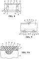
Figure 8 is a top view of a portion of the wire shown inFigure 6 . -
Figure 9 is a side view of a portion of the wire shown inFigure 7 . -
Figure 10 is a side view of a portion of the conduit shown inFigure 3 with the sheath shown in cross-sectional. -
Figure 11 is a side view of another embodiment of the wire defining cuts within the notches. -
Figure 12 is a side view of a portion of the wire shown inFigure 11 . - With reference to the Figures, wherein like numerals indicate like parts throughout the several views, a
remote control assembly 20 is shown. Typical use of remote control assemblies includes, but is not limited to, automotive applications such as control of automatic transmissions, accelerators, clutches, cruise controls, HVAC vents, and the like. - As best shown in
Figures 1 - 3 , the remote control assembly includes asheath 22 defining an interior. Thesheath 22 has anouter face 24, alength 26, and a longitudinal axis A extending along thelength 26. Thesheath 22 is typically comprised of organic polymer material. Examples of suitable organic polymer materials for thesheath 22 include, but are not limited to, nylon or polyamide nylon. - The
remote control assembly 20 additionally includes aliner 28 disposed within the interior of thesheath 22 and coupled to thesheath 22. Theliner 28 has anexterior surface 30, and defines an opening. Theliner 28 is typically comprised of organic polymer material. Examples of suitable organic polymer materials for theliner 28 include, but are not limited to, polytetrafluoroethylene or high-density polyethylene. However, other suitable materials may be used for theliner 28 to ensure flexibility and provide low friction support, as described in further detail below. - The
remote control assembly 20 additionally includes acore element 32 disposed and moveable within the opening of theliner 28. Thecore element 32 transmits motion along the longitudinal axis A. Thecore element 32 may take various forms, but is shown in the Figures as a metal wire element that is attachable to control members for transmitting motion therebetween. Theliner 28, as mentioned above, ensures flexibility and low friction support to permit thecore element 32 to slidably move therein. - The
remote control assembly 20 additionally includes at least onewire 34 having a length and anouter surface 36. Thesheath 22, theliner 28, and thewire 34 collectively form aconduit 38. Theremote control assembly 20 further includesfittings 40 for supporting theconduit 38 therebetween. Thefittings 40 may be fitted to theconduit 38 in any suitable manner, such as, but not limited to, overmolding to mechanically interlock thefittings 40 to thesheath 22 of theconduit 38 or using traditional fasteners without departing from the nature of the present invention. When thefittings 40 are overmolded onto thesheath 22 of theconduit 38, thefittings 40 may be comprised of polymeric or plastic materials; for example, nylon, Teflon, synthetic elastomers, polyvinyls, polyethylene, polypropylene, or their copolymers. It is to be appreciated that when thefittings 40 are fastened to thesheath 22 of theconduit 38 using traditional fasterners or any other suitable ways, thefittings 40 may comprise of a material other than the polymeric or plastic materials listed above. - Although the
conduit 38 shown throughout the Figures includes threewires 34, it is to be appreciated that the conduit may include any number ofwires 34 without departing from the nature of the present invention. It is also to be appreciated that even though thewire 34 is generally referred to as asingle wire 34 throughout the specification, the description of thewire 34 also refers to contemplates embodiments in whichmultiple wires 34 are used. - The
wire 34 is disposed between and coupled to thesheath 22 and theliner 28. As best shown inFigure 4 , theouter surface 36 of the wire is encapsulated by thesheath 22 with a portion of theouter surface 36 abutting theliner 28. The length of thewire 34 is substantially along the longitudinal axis A of thesheath 22, and thewire 34 is substantially straight about the longitudinal axis A. Said differently, the length of thewire 34 spans along the longitudinal axis A such that thewire 34 maintains a continuous radial space from the longitudinal axis A. It is to be appreciated that thewire 34 may not be continuously radially spaced from the longitudinal axis A, for example, due to inconsistencies protruding from theexterior surface 30 of theliner 28 without departing from the nature of the present invention. - The
wire 34 helically wraps around theexterior surface 30 of theliner 28, as best shown inFigures 2 - 4 . Typically, the pitch of thewire 34 is between 20 cm and 30 cm (8 and 12 inches). However, it is to be appreciated that the pitch of thewire 34 may be less than 20 cm (8 inches) or greater than 30 cm (12 inches) without departing from the nature of the present invention. Thewire 34 remains in continuous contact with theexterior surface 30 of theliner 28. The helical wrapping of thewire 34 around theexterior surface 30 of theliner 28 provides strength and support such that theconduit 38 may bend with respect to thecore element 32 without damaging theconduit 38. - As best shown in
Figures 6 and 7 , theouter surface 36 of the wire defines a plurality ofnotches 42. The plurality ofnotches 42 are separated into a first group ofnotches 44 and a second group ofnotches 46. It is to be appreciated that the plurality ofnotches 42 may be separated into two or more groups ofnotches 42 without departing from the nature of the present invention. For example, theouter surface 36 of thewire 34 may define three or more groups ofnotches 42 along the length of thewire 34. Depending on the application of theremote control assembly 20, thewire 34 may need to be a different length, which will affect the number of groups ofnotches 42. - Each
notch 42 within the first group ofnotches 44 and the second group ofnotches 46 defines afirst distance 48 between one another along the longitudinal axis A. Typically, thefirst distance 48 is approximately four millimeters. However, it should be appreciated that thefirst distance 48 may vary depending on many factors, such as the environment and the size of theliner 28 and thesheath 22 and may, therefore, be greater or less than four millimeters. - The first group of
notches 44 and the second group ofnotches 46 define asecond distance 50 between one another along the longitudinal axis A. Typically, thesecond distance 50 is approximately 152 millimeters. However, it is to be appreciated that thesecond distance 50 may vary depending on many factors, such as the environment and the size of theliner 28 and thesheath 22 and may, therefore, be greater or less than 152 millimeters. However, thesecond distance 50 must be greater than thefirst distance 48 in each embodiment. - In one embodiment,
outer surface 36 of thewire 34 is substantially smooth along the length of thewire 34. Said differently, thewire 34 is typically free of protrusions extending beyond theouter surface 36 of thewire 34 toward theouter face 24 of thesheath 22. In other words, thenotches 42 are formed entirely below theouter surface 36 of thewire 34 such thatwire 34 is free of protrusions extending beyond theouter surface 36 of thewire 34 toward theouter face 24 of thesheath 22. When thenotches 42 are formed entirely below theouter surface 36 of thewire 34, thewire 34 provides continuous support of theliner 28, which may, in turn, reduce variation of an inner diameter of theliner 28. It is to be appreciated that in other embodiments, portions of theouter surface 36 may definenotches 42 that protrude radially from the rest of theouter surface 36 toward theouter face 24 of thesheath 22, as described in further detail below. - The first group of
notches 44 has a first row ofnotches 52 and a second row ofnotches 54 radially spaced from the first row ofnotches 52 along theouter surface 36 of thewire 34. In other words, the first row ofnotches 52 and the second row ofnotches 54 may be radially spaced from one another at any desired angle. Typically, the first row ofnotches 52 are radially spaced 180 degrees from the second row ofnotches 54. However, it is to be appreciated that the first row ofnotches 52 and the second row ofnotches 54 may be radially spaced less than 180 degrees from one another without departing from the nature of the present invention. It is also to be appreciated that the wire XX may define more than a first row ofnotches 52 and a second row ofnotches 54 without departing from the nature of the present invention. For example, thewire 34 may define three or more rows ofnotches 42 that are radially spaced from one another about the longitudinal axis A without departing from the nature of the present invention. - Typically, when the first row of
notches 52 and the second row ofnotches 54 are radially spaced 180 degrees from one another, eachnotch 42 of the first row ofnotches 52 is offset with respect to and along the longitudinal axis A from eachnotch 42 of the second row ofnotches 54, as best shown inFigures 6 and 7 . Offsetting the first row ofnotches 52 from the second row ofnotches 54 helps thewire 34 retain structural integrity. If the first row ofnotches 52 and the second row ofnotches 54 were to align with one another with respect to and along the longitudinal axis A, the diameter of thewire 34 would decrease where thenotches 42 of the first row ofnotches 52 and the second row ofnotches 54 aligned along the longitudinal axis A. Furthermore, thewire 34 typically has at least onenotches 42 of the first row ofnotches 52 disposed between at least twonotches 42 of the second row ofnotches 54, as also best shown inFigures 6 and 7 . - Each
notch 42 of the first row ofnotches 52 is equidistant from one another along the longitudinal axis A. Likewise, eachnotch 42 of the second row ofnotches 54 are equidistant from one another along the longitudinal axis A. The second group ofnotches 46 also has a first row ofnotches 52 and a second row ofnotches 54 radially spaced from the first row ofnotches 52 along theouter surface 36 of thewire 34. The first row ofnotches 52 of both the first group ofnotches 44 and the second group ofnotches 46 correspond to one another. In other words, the first row ofnotches 52 of the first group ofnotches 44 and the first row ofnotches 52 of the second group ofnotches 46 align with one another along theouter surface 36 and along the length of thewire 34. Likewise, the second row ofnotches 54 of the first group ofnotches 44 and the second row ofnotches 54 of the second group ofnotches 46 align with one another along theouter surface 36 and along the length of thewire 34. - Similarly, each
notch 42 of the first row ofnotches 52 of the second group ofnotches 46 is equidistant from theother notches 42 along the longitudinal axis A, and each notch of the second row ofnotches 54 of the second group ofnotches 46 is equidistant from the other notches along the longitudinal axis A. As mentioned above, the plurality ofnotches 42 may be separated into two or more groups ofnotches 42, which, in turn, results in two or more first rows ofnotches 42 and two or more second rows ofnotches 42. - To secure the
sheath 22 to thewire 34, a portion of thesheath 22 is disposed within thenotches 42 of thewire 34. Said differently, thenotches 42 have aninner surface 56 defining acavity 58 with the portion of thesheath 22 entirely filling thecavity 58. The portion of thesheath 22 disposed within thenotches 42 of thewire 34 secures thewire 34 to thesheath 22. Thesheath 22 is typically overmolded onto thewire 34, which allows the portion of thesheath 22 to be disposed within thenotches 42 of thewire 34. - In one embodiment of the present invention, as best shown in
Figures 6 and8 , an intersection of theinner surface 56 of thenotches 42 and theouter surface 36 of thewire 34 form an oval-shapedperimeter 60. It is to be appreciated that theinner surface 56 of thenotches 42 and theouter surface 36 of thewire 34 may form any shaped perimeter, such as, but not limited to, circular or square, without departing from the nature of the present invention. - Typically, the intersection of the
inner surface 56 of thenotches 42 and theouter surface 36 of thewire 34 form and define aridge 62. In this embodiment of theridge 62, as shown throughout the Figures, theridge 62 is a right angle. Said differently, theinner surface 56 of thenotches 42 is perpendicular to the longitudinal axis A at the intersection and theouter surface 36 of thewire 34 is parallel to the longitudinal axis A at the intersection such that theinner surface 56 and theouter surface 36 form a right angle. It is to be appreciated that in other embodiments theridge 62 formed by the intersection of theinner surface 56 and theouter surface 36 may protrude radially from theouter surface 36 toward theouter face 24 of thesheath 22. In such embodiments, theridge 62 may be a plurality of teeth extending from theouter surface 36 of thewire 34 toward theouter face 24 of thesheath 22. - The
inner surface 56 of thenotches 42 is typically substantially smooth, as best shown inFigures 7 ,9 , and10 . Said differently, theinner surface 56 is free of protrusions extending beyond theinner surface 56 toward theouter surface 36 of thewire 34. However, it is to be appreciated that in other embodiments theinner surface 56 of thewire 34 may define a plurality ofcuts 64, as shown inFigures 11 and 12 . As shown inFigure 12 , a portion of thesheath 22 entirely fills thecuts 64 defined within theinner surface 56 of thewire 34. - The plurality of
notches 42 helps thewire 34 to remain in continuous engagement with thesheath 22. The continuous engagement of thewire 34 to with thesheath 22 helps reduce or eliminate the risk of thesheath 22 shrinking away from thefittings 40 after installation, which is often referred to as shrinkback. In circumstances in which shrinkback occurs, it may make installation of thefittings 40 onto theconduit 38 more difficult. In other words, a smaller portion of theouter surface 36 of thesheath 22 is available for coupling to thefittings 40 when shrinkback occurs. Furthermore, exposedwires 34 in the conduit can cause damage to molds in which ends of thesheath 22 are disposed for molding thefittings 40 thereabout. - To best secure the
wire 34 to thesheath 22, thewire 34 is arranged such that neither the first row ofnotches 52 nor the second row ofnotches 54 face theliner 28, as best shown inFigures 3 and5 . When thewire 34 is arranged such that neither the first row ofnotches 52 nor the second row ofnotches 54 face theliner 28, thesheath 22 fills both the first row ofnotches 52 and the second row ofnotches 54, as shown inFigure 5 . When thesheath 22 fills both the first row ofnotches 52 and the second row ofnotches 54, thewire 34 is better secured to thesheath 22. However, if one of the first row ofnotches 52 or the second row ofnotches 54 face theliner 28, the other one of the first row ofnotches 52 or the second row ofnotches 54 is filled with the portion of thesheath 22 to secure the wire to thesheath 22. This is advantageous and provides ease of manufacturing theconduit 38 since thesheath 22 will fill at least a portion of the plurality ofnotches 42, regardless of the orientation of thewire 34 and, in turn, thenotches 42 with respect to theliner 28. - It is to be appreciated that configurations of the
liner 28, thewire 34, and thesheath 22 throughout the Figures is merely illustrative, and that various components of theliner 28, thewire 34, and thesheath 22 may not be drawn to scale. Moreover, different variations of theliner 28, thewire 34, and thesheath 22 may be utilized in theremote control assembly 20 without departing from the nature of the present invention. For example, theliner 28 may have a thickness that is greater or less than the thickness shown throughout the Figures. Similarly, thesheath 22 may have a thickness that is greater or less than the thickness as shown throughout the Figures. Likewise, thewire 34 may have a diameter that is greater or less than the thickness shown throughout the Figures. Moreover, thenotches 42 of thewire 34 may be defined further into thewire 34 such that a depth of thenotches 42 may be a greater portion of the diameter of thewire 34 than is shown throughout the Figures, or thenotches 42 of thewire 34 may be defined less into thewire 34 such that the depth of thenotches 42 may be smaller portion of the diameter of the wire than is shown throughout the Figures. - The invention has been described in an illustrative manner, and it is to be understood that the terminology which has been used is intended to be in the nature of words of description rather than of limitation. Many modifications and variations of the present invention are possible in light of the above teachings, and the invention may be practiced otherwise than as specifically described and as defined in the following claims. of the present invention. For example, the
liner 28 may have a thickness that is greater or less than the thickness shown throughout the Figures. Similarly, thesheath 22 may have a thickness that is greater or less than the thickness as shown throughout the Figures. Likewise, thewire 34 may have a diameter that is greater or less than the thickness shown throughout the Figures. Moreover, thenotches 42 of thewire 34 may be defined further into thewire 34 such that a depth of thenotches 42 may be a greater portion of the diameter of thewire 34 than is shown throughout the Figures, or thenotches 42 of thewire 34 may be defined less into thewire 34 such that the depth of thenotches 42 may be smaller portion of the diameter of the wire than is shown throughout the Figures. - The invention has been described in an illustrative manner, and it is to be understood that the terminology which has been used is intended to be in the nature of words of description rather than of limitation. Many modifications and variations of the present invention are possible in light of the above teachings, and the invention may be practiced otherwise than as specifically described.
Claims (15)
- A remote control assembly, said remote control assembly comprising:a sheath (22) having a longitudinal axis (A) along a length thereof and defining an interior;a liner (28) disposed within said interior and coupled to said sheath (22); anda wire (34) having an outer surface (36) with said wire (34) disposed between and coupled to said sheath (22) and said liner (28);wherein said outer surface (36) of said wire (34) defines a plurality of notches (42) separated into a first group of notches (44) and a second group of notches (46) with each notch within each of said first and second groups (44, 46) defining a first distance (48) therebetween substantially along said longitudinal axis (A), and said first group of notches (44) and said second group of notches (46) defining a second distance (50) therebetween along the longitudinal axis (A), with said second distance (50) being greater than said first distance (48).
- The remote control assembly as set forth in claim 1 wherein said wire (34) has a length substantially along said longitudinal axis and is substantially straight about said longitudinal axis (A) along said length.
- The remote control assembly as set forth in any of the preceding claims wherein said liner (28) has an exterior surface (30) and wherein said wire (34) helically wraps around said exterior surface (30) about said longitudinal axis.
- The remote control assembly as set forth any of the preceding claims wherein said first group of notches (44) has a first row of notches (52) and a second row of notches (54) radially spaced from said first row of notches (52) along said outer surface (36) of said wire (34).
- The remote control assembly as set forth in claim 4 wherein each of said notches of said first row of notches (52) are equidistant from one another along said longitudinal axis (A).
- The remote control assembly as set forth in any one of claims 4 through 5 wherein each of said notches of said second row of notches (54) are equidistant from one another along said longitudinal axis (A).
- The remote control assembly as set forth in any one of claims 4 through 6 wherein said first row of notches (52) are radially spaced 180 degrees from said second row of notches (54) about said outer surface (36) of said wire (34).
- The remote control assembly as set forth in any one of claims 4 through 7 wherein each notch of said first row of notches (52) is offset with respect to and along said longitudinal axis (A) from each notch of said second row of notches (54).
- The remote control assembly as set forth in any one of claims 4 through 8 wherein at least one notch of said first row of notches (52) is, in projection on the longitudinal axis (A), disposed between at least two notches of said second row of notches (54).
- The remote control assembly as set forth in any of the preceding claims wherein a portion of said sheath (22) is disposed within said plurality of notches (42).
- The remote control assembly as set forth in any of the preceding claims wherein said notches (42) have an inner surface (56) defining a plurality of cuts with said sheath (22) entirely filling said cuts.
- The remote control assembly as set forth in any of the preceding claims wherein said notches (42) have an inner surface (56) with an intersection of said inner surface (56) and said outer surface (36) of said wire (34) forming an oval-shaped perimeter (60), or forming and defining a ridge (62).
- The remote control assembly as set forth in any of the preceding claims wherein said notches (42) are formed entirely below said outer surface (36).
- The remote control assembly as set forth in any of the preceding claims wherein said liner (28) is comprised of polytetrafluoroethylene or high-density polyethylene, and said sheath is comprised of nylon or polyamide nylon.
- The remote control assembly as set forth in any of the preceding claims further comprising a core element (32) and wherein said liner (28) defines an opening with said core element (28) disposed and moveable within said opening of said liner (28) along said longitudinal axis.
Applications Claiming Priority (1)
| Application Number | Priority Date | Filing Date | Title |
|---|---|---|---|
| PCT/US2014/071256 WO2016099518A1 (en) | 2014-12-18 | 2014-12-18 | Remote control assembly |
Publications (2)
| Publication Number | Publication Date |
|---|---|
| EP3234385A1 EP3234385A1 (en) | 2017-10-25 |
| EP3234385B1 true EP3234385B1 (en) | 2020-05-06 |
Family
ID=52394346
Family Applications (1)
| Application Number | Title | Priority Date | Filing Date |
|---|---|---|---|
| EP14828613.1A Active EP3234385B1 (en) | 2014-12-18 | 2014-12-18 | Remote control assembly |
Country Status (6)
| Country | Link |
|---|---|
| US (1) | US10190620B2 (en) |
| EP (1) | EP3234385B1 (en) |
| JP (1) | JP6602890B2 (en) |
| CN (1) | CN107110195B (en) |
| BR (1) | BR112017012985B1 (en) |
| WO (1) | WO2016099518A1 (en) |
Family Cites Families (29)
| Publication number | Priority date | Publication date | Assignee | Title |
|---|---|---|---|---|
| US2221668A (en) | 1937-06-09 | 1940-11-12 | Pennsylvania Patents Inc | Flexible shaft coupling |
| US3093162A (en) * | 1959-06-29 | 1963-06-11 | Duriron Co | Plastic lined perforated metal tube |
| US3184706A (en) | 1962-09-27 | 1965-05-18 | Itt | Coaxial cable connector with internal crimping structure |
| US3477474A (en) * | 1967-03-22 | 1969-11-11 | American Chain & Cable Co | Wire reinforced conduit |
| US3554050A (en) * | 1969-06-30 | 1971-01-12 | Teleflex Inc | Motion transmitting remote control assembly |
| US3764779A (en) | 1971-05-24 | 1973-10-09 | Takarazuka Control Cable Co In | Winterized control cable |
| JPS5136909B2 (en) * | 1972-08-03 | 1976-10-12 | ||
| JPS57163018U (en) * | 1981-04-08 | 1982-10-14 | ||
| JPS5910519U (en) * | 1982-07-12 | 1984-01-23 | 東海興業株式会社 | Guide tube for operating wires in automobiles, etc. |
| JPS5921122U (en) * | 1982-07-31 | 1984-02-08 | 中央発條株式会社 | Control cable outer casing |
| JPS5922322U (en) * | 1982-07-31 | 1984-02-10 | 中央発條株式会社 | Control cable outer casing |
| JPS5921121U (en) * | 1982-07-31 | 1984-02-08 | 中央発條株式会社 | Control cable outer casing |
| JPS6069315A (en) * | 1983-09-22 | 1985-04-20 | Nippon Cable Syst Inc | Control cable conduit |
| FR2556491B1 (en) | 1983-12-09 | 1988-12-09 | Kabelmetal Electro Gmbh | CORD-SHAPED PRODUCT WITH REINFORCEMENT MADE OF A LARGE NUMBER OF METAL WIRES |
| US5129861A (en) * | 1988-05-02 | 1992-07-14 | Yazaki Corporation | Sheath structure for meter cables |
| JPH0238515U (en) * | 1988-09-06 | 1990-03-14 | ||
| JP2804277B2 (en) * | 1988-12-28 | 1998-09-24 | 日本ケーブル・システム株式会社 | Control cable |
| US5199320A (en) | 1992-02-19 | 1993-04-06 | Teleflex Incorporated | Remote control assembly with conduit anchor device |
| JPH07190041A (en) * | 1993-12-28 | 1995-07-28 | Nippon Flex Kogyo Kk | Control cable |
| US6170533B1 (en) | 1998-06-15 | 2001-01-09 | Starway Pipelines Technology Inc. | Wiremesh reinforcement-plastic composite pipe component and method for making the same |
| AU5569299A (en) | 1999-08-17 | 2001-03-13 | Starway Pipelines Technology, Inc. | A wiremesh reinforcement-plastic composite pipe component and method for making the same |
| JP2002039152A (en) * | 2000-07-21 | 2002-02-06 | Nippon Cable Syst Inc | Outer casing including resin wire, inner cable, and control cable by combination of them |
| DE102005040861B4 (en) | 2005-08-29 | 2011-03-24 | Fico Cables, Lda. | Adjustment device for a cable pull and cable pull |
| US7575485B2 (en) | 2007-02-16 | 2009-08-18 | Fci Americas Technology, Inc. | Knurled inner sleeve for a cable connector |
| US8327887B2 (en) | 2008-10-27 | 2012-12-11 | All-American Hose Llc | Hose |
| US8439405B2 (en) | 2010-06-18 | 2013-05-14 | The Gates Corporation | Crimped or swaged couplings for cable reinforced hoses |
| JP2013019493A (en) * | 2011-07-12 | 2013-01-31 | Kurabe Industrial Co Ltd | Control cable |
| US20140251063A1 (en) * | 2013-03-07 | 2014-09-11 | Yuan-Hung WEN | Cable for a vehicle |
| DE112015006238T5 (en) * | 2015-02-27 | 2017-11-09 | Kongsberg Driveline Systems I, Inc. | Remote control device |
-
2014
- 2014-12-18 WO PCT/US2014/071256 patent/WO2016099518A1/en not_active Ceased
- 2014-12-18 JP JP2017551991A patent/JP6602890B2/en active Active
- 2014-12-18 EP EP14828613.1A patent/EP3234385B1/en active Active
- 2014-12-18 US US15/537,406 patent/US10190620B2/en active Active
- 2014-12-18 CN CN201480084158.XA patent/CN107110195B/en active Active
- 2014-12-18 BR BR112017012985-0A patent/BR112017012985B1/en active IP Right Grant
Non-Patent Citations (1)
| Title |
|---|
| None * |
Also Published As
| Publication number | Publication date |
|---|---|
| BR112017012985B1 (en) | 2022-03-15 |
| US10190620B2 (en) | 2019-01-29 |
| WO2016099518A1 (en) | 2016-06-23 |
| JP2018507372A (en) | 2018-03-15 |
| CN107110195B (en) | 2020-09-08 |
| EP3234385A1 (en) | 2017-10-25 |
| US20180023617A1 (en) | 2018-01-25 |
| BR112017012985A2 (en) | 2018-02-27 |
| CN107110195A (en) | 2017-08-29 |
| JP6602890B2 (en) | 2019-11-06 |
Similar Documents
| Publication | Publication Date | Title |
|---|---|---|
| KR102164971B1 (en) | Medical insertion tube and flexibility variable mechanism with the same | |
| US3477474A (en) | Wire reinforced conduit | |
| US4088156A (en) | Flexible conduit assembly | |
| RU2663186C1 (en) | Corrugated pipe assembly for receiving lines and method of manufacture of such corrugated pipe assembly | |
| US20170144615A1 (en) | Electric wire sheathing member and wire harness | |
| US3994185A (en) | Sheathed cable for transmitting remote control actions and the relative manufacturing process | |
| US10190620B2 (en) | Remote control assembly | |
| US10982709B2 (en) | Remote control assembly | |
| EP3011193B1 (en) | A polymeric tubular control cable liner manufactured by extrusion and incorporating tranverse internal lubricant retention cavities | |
| US10254493B2 (en) | Cable and method for producing the cable | |
| US3434501A (en) | Motion transmitting remote control assembly | |
| US8819916B2 (en) | Method for making a tube bundle | |
| JP4794299B2 (en) | Hose protector and manufacturing method thereof | |
| KR102750125B1 (en) | Mandrel molds for chamber manufacturing of hoses for improved assembly | |
| JP2018019503A (en) | Bending restricting member of wire harness | |
| EP3422507B1 (en) | Method of manufacturing a mesh cable tray | |
| US3263519A (en) | Flexible conduit with molded end fitting | |
| JP6180912B2 (en) | Linear actuator ball spline device | |
| US20170236619A1 (en) | Cable For Use In A Remote Control Assembly | |
| US10801160B2 (en) | Draw tape for cables or similar flexible elements | |
| CN106992477A (en) | A kind of smooth lock-fit-type bellows and its manufacture method | |
| GB2156027A (en) | Flexible control cable and feed tube | |
| EP2873898A1 (en) | Flexible tubular hose and manufacturing method | |
| EP3184830B1 (en) | Cable of a remote control assembly | |
| CN206758981U (en) | A kind of smooth lock-fit-type bellows |
Legal Events
| Date | Code | Title | Description |
|---|---|---|---|
| STAA | Information on the status of an ep patent application or granted ep patent |
Free format text: STATUS: THE INTERNATIONAL PUBLICATION HAS BEEN MADE |
|
| PUAI | Public reference made under article 153(3) epc to a published international application that has entered the european phase |
Free format text: ORIGINAL CODE: 0009012 |
|
| STAA | Information on the status of an ep patent application or granted ep patent |
Free format text: STATUS: REQUEST FOR EXAMINATION WAS MADE |
|
| 17P | Request for examination filed |
Effective date: 20170529 |
|
| AK | Designated contracting states |
Kind code of ref document: A1 Designated state(s): AL AT BE BG CH CY CZ DE DK EE ES FI FR GB GR HR HU IE IS IT LI LT LU LV MC MK MT NL NO PL PT RO RS SE SI SK SM TR |
|
| AX | Request for extension of the european patent |
Extension state: BA ME |
|
| DAX | Request for extension of the european patent (deleted) | ||
| GRAJ | Information related to disapproval of communication of intention to grant by the applicant or resumption of examination proceedings by the epo deleted |
Free format text: ORIGINAL CODE: EPIDOSDIGR1 |
|
| GRAP | Despatch of communication of intention to grant a patent |
Free format text: ORIGINAL CODE: EPIDOSNIGR1 |
|
| GRAP | Despatch of communication of intention to grant a patent |
Free format text: ORIGINAL CODE: EPIDOSNIGR1 |
|
| STAA | Information on the status of an ep patent application or granted ep patent |
Free format text: STATUS: GRANT OF PATENT IS INTENDED |
|
| INTG | Intention to grant announced |
Effective date: 20200219 |
|
| RAP1 | Party data changed (applicant data changed or rights of an application transferred) |
Owner name: KONGSBERG DRIVELINE SYSTEMS I, INC. |
|
| GRAS | Grant fee paid |
Free format text: ORIGINAL CODE: EPIDOSNIGR3 |
|
| GRAA | (expected) grant |
Free format text: ORIGINAL CODE: 0009210 |
|
| STAA | Information on the status of an ep patent application or granted ep patent |
Free format text: STATUS: THE PATENT HAS BEEN GRANTED |
|
| AK | Designated contracting states |
Kind code of ref document: B1 Designated state(s): AL AT BE BG CH CY CZ DE DK EE ES FI FR GB GR HR HU IE IS IT LI LT LU LV MC MK MT NL NO PL PT RO RS SE SI SK SM TR |
|
| REG | Reference to a national code |
Ref country code: GB Ref legal event code: FG4D |
|
| REG | Reference to a national code |
Ref country code: AT Ref legal event code: REF Ref document number: 1267216 Country of ref document: AT Kind code of ref document: T Effective date: 20200515 Ref country code: CH Ref legal event code: EP |
|
| REG | Reference to a national code |
Ref country code: IE Ref legal event code: FG4D |
|
| REG | Reference to a national code |
Ref country code: DE Ref legal event code: R096 Ref document number: 602014065172 Country of ref document: DE |
|
| REG | Reference to a national code |
Ref country code: LT Ref legal event code: MG4D |
|
| REG | Reference to a national code |
Ref country code: NL Ref legal event code: MP Effective date: 20200506 |
|
| PG25 | Lapsed in a contracting state [announced via postgrant information from national office to epo] |
Ref country code: PT Free format text: LAPSE BECAUSE OF FAILURE TO SUBMIT A TRANSLATION OF THE DESCRIPTION OR TO PAY THE FEE WITHIN THE PRESCRIBED TIME-LIMIT Effective date: 20200907 Ref country code: GR Free format text: LAPSE BECAUSE OF FAILURE TO SUBMIT A TRANSLATION OF THE DESCRIPTION OR TO PAY THE FEE WITHIN THE PRESCRIBED TIME-LIMIT Effective date: 20200807 Ref country code: IS Free format text: LAPSE BECAUSE OF FAILURE TO SUBMIT A TRANSLATION OF THE DESCRIPTION OR TO PAY THE FEE WITHIN THE PRESCRIBED TIME-LIMIT Effective date: 20200906 Ref country code: SE Free format text: LAPSE BECAUSE OF FAILURE TO SUBMIT A TRANSLATION OF THE DESCRIPTION OR TO PAY THE FEE WITHIN THE PRESCRIBED TIME-LIMIT Effective date: 20200506 Ref country code: LT Free format text: LAPSE BECAUSE OF FAILURE TO SUBMIT A TRANSLATION OF THE DESCRIPTION OR TO PAY THE FEE WITHIN THE PRESCRIBED TIME-LIMIT Effective date: 20200506 Ref country code: FI Free format text: LAPSE BECAUSE OF FAILURE TO SUBMIT A TRANSLATION OF THE DESCRIPTION OR TO PAY THE FEE WITHIN THE PRESCRIBED TIME-LIMIT Effective date: 20200506 Ref country code: NO Free format text: LAPSE BECAUSE OF FAILURE TO SUBMIT A TRANSLATION OF THE DESCRIPTION OR TO PAY THE FEE WITHIN THE PRESCRIBED TIME-LIMIT Effective date: 20200806 |
|
| PG25 | Lapsed in a contracting state [announced via postgrant information from national office to epo] |
Ref country code: BG Free format text: LAPSE BECAUSE OF FAILURE TO SUBMIT A TRANSLATION OF THE DESCRIPTION OR TO PAY THE FEE WITHIN THE PRESCRIBED TIME-LIMIT Effective date: 20200806 Ref country code: HR Free format text: LAPSE BECAUSE OF FAILURE TO SUBMIT A TRANSLATION OF THE DESCRIPTION OR TO PAY THE FEE WITHIN THE PRESCRIBED TIME-LIMIT Effective date: 20200506 Ref country code: LV Free format text: LAPSE BECAUSE OF FAILURE TO SUBMIT A TRANSLATION OF THE DESCRIPTION OR TO PAY THE FEE WITHIN THE PRESCRIBED TIME-LIMIT Effective date: 20200506 Ref country code: RS Free format text: LAPSE BECAUSE OF FAILURE TO SUBMIT A TRANSLATION OF THE DESCRIPTION OR TO PAY THE FEE WITHIN THE PRESCRIBED TIME-LIMIT Effective date: 20200506 |
|
| REG | Reference to a national code |
Ref country code: AT Ref legal event code: MK05 Ref document number: 1267216 Country of ref document: AT Kind code of ref document: T Effective date: 20200506 |
|
| PG25 | Lapsed in a contracting state [announced via postgrant information from national office to epo] |
Ref country code: AL Free format text: LAPSE BECAUSE OF FAILURE TO SUBMIT A TRANSLATION OF THE DESCRIPTION OR TO PAY THE FEE WITHIN THE PRESCRIBED TIME-LIMIT Effective date: 20200506 Ref country code: NL Free format text: LAPSE BECAUSE OF FAILURE TO SUBMIT A TRANSLATION OF THE DESCRIPTION OR TO PAY THE FEE WITHIN THE PRESCRIBED TIME-LIMIT Effective date: 20200506 |
|
| PG25 | Lapsed in a contracting state [announced via postgrant information from national office to epo] |
Ref country code: IT Free format text: LAPSE BECAUSE OF FAILURE TO SUBMIT A TRANSLATION OF THE DESCRIPTION OR TO PAY THE FEE WITHIN THE PRESCRIBED TIME-LIMIT Effective date: 20200506 Ref country code: RO Free format text: LAPSE BECAUSE OF FAILURE TO SUBMIT A TRANSLATION OF THE DESCRIPTION OR TO PAY THE FEE WITHIN THE PRESCRIBED TIME-LIMIT Effective date: 20200506 Ref country code: CZ Free format text: LAPSE BECAUSE OF FAILURE TO SUBMIT A TRANSLATION OF THE DESCRIPTION OR TO PAY THE FEE WITHIN THE PRESCRIBED TIME-LIMIT Effective date: 20200506 Ref country code: AT Free format text: LAPSE BECAUSE OF FAILURE TO SUBMIT A TRANSLATION OF THE DESCRIPTION OR TO PAY THE FEE WITHIN THE PRESCRIBED TIME-LIMIT Effective date: 20200506 Ref country code: DK Free format text: LAPSE BECAUSE OF FAILURE TO SUBMIT A TRANSLATION OF THE DESCRIPTION OR TO PAY THE FEE WITHIN THE PRESCRIBED TIME-LIMIT Effective date: 20200506 Ref country code: EE Free format text: LAPSE BECAUSE OF FAILURE TO SUBMIT A TRANSLATION OF THE DESCRIPTION OR TO PAY THE FEE WITHIN THE PRESCRIBED TIME-LIMIT Effective date: 20200506 Ref country code: SM Free format text: LAPSE BECAUSE OF FAILURE TO SUBMIT A TRANSLATION OF THE DESCRIPTION OR TO PAY THE FEE WITHIN THE PRESCRIBED TIME-LIMIT Effective date: 20200506 Ref country code: ES Free format text: LAPSE BECAUSE OF FAILURE TO SUBMIT A TRANSLATION OF THE DESCRIPTION OR TO PAY THE FEE WITHIN THE PRESCRIBED TIME-LIMIT Effective date: 20200506 |
|
| REG | Reference to a national code |
Ref country code: DE Ref legal event code: R097 Ref document number: 602014065172 Country of ref document: DE |
|
| PG25 | Lapsed in a contracting state [announced via postgrant information from national office to epo] |
Ref country code: SK Free format text: LAPSE BECAUSE OF FAILURE TO SUBMIT A TRANSLATION OF THE DESCRIPTION OR TO PAY THE FEE WITHIN THE PRESCRIBED TIME-LIMIT Effective date: 20200506 Ref country code: PL Free format text: LAPSE BECAUSE OF FAILURE TO SUBMIT A TRANSLATION OF THE DESCRIPTION OR TO PAY THE FEE WITHIN THE PRESCRIBED TIME-LIMIT Effective date: 20200506 |
|
| PLBE | No opposition filed within time limit |
Free format text: ORIGINAL CODE: 0009261 |
|
| STAA | Information on the status of an ep patent application or granted ep patent |
Free format text: STATUS: NO OPPOSITION FILED WITHIN TIME LIMIT |
|
| 26N | No opposition filed |
Effective date: 20210209 |
|
| PG25 | Lapsed in a contracting state [announced via postgrant information from national office to epo] |
Ref country code: SI Free format text: LAPSE BECAUSE OF FAILURE TO SUBMIT A TRANSLATION OF THE DESCRIPTION OR TO PAY THE FEE WITHIN THE PRESCRIBED TIME-LIMIT Effective date: 20200506 |
|
| REG | Reference to a national code |
Ref country code: CH Ref legal event code: PL |
|
| PG25 | Lapsed in a contracting state [announced via postgrant information from national office to epo] |
Ref country code: MC Free format text: LAPSE BECAUSE OF FAILURE TO SUBMIT A TRANSLATION OF THE DESCRIPTION OR TO PAY THE FEE WITHIN THE PRESCRIBED TIME-LIMIT Effective date: 20200506 |
|
| REG | Reference to a national code |
Ref country code: BE Ref legal event code: MM Effective date: 20201231 |
|
| PG25 | Lapsed in a contracting state [announced via postgrant information from national office to epo] |
Ref country code: LU Free format text: LAPSE BECAUSE OF NON-PAYMENT OF DUE FEES Effective date: 20201218 Ref country code: IE Free format text: LAPSE BECAUSE OF NON-PAYMENT OF DUE FEES Effective date: 20201218 |
|
| PG25 | Lapsed in a contracting state [announced via postgrant information from national office to epo] |
Ref country code: LI Free format text: LAPSE BECAUSE OF NON-PAYMENT OF DUE FEES Effective date: 20201231 Ref country code: CH Free format text: LAPSE BECAUSE OF NON-PAYMENT OF DUE FEES Effective date: 20201231 |
|
| PG25 | Lapsed in a contracting state [announced via postgrant information from national office to epo] |
Ref country code: TR Free format text: LAPSE BECAUSE OF FAILURE TO SUBMIT A TRANSLATION OF THE DESCRIPTION OR TO PAY THE FEE WITHIN THE PRESCRIBED TIME-LIMIT Effective date: 20200506 Ref country code: MT Free format text: LAPSE BECAUSE OF FAILURE TO SUBMIT A TRANSLATION OF THE DESCRIPTION OR TO PAY THE FEE WITHIN THE PRESCRIBED TIME-LIMIT Effective date: 20200506 Ref country code: CY Free format text: LAPSE BECAUSE OF FAILURE TO SUBMIT A TRANSLATION OF THE DESCRIPTION OR TO PAY THE FEE WITHIN THE PRESCRIBED TIME-LIMIT Effective date: 20200506 |
|
| PG25 | Lapsed in a contracting state [announced via postgrant information from national office to epo] |
Ref country code: MK Free format text: LAPSE BECAUSE OF FAILURE TO SUBMIT A TRANSLATION OF THE DESCRIPTION OR TO PAY THE FEE WITHIN THE PRESCRIBED TIME-LIMIT Effective date: 20200506 |
|
| PG25 | Lapsed in a contracting state [announced via postgrant information from national office to epo] |
Ref country code: BE Free format text: LAPSE BECAUSE OF NON-PAYMENT OF DUE FEES Effective date: 20201231 |
|
| PGFP | Annual fee paid to national office [announced via postgrant information from national office to epo] |
Ref country code: DE Payment date: 20251104 Year of fee payment: 12 |
|
| PGFP | Annual fee paid to national office [announced via postgrant information from national office to epo] |
Ref country code: GB Payment date: 20251114 Year of fee payment: 12 |
|
| PGFP | Annual fee paid to national office [announced via postgrant information from national office to epo] |
Ref country code: FR Payment date: 20251124 Year of fee payment: 12 |