EP3233449B1 - Moules de lentille réutilisables et procédés d'utilisation associés - Google Patents
Moules de lentille réutilisables et procédés d'utilisation associés Download PDFInfo
- Publication number
- EP3233449B1 EP3233449B1 EP15821215.9A EP15821215A EP3233449B1 EP 3233449 B1 EP3233449 B1 EP 3233449B1 EP 15821215 A EP15821215 A EP 15821215A EP 3233449 B1 EP3233449 B1 EP 3233449B1
- Authority
- EP
- European Patent Office
- Prior art keywords
- mold
- contact lens
- lens
- reusable
- anyone
- Prior art date
- Legal status (The legal status is an assumption and is not a legal conclusion. Google has not performed a legal analysis and makes no representation as to the accuracy of the status listed.)
- Active
Links
- 238000000034 method Methods 0.000 title description 10
- 230000005855 radiation Effects 0.000 claims description 63
- 239000000463 material Substances 0.000 claims description 57
- 239000000203 mixture Substances 0.000 claims description 33
- 229920001296 polysiloxane Polymers 0.000 claims description 26
- 238000004519 manufacturing process Methods 0.000 claims description 20
- 239000000075 oxide glass Substances 0.000 claims description 19
- 230000005540 biological transmission Effects 0.000 claims description 18
- 238000000465 moulding Methods 0.000 claims description 16
- 238000004132 cross linking Methods 0.000 claims description 11
- 230000005484 gravity Effects 0.000 claims description 11
- 229920000642 polymer Polymers 0.000 claims description 6
- 239000011159 matrix material Substances 0.000 claims description 4
- 230000000379 polymerizing effect Effects 0.000 claims description 4
- 229910052714 tellurium Inorganic materials 0.000 claims description 4
- PORWMNRCUJJQNO-UHFFFAOYSA-N tellurium atom Chemical compound [Te] PORWMNRCUJJQNO-UHFFFAOYSA-N 0.000 claims description 4
- 229910052787 antimony Inorganic materials 0.000 claims description 3
- WATWJIUSRGPENY-UHFFFAOYSA-N antimony atom Chemical compound [Sb] WATWJIUSRGPENY-UHFFFAOYSA-N 0.000 claims description 3
- 229910052797 bismuth Inorganic materials 0.000 claims description 3
- JCXGWMGPZLAOME-UHFFFAOYSA-N bismuth atom Chemical compound [Bi] JCXGWMGPZLAOME-UHFFFAOYSA-N 0.000 claims description 3
- 230000009477 glass transition Effects 0.000 claims description 3
- 229910003439 heavy metal oxide Inorganic materials 0.000 claims description 3
- 229910052715 tantalum Inorganic materials 0.000 claims description 3
- GUVRBAGPIYLISA-UHFFFAOYSA-N tantalum atom Chemical compound [Ta] GUVRBAGPIYLISA-UHFFFAOYSA-N 0.000 claims description 3
- 238000007516 diamond turning Methods 0.000 claims 2
- 239000011521 glass Substances 0.000 description 37
- ZWEHNKRNPOVVGH-UHFFFAOYSA-N 2-Butanone Chemical compound CCC(C)=O ZWEHNKRNPOVVGH-UHFFFAOYSA-N 0.000 description 27
- 239000000017 hydrogel Substances 0.000 description 23
- 125000002348 vinylic group Chemical group 0.000 description 15
- VYPSYNLAJGMNEJ-UHFFFAOYSA-N silicon dioxide Inorganic materials O=[Si]=O VYPSYNLAJGMNEJ-UHFFFAOYSA-N 0.000 description 14
- 239000000178 monomer Substances 0.000 description 12
- 239000002585 base Substances 0.000 description 10
- 239000004205 dimethyl polysiloxane Substances 0.000 description 10
- 229920000435 poly(dimethylsiloxane) Polymers 0.000 description 10
- 238000009472 formulation Methods 0.000 description 8
- 235000012239 silicon dioxide Nutrition 0.000 description 8
- FAPWRFPIFSIZLT-UHFFFAOYSA-M Sodium chloride Chemical compound [Na+].[Cl-] FAPWRFPIFSIZLT-UHFFFAOYSA-M 0.000 description 7
- UKLDJPRMSDWDSL-UHFFFAOYSA-L [dibutyl(dodecanoyloxy)stannyl] dodecanoate Chemical compound CCCCCCCCCCCC(=O)O[Sn](CCCC)(CCCC)OC(=O)CCCCCCCCCCC UKLDJPRMSDWDSL-UHFFFAOYSA-L 0.000 description 7
- 239000012975 dibutyltin dilaurate Substances 0.000 description 7
- -1 polysiloxane Polymers 0.000 description 7
- 239000010453 quartz Substances 0.000 description 7
- IJGRMHOSHXDMSA-UHFFFAOYSA-N Atomic nitrogen Chemical compound N#N IJGRMHOSHXDMSA-UHFFFAOYSA-N 0.000 description 6
- 238000004987 plasma desorption mass spectroscopy Methods 0.000 description 6
- 230000008569 process Effects 0.000 description 6
- BDERNNFJNOPAEC-UHFFFAOYSA-N propan-1-ol Chemical compound CCCO BDERNNFJNOPAEC-UHFFFAOYSA-N 0.000 description 6
- 239000011780 sodium chloride Substances 0.000 description 6
- 125000006850 spacer group Chemical group 0.000 description 6
- 238000002834 transmittance Methods 0.000 description 6
- 239000011248 coating agent Substances 0.000 description 5
- 238000000576 coating method Methods 0.000 description 5
- 238000002360 preparation method Methods 0.000 description 5
- 239000000243 solution Substances 0.000 description 5
- XEEYBQQBJWHFJM-UHFFFAOYSA-N Iron Chemical compound [Fe] XEEYBQQBJWHFJM-UHFFFAOYSA-N 0.000 description 4
- 239000005058 Isophorone diisocyanate Substances 0.000 description 4
- 238000010546 Norrish type I reaction Methods 0.000 description 4
- 238000007792 addition Methods 0.000 description 4
- 229910052732 germanium Inorganic materials 0.000 description 4
- GNPVGFCGXDBREM-UHFFFAOYSA-N germanium atom Chemical compound [Ge] GNPVGFCGXDBREM-UHFFFAOYSA-N 0.000 description 4
- RBQRWNWVPQDTJJ-UHFFFAOYSA-N methacryloyloxyethyl isocyanate Chemical compound CC(=C)C(=O)OCCN=C=O RBQRWNWVPQDTJJ-UHFFFAOYSA-N 0.000 description 4
- 238000006116 polymerization reaction Methods 0.000 description 4
- XLYOFNOQVPJJNP-UHFFFAOYSA-N water Substances O XLYOFNOQVPJJNP-UHFFFAOYSA-N 0.000 description 4
- 229920002125 Sokalan® Polymers 0.000 description 3
- 238000010521 absorption reaction Methods 0.000 description 3
- 238000006243 chemical reaction Methods 0.000 description 3
- 150000001875 compounds Chemical class 0.000 description 3
- 238000005516 engineering process Methods 0.000 description 3
- 229910001385 heavy metal Inorganic materials 0.000 description 3
- NIMLQBUJDJZYEJ-UHFFFAOYSA-N isophorone diisocyanate Chemical compound CC1(C)CC(N=C=O)CC(C)(CN=C=O)C1 NIMLQBUJDJZYEJ-UHFFFAOYSA-N 0.000 description 3
- 238000004020 luminiscence type Methods 0.000 description 3
- CERQOIWHTDAKMF-UHFFFAOYSA-M methacrylate group Chemical group C(C(=C)C)(=O)[O-] CERQOIWHTDAKMF-UHFFFAOYSA-M 0.000 description 3
- 229910052757 nitrogen Inorganic materials 0.000 description 3
- 239000000377 silicon dioxide Substances 0.000 description 3
- 239000007858 starting material Substances 0.000 description 3
- VCYCUECVHJJFIQ-UHFFFAOYSA-N 2-[3-(benzotriazol-2-yl)-4-hydroxyphenyl]ethyl 2-methylprop-2-enoate Chemical compound CC(=C)C(=O)OCCC1=CC=C(O)C(N2N=C3C=CC=CC3=N2)=C1 VCYCUECVHJJFIQ-UHFFFAOYSA-N 0.000 description 2
- RIWRBSMFKVOJMN-UHFFFAOYSA-N 2-methyl-1-phenylpropan-2-ol Chemical compound CC(C)(O)CC1=CC=CC=C1 RIWRBSMFKVOJMN-UHFFFAOYSA-N 0.000 description 2
- CGLVZFOCZLHKOH-UHFFFAOYSA-N 8,18-dichloro-5,15-diethyl-5,15-dihydrodiindolo(3,2-b:3',2'-m)triphenodioxazine Chemical compound CCN1C2=CC=CC=C2C2=C1C=C1OC3=C(Cl)C4=NC(C=C5C6=CC=CC=C6N(C5=C5)CC)=C5OC4=C(Cl)C3=NC1=C2 CGLVZFOCZLHKOH-UHFFFAOYSA-N 0.000 description 2
- 239000004971 Cross linker Substances 0.000 description 2
- GZDFHIJNHHMENY-UHFFFAOYSA-N Dimethyl dicarbonate Chemical compound COC(=O)OC(=O)OC GZDFHIJNHHMENY-UHFFFAOYSA-N 0.000 description 2
- DGAQECJNVWCQMB-PUAWFVPOSA-M Ilexoside XXIX Chemical compound C[C@@H]1CC[C@@]2(CC[C@@]3(C(=CC[C@H]4[C@]3(CC[C@@H]5[C@@]4(CC[C@@H](C5(C)C)OS(=O)(=O)[O-])C)C)[C@@H]2[C@]1(C)O)C)C(=O)O[C@H]6[C@@H]([C@H]([C@@H]([C@H](O6)CO)O)O)O.[Na+] DGAQECJNVWCQMB-PUAWFVPOSA-M 0.000 description 2
- RAHZWNYVWXNFOC-UHFFFAOYSA-N Sulphur dioxide Chemical compound O=S=O RAHZWNYVWXNFOC-UHFFFAOYSA-N 0.000 description 2
- GWEVSGVZZGPLCZ-UHFFFAOYSA-N Titan oxide Chemical compound O=[Ti]=O GWEVSGVZZGPLCZ-UHFFFAOYSA-N 0.000 description 2
- XLOMVQKBTHCTTD-UHFFFAOYSA-N Zinc monoxide Chemical compound [Zn]=O XLOMVQKBTHCTTD-UHFFFAOYSA-N 0.000 description 2
- ADCOVFLJGNWWNZ-UHFFFAOYSA-N antimony trioxide Chemical compound O=[Sb]O[Sb]=O ADCOVFLJGNWWNZ-UHFFFAOYSA-N 0.000 description 2
- QVGXLLKOCUKJST-UHFFFAOYSA-N atomic oxygen Chemical compound [O] QVGXLLKOCUKJST-UHFFFAOYSA-N 0.000 description 2
- HONIICLYMWZJFZ-UHFFFAOYSA-O azetidin-1-ium Chemical compound C1C[NH2+]C1 HONIICLYMWZJFZ-UHFFFAOYSA-O 0.000 description 2
- HONIICLYMWZJFZ-UHFFFAOYSA-N azetidine Chemical group C1CNC1 HONIICLYMWZJFZ-UHFFFAOYSA-N 0.000 description 2
- QVQLCTNNEUAWMS-UHFFFAOYSA-N barium oxide Chemical compound [Ba]=O QVQLCTNNEUAWMS-UHFFFAOYSA-N 0.000 description 2
- 238000013461 design Methods 0.000 description 2
- 239000010432 diamond Substances 0.000 description 2
- 229910003460 diamond Inorganic materials 0.000 description 2
- JKWMSGQKBLHBQQ-UHFFFAOYSA-N diboron trioxide Chemical compound O=BOB=O JKWMSGQKBLHBQQ-UHFFFAOYSA-N 0.000 description 2
- QDOXWKRWXJOMAK-UHFFFAOYSA-N dichromium trioxide Chemical compound O=[Cr]O[Cr]=O QDOXWKRWXJOMAK-UHFFFAOYSA-N 0.000 description 2
- 235000013870 dimethyl polysiloxane Nutrition 0.000 description 2
- LOKCTEFSRHRXRJ-UHFFFAOYSA-I dipotassium trisodium dihydrogen phosphate hydrogen phosphate dichloride Chemical compound P(=O)(O)(O)[O-].[K+].P(=O)(O)([O-])[O-].[Na+].[Na+].[Cl-].[K+].[Cl-].[Na+] LOKCTEFSRHRXRJ-UHFFFAOYSA-I 0.000 description 2
- 230000000694 effects Effects 0.000 description 2
- 230000005670 electromagnetic radiation Effects 0.000 description 2
- 239000003999 initiator Substances 0.000 description 2
- 230000000977 initiatory effect Effects 0.000 description 2
- 229910052742 iron Inorganic materials 0.000 description 2
- MRELNEQAGSRDBK-UHFFFAOYSA-N lanthanum(3+);oxygen(2-) Chemical compound [O-2].[O-2].[O-2].[La+3].[La+3] MRELNEQAGSRDBK-UHFFFAOYSA-N 0.000 description 2
- 239000007788 liquid Substances 0.000 description 2
- BDAGIHXWWSANSR-UHFFFAOYSA-N methanoic acid Natural products OC=O BDAGIHXWWSANSR-UHFFFAOYSA-N 0.000 description 2
- MVBJSQCJPSRKSW-UHFFFAOYSA-N n-[1,3-dihydroxy-2-(hydroxymethyl)propan-2-yl]prop-2-enamide Chemical compound OCC(CO)(CO)NC(=O)C=C MVBJSQCJPSRKSW-UHFFFAOYSA-N 0.000 description 2
- YEXPOXQUZXUXJW-UHFFFAOYSA-N oxolead Chemical compound [Pb]=O YEXPOXQUZXUXJW-UHFFFAOYSA-N 0.000 description 2
- 229910052760 oxygen Inorganic materials 0.000 description 2
- 239000001301 oxygen Substances 0.000 description 2
- 230000002093 peripheral effect Effects 0.000 description 2
- 230000035699 permeability Effects 0.000 description 2
- 239000002953 phosphate buffered saline Substances 0.000 description 2
- 239000004584 polyacrylic acid Substances 0.000 description 2
- 229920002451 polyvinyl alcohol Polymers 0.000 description 2
- 238000010526 radical polymerization reaction Methods 0.000 description 2
- 239000005361 soda-lime glass Substances 0.000 description 2
- 239000011734 sodium Substances 0.000 description 2
- 229910052708 sodium Inorganic materials 0.000 description 2
- KKCBUQHMOMHUOY-UHFFFAOYSA-N sodium oxide Chemical compound [O-2].[Na+].[Na+] KKCBUQHMOMHUOY-UHFFFAOYSA-N 0.000 description 2
- 159000000000 sodium salts Chemical class 0.000 description 2
- 238000003756 stirring Methods 0.000 description 2
- IATRAKWUXMZMIY-UHFFFAOYSA-N strontium oxide Chemical compound [O-2].[Sr+2] IATRAKWUXMZMIY-UHFFFAOYSA-N 0.000 description 2
- XOLBLPGZBRYERU-UHFFFAOYSA-N tin dioxide Chemical compound O=[Sn]=O XOLBLPGZBRYERU-UHFFFAOYSA-N 0.000 description 2
- 230000007704 transition Effects 0.000 description 2
- MSBGPEACXKBQSX-UHFFFAOYSA-N (4-fluorophenyl) carbonochloridate Chemical compound FC1=CC=C(OC(Cl)=O)C=C1 MSBGPEACXKBQSX-UHFFFAOYSA-N 0.000 description 1
- HJTAZXHBEBIQQX-UHFFFAOYSA-N 1,5-bis(chloromethyl)naphthalene Chemical compound C1=CC=C2C(CCl)=CC=CC2=C1CCl HJTAZXHBEBIQQX-UHFFFAOYSA-N 0.000 description 1
- XMLYCEVDHLAQEL-UHFFFAOYSA-N 2-hydroxy-2-methyl-1-phenylpropan-1-one Chemical compound CC(C)(O)C(=O)C1=CC=CC=C1 XMLYCEVDHLAQEL-UHFFFAOYSA-N 0.000 description 1
- OSWFIVFLDKOXQC-UHFFFAOYSA-N 4-(3-methoxyphenyl)aniline Chemical compound COC1=CC=CC(C=2C=CC(N)=CC=2)=C1 OSWFIVFLDKOXQC-UHFFFAOYSA-N 0.000 description 1
- VYZAMTAEIAYCRO-UHFFFAOYSA-N Chromium Chemical compound [Cr] VYZAMTAEIAYCRO-UHFFFAOYSA-N 0.000 description 1
- BRLQWZUYTZBJKN-UHFFFAOYSA-N Epichlorohydrin Chemical compound ClCC1CO1 BRLQWZUYTZBJKN-UHFFFAOYSA-N 0.000 description 1
- 241000511976 Hoya Species 0.000 description 1
- BWYMWCLNVMZZHL-UHFFFAOYSA-N N-[3-silyl-1,3,3-tris(trimethylsilyloxy)propyl]prop-2-enamide Chemical compound C=CC(=O)NC(O[Si](C)(C)C)CC([SiH3])(O[Si](C)(C)C)O[Si](C)(C)C BWYMWCLNVMZZHL-UHFFFAOYSA-N 0.000 description 1
- BPQQTUXANYXVAA-UHFFFAOYSA-N Orthosilicate Chemical compound [O-][Si]([O-])([O-])[O-] BPQQTUXANYXVAA-UHFFFAOYSA-N 0.000 description 1
- 239000004743 Polypropylene Substances 0.000 description 1
- 239000004372 Polyvinyl alcohol Substances 0.000 description 1
- 239000004115 Sodium Silicate Substances 0.000 description 1
- 239000007983 Tris buffer Substances 0.000 description 1
- MCMNRKCIXSYSNV-UHFFFAOYSA-N ZrO2 Inorganic materials O=[Zr]=O MCMNRKCIXSYSNV-UHFFFAOYSA-N 0.000 description 1
- ROWSHEZYONOOTN-UHFFFAOYSA-N [2-hydroxy-5-methoxy-3-[5-(trifluoromethyl)benzotriazol-2-yl]phenyl]methyl 2-methylprop-2-enoate Chemical compound COC1=CC(COC(=O)C(C)=C)=C(O)C(N2N=C3C=C(C=CC3=N2)C(F)(F)F)=C1 ROWSHEZYONOOTN-UHFFFAOYSA-N 0.000 description 1
- OBNDGIHQAIXEAO-UHFFFAOYSA-N [O].[Si] Chemical compound [O].[Si] OBNDGIHQAIXEAO-UHFFFAOYSA-N 0.000 description 1
- 239000002250 absorbent Substances 0.000 description 1
- 230000002745 absorbent Effects 0.000 description 1
- 239000006096 absorbing agent Substances 0.000 description 1
- 230000009471 action Effects 0.000 description 1
- 239000003513 alkali Substances 0.000 description 1
- 239000007864 aqueous solution Substances 0.000 description 1
- GOLCXWYRSKYTSP-UHFFFAOYSA-N arsenic trioxide Inorganic materials O1[As]2O[As]1O2 GOLCXWYRSKYTSP-UHFFFAOYSA-N 0.000 description 1
- QRUDEWIWKLJBPS-UHFFFAOYSA-N benzotriazole Chemical compound C1=CC=C2N[N][N]C2=C1 QRUDEWIWKLJBPS-UHFFFAOYSA-N 0.000 description 1
- 239000012964 benzotriazole Substances 0.000 description 1
- 230000015572 biosynthetic process Effects 0.000 description 1
- 229910000416 bismuth oxide Inorganic materials 0.000 description 1
- WMWLMWRWZQELOS-UHFFFAOYSA-N bismuth(III) oxide Inorganic materials O=[Bi]O[Bi]=O WMWLMWRWZQELOS-UHFFFAOYSA-N 0.000 description 1
- 239000001055 blue pigment Substances 0.000 description 1
- BRPQOXSCLDDYGP-UHFFFAOYSA-N calcium oxide Chemical compound [O-2].[Ca+2] BRPQOXSCLDDYGP-UHFFFAOYSA-N 0.000 description 1
- ODINCKMPIJJUCX-UHFFFAOYSA-N calcium oxide Inorganic materials [Ca]=O ODINCKMPIJJUCX-UHFFFAOYSA-N 0.000 description 1
- 239000000292 calcium oxide Substances 0.000 description 1
- 238000005266 casting Methods 0.000 description 1
- 229910000421 cerium(III) oxide Inorganic materials 0.000 description 1
- 239000003795 chemical substances by application Substances 0.000 description 1
- 229910052804 chromium Inorganic materials 0.000 description 1
- 239000011651 chromium Substances 0.000 description 1
- 229910052681 coesite Inorganic materials 0.000 description 1
- 238000007796 conventional method Methods 0.000 description 1
- 238000007334 copolymerization reaction Methods 0.000 description 1
- XCJYREBRNVKWGJ-UHFFFAOYSA-N copper(II) phthalocyanine Chemical compound [Cu+2].C12=CC=CC=C2C(N=C2[N-]C(C3=CC=CC=C32)=N2)=NC1=NC([C]1C=CC=CC1=1)=NC=1N=C1[C]3C=CC=CC3=C2[N-]1 XCJYREBRNVKWGJ-UHFFFAOYSA-N 0.000 description 1
- 229910052906 cristobalite Inorganic materials 0.000 description 1
- 239000003431 cross linking reagent Substances 0.000 description 1
- 230000007547 defect Effects 0.000 description 1
- 238000011161 development Methods 0.000 description 1
- TYIXMATWDRGMPF-UHFFFAOYSA-N dibismuth;oxygen(2-) Chemical compound [O-2].[O-2].[O-2].[Bi+3].[Bi+3] TYIXMATWDRGMPF-UHFFFAOYSA-N 0.000 description 1
- YWEUIGNSBFLMFL-UHFFFAOYSA-N diphosphonate Chemical compound O=P(=O)OP(=O)=O YWEUIGNSBFLMFL-UHFFFAOYSA-N 0.000 description 1
- 238000007598 dipping method Methods 0.000 description 1
- KPUWHANPEXNPJT-UHFFFAOYSA-N disiloxane Chemical class [SiH3]O[SiH3] KPUWHANPEXNPJT-UHFFFAOYSA-N 0.000 description 1
- BNIILDVGGAEEIG-UHFFFAOYSA-L disodium hydrogen phosphate Chemical compound [Na+].[Na+].OP([O-])([O-])=O BNIILDVGGAEEIG-UHFFFAOYSA-L 0.000 description 1
- 229910000397 disodium phosphate Inorganic materials 0.000 description 1
- 235000019800 disodium phosphate Nutrition 0.000 description 1
- 239000006185 dispersion Substances 0.000 description 1
- 238000006073 displacement reaction Methods 0.000 description 1
- 230000002708 enhancing effect Effects 0.000 description 1
- 238000000605 extraction Methods 0.000 description 1
- 230000004438 eyesight Effects 0.000 description 1
- 239000010433 feldspar Substances 0.000 description 1
- 238000007701 flash-distillation Methods 0.000 description 1
- 235000019253 formic acid Nutrition 0.000 description 1
- 230000004927 fusion Effects 0.000 description 1
- 229910001938 gadolinium oxide Inorganic materials 0.000 description 1
- 229940075613 gadolinium oxide Drugs 0.000 description 1
- CMIHHWBVHJVIGI-UHFFFAOYSA-N gadolinium(iii) oxide Chemical compound [O-2].[O-2].[O-2].[Gd+3].[Gd+3] CMIHHWBVHJVIGI-UHFFFAOYSA-N 0.000 description 1
- YBMRDBCBODYGJE-UHFFFAOYSA-N germanium oxide Inorganic materials O=[Ge]=O YBMRDBCBODYGJE-UHFFFAOYSA-N 0.000 description 1
- 238000010438 heat treatment Methods 0.000 description 1
- XLYOFNOQVPJJNP-ZSJDYOACSA-N heavy water Substances [2H]O[2H] XLYOFNOQVPJJNP-ZSJDYOACSA-N 0.000 description 1
- 239000012456 homogeneous solution Substances 0.000 description 1
- 230000002209 hydrophobic effect Effects 0.000 description 1
- 125000002887 hydroxy group Chemical group [H]O* 0.000 description 1
- 238000010348 incorporation Methods 0.000 description 1
- 229910052500 inorganic mineral Inorganic materials 0.000 description 1
- 229910052909 inorganic silicate Inorganic materials 0.000 description 1
- LIKBJVNGSGBSGK-UHFFFAOYSA-N iron(3+);oxygen(2-) Chemical compound [O-2].[O-2].[O-2].[Fe+3].[Fe+3] LIKBJVNGSGBSGK-UHFFFAOYSA-N 0.000 description 1
- JEIPFZHSYJVQDO-UHFFFAOYSA-N iron(III) oxide Inorganic materials O=[Fe]O[Fe]=O JEIPFZHSYJVQDO-UHFFFAOYSA-N 0.000 description 1
- 239000005355 lead glass Substances 0.000 description 1
- FUJCRWPEOMXPAD-UHFFFAOYSA-N lithium oxide Chemical compound [Li+].[Li+].[O-2] FUJCRWPEOMXPAD-UHFFFAOYSA-N 0.000 description 1
- 229910001947 lithium oxide Inorganic materials 0.000 description 1
- 238000001459 lithography Methods 0.000 description 1
- CPLXHLVBOLITMK-UHFFFAOYSA-N magnesium oxide Inorganic materials [Mg]=O CPLXHLVBOLITMK-UHFFFAOYSA-N 0.000 description 1
- 239000000395 magnesium oxide Substances 0.000 description 1
- AXZKOIWUVFPNLO-UHFFFAOYSA-N magnesium;oxygen(2-) Chemical compound [O-2].[Mg+2] AXZKOIWUVFPNLO-UHFFFAOYSA-N 0.000 description 1
- 238000002844 melting Methods 0.000 description 1
- 230000008018 melting Effects 0.000 description 1
- 239000012528 membrane Substances 0.000 description 1
- 239000011707 mineral Substances 0.000 description 1
- 238000002156 mixing Methods 0.000 description 1
- 238000012986 modification Methods 0.000 description 1
- 230000004048 modification Effects 0.000 description 1
- 235000019799 monosodium phosphate Nutrition 0.000 description 1
- 229940088644 n,n-dimethylacrylamide Drugs 0.000 description 1
- YLGYACDQVQQZSW-UHFFFAOYSA-N n,n-dimethylprop-2-enamide Chemical compound CN(C)C(=O)C=C YLGYACDQVQQZSW-UHFFFAOYSA-N 0.000 description 1
- ZKATWMILCYLAPD-UHFFFAOYSA-N niobium pentoxide Inorganic materials O=[Nb](=O)O[Nb](=O)=O ZKATWMILCYLAPD-UHFFFAOYSA-N 0.000 description 1
- URLJKFSTXLNXLG-UHFFFAOYSA-N niobium(5+);oxygen(2-) Chemical compound [O-2].[O-2].[O-2].[O-2].[O-2].[Nb+5].[Nb+5] URLJKFSTXLNXLG-UHFFFAOYSA-N 0.000 description 1
- CXQXSVUQTKDNFP-UHFFFAOYSA-N octamethyltrisiloxane Chemical compound C[Si](C)(C)O[Si](C)(C)O[Si](C)(C)C CXQXSVUQTKDNFP-UHFFFAOYSA-N 0.000 description 1
- 230000003287 optical effect Effects 0.000 description 1
- TWNQGVIAIRXVLR-UHFFFAOYSA-N oxo(oxoalumanyloxy)alumane Chemical compound O=[Al]O[Al]=O TWNQGVIAIRXVLR-UHFFFAOYSA-N 0.000 description 1
- BMMGVYCKOGBVEV-UHFFFAOYSA-N oxo(oxoceriooxy)cerium Chemical compound [Ce]=O.O=[Ce]=O BMMGVYCKOGBVEV-UHFFFAOYSA-N 0.000 description 1
- SIWVEOZUMHYXCS-UHFFFAOYSA-N oxo(oxoyttriooxy)yttrium Chemical compound O=[Y]O[Y]=O SIWVEOZUMHYXCS-UHFFFAOYSA-N 0.000 description 1
- PVADDRMAFCOOPC-UHFFFAOYSA-N oxogermanium Chemical compound [Ge]=O PVADDRMAFCOOPC-UHFFFAOYSA-N 0.000 description 1
- RVTZCBVAJQQJTK-UHFFFAOYSA-N oxygen(2-);zirconium(4+) Chemical compound [O-2].[O-2].[Zr+4] RVTZCBVAJQQJTK-UHFFFAOYSA-N 0.000 description 1
- DLYUQMMRRRQYAE-UHFFFAOYSA-N phosphorus pentoxide Inorganic materials O1P(O2)(=O)OP3(=O)OP1(=O)OP2(=O)O3 DLYUQMMRRRQYAE-UHFFFAOYSA-N 0.000 description 1
- 239000000049 pigment Substances 0.000 description 1
- 229920003023 plastic Polymers 0.000 description 1
- 239000004033 plastic Substances 0.000 description 1
- 229920001155 polypropylene Polymers 0.000 description 1
- CHWRSCGUEQEHOH-UHFFFAOYSA-N potassium oxide Chemical compound [O-2].[K+].[K+] CHWRSCGUEQEHOH-UHFFFAOYSA-N 0.000 description 1
- 229910001950 potassium oxide Inorganic materials 0.000 description 1
- 238000002203 pretreatment Methods 0.000 description 1
- 238000012545 processing Methods 0.000 description 1
- 239000011541 reaction mixture Substances 0.000 description 1
- 230000009467 reduction Effects 0.000 description 1
- AJPJDKMHJJGVTQ-UHFFFAOYSA-M sodium dihydrogen phosphate Chemical compound [Na+].OP(O)([O-])=O AJPJDKMHJJGVTQ-UHFFFAOYSA-M 0.000 description 1
- 229910001948 sodium oxide Inorganic materials 0.000 description 1
- 229910000162 sodium phosphate Inorganic materials 0.000 description 1
- 235000019351 sodium silicates Nutrition 0.000 description 1
- 239000007787 solid Substances 0.000 description 1
- 229910052682 stishovite Inorganic materials 0.000 description 1
- 230000003746 surface roughness Effects 0.000 description 1
- POWFTOSLLWLEBN-UHFFFAOYSA-N tetrasodium;silicate Chemical class [Na+].[Na+].[Na+].[Na+].[O-][Si]([O-])([O-])[O-] POWFTOSLLWLEBN-UHFFFAOYSA-N 0.000 description 1
- 239000004408 titanium dioxide Substances 0.000 description 1
- 229910052905 tridymite Inorganic materials 0.000 description 1
- 238000000108 ultra-filtration Methods 0.000 description 1
- 239000011787 zinc oxide Substances 0.000 description 1
Images

Classifications
-
- B—PERFORMING OPERATIONS; TRANSPORTING
- B29—WORKING OF PLASTICS; WORKING OF SUBSTANCES IN A PLASTIC STATE IN GENERAL
- B29D—PRODUCING PARTICULAR ARTICLES FROM PLASTICS OR FROM SUBSTANCES IN A PLASTIC STATE
- B29D11/00—Producing optical elements, e.g. lenses or prisms
- B29D11/00009—Production of simple or compound lenses
- B29D11/0048—Moulds for lenses
- B29D11/00519—Reusable moulds
-
- B—PERFORMING OPERATIONS; TRANSPORTING
- B29—WORKING OF PLASTICS; WORKING OF SUBSTANCES IN A PLASTIC STATE IN GENERAL
- B29C—SHAPING OR JOINING OF PLASTICS; SHAPING OF MATERIAL IN A PLASTIC STATE, NOT OTHERWISE PROVIDED FOR; AFTER-TREATMENT OF THE SHAPED PRODUCTS, e.g. REPAIRING
- B29C33/00—Moulds or cores; Details thereof or accessories therefor
- B29C33/38—Moulds or cores; Details thereof or accessories therefor characterised by the material or the manufacturing process
-
- B—PERFORMING OPERATIONS; TRANSPORTING
- B29—WORKING OF PLASTICS; WORKING OF SUBSTANCES IN A PLASTIC STATE IN GENERAL
- B29D—PRODUCING PARTICULAR ARTICLES FROM PLASTICS OR FROM SUBSTANCES IN A PLASTIC STATE
- B29D11/00—Producing optical elements, e.g. lenses or prisms
- B29D11/00009—Production of simple or compound lenses
- B29D11/00038—Production of contact lenses
- B29D11/00125—Auxiliary operations, e.g. removing oxygen from the mould, conveying moulds from a storage to the production line in an inert atmosphere
-
- B—PERFORMING OPERATIONS; TRANSPORTING
- B29—WORKING OF PLASTICS; WORKING OF SUBSTANCES IN A PLASTIC STATE IN GENERAL
- B29D—PRODUCING PARTICULAR ARTICLES FROM PLASTICS OR FROM SUBSTANCES IN A PLASTIC STATE
- B29D11/00—Producing optical elements, e.g. lenses or prisms
- B29D11/00009—Production of simple or compound lenses
- B29D11/0048—Moulds for lenses
- B29D11/005—Moulds for lenses having means for aligning the front and back moulds
-
- B—PERFORMING OPERATIONS; TRANSPORTING
- B29—WORKING OF PLASTICS; WORKING OF SUBSTANCES IN A PLASTIC STATE IN GENERAL
- B29K—INDEXING SCHEME ASSOCIATED WITH SUBCLASSES B29B, B29C OR B29D, RELATING TO MOULDING MATERIALS OR TO MATERIALS FOR MOULDS, REINFORCEMENTS, FILLERS OR PREFORMED PARTS, e.g. INSERTS
- B29K2909/00—Use of inorganic materials not provided for in groups B29K2803/00 - B29K2807/00, as mould material
- B29K2909/08—Glass
-
- B—PERFORMING OPERATIONS; TRANSPORTING
- B29—WORKING OF PLASTICS; WORKING OF SUBSTANCES IN A PLASTIC STATE IN GENERAL
- B29K—INDEXING SCHEME ASSOCIATED WITH SUBCLASSES B29B, B29C OR B29D, RELATING TO MOULDING MATERIALS OR TO MATERIALS FOR MOULDS, REINFORCEMENTS, FILLERS OR PREFORMED PARTS, e.g. INSERTS
- B29K2995/00—Properties of moulding materials, reinforcements, fillers, preformed parts or moulds
- B29K2995/0018—Properties of moulding materials, reinforcements, fillers, preformed parts or moulds having particular optical properties, e.g. fluorescent or phosphorescent
- B29K2995/0026—Transparent
- B29K2995/0027—Transparent for light outside the visible spectrum
-
- B—PERFORMING OPERATIONS; TRANSPORTING
- B29—WORKING OF PLASTICS; WORKING OF SUBSTANCES IN A PLASTIC STATE IN GENERAL
- B29K—INDEXING SCHEME ASSOCIATED WITH SUBCLASSES B29B, B29C OR B29D, RELATING TO MOULDING MATERIALS OR TO MATERIALS FOR MOULDS, REINFORCEMENTS, FILLERS OR PREFORMED PARTS, e.g. INSERTS
- B29K2995/00—Properties of moulding materials, reinforcements, fillers, preformed parts or moulds
- B29K2995/0037—Other properties
- B29K2995/005—Oriented
Definitions
- Lightstream TechnologyTM (Alcon) involving reusable molds and curing a lens-forming composition under a spatial limitation of actinic radiation
- U.S. Patent Nos. 5,508,317 , 5,583,163 , 5,789,464 , 5,849,810 , and 8,163,206 U.S. Patent Nos. 5,508,317 , 5,583,163 , 5,789,464 , 5,849,810 , and 8,163,206 .
- the Lightstream TechnologyTM involves (1) a lens-forming composition, (2) reusable molds produced in high precision, and (3) curing under a spatial limitation of actinic radiation (e.g., UV/Visible light).
- Lenses produced according to the Lightstream TechnologyTM can have high consistency and high fidelity to the original lens design, because of use of reusable, high precision molds.
- contact lenses with high quality can be produced at relatively lower cost due to the short curing time and a high production yield.
- the conventional re-usable contact lens mold consists of a quartz convex base curve and a glass concave front curve.
- the base curve mold is composed of individually ground and polished quartz
- the front curve mold is composed of high precision press mold and polished glass.
- hydrogel contact lens production in curing under a spatial limitation of actinic radiation with Lightstream TechnologyTM may produce flash along lens edge due to lens forming material left in gap between base curve mold and front curve during curing under a spatial limitation of actinic radiation.
- the lens edge quality issues flash become more severe than when manufacturing non-UV absorbing contact lenses.
- JP 2000 326347 A discloses the use of a mold for making a contact lens like silicate type glass, borosilicate Based glass, quartz glass, soda-lime glass, lead glass. JP 2000 326347 A does not disclose the use of specific oxide glass material for enhancing lens edge quality and heavy flash.
- the invention in one respect, relates to a reusable mold for making a contact lens, comprising a first mold half having a first mold surface in contact with a silicone containing lens forming composition and a second mold half having a second mold surface in contact with the lens forming composition, wherein the first mold half and the second mold half are configured to receive each other such that a cavity is formed between the first mold surface and the second mold surface, wherein the cavity defines the shape of a contact lens to be molded, wherein the lens forming composition is polymerizable and/or crosslinkable by an actinic radiation, wherein at least one of the mold halves is made from an oxide glass material having a UV transmission cut-off wavelength no less than 390 nm and a specific gravity higher than 3.5.
- the invention in another respect, relates to a method for producing a contact lens, comprising: the steps of:
- Oxide glass refers to glass comprises oxide selected from the group consisting of Aluminum oxide, Antimony trioxide, Arsenic trioxide, Barium oxide, Bismuth(III) oxide, Boron trioxide, Calcium oxide, Cerium(III) oxide, Chromium(III) oxide, Gadolinium oxide, Germanium oxide, Iron(III) oxide, Lanthanum oxide, Lead(II) oxide, Lithium oxide, Magnesium oxide, Niobium pentoxide, Phosphorus pentoxide, Potassium oxide, Silicon dioxide, Sodium oxide, Strontium oxide, Sulfur dioxide, Tin dioxide, Titanium dioxide, Zinc oxide, Zirconium dioxide, Tellurium oxide, yttrium oxide and combination therefore.
- oxide selected from the group consisting of Aluminum oxide, Antimony trioxide, Arsenic trioxide, Barium oxide, Bismuth(III) oxide, Boron trioxide, Calcium oxide, Cerium(III) oxide, Chromium(III) oxide, Gadolinium oxide, Germanium oxide, Iron(
- Quadrature refers to the second most abundant mineral in the Earth's continental crust, after feldspar. It is made up of a continuous framework of SiO 4 silicon-oxygen tetrahedra, with each oxygen being shared between two tetrahedra, giving an overall formula SiO 2 .
- UV absorbing glasses refer to glasses absorbing ultraviolet (UV) light which is electromagnetic radiation with a wavelength shorter than that of visible light, but longer than X-rays, thus wavelength is in the range between 400 nm and 10 nm. According to the present patent application, specifically, UV absorbing glasses refer to have UV cut -off wave length no less than 390 nm (defined as % transmission is no larger than 1%)
- Flash refers to excess material attached to a molded lens edge which must usually be mechanically removed. This is typically caused by curing the material between the two surfaces of a mold. For example, flash forms from lens forming material left in gap between base curve mold and front curve during curing under a spatial limitation of actinic radiation.
- An optical quality surface refers to a glass surface has a surface roughness less than 30 nm, preferably less than 20 nm, most preferably less than 10 nm.
- an “ophthalmic lens” refers to a contact lens and/or an intraocular lens.
- a “contact lens” refers to a structure that can be placed on or within a wearer's eye. A contact lens can correct, improve, or alter a user's eyesight, but that need not be the case.
- a “silicone hydrogel contact lens” refers to a contact lens comprising a silicone hydrogel material.
- hydrogel or “hydrogel material” refers to a crosslinked polymeric material which is not water-soluble and can contains at least 10% by weight of water within its polymer matrix when fully hydrated.
- a “silicone hydrogel” refers to a hydrogel containing silicone.
- a silicone hydrogel typically is obtained by copolymerization of a polymerizable composition comprising at least one silicone-containing vinylic monomer or at least one silicone-containing vinylic macromer or at least one silicone-containing prepolymer having ethylenically unsaturated groups.
- a "vinylic monomer” refers to a compound that has one sole ethylenically-unsaturated group.
- UV-absorbing vinylic monomer refers to a compound comprising an ethylenically-unsaturated group and a UV-absorbing moiety which can absorb or screen out UV radiation in the range from 200 nm to 400 nm as understood by a person skilled in the art.
- a "spatial limitation of actinic radiation” refers to an act or process in which energy radiation in the form of rays is directed by, for example, a mask or screen or combinations thereof, to impinge, in a spatially restricted manner, onto an area having a well-defined peripheral boundary.
- a spatial limitation of UV radiation is obtained by using a mask or screen having a radiation (e.g., UV and/or visible light) permeable region, a radiation (e.g., UV and/or visible light) impermeable region surrounding the radiation-permeable region, and a projection contour which is the boundary between the radiation-impermeable and radiation-permeable regions, as schematically illustrated in the drawings of U.S. Patent Nos. 6,800,225 ( Figs.
- the mask or screen allows to spatially projects a beam of radiation (e.g., UV radiation and/or visible radiation) having a cross-sectional profile defined by the projection contour of the mask or screen.
- a beam of radiation e.g., UV radiation and/or visible radiation
- the projected beam of radiation limits radiation impinging on a lens formulation located in the path of the projected beam from the first molding surface to the second molding surface of a mold.
- the resultant contact lens comprises an anterior surface defined by the first molding surface, an opposite posterior surface defined by the second molding surface, and a lens edge defined by the sectional profile of the projected UV and/or visible beam (i.e., a spatial limitation of radiation).
- the radiation used for the crosslinking is radiation energy, especially UV radiation (and/or visible radiation), gamma radiation, electron radiation or thermal radiation, the radiation energy preferably being in the form of a substantially parallel beam in order on the one hand to achieve good restriction and on the other hand efficient use of the energy.
- a “lens-forming material” refers to a material which can be polymerized and/or crosslinked by actinic radiation to form a contact lens.
- Actinic radiation refers to radiation of a suitable form of energy. Examples of actinic radiation includes without limitation light radiation (e.g., UV radiation), gamma radiation, electron radiation, X-ray irradiation, microwave irradiation, thermal radiation and the like.
- light radiation e.g., UV radiation
- gamma radiation electron radiation
- X-ray irradiation X-ray irradiation
- microwave irradiation irradiation
- UVA refers to radiation occurring at wavelengths between 316 and 380 nanometers
- UVB refers to radiation occurring between 280 and 315 nanometers
- Violet refers to radiation occurring at wavelengths between 381 and 440 nanometers.
- UV-absorbing silicone hydrogel contact lenses refers silicone hydrogel contact lenses which have an UVB transmittance of about 10% or less between 280 and 315 nanometers, an UVA transmittance of about 30% or less between 316 and 380 nanometers, optionally (but preferably) an average violet transmittance of about 70% or less between 381 nm and 440 nm. UV-absorbing silicone hydrogel contact lenses protect eyes to some extent from damages caused by UV radiation and potentially by high energy violet light (HEVL).
- HEVL high energy violet light
- the device shown in fig. 1 is designed for the manufacture of contact lenses from a liquid starting material which may be polymerized or crosslinked by UV radiation. It comprises a mold 1 and an energy source 2a, here a UV light source, as well as means 2b for directing the energy provided by the energy source 2a to the mold in the form of an essentially parallel beam.
- an energy source 2a here a UV light source
- means 2b for directing the energy provided by the energy source 2a to the mold in the form of an essentially parallel beam.
- the energy source 2a and means 2b can also be combined to form a single unit.
- the mold consists of two mold halves 11 and 12, each having a curved mold surface 13 and 14 which together define a mold cavity 15, which in turn determines the shape of the contact lens to be manufactured.
- the mold surface 13 of the upper mold half 11 in the drawing is convex and determines the rear and base surface of the contact lens with the connected edge area; this mold half is normally called the father mold half.
- the mold surface 14 of the other mold half which is correspondingly called the mother mold half, is concave and determines the front face of the contact lens to be manufactured, likewise with the connected edge area.
- the mold cavity 15 is not completely and tightly closed, but in the embodiment illustrated is open around its peripheral edge which defines the edge of the contact lens to be manufactured, and is linked to a relatively narrow annular gap 16.
- the annular gap 16 is limited or formed by a flat mold wall 17 and 18 on each of the father mold half 11 and the mother mold half 12.
- spacers for example in the form of several bolts 19a or 19b, are provided on the mother mold 12, and these interact with a collar or flange 20 of the father mold 11 and keep the two mold halves at such a distance apart that the said annular gap 16 results.
- spacers for example in the form of several bolts 19a or 19b
- the spacers may also be of adjustable or spring-action formation.
- the two mold halves 11, 12 can be moved towards one another during the crosslinking process to balance out leakage, by adjusting the spacers (indicated symbolically by the arrow 19c showing the direction of rotation) or against a spring action.
- the mold can be opened and closed in the usual manner, for example by means of a closure unit which is indicated here only by the arrow symbol 1a. Adjustment of the gap between the two mold halves 11, 12 to balance out leakage, may also be effected e.g. using this external closure unit.
- a mask 21 which is impermeable to the energy form employed, here this is UV light, (or a mask which at least has poor permeability compared with the permeability of the mold), and this mask extends right to the mold cavity 15, and with the exception of the same, screens all the other parts, hollow spaces or areas of the mold 1 that are in contact with or may come into contact with the liquid, uncrosslinked, possibly excess material, from the radiated energy. Partial areas of the lens edge are therefore formed not by a limitation of the material by mold walls, but by a spatial limitation of the radiation or other forms of energy triggering polymerization or crosslinking.
- the mask 21 may be preferably a chromium layer, that can be produced by processes known e.g. from photography or UV-lithography.
- the mask 21 does not necessary have to be fixed; it may also be, for example, removable or exchangeable.
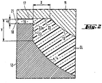
- FIG. 2 shows the arrangement of the mold 1 in the transition region between the mold cavity 15 and the annular channel 16 as an enlarged detail.
- the cavity 15 has here, by way of example, a shape that corresponds to the typical rim geometry of a so-called soft contact lens CL.
- the cavity rim, and thus the lens rim is formed here by two wall faces 22 and 23 which are arranged at right angles to one another and are arranged on the male and on the female mold halves 11 and 12 respectively.
- the width and the height of those two wall faces, and of the rim areas of the contact lens defined by them, are indicated by X and Y respectively.
- the lens rim may in practice also be slightly rounded.
- the cylindrical wall face 23 of the female mold half 12 does not extend right up to the fiat wall face 22 and the wall face 17, lying seamlessly adjacent thereto, of the male mold half 11, but is lower by the amount ⁇ y, so that the annular gap 16 already mentioned , between the wall face 17 and the wall face 18 of the two mold halves 11 and 12, is formed or remains open.
- the mask 21 provided on the wall face 17 of the male mold half 11 in this example embodiment extends horizontally exactly up to the extension 23a of the wall face. 23 of the female mold half 12.
- the UV light in the form of a parallel beam 3 causing the crosslinking, is incident at right angles to the wall face 22 and 17 and parallel to the cylindrical wall face 23, the space located at right angles below the mask 21 is in shadow and only the material located inside the cavity 15, that is inside the imaginary wall extension 23a, is crosslinked, resulting in a clean and burr-free lens rim which does not require any subsequent mechanical processing.
- parallel energy radiation is used, therefore, disregarding the diffraction and scattering effects, which are usually negligible in practice, the contour of the mask 21 is transferred two-dimensionally parallel and (in this case) downwards into the rim area of the contact lens. Therefore, if the two mold halves 11 and 12 are separated from one another by the annular gap 16 of height ⁇ y, the rim is formed towards the outside of the area resulting from that displacement by means of the spatial restriction of the energy radiation.
- the invention in one respect, is directed a reusable mold for making a contact lens, comprising a first mold half having a first mold surface in contact with a silicone containing lens forming composition and a second mold half having a second mold surface in contact with the lens forming composition, wherein the first mold half and the second mold half are configured to receive each other such that a cavity is formed between the first mold surface and the second mold surface, wherein the cavity defines the shape of a contact lens to be molded, wherein the lens forming composition is polymerizable and/or crosslinkable by an actinic radiation, wherein at least one of the mold halves is made from an oxide glass material having a UV transmission cut-off wavelength no less than 390 nm and a specific gravity higher than 3.5.
- Lightstream TechnologyTM (Alcon) involving reusable molds and curing a lens-forming composition under a spatial limitation of actinic radiation.
- the impingement upon the material of the energy causing crosslinking is restricted spatially to the region of the mold cavity, so that substantially only the starting material located in the mold cavity, that is to say the region of the contact lens, is crosslinked. Any excess starting material present is not polymerized or crosslinked.
- partial areas of the contact lens edge are formed not by a mechanical limitation of the material by mold walls but by a spatial restriction of the impinging energy (usually UV or some other radiation) that triggers the polymerization or crosslinking.
- the projected beam of radiation limits radiation (e.g., UV radiation) impinging on the pre-polymerization mixture of the lens-forming materials located in the path of the projected beam from the first molding surface to the second molding surface of the reusable mold.
- the resultant contact lens comprises an anterior surface defined by the first molding surface, an opposite posterior surface defined by the second molding surface, and a lens edge defined by the sectional profile of the projected radiation beam (i.e., a spatial limitation of radiation).
- Examples of reusable molds suitable for spatial limitation of radiation include without limitation those disclosed in U.S. Patent Nos. 6,627,124 , 6,800,225 , 7,384,590 , and 7,387,759 .
- the mold half facing away from the energy source it is in principle possible for the mold half facing away from the energy source to be produced from any material which withstands the crosslinkable material or components thereof.
- potential reflections and scattering of curing light are to be expected, depending on the type of energetic radiation (such as wavelength of curing light), and these may possibly lead to undesired effects such as producing flash on the edge because the reflections and scattering of curing light will polymerizing the lens forming material in the gap area between two molds.
- the invention is partly based on the discovery that a hydrogel contact lens can be made using Lightstream TechnologyTM with mold system having at least one of the mold halves is made from an oxide glass material having a UV transmission cut-off wavelength no less than 390 nm and a specific gravity higher than 3.5 enable to achieve a hydrogel contact lens having a clean lens edge without flash. It is believed that reduction of reflection and scattering of curing light by using a mold system having at least one of the mold halves is made from an oxide glass material which having a UV transmission cut-off wavelength no less than 390 nm and a specific gravity higher than 3.5.
- lens forming material left in the gap between base curve mold and front curve under a spatial limitation of actinic radiation will not be cured, and the un-crosslinked lens forming material left in the gap between base curve mold and front curve under a spatial limitation of actinic radiation can be washed away.
- a hydrogel contact lens having a clean lens edge without flash can be produced.
- any UV absorbing glass can be used as a mold material provided the UV absorbing glass has a UV cut -off wave length no less than 390 nm (defined as % transmission is no larger than 1%).
- Glasses absorb UV are caused by small defects in the composition such as Iron as well as intentional additions like Na 2 O. The reason for this UV absorption has to do with the bonding of each glass type.
- Most commercial glasses are sodium-silicates. These glasses consist of a connected silica network, which is broken up by the alkali (sodium). The addition of sodium breaks the network creating non-bridging oxygens, which lowers the melting temperature as well as reducing the energy of electromagnetic radiation needed for absorption. In combination with small amounts of iron impuriity, which leads to intense UV absorption bands, these non-bridging oxygens prevent the transmission of UV light.
- UV edges the frequency of UV light that begins being absorbed. In essence, the more loosely the electrons are bound, usually because they are not involved in covalent bonding in the case of non-bridging oxygens, the less UV light is transmitted.
- glasses formed with heavy metal (atomic weight >100) oxides comprising of an oxide formed from Tellurium (Te), Lead (Pb), Tantalum (Ta), Bismuth (Bi), Antimony (Sb), or combinations thereof are preferred UV absorbent glasses as long as they have high refractive index, high density and a UV light absorbing with cut-off wavelength no less than 390 nm.
- the heavy metal (atomic weight >100) oxides containing glasses show higher refractive index and higher UV transmission cut-off wavelength.
- the increase in refractive index and UV transmission cut-off wavelength are attributed to the generation of non bridging oxygen due to incorporation of heavy metal-O in the glass network.
- These glasses are also show high density with increase in heavy metal oxide content.
- UV absorbing glasses include: Sumita K-PSFn1, K-PSFn2, K-PSFn173, K-PSFn215, Schott P-SF67, P-SF68, Ohara L-BBH1, S-NPH 3, and Hoya E-FDS1 are identified. All UV absorbing glasses have index of refraction > 1.9 and denser with specific gravity SG > 3.5.
- the most preferred heavy metal (atomic weight >100) oxides glasses are Bismuth oxide glasses, for example, Ohara L-BBH1, Schott P-SF67, P-SF68, etc.
- the above commercially available UV absorbing glasses can be made into mold by precision press mold, if the glass having HK value below 350, then it can also be single point diamond turned (SPDT) or both depending on their glass transition temperature and Knoop Hardness (HK) hardness.
- SPDT single point diamond turned
- commercially available UV absorbing glasses having a glass transition temperature less than 600°C can be made into mold by precision press molding process, having a HK hardness less than 350 can be made into mold by SPDT process.
- Ohara L-BBH1 not only can be precision press molded to produce front curve molds in production, they also can be machined (single point diamond turned) to produce optically smotth surface in lens prototyping.
- UV absorbing glasses such as Ohara L-BBH1 have the potential of seamless transition from prototyping to production molds.
- Table 1 summarizes a list of UV absorbing glasses offered by Sumita, Schott, Ohara, and Hoya. Some common characteristics of these glasses are: Index of refraction is fairly large with nd > 1.9 in all cases.
- Tg and AT or press mold temperature are nominal.
- CTE values are in the order of 10-5/K with exception of P-SF67, S-NPH 3, and E-FDS1 glasses have lower CTE of ⁇ 7x10⁻⁶/K (100 to 300°C).
- L-BBH1 has the lowest HK of 330, while other grades have higher HK (Knoop hardness) values.
- Table 1 UV absorbing glass property comparisons. UV cut-off wavelength defined as %T ⁇ 1%. Nikon glass is not considered as UV absorbing glass.
- a lens-forming material refers to any material which can be polymerized and/or crosslinked by actinic radiation to form a contact lens.
- a preferred group of lens-forming materials are prepolymers which are water-soluble and/or meltable. It would be advantageous that a lens-forming material comprises primarily one or more prepolymers which are preferably in a substantially pure form (e.g., purified by ultrafiltration).
- prefunctionalised PVA (polyvinyl alcohol) polymer used as lens forming material, as illustrated in U.S. Patent Nos. 5,508,317 ; 8,030,369 and U.S. patent application publication no. 2006/0251696 .
- a more preferred group of lens -forming materials is silicone-containing hydrogel.
- silicone-containing hydrogel comprises at least one components selected from the group consisting of a silicone-containing vinylic monomer, a silicone-containing vinylic macromer, a silicone-containing prepolymer, a hydrophilic vinylic monomer, a hydrophobic vinylic monomer, a crosslinking agent, a free-radical initiator (photoinitiator or thermal initiator), a hydrophilic vinylic macromer/prepolymer, and combinations thereof, as well known to a person skilled in the art, as illustrated in U.S. Patent Nos. 5,760,100 and 8,480,227 .
- a still more preferred group of lens -forming materials is UV-absorbing silicone-containing hydrogel.
- UV-absorbing silicone-containing hydrogel lens forming mixture comprises at least one hydrophilic vinylic monomer, at least one siloxane-containing vinylic monomer, at least one polysiloxane crosslinker (with two or more ethylenically-unsaturated groups), at least one UV-absorbing vinylic monomer that absorbs ultraviolet light and optionally (but preferably) high-energy violet light from 381 nm to 440 nm, at least one tinting agent, and at least one germanium-based Norrish Type I photoinitiator capable of initiating a free-radical polymerization under irradiation with a light source including a light in the region of about 380 to about 550 nm, and the UV-absorbing silicone-containing hydrogel lens forming mixture is irradiated in the mold with a light in a region of from 380 to 550 nm and crosslinking the lens-forming materials to form the UV-absorbing silicone hydrogel contact lens, as illustrated in co-pending case, U.S.
- a UV-absorbing vinylic monomer used in the invention comprises a benzophenone-moiety, preferably a benzotriazole-moiety.
- a UV-absorbing vinylic monomer used in the invention is a benzotriazole-containing UV/HEVL absorber that absorbs both ultraviolet light and high-energy violet light (HEVL), for example, 2-(2'-hydroxy-5'-methacryloxyethylphenyl) benzotriazole (2-Propenoic acid, 2-methyl-, 2-[3-(2H-benzotriazol-2-yl)-4-hydroxyphenyl]ethyl ester, Norbloc).
- HUVL high-energy violet light
- germanium-based Norrish Type I photoinitiators can be used in the UV-absorbing silicone-containing hydrogel lens forming mixture, so long as they are capable of initiating a free-radical polymerization under irradiation with a light source including a light in the region of about 380 to about 550 nm.
- germanium-based Norrish Type I photoinitiators are acylgermanium compounds described in US 7,605,190 .
- light source can be any ones emitting light in the 380-550 nm range sufficient to activate germanium-based Norrish Type I photoinitiators.
- Blue-light sources are commercially available and include: the Palatray CU blue-light unit (available from Heraeus Kulzer, Inc., Irvine, Calif.), the Fusion F450 blue light system (available from TEAMCO, Richardson, Tex.), Dymax Blue Wave 200, LED light sources from Opsytec (385 nm, 395 nm, 405 nm, 435 nm, 445 nm, 460 nm), LED light sources from Hamamatsu (385 nm), and the GE 24" blue fluorescent lamp (available from General Electric Company, U.S.).
- a preferred blue-light source is the UV LED from Opsytec (those described above). The intensity of the light source is set to produce lenses of good quality given the light source and photoinitiator.
- the total intensity of the light source is preferably from about 10 to about 100 mW/cm2, preferably from about 20 to about 60 mW/cm2 in the 380 nm to 550 nm region is more preferred.
- the crosslinking may be effected in any time period of about 40 minutes or less, preferably in a very short time (e.g. in ⁇ about 120 seconds, preferably in ⁇ about 80 seconds, more preferably in ⁇ 50 about seconds, even more preferably in ⁇ about 30 seconds, and most preferably in 5 to 30 seconds).
- the invention in another respect, relates to a method for producing a contact lens, comprising: the steps of:
- IPDI isophorone diisocyanate
- the reactor is held for 4.5 h at about 40° C, forming HO-PDMS-IPDI-PDMS-IPDI-PDMS-OH.
- MEK is then removed under reduced pressure.
- the terminal hydroxyl-groups are capped with methacryloyloxyethyl groups in a third step by addition of 7.77 g of isocyanatoethylmethacrylate (IEM) and an additional 0.063 g of DBTDL, forming IEM-PDMS-IPDI-PDMS-IPDI-PDMS-IEM (i.e., CE-PDMS terminated with methacrylate groups).
- IEM isocyanatoethylmethacrylate
- 240.43 g of KF-6001 is added into a 1-L reactor equipped with stirring, thermometer, cryostat, dropping funnel, and nitrogen/vacuum inlet adapter, and then dried by application of high vacuum (2 ⁇ 10-2 mBar). Then, under an atmosphere of dry nitrogen, 320 g of distilled MEK is then added into the reactor and the mixture is stirred thoroughly. 0.235 g of DBTDL is added to the reactor. After the reactor is warmed to 45°C, 45.86 g of IPDI are added through an addition funnel over 10 minutes to the reactor under moderate stirring. The reaction is kept for 2 hours at 60°C.
- Lens formulations are prepared by mixing components listed in Table 2 below followed by heating at 40° C for 20 min.
- Table 2 Lens Formulation 2 Carbazole violet - CuP tint (%) 0.1 DMPC (%) 0.76 LPEG2000 (%) 0.61 Norbloc (%) 1 CE PDMS (%) Tris acrylamide (%) 19.71 Darocur 1173 (%) - Ge-PI (%) 0.36 1-propanol (%) 23.82 DMA (%) 23.24
- PAA-coating solution A polyacrylic acid (PAA) coating solution is prepared by dissolving an amount of PAA (M.W.: 450kDa, from Lubrizol) in a given volume of 1-propanol (1-PrOH) to have a concentration of about 0.44% by weight and the pH is adjusted with formic acid to about 2.0.
- PAA polyacrylic acid
- IPC saline In-Package-Coating solution
- Poly(AAm-co-AA)(90/10) partial sodium salt ( ⁇ 90% solid content, poly(AAm-co-AA) 90/10, Mw 200,000) is purchased from Polysciences, Inc. and used as received.
- Polyamidonamine epichlorohydrin (PAE) (Kymene, an azetidinium content of 0.46 assayed with NMR) is purchased from Ashland as an aqueous solution and used as received.
- IPC saline is prepared by dissolving about 0.07% w/w of poly(AAm-co-AA)(90/10) and about 0.15% of PAE (an initial azetidinium millimolar equivalents of about 8.8 millimole) in phosphate-buffered saline (PBS) (about 0.044 w/w% NaH2PO4 ⁇ H2O, about 0.388 w/w/% Na2HPO4 ⁇ 2H2O, about 0.79 w/w% NaCl) and adjusting the pH to 7.2 ⁇ 7.4. Then the IPC saline is heat pre-treated for about 4 hours at about 70° C (heat pretreatment).
- PBS phosphate-buffered saline
- poly(AAm-co-AA) and PAE are partially crosslinked to each other (i.e., not consuming all azetidinium groups of PAE) to form a water-soluble and thermally-crosslinkable hydrophilic polymeric material containing azetidinium groups within the branched polymer network in the IPC saline.
- the IPC is cooled to room temperature then filtered using a 0.22micron PES membrane filter.
- Lenses are prepared by cast-molding from the lens formulation prepared above in two set of reusable mold.
- the first set for lens sample 2A uses quartz base curve mold half and glass front curve mold half and the second set for lens sample 2B uses quartz base curve mold half and LBHH-1 front curve mold half.
- Lens formulation 2 prepared in Example 2 are used for both lens samples 2A and 2B.
- Lens formulation 2 in molds is irradiated for 25 seconds using a 405 nm LED supplied by Opsytec for both lens samples 2A and 2B.
- the measured total intensity from 350 to 460 nm is about 25 mW/cm2.
- Cast-molded contact lenses are then extracted by dipping in the following series of baths: deionized (DI) water bath (about 56 seconds); 3 methyl ethyl ketone (MEK) baths (about 22, 78, 224 seconds respectively, (DI) water bath (about 56 seconds).
- DI deionized
- MEK 3 methyl ethyl ketone
- DI water bath
- lens edge quality and curing conditions are given in Table 3 below.
- Table 3 2A 2B Cure Lamp 405nm LED 405nm LED Total Intensity (mW/cm2) 25 25 Cure Time(s) 25 25 Base Curve /Front Curve Mold quartz /N-B270 glass quartz /L-BBH1 Lens Edge Quality Heavy flash, bad lens edge quality No flash, great lens edge quality
Claims (14)
- Moule réutilisable (1) pour fabriquer une lentille de contact, comprenant une première moitié (11) de moule possédant une première surface (13) de moule en contact avec une composition de formation de lentille contenant de la silicone et une seconde moitié (12) de moule possédant une seconde surface (14) de moule en contact avec la composition de formation de lentille, dans lequel la première moitié (11) de moule et la seconde moitié (12) de moule sont conçues pour s'accueillir l'une l'autre de sorte qu'une cavité (15) soit formée entre la première surface (13) de moule et la seconde surface (14) de moule, dans lequel la cavité (15) définit la forme d'une lentille à mouler, dans lequel la composition de formation de lentille est polymérisable et/ou réticulable par un rayonnement actinique, caractérisé en ce qu'au moins une des moitiés (11, 12) de moule est faite d'un matériau à base de verre à oxyde possédant une longueur d'onde de coupure de transmission UV supérieure pas inférieure à 390 nm
et un poids spécifique supérieur à 3,5. - Moule réutilisable (1) pour fabriquer une lentille de contact selon la revendication 1, dans lequel le matériau à base de verre à oxyde comprend un oxyde de métal lourd formé à partir de tellure (Te), plomb (Pb), tantale (Ta), bismuth (Bi), antimoine (Sb) et des combinaisons de ceux-ci.
- Moule réutilisable (1) pour fabriquer une lentille de contact selon l'une quelconque des revendications précédentes, dans lequel le matériau à base de verre à oxyde possède une température de transition vitreuse inférieure à 600 °C.
- Moule réutilisable (1) pour fabriquer une lentille de contact selon l'une quelconque des revendications précédentes, dans lequel le matériau à base de verre à oxyde possède un indice de réfraction supérieur à 1,9.
- Moule réutilisable (1) pour fabriquer une lentille de contact selon l'une quelconque des revendications précédentes, dans lequel le matériau à base de verre à oxyde possède une longueur d'onde de coupure de transmission UV pas inférieure à 410 nm.
- Moule réutilisable (1) pour fabriquer une lentille de contact selon l'une quelconque des revendications précédentes, dans lequel le matériau à base de verre à oxyde a un poids spécifique supérieur à 4,5.
- Moule réutilisable (1) pour fabriquer une lentille de contact selon l'une quelconque des revendications précédentes, le moule réutilisable étant fabriqué par un procédé presse de précision.
- Moule réutilisable (1) pour fabriquer une lentille de contact selon l'une quelconque des revendications précédentes, le moule réutilisable étant fabriqué par un tournage à pointe de diamant unique.
- Procédé de production d'une lentille de contact, comportant les étapes consistant à :(1) fournir un moule (1) de lentille de contact, le moule (1) comprenant une première moitié (11) de moule possédant une première surface (13) de moule et une seconde moitié (12) de moule possédant une seconde surface (14) de moule, dans lequel la première moitié (11) de moule et la seconde moitié (12) de moule sont conçues pour s'accueillir l'une l'autre de sorte qu'une cavité (15) soit formée entre la première surface (13) de moule et la seconde surface (14) de moule, dans lequel la cavité (15) définit la forme d'une lentille de contact à mouler, caractérisé en ce qu'au moins une des moitiés (11, 12) de moule est faite d'un matériau à base de verre à oxyde possédant une longueur d'onde de coupure de transmission UV pas inférieure à 390 nm et un poids spécifique supérieur à 3,5,(2) introduire une composition de formation de lentille dans la cavité (15) formée par les première et seconde surfaces de moulage (13, 14), le matériau de formation de lentille étant réticulable et/ou polymérisable par rayonnement actinique ;(3) réticuler/polymériser le matériau de formation de lentille dans le moule pour former une lentille possédant une matrice polymère ;(4) ouvrir le moule (1) et retirer la lentille de contact formée du moule (1), la lentille de contact formée possédant un bord de lentille de contact propre sans bavure.
- Procédé de production d'une lentille de contact selon la revendication 9, dans lequel le matériau à base de verre à oxyde comprend un oxyde de métal lourd formé à partir de tellure (Te), plomb (Pb), tantale (Ta), bismuth (Bi), antimoine (Sb) et des combinaisons de ceux-ci.
- Procédé de production d'une lentille de contact selon l'une quelconque des revendications 9 à 10, dans lequel le matériau à base de verre à oxyde possède un indice de réfraction supérieur à 1,9.
- Procédé de production d'une lentille de contact selon l'une quelconque des revendications 9 à 11, dans lequel le matériau à base de verre à oxyde possède une longueur d'onde de coupure de transmission UV pas inférieure à 410 nm.
- Procédé de production d'une lentille de contact selon l'une quelconque des revendications 9 à 12, dans lequel le moule réutilisable (1) est fabriqué par un procédé presse de précision.
- Procédé de production d'une lentille de contact selon l'une quelconque des revendications 9 à 13, dans lequel le moule réutilisable (1) est fabriqué par un tournage à pointe de diamant unique.
Applications Claiming Priority (2)
| Application Number | Priority Date | Filing Date | Title |
|---|---|---|---|
| US201462092907P | 2014-12-17 | 2014-12-17 | |
| PCT/US2015/066008 WO2016100457A1 (fr) | 2014-12-17 | 2015-12-16 | Moules de lentille réutilisables et procédés d'utilisation associés |
Publications (2)
| Publication Number | Publication Date |
|---|---|
| EP3233449A1 EP3233449A1 (fr) | 2017-10-25 |
| EP3233449B1 true EP3233449B1 (fr) | 2019-07-24 |
Family
ID=55077646
Family Applications (1)
| Application Number | Title | Priority Date | Filing Date |
|---|---|---|---|
| EP15821215.9A Active EP3233449B1 (fr) | 2014-12-17 | 2015-12-16 | Moules de lentille réutilisables et procédés d'utilisation associés |
Country Status (3)
| Country | Link |
|---|---|
| US (1) | US9981436B2 (fr) |
| EP (1) | EP3233449B1 (fr) |
| WO (1) | WO2016100457A1 (fr) |
Families Citing this family (14)
| Publication number | Priority date | Publication date | Assignee | Title |
|---|---|---|---|---|
| US8697770B2 (en) | 2010-04-13 | 2014-04-15 | Johnson & Johnson Vision Care, Inc. | Pupil-only photochromic contact lenses displaying desirable optics and comfort |
| US8877103B2 (en) | 2010-04-13 | 2014-11-04 | Johnson & Johnson Vision Care, Inc. | Process for manufacture of a thermochromic contact lens material |
| US11021558B2 (en) | 2016-08-05 | 2021-06-01 | Johnson & Johnson Vision Care, Inc. | Polymer compositions containing grafted polymeric networks and processes for their preparation and use |
| US11034789B2 (en) | 2018-01-30 | 2021-06-15 | Johnson & Johnson Vision Care, Inc. | Ophthalmic devices containing localized grafted networks and processes for their preparation and use |
| US10961341B2 (en) | 2018-01-30 | 2021-03-30 | Johnson & Johnson Vision Care, Inc. | Ophthalmic devices derived from grafted polymeric networks and processes for their preparation and use |
| US10935695B2 (en) | 2018-03-02 | 2021-03-02 | Johnson & Johnson Vision Care, Inc. | Polymerizable absorbers of UV and high energy visible light |
| US11724471B2 (en) * | 2019-03-28 | 2023-08-15 | Johnson & Johnson Vision Care, Inc. | Methods for the manufacture of photoabsorbing contact lenses and photoabsorbing contact lenses produced thereby |
| US11958824B2 (en) | 2019-06-28 | 2024-04-16 | Johnson & Johnson Vision Care, Inc. | Photostable mimics of macular pigment |
| US11543683B2 (en) | 2019-08-30 | 2023-01-03 | Johnson & Johnson Vision Care, Inc. | Multifocal contact lens displaying improved vision attributes |
| US11912800B2 (en) | 2021-09-29 | 2024-02-27 | Johnson & Johnson Vision Care, Inc. | Amide-functionalized polymerization initiators and their use in the manufacture of ophthalmic lenses |
| US11971518B2 (en) | 2022-04-28 | 2024-04-30 | Johnson & Johnson Vision Care, Inc. | Shape engineering of particles to create a narrow spectral filter against a specific portion of the light spectrum |
| US20230348718A1 (en) | 2022-04-28 | 2023-11-02 | Johnson & Johnson Vision Care, Inc. | Light-filtering materials for biomaterial integration and methods thereof |
| US20230350230A1 (en) | 2022-04-28 | 2023-11-02 | Johnson & Johnson Vision Care, Inc. | Using particles for light filtering |
| US11733440B1 (en) | 2022-04-28 | 2023-08-22 | Johnson & Johnson Vision Care, Inc. | Thermally stable nanoparticles and methods thereof |
Family Cites Families (29)
| Publication number | Priority date | Publication date | Assignee | Title |
|---|---|---|---|---|
| US3723141A (en) * | 1971-03-22 | 1973-03-27 | W Dumbaugh | Infrared transmissive lead bismuthate glasses |
| JPS61106211A (ja) | 1984-10-30 | 1986-05-24 | Hoya Corp | 親水性プラスチックレンズ製造用鋳型 |
| US4701425A (en) | 1986-05-19 | 1987-10-20 | Libbey-Owens-Ford Co. | Infrared and ultraviolet absorbing glass compositions |
| US5071460A (en) | 1988-03-04 | 1991-12-10 | Nippon Telegraph And Telephone Corporation | Process for the preparation of fluoride glass and process for the preparation of optical fiber preform using the fluoride glass |
| US4898777A (en) | 1989-01-24 | 1990-02-06 | Infrared Fiber Systems | High-strength fluoride glass fibers and process of making |
| JPH0662318B2 (ja) | 1990-05-23 | 1994-08-17 | セントラル硝子株式会社 | フッ化物ガラスの表面処理法 |
| US5817160A (en) | 1992-12-16 | 1998-10-06 | The Center For Innovative Technology | UV absorbing glass |
| US6800225B1 (en) | 1994-07-14 | 2004-10-05 | Novartis Ag | Process and device for the manufacture of mouldings and mouldings manufactured in accordance with that process |
| TW272976B (fr) | 1993-08-06 | 1996-03-21 | Ciba Geigy Ag | |
| US5760100B1 (en) | 1994-09-06 | 2000-11-14 | Ciba Vision Corp | Extended wear ophthalmic lens |
| US5629246A (en) | 1995-09-27 | 1997-05-13 | Micron Technology, Inc. | Method for forming fluorine-doped glass having low concentrations of free fluorine |
| EP0835848A3 (fr) | 1996-08-21 | 1998-06-10 | Nikon Corporation | Verre de silice contenant du fluor, son procédé de fabrication et un appareil d'exposition par projection contenant ce verre |
| TW429327B (en) | 1997-10-21 | 2001-04-11 | Novartis Ag | Single mould alignment |
| US6037286A (en) | 1998-03-20 | 2000-03-14 | Owens-Brockway Glass Container Inc. | UV absorbing container glass compositions |
| US6838400B1 (en) | 1998-03-23 | 2005-01-04 | International Business Machines Corporation | UV absorbing glass cloth and use thereof |
| JP2000326347A (ja) | 1999-05-21 | 2000-11-28 | Menicon Co Ltd | 眼用レンズの成形型及びそれを用いた眼用レンズの製造方法 |
| AU2001247253A1 (en) | 2000-03-31 | 2001-10-15 | Bausch And Lomb Incorporated | Method and mold to control optical device polymerization |
| JP2002114531A (ja) | 2000-08-04 | 2002-04-16 | Sumitomo Electric Ind Ltd | フッ素添加ガラス |
| US7387759B2 (en) | 2002-12-17 | 2008-06-17 | Novartis Ag | System and method for curing polymeric moldings having a masking collar |
| US7384590B2 (en) | 2002-12-17 | 2008-06-10 | Novartis Ag | System and method for curing polymeric moldings |
| DE102004027120B4 (de) | 2003-06-06 | 2013-01-31 | Schott Ag | Verwendung eines UV-Strahlung absorbierenden Neutralglases, insbesondere für Fluoreszenzlampen |
| US8030369B2 (en) | 2004-10-13 | 2011-10-04 | Novartis Ag | Contact lenses with improved wearing comfort |
| US9804295B2 (en) | 2005-05-05 | 2017-10-31 | Novartis Ag | Ophthalmic devices for sustained delivery of active compounds |
| EP1905415B1 (fr) | 2006-09-27 | 2009-07-01 | Ivoclar Vivadent AG | Compositions polymérisable avec acyl-germanium comme amorceurs |
| CN102257408B (zh) | 2008-12-18 | 2014-07-09 | 诺华股份有限公司 | 制造硅酮水凝胶接触透镜的方法 |
| KR101889246B1 (ko) | 2010-07-30 | 2018-08-16 | 노파르티스 아게 | 수분이 풍부한 표면을 갖는 실리콘 히드로겔 렌즈 |
| US9315669B2 (en) | 2013-09-30 | 2016-04-19 | Novartis Ag | Method for making UV-absorbing ophthalmic lenses |
| CN105829082B (zh) | 2013-12-20 | 2019-06-07 | 诺华股份有限公司 | 可再使用的铸造模具及制备此类模具的方法 |
| SG11201603720YA (en) | 2013-12-20 | 2016-07-28 | Novartis Ag | Molds for making contact lenses |
-
2015
- 2015-12-16 WO PCT/US2015/066008 patent/WO2016100457A1/fr active Application Filing
- 2015-12-16 EP EP15821215.9A patent/EP3233449B1/fr active Active
- 2015-12-16 US US14/970,827 patent/US9981436B2/en active Active
Non-Patent Citations (1)
| Title |
|---|
| None * |
Also Published As
| Publication number | Publication date |
|---|---|
| EP3233449A1 (fr) | 2017-10-25 |
| US20160176134A1 (en) | 2016-06-23 |
| US9981436B2 (en) | 2018-05-29 |
| WO2016100457A1 (fr) | 2016-06-23 |
Similar Documents
| Publication | Publication Date | Title |
|---|---|---|
| EP3233449B1 (fr) | Moules de lentille réutilisables et procédés d'utilisation associés | |
| US10324311B2 (en) | Visible-light photoinitiators and uses thereof | |
| US10472319B2 (en) | Water-soluble UV-absorbing compounds and uses thereof | |
| US10823983B2 (en) | UV-absorbing vinylic monomers and uses thereof | |
| EP3083217B1 (fr) | Moules utilisables en vue de la fabrication de lentilles de contact | |
| EP3390025B1 (fr) | Moules de lentille réutilisables et ses procédés d'utilisation | |
| EP3233450B1 (fr) | Moules réutilisables pour lentilles et leurs procédés d'utilisation | |
| EP2637847B1 (fr) | Procédé pour fabriquer des lentilles de contact | |
| KR20210009257A (ko) | 청색광 차단용 콘택트렌즈 및 이의 제조방법 | |
| EP3233448B1 (fr) | Procédés d'utilisation des moules réutilisables pour lentilles | |
| EP3173826B1 (fr) | Composition d'hydrogel et lentilles de contact à hydrogel constituées de la composition | |
| KR102400436B1 (ko) | 근적외선 차단 및 청색광 차단 기능을 갖는 다기능 편광렌즈의 제조방법 및 이에 의해 제조된 다기능 편광렌즈 | |
| KR102184978B1 (ko) | 콘택트렌즈 제조방법 | |
| CN1224172A (zh) | 超微粒近视镜片 |
Legal Events
| Date | Code | Title | Description |
|---|---|---|---|
| STAA | Information on the status of an ep patent application or granted ep patent |
Free format text: STATUS: THE INTERNATIONAL PUBLICATION HAS BEEN MADE |
|
| PUAI | Public reference made under article 153(3) epc to a published international application that has entered the european phase |
Free format text: ORIGINAL CODE: 0009012 |
|
| STAA | Information on the status of an ep patent application or granted ep patent |
Free format text: STATUS: REQUEST FOR EXAMINATION WAS MADE |
|
| 17P | Request for examination filed |
Effective date: 20170704 |
|
| AK | Designated contracting states |
Kind code of ref document: A1 Designated state(s): AL AT BE BG CH CY CZ DE DK EE ES FI FR GB GR HR HU IE IS IT LI LT LU LV MC MK MT NL NO PL PT RO RS SE SI SK SM TR |
|
| AX | Request for extension of the european patent |
Extension state: BA ME |
|
| DAV | Request for validation of the european patent (deleted) | ||
| DAX | Request for extension of the european patent (deleted) | ||
| GRAP | Despatch of communication of intention to grant a patent |
Free format text: ORIGINAL CODE: EPIDOSNIGR1 |
|
| STAA | Information on the status of an ep patent application or granted ep patent |
Free format text: STATUS: GRANT OF PATENT IS INTENDED |
|
| RIC1 | Information provided on ipc code assigned before grant |
Ipc: B29C 33/38 20060101ALI20190128BHEP Ipc: B29D 11/00 20060101AFI20190128BHEP |
|
| INTG | Intention to grant announced |
Effective date: 20190214 |
|
| GRAS | Grant fee paid |
Free format text: ORIGINAL CODE: EPIDOSNIGR3 |
|
| GRAA | (expected) grant |
Free format text: ORIGINAL CODE: 0009210 |
|
| STAA | Information on the status of an ep patent application or granted ep patent |
Free format text: STATUS: THE PATENT HAS BEEN GRANTED |
|
| AK | Designated contracting states |
Kind code of ref document: B1 Designated state(s): AL AT BE BG CH CY CZ DE DK EE ES FI FR GB GR HR HU IE IS IT LI LT LU LV MC MK MT NL NO PL PT RO RS SE SI SK SM TR |
|
| REG | Reference to a national code |
Ref country code: GB Ref legal event code: FG4D |
|
| REG | Reference to a national code |
Ref country code: CH Ref legal event code: EP |
|
| REG | Reference to a national code |
Ref country code: DE Ref legal event code: R096 Ref document number: 602015034481 Country of ref document: DE |
|
| REG | Reference to a national code |
Ref country code: AT Ref legal event code: REF Ref document number: 1157681 Country of ref document: AT Kind code of ref document: T Effective date: 20190815 |
|
| REG | Reference to a national code |
Ref country code: IE Ref legal event code: FG4D |
|
| REG | Reference to a national code |
Ref country code: NL Ref legal event code: MP Effective date: 20190724 |
|
| REG | Reference to a national code |
Ref country code: LT Ref legal event code: MG4D |
|
| REG | Reference to a national code |
Ref country code: AT Ref legal event code: MK05 Ref document number: 1157681 Country of ref document: AT Kind code of ref document: T Effective date: 20190724 |
|
| PG25 | Lapsed in a contracting state [announced via postgrant information from national office to epo] |
Ref country code: NO Free format text: LAPSE BECAUSE OF FAILURE TO SUBMIT A TRANSLATION OF THE DESCRIPTION OR TO PAY THE FEE WITHIN THE PRESCRIBED TIME-LIMIT Effective date: 20191024 Ref country code: FI Free format text: LAPSE BECAUSE OF FAILURE TO SUBMIT A TRANSLATION OF THE DESCRIPTION OR TO PAY THE FEE WITHIN THE PRESCRIBED TIME-LIMIT Effective date: 20190724 Ref country code: AT Free format text: LAPSE BECAUSE OF FAILURE TO SUBMIT A TRANSLATION OF THE DESCRIPTION OR TO PAY THE FEE WITHIN THE PRESCRIBED TIME-LIMIT Effective date: 20190724 Ref country code: LT Free format text: LAPSE BECAUSE OF FAILURE TO SUBMIT A TRANSLATION OF THE DESCRIPTION OR TO PAY THE FEE WITHIN THE PRESCRIBED TIME-LIMIT Effective date: 20190724 Ref country code: HR Free format text: LAPSE BECAUSE OF FAILURE TO SUBMIT A TRANSLATION OF THE DESCRIPTION OR TO PAY THE FEE WITHIN THE PRESCRIBED TIME-LIMIT Effective date: 20190724 Ref country code: NL Free format text: LAPSE BECAUSE OF FAILURE TO SUBMIT A TRANSLATION OF THE DESCRIPTION OR TO PAY THE FEE WITHIN THE PRESCRIBED TIME-LIMIT Effective date: 20190724 Ref country code: BG Free format text: LAPSE BECAUSE OF FAILURE TO SUBMIT A TRANSLATION OF THE DESCRIPTION OR TO PAY THE FEE WITHIN THE PRESCRIBED TIME-LIMIT Effective date: 20191024 Ref country code: PT Free format text: LAPSE BECAUSE OF FAILURE TO SUBMIT A TRANSLATION OF THE DESCRIPTION OR TO PAY THE FEE WITHIN THE PRESCRIBED TIME-LIMIT Effective date: 20191125 Ref country code: SE Free format text: LAPSE BECAUSE OF FAILURE TO SUBMIT A TRANSLATION OF THE DESCRIPTION OR TO PAY THE FEE WITHIN THE PRESCRIBED TIME-LIMIT Effective date: 20190724 |
|
| PG25 | Lapsed in a contracting state [announced via postgrant information from national office to epo] |
Ref country code: GR Free format text: LAPSE BECAUSE OF FAILURE TO SUBMIT A TRANSLATION OF THE DESCRIPTION OR TO PAY THE FEE WITHIN THE PRESCRIBED TIME-LIMIT Effective date: 20191025 Ref country code: LV Free format text: LAPSE BECAUSE OF FAILURE TO SUBMIT A TRANSLATION OF THE DESCRIPTION OR TO PAY THE FEE WITHIN THE PRESCRIBED TIME-LIMIT Effective date: 20190724 Ref country code: AL Free format text: LAPSE BECAUSE OF FAILURE TO SUBMIT A TRANSLATION OF THE DESCRIPTION OR TO PAY THE FEE WITHIN THE PRESCRIBED TIME-LIMIT Effective date: 20190724 Ref country code: IS Free format text: LAPSE BECAUSE OF FAILURE TO SUBMIT A TRANSLATION OF THE DESCRIPTION OR TO PAY THE FEE WITHIN THE PRESCRIBED TIME-LIMIT Effective date: 20191124 Ref country code: RS Free format text: LAPSE BECAUSE OF FAILURE TO SUBMIT A TRANSLATION OF THE DESCRIPTION OR TO PAY THE FEE WITHIN THE PRESCRIBED TIME-LIMIT Effective date: 20190724 Ref country code: ES Free format text: LAPSE BECAUSE OF FAILURE TO SUBMIT A TRANSLATION OF THE DESCRIPTION OR TO PAY THE FEE WITHIN THE PRESCRIBED TIME-LIMIT Effective date: 20190724 |
|
| PG25 | Lapsed in a contracting state [announced via postgrant information from national office to epo] |
Ref country code: TR Free format text: LAPSE BECAUSE OF FAILURE TO SUBMIT A TRANSLATION OF THE DESCRIPTION OR TO PAY THE FEE WITHIN THE PRESCRIBED TIME-LIMIT Effective date: 20190724 |
|
| PG25 | Lapsed in a contracting state [announced via postgrant information from national office to epo] |
Ref country code: IT Free format text: LAPSE BECAUSE OF FAILURE TO SUBMIT A TRANSLATION OF THE DESCRIPTION OR TO PAY THE FEE WITHIN THE PRESCRIBED TIME-LIMIT Effective date: 20190724 Ref country code: RO Free format text: LAPSE BECAUSE OF FAILURE TO SUBMIT A TRANSLATION OF THE DESCRIPTION OR TO PAY THE FEE WITHIN THE PRESCRIBED TIME-LIMIT Effective date: 20190724 Ref country code: PL Free format text: LAPSE BECAUSE OF FAILURE TO SUBMIT A TRANSLATION OF THE DESCRIPTION OR TO PAY THE FEE WITHIN THE PRESCRIBED TIME-LIMIT Effective date: 20190724 Ref country code: DK Free format text: LAPSE BECAUSE OF FAILURE TO SUBMIT A TRANSLATION OF THE DESCRIPTION OR TO PAY THE FEE WITHIN THE PRESCRIBED TIME-LIMIT Effective date: 20190724 Ref country code: EE Free format text: LAPSE BECAUSE OF FAILURE TO SUBMIT A TRANSLATION OF THE DESCRIPTION OR TO PAY THE FEE WITHIN THE PRESCRIBED TIME-LIMIT Effective date: 20190724 |
|
| PG25 | Lapsed in a contracting state [announced via postgrant information from national office to epo] |
Ref country code: CZ Free format text: LAPSE BECAUSE OF FAILURE TO SUBMIT A TRANSLATION OF THE DESCRIPTION OR TO PAY THE FEE WITHIN THE PRESCRIBED TIME-LIMIT Effective date: 20190724 Ref country code: SM Free format text: LAPSE BECAUSE OF FAILURE TO SUBMIT A TRANSLATION OF THE DESCRIPTION OR TO PAY THE FEE WITHIN THE PRESCRIBED TIME-LIMIT Effective date: 20190724 Ref country code: SK Free format text: LAPSE BECAUSE OF FAILURE TO SUBMIT A TRANSLATION OF THE DESCRIPTION OR TO PAY THE FEE WITHIN THE PRESCRIBED TIME-LIMIT Effective date: 20190724 Ref country code: IS Free format text: LAPSE BECAUSE OF FAILURE TO SUBMIT A TRANSLATION OF THE DESCRIPTION OR TO PAY THE FEE WITHIN THE PRESCRIBED TIME-LIMIT Effective date: 20200224 |
|
| REG | Reference to a national code |
Ref country code: DE Ref legal event code: R097 Ref document number: 602015034481 Country of ref document: DE |
|
| PLBE | No opposition filed within time limit |
Free format text: ORIGINAL CODE: 0009261 |
|
| STAA | Information on the status of an ep patent application or granted ep patent |
Free format text: STATUS: NO OPPOSITION FILED WITHIN TIME LIMIT |
|
| PG2D | Information on lapse in contracting state deleted |
Ref country code: IS |
|
| REG | Reference to a national code |
Ref country code: CH Ref legal event code: PL |
|
| 26N | No opposition filed |
Effective date: 20200603 |
|
| REG | Reference to a national code |
Ref country code: BE Ref legal event code: MM Effective date: 20191231 |
|
| PG25 | Lapsed in a contracting state [announced via postgrant information from national office to epo] |
Ref country code: SI Free format text: LAPSE BECAUSE OF FAILURE TO SUBMIT A TRANSLATION OF THE DESCRIPTION OR TO PAY THE FEE WITHIN THE PRESCRIBED TIME-LIMIT Effective date: 20190724 Ref country code: MC Free format text: LAPSE BECAUSE OF FAILURE TO SUBMIT A TRANSLATION OF THE DESCRIPTION OR TO PAY THE FEE WITHIN THE PRESCRIBED TIME-LIMIT Effective date: 20190724 |
|
| GBPC | Gb: european patent ceased through non-payment of renewal fee |
Effective date: 20191216 |
|
| PG25 | Lapsed in a contracting state [announced via postgrant information from national office to epo] |
Ref country code: LU Free format text: LAPSE BECAUSE OF NON-PAYMENT OF DUE FEES Effective date: 20191216 Ref country code: GB Free format text: LAPSE BECAUSE OF NON-PAYMENT OF DUE FEES Effective date: 20191216 Ref country code: FR Free format text: LAPSE BECAUSE OF NON-PAYMENT OF DUE FEES Effective date: 20191231 Ref country code: IE Free format text: LAPSE BECAUSE OF NON-PAYMENT OF DUE FEES Effective date: 20191216 |
|
| REG | Reference to a national code |
Ref country code: DE Ref legal event code: R081 Ref document number: 602015034481 Country of ref document: DE Owner name: ALCON INC., CH Free format text: FORMER OWNER: NOVARTIS AG, BASEL, CH |
|
| PG25 | Lapsed in a contracting state [announced via postgrant information from national office to epo] |
Ref country code: CH Free format text: LAPSE BECAUSE OF NON-PAYMENT OF DUE FEES Effective date: 20191231 Ref country code: LI Free format text: LAPSE BECAUSE OF NON-PAYMENT OF DUE FEES Effective date: 20191231 Ref country code: BE Free format text: LAPSE BECAUSE OF NON-PAYMENT OF DUE FEES Effective date: 20191231 |
|
| PG25 | Lapsed in a contracting state [announced via postgrant information from national office to epo] |
Ref country code: CY Free format text: LAPSE BECAUSE OF FAILURE TO SUBMIT A TRANSLATION OF THE DESCRIPTION OR TO PAY THE FEE WITHIN THE PRESCRIBED TIME-LIMIT Effective date: 20190724 |
|
| PG25 | Lapsed in a contracting state [announced via postgrant information from national office to epo] |
Ref country code: HU Free format text: LAPSE BECAUSE OF FAILURE TO SUBMIT A TRANSLATION OF THE DESCRIPTION OR TO PAY THE FEE WITHIN THE PRESCRIBED TIME-LIMIT; INVALID AB INITIO Effective date: 20151216 Ref country code: MT Free format text: LAPSE BECAUSE OF FAILURE TO SUBMIT A TRANSLATION OF THE DESCRIPTION OR TO PAY THE FEE WITHIN THE PRESCRIBED TIME-LIMIT Effective date: 20190724 |
|
| PG25 | Lapsed in a contracting state [announced via postgrant information from national office to epo] |
Ref country code: MK Free format text: LAPSE BECAUSE OF FAILURE TO SUBMIT A TRANSLATION OF THE DESCRIPTION OR TO PAY THE FEE WITHIN THE PRESCRIBED TIME-LIMIT Effective date: 20190724 |
|
| P01 | Opt-out of the competence of the unified patent court (upc) registered |
Effective date: 20230504 |
|
| PGFP | Annual fee paid to national office [announced via postgrant information from national office to epo] |
Ref country code: DE Payment date: 20231121 Year of fee payment: 9 |