EP3232188A1 - Coulometrischer feuchtesensor mit gelförmigem elektrolyt und herstellungsverfahren für einen coulometrischen feuchtesensor mit gelförmigem elektrolyt - Google Patents
Coulometrischer feuchtesensor mit gelförmigem elektrolyt und herstellungsverfahren für einen coulometrischen feuchtesensor mit gelförmigem elektrolyt Download PDFInfo
- Publication number
- EP3232188A1 EP3232188A1 EP17166618.3A EP17166618A EP3232188A1 EP 3232188 A1 EP3232188 A1 EP 3232188A1 EP 17166618 A EP17166618 A EP 17166618A EP 3232188 A1 EP3232188 A1 EP 3232188A1
- Authority
- EP
- European Patent Office
- Prior art keywords
- hygroscopic material
- electrodes
- substrate
- humidity sensor
- humidity
- Prior art date
- Legal status (The legal status is an assumption and is not a legal conclusion. Google has not performed a legal analysis and makes no representation as to the accuracy of the status listed.)
- Granted
Links
Images




Classifications
-
- G—PHYSICS
- G01—MEASURING; TESTING
- G01N—INVESTIGATING OR ANALYSING MATERIALS BY DETERMINING THEIR CHEMICAL OR PHYSICAL PROPERTIES
- G01N27/00—Investigating or analysing materials by the use of electric, electrochemical, or magnetic means
- G01N27/26—Investigating or analysing materials by the use of electric, electrochemical, or magnetic means by investigating electrochemical variables; by using electrolysis or electrophoresis
- G01N27/416—Systems
- G01N27/42—Measuring deposition or liberation of materials from an electrolyte; Coulometry, i.e. measuring coulomb-equivalent of material in an electrolyte
- G01N27/423—Coulometry
Definitions
- the invention relates to a coulometric humidity sensor and to a production method for a coulometric humidity sensor.
- the moisture in gases is an important analytical parameter in the process industry, including gas manufacturers, gas suppliers and the semiconductor industry. Even small amounts of moisture can adversely affect, for example, manufacturing processes in the semiconductor industry. In addition, moisture is of great interest in extraterrestrial research, particularly in planetary research. Therefore, there is a great need to accurately determine the trace moisture in gases.
- the coulometric method is used.
- water molecules are absorbed on a self-substantially non-conductive hygroscopic material.
- a voltage is applied via two separate electrodes arranged in contact with the hygroscopic material. This triggers electrolytic dissociation of the water molecules into hydrogen and oxygen. Due to the dissociation and the released 2 electrons per dissociated molecule, a current flow is proportional to the number of dissociated molecules.
- a current measurement measures the number of charge carriers generated during dissociation. The measured current is thus proportional to the number of absorbed and dissociated molecules.
- the coulometric measurement principle was developed by Keidel and is described in the article " Determination of Water by Direct Amperometric Measurement "in Journal Anal Chem 31 (1959), pp. 2043-2048 described.
- the measuring system described there consists of a sensor which is located in a measuring cell, a mass flow controller, a DC voltage source and an ammeter.
- the mass flow controller directs a defined volume flow over the sensor.
- the sensor consists of a Substrate, eg glass or ceramic, on which there are two electrodes, generally of platinum. Between the electrodes and in contact therewith is arranged a hygroscopic material which is preferably phosphorus pentoxide (P 2 O 5 ). This absorbs water.
- the absorbed water is electrolyzed and there is a current proportional to the absorbed water.
- a measuring system is often operated in bypass, as for example by R. Wernecke "Industrial Humidity Measurement - Fundamentals, Measurement Methods, Technical Applications” Weinheim: Wiley-VCH GmbH & Co. KGaA, 2003.-567 S. - ISBN 3-527-30285-9 on page 118 and pages 307 and the following is described.
- the sample gas conducted via the sensor is blown off against the atmosphere.
- a method for producing a moisture detector consisting of an electrically insulating substrate on which an electrode system is mounted.
- the electrode system comprises a pair of noble metal electrodes electrically connected together by an electrically conductive moisture sensitive layer provided on the substrate.
- the disadvantage of the aforementioned moisture sensors and methods is that often no homogeneous coating of the surface with the hygroscopic material is possible because the high surface tension of the hygroscopic material leads to droplet formation.
- the formation of drops results in parts of the sensor not being wetted and / or the wetted parts having different layer thicknesses.
- such sensors can only be operated in the spatial orientation in which they were calibrated, since otherwise the hygroscopic material migrates on position change on the surface of the sensor and there is a characteristic shift or in the worst case even from the sensitive surface of the humidity sensor flows. As a result, a transport of the sensor is made much more difficult or even impossible. To avoid draining, edge areas of the sensor have been provided with barriers so far.
- the invention is based on the technical problem of providing a humidity sensor and a manufacturing method for a humidity sensor in which the wetting of the surface of the humidity sensor is improved.
- a moisture sensor suitable for measuring a humidity, comprising at least one non-conductive planar substrate, at least two arranged on a flat side of the substrate spaced electrodes, a surface on the flat side of the non-conductive substrate and the electrodes applied hygroscopic connecting the electrodes Material, wherein a viscosity of the hygroscopic material is increased by at least one admixed solid.
- a method for producing a moisture sensor comprising the following steps: providing a nonconductive areal substrate, applying two spaced-apart electrodes on a planar side of the substrate, applying a hygroscopic material to the planar side of the non-conductive substrate and the electrodes, wherein the hygroscopic material at least one solid for changing a viscosity of the hygroscopic material is mixed.
- the basic idea of the invention is to add a solid to the hygroscopic material. These are preferably small solid particles on which the hygroscopic material is physisorbed. The physisorption changes the viscosity of the hygroscopic material without changing its reactivity. In this way, the surface tension of the hygroscopic material is changed and the wetting of the substrate and electrode surface with the material is more homogeneous. By a more homogeneous wetting measurements of the humidity with the humidity sensor according to the invention are reliable, comparable and reproducible.
- the hygroscopic material Due to the increased viscosity, the hygroscopic material can no longer flow off so easily, as a result of which the transportability of a ready-made moisture sensor according to the invention is markedly improved.
- the production of the humidity sensor simplifies, since barriers for preventing a flow of the hygroscopic material at the edge regions are no longer necessary.
- inorganic oxides in particular metal oxides
- acid-resistant oxides are suitable here.
- Suitable metal oxides are, for example, oxides of the metals titanium, tungsten, silicon, yttrium, to name a few advantageous solids.
- a particularly homogeneously formed hygroscopic material can be obtained if the admixed solids have the smallest possible dimensions.
- the at least one admixed solid has nanoparticles with dimensions in the nanometer range.
- the nanoparticles are SiO 2 nanoparticles. This has the advantage that the nanoparticles are chemically resistant, non-toxic and environmentally friendly.
- a particularly advantageous embodiment therefore provides that an amount of substance of the at least one admixed solid is dimensioned such that the viscosity of the hygroscopic material has a gel character.
- a gel refers to a viscoelastic fluid with a gel character.
- the storage modulus stands for the elastic portion of the complex shear modulus, wherein the storage modulus is proportional to the proportion of the deformation energy, which is stored in the material and can be recovered from the material after discharge.
- the loss modulus describes the viscous portion of the complex shear modulus and corresponds to the fraction of loss of energy that is converted into heat by internal friction. If the hygroscopic material has a gel character, it can be easily processed and applied to the substrate, but remains largely dimensionally stable after application on the surface of the moisture sensor. This allows a transportability of the humidity sensor. In addition, it becomes possible to operate the humidity sensor independently of position.
- the application of the hygroscopic material can be carried out particularly well if the hygroscopic material during application has a lower viscosity than after completion of the manufacturing process. This can be done over a realize clever selection of the admixed solid.
- the viscosity of the hygroscopic material with thixotropic properties can then be reduced, for example by mechanical stress. After application, the viscosity of the hygroscopic material then increases again by itself, so that the applied hygroscopic material is homogeneous and transportable.
- the admixed solids which cause a change in viscosity of the hygroscopic material, have a fraction of less than 20 percent by weight (% by weight) in the hygroscopic material of the ready-to-use sensor.
- this proportion of the viscosity-changing solids is 15 wt .-% ⁇ 1 wt .-%.
- additional solids can be added to the hygroscopic material. These may be selected such that the electrolytic properties of the hygroscopic material are or will be changed. In a further advantageous embodiment, it is therefore provided that one of the admixed solids has a further oxide.
- the further oxide is a tin oxide. It has been found that optimum results are obtained when using Sn (IV) O as another oxide. However, comparable results have also been achieved with oxides such as Zr (VI) O or Ti (IV) O.
- This further oxide changes the electrical properties but does not or only insignificantly changes the viscosity or the preferably thixotropic property of the hygroscopic material.
- Some embodiments provide, in addition to the preferably 15% by weight of the oxide added for gelling, for example in the form of SiO 2 nanoparticles, another oxide-improving oxide, for example Sn (IV) O, up to a fraction another 15% by weight is added to the hygroscopic material.
- another oxide-improving oxide for example Sn (IV) O
- Sn (IV) O up to a fraction another 15% by weight is added to the hygroscopic material.
- the thixotropic property of the hygroscopic material is not thereby counteracted Modified embodiments that have only the oxide for gelation, so for example, 15 wt .-% SiO 2 nanoparticles include.
- a response rate of the sensor is increased, that is, it reduces the amount of time the sensor takes to settle and / or respond to changes in trace moisture with a detectable difference.
- the measurement signal can be increased if the largest possible area is used to measure the humidity. Therefore, it is provided in a further embodiment that the two spaced-apart electrodes are each formed comb-like, wherein the two comb-like spaced-apart electrodes are arranged and shifted from each other, that individual tines of both electrodes complement each other in a complementary manner.
- the layer thickness of the hygroscopic material is important that the layer thickness can be set and reproduced very accurately. This can be achieved with the help of a special brush.
- the hygroscopic material with the at least one admixed solid is applied to the substrate and the electrodes in a planar manner by means of a special brush.
- the special brush is, for example, a silicone brush with a wedge-shaped tip. In shape, the special brush is similar to the tip of a screwdriver for slotted screws. The tip of the brush is elastic and thus allows a homogeneous and gentle to the sensor application of the gel to the sensor.
- the hygroscopic material is a hydrophilic electrolyte.
- the hydrophilic electrolyte has an acid
- the acid in the hydrophilic electrolyte is phosphoric acid.
- the substrate consists of Al 2 O 3 .
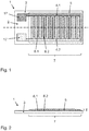
- the Fig. 1 and Fig. 2 show a schematic representation of an embodiment of a humidity sensor 1.
- the moisture sensor 1 comprises a nonconducting substrate 3 made of Al 2 O 3 , electrodes 4.1, 4.2 and a hygroscopic material 5.
- glass and SiO are also suitable as non-conductive substrate.
- the electrodes 4.1, 4.2 are formed comb-like and spaced from each other, wherein the electrodes 4.1, 4.2 are arranged and shifted from each other, that individual tines 6.1, 6.2 of both electrodes 4.1, 4.2 each complementary overlap.
- the electrodes 4.1, 4.2 consist of platinum or another noble metal, such as gold.
- the conductive electrode material of the electrodes 4.1, 4.2 may be vapor-deposited, sputtered or otherwise applied and has a layer thickness of some 5-10 microns thickness.
- the hygroscopic material 5 is applied together with admixed nanoparticles.
- the hygroscopic material 5 is preferably applied as a homogeneous layer.
- the amount of substance of the nanoparticles is chosen such that the viscosity at rest is gel-like, that is, that the hygroscopic material has gel character.
- the hygroscopic material 5 consists here, for example 85% phosphoric acid and admixed SiO 2 nanoparticles. Due to the gel character, the hygroscopic material 5 is uniformly and homogeneously applied, so that the layer thickness 8 in the measuring region 7 is largely the same everywhere. In addition, the applied hygroscopic material 5 remains dimensionally stable, so that the moisture sensor 1 can be transported and operated independently of position.
- the electrodes 4.1, 4.2 are provided at the ends with gold contacts 17 at which the humidity sensor 1, for example, with a measuring electronics, is contacted.
- the humidity sensor 1 is operated analogously to conventional humidity sensors in the prior art. To measure a DC or AC voltage is applied to the electrodes 4.1, 4.2 and measured a current. The measured current is a measure of an existing air humidity.
- Fig. 3 shows a characteristic 10 of a humidity sensor with a conventional hygroscopic material from the prior art.
- the abscissa shows the sensor signal in the form of a measured current and the ordinate the dew / frost point.
- the dew / frost point is thus a quantity which is equivalent to an absolute humidity at a given temperature. It generally applies that the dew / frost point increases when the humidity (partial pressure of water vapor) increases. For example, a dew / frost point of 9.3 ° C at an air temperature of 20 ° C corresponds to a relative humidity of 50%.
- the dew / frost point then increases to 16.4 ° C, this corresponds to a relative humidity of 80%. If, on the other hand, the relative humidity is 100%, then the dew / frost point is equal to the air temperature, in this example it is 20 ° C.
- Fig. 3 measurements of eight humidity sensors S1 to S8 are shown, wherein the humidity sensors S1 to S8 were each coated with 85% phosphoric acid as a hygroscopic material. Measurements were carried out under the following conditions: room temperature, normal pressure, 20 Nl / h (standard liters per hour) gas flow and a peak-to-peak measurement alternating voltage of 36 V at a frequency of 0.05 Hz.
- room temperature normal pressure
- 20 Nl / h standard liters per hour
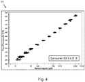
- Fig. 4 are characteristic curves 11 of humidity sensors with an embodiment of the hygroscopic material consisting of 85% phosphoric acid (7.5 ml) in water (6 ml), admixed SiO 2 nanoparticles (2 g) and admixed Sn (IV) O nanoparticles ( 2 g).
- the hygroscopic material was coated with a special brush on a substrate and two electrodes.
- the measurement conditions are the same as for the conventional humidity sensors: room temperature, normal pressure, 20 Nl / h (standard liters per hour) gas flow and an AC measurement voltage of 36 V at a frequency of 0.05 Hz.
- Fig. 4 shows measurement results of six humidity sensors according to the invention S9 to S15. It can be clearly seen that the scattering of the measurement results of the individual humidity sensors S9 to S15 in comparison to those in the Fig. 3 has decreased for the conventional humidity sensors. The characteristics have thus achieved a significantly improved reproducibility and comparability with each other by the hygroscopic material according to the invention.
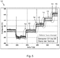
- Fig. 5 shows characteristic curves 12 for the reaction speed of the conventional humidity sensors. Shown is the dew / frost point determined from the measurements as a function of time. The dew / frost point was changed at intervals of 4 to 5 hours. Clearly visible is the settling 14 of the conventional humidity sensors S1 to S8. The humidity sensors S1 to S8 require approx. 20 to 30 minutes each until their final measured values 15 are reached. As in Fig. 3 Here, too, the scatter of the measured values of the individual conventional humidity sensors S1 to S8 can be clearly recognized again. In this case, both the final measured values 15 and the observed settling 14 scatter.
- Fig. 7 shows a schematic flow diagram of a method for producing a humidity sensor according to the invention.
- a surface-formed non-conductive substrate made of Al 2 O 3 is provided.
- the dimensions of the substrate are, for example, 3 ⁇ 1 cm 2 .
- two spaced-apart platinum electrodes are applied.
- the application can be done, for example, by vapor deposition or sputtering of platinum.
- other materials for the electrodes such as gold, rhodium or iridium, and other methods of application are possible.
- the applied electrodes are each formed in a comb-like manner, wherein the two comb-like spaced-apart electrodes are arranged and displaced from one another such that individual tines of both electrodes engage each other in a complementary manner.
- a length of the prongs is, for example, 0.8 cm and a width and distances between the prongs, for example, 200 microns each.
- Such an arrangement of the electrodes can be realized, for example, by using a shadow mask during sputtering or sputtering.
- SiO 2 nanoparticles are added to a hygroscopic material, for example 85% strength phosphoric acid in water.
- the admixed amount of SiO 2 nanoparticles is selected or adjusted in such a way that the hygroscopic material acquires gel character.
- the gel-like hygroscopic material provided with the SiO 2 nanoparticles is applied to a measuring region of the substrate and the electrodes by means of a special brush.
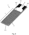
- FIGS. 8 to 10 schematically show further embodiments of the humidity sensor 1.
- the same reference numerals designate the same features and Terms as in the embodiment, which in Fig. 1 is shown.
- the hygroscopic material is not shown in the illustrations.
- the embodiments which in the FIGS. 9 to 10 are shown in each case in addition in each case a barrier 16.
- the barrier 16 is no longer necessary due to the improved hygroscopic material, such a barrier 16 may still have other advantages.
- the barrier 16 between the measuring area 7 and the gold contacts 17 serves, for example, to protect the gold contacts 17 from contact with the hygroscopic material.
- the barrier 16 at the edge regions of the measuring area 7 prevents, for example, that the hygroscopic material passes into these edge regions and there in the areas where the tines 6.1, 6.2 each end, lead to nonlinearities in the current measurement, which could affect the entire measurement.
- glass can be used as the material for the barriers 16.
- Fig. 11 a section of a schematic height profile 18 of a humidity sensor 1 is shown.
- the height profile of some tines 6.1, 6.2 can clearly be seen on the x-axis in the range between 2.5 and 5 mm.
- the tines 6.1, 6.2 each have a half-width of about 100 microns and a height of about 30 microns in this example.
Landscapes
- Chemical & Material Sciences (AREA)
- Life Sciences & Earth Sciences (AREA)
- Health & Medical Sciences (AREA)
- Physics & Mathematics (AREA)
- Chemical Kinetics & Catalysis (AREA)
- Electrochemistry (AREA)
- Molecular Biology (AREA)
- Analytical Chemistry (AREA)
- Biochemistry (AREA)
- General Health & Medical Sciences (AREA)
- General Physics & Mathematics (AREA)
- Immunology (AREA)
- Pathology (AREA)
- Investigating Or Analyzing Materials By The Use Of Fluid Adsorption Or Reactions (AREA)
- Investigating Or Analyzing Materials By The Use Of Electric Means (AREA)
Abstract
Description
- Die Erfindung betrifft einen Coulometrischen Feuchtesensor und ein Herstellungsverfahren für einen Coulometrischen Feuchtesensor.
- Die Feuchtigkeit in Gasen ist ein wichtiger Analyseparameter in der Prozessindustrie, unter anderem bei Gasherstellern, bei Gasversorgern und in der Halbleiterindustrie. Bereits geringe Mengen an Feuchtigkeit können beispielsweise Herstellungsverfahren in der Halbleiterindustrie negativ beeinflussen. Darüber hinaus ist die Feuchtigkeit bei der extraterrestrischen Forschung, insbesondere bei der Planetenforschung, von großem Interesse. Daher besteht ein großer Bedarf, die Spurenfeuchte in Gasen exakt bestimmen zu können.
- Für präzise Feuchtemessungen im Spurenfeuchtebereich, wird unter anderen das coulometrische Verfahren eingesetzt. Bei diesem Verfahren werden Wassermoleküle an einem selbst im Wesentlichen nicht leitfähigen hygroskopischen Material absorbiert. Über zwei getrennt voneinander ausgebildete Elektroden, die in Kontakt mit dem hygroskopischen Material angeordnet sind, wird eine Spannung angelegt. Hierdurch wird eine elektrolytische Dissoziation der Wassermoleküle in Wasserstoff und Sauerstoff ausgelöst. Aufgrund der Dissoziation und der dabei freiwerdenden 2 Elektronen pro dissoziertem Molekül kommt es zu einem Stromfluss, der proportional zu der Anzahl der dissoziierten Moleküle ist. Über eine Strommessung wird die Anzahl der bei der Dissoziation erzeugten Ladungsträger gemessen. Der gemessene Strom ist somit proportional zu der Anzahl der absorbierten und dissoziierten Moleküle.
- Das coulometrische Messprinzip wurde von Keidel entwickelt und ist in dem Artikel "Determination of Water by Direct Amperometric Measurement" in Journal Anal. Chem. 31 (1959), S. 2043-2048 beschrieben. Das dort beschriebene Messsystem besteht aus einem Sensor, der sich in einer Messzelle befindet, einem Massenflussregler, einer Gleichspannungsquelle und einem Strommessgerät. Durch den Massenflussregler wird ein definierter Volumenstrom über den Sensor geleitet. Der Sensor besteht aus einem Substrat, z.B. Glas oder Keramik, auf dem sich zwei Elektroden, im Allgemeinen aus Platin, befinden. Zwischen den Elektroden und in Kontakt mit diesen ist ein hygroskopisches Material angeordnet, welches vorzugsweise Phosphorpentoxid (P2O5) ist. Dieses absorbiert Wasser. Durch eine an den Elektroden anliegende Gleichspannung wird das absorbierte Wasser elektrolysiert und es entsteht ein dem absorbierten Wasser proportionaler Strom. Ein solches Messsystem wird häufig im Bypass betrieben, wie dies beispielsweise von R. Wernecke "Industrielle Feuchtemessung - Grundlagen, Messmethoden, technische Anwendungen" Weinheim: Wiley-VCH GmbH & Co. KGaA, 2003.-567 S. - ISBN 3-527-30285-9 auf Seite 118 und Seiten 307 und folgende beschrieben ist. Alternativ wird das über den Sensor geführte Messgas gegen die Atmosphäre abgeblasen.
- Aus der
DE 30 43 341 A1 ist ein Verfahren zur Herstellung eines Feuchtedetektors bekannt, bestehend aus einem elektrisch isolierenden Substrat, auf dem ein Elektrodensystem angebracht ist. Das Elektrodensystem umfasst ein Edelmetallelektrodenpaar, das durch eine elektrisch leitende feuchtigkeitsempfindliche auf dem Substrat vorhandene Schicht elektrisch miteinander verbunden ist. - Der Nachteil der vorgenannten Feuchtesensoren und Verfahren ist, dass häufig keine homogene Beschichtung der Oberfläche mit dem hygroskopischen Material möglich ist, da die hohe Oberflächenspannung des hygroskopischen Materials zur Tropfenbildung führt. Die Tropfenbildung führt dazu, dass Teile des Sensors nicht benetzt sind und/oder die benetzten Teile unterschiedliche Schichtdicken aufweisen. Darüber hinaus können derartige Sensoren nur in der räumlichen Ausrichtung betrieben werden, in der sie kalibriert wurden, da ansonsten das hygroskopische Material bei Lageänderung auf der Oberfläche des Sensors wandert und es zu einer Kennlinienverschiebung kommt oder es im ungünstigsten Fall sogar von der sensitiven Fläche des Feuchtesensors abfließt. Dadurch wird auch ein Transport des Sensors deutlich erschwert oder sogar unmöglich gemacht. Zur Vermeidung eines Abfließens wurden bisher Randbereiche des Sensors mit Barrieren versehen.
- Der Erfindung liegt das technische Problem zu Grunde, einen Feuchtesensor und ein Herstellungsverfahren für einen Feuchtesensor zu schaffen, bei denen die Benetzung der Oberfläche des Feuchtesensors verbessert ist.
- Die technische Aufgabe wird erfindungsgemäß durch einen Feuchtesensor mit den Merkmalen des Patentanspruchs 1 und ein Herstellungsverfahren mit den Merkmalen des Patentanspruchs 13 gelöst. Vorteilhafte Ausgestaltungen der Erfindung ergeben sich aus den Unteransprüchen.
- Dazu wird ein Feuchtesensor geschaffen, geeignet zum Messen einer Luftfeuchte, umfassend mindestens ein nichtleitendes flächig ausgebildetes Substrat, mindestens zwei an einer flächigen Seite des Substrats angeordnete voneinander beabstandete Elektroden, ein flächig auf der flächigen Seite des nichtleitenden Substrats und den Elektroden aufgetragenes die Elektroden verbindendes hygroskopisches Material, wobei eine Viskosität des hygroskopischen Materials durch mindestens einen beigemischten Feststoff erhöht ist.
- Ferner wird ein Verfahren zum Herstellen eines Feuchtesensors zur Verfügung gestellt, umfassend die folgenden Schritte: Bereitstellen eines nichtleitenden flächig ausgebildeten Substrats, Aufbringen von zwei voneinander beabstandeten Elektroden auf einer flächigen Seite des Substrats, flächiges Aufbringen eines hygroskopischen Materials auf die flächige Seite des nichtleitenden Substrats und die Elektroden, wobei dem hygroskopischen Material mindestens ein Feststoff zum Ändern einer Viskosität des hygroskopischen Materials beigemischt wird.
- Die Grundidee der Erfindung ist, dem hygroskopischen Material einen Feststoff beizumischen. Dabei handelt es sich vorzugsweise um kleine Feststoffpartikel, an denen das hygroskopische Material physisorbiert wird. Durch die Physisorption verändert sich die Viskosität des hygroskopischen Materials, ohne dass sich dessen Reaktionsfähigkeit verändert. Auf diese Weise wird die Oberflächenspannung des hygroskopischen Materials verändert und die Benetzung der Substrat- und Elektrodenoberfläche mit dem Material erfolgt homogener. Durch eine homogenere Benetzung sind Messungen der Luftfeuchte mit dem erfindungsgemäßen Feuchtesensor zuverlässiger, vergleichbarer und reproduzierbarer. Durch die erhöhte Viskosität kann das hygroskopische Material nicht mehr so leicht abfließen, wodurch sich die Transportfähigkeit eines fertig hergestellten erfindungsgemäßen Feuchtesensors deutlich verbessert. Darüber hinaus vereinfacht sich die Herstellung des Feuchtesensors, da Barrieren zum Verhindern eines Abfließens des hygroskopischen Materials an den Randbereichen nicht mehr notwendig sind.
- Als eine geeignete Klasse von Feststoffen haben sich anorganische Oxide, insbesondere Metalloxide erwiesen. Hier eignen sich insbesondere säurebeständige Oxide. Geeignete Metalloxide sind beispielsweise Oxide der Metalle Titan, Wolfram, Silizium, Yttrium, um einige vorteilhafte Feststoffe zu nennen.
- Ein besonders homogen ausgebildetes hygroskopisches Material kann erlangt werden, wenn die beigemischten Feststoffe möglichst kleine Abmessungen aufweisen. In einer vorteilhaften Ausführungsform ist deshalb vorgesehen, dass der mindestens eine beigemischte Feststoff Nanopartikel mit Abmessungen im Nanometerbereich aufweist.
- Dabei ist in einer besonders vorteilhaften Ausführungsform vorgesehen, dass die Nanopartikel SiO2-Nanopartikel sind. Dies hat den Vorteil, dass die Nanopartikel chemisch widerstandfähig, ungiftig und umweltverträglich sind.
- Dabei ist es bei der Herstellung eines Feuchtesensors vorteilhaft, wenn das hygroskopische Material gelartige Eigenschaften aufweist. Eine besonders vorteilhafte Ausführungsform sieht deshalb vor, dass eine Stoffmenge des mindestens einen beigemischten Feststoffs derart bemessen ist, dass die Viskosität des hygroskopischen Materials Gelcharakter aufweist. Dabei bezeichnet ein Gel ein viskoelastisches Fluid mit Gelcharakter. Zum Erlangen des Gelcharakters muss im komplexen Schubmodul des Fluids der Betrag des Speichermoduls größer sein als der Betrag des Verlustmoduls. Der Speichermodul steht dabei für den elastischen Anteil des komplexen Schubmoduls, wobei der Speichermodul proportional zum Anteil der Deformationsenergie ist, die in dem Material gespeichert wird und nach Entlastung wieder aus dem Material gewonnen werden kann. Der Verlustmodul beschreibt hingegen den viskosen Anteil des komplexen Schubmoduls und entspricht dem Verlustanteil der Energie, welche durch innere Reibung in Wärme umgewandelt wird. Weist das hygroskopische Material Gelcharakter auf, lässt es sich leicht verarbeiten und auf das Substrat auftragen, bleibt jedoch nach Auftragen weitgehend formbeständig auf der Oberfläche des Feuchtesensors erhalten. Dies ermöglicht eine Transportfähigkeit des Feuchtesensors. Darüber hinaus wird es möglich, den Feuchtesensor lageunabhängig zu betreiben.
- Das Auftragen des hygroskopischen Materials lässt sich besonders gut durchführen, wenn das hygroskopische Material während des Auftragens eine geringere Viskosität aufweist als nach Abschluss des Herstellungsverfahrens. Dies lässt sich über eine geschickte Auswahl des beigemischten Feststoffes realisieren. In einer weiteren vorteilhaften Ausführungsform ist dazu vorgesehen, dass der mindestens eine beigemischte Feststoff derart ausgebildet oder ausgewählt ist, dass das hygroskopische Material thixotrope Eigenschaften aufweist. Vor dem Aufbringen auf das Substrat und die Elektroden lässt sich die Viskosität des hygroskopischen Materials mit thixotropen Eigenschaften dann beispielsweise durch mechanische Beanspruchung verringern. Nach dem Aufbringen erhöht sich dann die Viskosität des hygroskopischen Materials wieder von selbst, so dass das aufgebrachte hygroskopische Material homogen und transportfähig ist.
- Die beigemischten Feststoffe, die eine Viskositätsänderung des hygroskopischen Materials bewirken, weisen einen Anteil von kleiner 20 Gewichtsprozent (gew.-%) in dem hygroskopischen Material des betriebsfertigen Sensors auf. Bevorzugt liegt dieser Anteil der die Viskosität ändernden Feststoffe bei 15 gew.-% ± 1 gew.-%.
- Natürlich können dem hygroskopischen Material weitere Feststoffe beigemischt werden. Diese können dabei derart ausgewählt sein, dass die elektrolytischen Eigenschaften des hygroskopischen Materials verändert sind oder werden. In einer weiteren vorteilhaften Ausführungsform ist deshalb vorgesehen, dass einer der beigemischten Feststoffe ein weiteres Oxid aufweist.
- In einer vorteilhaften Ausführungsform ist dabei insbesondere vorgesehen, dass das weitere Oxid ein Zinnoxid ist. Es hat sich gezeigt, dass optimale Ergebnisse bei einer Verwendung von Sn(IV)O als weiteres Oxid erlangt werden. Vergleichbare Ergebnisse wurden aber auch mit Oxiden wie beispielsweise Zr(VI)O oder Ti(IV)O erreicht.
- Dieses weitere Oxid, ändert die elektrischen Eigenschaften, jedoch nicht oder nur unwesentlich die Viskosität bzw. die vorzugsweise thixotrope Eigenschaft des hygroskopischen Materials.
- Einige Ausführungsformen sehen vor, das zusätzlich zu den vorzugsweise 15 gew.-% des zur Gelbildung zugefügten Oxids, beispielsweise in Form von SiO2-Nanopartikeln, ein weiteres die elektrischen Eigenschaften verbesserndes Oxid, beispielsweise Sn(IV)O, mit bis zu einem Anteil von weiteren 15 gew.-% dem hygroskopischen Material zugefügt wird. Die thixotrope Eigenschaft des hygroskopischen Materials wird hierdurch nicht gegenüber Ausführungsformen verändert, die nur das Oxid zur Gelbildung aufweisen, also beispielsweise 15 gew.-% SiO2-Nanopartikeln umfassen. Es wird eine Ansprechgeschwindigkeit des Sensors vergrößert, das heißt, die Zeitdauer verringert, die der Sensor benötigt, um einzuschwingen und/oder auf Änderungen der Spurenfeuchte mit einem erfassbaren Unterschied zu reagieren.
- Generell lässt sich das Messsignal vergrößern, wenn eine möglichst große Fläche zum Messen der Luftfeuchte verwendet wird. Deshalb ist in einer weiteren Ausführungsform vorgesehen, dass die zwei voneinander beabstandeten Elektroden jeweils kammartig ausgebildet sind, wobei die zwei kammartigen voneinander beabstandeten Elektroden derart angeordnet und gegeneinander verschoben sind, dass einzelne Zinken beider Elektroden jeweils komplementär ineinander greifen.
- Zur Erlangung einer vorgegebenen Schichtdicke des hygroskopischen Materials ist es wichtig, dass die Schichtdicke sehr genau eingestellt und reproduziert werden kann. Dies lässt sich mit Hilfe eines speziellen Pinsels erreichen. In einer besonders vorteilhaften Ausführungsform ist deshalb vorgesehen, dass das hygroskopische Material mit dem mindestens einen beigemischten Feststoff mit Hilfe eines speziellen Pinsels auf das Substrat und die Elektroden flächig aufgebracht wird. Dies ermöglicht ein einfaches und uniformes Aufbringen des hygroskopischen Materials zusammen mit den beigemischten Feststoffen. Durch das Aufbringen des hygroskopischen Materials in einer vorgegebenen Schichtdicke kann eine verbesserte Kennlinienübereinstimmung bzw. Vergleichbarkeit und Reproduzierbarkeit mehrerer Feuchtesensoren untereinander realisiert werden. Bei dem speziellen Pinsel handelt es sich beispielsweise um einen Silikonpinsel mit keilförmiger Spitze. In der Form ist der spezielle Pinsel vergleichbar mit der Spitze eines Schraubendrehers für Schlitzschrauben. Die Spitze des Pinsels ist elastisch ausgebildet und ermöglicht dadurch ein homogenes und für den Sensor schonendes Auftragen des Gels auf den Sensor.
- In einer Ausführungsform ist vorgesehen, dass das hygroskopische Material ein hydrophiler Elektrolyt ist.
- In einer Ausführungsform ist vorgesehen, dass der hydrophile Elektrolyt eine Säure aufweist.
- Insbesondere ist bei einer Ausführungsform vorgesehen, dass die Säure im hydrophilen Elektrolyt Phosphorsäure ist.
- In einer weiteren Ausführungsform ist vorgesehen, dass das Substrat aus Al2O3 besteht.
- Als vorteilhaft für eine Langzeitstabilität hat es sich erwiesen, den Feuchtesensor mit wechselnder Polarität der Spannung zu betreiben. Beispielsweise kann eine Änderung der Spannungsrichtung alle 10 Sekunden vorgenommen werden. Abweichende Zeitdauern können selbstverständlich gewählt werden. Wichtig ist, dass ein reproduzierbares Messergebnis in der Zeitspanne zwischen den Änderungen der Polarität erfasst werden kann. Ein Betrieb mit sinusförmiger Wechselspannung von 50 Hz oder mehr gestattet dieses nicht.
- Nachfolgend wird die Erfindung anhand bevorzugter Ausführungsbeispiele unter Bezugnahme auf die Figuren näher erläutert. Hierbei zeigen:
- Fig. 1
- eine schematische Darstellung einer Ausführungsform eines erfindungsgemäßen Feuchtesensors in Draufsicht auf die flächige Oberseite;
- Fig. 2
- eine schematische Schnittdarstellung durch die Ausführungsform des in
Fig. 1 gezeigten Feuchtesensors; - Fig. 3
- Kennlinien von Feuchtesensoren mit einem herkömmlichen hygroskopischen Material entsprechend des Stands der Technik;
- Fig. 4
- Kennlinien von Feuchtesensoren mit einem erfindungsgemäßen hygroskopischen Material und beigemischten SiO2-Nanopartikeln;
- Fig. 5
- Kennlinien zur Reaktionsgeschwindigkeit der Feuchtesensoren aus
Fig. 3 mit dem herkömmlichen hygroskopischen Material gemäß dem Stand der Technik; - Fig. 6
- Kennlinien zur Reaktionsgeschwindigkeit der Feuchtesensoren aus
Fig. 4 mit dem erfindungsgemäßen hygroskopischen Material und beigemischten SiO2-Nanopartikeln; - Fig. 7
- ein schematisches Ablaufdiagramm des Verfahrens zur Herstellung eines erfindungsgemäßen Feuchtesensors;
- Fig. 8
- eine schematische Darstellung einer Ausführungsform eines Feuchtesensors in perspektivischer Darstellung auf die flächige Oberseite;
- Fig. 9
- eine schematische Darstellung einer Ausführungsform eines Feuchtesensors in Draufsicht auf die flächige Oberseite;
- Fig. 10
- eine schematische Darstellung einer Ausführungsform eines Feuchtesensors in Draufsicht auf die flächige Oberseite:
- Fig. 11
- einen Ausschnitt eines schematischen Höhenprofils eines Feuchtesensors.
- Die
Fig. 1 und Fig. 2 zeigen eine schematische Darstellung einer Ausführungsform eines Feuchtesensors 1. Dabei ist eine Draufsicht (Fig. 1 ) auf eine flächig ausgebildete Oberfläche 2 des Feuchtsensors 1 und ein Schnitt (Fig. 2 ) durch den Feuchtesensor 1 gezeigt. Der Feuchtesensor 1 umfasst ein nichtleitendes Substrat 3 aus Al2O3, Elektroden 4.1, 4.2 und ein hygroskopisches Material 5. Als nicht leitendes Substrat eignen sich prinzipiell auch Glas und SiO. - Die Elektroden 4.1, 4.2 sind kammartig und voneinander beabstandet ausgebildet, wobei die Elektroden 4.1, 4.2 derart angeordnet und gegeneinander verschoben sind, dass einzelne Zinken 6.1, 6.2 beider Elektroden 4.1, 4.2 jeweils komplementär ineinander greifen. Die Elektroden 4.1, 4.2 bestehen dabei aus Platin oder einem anderen Edelmetall, wie zum Beispiel Gold. Das leitende Elektrodenmaterial der Elektroden 4.1, 4.2 kann dabei aufgedampft, aufgesputtert oder anders aufgebracht worden sein und weist eine Schichtdicke von einigen 5-10 µm Dicke auf. Innerhalb eines Messbereichs 7 des Feuchtesensors 1 ist das hygroskopische Material 5 zusammen mit beigemischten Nanopartikeln aufgebracht. Das hygroskopische Material 5 ist dabei vorzugsweise als homogene Schicht aufgebracht. Die Stoffmenge der Nanopartikel ist dabei derart gewählt, dass die Viskosität in Ruhe gelartig ist, das heißt dass das hygroskopische Material Gelcharakter aufweist. Das hygroskopische Material 5 besteht hier beispielsweise aus 85%iger Phosphorsäure und beigemischten SiO2-Nanopartikeln. Durch den Gelcharakter ist das hygroskopische Material 5 uniform und homogen aufgetragen, so dass die Schichtdicke 8 im Messbereich 7 überall weitgehend gleich ist. Darüber hinaus bleibt das aufgetragene hygroskopische Material 5 formbeständig, so dass der Feuchtesensor 1 transportiert und lageunabhängig betrieben werden kann.
- Zur Erleichterung einer Kontaktierung sind die Elektroden 4.1, 4.2 an den Enden mit Goldkontakten 17 versehen, an denen der Feuchtesensor 1, beispielsweise mit einer Messelektronik, kontaktiert wird.
- Der Feuchtesensor 1 wird analog zu herkömmlichen Feuchtesensoren im Stand der Technik betrieben. Zum Messen wird eine Gleich- oder Wechselspannung an die Elektroden 4.1, 4.2 angelegt und ein Strom gemessen. Der gemessene Strom ist ein Maß für eine vorhandene Luftfeuchte.
-
Fig. 3 zeigt eine Kennlinie 10 eines Feuchtesensors mit einem herkömmlichen hygroskopischen Material aus dem Stand der Technik. Dabei ist auf der Abszisse das Sensorsignal in Form eines gemessenen Stromes und auf der Ordinate der Tau-/Frostpunkt gezeigt. Bei der Tau-/Frostpunkttemperatur beträgt die relative Luftfeuchte der Luft 100 %. Der Tau-/Frostpunkt ist somit eine Größe, welche äquivalent zu einer absoluten Luftfeuchte bei einer gegebenen Temperatur ist. Dabei gilt allgemein, dass sich der Tau-/Frostpunkt erhöht, wenn die Luftfeuchte (Partialdruck von Wasserdampf) ansteigt. So entspricht ein Tau-/Frostpunkt von 9,3°C bei einer Lufttemperatur von 20°C beispielsweise einer relativen Luftfeuchte von 50 %. Erhöht sich der Tau-/Frostpunkt dann beispielsweise auf 16,4°C, so entspricht dies einer relativen Luftfeuchte von 80 %. Beträgt hingegen die relative Luftfeuchte 100 %, so ist der Tau-/Frostpunkt gleich der Lufttemperatur, liegt im Beispiel hier also bei 20°C. - In
Fig. 3 sind Messergebnisse von acht Feuchtsensoren S1 bis S8 gezeigt, wobei die Feuchtesensoren S1 bis S8 jeweils mit 85%iger Phosphorsäure als hygroskopisches Material beschichtet wurden. Gemessen wurde unter folgenden Bedingungen: Raumtemperatur, Normaldruck, 20 Nl/h (Normliter pro Stunde) Gasstrom und einer Spitze-zu-Spitze-Messwechselspannung von 36 V bei eine Frequenz von 0,05 Hz. Deutlich in derFig. 3 zu erkennen ist eine breite Streuung der Messergebnisse der verschiedenen Feuchtesensoren S1 bis S8. Eine Vergleichbarkeit der Kennlinien ist somit bei den herkömmlichen Feuchtesensoren im Stand der Technik nicht gegeben. - In
Fig. 4 sind Kennlinien 11 von Feuchtesensoren mit einer Ausführungsform des hygroskopischen Materials, bestehend aus 85%iger Phosphorsäure (7,5 ml) in Wasser (6 ml), beigemischten SiO2-Nanopartikeln (2 g) und beigemischten Sn(IV)O-Nanopartikeln (2 g), gezeigt. Das hygroskopische Material wurde mit einem speziellen Pinsel auf ein Substrat und zwei Elektroden gestrichen. Die Messbedingungen sind die gleichen wie für die herkömmlichen Feuchtesensoren: Raumtemperatur, Normaldruck, 20 Nl/h (Normliter pro Stunde) Gasstrom und einer Messwechselspannung von 36 V bei eine Frequenz von 0,05 Hz. -
Fig. 4 zeigt Messergebnisse von sechs erfindungsgemäßen Feuchtesensoren S9 bis S15. Dabei ist deutlich zu erkennen, dass die Streuung der Messergebnisse der einzelnen Feuchtesensoren S9 bis S15 im Vergleich zu den in derFig. 3 für die herkömmlichen Feuchtesensoren gezeigten Messergebnissen abgenommen hat. Die Kennlinien haben somit durch das erfindungsgemäße hygroskopische Material eine deutlich verbesserte Reproduzierbarkeit und Vergleichbarkeit untereinander erlangt. -
Fig. 5 zeigt Kennlinien 12 zur Reaktionsgeschwindigkeit der herkömmlichen Feuchtesensoren. Gezeigt ist der aus den Messungen bestimmte Tau-/Frostpunkt als Funktion der Zeit. Der Tau-/Frostpunkt wurde dabei jeweils in Abständen von 4 bis 5 Stunden verändert. Deutlich zu erkennen ist das Einschwingen 14 der herkömmlichen Feuchtesensoren S1 bis S8. Die Feuchtesensoren S1 bis S8 benötigen bis zum finalen Erreichen ihrer Endmesswerte 15 jeweils ca. 20 bis 30 Minuten. Wie inFig. 3 ist hier ebenfalls wieder deutlich die Streuung der Messwerte der einzelnen herkömmlichen Feuchtesensoren S1 bis S8 zu erkennen. Dabei streuen sowohl die Endmesswerte 15 als auch das beobachtete Einschwingen 14. - Zum Vergleich zeigt
Fig. 6 Kennlinien 13 der Ausführungsform der Feuchtesensoren S9 bis S15. Hier wurde die Luftfeuchte jeweils in Abständen von 3 bis 5 Stunden verändert. Im Vergleich zu den Kennlinien 12 der herkömmlichen Feuchtesensoren inFig. 5 lässt sich beobachten, dass sich das Einschwingen 14 der Feuchtesensoren S9 bis S15 nach einer Änderung der Luftfeuchte deutlich verkürzt hat. So erreichen die erfindungsgemäßen Feuchtesensoren S9 bis S15 jeweilige Endmesswerte 15 bereits nach weniger als 5 Minuten nach der Änderung der Luftfeuchte. Die Reaktionsgeschwindigkeit der erfindungsgemäßen Feuchtesensoren S9 bis S15 ist gegenüber den herkömmlichen Sensoren S1 bis S8 um fast eine Größenordnung verbessert. Darüber hinaus erkennt man auch hier die Übereinstimmung der Endmesswerte 15 der einzelnen erfindungsgemäßen Feuchtesensoren S9 bis S15. Die Messerergebnisse sind durch das erfindungsgemäße hygroskopische Material somit besser vergleichbar und besser reproduzierbar geworden, sowohl was die Endmesswerte 15 als auch was das Einschwingen 14 angeht. -
Fig. 7 zeigt ein schematisches Ablaufdiagramm eines Verfahrens zum Herstellen eines erfindungsgemäßen Feuchtesensors. Im ersten Verfahrensschritt 101 wird ein flächig ausgebildetes nichtleitendes Substrat aus Al2O3 bereitgestellt. Die Abmessungen des Substrats betragen beispielsweise 3 x 1 cm2. Auf eine Oberseite des Substrats werden im nächsten Verfahrensschritt 102 zwei voneinander beabstandete Platin-Elektroden aufgebracht. Das Aufbringen kann beispielsweise durch Bedampfen mit oder Aufsputtern von Platin erfolgen. Prinzipiell sind aber auch andere Materialien für die Elektroden, beispielsweise Gold, Rhodium oder Iridium, sowie andere Methoden zum Aufbringen möglich. Die aufgebrachten Elektroden sind dabei jeweils kammartig ausgebildet, wobei die zwei kammartigen voneinander beabstandeten Elektroden derart angeordnet und gegeneinander verschoben sind, dass einzelne Zinken beider Elektroden jeweils komplementär ineinander greifen. Eine Länge der Zinken beträgt beispielsweise 0,8 cm und eine Breite und Abstände zwischen den Zinken beispielsweise jeweils 200 µm. Eine derartige Anordnung der Elektroden kann beispielsweise durch eine Verwendung einer Schattenmaske während des Bedampfens oder Aufsputterns realisiert werden. Im nächsten Verfahrensschritt 103 werden einem hygroskopischen Material, beispielsweise 85%iger Phosphorsäure in Wasser, SiO2-Nanopartikel beigemischt. Dabei wird die beigemischte Stoffmenge der SiO2-Nanopartikel derart ausgewählt oder eingestellt, dass das hygroskopische Material Gelcharakter bekommt. Im letzten Verfahrensschritt 104 wird das gelartige mit den SiO2-Nanopartikeln versehene hygroskopische Material mit Hilfe eines speziellen Pinsels auf einen Messbereich des Substrats und der Elektroden aufgebracht. - Die
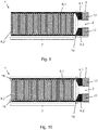
Figuren 8 bis 10 zeigen schematisch weitere Ausführungsformen des Feuchtesensors 1. Gleiche Bezugszeichen bezeichnen dabei die gleichen Merkmale und Begriffe wie in der Ausführungsform, welche inFig. 1 gezeigt ist. Das hygroskopische Material ist in den Darstellungen nicht gezeigt. Im Gegensatz zu den Ausführungsformen, welche in denFiguren 1 und8 gezeigt sind, weisen die Ausführungsformen, welche in denFiguren 9 bis 10 gezeigt sind, in verschiedenen Bereichen jeweils zusätzlich eine Barriere 16 auf. Obwohl die Barriere 16 auf Grund des verbesserten hygroskopischen Materials nicht mehr notwendig ist, kann eine solche Barriere 16 trotzdem weitere Vorteile aufweisen. - Die Barriere 16 zwischen dem Messbereich 7 und den Goldkontakten 17 (
Figuren 9 und 10 ) dient beispielsweise dazu, die Goldkontakte 17 vor einem Kontakt mit dem hygroskopischen Material zu schützen. Die Barriere 16 an den Randbereichen des Messbereichs 7 (Fig. 10 ) verhindert beispielsweise, dass das hygroskopische Material in diese Randbereiche gelangt und dort in den Bereichen, wo die Zinken 6.1, 6.2 jeweils enden, zu Nichtlinearitäten bei der Strommessung führen, welche die gesamte Messung beeinflussen könnten. Als Material für die Barrieren 16 kann beispielsweise Glas verwendet werden. - In
Fig. 11 ist ein Ausschnitt aus einem schematischen Höhenprofil 18 eines Feuchtesensors 1 gezeigt. Dabei ist auf der x-Achse im Bereich zwischen 2,5 und 5 mm deutlich das Höhenprofil einiger Zinken 6.1, 6.2 zu sehen. Die Zinken 6.1, 6.2 haben in diesem Beispiel jeweils eine Halbwertsbreite von ca. 100 µm und eine Höhe von ca. 30 µm. -
- 1
- Feuchtesensor
- 2
- Oberfläche
- 3
- Substrat
- 4.1
- Elektrode
- 4.2
- Elektrode
- 5
- hygroskopisches Material
- 6.1
- Zinke
- 6.2
- Zinke
- 7
- Messbereich
- 8
- Schichtdicke
- 10
- Kennlinien
- 11
- Kennlinien
- 12
- Kennlinien
- 13
- Kennlinien
- 14
- Einschwingen
- 15
- Endmesswert
- 16
- Barriere
- 17
- Goldkontakt
- 18
- Höhenprofil
- S1-S8
- herkömmlicher Feuchtesensor
- S9-S15
- erfindungsgemäßer Feuchtesensor
- 101-104
- Verfahrensschritte
Claims (15)
- Feuchtesensor (1), geeignet zum Messen einer Luftfeuchte, umfassend:mindestens ein nichtleitendes flächig ausgebildetes Substrat (3),mindestens zwei an einer flächigen Seite des Substrats (3) angeordnete voneinander beabstandete Elektroden (4.1, 4.2),ein flächig auf der flächigen Seite des nichtleitenden Substrats (3) und den Elektroden (4.1, 4.2) aufgetragenes die Elektroden (4.1, 4.2) verbindendes hygroskopisches Material (5),dadurch gekennzeichnet, dasseine Viskosität des hygroskopischen Materials (5) durch mindestens einen beigemischten Feststoff erhöht ist.
- Feuchtesensor (1) nach einem der vorangegangenen Ansprüche, dadurch gekennzeichnet, dass der mindestens eine beigemischte Feststoff Nanopartikel aufweist.
- Feuchtesensor, nach Anspruch 2, dadurch gekennzeichnet, dass die Nanopartikel SiO2-Nanopartikel sind.
- Feuchtesensor (1) nach einem der vorangegangenen Ansprüche, dadurch gekennzeichnet, dass eine Stoffmenge des mindestens einen beigemischten Feststoffs derart bemessen ist, dass die Viskosität des hygroskopischen Materials (5) Gelcharakter aufweist.
- Feuchtesensor (1) nach einem der vorangegangenen Ansprüche, dadurch gekennzeichnet, dass der mindestens eine beigemischte Feststoff derart ausgebildet oder ausgewählt ist, dass das hygroskopische Material (5) thixotrope Eigenschaften aufweist.
- Feuchtesensor (1) nach einem der vorangegangenen Ansprüche, dadurch gekennzeichnet, dass einer der beigemischten Feststoffe ein weiteres Oxid aufweist.
- Feuchtesensor (1) nach Anspruch 6, dadurch gekennzeichnet, dass das weitere Oxid ein Zinnoxid ist.
- Feuchtesensor (1) nach einem der vorangegangen Ansprüche, dadurch gekennzeichnet, dass die zwei voneinander beabstandeten Elektroden (4.1, 4.2) jeweils kammartig ausgebildet sind, wobei die zwei kammartigen voneinander beabstandeten Elektroden (4.1, 4.2) derart angeordnet und gegeneinander verschoben sind, dass einzelne Zinken (6) beider Elektroden (4.1, 4.2) jeweils komplementär ineinander greifen.
- Feuchtesensor (1) nach einem der vorangegangen Ansprüche, dadurch gekennzeichnet, dass das hygroskopische Material (5) ein hydrophiler Elektrolyt ist.
- Feuchtesensor (1) nach Anspruch 9, dadurch gekennzeichnet, dass der hydrophile Elektrolyt eine Säure aufweist.
- Feuchtesensor (1) nach Anspruch 10, dadurch gekennzeichnet, dass die Säure im hydrophilen Elektrolyt Phosphorsäure ist.
- Feuchtesensor (1) nach einem der vorangegangenen Ansprüche, dadurch gekennzeichnet, dass das Substrat (3) aus Al2O3 besteht.
- Verfahren zum Herstellen eines Feuchtesensors (1), umfassend die folgenden Schritte:Bereitstellen eines nichtleitenden flächig ausgebildeten Substrats (3),Aufbringen von zwei voneinander beabstandeten Elektroden (4.1, 4.2) auf einer flächigen Seite (2) des Substrats (3),flächiges Aufbringen eines hygroskopischen Materials (5) auf die flächige Seite (2) des nichtleitenden Substrats (3) und die Elektroden (4.1, 4.2),dadurch gekennzeichnet, dassdem hygroskopischen Material (5) mindestens ein Feststoff zum Ändern einer Viskosität des hygroskopischen Materials (5) beigemischt wird.
- Verfahren nach Anspruch 13, dadurch gekennzeichnet, dass als der mindestens eine beigemischte Feststoff SiO2-Nanopartikel aufweist, wobei eine Stoffmenge der SiO2-Nanopartikel derart bemessen wird, dass die Viskosität des hygroskopischen Materials (5) Gelcharakter aufweist.
- Verfahren nach Anspruch 13 oder 14, dadurch gekennzeichnet, dass das hygroskopische Material (5) mit dem mindestens einen beigemischten Feststoff mit Hilfe eines speziellen Pinsels auf das Substrat und die Elektroden flächig aufgebracht wird.
Applications Claiming Priority (1)
| Application Number | Priority Date | Filing Date | Title |
|---|---|---|---|
| DE102016206445.2A DE102016206445B4 (de) | 2016-04-15 | 2016-04-15 | Coulometrischer Feuchtesensor mit gelförmigem Elektrolyt und Herstellungsverfahren für einen Coulometrischen Feuchtesensor mit gelförmigem Elektrolyt |
Publications (2)
| Publication Number | Publication Date |
|---|---|
| EP3232188A1 true EP3232188A1 (de) | 2017-10-18 |
| EP3232188B1 EP3232188B1 (de) | 2021-02-17 |
Family
ID=58548627
Family Applications (1)
| Application Number | Title | Priority Date | Filing Date |
|---|---|---|---|
| EP17166618.3A Active EP3232188B1 (de) | 2016-04-15 | 2017-04-13 | Coulometrischer feuchtesensor mit gelförmigem elektrolyt und herstellungsverfahren für einen coulometrischen feuchtesensor mit gelförmigem elektrolyt |
Country Status (2)
| Country | Link |
|---|---|
| EP (1) | EP3232188B1 (de) |
| DE (1) | DE102016206445B4 (de) |
Families Citing this family (1)
| Publication number | Priority date | Publication date | Assignee | Title |
|---|---|---|---|---|
| DE102018205347B4 (de) | 2018-04-10 | 2026-02-05 | Deutsches Zentrum für Luft- und Raumfahrt e.V. | Verfahren zum Bestimmen einer Materialfeuchte in einer Materialprobe und Materialfeuchtemesszelle |
Citations (5)
| Publication number | Priority date | Publication date | Assignee | Title |
|---|---|---|---|---|
| DE3043341A1 (de) | 1979-11-22 | 1981-08-27 | Naamloze Vennootschap Philips' Gloeilampenfabrieken, Eindhoven | Verfahren zur herstellung von feuchtedetektoren |
| US4621249A (en) * | 1981-09-30 | 1986-11-04 | Mitsubishi Denki Kabushiki Kaisha | Moisture sensitive element |
| US4800000A (en) * | 1987-06-03 | 1989-01-24 | Manufacturers Engineering Equipment Corp. | Low level moisture measurement system and method |
| DE10208648A1 (de) * | 2002-02-28 | 2003-09-11 | Bosch Gmbh Robert | Sensor zur Bestimmung von Gasen und Verfahren zur Herstellung desselben |
| EP2264445A1 (de) * | 2009-06-15 | 2010-12-22 | Deutsches Zentrum für Luft- und Raumfahrt e.V. (DLR) | Coulometrischer Feuchtesensor mit Wechselspannungsquelle |
Family Cites Families (3)
| Publication number | Priority date | Publication date | Assignee | Title |
|---|---|---|---|---|
| US3014858A (en) * | 1958-02-03 | 1961-12-26 | Cons Electrodynamics Corp | Electrolytic film |
| GB2140566B (en) * | 1983-05-26 | 1986-10-22 | Teledyne Ind | Powdered liquid electrolyte |
| EP0366262A3 (de) * | 1988-10-24 | 1990-09-12 | Imperial Chemical Industries Plc | Gasnachweissystem |
-
2016
- 2016-04-15 DE DE102016206445.2A patent/DE102016206445B4/de active Active
-
2017
- 2017-04-13 EP EP17166618.3A patent/EP3232188B1/de active Active
Patent Citations (5)
| Publication number | Priority date | Publication date | Assignee | Title |
|---|---|---|---|---|
| DE3043341A1 (de) | 1979-11-22 | 1981-08-27 | Naamloze Vennootschap Philips' Gloeilampenfabrieken, Eindhoven | Verfahren zur herstellung von feuchtedetektoren |
| US4621249A (en) * | 1981-09-30 | 1986-11-04 | Mitsubishi Denki Kabushiki Kaisha | Moisture sensitive element |
| US4800000A (en) * | 1987-06-03 | 1989-01-24 | Manufacturers Engineering Equipment Corp. | Low level moisture measurement system and method |
| DE10208648A1 (de) * | 2002-02-28 | 2003-09-11 | Bosch Gmbh Robert | Sensor zur Bestimmung von Gasen und Verfahren zur Herstellung desselben |
| EP2264445A1 (de) * | 2009-06-15 | 2010-12-22 | Deutsches Zentrum für Luft- und Raumfahrt e.V. (DLR) | Coulometrischer Feuchtesensor mit Wechselspannungsquelle |
Non-Patent Citations (2)
| Title |
|---|
| "Determination of Water by Direct Amperometric Measurement", JOURNAL ANAL. CHEM., vol. 31, 1959, pages 2043 - 2048 |
| R. WERNECKE: "Industrielle Feuchtemessung - Grundlagen, Messmethoden, technische Anwendungen", 2003, WILEY-VCH GMBH & CO. KGAA, pages: 118,307 |
Also Published As
| Publication number | Publication date |
|---|---|
| DE102016206445A1 (de) | 2017-10-19 |
| DE102016206445B4 (de) | 2023-11-16 |
| EP3232188B1 (de) | 2021-02-17 |
Similar Documents
| Publication | Publication Date | Title |
|---|---|---|
| DE1809622C2 (de) | Meßsonde zum Erfassen von Gasgehalten | |
| DE19618935C2 (de) | Gassensor und Verfahren zur Herstellung eines Gassensors | |
| DE2501812C2 (de) | Meßanordnung zur Messung der Leitfähigkeit eines Elektrolyten | |
| DE10359173B4 (de) | Messvorrichtung mit mehreren auf einem Substrat angeordneten potentiometrischen Elektrodenpaaren | |
| EP3754329B1 (de) | Wasserstoffsensor und verfahren zu dessen herstellung, messvorrichtung und verfahren zum messen einer wasserstoffkonzentration | |
| EP2220482B1 (de) | Gassensor mit einer verbesserten selektivität | |
| EP1236038A1 (de) | Kapazitiver sensor | |
| EP0046989B1 (de) | Selektiver Dünnschicht-Gassensor hoher Empfindlichkeit und Stabilität zum Nachweis und zur Messung von gasförmigen Kohlenwasserstoff-Verunreinigungen in der Luft auf der Basis von Wolframoxid (WOx)-Halbleitern, sowie ein Verfahren zu seiner Herstellung | |
| EP3035040A1 (de) | Gassensor, messelement für einen gassensor und verfahren zur herstellung eines messelementes | |
| DE102019108890A1 (de) | Sensorelement für einen potentiometrischen Sensor | |
| DE102014210122B4 (de) | Vorrichtung zum Bestimmen eines Werts einer zu messenden Eigenschaft eines Fluids, Verfahren zum Betreiben einer Vorrichtung zum Bestimmen eines Werts einer zu messenden Eigenschaft eines Fluids | |
| DE2950383A1 (de) | Elektrochemische elektrode sowie verfahren zur ausbildung einer auf ionen ansprechenden membran fuer eine elektrochemische elektrode sowie verfahren zur herstellung einer elektrochemischen elektrode | |
| EP3232188B1 (de) | Coulometrischer feuchtesensor mit gelförmigem elektrolyt und herstellungsverfahren für einen coulometrischen feuchtesensor mit gelförmigem elektrolyt | |
| DE2820858C2 (de) | Gas-Meßfühler | |
| WO2007036454A1 (de) | Gassensor | |
| WO1991016624A1 (de) | Verfahren zur bestimmung von gaskonzentrationen und gassensor mit festem elektrolyten | |
| DE10318115A1 (de) | Potentiometrische Sensoreinrichtung | |
| DE2554997A1 (de) | Verfahren zum herstellen einer bindung zwischen metallen und festen elektrolytischen stoffen | |
| EP2264445B1 (de) | Coulometrischer Feuchtesensor und entsprechendes Verfahren | |
| DE2538739A1 (de) | Ionensensitive elektrode | |
| DE102019216113A1 (de) | Keramisches Sensorelement für einen Abgassensor, Verfahren zur Herstellung und Betriebsverfahren | |
| DE3416945A1 (de) | Feuchtigkeitssensor und verfahren zu seiner herstellung | |
| DE4025785A1 (de) | Messeinrichtung fuer ph-werte | |
| DE19953218C2 (de) | Indikatorelektrode mit einer sensitiven Oberfläche und Verwendung hierfür | |
| EP1717574B1 (de) | Detektion der Abdichtung einer biologischen Substanz auf einem Träger mittels Rauschanalyse |
Legal Events
| Date | Code | Title | Description |
|---|---|---|---|
| PUAI | Public reference made under article 153(3) epc to a published international application that has entered the european phase |
Free format text: ORIGINAL CODE: 0009012 |
|
| STAA | Information on the status of an ep patent application or granted ep patent |
Free format text: STATUS: THE APPLICATION HAS BEEN PUBLISHED |
|
| AK | Designated contracting states |
Kind code of ref document: A1 Designated state(s): AL AT BE BG CH CY CZ DE DK EE ES FI FR GB GR HR HU IE IS IT LI LT LU LV MC MK MT NL NO PL PT RO RS SE SI SK SM TR |
|
| AX | Request for extension of the european patent |
Extension state: BA ME |
|
| RIN1 | Information on inventor provided before grant (corrected) |
Inventor name: LOREK, ANDREAS Inventor name: WOLTER, DAVID |
|
| STAA | Information on the status of an ep patent application or granted ep patent |
Free format text: STATUS: REQUEST FOR EXAMINATION WAS MADE |
|
| 17P | Request for examination filed |
Effective date: 20180126 |
|
| RBV | Designated contracting states (corrected) |
Designated state(s): AL AT BE BG CH CY CZ DE DK EE ES FI FR GB GR HR HU IE IS IT LI LT LU LV MC MK MT NL NO PL PT RO RS SE SI SK SM TR |
|
| GRAP | Despatch of communication of intention to grant a patent |
Free format text: ORIGINAL CODE: EPIDOSNIGR1 |
|
| STAA | Information on the status of an ep patent application or granted ep patent |
Free format text: STATUS: GRANT OF PATENT IS INTENDED |
|
| INTG | Intention to grant announced |
Effective date: 20200722 |
|
| GRAJ | Information related to disapproval of communication of intention to grant by the applicant or resumption of examination proceedings by the epo deleted |
Free format text: ORIGINAL CODE: EPIDOSDIGR1 |
|
| STAA | Information on the status of an ep patent application or granted ep patent |
Free format text: STATUS: REQUEST FOR EXAMINATION WAS MADE |
|
| GRAS | Grant fee paid |
Free format text: ORIGINAL CODE: EPIDOSNIGR3 |
|
| STAA | Information on the status of an ep patent application or granted ep patent |
Free format text: STATUS: GRANT OF PATENT IS INTENDED |
|
| GRAP | Despatch of communication of intention to grant a patent |
Free format text: ORIGINAL CODE: EPIDOSNIGR1 |
|
| INTG | Intention to grant announced |
Effective date: 20201204 |
|
| GRAA | (expected) grant |
Free format text: ORIGINAL CODE: 0009210 |
|
| STAA | Information on the status of an ep patent application or granted ep patent |
Free format text: STATUS: THE PATENT HAS BEEN GRANTED |
|
| AK | Designated contracting states |
Kind code of ref document: B1 Designated state(s): AL AT BE BG CH CY CZ DE DK EE ES FI FR GB GR HR HU IE IS IT LI LT LU LV MC MK MT NL NO PL PT RO RS SE SI SK SM TR |
|
| REG | Reference to a national code |
Ref country code: GB Ref legal event code: FG4D Free format text: NOT ENGLISH |
|
| REG | Reference to a national code |
Ref country code: CH Ref legal event code: EP |
|
| REG | Reference to a national code |
Ref country code: DE Ref legal event code: R096 Ref document number: 502017009309 Country of ref document: DE |
|
| REG | Reference to a national code |
Ref country code: AT Ref legal event code: REF Ref document number: 1362103 Country of ref document: AT Kind code of ref document: T Effective date: 20210315 |
|
| REG | Reference to a national code |
Ref country code: IE Ref legal event code: FG4D Free format text: LANGUAGE OF EP DOCUMENT: GERMAN |
|
| REG | Reference to a national code |
Ref country code: DE Ref legal event code: R082 Ref document number: 502017009309 Country of ref document: DE Representative=s name: PATENTANWAELTE BRESSEL UND PARTNER MBB, DE |
|
| REG | Reference to a national code |
Ref country code: LT Ref legal event code: MG9D |
|
| REG | Reference to a national code |
Ref country code: NL Ref legal event code: MP Effective date: 20210217 |
|
| PG25 | Lapsed in a contracting state [announced via postgrant information from national office to epo] |
Ref country code: BG Free format text: LAPSE BECAUSE OF FAILURE TO SUBMIT A TRANSLATION OF THE DESCRIPTION OR TO PAY THE FEE WITHIN THE PRESCRIBED TIME-LIMIT Effective date: 20210517 Ref country code: LT Free format text: LAPSE BECAUSE OF FAILURE TO SUBMIT A TRANSLATION OF THE DESCRIPTION OR TO PAY THE FEE WITHIN THE PRESCRIBED TIME-LIMIT Effective date: 20210217 Ref country code: PT Free format text: LAPSE BECAUSE OF FAILURE TO SUBMIT A TRANSLATION OF THE DESCRIPTION OR TO PAY THE FEE WITHIN THE PRESCRIBED TIME-LIMIT Effective date: 20210617 Ref country code: NO Free format text: LAPSE BECAUSE OF FAILURE TO SUBMIT A TRANSLATION OF THE DESCRIPTION OR TO PAY THE FEE WITHIN THE PRESCRIBED TIME-LIMIT Effective date: 20210517 Ref country code: GR Free format text: LAPSE BECAUSE OF FAILURE TO SUBMIT A TRANSLATION OF THE DESCRIPTION OR TO PAY THE FEE WITHIN THE PRESCRIBED TIME-LIMIT Effective date: 20210518 Ref country code: FI Free format text: LAPSE BECAUSE OF FAILURE TO SUBMIT A TRANSLATION OF THE DESCRIPTION OR TO PAY THE FEE WITHIN THE PRESCRIBED TIME-LIMIT Effective date: 20210217 Ref country code: HR Free format text: LAPSE BECAUSE OF FAILURE TO SUBMIT A TRANSLATION OF THE DESCRIPTION OR TO PAY THE FEE WITHIN THE PRESCRIBED TIME-LIMIT Effective date: 20210217 |
|
| PG25 | Lapsed in a contracting state [announced via postgrant information from national office to epo] |
Ref country code: LV Free format text: LAPSE BECAUSE OF FAILURE TO SUBMIT A TRANSLATION OF THE DESCRIPTION OR TO PAY THE FEE WITHIN THE PRESCRIBED TIME-LIMIT Effective date: 20210217 Ref country code: RS Free format text: LAPSE BECAUSE OF FAILURE TO SUBMIT A TRANSLATION OF THE DESCRIPTION OR TO PAY THE FEE WITHIN THE PRESCRIBED TIME-LIMIT Effective date: 20210217 Ref country code: PL Free format text: LAPSE BECAUSE OF FAILURE TO SUBMIT A TRANSLATION OF THE DESCRIPTION OR TO PAY THE FEE WITHIN THE PRESCRIBED TIME-LIMIT Effective date: 20210217 Ref country code: NL Free format text: LAPSE BECAUSE OF FAILURE TO SUBMIT A TRANSLATION OF THE DESCRIPTION OR TO PAY THE FEE WITHIN THE PRESCRIBED TIME-LIMIT Effective date: 20210217 Ref country code: SE Free format text: LAPSE BECAUSE OF FAILURE TO SUBMIT A TRANSLATION OF THE DESCRIPTION OR TO PAY THE FEE WITHIN THE PRESCRIBED TIME-LIMIT Effective date: 20210217 |
|
| PG25 | Lapsed in a contracting state [announced via postgrant information from national office to epo] |
Ref country code: IS Free format text: LAPSE BECAUSE OF FAILURE TO SUBMIT A TRANSLATION OF THE DESCRIPTION OR TO PAY THE FEE WITHIN THE PRESCRIBED TIME-LIMIT Effective date: 20210617 |
|
| PG25 | Lapsed in a contracting state [announced via postgrant information from national office to epo] |
Ref country code: CZ Free format text: LAPSE BECAUSE OF FAILURE TO SUBMIT A TRANSLATION OF THE DESCRIPTION OR TO PAY THE FEE WITHIN THE PRESCRIBED TIME-LIMIT Effective date: 20210217 Ref country code: EE Free format text: LAPSE BECAUSE OF FAILURE TO SUBMIT A TRANSLATION OF THE DESCRIPTION OR TO PAY THE FEE WITHIN THE PRESCRIBED TIME-LIMIT Effective date: 20210217 Ref country code: SM Free format text: LAPSE BECAUSE OF FAILURE TO SUBMIT A TRANSLATION OF THE DESCRIPTION OR TO PAY THE FEE WITHIN THE PRESCRIBED TIME-LIMIT Effective date: 20210217 |
|
| REG | Reference to a national code |
Ref country code: DE Ref legal event code: R097 Ref document number: 502017009309 Country of ref document: DE |
|
| PG25 | Lapsed in a contracting state [announced via postgrant information from national office to epo] |
Ref country code: DK Free format text: LAPSE BECAUSE OF FAILURE TO SUBMIT A TRANSLATION OF THE DESCRIPTION OR TO PAY THE FEE WITHIN THE PRESCRIBED TIME-LIMIT Effective date: 20210217 Ref country code: MC Free format text: LAPSE BECAUSE OF FAILURE TO SUBMIT A TRANSLATION OF THE DESCRIPTION OR TO PAY THE FEE WITHIN THE PRESCRIBED TIME-LIMIT Effective date: 20210217 Ref country code: RO Free format text: LAPSE BECAUSE OF FAILURE TO SUBMIT A TRANSLATION OF THE DESCRIPTION OR TO PAY THE FEE WITHIN THE PRESCRIBED TIME-LIMIT Effective date: 20210217 Ref country code: SK Free format text: LAPSE BECAUSE OF FAILURE TO SUBMIT A TRANSLATION OF THE DESCRIPTION OR TO PAY THE FEE WITHIN THE PRESCRIBED TIME-LIMIT Effective date: 20210217 |
|
| PLBE | No opposition filed within time limit |
Free format text: ORIGINAL CODE: 0009261 |
|
| STAA | Information on the status of an ep patent application or granted ep patent |
Free format text: STATUS: NO OPPOSITION FILED WITHIN TIME LIMIT |
|
| PG25 | Lapsed in a contracting state [announced via postgrant information from national office to epo] |
Ref country code: LU Free format text: LAPSE BECAUSE OF NON-PAYMENT OF DUE FEES Effective date: 20210413 |
|
| REG | Reference to a national code |
Ref country code: BE Ref legal event code: MM Effective date: 20210430 |
|
| 26N | No opposition filed |
Effective date: 20211118 |
|
| PG25 | Lapsed in a contracting state [announced via postgrant information from national office to epo] |
Ref country code: LI Free format text: LAPSE BECAUSE OF NON-PAYMENT OF DUE FEES Effective date: 20210430 Ref country code: CH Free format text: LAPSE BECAUSE OF NON-PAYMENT OF DUE FEES Effective date: 20210430 Ref country code: AL Free format text: LAPSE BECAUSE OF FAILURE TO SUBMIT A TRANSLATION OF THE DESCRIPTION OR TO PAY THE FEE WITHIN THE PRESCRIBED TIME-LIMIT Effective date: 20210217 Ref country code: ES Free format text: LAPSE BECAUSE OF FAILURE TO SUBMIT A TRANSLATION OF THE DESCRIPTION OR TO PAY THE FEE WITHIN THE PRESCRIBED TIME-LIMIT Effective date: 20210217 |
|
| PG25 | Lapsed in a contracting state [announced via postgrant information from national office to epo] |
Ref country code: SI Free format text: LAPSE BECAUSE OF FAILURE TO SUBMIT A TRANSLATION OF THE DESCRIPTION OR TO PAY THE FEE WITHIN THE PRESCRIBED TIME-LIMIT Effective date: 20210217 |
|
| PG25 | Lapsed in a contracting state [announced via postgrant information from national office to epo] |
Ref country code: IT Free format text: LAPSE BECAUSE OF FAILURE TO SUBMIT A TRANSLATION OF THE DESCRIPTION OR TO PAY THE FEE WITHIN THE PRESCRIBED TIME-LIMIT Effective date: 20210217 Ref country code: IE Free format text: LAPSE BECAUSE OF NON-PAYMENT OF DUE FEES Effective date: 20210413 |
|
| PG25 | Lapsed in a contracting state [announced via postgrant information from national office to epo] |
Ref country code: IS Free format text: LAPSE BECAUSE OF FAILURE TO SUBMIT A TRANSLATION OF THE DESCRIPTION OR TO PAY THE FEE WITHIN THE PRESCRIBED TIME-LIMIT Effective date: 20210617 |
|
| PG25 | Lapsed in a contracting state [announced via postgrant information from national office to epo] |
Ref country code: BE Free format text: LAPSE BECAUSE OF NON-PAYMENT OF DUE FEES Effective date: 20210430 |
|
| PG25 | Lapsed in a contracting state [announced via postgrant information from national office to epo] |
Ref country code: HU Free format text: LAPSE BECAUSE OF FAILURE TO SUBMIT A TRANSLATION OF THE DESCRIPTION OR TO PAY THE FEE WITHIN THE PRESCRIBED TIME-LIMIT; INVALID AB INITIO Effective date: 20170413 |
|
| REG | Reference to a national code |
Ref country code: AT Ref legal event code: MM01 Ref document number: 1362103 Country of ref document: AT Kind code of ref document: T Effective date: 20220413 |
|
| PG25 | Lapsed in a contracting state [announced via postgrant information from national office to epo] |
Ref country code: CY Free format text: LAPSE BECAUSE OF FAILURE TO SUBMIT A TRANSLATION OF THE DESCRIPTION OR TO PAY THE FEE WITHIN THE PRESCRIBED TIME-LIMIT Effective date: 20210217 |
|
| PG25 | Lapsed in a contracting state [announced via postgrant information from national office to epo] |
Ref country code: AT Free format text: LAPSE BECAUSE OF NON-PAYMENT OF DUE FEES Effective date: 20220413 |
|
| PG25 | Lapsed in a contracting state [announced via postgrant information from national office to epo] |
Ref country code: MK Free format text: LAPSE BECAUSE OF FAILURE TO SUBMIT A TRANSLATION OF THE DESCRIPTION OR TO PAY THE FEE WITHIN THE PRESCRIBED TIME-LIMIT Effective date: 20210217 |
|
| PG25 | Lapsed in a contracting state [announced via postgrant information from national office to epo] |
Ref country code: TR Free format text: LAPSE BECAUSE OF FAILURE TO SUBMIT A TRANSLATION OF THE DESCRIPTION OR TO PAY THE FEE WITHIN THE PRESCRIBED TIME-LIMIT Effective date: 20210217 |
|
| PG25 | Lapsed in a contracting state [announced via postgrant information from national office to epo] |
Ref country code: MT Free format text: LAPSE BECAUSE OF FAILURE TO SUBMIT A TRANSLATION OF THE DESCRIPTION OR TO PAY THE FEE WITHIN THE PRESCRIBED TIME-LIMIT Effective date: 20210217 |
|
| PGFP | Annual fee paid to national office [announced via postgrant information from national office to epo] |
Ref country code: DE Payment date: 20250317 Year of fee payment: 9 |
|
| PGFP | Annual fee paid to national office [announced via postgrant information from national office to epo] |
Ref country code: GB Payment date: 20260320 Year of fee payment: 10 |
|
| PGFP | Annual fee paid to national office [announced via postgrant information from national office to epo] |
Ref country code: FR Payment date: 20260317 Year of fee payment: 10 |