EP3232178B1 - Rotary machine state observation device, rotary machine, and rotary machine state observation method - Google Patents
Rotary machine state observation device, rotary machine, and rotary machine state observation method Download PDFInfo
- Publication number
- EP3232178B1 EP3232178B1 EP15868121.3A EP15868121A EP3232178B1 EP 3232178 B1 EP3232178 B1 EP 3232178B1 EP 15868121 A EP15868121 A EP 15868121A EP 3232178 B1 EP3232178 B1 EP 3232178B1
- Authority
- EP
- European Patent Office
- Prior art keywords
- vane
- detection signal
- detection
- rotary machine
- impeller
- Prior art date
- Legal status (The legal status is an assumption and is not a legal conclusion. Google has not performed a legal analysis and makes no representation as to the accuracy of the status listed.)
- Active
Links
- 238000000034 method Methods 0.000 title claims description 19
- 238000001514 detection method Methods 0.000 claims description 237
- 238000005070 sampling Methods 0.000 claims description 52
- 238000006243 chemical reaction Methods 0.000 claims description 14
- 238000000926 separation method Methods 0.000 claims description 12
- 238000012545 processing Methods 0.000 description 25
- 230000014509 gene expression Effects 0.000 description 12
- 238000000605 extraction Methods 0.000 description 11
- 230000002093 peripheral effect Effects 0.000 description 9
- 238000004364 calculation method Methods 0.000 description 7
- 230000008569 process Effects 0.000 description 6
- 238000010586 diagram Methods 0.000 description 5
- 230000008859 change Effects 0.000 description 4
- 230000001360 synchronised effect Effects 0.000 description 4
- 230000007423 decrease Effects 0.000 description 3
- 238000006073 displacement reaction Methods 0.000 description 3
- 230000000694 effects Effects 0.000 description 3
- 239000000284 extract Substances 0.000 description 3
- 230000003187 abdominal effect Effects 0.000 description 2
- 230000002159 abnormal effect Effects 0.000 description 2
- 230000003321 amplification Effects 0.000 description 2
- 230000004907 flux Effects 0.000 description 2
- 230000006870 function Effects 0.000 description 2
- 239000000463 material Substances 0.000 description 2
- 238000005259 measurement Methods 0.000 description 2
- 238000012986 modification Methods 0.000 description 2
- 230000004048 modification Effects 0.000 description 2
- 238000003199 nucleic acid amplification method Methods 0.000 description 2
- 230000008439 repair process Effects 0.000 description 2
- 238000004891 communication Methods 0.000 description 1
- 239000012530 fluid Substances 0.000 description 1
- 230000010365 information processing Effects 0.000 description 1
- 238000009434 installation Methods 0.000 description 1
- 239000004065 semiconductor Substances 0.000 description 1
- 239000007787 solid Substances 0.000 description 1
Images


Classifications
-
- F—MECHANICAL ENGINEERING; LIGHTING; HEATING; WEAPONS; BLASTING
- F04—POSITIVE - DISPLACEMENT MACHINES FOR LIQUIDS; PUMPS FOR LIQUIDS OR ELASTIC FLUIDS
- F04D—NON-POSITIVE-DISPLACEMENT PUMPS
- F04D27/00—Control, e.g. regulation, of pumps, pumping installations or pumping systems specially adapted for elastic fluids
- F04D27/001—Testing thereof; Determination or simulation of flow characteristics; Stall or surge detection, e.g. condition monitoring
-
- G—PHYSICS
- G01—MEASURING; TESTING
- G01H—MEASUREMENT OF MECHANICAL VIBRATIONS OR ULTRASONIC, SONIC OR INFRASONIC WAVES
- G01H1/00—Measuring characteristics of vibrations in solids by using direct conduction to the detector
- G01H1/003—Measuring characteristics of vibrations in solids by using direct conduction to the detector of rotating machines
-
- G—PHYSICS
- G01—MEASURING; TESTING
- G01M—TESTING STATIC OR DYNAMIC BALANCE OF MACHINES OR STRUCTURES; TESTING OF STRUCTURES OR APPARATUS, NOT OTHERWISE PROVIDED FOR
- G01M99/00—Subject matter not provided for in other groups of this subclass
-
- F—MECHANICAL ENGINEERING; LIGHTING; HEATING; WEAPONS; BLASTING
- F01—MACHINES OR ENGINES IN GENERAL; ENGINE PLANTS IN GENERAL; STEAM ENGINES
- F01D—NON-POSITIVE DISPLACEMENT MACHINES OR ENGINES, e.g. STEAM TURBINES
- F01D21/00—Shutting-down of machines or engines, e.g. in emergency; Regulating, controlling, or safety means not otherwise provided for
- F01D21/003—Arrangements for testing or measuring
-
- F—MECHANICAL ENGINEERING; LIGHTING; HEATING; WEAPONS; BLASTING
- F02—COMBUSTION ENGINES; HOT-GAS OR COMBUSTION-PRODUCT ENGINE PLANTS
- F02C—GAS-TURBINE PLANTS; AIR INTAKES FOR JET-PROPULSION PLANTS; CONTROLLING FUEL SUPPLY IN AIR-BREATHING JET-PROPULSION PLANTS
- F02C7/00—Features, components parts, details or accessories, not provided for in, or of interest apart form groups F02C1/00 - F02C6/00; Air intakes for jet-propulsion plants
-
- F—MECHANICAL ENGINEERING; LIGHTING; HEATING; WEAPONS; BLASTING
- F04—POSITIVE - DISPLACEMENT MACHINES FOR LIQUIDS; PUMPS FOR LIQUIDS OR ELASTIC FLUIDS
- F04D—NON-POSITIVE-DISPLACEMENT PUMPS
- F04D17/00—Radial-flow pumps, e.g. centrifugal pumps; Helico-centrifugal pumps
- F04D17/08—Centrifugal pumps
- F04D17/10—Centrifugal pumps for compressing or evacuating
-
- F—MECHANICAL ENGINEERING; LIGHTING; HEATING; WEAPONS; BLASTING
- F04—POSITIVE - DISPLACEMENT MACHINES FOR LIQUIDS; PUMPS FOR LIQUIDS OR ELASTIC FLUIDS
- F04D—NON-POSITIVE-DISPLACEMENT PUMPS
- F04D27/00—Control, e.g. regulation, of pumps, pumping installations or pumping systems specially adapted for elastic fluids
- F04D27/02—Surge control
- F04D27/0292—Stop safety or alarm devices, e.g. stop-and-go control; Disposition of check-valves
-
- F—MECHANICAL ENGINEERING; LIGHTING; HEATING; WEAPONS; BLASTING
- F04—POSITIVE - DISPLACEMENT MACHINES FOR LIQUIDS; PUMPS FOR LIQUIDS OR ELASTIC FLUIDS
- F04D—NON-POSITIVE-DISPLACEMENT PUMPS
- F04D29/00—Details, component parts, or accessories
- F04D29/26—Rotors specially for elastic fluids
- F04D29/28—Rotors specially for elastic fluids for centrifugal or helico-centrifugal pumps for radial-flow or helico-centrifugal pumps
- F04D29/284—Rotors specially for elastic fluids for centrifugal or helico-centrifugal pumps for radial-flow or helico-centrifugal pumps for compressors
-
- F—MECHANICAL ENGINEERING; LIGHTING; HEATING; WEAPONS; BLASTING
- F04—POSITIVE - DISPLACEMENT MACHINES FOR LIQUIDS; PUMPS FOR LIQUIDS OR ELASTIC FLUIDS
- F04D—NON-POSITIVE-DISPLACEMENT PUMPS
- F04D29/00—Details, component parts, or accessories
- F04D29/40—Casings; Connections of working fluid
- F04D29/42—Casings; Connections of working fluid for radial or helico-centrifugal pumps
- F04D29/4206—Casings; Connections of working fluid for radial or helico-centrifugal pumps especially adapted for elastic fluid pumps
-
- G—PHYSICS
- G01—MEASURING; TESTING
- G01B—MEASURING LENGTH, THICKNESS OR SIMILAR LINEAR DIMENSIONS; MEASURING ANGLES; MEASURING AREAS; MEASURING IRREGULARITIES OF SURFACES OR CONTOURS
- G01B7/00—Measuring arrangements characterised by the use of electric or magnetic techniques
- G01B7/14—Measuring arrangements characterised by the use of electric or magnetic techniques for measuring distance or clearance between spaced objects or spaced apertures
-
- G—PHYSICS
- G01—MEASURING; TESTING
- G01M—TESTING STATIC OR DYNAMIC BALANCE OF MACHINES OR STRUCTURES; TESTING OF STRUCTURES OR APPARATUS, NOT OTHERWISE PROVIDED FOR
- G01M13/00—Testing of machine parts
- G01M13/04—Bearings
- G01M13/045—Acoustic or vibration analysis
-
- F—MECHANICAL ENGINEERING; LIGHTING; HEATING; WEAPONS; BLASTING
- F01—MACHINES OR ENGINES IN GENERAL; ENGINE PLANTS IN GENERAL; STEAM ENGINES
- F01D—NON-POSITIVE DISPLACEMENT MACHINES OR ENGINES, e.g. STEAM TURBINES
- F01D5/00—Blades; Blade-carrying members; Heating, heat-insulating, cooling or antivibration means on the blades or the members
- F01D5/34—Rotor-blade aggregates of unitary construction, e.g. formed of sheet laminae
-
- F—MECHANICAL ENGINEERING; LIGHTING; HEATING; WEAPONS; BLASTING
- F02—COMBUSTION ENGINES; HOT-GAS OR COMBUSTION-PRODUCT ENGINE PLANTS
- F02B—INTERNAL-COMBUSTION PISTON ENGINES; COMBUSTION ENGINES IN GENERAL
- F02B33/00—Engines characterised by provision of pumps for charging or scavenging
- F02B33/32—Engines with pumps other than of reciprocating-piston type
- F02B33/34—Engines with pumps other than of reciprocating-piston type with rotary pumps
- F02B33/40—Engines with pumps other than of reciprocating-piston type with rotary pumps of non-positive-displacement type
-
- F—MECHANICAL ENGINEERING; LIGHTING; HEATING; WEAPONS; BLASTING
- F02—COMBUSTION ENGINES; HOT-GAS OR COMBUSTION-PRODUCT ENGINE PLANTS
- F02B—INTERNAL-COMBUSTION PISTON ENGINES; COMBUSTION ENGINES IN GENERAL
- F02B37/00—Engines characterised by provision of pumps driven at least for part of the time by exhaust
-
- F—MECHANICAL ENGINEERING; LIGHTING; HEATING; WEAPONS; BLASTING
- F05—INDEXING SCHEMES RELATING TO ENGINES OR PUMPS IN VARIOUS SUBCLASSES OF CLASSES F01-F04
- F05D—INDEXING SCHEME FOR ASPECTS RELATING TO NON-POSITIVE-DISPLACEMENT MACHINES OR ENGINES, GAS-TURBINES OR JET-PROPULSION PLANTS
- F05D2220/00—Application
- F05D2220/40—Application in turbochargers
-
- F—MECHANICAL ENGINEERING; LIGHTING; HEATING; WEAPONS; BLASTING
- F05—INDEXING SCHEMES RELATING TO ENGINES OR PUMPS IN VARIOUS SUBCLASSES OF CLASSES F01-F04
- F05D—INDEXING SCHEME FOR ASPECTS RELATING TO NON-POSITIVE-DISPLACEMENT MACHINES OR ENGINES, GAS-TURBINES OR JET-PROPULSION PLANTS
- F05D2260/00—Function
- F05D2260/80—Diagnostics
-
- F—MECHANICAL ENGINEERING; LIGHTING; HEATING; WEAPONS; BLASTING
- F05—INDEXING SCHEMES RELATING TO ENGINES OR PUMPS IN VARIOUS SUBCLASSES OF CLASSES F01-F04
- F05D—INDEXING SCHEME FOR ASPECTS RELATING TO NON-POSITIVE-DISPLACEMENT MACHINES OR ENGINES, GAS-TURBINES OR JET-PROPULSION PLANTS
- F05D2270/00—Control
- F05D2270/30—Control parameters, e.g. input parameters
- F05D2270/304—Spool rotational speed
-
- F—MECHANICAL ENGINEERING; LIGHTING; HEATING; WEAPONS; BLASTING
- F05—INDEXING SCHEMES RELATING TO ENGINES OR PUMPS IN VARIOUS SUBCLASSES OF CLASSES F01-F04
- F05D—INDEXING SCHEME FOR ASPECTS RELATING TO NON-POSITIVE-DISPLACEMENT MACHINES OR ENGINES, GAS-TURBINES OR JET-PROPULSION PLANTS
- F05D2270/00—Control
- F05D2270/30—Control parameters, e.g. input parameters
- F05D2270/334—Vibration measurements
-
- F—MECHANICAL ENGINEERING; LIGHTING; HEATING; WEAPONS; BLASTING
- F05—INDEXING SCHEMES RELATING TO ENGINES OR PUMPS IN VARIOUS SUBCLASSES OF CLASSES F01-F04
- F05D—INDEXING SCHEME FOR ASPECTS RELATING TO NON-POSITIVE-DISPLACEMENT MACHINES OR ENGINES, GAS-TURBINES OR JET-PROPULSION PLANTS
- F05D2270/00—Control
- F05D2270/80—Devices generating input signals, e.g. transducers, sensors, cameras or strain gauges
- F05D2270/821—Displacement measuring means, e.g. inductive
-
- G—PHYSICS
- G01—MEASURING; TESTING
- G01H—MEASUREMENT OF MECHANICAL VIBRATIONS OR ULTRASONIC, SONIC OR INFRASONIC WAVES
- G01H1/00—Measuring characteristics of vibrations in solids by using direct conduction to the detector
- G01H1/003—Measuring characteristics of vibrations in solids by using direct conduction to the detector of rotating machines
- G01H1/006—Measuring characteristics of vibrations in solids by using direct conduction to the detector of rotating machines of the rotor of turbo machines
-
- G—PHYSICS
- G01—MEASURING; TESTING
- G01P—MEASURING LINEAR OR ANGULAR SPEED, ACCELERATION, DECELERATION, OR SHOCK; INDICATING PRESENCE, ABSENCE, OR DIRECTION, OF MOVEMENT
- G01P3/00—Measuring linear or angular speed; Measuring differences of linear or angular speeds
- G01P3/42—Devices characterised by the use of electric or magnetic means
- G01P3/44—Devices characterised by the use of electric or magnetic means for measuring angular speed
- G01P3/49—Devices characterised by the use of electric or magnetic means for measuring angular speed using eddy currents
-
- Y—GENERAL TAGGING OF NEW TECHNOLOGICAL DEVELOPMENTS; GENERAL TAGGING OF CROSS-SECTIONAL TECHNOLOGIES SPANNING OVER SEVERAL SECTIONS OF THE IPC; TECHNICAL SUBJECTS COVERED BY FORMER USPC CROSS-REFERENCE ART COLLECTIONS [XRACs] AND DIGESTS
- Y02—TECHNOLOGIES OR APPLICATIONS FOR MITIGATION OR ADAPTATION AGAINST CLIMATE CHANGE
- Y02T—CLIMATE CHANGE MITIGATION TECHNOLOGIES RELATED TO TRANSPORTATION
- Y02T10/00—Road transport of goods or passengers
- Y02T10/10—Internal combustion engine [ICE] based vehicles
- Y02T10/12—Improving ICE efficiencies
Definitions
- the present invention relates to a rotary machine state observation device, a rotary machine, and a rotary machine state observation method.
- an impeller which integrally rotates with a rotor is provided.
- the impeller includes a plurality of vanes and is accommodated in a casing.
- a predetermined amount of clearance is required between the vanes and the casing to reliably prevent contact between the vanes of the impeller and the casing.
- a state observation device disclosed in JP 2013-224847 for observing a state of a turbo machine measures a rotation speed of a rotating body which is an impeller, shaft vibrations, and a tip clearance which is a gap between the rotating body and a casing by one senor which outputs a signal synchronized with a rotation of the rotating body, stores vibration amplitude, an amplification factor, and the tip clearance for each rotation speed during an initial operation, and weights the vibration amplitude, the amplification factor, and the tip clearance.
- the state observation device determines that the state of the turbo machine is in an abnormal state and issues a warning.
- US 2009/0256556 A1 and US 2013/0197747 A1 disclose a measuring arrangement for detecting a rotary momentum of an engine rotor.
- a sensor is provided and at least one material measure is fashioned on the rotor that can be periodically detected by the sensor due to its rotational movement.
- the material measure is formed by at least one modified vane element that is truncated in the area of the vane tip, wherein the sensor outputs an identical measurement signal in each case when the vane element travels past.
- an acquisition means is provided for acquiring the revolutions per minute of the engine based on the deflection signal representative of the deflections of the blades of the impeller at corresponding revolutions per minute.
- the present invention is made in consideration of the above-described circumstances, and an object thereof is to provide a rotary machine state observation device, a rotary machine, and a rotary machine state observation method in which a state of the rotary machine can be observed without performing high-speed sampling.
- a rotary machine state observation device including inter alia: detection means for detecting a distance between an impeller of a rotary machine and the detection means, the detection means being provided at an interval in a radial direction between the impeller and the detection means; conversion means for digitizing a detection signal detected by the detection means at a predetermined sampling period; separation means for separating a detection signal digitized by the conversion means into a vane detection signal considered to be for detection of a vane of the impeller and a non-vane detection signal considered not to be for detection of the vane; and determination means for extracting a vane detection signal considered to be for a peak of the vane by comparing the vane detection signal with vane detection signals corresponding to other vanes and the non-vane detection signal and determining a state of the impeller on the basis of the extracted vane detection signal.
- the detection means is provided at an interval in the radial direction between the impeller of the rotary machine and the detection means, and the detection signal detected by the detection means is digitized by the conversion means at a predetermined sampling period.
- an impeller of a turbo machine or the like rotates at a high speed such as 3,000 rpm.
- the conversion means digitizes the detection signal by high-speed sampling.
- the high-speed sampling is a sampling period at which a peak of the vane can be clearly determined by performing sampling on one vane three times or more, for example.
- conversion means having high performance is required, or the like, which increases a cost.
- the detection signal is digitized for a non-high speed sampling period, for example, for a sampling period at which one vane can be detected only once or twice, and accordingly, the conversion means having high performance is not required.
- the separation means separates the detection signal digitized by the conversion means into a vane detection signal considered to be for detection of the vane of the impeller and a non-vane detection signal considered not to be for detection of the vane.
- a method of separating the detection signal using a predetermined threshold value is used.
- the detection signal is digitized at a sampling period which is performed on one vane approximately once or twice, the digitized vane detection signal does not necessarily indicate the peak of the vane, and a detection signal indicating a vane position deviated from the peak is likely to be digitized.
- a detection result with respect to the peak of the vane and a detection result of the vane position deviated from the peak are mixed.
- the determination means extracts a vane detection signal considered to be for a peak of the vane by comparing the vane detection signal with vane detection signals corresponding to other vanes and the non-vane detection signal.
- a comparison method there is a method of calculating a height of the vane from a difference between each vane detection signal and the non-vane detection signal and extracting the vane detection signal considered to be for the peak of the vane on the basis of the height of the vane indicated by each vane detection signal.
- the determination means determines the state of the impeller on the basis of the extracted vane detection signal considered to be for the peak of the vane.
- the vane detection signal considered to be for the peak of the vane is extracted and the state of the impeller is determined. Accordingly, since it is enough for a detection signal indicating a distance to the vane to be sampled at least once for each vane, in the present configuration, it is possible to observe the state of the rotary machine without performing high-speed sampling.
- the determination means may less weight the vane detection signal as a deviation amount from the vane detection signal indicating the highest value increases.
- the predetermined sampling period may be determined on the basis of a time interval at which one vane passes through a position facing the detection means.
- a rotary machine including: an impeller; a casing which accommodates the impeller; and the above-described state observation device.
- a rotary machine state observation method including inter alia: a first step of detecting a distance between an impeller of a rotary machine and detection means by the detection means which is provided at an interval in a radial direction between the impeller and the detection means; a second step of digitizing a detection signal detected by the detection means at a predetermined sampling period; a third step of separating the digitized detection signal into a vane detection signal considered to be for detection of a vane of the impeller and a non-vane detection signal considered not to be for detection of the vane; and a fourth step of extracting a vane detection signal considered to be for a peak of the vane by comparing the vane detection signal with vane detection signals corresponding to other vanes and the non-vane detection signal and determining a state of the impeller on the basis of the extracted vane detection signal.
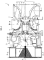
- Fig. 1 is a configuration view of a turbocharger 1 according to the present embodiment.
- the turbocharger 1 includes a turbine 2 which converts energy of an exhaust gas E of an engine into a rotation and a compressor 11 which is driven by the turbine 2.
- the compressor 11 compresses suctioned air W to generate compressed air PW and forcibly feeds the compressed air PW to the engine.
- the turbine 2 is configured of a turbine body 3, and a turbine casing 4 which covers the turbine body 3 from the outer peripheral side and includes an inlet passage 5 and an outlet passage 6 of the exhaust gas E.
- the turbine body 3 includes stator vanes 7 which are attached to the turbine casing 4 and rotor vanes 8 which are attached to a disk 9 which rotates about an axis P.
- the stator vanes 7 are provided to protrude from the turbine casing 4 to the inside in the radial direction of the axis P on a connection portion between the inlet passage 5 and the outlet passage 6, and a plurality of stator vanes 7 are disposed at intervals in a peripheral direction of the axis P.
- the rotor vanes 8 are provided to protrude from an outer peripheral surface of the disk 9 toward the outside in the radial direction and are disposed between the stator vanes 7 at predetermined intervals on a downstream side (a left side on a paper surface of Fig. 1 ) of the stator vane 7.
- the compressor 11 includes a compressor impeller 12 which is a rotating body which is rotatable about the axis P, and a compressor casing 14 which covers the compressor impeller 12 from the outer periphery.
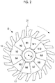
- the compressor impeller 12 is a centrifugal impeller which includes a plurality of vanes 13. As shown in Fig. 2 , the vanes 13 are provided at predetermined intervals in the peripheral direction of the axis P, and for example, 11 vanes 13 are provided.
- the compressor casing 14 includes an air inlet 15 through which the air W is suctioned and an outlet scroll 16 which discharges the compressed air PW compressed by the compressor impeller 12.
- compressor impeller 12 and the disk 9 are fitted to a rotor 17 which rotates about the axis P and integrally rotate about the axis P with each other.
- the rotor 17 is rotatably supported about the axis P by two radial bearings 18 and one thrust bearing 19.
- a gap sensor 21 is provided in the compressor casing 14.
- the gap sensor 21 is provided in the compressor casing 14 at a position facing the vanes 13 of the compressor impeller 12 and measures a distance to a shroud side tip of the vanes 13.
- the gap sensor 21 is a non-contact displacement meter which uses an eddy current effect.
- only one gap sensor 21 is provided in the compressor casing 14, and the gap sensor 21 is positioned at the same position as the inner peripheral surface of the compressor casing 14 (refer to Fig. 6 ).
- the displacement meter is configured of a coil which generates a high frequency magnetic flux, and detects a change of an eddy current generated on the surface of the vane 13 which is a measurement target as a change of impedance of the coil by a high frequency magnetic flux generated from the coil. That is, the change of the distance according to the passage of the vane 13 is detected by the change of the impedance of the coil, and the maximum output is obtained when the vane 13 is closest.
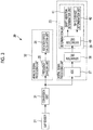
- Fig. 3 is a block diagram showing an electrical configuration of a state observation device 30 according to the present embodiment.
- the state observation device 30 includes the above-described gap sensor 21, a conversion unit 31, an analog signal processing unit 32, and a digital signal processing unit 33. In addition, the state observation device 30 acquires three values, that is, a rotation speed of the compressor impeller 12, a vibration of the compressor impeller 12, and a clearance between the compressor impeller 12 and the compressor casing 14 based on the detection signal of the gap sensor 21, and determines the state of the compressor impeller 12.
- a horizontal direction indicates time
- a vertical direction indicates amplitude
- the gap sensor 21 when the gap sensor 21 faces each vane 13, the gap sensor 21 outputs a larger detection signal as a distance between the gap sensor 21 and the compressor impeller 12 decreases. That is, the detection signal which is periodically output from the gap sensor 21 has a waveform (solid line in Fig. 4 ) which has large amplitude when each vane 13 and the gap sensor 21 face each other and small amplitude at a position at which each vane 13 and the gap sensor 21 are separated from each other, specifically, at an intermediate point between adjacent vanes 13.
- the detection signal indicated by the solid in Fig. 4 is output from the gap sensor 21 to the conversion unit 31.
- the conversion unit 31 includes an amplifier circuit which uses a transistor or the like, amplifies weak detection signals from the gap sensor 21, and outputs the amplified detection signals to the analog signal processing unit 32 and the digital signal processing unit 33.
- the analog signal processing unit 32 includes a frequency division unit 35 and a rotation speed calculation unit 36.
- the detection signal (analog signal) of the gap sensor 21 amplified by the conversion unit 31 is input to the frequency division unit 35, and the frequency division unit 35 divides the detection signal by a predetermined number of times (in the present embodiment, 11 times which is the same as the number of vanes 13) and outputs a rotation speed signal synchronized with the rotation speed of the compressor impeller 12.
- the rotation speed calculation unit 36 counts the number of the rotation speed signals from the frequency division unit 35 so as to calculate the rotation speed of the compressor impeller 12.
- the digital signal processing unit 33 includes an analog-digital convertor (hereinafter, referred to as "ADC") 37, a separation unit 38, and a determination unit 39.
- ADC analog-digital convertor
- the ADC 37 converts the detection signal output from the gap sensor 21 from an analog signal to a digital signal at a predetermined sampling period.
- a predetermined sampling period For example, in Fig. 4 , broken lines indicate sampling intervals, and black dots on an analog waveform indicate detection signals sampled by the ADC 37.
- the separation unit 38 separates the detection signal digitalized by the ADC 37 into a vane detection signal considered to be for detection of the vane 13 and a non-vane detection signal considered not to be for detection of the vane 13.
- the non-vane detection signal is a detection signal which is generated by detecting the rotor 17 or the root of the vane 13 instead of the vane 13.
- a threshold value A shown Fig. 4 is for separating the vane detection signal and the non-vane detection signal, and the detection signal equal to or more than the threshold value A is separated as the vane detection signal and the detection signal less than the threshold value A is separated as the non-vane detection signal by the separation unit 38.
- the determination unit 39 extracting a vane detection signal considered to be for a peak (hereinafter, referred to as a "vane peak") of the vane 13 by relatively comparing the vane detection signal with vane detection signals with respect to other vanes 13 and the non-vane detection signal and determines the state of the compressor impeller 12 on the basis of the extracted vane detection signal.
- a vane peak a peak of the vane 13
- the determination unit 39 includes an extraction unit 40 which performs the extraction, a shaft vibration determination unit 41, and a tip clearance determination unit 42.
- the shaft vibration determination unit 41 determines the vibration state of the compressor impeller 12.
- the tip clearance determination unit 42 determines a state of a clearance (refer to Fig. 4 ) between the maximum value of the vane peak of the compressor impeller 12 and an inner peripheral surface of the compressor casing 14.
- the separation unit 38 and the determination unit 39 included in the digital signal processing unit 33 are configured of a Central Processing Unit (CPU), a Random Access Memory (RAM), a Read Only Memory (ROM), a computer readable storage medium, or the like.
- CPU Central Processing Unit
- RAM Random Access Memory
- ROM Read Only Memory
- a series of processing of realizing various functions is stored in a storage medium or the like in the form of a program, the CPU causes the RAM or the like to read out the program to perform information processing/calculation, and the various functions are realized.
- the program may be installed in a ROM or other storage mediums in advance, may be provided in a state of being stored in a computer readable storage medium, or may be distributed via wired or wireless communication means.
- the computer readable storage medium is a magnetic disk, a magneto-optical disk, a CD-ROM, a DVD-ROM, a semiconductor memory, or the like.
- the compressor impeller 12 rotates at a high speed such as 3,000 rpm. Accordingly, in order to accurately detect the distance between the compressor impeller 12 and the compressor casing 14, preferably, the ADC digitizes the detection signal at high-speed sampling.
- the high-speed sampling is a sampling period at which a peak of the vane can be clearly determined by performing sampling on one vane 13 three times or more, for example.
- the ADC having high performance is required, or the like, which increases a cost.
- the detection signal is digitized for a non-high speed sampling period, for example, for a sampling period (hereinafter, referred to as "low-speed sampling") at which one vane 13 can be detected only once or twice, and accordingly, the ADC having high performance is not required.
- the sampling period by the ADC 37 according to the present embodiment is determined on the basis of the time interval at which one vane 13 passes through a position facing the gap sensor 21.
- Expressions (1) and (2) are calculation expressions with respect to a peripheral speed V (m/s) of a tip portion of the vane 13, D is an outer peripheral diameter (m) of the compressor impeller 12 corresponding to an installation position of the gap sensor 21, ⁇ is an angular velocity (rad/s), and N is a rotation speed (rpm) of the compressor impeller 12. In addition, ⁇ is converted like Expression (2) using the rotation speed N (rpm) of the compressor impeller 12.
- Expression (3) is a calculation expression with respect to a frequency F (Hz, hereinafter, referred to as an "inter-vane pass frequency") at which one vane 13 passes through the gap sensor 21 and n is the number of vanes 13.
- Fs is a sampling frequency (Hz), and in the present embodiment, for example, as shown in Expression (4), Fs is 10 times the inter-vane pass frequency F.
- the diameter D is 35 mm
- the number n of the vanes 13 is 11
- the rotation speed N is 28,000 rpm
- the peripheral speed V of the tip portion is 51.3 m/s
- the inter-vane pass frequency F is 5,100 Hz
- the sampling frequency Fs is 51 kHz. Accordingly, it is possible to sample the vane peak by setting the sampling frequency of ADC 37 to 50 kHz.
- Fig. 5 shows an example of the low-speed sampling.
- Black dots on a waveform shown in Fig. 5 indicate examples of the detection signals sampled by the ADC 37 according to the present embodiment.
- 10 detection signals (v1 to v10) can be sampled by the low-speed sampling with respect to the waveform showing each vane 13 and its surroundings.
- the detection signals two (v2 and v3) exceed the threshold value A and are vane detection signals indicating the vane 13.
- the detection signals v1 and v4 to v9 are less than the threshold value A, the detection signals v1 and v4 to v9 are non-vane detection signals.
- the detection signal is digitized by the low-speed sampling, the digitized vane detection signal does not necessarily indicate the vane peak, and a detection signal indicating a vane position deviated from the vane peak is likely to be digitized.
- the detection signal indicating the vane peak it is preferable to sample the detection signal indicating the vane peak.
- the detection signal in which the center (also referred to as an abdominal) of the vane 13 is detected is likely to be sampled.
- the extraction unit 40 included in the determination unit 39 compares each vane detection signal with vane detection signals corresponding to other vanes 13 and the non-vane detection signal, and extracts a vane detection signal (hereinafter, referred to as a "vane peak detection signal") considered to be for a vane peak.
- a difference between the vane detection signal and the non-vane detection signal is calculated for each vane detection signal as a height (hereinafter, referred to as a "vane height") of the vane 13, and the vane peak detection signal is extracted on the basis of the vane height indicated by each vane detection signal.
- vane height a height of the vane 13
- the vane peak detection signal is extracted on the basis of the vane height indicated by each vane detection signal.
- a calculation method of the vane height there is a method of setting a difference between the lowest value of the non-vane detection signal and each vane detection signal to the vane height of the vane detection signal or a method of setting a difference between an average value of the non-vane detection signals and each vane detection signal to the vane height of each vane detection signal.
- the extraction unit 40 weights the vane detection signal when extracting the vane peak detection signal. Specifically, less weighting is applied to the vane detection signal as a deviation amount from the vane detection signal indicating the highest vane height increases.
- the extraction unit 40 obtains the number of times for each value (vane height) indicated by the vane detection signal and for each value indicated by the non-vane detection signal, which are performed by a plurality of times of sampling.
- the extraction unit 40 determines a weighting factor such that the highest value of the vane detection signal becomes the greatest weight and the lowest value of the vane detection signal becomes the smallest weight, on the basis of the number of times.
- the vane detection signals corresponding to the value of the maximum number of times and the value larger than the maximum number of times indicate the vane peak. Accordingly, as a vane detection signal is smaller than the value of the maximum number of times, a possibility that the vane detection signal does not indicate the vane peak is higher. In order to clarifying this relationship, weighting is applied to the vane detection signal, and extraction of the vane peak detection signal is easily performed.
- the weighting factor is determined such that the highest value of the vane detection signal becomes maximum and the lowest value of the vane detection signal becomes minimum.
- the weighting factor is determined such that a difference between the weight corresponding to the value of the maximum number of times and the weight corresponding to the highest value decreases and a difference between the weight corresponding to the value of the maximum number of times and the weight corresponding to the lowest value increases.
- the extraction unit 40 does not consider the vane detection signal in which the value to which the weighting factor is multiplied is equal to or less than a predetermined threshold value as the vane peak detection signal, and extracts the vane detection signal exceeding the threshold value as the vane peak detection signal.
- the vane detection signal with respect to the vane 13 of N1 is a detection signal which is considered to not be detection for the vane peak.
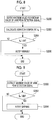
- Fig. 7 is a flowchart showing a flow of impeller state determination processing according to the present embodiment performed by the digital signal processing unit 33.
- Step 100 the detection signal output from the gap sensor 21 is converted from an analog signal into a digital signal at low-speed sampling by the ADC 37.
- Step 102 a predetermined number of the detection signals required for performing a state determination of the compressor impeller 12 are subjected to low-speed sampling, and the sampled detection signals are stored in the store means.
- the predetermined number is a number corresponding to one rotation of the compressor impeller 12, and in the present embodiment, is 11.
- Step 104 whether or not the predetermined number of detection signals is sampled is determined, and in a case of an affirmative determination, the process proceeds to Step 106. Meanwhile, in a case of a negative determination, the process returns to Step 100, and Steps 100 and 102 are repeated until the predetermined number of detection signals is sampled.
- Step 106 the separation unit 38 separates a vane detection signal v n from the detection signal subjected to low-speed sampling.
- Step S108 based on the value (vane height) indicated by the vane detection signal v n and the number of times for each vane height indicated by the vane detection signal v n , the weighting factor w n for each vane detection signal v n is determined.
- Step 110 the vane detection signal v n is multiplied by the corresponding weight factor w n .
- Step S112 the vane peak detection signal is extracted from the vane detection signal v n multiplied by the weighting factor w n .
- Steps 108 to 112 is performed by the extraction unit 40.
- Step 114 based on the extracted vane peak detection signal, the shaft vibration determination unit 41 performs shaft vibration determination processing, the tip clearance determination unit 42 performs the tip clearance determination processing, and the state of the compressor impeller 12 is determined.
- Step 100 the processing returns to Step 100, and the impeller state determination processing is performed on the basis of the detection signal which is newly subjected to low-speed sampling.
- Fig. 8 is a flowchart showing a flow of the shaft vibration determination processing according to the present embodiment performed by the shaft vibration determination unit 41.
- Step 200 the maximum value v max and the minimum value v min of the vane peak detection signal are derived.
- Step 202 a difference between the maximum value v max and the minimum value v min of the vane peak detection signal is calculated as a vibration component A n .
- Step 204 the vibration component A n and a predetermined reference vibration component AA are compared with each other, whether or not the vibration component A n exceeds the reference vibration component AA is determined, and in a case of the affirmative determination, the process proceeds to Step 206. Meanwhile, in a case where the vibration component A n does not exceed the reference vibration component AA, the shaft vibration determination processing ends, and the process returns to Step 100.
- the reference vibration component AA is a threshold value for detecting abnormal vibrations of the rotary machine, and if the vibration component A n reaches the reference vibration component AA, for example, notification of alarm or automatic stop of the rotary machine is performed. That is, the reference vibration component AA is an alarm setting value or an automatic stop setting value of the rotary machine.
- a plurality of reference vibration components AA different from each other may be set, and every time the vibration component An increases and reaches the plurality of reference vibration components AA, notification of alarm or automatic stop of the rotary machine may be performed in stages.
- Step 206 the shaft vibration is excessive, and notification of warning is performed. Accordingly, a worker stops an apparatus including the turbocharger 1 or repairs the turbocharger 1 when the turbocharger 1 is inspected next time.
- Fig. 9 is flowchart showing a flow of the tip clearance determination processing according to the present embodiment performed by the tip clearance determination unit 42.
- Step 300 the maximum value v max of the vane peak detection signal is derived.
- the maximum value v max is a clearance B n corresponding to the tip clearance.
- Step 302 the clearance B n and a predetermined reference clearance BB are compared with each other, whether or not the clearance B n exceeds the reference clearance BB is determined, and in a case of the affirmative determination, the process proceeds to Step 304. Meanwhile, in a case where the clearance B n does not exceed the reference clearance BB, the tip clearance determination processing ends, and the process returns to Step 100.
- the reference clearance BB is a threshold value for detecting the vane 13 approaching the compressor casing 14, and if the clearance B n reaches the reference clearance BB, for example, notification of alarm or automatic stop of the rotary machine is performed. That is, the reference clearance BB is an alarm setting value or an automatic stop setting value of the rotary machine.
- a plurality of reference clearances BB different from each other may be set, and every time the clearance B n increases and reaches the plurality of reference clearances BB, notification of alarm or automatic stop of the rotary machine may be performed in stages.
- Step 304 notification of warning is performed in a case where there is a possibility that the vane 13 comes into contact with the compressor casing 14. Accordingly, a worker stops an apparatus including the turbocharger 1 or repairs the turbocharger 1 when the turbocharger 1 is inspected next time.
- the state observation device 30 observes the rotation speed of the compressor impeller 12 using the gap sensor 21 which detects the distance between the compressor impeller 12 and the gap sensor 21.
- the detection signal is digitized by the gap sensor 21 at the low-speed sampling period performed by the ADC 37, and the digitized detection signal is separated into the vane detection signal considered to be for detection of the vane 13 of the compressor impeller 12 and the non-vane detection signal considered not to be for detection of the vane 13 by the separation unit 38.
- the vane detection signal and the vane detection signals corresponding to other vanes 13 and the non-vane detection signal are compared with each other by the determination unit 39, the vane peak detection signal considered to be for the vane peak is extracted, and the shaft vibration and the tip clearance which are states of the compressor impeller 12 are determined on the basis of the extracted vane peak detection signal.
- the vane detection signals and the non-vane detection signals of the plurality of vanes 13 are relatively compared with each other, the vane peak detection signal considered to be for the vane peak is extracted, and the state of the compressor impeller 12 is determined. Accordingly, since it is enough for the detection signal indicating the distance to the vane 13 to be sampled at least once for each vane 13, to the state observation device 30 can observe the state of the turbocharger 1 without performing high-speed sampling.
- the present invention is not limited to this, and an aspect in which a plurality of gap sensors 21 are provided at positions at which the phases are deviated from each other may be adopted.
- the rotary machine according to the present invention is the turbocharger 1
- the present invention is not limited to this, and other rotary machines may be adopted as long as the rotary machine includes the impeller.
Landscapes
- Engineering & Computer Science (AREA)
- Mechanical Engineering (AREA)
- General Engineering & Computer Science (AREA)
- Physics & Mathematics (AREA)
- General Physics & Mathematics (AREA)
- Combustion & Propulsion (AREA)
- Chemical & Material Sciences (AREA)
- Acoustics & Sound (AREA)
- Structures Of Non-Positive Displacement Pumps (AREA)
- Testing Of Devices, Machine Parts, Or Other Structures Thereof (AREA)
- Measurement Of Mechanical Vibrations Or Ultrasonic Waves (AREA)
- Measurement Of Length, Angles, Or The Like Using Electric Or Magnetic Means (AREA)
- Control Of Positive-Displacement Air Blowers (AREA)
Description
- The present invention relates to a rotary machine state observation device, a rotary machine, and a rotary machine state observation method.
- In a rotary machine such as a turbo machine, an impeller which integrally rotates with a rotor is provided. The impeller includes a plurality of vanes and is accommodated in a casing.
- In addition, a predetermined amount of clearance is required between the vanes and the casing to reliably prevent contact between the vanes of the impeller and the casing.
- However, during operation of the rotary machine, synchronous vibrations due to a rotation frequency of the rotor, backlash of a bearing portion which supports the rotor, non-synchronous vibrations due to turbulence or the like of a flowing fluid, or the like may occur. Accordingly, the vanes oscillate beyond the clearance due to the vibrations and the vanes are likely to come into contact with the casing.
- In view of the above, a state observation device disclosed in
JP 2013-224847 -
US 2009/0256556 A1 andUS 2013/0197747 A1 disclose a measuring arrangement for detecting a rotary momentum of an engine rotor. - According to
US 2009/0256556 A1 a sensor is provided and at least one material measure is fashioned on the rotor that can be periodically detected by the sensor due to its rotational movement. The material measure is formed by at least one modified vane element that is truncated in the area of the vane tip, wherein the sensor outputs an identical measurement signal in each case when the vane element travels past. - According to
US 2013/0197747 A1 an acquisition means is provided for acquiring the revolutions per minute of the engine based on the deflection signal representative of the deflections of the blades of the impeller at corresponding revolutions per minute. - In the state observation device disclosed in
JP 2013-224847 - In order to realize high-speed sampling, an analog-digital converter which can perform high-speed sampling with high frequency characteristics is required, which generates an increase in a cost of the entire device.
- The present invention is made in consideration of the above-described circumstances, and an object thereof is to provide a rotary machine state observation device, a rotary machine, and a rotary machine state observation method in which a state of the rotary machine can be observed without performing high-speed sampling.
- In order to achieve the object, a rotary machine state observation device according to
claim 1, a rotary machine according to claim 4, and a rotary machine state observation method according toclaim 5 are provided. Preferred embodiments follow form the other claims. - According to a first aspect of the present invention, there is provided a rotary machine state observation device including inter alia: detection means for detecting a distance between an impeller of a rotary machine and the detection means, the detection means being provided at an interval in a radial direction between the impeller and the detection means; conversion means for digitizing a detection signal detected by the detection means at a predetermined sampling period; separation means for separating a detection signal digitized by the conversion means into a vane detection signal considered to be for detection of a vane of the impeller and a non-vane detection signal considered not to be for detection of the vane; and determination means for extracting a vane detection signal considered to be for a peak of the vane by comparing the vane detection signal with vane detection signals corresponding to other vanes and the non-vane detection signal and determining a state of the impeller on the basis of the extracted vane detection signal.
- According to the present configuration, the detection means is provided at an interval in the radial direction between the impeller of the rotary machine and the detection means, and the detection signal detected by the detection means is digitized by the conversion means at a predetermined sampling period.
- Here, for example, an impeller of a turbo machine or the like rotates at a high speed such as 3,000 rpm. Accordingly, in order to accurately detect the distance between the impeller and the detection means, preferably, the conversion means digitizes the detection signal by high-speed sampling. Here, the high-speed sampling is a sampling period at which a peak of the vane can be clearly determined by performing sampling on one vane three times or more, for example. However, in order to perform the high-speed sampling, conversion means having high performance is required, or the like, which increases a cost.
- Meanwhile, the detection signal is digitized for a non-high speed sampling period, for example, for a sampling period at which one vane can be detected only once or twice, and accordingly, the conversion means having high performance is not required.
- Therefore, in the present configuration, the separation means separates the detection signal digitized by the conversion means into a vane detection signal considered to be for detection of the vane of the impeller and a non-vane detection signal considered not to be for detection of the vane. A method of separating the detection signal using a predetermined threshold value is used.
- However, if the detection signal is digitized at a sampling period which is performed on one vane approximately once or twice, the digitized vane detection signal does not necessarily indicate the peak of the vane, and a detection signal indicating a vane position deviated from the peak is likely to be digitized. In this way, in the vane detection signal digitized at the non-high speed sampling period, a detection result with respect to the peak of the vane and a detection result of the vane position deviated from the peak are mixed.
- Accordingly, the determination means extracts a vane detection signal considered to be for a peak of the vane by comparing the vane detection signal with vane detection signals corresponding to other vanes and the non-vane detection signal. For example, as a comparison method, there is a method of calculating a height of the vane from a difference between each vane detection signal and the non-vane detection signal and extracting the vane detection signal considered to be for the peak of the vane on the basis of the height of the vane indicated by each vane detection signal.
- Moreover, the determination means determines the state of the impeller on the basis of the extracted vane detection signal considered to be for the peak of the vane.
- In this way, in the present configuration, by relatively comparing the vane detection signals of the plurality of vanes and the non-vane detection signals, the vane detection signal considered to be for the peak of the vane is extracted and the state of the impeller is determined. Accordingly, since it is enough for a detection signal indicating a distance to the vane to be sampled at least once for each vane, in the present configuration, it is possible to observe the state of the rotary machine without performing high-speed sampling.
- In the first aspect, the determination means may less weight the vane detection signal as a deviation amount from the vane detection signal indicating the highest value increases.
- In the present configuration, with respect to the determination of the state of the impeller, it is possible to decrease influences of the vane detection signal having a large deviation amount from the peak.
- In the first aspect, the predetermined sampling period may be determined on the basis of a time interval at which one vane passes through a position facing the detection means.
- In the present configuration, as a non-high speed sampling period, it is possible to determine an appropriate sampling period.
- According to a second aspect of the present invention, there is provided a rotary machine, including: an impeller; a casing which accommodates the impeller; and the above-described state observation device.
- According to a third aspect of the present invention, there is provided a rotary machine state observation method, including inter alia: a first step of detecting a distance between an impeller of a rotary machine and detection means by the detection means which is provided at an interval in a radial direction between the impeller and the detection means; a second step of digitizing a detection signal detected by the detection means at a predetermined sampling period; a third step of separating the digitized detection signal into a vane detection signal considered to be for detection of a vane of the impeller and a non-vane detection signal considered not to be for detection of the vane; and a fourth step of extracting a vane detection signal considered to be for a peak of the vane by comparing the vane detection signal with vane detection signals corresponding to other vanes and the non-vane detection signal and determining a state of the impeller on the basis of the extracted vane detection signal.
- According to the present invention, it is possible to observe the state of the rotary machine without performing high-speed sampling.
-
-
Fig. 1 is a configuration view of a turbocharger according an embodiment of the present invention. -
Fig. 2 is a configuration view of a vane according to the embodiment of the present invention. -
Fig. 3 is a block diagram showing an electrical configuration of a state observation device according to the embodiment of the present invention. -
Fig. 4 is a schematic diagram showing a detection signal of a gap sensor according to the embodiment of the present invention. -
Fig. 5 is a schematic diagram showing an example of low-speed sampling according to the embodiment of the present invention. -
Fig. 6 is a schematic diagram showing an example of a vane detection position by the low-speed sampling according to the embodiment of the present invention. -
Fig. 7 is a flowchart showing a flow of impeller state determination processing according to the embodiment of the present invention. -
Fig. 8 is a flowchart showing a flow of shaft vibration determination processing according to the embodiment of the present invention. -
Fig. 9 is flowchart showing a flow of tip clearance determination processing according to the embodiment of the present invention. - Hereinafter, embodiments of a rotary machine state observation device, a rotary machine, and a rotary machine state observation method according to the present invention will be described with reference to the drawings.
-
Fig. 1 is a configuration view of aturbocharger 1 according to the present embodiment. - As shown in
Fig. 1 , theturbocharger 1 includes aturbine 2 which converts energy of an exhaust gas E of an engine into a rotation and acompressor 11 which is driven by theturbine 2. - The
compressor 11 compresses suctioned air W to generate compressed air PW and forcibly feeds the compressed air PW to the engine. - The
turbine 2 is configured of a turbine body 3, and a turbine casing 4 which covers the turbine body 3 from the outer peripheral side and includes aninlet passage 5 and anoutlet passage 6 of the exhaust gas E. - The turbine body 3 includes stator vanes 7 which are attached to the turbine casing 4 and
rotor vanes 8 which are attached to adisk 9 which rotates about an axis P. - The stator vanes 7 are provided to protrude from the turbine casing 4 to the inside in the radial direction of the axis P on a connection portion between the
inlet passage 5 and theoutlet passage 6, and a plurality of stator vanes 7 are disposed at intervals in a peripheral direction of the axis P. - The
rotor vanes 8 are provided to protrude from an outer peripheral surface of thedisk 9 toward the outside in the radial direction and are disposed between the stator vanes 7 at predetermined intervals on a downstream side (a left side on a paper surface ofFig. 1 ) of the stator vane 7. - The
compressor 11 includes acompressor impeller 12 which is a rotating body which is rotatable about the axis P, and acompressor casing 14 which covers thecompressor impeller 12 from the outer periphery. - The
compressor impeller 12 is a centrifugal impeller which includes a plurality ofvanes 13. As shown inFig. 2 , thevanes 13 are provided at predetermined intervals in the peripheral direction of the axis P, and for example, 11vanes 13 are provided. - The
compressor casing 14 includes anair inlet 15 through which the air W is suctioned and anoutlet scroll 16 which discharges the compressed air PW compressed by thecompressor impeller 12. - In addition, the
compressor impeller 12 and thedisk 9 are fitted to arotor 17 which rotates about the axis P and integrally rotate about the axis P with each other. In addition, therotor 17 is rotatably supported about the axis P by tworadial bearings 18 and onethrust bearing 19. - In addition, as shown in
Fig. 2 , agap sensor 21 is provided in thecompressor casing 14. Thegap sensor 21 is provided in thecompressor casing 14 at a position facing thevanes 13 of thecompressor impeller 12 and measures a distance to a shroud side tip of thevanes 13. - For example, the
gap sensor 21 according to the present embodiment is a non-contact displacement meter which uses an eddy current effect. In addition, for example, only onegap sensor 21 is provided in thecompressor casing 14, and thegap sensor 21 is positioned at the same position as the inner peripheral surface of the compressor casing 14 (refer toFig. 6 ). - Here, an operation principle of the displacement meter which uses the eddy current effect will be described. The displacement meter is configured of a coil which generates a high frequency magnetic flux, and detects a change of an eddy current generated on the surface of the
vane 13 which is a measurement target as a change of impedance of the coil by a high frequency magnetic flux generated from the coil. That is, the change of the distance according to the passage of thevane 13 is detected by the change of the impedance of the coil, and the maximum output is obtained when thevane 13 is closest. -
Fig. 3 is a block diagram showing an electrical configuration of astate observation device 30 according to the present embodiment. - The
state observation device 30 includes the above-describedgap sensor 21, aconversion unit 31, an analogsignal processing unit 32, and a digitalsignal processing unit 33. In addition, thestate observation device 30 acquires three values, that is, a rotation speed of thecompressor impeller 12, a vibration of thecompressor impeller 12, and a clearance between thecompressor impeller 12 and thecompressor casing 14 based on the detection signal of thegap sensor 21, and determines the state of thecompressor impeller 12. - Here, the detection signal (analog signal) output from the
gap sensor 21 will be described with reference toFig. 4 . InFig. 4 , a horizontal direction indicates time, and a vertical direction indicates amplitude. - As shown in
Fig. 4 , when thegap sensor 21 faces eachvane 13, thegap sensor 21 outputs a larger detection signal as a distance between thegap sensor 21 and thecompressor impeller 12 decreases. That is, the detection signal which is periodically output from thegap sensor 21 has a waveform (solid line inFig. 4 ) which has large amplitude when eachvane 13 and thegap sensor 21 face each other and small amplitude at a position at which eachvane 13 and thegap sensor 21 are separated from each other, specifically, at an intermediate point betweenadjacent vanes 13. - In addition, every time the
compressor impeller 12 rotates once, peaks having the number of times (in the present embodiment, 11 times, and N1 to N11) corresponding to the number ofvanes 13 are output from thegap sensor 21. - The detection signal indicated by the solid in
Fig. 4 is output from thegap sensor 21 to theconversion unit 31. - For example, the
conversion unit 31 includes an amplifier circuit which uses a transistor or the like, amplifies weak detection signals from thegap sensor 21, and outputs the amplified detection signals to the analogsignal processing unit 32 and the digitalsignal processing unit 33. - The analog
signal processing unit 32 includes afrequency division unit 35 and a rotationspeed calculation unit 36. - The detection signal (analog signal) of the
gap sensor 21 amplified by theconversion unit 31 is input to thefrequency division unit 35, and thefrequency division unit 35 divides the detection signal by a predetermined number of times (in the present embodiment, 11 times which is the same as the number of vanes 13) and outputs a rotation speed signal synchronized with the rotation speed of thecompressor impeller 12. - The rotation
speed calculation unit 36 counts the number of the rotation speed signals from thefrequency division unit 35 so as to calculate the rotation speed of thecompressor impeller 12. - The digital
signal processing unit 33 includes an analog-digital convertor (hereinafter, referred to as "ADC") 37, aseparation unit 38, and adetermination unit 39. - The
ADC 37 converts the detection signal output from thegap sensor 21 from an analog signal to a digital signal at a predetermined sampling period. For example, inFig. 4 , broken lines indicate sampling intervals, and black dots on an analog waveform indicate detection signals sampled by theADC 37. - The
separation unit 38 separates the detection signal digitalized by theADC 37 into a vane detection signal considered to be for detection of thevane 13 and a non-vane detection signal considered not to be for detection of thevane 13. In addition, the non-vane detection signal is a detection signal which is generated by detecting therotor 17 or the root of thevane 13 instead of thevane 13. - A threshold value A shown
Fig. 4 is for separating the vane detection signal and the non-vane detection signal, and the detection signal equal to or more than the threshold value A is separated as the vane detection signal and the detection signal less than the threshold value A is separated as the non-vane detection signal by theseparation unit 38. - The
determination unit 39 extracting a vane detection signal considered to be for a peak (hereinafter, referred to as a "vane peak") of thevane 13 by relatively comparing the vane detection signal with vane detection signals with respect toother vanes 13 and the non-vane detection signal and determines the state of thecompressor impeller 12 on the basis of the extracted vane detection signal. - The
determination unit 39 includes anextraction unit 40 which performs the extraction, a shaftvibration determination unit 41, and a tipclearance determination unit 42. - The shaft
vibration determination unit 41 determines the vibration state of thecompressor impeller 12. - The tip
clearance determination unit 42 determines a state of a clearance (refer toFig. 4 ) between the maximum value of the vane peak of thecompressor impeller 12 and an inner peripheral surface of thecompressor casing 14. - In addition, for example, the
separation unit 38 and thedetermination unit 39 included in the digitalsignal processing unit 33 are configured of a Central Processing Unit (CPU), a Random Access Memory (RAM), a Read Only Memory (ROM), a computer readable storage medium, or the like. In addition, for example, a series of processing of realizing various functions is stored in a storage medium or the like in the form of a program, the CPU causes the RAM or the like to read out the program to perform information processing/calculation, and the various functions are realized. In addition, the program may be installed in a ROM or other storage mediums in advance, may be provided in a state of being stored in a computer readable storage medium, or may be distributed via wired or wireless communication means. The computer readable storage medium is a magnetic disk, a magneto-optical disk, a CD-ROM, a DVD-ROM, a semiconductor memory, or the like. - Here, for example, the
compressor impeller 12 rotates at a high speed such as 3,000 rpm. Accordingly, in order to accurately detect the distance between thecompressor impeller 12 and thecompressor casing 14, preferably, the ADC digitizes the detection signal at high-speed sampling. Here, the high-speed sampling is a sampling period at which a peak of the vane can be clearly determined by performing sampling on onevane 13 three times or more, for example. However, in order to perform the high-speed sampling, the ADC having high performance is required, or the like, which increases a cost. - Accordingly, in the
state observation device 30 according to the present embodiment, the detection signal is digitized for a non-high speed sampling period, for example, for a sampling period (hereinafter, referred to as "low-speed sampling") at which onevane 13 can be detected only once or twice, and accordingly, the ADC having high performance is not required. - The sampling period by the
ADC 37 according to the present embodiment is determined on the basis of the time interval at which onevane 13 passes through a position facing thegap sensor 21. - The following Expressions (1) to (4) are examples of calculation expressions for determining the low-sampling period by the
ADC 37 according to the present embodiment.
[Expression 1]


- Expressions (1) and (2) are calculation expressions with respect to a peripheral speed V (m/s) of a tip portion of the
vane 13, D is an outer peripheral diameter (m) of thecompressor impeller 12 corresponding to an installation position of thegap sensor 21, ω is an angular velocity (rad/s), and N is a rotation speed (rpm) of thecompressor impeller 12. In addition, ω is converted like Expression (2) using the rotation speed N (rpm) of thecompressor impeller 12. - In addition, Expression (3) is a calculation expression with respect to a frequency F (Hz, hereinafter, referred to as an "inter-vane pass frequency") at which one
vane 13 passes through thegap sensor 21 and n is the number ofvanes 13. - In addition, Fs is a sampling frequency (Hz), and in the present embodiment, for example, as shown in Expression (4), Fs is 10 times the inter-vane pass frequency F.
- Here, for example, in a case where the diameter D is 35 mm, the number n of the
vanes 13 is 11, and the rotation speed N is 28,000 rpm, the peripheral speed V of the tip portion is 51.3 m/s, the inter-vane pass frequency F is 5,100 Hz, and the sampling frequency Fs is 51 kHz. Accordingly, it is possible to sample the vane peak by setting the sampling frequency ofADC 37 to 50 kHz. -
Fig. 5 shows an example of the low-speed sampling. Black dots on a waveform shown inFig. 5 indicate examples of the detection signals sampled by theADC 37 according to the present embodiment. As shown inFig. 5 , 10 detection signals (v1 to v10) can be sampled by the low-speed sampling with respect to the waveform showing eachvane 13 and its surroundings. Among the detection signals, two (v2 and v3) exceed the threshold value A and are vane detection signals indicating thevane 13. In addition, since the detection signals v1 and v4 to v9 are less than the threshold value A, the detection signals v1 and v4 to v9 are non-vane detection signals. - However, if the detection signal is digitized by the low-speed sampling, the digitized vane detection signal does not necessarily indicate the vane peak, and a detection signal indicating a vane position deviated from the vane peak is likely to be digitized.
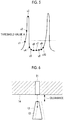
- That is, it is preferable to sample the detection signal indicating the vane peak. However, in the low-speed sampling, like the detection with respect to the
vane 13 shown by a broken line inFig. 6 , the detection signal in which the center (also referred to as an abdominal) of thevane 13 is detected is likely to be sampled. - In this way, if the state of the
compressor impeller 12 is determined in a state where the vane detection signal considered not to be for the vane peak is included, the determination is likely to be erroneously performed. - Accordingly, the
extraction unit 40 included in thedetermination unit 39 compares each vane detection signal with vane detection signals corresponding toother vanes 13 and the non-vane detection signal, and extracts a vane detection signal (hereinafter, referred to as a "vane peak detection signal") considered to be for a vane peak. - For example, in a comparison method performed by the
extraction unit 40, a difference between the vane detection signal and the non-vane detection signal is calculated for each vane detection signal as a height (hereinafter, referred to as a "vane height") of thevane 13, and the vane peak detection signal is extracted on the basis of the vane height indicated by each vane detection signal. Meanwhile, since detection frequency with respect to the non-vane detection signal increases, the number of times of the non-vane detection signals is not counted. By not counting the non-vane detection signals, erroneous determination is not performed. - For example, as a calculation method of the vane height, there is a method of setting a difference between the lowest value of the non-vane detection signal and each vane detection signal to the vane height of the vane detection signal or a method of setting a difference between an average value of the non-vane detection signals and each vane detection signal to the vane height of each vane detection signal.
- In addition, the
extraction unit 40 according to the present embodiment weights the vane detection signal when extracting the vane peak detection signal. Specifically, less weighting is applied to the vane detection signal as a deviation amount from the vane detection signal indicating the highest vane height increases. - The weighting will be described with reference to
Fig. 4 . - As shown on the right side of the paper surface in
Fig. 4 , theextraction unit 40 obtains the number of times for each value (vane height) indicated by the vane detection signal and for each value indicated by the non-vane detection signal, which are performed by a plurality of times of sampling. Theextraction unit 40 determines a weighting factor such that the highest value of the vane detection signal becomes the greatest weight and the lowest value of the vane detection signal becomes the smallest weight, on the basis of the number of times. - That is, since the
compressor impeller 12 rotates while being slightly vibrates, even when the vane detection signal detects the vane peak, variations in the size occur (amplitude of the vane peak shown by a broken line inFig. 4 ). Accordingly, there is a case where it is not clear whether the vane detection signal having a small vane height is the detection result of the vane peak or is the detection result of the abdominal of thevane 13. Accordingly, the number of times (frequency) of the value of the vane height is obtained, a weighting factor for each value of the vane detection signal is determined on the basis of the number of times, and the determined weighting factor is multiplied by the value of each vane detection signal. - That is, it is considered that the vane detection signals corresponding to the value of the maximum number of times and the value larger than the maximum number of times indicate the vane peak. Accordingly, as a vane detection signal is smaller than the value of the maximum number of times, a possibility that the vane detection signal does not indicate the vane peak is higher. In order to clarifying this relationship, weighting is applied to the vane detection signal, and extraction of the vane peak detection signal is easily performed.
- Moreover, as described above, the weighting factor is determined such that the highest value of the vane detection signal becomes maximum and the lowest value of the vane detection signal becomes minimum. However, the weighting factor is determined such that a difference between the weight corresponding to the value of the maximum number of times and the weight corresponding to the highest value decreases and a difference between the weight corresponding to the value of the maximum number of times and the weight corresponding to the lowest value increases.
- In addition, for example, the
extraction unit 40 does not consider the vane detection signal in which the value to which the weighting factor is multiplied is equal to or less than a predetermined threshold value as the vane peak detection signal, and extracts the vane detection signal exceeding the threshold value as the vane peak detection signal. - In the example of
Fig. 4 , the vane detection signal with respect to thevane 13 of N1 is a detection signal which is considered to not be detection for the vane peak. -
Fig. 7 is a flowchart showing a flow of impeller state determination processing according to the present embodiment performed by the digitalsignal processing unit 33. - First, in
Step 100, the detection signal output from thegap sensor 21 is converted from an analog signal into a digital signal at low-speed sampling by theADC 37. - Next, in Step 102, a predetermined number of the detection signals required for performing a state determination of the
compressor impeller 12 are subjected to low-speed sampling, and the sampled detection signals are stored in the store means. For example, here, the predetermined number is a number corresponding to one rotation of thecompressor impeller 12, and in the present embodiment, is 11. - Next, in
Step 104, whether or not the predetermined number of detection signals is sampled is determined, and in a case of an affirmative determination, the process proceeds to Step 106. Meanwhile, in a case of a negative determination, the process returns to Step 100, andSteps 100 and 102 are repeated until the predetermined number of detection signals is sampled. - In Step 106, the
separation unit 38 separates a vane detection signal vn from the detection signal subjected to low-speed sampling. - Next, in Step S108, based on the value (vane height) indicated by the vane detection signal vn and the number of times for each vane height indicated by the vane detection signal vn, the weighting factor wn for each vane detection signal vn is determined.
- Next, in
Step 110, the vane detection signal vn is multiplied by the corresponding weight factor wn. - Next, in Step S112, the vane peak detection signal is extracted from the vane detection signal vn multiplied by the weighting factor wn.
- Moreover, the processing of Steps 108 to 112 is performed by the
extraction unit 40. - Next, in Step 114, based on the extracted vane peak detection signal, the shaft
vibration determination unit 41 performs shaft vibration determination processing, the tipclearance determination unit 42 performs the tip clearance determination processing, and the state of thecompressor impeller 12 is determined. - Moreover, after this determination ends, the processing returns to Step 100, and the impeller state determination processing is performed on the basis of the detection signal which is newly subjected to low-speed sampling.
-
Fig. 8 is a flowchart showing a flow of the shaft vibration determination processing according to the present embodiment performed by the shaftvibration determination unit 41. - First, in
Step 200, the maximum value vmax and the minimum value vmin of the vane peak detection signal are derived. - Next, in Step 202, a difference between the maximum value vmax and the minimum value vmin of the vane peak detection signal is calculated as a vibration component An.
- Next, in Step 204, the vibration component An and a predetermined reference vibration component AA are compared with each other, whether or not the vibration component An exceeds the reference vibration component AA is determined, and in a case of the affirmative determination, the process proceeds to Step 206. Meanwhile, in a case where the vibration component An does not exceed the reference vibration component AA, the shaft vibration determination processing ends, and the process returns to Step 100.
- The reference vibration component AA is a threshold value for detecting abnormal vibrations of the rotary machine, and if the vibration component An reaches the reference vibration component AA, for example, notification of alarm or automatic stop of the rotary machine is performed. That is, the reference vibration component AA is an alarm setting value or an automatic stop setting value of the rotary machine. In addition, a plurality of reference vibration components AA different from each other may be set, and every time the vibration component An increases and reaches the plurality of reference vibration components AA, notification of alarm or automatic stop of the rotary machine may be performed in stages.
- In Step 206, the shaft vibration is excessive, and notification of warning is performed. Accordingly, a worker stops an apparatus including the
turbocharger 1 or repairs theturbocharger 1 when theturbocharger 1 is inspected next time. -
Fig. 9 is flowchart showing a flow of the tip clearance determination processing according to the present embodiment performed by the tipclearance determination unit 42. - First, in
Step 300, the maximum value vmax of the vane peak detection signal is derived. The maximum value vmax is a clearance Bn corresponding to the tip clearance. - Next, in Step 302, the clearance Bn and a predetermined reference clearance BB are compared with each other, whether or not the clearance Bn exceeds the reference clearance BB is determined, and in a case of the affirmative determination, the process proceeds to Step 304. Meanwhile, in a case where the clearance Bn does not exceed the reference clearance BB, the tip clearance determination processing ends, and the process returns to Step 100.
- The reference clearance BB is a threshold value for detecting the
vane 13 approaching thecompressor casing 14, and if the clearance Bn reaches the reference clearance BB, for example, notification of alarm or automatic stop of the rotary machine is performed. That is, the reference clearance BB is an alarm setting value or an automatic stop setting value of the rotary machine. In addition, a plurality of reference clearances BB different from each other may be set, and every time the clearance Bn increases and reaches the plurality of reference clearances BB, notification of alarm or automatic stop of the rotary machine may be performed in stages. - In Step 304, notification of warning is performed in a case where there is a possibility that the
vane 13 comes into contact with thecompressor casing 14. Accordingly, a worker stops an apparatus including theturbocharger 1 or repairs theturbocharger 1 when theturbocharger 1 is inspected next time. - As described above, the
state observation device 30 according to the present embodiment observes the rotation speed of thecompressor impeller 12 using thegap sensor 21 which detects the distance between thecompressor impeller 12 and thegap sensor 21. - In addition, in the
state observation device 30, the detection signal is digitized by thegap sensor 21 at the low-speed sampling period performed by theADC 37, and the digitized detection signal is separated into the vane detection signal considered to be for detection of thevane 13 of thecompressor impeller 12 and the non-vane detection signal considered not to be for detection of thevane 13 by theseparation unit 38. In addition, the vane detection signal and the vane detection signals corresponding toother vanes 13 and the non-vane detection signal are compared with each other by thedetermination unit 39, the vane peak detection signal considered to be for the vane peak is extracted, and the shaft vibration and the tip clearance which are states of thecompressor impeller 12 are determined on the basis of the extracted vane peak detection signal. - In this way, in the
state observation device 30 according the present embodiment, the vane detection signals and the non-vane detection signals of the plurality ofvanes 13 are relatively compared with each other, the vane peak detection signal considered to be for the vane peak is extracted, and the state of thecompressor impeller 12 is determined. Accordingly, since it is enough for the detection signal indicating the distance to thevane 13 to be sampled at least once for eachvane 13, to thestate observation device 30 can observe the state of theturbocharger 1 without performing high-speed sampling. - Hereinbefore, the present invention is described with reference the above-described embodiment. However, a technical scope of the present invention is not limited to the range described in the embodiment. Various modifications or improvements can be applied to the embodiment within a scope of the present invention, and the aspects to which the modifications or the improvements are added also are included in the technical scope of the present invention. In addition, the above-described embodiments may be appropriately combined.
- For example, in the above-described embodiment, the aspect in which one
gap sensor 21 is provided in thecompressor casing 14 is described. However, the present invention is not limited to this, and an aspect in which a plurality ofgap sensors 21 are provided at positions at which the phases are deviated from each other may be adopted. - For example, in the above-described embodiment, the aspect in which the rotary machine according to the present invention is the
turbocharger 1 is described. However, the present invention is not limited to this, and other rotary machines may be adopted as long as the rotary machine includes the impeller. - In addition, the flow of each processing described in the above-described embodiment is an example, an unnecessary step may be omitted, a new step may be added, or a processing sequence may be replaced within a scope of the present invention.
-
- 1:
- turbocharger
- 12:
- compressor impeller
- 21:
- gap sensor
- 30:
- state observation device
- 37:
- analog-digital convertor (ADC)
- 38:
- separation unit
- 39:
- determination unit
- 40:
- extraction unit
Claims (5)
- A rotary machine state observation device, comprising:detection means (21) for detecting a distance between an impeller (12) of a rotary machine (2) and the detection means (21), the detection means (21) being provided at an interval in a radial direction between the impeller (12) and the detection means (21);analog-digital conversion means (37) for digitizing a detection signal detected by the detection means (21) at a predetermined sampling period;separation means (38) for separating a detection signal digitized by the analog-digital conversion means (37) into a vane detection signal considered to be for detection of a vane (13) of the impeller (12) and a non-vane detection signal considered not to be for detection of the vane (13); anddetermination means (39) for extracting a vane detection signal considered to be for a peak of the vane (13) by comparing the vane detection signal with vane detection signals corresponding to other vanes and the non-vane detection signal and determining a state of the impeller (12) on the basis of the extracted vane detection signal,wherein the separation means (38) separates a detection signal equal to or more than a threshold value (A) as the vane detection signal, and separates a detection signal less than the threshold value (A) as the non-vane detection signal.
- The rotary machine state observation device according to claim 1,
wherein the determination means (39) is adapted to less weight the vane detection signal as a deviation amount from the vane detection signal indicating the highest value increases. - The rotary machine state observation device according to claim 1 or 2,
wherein the predetermined sampling period is determined on the basis of a time interval at which one vane (13) passes through a position facing the detection means (21). - A rotary machine, comprising:an impeller (12);a casing (14) which accommodates the impeller (12); andthe rotary machine state observation device (30) according to any one of claims 1 to 3.
- A rotary machine state observation method, comprising:a first step of detecting a distance between an impeller (12) of a rotary machine (2) and detection means (21) by the detection means (21) which is provided at an interval in a radial direction between the impeller (12) and the detection means (21);a second step of digitizing a detection signal detected by the detection means (21) at a predetermined sampling period by an analog-digital conversion means (37) ;a third step of separating the digitized detection signal into a vane detection signal considered to be for detection of a vane (13) of the impeller (12) and a non-vane detection signal considered not to be for detection of the vane (13); whereina separation means (38) separates a detection signal equal to or more than a threshold value (A) as the vane detection signal, and separates a detection signal less than the threshold value (A) as the non-vane detection signal; anda fourth step of extracting a vane detection signal considered to be for a peak of the vane (13) by comparing the vane detection signal with vane detection signals corresponding to other vanes and the non-vane detection signal and determining a state of the impeller on the basis of the extracted vane detection signal.
Applications Claiming Priority (2)
| Application Number | Priority Date | Filing Date | Title |
|---|---|---|---|
| JP2014249144A JP6239491B2 (en) | 2014-12-09 | 2014-12-09 | Rotating machine state monitoring device, rotating machine, and rotating machine state monitoring method |
| PCT/JP2015/078257 WO2016092945A1 (en) | 2014-12-09 | 2015-10-06 | Rotary machine state observation device, rotary machine, and rotary machine state observation method |
Publications (3)
| Publication Number | Publication Date |
|---|---|
| EP3232178A1 EP3232178A1 (en) | 2017-10-18 |
| EP3232178A4 EP3232178A4 (en) | 2017-12-27 |
| EP3232178B1 true EP3232178B1 (en) | 2019-02-27 |
Family
ID=56107140
Family Applications (1)
| Application Number | Title | Priority Date | Filing Date |
|---|---|---|---|
| EP15868121.3A Active EP3232178B1 (en) | 2014-12-09 | 2015-10-06 | Rotary machine state observation device, rotary machine, and rotary machine state observation method |
Country Status (6)
| Country | Link |
|---|---|
| US (1) | US10648477B2 (en) |
| EP (1) | EP3232178B1 (en) |
| JP (1) | JP6239491B2 (en) |
| KR (1) | KR101974293B1 (en) |
| CN (1) | CN107003212B (en) |
| WO (1) | WO2016092945A1 (en) |
Families Citing this family (7)
| Publication number | Priority date | Publication date | Assignee | Title |
|---|---|---|---|---|
| JP5879103B2 (en) * | 2011-11-17 | 2016-03-08 | 株式会社日立製作所 | Centrifugal fluid machine |
| KR101729446B1 (en) * | 2016-08-03 | 2017-04-25 | 솔웍스 주식회사 | Method for detecting fault of blade, computer program and recording media for the same |
| JP6811132B2 (en) * | 2017-03-24 | 2021-01-13 | 三菱パワー株式会社 | Blade analysis device, blade analysis method, program |
| JP6559824B1 (en) | 2018-03-29 | 2019-08-14 | 三菱重工業株式会社 | Contact vibration detection device, rotating machine including the same, and contact vibration detection method |
| WO2021009973A1 (en) * | 2019-07-12 | 2021-01-21 | Ntn株式会社 | Data collection device |
| CN111895951B (en) * | 2020-09-18 | 2022-09-30 | 中国航发贵州黎阳航空动力有限公司 | Method for detecting outer diameter of turbine rotor blade |
| CN112461128A (en) * | 2020-11-09 | 2021-03-09 | 哈尔滨工业大学芜湖机器人产业技术研究院 | Impeller welding mold detection device and method |
Family Cites Families (15)
| Publication number | Priority date | Publication date | Assignee | Title |
|---|---|---|---|---|
| US4434470A (en) * | 1981-02-09 | 1984-02-28 | The Bendix Corporation | Speed measurement system with means for calculating the exact time period of a known quantity of speed pulses |
| JPS59164940A (en) * | 1983-03-09 | 1984-09-18 | Yanmar Agricult Equip Co Ltd | Frame for agricultural tractor |
| JPH06241880A (en) | 1993-02-18 | 1994-09-02 | Mitsubishi Kasei Corp | Device and method for monitoring bearing of rotary machine |
| JP2596885B2 (en) * | 1993-04-28 | 1997-04-02 | 社団法人河川ポンプ施設技術協会 | Open-type blade run-out monitoring device for rotating machinery |
| EP0771446A4 (en) * | 1994-06-14 | 1997-08-27 | Scientific Atlanta | Method and apparatus for automatically balancing rotating machinery |
| US7540704B2 (en) * | 2004-06-23 | 2009-06-02 | Kulite Semiconductor Products, Inc. | Method and system for determining gas turbine tip clearance |
| JP4946114B2 (en) * | 2006-03-20 | 2012-06-06 | 株式会社Ihi | Rotating machine |
| DE102006043283A1 (en) * | 2006-09-14 | 2008-03-27 | Mtu Aero Engines Gmbh | Measuring arrangement for detecting a 1 / revolution pulse of an engine rotor and method for this purpose |
| US8121813B2 (en) * | 2009-01-28 | 2012-02-21 | General Electric Company | System and method for clearance estimation between two objects |
| GB201102542D0 (en) * | 2011-02-14 | 2011-03-30 | Qinetiq Ltd | Proximity sensor |
| FR2986269B1 (en) * | 2012-01-30 | 2015-08-07 | Snecma | SYSTEM FOR DETECTING AN IMPACT ON AN AIRCRAFT ENGINE BEARING WHEEL |
| JP5916496B2 (en) * | 2012-04-20 | 2016-05-11 | 三菱重工業株式会社 | Condition monitoring device and rotating machine |
| US9250153B2 (en) * | 2012-10-31 | 2016-02-02 | General Electric Company | Methods and systems for monitoring health of blades |
| US9476318B2 (en) * | 2013-09-03 | 2016-10-25 | General Electric Company | Systems and methods to monitor a rotating component |
| CN103807209A (en) * | 2014-02-13 | 2014-05-21 | 沈阳斯特机械制造有限公司 | Enclosed impeller of centrifugal compressor |
-
2014
- 2014-12-09 JP JP2014249144A patent/JP6239491B2/en active Active
-
2015
- 2015-10-06 WO PCT/JP2015/078257 patent/WO2016092945A1/en active Application Filing
- 2015-10-06 KR KR1020177013632A patent/KR101974293B1/en active IP Right Grant
- 2015-10-06 CN CN201580065555.7A patent/CN107003212B/en active Active
- 2015-10-06 US US15/533,980 patent/US10648477B2/en active Active
- 2015-10-06 EP EP15868121.3A patent/EP3232178B1/en active Active
Non-Patent Citations (1)
| Title |
|---|
| None * |
Also Published As
| Publication number | Publication date |
|---|---|
| CN107003212B (en) | 2019-03-22 |
| KR20170071589A (en) | 2017-06-23 |
| US10648477B2 (en) | 2020-05-12 |
| JP2016109621A (en) | 2016-06-20 |
| EP3232178A1 (en) | 2017-10-18 |
| WO2016092945A1 (en) | 2016-06-16 |
| JP6239491B2 (en) | 2017-11-29 |
| US20170342993A1 (en) | 2017-11-30 |
| CN107003212A (en) | 2017-08-01 |
| KR101974293B1 (en) | 2019-04-30 |
| EP3232178A4 (en) | 2017-12-27 |
Similar Documents
| Publication | Publication Date | Title |
|---|---|---|
| EP3232178B1 (en) | Rotary machine state observation device, rotary machine, and rotary machine state observation method | |
| CA2793305C (en) | Determining fan parameters through pressure monitoring | |
| JP5916496B2 (en) | Condition monitoring device and rotating machine | |
| US11047768B2 (en) | Abnormality diagnosis device and abnormality diagnosis method | |
| JP6154600B2 (en) | Method and apparatus for detecting rotational stall and compressor | |
| EP1273763A3 (en) | An apparatus and method for detecting a damaged rotary machine aerofoil | |
| US9689660B2 (en) | Method and device for monitoring status of turbine blades | |
| EP3683410A3 (en) | Detecting an object impact event | |
| JP3038382B1 (en) | Rotating blade vibration measurement device | |
| US20150110650A1 (en) | Exhaust-gas turbocharger | |
| KR20200002952A (en) | Blade vibration monitoring device, blade vibration monitoring system, rotor blade, and rotary machine | |
| CN106644040B (en) | Rotating shaft torsional vibration detection method and device based on multiple sensors | |
| CN209214758U (en) | For recognizing the device of shrouded blade dynamic parameter | |
| EP4283262A1 (en) | Vibration monitoring device, supercharger, and vibration monitoring method | |
| JP6234199B2 (en) | Turbocharger rotation state detection device | |
| CN116997784A (en) | Vibration monitoring device, supercharger, and vibration monitoring method | |
| JP2016061752A (en) | Determination diagnostic device | |
| JP6587406B2 (en) | Compressor inspection device | |
| WO2015142396A1 (en) | System and methods for determining blade clearance for asymmertic rotors | |
| Berten et al. | Experimental investigation of pressure fluctuations in a high-energy centrifugal pump stage at off-design conditions | |
| JPS61229975A (en) | Device for monitoring abnormality of runner cone in hydraulic machinery |
Legal Events
| Date | Code | Title | Description |
|---|---|---|---|
| STAA | Information on the status of an ep patent application or granted ep patent |
Free format text: STATUS: THE INTERNATIONAL PUBLICATION HAS BEEN MADE |
|
| PUAI | Public reference made under article 153(3) epc to a published international application that has entered the european phase |
Free format text: ORIGINAL CODE: 0009012 |
|
| STAA | Information on the status of an ep patent application or granted ep patent |
Free format text: STATUS: REQUEST FOR EXAMINATION WAS MADE |
|
| 17P | Request for examination filed |
Effective date: 20170602 |
|
| AK | Designated contracting states |
Kind code of ref document: A1 Designated state(s): AL AT BE BG CH CY CZ DE DK EE ES FI FR GB GR HR HU IE IS IT LI LT LU LV MC MK MT NL NO PL PT RO RS SE SI SK SM TR |
|
| AX | Request for extension of the european patent |
Extension state: BA ME |
|
| A4 | Supplementary search report drawn up and despatched |
Effective date: 20171129 |
|
| RIC1 | Information provided on ipc code assigned before grant |
Ipc: F02C 7/00 20060101ALI20171123BHEP Ipc: G01M 99/00 20110101AFI20171123BHEP Ipc: G01B 7/14 20060101ALI20171123BHEP |
|
| DAV | Request for validation of the european patent (deleted) | ||
| DAX | Request for extension of the european patent (deleted) | ||
| RIC1 | Information provided on ipc code assigned before grant |
Ipc: F02B 33/40 20060101ALI20180831BHEP Ipc: F04D 29/28 20060101ALI20180831BHEP Ipc: G01M 99/00 20110101AFI20180831BHEP Ipc: G01B 7/14 20060101ALI20180831BHEP Ipc: F02C 7/00 20060101ALI20180831BHEP Ipc: F04D 29/42 20060101ALI20180831BHEP Ipc: F04D 27/00 20060101ALI20180831BHEP Ipc: F02B 37/00 20060101ALI20180831BHEP |
|
| GRAP | Despatch of communication of intention to grant a patent |
Free format text: ORIGINAL CODE: EPIDOSNIGR1 |
|
| STAA | Information on the status of an ep patent application or granted ep patent |
Free format text: STATUS: GRANT OF PATENT IS INTENDED |
|
| INTG | Intention to grant announced |
Effective date: 20181015 |
|
| GRAJ | Information related to disapproval of communication of intention to grant by the applicant or resumption of examination proceedings by the epo deleted |
Free format text: ORIGINAL CODE: EPIDOSDIGR1 |
|
| STAA | Information on the status of an ep patent application or granted ep patent |
Free format text: STATUS: REQUEST FOR EXAMINATION WAS MADE |
|
| GRAR | Information related to intention to grant a patent recorded |
Free format text: ORIGINAL CODE: EPIDOSNIGR71 |
|
| GRAS | Grant fee paid |
Free format text: ORIGINAL CODE: EPIDOSNIGR3 |
|
| STAA | Information on the status of an ep patent application or granted ep patent |
Free format text: STATUS: GRANT OF PATENT IS INTENDED |
|
| GRAA | (expected) grant |
Free format text: ORIGINAL CODE: 0009210 |
|
| STAA | Information on the status of an ep patent application or granted ep patent |
Free format text: STATUS: THE PATENT HAS BEEN GRANTED |
|
| INTC | Intention to grant announced (deleted) | ||
| AK | Designated contracting states |
Kind code of ref document: B1 Designated state(s): AL AT BE BG CH CY CZ DE DK EE ES FI FR GB GR HR HU IE IS IT LI LT LU LV MC MK MT NL NO PL PT RO RS SE SI SK SM TR |
|
| INTG | Intention to grant announced |
Effective date: 20190122 |
|
| REG | Reference to a national code |
Ref country code: GB Ref legal event code: FG4D |
|
| REG | Reference to a national code |
Ref country code: CH Ref legal event code: EP |
|
| REG | Reference to a national code |
Ref country code: AT Ref legal event code: REF Ref document number: 1102076 Country of ref document: AT Kind code of ref document: T Effective date: 20190315 |
|
| REG | Reference to a national code |
Ref country code: IE Ref legal event code: FG4D |
|
| REG | Reference to a national code |
Ref country code: DE Ref legal event code: R096 Ref document number: 602015025637 Country of ref document: DE |
|
| REG | Reference to a national code |
Ref country code: CH Ref legal event code: PCAR Free format text: NEW ADDRESS: RUE DES NOYERS 11, 2000 NEUCHATEL (CH) |
|
| REG | Reference to a national code |
Ref country code: NL Ref legal event code: MP Effective date: 20190227 |
|
| REG | Reference to a national code |
Ref country code: LT Ref legal event code: MG4D |
|
| PG25 | Lapsed in a contracting state [announced via postgrant information from national office to epo] |
Ref country code: FI Free format text: LAPSE BECAUSE OF FAILURE TO SUBMIT A TRANSLATION OF THE DESCRIPTION OR TO PAY THE FEE WITHIN THE PRESCRIBED TIME-LIMIT Effective date: 20190227 Ref country code: SE Free format text: LAPSE BECAUSE OF FAILURE TO SUBMIT A TRANSLATION OF THE DESCRIPTION OR TO PAY THE FEE WITHIN THE PRESCRIBED TIME-LIMIT Effective date: 20190227 Ref country code: NL Free format text: LAPSE BECAUSE OF FAILURE TO SUBMIT A TRANSLATION OF THE DESCRIPTION OR TO PAY THE FEE WITHIN THE PRESCRIBED TIME-LIMIT Effective date: 20190227 Ref country code: LT Free format text: LAPSE BECAUSE OF FAILURE TO SUBMIT A TRANSLATION OF THE DESCRIPTION OR TO PAY THE FEE WITHIN THE PRESCRIBED TIME-LIMIT Effective date: 20190227 Ref country code: PT Free format text: LAPSE BECAUSE OF FAILURE TO SUBMIT A TRANSLATION OF THE DESCRIPTION OR TO PAY THE FEE WITHIN THE PRESCRIBED TIME-LIMIT Effective date: 20190627 Ref country code: NO Free format text: LAPSE BECAUSE OF FAILURE TO SUBMIT A TRANSLATION OF THE DESCRIPTION OR TO PAY THE FEE WITHIN THE PRESCRIBED TIME-LIMIT Effective date: 20190527 |
|
| PG25 | Lapsed in a contracting state [announced via postgrant information from national office to epo] |
Ref country code: HR Free format text: LAPSE BECAUSE OF FAILURE TO SUBMIT A TRANSLATION OF THE DESCRIPTION OR TO PAY THE FEE WITHIN THE PRESCRIBED TIME-LIMIT Effective date: 20190227 Ref country code: RS Free format text: LAPSE BECAUSE OF FAILURE TO SUBMIT A TRANSLATION OF THE DESCRIPTION OR TO PAY THE FEE WITHIN THE PRESCRIBED TIME-LIMIT Effective date: 20190227 Ref country code: GR Free format text: LAPSE BECAUSE OF FAILURE TO SUBMIT A TRANSLATION OF THE DESCRIPTION OR TO PAY THE FEE WITHIN THE PRESCRIBED TIME-LIMIT Effective date: 20190528 Ref country code: IS Free format text: LAPSE BECAUSE OF FAILURE TO SUBMIT A TRANSLATION OF THE DESCRIPTION OR TO PAY THE FEE WITHIN THE PRESCRIBED TIME-LIMIT Effective date: 20190627 Ref country code: LV Free format text: LAPSE BECAUSE OF FAILURE TO SUBMIT A TRANSLATION OF THE DESCRIPTION OR TO PAY THE FEE WITHIN THE PRESCRIBED TIME-LIMIT Effective date: 20190227 Ref country code: BG Free format text: LAPSE BECAUSE OF FAILURE TO SUBMIT A TRANSLATION OF THE DESCRIPTION OR TO PAY THE FEE WITHIN THE PRESCRIBED TIME-LIMIT Effective date: 20190527 |
|
| REG | Reference to a national code |
Ref country code: AT Ref legal event code: MK05 Ref document number: 1102076 Country of ref document: AT Kind code of ref document: T Effective date: 20190227 |
|
| PG25 | Lapsed in a contracting state [announced via postgrant information from national office to epo] |
Ref country code: EE Free format text: LAPSE BECAUSE OF FAILURE TO SUBMIT A TRANSLATION OF THE DESCRIPTION OR TO PAY THE FEE WITHIN THE PRESCRIBED TIME-LIMIT Effective date: 20190227 Ref country code: RO Free format text: LAPSE BECAUSE OF FAILURE TO SUBMIT A TRANSLATION OF THE DESCRIPTION OR TO PAY THE FEE WITHIN THE PRESCRIBED TIME-LIMIT Effective date: 20190227 Ref country code: ES Free format text: LAPSE BECAUSE OF FAILURE TO SUBMIT A TRANSLATION OF THE DESCRIPTION OR TO PAY THE FEE WITHIN THE PRESCRIBED TIME-LIMIT Effective date: 20190227 Ref country code: CZ Free format text: LAPSE BECAUSE OF FAILURE TO SUBMIT A TRANSLATION OF THE DESCRIPTION OR TO PAY THE FEE WITHIN THE PRESCRIBED TIME-LIMIT Effective date: 20190227 Ref country code: AL Free format text: LAPSE BECAUSE OF FAILURE TO SUBMIT A TRANSLATION OF THE DESCRIPTION OR TO PAY THE FEE WITHIN THE PRESCRIBED TIME-LIMIT Effective date: 20190227 Ref country code: SK Free format text: LAPSE BECAUSE OF FAILURE TO SUBMIT A TRANSLATION OF THE DESCRIPTION OR TO PAY THE FEE WITHIN THE PRESCRIBED TIME-LIMIT Effective date: 20190227 Ref country code: IT Free format text: LAPSE BECAUSE OF FAILURE TO SUBMIT A TRANSLATION OF THE DESCRIPTION OR TO PAY THE FEE WITHIN THE PRESCRIBED TIME-LIMIT Effective date: 20190227 Ref country code: DK Free format text: LAPSE BECAUSE OF FAILURE TO SUBMIT A TRANSLATION OF THE DESCRIPTION OR TO PAY THE FEE WITHIN THE PRESCRIBED TIME-LIMIT Effective date: 20190227 |
|
| REG | Reference to a national code |
Ref country code: DE Ref legal event code: R097 Ref document number: 602015025637 Country of ref document: DE |
|
| PG25 | Lapsed in a contracting state [announced via postgrant information from national office to epo] |
Ref country code: PL Free format text: LAPSE BECAUSE OF FAILURE TO SUBMIT A TRANSLATION OF THE DESCRIPTION OR TO PAY THE FEE WITHIN THE PRESCRIBED TIME-LIMIT Effective date: 20190227 Ref country code: SM Free format text: LAPSE BECAUSE OF FAILURE TO SUBMIT A TRANSLATION OF THE DESCRIPTION OR TO PAY THE FEE WITHIN THE PRESCRIBED TIME-LIMIT Effective date: 20190227 |
|
| PG25 | Lapsed in a contracting state [announced via postgrant information from national office to epo] |
Ref country code: AT Free format text: LAPSE BECAUSE OF FAILURE TO SUBMIT A TRANSLATION OF THE DESCRIPTION OR TO PAY THE FEE WITHIN THE PRESCRIBED TIME-LIMIT Effective date: 20190227 |
|
| PLBE | No opposition filed within time limit |
Free format text: ORIGINAL CODE: 0009261 |
|
| STAA | Information on the status of an ep patent application or granted ep patent |
Free format text: STATUS: NO OPPOSITION FILED WITHIN TIME LIMIT |
|
| 26N | No opposition filed |
Effective date: 20191128 |
|
| PG25 | Lapsed in a contracting state [announced via postgrant information from national office to epo] |
Ref country code: SI Free format text: LAPSE BECAUSE OF FAILURE TO SUBMIT A TRANSLATION OF THE DESCRIPTION OR TO PAY THE FEE WITHIN THE PRESCRIBED TIME-LIMIT Effective date: 20190227 |
|
| PG25 | Lapsed in a contracting state [announced via postgrant information from national office to epo] |
Ref country code: TR Free format text: LAPSE BECAUSE OF FAILURE TO SUBMIT A TRANSLATION OF THE DESCRIPTION OR TO PAY THE FEE WITHIN THE PRESCRIBED TIME-LIMIT Effective date: 20190227 |
|
| PG25 | Lapsed in a contracting state [announced via postgrant information from national office to epo] |
Ref country code: MC Free format text: LAPSE BECAUSE OF FAILURE TO SUBMIT A TRANSLATION OF THE DESCRIPTION OR TO PAY THE FEE WITHIN THE PRESCRIBED TIME-LIMIT Effective date: 20190227 |
|
| PG25 | Lapsed in a contracting state [announced via postgrant information from national office to epo] |
Ref country code: LU Free format text: LAPSE BECAUSE OF NON-PAYMENT OF DUE FEES Effective date: 20191006 |
|
| REG | Reference to a national code |
Ref country code: BE Ref legal event code: MM Effective date: 20191031 |
|
| PG25 | Lapsed in a contracting state [announced via postgrant information from national office to epo] |
Ref country code: BE Free format text: LAPSE BECAUSE OF NON-PAYMENT OF DUE FEES Effective date: 20191031 |
|
| PG25 | Lapsed in a contracting state [announced via postgrant information from national office to epo] |
Ref country code: IE Free format text: LAPSE BECAUSE OF NON-PAYMENT OF DUE FEES Effective date: 20191006 Ref country code: FR Free format text: LAPSE BECAUSE OF NON-PAYMENT OF DUE FEES Effective date: 20191031 |
|
| PG25 | Lapsed in a contracting state [announced via postgrant information from national office to epo] |
Ref country code: CY Free format text: LAPSE BECAUSE OF FAILURE TO SUBMIT A TRANSLATION OF THE DESCRIPTION OR TO PAY THE FEE WITHIN THE PRESCRIBED TIME-LIMIT Effective date: 20190227 |
|
| PG25 | Lapsed in a contracting state [announced via postgrant information from national office to epo] |
Ref country code: MT Free format text: LAPSE BECAUSE OF FAILURE TO SUBMIT A TRANSLATION OF THE DESCRIPTION OR TO PAY THE FEE WITHIN THE PRESCRIBED TIME-LIMIT Effective date: 20190227 Ref country code: HU Free format text: LAPSE BECAUSE OF FAILURE TO SUBMIT A TRANSLATION OF THE DESCRIPTION OR TO PAY THE FEE WITHIN THE PRESCRIBED TIME-LIMIT; INVALID AB INITIO Effective date: 20151006 |
|
| PG25 | Lapsed in a contracting state [announced via postgrant information from national office to epo] |
Ref country code: MK Free format text: LAPSE BECAUSE OF FAILURE TO SUBMIT A TRANSLATION OF THE DESCRIPTION OR TO PAY THE FEE WITHIN THE PRESCRIBED TIME-LIMIT Effective date: 20190227 |
|
| PGFP | Annual fee paid to national office [announced via postgrant information from national office to epo] |
Ref country code: GB Payment date: 20230831 Year of fee payment: 9 |
|
| PGFP | Annual fee paid to national office [announced via postgrant information from national office to epo] |
Ref country code: DE Payment date: 20230830 Year of fee payment: 9 Ref country code: CH Payment date: 20231102 Year of fee payment: 9 |