EP3232057A1 - Method for transmitting or conveying fluid or semi-fluid materials by means of a double piston pump and double piston pump therefor - Google Patents
Method for transmitting or conveying fluid or semi-fluid materials by means of a double piston pump and double piston pump therefor Download PDFInfo
- Publication number
- EP3232057A1 EP3232057A1 EP16164647.6A EP16164647A EP3232057A1 EP 3232057 A1 EP3232057 A1 EP 3232057A1 EP 16164647 A EP16164647 A EP 16164647A EP 3232057 A1 EP3232057 A1 EP 3232057A1
- Authority
- EP
- European Patent Office
- Prior art keywords
- conveying
- piston
- plunger
- transfer tube
- swivel
- Prior art date
- Legal status (The legal status is an assumption and is not a legal conclusion. Google has not performed a legal analysis and makes no representation as to the accuracy of the status listed.)
- Granted
Links
Images




Classifications
-
- F—MECHANICAL ENGINEERING; LIGHTING; HEATING; WEAPONS; BLASTING
- F04—POSITIVE - DISPLACEMENT MACHINES FOR LIQUIDS; PUMPS FOR LIQUIDS OR ELASTIC FLUIDS
- F04B—POSITIVE-DISPLACEMENT MACHINES FOR LIQUIDS; PUMPS
- F04B15/00—Pumps adapted to handle specific fluids, e.g. by selection of specific materials for pumps or pump parts
- F04B15/02—Pumps adapted to handle specific fluids, e.g. by selection of specific materials for pumps or pump parts the fluids being viscous or non-homogeneous
-
- F—MECHANICAL ENGINEERING; LIGHTING; HEATING; WEAPONS; BLASTING
- F04—POSITIVE - DISPLACEMENT MACHINES FOR LIQUIDS; PUMPS FOR LIQUIDS OR ELASTIC FLUIDS
- F04B—POSITIVE-DISPLACEMENT MACHINES FOR LIQUIDS; PUMPS
- F04B15/00—Pumps adapted to handle specific fluids, e.g. by selection of specific materials for pumps or pump parts
- F04B15/02—Pumps adapted to handle specific fluids, e.g. by selection of specific materials for pumps or pump parts the fluids being viscous or non-homogeneous
- F04B15/023—Pumps adapted to handle specific fluids, e.g. by selection of specific materials for pumps or pump parts the fluids being viscous or non-homogeneous supply of fluid to the pump by gravity through a hopper, e.g. without intake valve
-
- F—MECHANICAL ENGINEERING; LIGHTING; HEATING; WEAPONS; BLASTING
- F04—POSITIVE - DISPLACEMENT MACHINES FOR LIQUIDS; PUMPS FOR LIQUIDS OR ELASTIC FLUIDS
- F04B—POSITIVE-DISPLACEMENT MACHINES FOR LIQUIDS; PUMPS
- F04B49/00—Control, e.g. of pump delivery, or pump pressure of, or safety measures for, machines, pumps, or pumping installations, not otherwise provided for, or of interest apart from, groups F04B1/00 - F04B47/00
- F04B49/002—Hydraulic systems to change the pump delivery
-
- F—MECHANICAL ENGINEERING; LIGHTING; HEATING; WEAPONS; BLASTING
- F04—POSITIVE - DISPLACEMENT MACHINES FOR LIQUIDS; PUMPS FOR LIQUIDS OR ELASTIC FLUIDS
- F04B—POSITIVE-DISPLACEMENT MACHINES FOR LIQUIDS; PUMPS
- F04B9/00—Piston machines or pumps characterised by the driving or driven means to or from their working members
- F04B9/08—Piston machines or pumps characterised by the driving or driven means to or from their working members the means being fluid
- F04B9/10—Piston machines or pumps characterised by the driving or driven means to or from their working members the means being fluid the fluid being liquid
- F04B9/109—Piston machines or pumps characterised by the driving or driven means to or from their working members the means being fluid the fluid being liquid having plural pumping chambers
- F04B9/117—Piston machines or pumps characterised by the driving or driven means to or from their working members the means being fluid the fluid being liquid having plural pumping chambers the pumping members not being mechanically connected to each other
- F04B9/1172—Piston machines or pumps characterised by the driving or driven means to or from their working members the means being fluid the fluid being liquid having plural pumping chambers the pumping members not being mechanically connected to each other the movement of each pump piston in the two directions being obtained by a double-acting piston liquid motor
Definitions
- the present invention relates to a method for transmitting or conveying fluid or semi-fluid materials by means of a double piston pump. Furthermore, the present invention relates to a double piston pump for transmitting or conveying fluid or semi-fluid materials, in particular concrete or cement.
- Double piston pumps for the above-identified purposes are well known in the art. From DE 42 15 403 C2 a double piston pump for transmitting or conveying fluid or semi-fluid materials, in particular concrete or cement is known comprising two conveying cylinders, each provided inside with a conveying piston, those conveying pistons being movable in an alternating push-pull manner. A feed hopper is provided for receiving material to be conveyed, which is fed by a material feed unit.
- a transfer tube system comprising a transfer tube which is connectable to a flow line or conveying pipes and is capable to connect said flow line or conveying pipes alternately with one of said conveying cylinders by means of articulation means, said articulation means comprising two swivel or plunger cylinders being hydraulically actuateable, the swivelling movement of said transfer tube being generated by said swivel or plunger cylinders.
- a conveying piston drive mechanism comprising a drive piston for each conveying piston is provided in a hydraulic drive system, said drive pistons being connected to the dedicated conveying piston, wherein both drive pistons are supplied by a conveying pump, said supply being controllable by a valve.
- a main control valve is provided, with which alternating hydraulic supply to the corresponding drive piston is controlled.
- a double piston pump has the disadvantage, that during the switching movement of the transfer tube, there is a gap in transmitting or conveying the fluid or semi-fluid materials into the flow line leading to instable feeding, i. e. pulsations of the conveyed materials which is disadvantageous in many fields, in particular that of projecting concrete for covering tunnel walls.
- the double piston pump of DE 42 15 403 C2 suggests a so called “push over"-system. This system shortly provides an additional amount of conveyed materials by increasing the speed of the acting conveying piston during the pushing cycle of the piston.
- the hydraulic supply to the drive pistons is interrupted and said hydraulic circuit of the conveying pump is short-circuited by means of said main control valve, and the delivery rate of the conveying pump is increased, so that after the swivelling movement of the transfer tube has been terminated and at the beginning of a next conveying cycle, an increased supply output of the supplying conveying cylinder is carried out for a short term leading to a short-term increase of said supplied fluid or semi-fluid materials.
- the hydraulic cylinders of the drive pistons are no longer under pressure and the switching action of the transfer tube can be carried out at a maximum speed and a minimum time and due to the increase of the delivery rate of the conveying pump, there is provided an increased supply of oil to the respective hydraulic cylinder, leading to a short-term increase of said supplied fluid or semi-fluid materials, so that in operation a pulsation of the supplied materials is avoided or almost avoided.
- each swivel or plunger cylinder comprises a movable drive element or plunger, which, when reaching the final movement position, is damped.
- Action of the swivel or plunger cylinders is carried out with a minimum time and, therefore, with maximum speed of the drive elements or plungers. This results in the need of short braking the motion of said drive elements of plungers. Due to damping movement, the risk of damaging the swivel or plunger cylinders is drastically reduced.
- a double piston pump transmitting or conveying fluid or semi-fluid materials, in particular concrete or cement.
- a double piston pump is characterised in that during swivelling movement of the transfer tube the hydraulic supply to the drive pistons is interrupted and said hydraulic circuit of the conveying pump is short-circuited by means of said main control valve, and the conveying pump increases its delivery rate, so that after the swivelling movement of the transfer tube has been terminated and at the beginning the next conveying cycle, an increased supply output of the supplying conveying cylinder is carried out for a short term leading to a short-time increase of said supplied fluid or semi-fluid materials.
- the gap of conveying during the swivelling movement of the transfer tube can be filled shortly afterwards leading to a rather constant conveying of materials without pulsations.
- each swivel or plunger cylinder comprises a movable drive element, in particular a plunger, being movable in a forward or extracting and a backward or retracting stroke, wherein said movable drive element or plunger is damped at least when reaching its end-position of the retracting stroke.
- each swivel or plunger cylinder comprises a piston filled with gaseous material and a spring package acting against said piston, resulting in a braking of the movable drive element or plunger, so that the movement of said drive element or plunger can be damped avoiding harm of the transfer tube system.
- said movable drive element or plunger provides a pretension or pre-stress of said spring package and/or of the piston, wherein an energy store is carried out, in particular of kinetic energy.
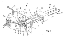
- Fig. 1 shows a double piston pump 1 in schematic view, which basic configuration is known in the art.
- Double piston pump 1 comprises conveying cylinders 3 and 4, in which conveying pistons 5 and 6, respectively, are movable.
- Double piston 1 comprises a feed hopper 7 comprising a housing 10, which on the rearward side is provided with a rearward plate 8. According to material feed arrow A 9 the material which is to be distributed by the double piston pump 1 is fed into feed hopper 7.
- Fig. 1 does not show material fed into feed hopper 7.
- transfer tube system (S-Weiche) 13 comprising transfer tube 14 to be alternately connected to opening 11 connected with conveying cylinder 3 and opening 12 connected to conveying cylinder 4.
- transfer tube 14 is swivelled between openings 11 and 12 via swivel lever 15 forming part of articulation means 17 fixed to rearward plate 8.
- articulation means 17 are not shown completely but are furthermore described with reference to Fig. 5 to 9 .
- FIG. 1 the material which is fed into feed hopper 7 according to arrow A is sucked into conveying cylinder 4 by retracting motion of conveying piston 6, which is schematically shown by arrow B.
- swivel lever 15 which comprises a tube portion 20 is in a position before opening 11 connecting transfer tube 14 with conveying cylinder 3.
- Conveying piston 5 moves in forward direction to rearward plate 8 leading to forwarding material which, according to arrow C is fed into a conveying pipe (not shown) to be distributed during operation.
- Conveying cylinders 3 and 4 are fixed to rearward plate 8 on one end and are housed in a housing 22 at their rearward end. As will be described below and not shown in Fig. 1 , conveying pistons 5 and 6 are driven by driving pistons 19 and 21, respectively (see Fig. 2 ) which are driven by hydraulic system 24 as shown in Fig. 2 .
- FIG. 2 showing the conveying piston drive mechanism 23 comprising a hydraulic drive system 24.
- drive piston 19 as well as drive piston 21 are configured conventionally. They both have the configuration of a double acting piston.
- Drive piston 19 comprises a piston head 25 housed in a cylinder housing 27. From piston head 25 a piston rod 29 is protruding and is connected for example to conveying piston 5.
- drive piston 21 comprises a piston head 31 housed in a cylinder housing 33. Piston head 31 is connected to a protruding piston rod 35 which is connected for example to conveying piston 6.
- pistons 25 and 31 together with piston rods 29 and 35 are moved in a corresponding direction leading to movement of conveying piston 5 and conveying piston 6 as shown in Fig. 1 in the corresponding direction.
- Line A is a line for feeding-in oil for conveying concrete or other materials and which is connected to the pump.
- Line B is the return run of oil into a (not shown) reservoir.
- Valve V3 is a direct acting four-way/three-position solenoid operated directional valve for piloting the four-way/three-position pilot-to-shift directional valve V5.
- Valve V4 is a check valve.
- Valve V5, which is the the main control valve, is hydraulically actuated by valve V3, and comprises a locking middle position. In this position lines A and B are short- circuited. Therefore, the maximum pump pressure delivered via line A is always present at valve V5.
- Valve V6 is a check valve and acts as back flow preventer during operation of high pressure pump for rock cleaning.
- Valve V7 is a volume control unit for rod-side feeding-in of oil and provides that return running cylinder being a little faster than forerunning cylinder as well as a compensation of oil conveying loss. Accordingly, the sucking in stroke of the corresponding conveying piston 5 or 6 is always ended a little time earlier than the pushing stroke of the respective other conveying cylinder 6 or 5. This shows that when switching of the transfer tube system is finished the corresponding conveying cylinder is fully prepared to start the pushing stroke.
- Valve V8 is a check valve and acts as a return run block of rod-side oil feeding-in.
- Valve V9 is a pressure relief valve of rod-side oil feeding-in and valve V16 is a shuffle valve for feeding-in rod-side of oil A.
- Main control valve V5 can be actuated very fast by solenoid valve V3, as only small pressure increase is required.
- Line T drains control hydraulic fluid from valve V3 to a reservoir (not shown)
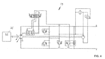
- Fig. 4 shows a block diagram of a conventional pump mechanism 39 which is marketed by the company Bosch Rexroth. As can be seen, the pump mechanism is driven by an electric motor 41. Electric motor 41 drives a pumping action of oil into line A. As this pump system is conventional and does not form part of the present invention, further description thereof is omitted.
- FIG. 3 showing a hydraulic system of the transfer tube system 13 (S-Weiche) of the present invention.
- Hydraulic system 43 is prepared to act on swivel or plunger cylinders 45 and 47. Those swivel or plunger cylinders 45, 47 are double acting as can be seen from Fig. 3 . However, the swivel or plunger cylinders 45 and 47 are shown only schematically and are described in more detail below with respect of Figures 6 to 9 .
- Valve V2 is a check valve provided as return run blocker, which blocks reservoir drain.
- Valve V3 is an orifice (Blende) for controlling drain of the reservoir when switching off valve V4.
- Valve V4 is a solenoid valve for draining to a reservoir (not shown).
- Valve V7 is a pressure reducing valve for reducing the operational pressure for acting the transfer tube system 13 as shown in Fig. 1 .
- Valve V9 is pressure control valve for limiting maximum pressure of the transfer tube system 13.
- Unit V10 is a flow control or volumetric control unit for adjusting the volume of oil for cleaning operation.
- Valve V12 is a solenoid valve for activating the transfer tube system 13.
- Valve V15 is also an orifice (Blende) for limiting volume to control valves V24 and V25, respectively.
- Valve V20 is an unlockable double check valve which is active during forerun of cylinder B and return run of cylinder A.
- Valve V21 is an unlockable double check valve, which is active during forerun of cylinder A and return run of cylinder B.
- Valve V22 is an unlockable double check valve, which is active during forerun of cylinder B and return run of cylinder A.
- Valve V23 is an unlockable double check valve, which is active during forerun of cylinder A and return run of cylinder B.
- Valve V24 is a solenoid valve for activating forerun of cylinder B whereas V25 is a solenoid valve for activating forerun of cylinder A.
- FIG. 5 is a view from behind of the feed hopper 7 showing the transfer tube system 13 in a middle position between openings 11 and 12.
- Tube portion 20 of swivel lever 15 is located between these openings 11 and 12 and swivel of plunger cylinders 45 and 47 are both also in a middle position. Swivel of plunger cylinders 45 and 47 will be described in more detail with reference to Figures 6 to 9 .
- the transfer tube system 13 comprises a plate 37 in which the openings 11 and 12 are located.
- the transfer tube system 13 comprises two arms 51 and 52.
- Arm 51 is provided with a bearing 54 to pivotable support swivel or plunger cylinder 45
- arm 52 is provided with a bearing 56 to for pivotable support swivel or plunger cylinder 47.
- Both swivel of plunger cylinders 45 and 47 are, at their other ends, pivotably connected to a control plate 53, which in turn is connected to swivel lever 15 in order to move swivel lever 15 from one opening 11, 12 to the other opening 12, 11.
- a control plate 53 which in turn is connected to swivel lever 15 in order to move swivel lever 15 from one opening 11, 12 to the other opening 12, 11.
- Swivel or plunger cylinder 47 comprises a cylinder body or housing 55 in which a hydraulic oil inlet/outlet 57 is provided at one end of the partly hollow housing 55 of swivel or plunger cylinder 47. Within the housing 55, there is provided a plunger 59 which is movable within housing 55.
- Plunger 59 is partly formed as a hollow body housing several specific elements inside. There is provided a spring package 61 for example in form of a laminated disc spring.
- a gas piston 63 which can be filled via a gas inlet/outlet 65, in which a check valve 66 is provided, wherein gas is guided to the gas piston 63 via internal line 67.
- a sealing kit 69 for sealing off the plunger 59 there is provided a sealing kit 69 and for sealing against escaping oil outside the housing 55.
- a feeding projection 60 is provided at the infeed end of plunger 59 comprising an inlet channel comprising a check valve 64.
- Check valve 64 is partly housed in a front plate 70 closing the the hollow plunger 59 at the hydraulic fluid or oil infeed end of plunger 59.
- an oil chamber 68 In the retracted position of Fig. 6 between gas piston 63 and front plate, there is provided an oil chamber 68 which is filled with oil in this position.
- Front plate 70 is provided with openings or nuts for example like a castellated nut. To fill in oil into chamber 68 oil is fed through channel 62 over check valve 64 which prevents oil from escaping chamber 68 back into channel 62.
- swivel or plunger cylinder 47 is shown in four different positions.
- Fig. 6 shows the complete retracted position before a stroke of plunger 59.
- Fig. 7 shows the cylinder extracted position where plunger 59 has reached its maximum extracted position.
- Fig. 8 shows a position during retracting movement of plunger 59 just before the start of the damping operation and
- Fig. 9 shows the position while damping of the plunger and loading gas accumulator for energy recuperation is carried out.
- plunger cylinder 47 is shown in its most extracted position. Oil is fed trough oil inlet 57 urging projection 60 to move away from its retracted position. Gas piston 63 urges oil out of chamber 68 to escape through openings (not shown) of front plate 70 into the hollow room left when plunger 59 moves away from its retracted position shown in Fig. 6 . Gas piston 63 urges oil to escape from chamber 68 until it abuts against front plate 70 as is shown in Fig. 7 .
- FIG. 8 there is shown plunger 47 during retracting movement in the position when damping of plunger 47 starts.
- Projection 70 reaches oil in inlet channel 58 and urges check valve 64 to open.
- oil in chamber 72 is urged to move through openings of front plate 70 to reinstall oil chamber 68, thereby moving gas piston 63 toward spring package 61. This increase the spring load of gas piston 63.
- Fig. 9 shows the position of plunger 47 shortly before reaching retracted end position of Fig. 6 .
- Oil chamber 68 is partly filled and oil chamber 72 is further reduced.
- plunger 47 With plunger 47 according to the present invention, there is provided a damping system which damps plunger when moving into its retracted position and an energy stored by gas piston 63 together with the spring package 21 is used during the next stroke of plunger 47 to accelerate its movement.
- a double piston pump with which an essentially constant conveying of fluid or semi-fluid materials, in particular concrete or cement is achieved overcoming the drawbacks of the prior art.
Landscapes
- Engineering & Computer Science (AREA)
- Mechanical Engineering (AREA)
- General Engineering & Computer Science (AREA)
- Reciprocating Pumps (AREA)
Abstract
- the hydraulic supply to the drive pistons (19, 21) is interrupted and said hydraulic circuit of the conveying pump is short-circuited by means of said main control valve (V5), and
- the delivery rate of the conveying pump is increased,
so that after the swivelling movement of the transfer tube (14) has been terminated and at the beginning of a next conveying cycle an increased supply output of the supplying conveying cylinder (5, 6) is carried out for a short term leading to a short-term increase of said supplied fluid or semi-fluid materials.
Description
- The present invention relates to a method for transmitting or conveying fluid or semi-fluid materials by means of a double piston pump. Furthermore, the present invention relates to a double piston pump for transmitting or conveying fluid or semi-fluid materials, in particular concrete or cement.
- Double piston pumps for the above-identified purposes are well known in the art. From
DE 42 15 403 C2 a double piston pump for transmitting or conveying fluid or semi-fluid materials, in particular concrete or cement is known comprising two conveying cylinders, each provided inside with a conveying piston, those conveying pistons being movable in an alternating push-pull manner. A feed hopper is provided for receiving material to be conveyed, which is fed by a material feed unit. A transfer tube system (S-Weiche) comprising a transfer tube which is connectable to a flow line or conveying pipes and is capable to connect said flow line or conveying pipes alternately with one of said conveying cylinders by means of articulation means, said articulation means comprising two swivel or plunger cylinders being hydraulically actuateable, the swivelling movement of said transfer tube being generated by said swivel or plunger cylinders. - A conveying piston drive mechanism comprising a drive piston for each conveying piston is provided in a hydraulic drive system, said drive pistons being connected to the dedicated conveying piston, wherein both drive pistons are supplied by a conveying pump, said supply being controllable by a valve. A main control valve is provided, with which alternating hydraulic supply to the corresponding drive piston is controlled. In principle, a double piston pump has the disadvantage, that during the switching movement of the transfer tube, there is a gap in transmitting or conveying the fluid or semi-fluid materials into the flow line leading to instable feeding, i. e. pulsations of the conveyed materials which is disadvantageous in many fields, in particular that of projecting concrete for covering tunnel walls.
- In order to compensate the gap in conveying the required materials, the double piston pump of
DE 42 15 403 C2 suggests a so called "push over"-system. This system shortly provides an additional amount of conveyed materials by increasing the speed of the acting conveying piston during the pushing cycle of the piston. - Although such a "push over"-system provides better performance of the double piston pump, some kind of pulsation still cannot be avoided. This results in particular from the fact that during switching of the transfer tube the materials are not conveyed.
- It is therefore an object of the present invention to provide a method for transmitting or conveying fluid or semi-fluid materials, in particular concrete or cement by means of a double piston pump, which provides a higher performance and, in particular, a reduced switching time of the transfer tube. It is also an object of the present invention to provide a double piston pump in particular to carry out the method.
- According to the present invention, during switching by swivelling movement of the transfer tube, the hydraulic supply to the drive pistons is interrupted and said hydraulic circuit of the conveying pump is short-circuited by means of said main control valve, and the delivery rate of the conveying pump is increased, so that after the swivelling movement of the transfer tube has been terminated and at the beginning of a next conveying cycle, an increased supply output of the supplying conveying cylinder is carried out for a short term leading to a short-term increase of said supplied fluid or semi-fluid materials.
- In other words, due to the short-circuiting of the conveying pump, the hydraulic cylinders of the drive pistons are no longer under pressure and the switching action of the transfer tube can be carried out at a maximum speed and a minimum time and due to the increase of the delivery rate of the conveying pump, there is provided an increased supply of oil to the respective hydraulic cylinder, leading to a short-term increase of said supplied fluid or semi-fluid materials, so that in operation a pulsation of the supplied materials is avoided or almost avoided.
- According to the present invention, after a short-time increase of the supply output of the conveying pump said supply output is reduced again to obtain a constant supply of fluid or semi-fluid materials.
- Furthermore, there is the advantage that by means of an auxiliary or pilot control valve said main control valve is controlled, wherein during moving of the transfer tube both said main control valve and said pilot control valve are brought into an inactive or neutral or middle position.
- A further advantage is that each swivel or plunger cylinder comprises a movable drive element or plunger, which, when reaching the final movement position, is damped.
- Action of the swivel or plunger cylinders is carried out with a minimum time and, therefore, with maximum speed of the drive elements or plungers. This results in the need of short braking the motion of said drive elements of plungers. Due to damping movement, the risk of damaging the swivel or plunger cylinders is drastically reduced.
- Furthermore, there is an advantage that when braking said movable drive element or plunger of said swivel or plunger cylinder said movable drive element or plunger is pre-stressed in the opposite direction, said pre-stress providing energy storing, in particular of kinetic energy.
- Furthermore, there is the advantage that during the next forward or pushing stroke of said movable drive element or plunger of said swivel or plunger cylinder said stored energy is regained such that said regained energy additionally accelerates said movable driver element or plunger. Therefore, the time for switching the transfer tube can be further reduced leading to a drastic reduction of negative pulsation of the system.
- The present invention is also directed to a double piston pump transmitting or conveying fluid or semi-fluid materials, in particular concrete or cement. According to the invention, a double piston pump is characterised in that during swivelling movement of the transfer tube the hydraulic supply to the drive pistons is interrupted and said hydraulic circuit of the conveying pump is short-circuited by means of said main control valve, and the conveying pump increases its delivery rate, so that after the swivelling movement of the transfer tube has been terminated and at the beginning the next conveying cycle, an increased supply output of the supplying conveying cylinder is carried out for a short term leading to a short-time increase of said supplied fluid or semi-fluid materials.
- Again, with this short-term increase of said supplied materials, the gap of conveying during the swivelling movement of the transfer tube can be filled shortly afterwards leading to a rather constant conveying of materials without pulsations.
- There is the advantage that each swivel or plunger cylinder comprises a movable drive element, in particular a plunger, being movable in a forward or extracting and a backward or retracting stroke, wherein said movable drive element or plunger is damped at least when reaching its end-position of the retracting stroke.
- Furthermore, each swivel or plunger cylinder comprises a piston filled with gaseous material and a spring package acting against said piston, resulting in a braking of the movable drive element or plunger, so that the movement of said drive element or plunger can be damped avoiding harm of the transfer tube system.
- Furthermore, there is the advantage, that during braking of the movable drive element or plunger of said swivel or plunger cylinder, said movable drive element or plunger provides a pretension or pre-stress of said spring package and/or of the piston, wherein an energy store is carried out, in particular of kinetic energy.
- This, advantageously, leads to the result that during the next forward stroke of the movable drive element or plunger of the swivel or plunger cylinder the stored energy is regained, such that said stored energy additionally accelerates said movable drive element or plunger.
- Further details, features and advantages will become evident from the following specification or preferred embodiments of the present invention with reference to the enclosed drawings. In these drawings:
- Fig. 1
- shows a perspective view of one embodiment of the double piston pump according to the present invention;
- Fig. 2
- shows a block diagram of the hydraulic block conveying;
- Fig. 3
- shows a block diagram of the hydraulic block of the transfer tube system (S-Weiche);
- Fig. 4
- shows a block diagram of a conventional conveying pump system for example produced by Bosch Rexroth;
- Fig. 5
- shows a back side view of the transfer tube system with two swivel or plunger cylinders, said transfer tube system being seated in a middle position during swivelling from one conveying cylinder to the other;
- Fig.6
- shows a section view of the left-hand swivel or plunger cylinder of
Fig. 5 at the beginning of the extension movement, i.e. the retracted position; - Fig. 7
- shows the section view of the left-hand swivel or plunger cylinder according to
Fig. 6 in its most extended position; - Fig. 8
- shows the section view of the left-hand swivel or plunger cylinder according to
Fig. 6 during its retracting movement just before damping; and - Fig. 9
- shows the section view of the left-hand swivel or plunger cylinder according to
Fig. 6 during damping operation while retracting. - In the drawings the same elements are referenced with the same reference signs. The drawings show a preferred embodiment of the present invention. However, the present invention is not limited to this embodiment and alternative embodiments are also covered by the subject matter as described in the claims.
-
Fig. 1 shows a double piston pump 1 in schematic view, which basic configuration is known in the art. Double piston pump 1 comprises conveyingcylinders 3 and 4, in which conveyingpistons 5 and 6, respectively, are movable. Double piston 1 comprises afeed hopper 7 comprising ahousing 10, which on the rearward side is provided with a rearward plate 8. According to material feed arrow A 9 the material which is to be distributed by the double piston pump 1 is fed intofeed hopper 7.Fig. 1 does not show material fed intofeed hopper 7. - Onto rearward plate 8 is fixed a transfer tube system (S-Weiche) 13 comprising
transfer tube 14 to be alternately connected to opening 11 connected with conveyingcylinder 3 and opening 12 connected to conveying cylinder 4. According todouble arrow 16transfer tube 14 is swivelled betweenopenings 11 and 12 viaswivel lever 15 forming part of articulation means 17 fixed to rearward plate 8. InFig. 1 the articulation means 17 are not shown completely but are furthermore described with reference toFig. 5 to 9 . - As can be seen from
Fig. 1 the material which is fed intofeed hopper 7 according to arrow A is sucked into conveying cylinder 4 by retracting motion of conveying piston 6, which is schematically shown by arrow B. - At the same
time swivel lever 15, which comprises atube portion 20 is in a position before opening 11 connectingtransfer tube 14 with conveyingcylinder 3. Conveyingpiston 5 moves in forward direction to rearward plate 8 leading to forwarding material which, according to arrow C is fed into a conveying pipe (not shown) to be distributed during operation. - Conveying
cylinders 3 and 4 are fixed to rearward plate 8 on one end and are housed in ahousing 22 at their rearward end. As will be described below and not shown inFig. 1 , conveyingpistons 5 and 6 are driven by drivingpistons Fig. 2 ) which are driven byhydraulic system 24 as shown inFig. 2 . - The operation mould of double piston pump 1 according to
Fig. 1 , can be described as follows. Conveyingpiston 5 as shown inFig. 1 is in its pumping or conveying stroke in forward direction to rearward plate 8 urging material, which has been sucked in into conveyingcylinder 3 from the feed hopper during opening 11, intotransfer tube 14 according to arrow C. In order to provide a connection betweentransfer tube 14 and conveyingcylinder 3 articulation means 17 swivelledswivel lever 15 and inparticular tube portion 20 before opening 11 to provide connection between conveyingcylinder 3 and transfertube 14. - When conveying
piston 5 has reached its most forward position, i. e. all material or essentially all material provided by conveyingcylinder 3 has been distributed intotransfer tube 14, articulation means 17 are activated to swivelswivel lever 15 according todouble arrow 16 into a position to coveropening 12 connected to conveying cylinder 4, which had been filled with material according to arrow B by suction stroke of conveying piston 6 during pumping stroke of conveyingpiston 5. - During swivel movement of
swivel lever 15 conveyingpiston drive mechanism 23, which will be described in more detail with reference toFig. 2 below, changes from suction stroke of conveying piston 6 into pushing stroke and at the same time from pushing stroke of conveyingpiston 5 into suction stroke of conveyingpiston 5. After conveyingpiston 5 has reached the end of the suction stroke and conveying piston 6 has reached the end of the pushing stroke, the articulation means 17 again move saidswivel lever 15 from opening 12 to opening 11, in order to connect conveyingcylinder 3 to transfertube 14. - Reference is now made to
Fig. 2 showing the conveyingpiston drive mechanism 23 comprising ahydraulic drive system 24. - As can be seen from
Fig. 2 drive piston 19 as well asdrive piston 21 are configured conventionally. They both have the configuration of a double acting piston. Drivepiston 19 comprises apiston head 25 housed in acylinder housing 27. From piston head 25 apiston rod 29 is protruding and is connected for example to conveyingpiston 5. Similarly,drive piston 21 comprises apiston head 31 housed in acylinder housing 33.Piston head 31 is connected to a protrudingpiston rod 35 which is connected for example to conveying piston 6. When thehydraulic drive system 24 is actuatedpistons piston rods piston 5 and conveying piston 6 as shown inFig. 1 in the corresponding direction. - With reference to
Fig. 2 thehydraulic drive system 24 of the present invention will be described in more detail. Line A is a line for feeding-in oil for conveying concrete or other materials and which is connected to the pump. Line B is the return run of oil into a (not shown) reservoir. Valve V3 is a direct acting four-way/three-position solenoid operated directional valve for piloting the four-way/three-position pilot-to-shift directional valve V5. Valve V4 is a check valve. Valve V5, which is the the main control valve, is hydraulically actuated by valve V3, and comprises a locking middle position. In this position lines A and B are short- circuited. Therefore, the maximum pump pressure delivered via line A is always present at valve V5. - Valve V6 is a check valve and acts as back flow preventer during operation of high pressure pump for rock cleaning. Valve V7 is a volume control unit for rod-side feeding-in of oil and provides that return running cylinder being a little faster than forerunning cylinder as well as a compensation of oil conveying loss. Accordingly, the sucking in stroke of the corresponding conveying
piston 5 or 6 is always ended a little time earlier than the pushing stroke of the respective other conveyingcylinder 6 or 5. This shows that when switching of the transfer tube system is finished the corresponding conveying cylinder is fully prepared to start the pushing stroke. - Valve V8 is a check valve and acts as a return run block of rod-side oil feeding-in. Valve V9 is a pressure relief valve of rod-side oil feeding-in and valve V16 is a shuffle valve for feeding-in rod-side of oil A.
- Main control valve V5 can be actuated very fast by solenoid valve V3, as only small pressure increase is required. Line T drains control hydraulic fluid from valve V3 to a reservoir (not shown)
- When main control pilot operated valve V5 is moved to the right, then drive
piston 21 is activated aspiston 31 is pushed leading to a pushing stroke of the corresponding conveying piston 6. When the pushing stroke ofdrive piston 21 is finished, main control valve V5 is moved into the middle position thereby short-circuiting feed-in line A with line B leading to the big advantage, that full pressure in line A is available when moving main control valve V5 to the left so that oil is now fed to drivingcylinder 19, immediately starting movement of drivingcylinder 19. During the middle position of valve V5 hydraulic pump is switched to increased pumping power. When valve V5 is switched to the next operating position increased hydraulic pressure is delivered to the respective forerun cylinder leading in an increased driving speed of the piston. This leads to an increased feeding of material intotransfer tube 14. -
Fig. 4 shows a block diagram of aconventional pump mechanism 39 which is marketed by the company Bosch Rexroth. As can be seen, the pump mechanism is driven by anelectric motor 41.Electric motor 41 drives a pumping action of oil into line A. As this pump system is conventional and does not form part of the present invention, further description thereof is omitted. - Reference is now made to
Fig. 3 showing a hydraulic system of the transfer tube system 13 (S-Weiche) of the present invention. -
Hydraulic system 43 is prepared to act on swivel orplunger cylinders plunger cylinders Fig. 3 . However, the swivel orplunger cylinders Figures 6 to 9 . - The components of the
hydraulic system 43 are as follows. Valve V2 is a check valve provided as return run blocker, which blocks reservoir drain. Valve V3 is an orifice (Blende) for controlling drain of the reservoir when switching off valve V4. Valve V4 is a solenoid valve for draining to a reservoir (not shown). - Valve V7 is a pressure reducing valve for reducing the operational pressure for acting the
transfer tube system 13 as shown inFig. 1 . Valve V9 is pressure control valve for limiting maximum pressure of thetransfer tube system 13. Unit V10 is a flow control or volumetric control unit for adjusting the volume of oil for cleaning operation. - Valve V12 is a solenoid valve for activating the
transfer tube system 13. Valve V15 is also an orifice (Blende) for limiting volume to control valves V24 and V25, respectively. Valve V20 is an unlockable double check valve which is active during forerun of cylinder B and return run of cylinder A. Valve V21 is an unlockable double check valve, which is active during forerun of cylinder A and return run of cylinder B. Valve V22 is an unlockable double check valve, which is active during forerun of cylinder B and return run of cylinder A. Valve V23 is an unlockable double check valve, which is active during forerun of cylinder A and return run of cylinder B. Valve V24 is a solenoid valve for activating forerun of cylinder B whereas V25 is a solenoid valve for activating forerun of cylinder A. - Furthermore, there is provided a
hydraulic accumulator 49 to supply a sufficient amount of instant hydraulic power when switching. - This specific configuration of all valves can be derived from the specific symbols of the systems shown in
Figures 2 to 4 but are not limited thereto. Different embodiments leading to same or essentially same effects still fall under the scope of the present invention. FromFig. 2 to 4 the connecting lines between the components can clearly be derived and are not explained in more detail. - With reference to
Fig. 5 , thetransfer tube system 13 is described in more detail.Fig. 5 is a view from behind of thefeed hopper 7 showing thetransfer tube system 13 in a middle position betweenopenings 11 and 12.Tube portion 20 ofswivel lever 15 is located between theseopenings 11 and 12 and swivel ofplunger cylinders plunger cylinders Figures 6 to 9 . - As can be seen from
Fig. 5 in this embodiment, thetransfer tube system 13 comprises aplate 37 in which theopenings 11 and 12 are located. Thetransfer tube system 13 comprises twoarms Arm 51 is provided with abearing 54 to pivotable support swivel orplunger cylinder 45, whereasarm 52 is provided with abearing 56 to for pivotable support swivel orplunger cylinder 47. Both swivel ofplunger cylinders control plate 53, which in turn is connected to swivellever 15 in order to moveswivel lever 15 from oneopening 11, 12 to theother opening 12, 11. InFig. 5 the connections of swivel orplunger cylinders hydraulic system 43 driving both swivel orplunger cylinders Fig. 1 is not shown inFig. 5 - Reference is now made to
Figures 6 to 9 in which swivel ofplunger cylinder 47 is shown in partly cut off sectional view in different positions during movement in order to provide required movement of theswivel lever 15 to alternately connecttransfer tube 14 withopenings 11 and 12, respectively. Swivel orplunger cylinder 45 is configured accordingly. - Swivel or
plunger cylinder 47 comprises a cylinder body orhousing 55 in which a hydraulic oil inlet/outlet 57 is provided at one end of the partlyhollow housing 55 of swivel orplunger cylinder 47. Within thehousing 55, there is provided aplunger 59 which is movable withinhousing 55. -
Plunger 59 is partly formed as a hollow body housing several specific elements inside. There is provided aspring package 61 for example in form of a laminated disc spring. One aim which is realised by the present invention is to provide a swivel movement of the transfer tube system within a minimum of time which is able to last for a long time performing very high number of strokes. Withinplunger 59 there is provided agas piston 63 which can be filled via a gas inlet/outlet 65, in which acheck valve 66 is provided, wherein gas is guided to thegas piston 63 viainternal line 67. For sealing off theplunger 59 there is provided asealing kit 69 and for sealing against escaping oil outside thehousing 55. - Via opening 71
housing 55 of swivel orplunger cylinder 47 is able to be connected to arm 52 (seeFig. 5 ), whereas via opening 73plunger 59 is able to be connected tocentral plate 53. - A feeding
projection 60 is provided at the infeed end ofplunger 59 comprising an inlet channel comprising acheck valve 64. Checkvalve 64 is partly housed in afront plate 70 closing the thehollow plunger 59 at the hydraulic fluid or oil infeed end ofplunger 59. In the retracted position ofFig. 6 betweengas piston 63 and front plate, there is provided anoil chamber 68 which is filled with oil in this position.Front plate 70 is provided with openings or nuts for example like a castellated nut. To fill in oil intochamber 68 oil is fed throughchannel 62 overcheck valve 64 which prevents oil from escapingchamber 68 back intochannel 62. - The swivel or
plunger cylinder 47 is shown in four different positions.Fig. 6 shows the complete retracted position before a stroke ofplunger 59.Fig. 7 shows the cylinder extracted position whereplunger 59 has reached its maximum extracted position.Fig. 8 shows a position during retracting movement ofplunger 59 just before the start of the damping operation andFig. 9 shows the position while damping of the plunger and loading gas accumulator for energy recuperation is carried out. - In
Fig. 7 plunger cylinder 47 is shown in its most extracted position. Oil is fedtrough oil inlet 57 urgingprojection 60 to move away from its retracted position.Gas piston 63 urges oil out ofchamber 68 to escape through openings (not shown) offront plate 70 into the hollow room left whenplunger 59 moves away from its retracted position shown inFig. 6 .Gas piston 63 urges oil to escape fromchamber 68 until it abuts againstfront plate 70 as is shown inFig. 7 . - From
Fig. 8 there is shownplunger 47 during retracting movement in the position when damping ofplunger 47 starts.Projection 70 reaches oil ininlet channel 58 and urges checkvalve 64 to open. Simultaneously oil inchamber 72 is urged to move through openings offront plate 70 to reinstalloil chamber 68, thereby movinggas piston 63 towardspring package 61. This increase the spring load ofgas piston 63. -
Fig. 9 shows the position ofplunger 47 shortly before reaching retracted end position ofFig. 6 .Oil chamber 68 is partly filled andoil chamber 72 is further reduced. - With
plunger 47 according to the present invention, there is provided a damping system which damps plunger when moving into its retracted position and an energy stored bygas piston 63 together with thespring package 21 is used during the next stroke ofplunger 47 to accelerate its movement. - With the present invention there is provided a double piston pump with which an essentially constant conveying of fluid or semi-fluid materials, in particular concrete or cement is achieved overcoming the drawbacks of the prior art. In particular, a very short movement of the swivel or
plunger cylinders plunger 59 againsthousing 55. -
- 1 - double piston pump
- 3 - conveying cylinder
- 4 - conveying cylinder
- 5 - conveying piston
- 6 - conveying piston
- 7 - feed hopper
- 8 - rearward plate
- 9 - material feed arrow A
- 10 - housing
- 11 - opening
- 12 - opening
- 13 - transfer tube system (S-Weiche)
- 14 - transfer tube
- 15 - swivel lever
- 16 - double arrow
- 17 - articulation means
- 19 - drive piston
- 20 - tube portion
- 21 - drive piston
- 22 - housing
- 23 - conveying piston drive mechanism
- 24 - hydraulic drive system
- 25 - piston head
- 27 - cylinder housing
- 29 - piston rod
- 31 - piston head
- 33 - cylinder housing
- 35 - piston rod
- 37 - plate
- 39 - pump mechanism
- 41 - electric motor
- 43 - hydraulic system
- 45 - swivel or plunger cylinder
- 47 - swivel or plunger cylinder
- 49 - hydraulic accumulator to supply a sufficient amount of instant hydraulic power when switching
- 51 - arm
- 52 - arm
- 53 - central plate
- 54 - bearing
- 55 - cylinder body
- 56 - bearing
- 57 - hydraulic oil inlet/outlet
- 59 - plunger
- 60 - feeding and draining projection
- 61 - spring package
- 62 - inlet channel
- 63 - gas piston
- 64 - check valve
- 65 - gas inlet/outlet
- 66 - check valve
- 67 - internal gas line
- 68 - oil chamber
- 69 - sealing kit
- 70 - front plate
- 71 - opening
- 72 - oil chamber
- 73 - opening
- List of components in hydraulic circuits:
- 1. Hydraulic drive mechanism (
Fig. 2 ):- A:
- feeding-in oil for conveying concrete,
- B:
- return run of oil from conveying concrete
- V3:
- direct acting four-way/three-position solenoid operated directional pilot valve for piloting V5
- V4:
- check valve
- V5:
- hydraulically activated main control four-way/three-position pilot-to-shift directional valve for conveying forerun A
- V6:
- backflow preventer active during operation of high pressure pump for rock cleaning
- V7
- volume control unit for rod side feeding-in of oil (return running cylinder being little faster than forerunning cylinder as well as compensation of oil conveying loss)
- V8:
- check valve and return run blocker of rod side oil feeding-in
- V9:
- pressure relief of rod side oil feeding-in
- V16:
- shuffle valve for feeding-in rod side oil of A as well as of B
- 2. Hydraulic drive mechanism of transfer tube system (
Fig. 3 ):- P:
- pump line and connection to fluid pump(not used in this system)
- T:
- reservoir return connection
- V2:
- check valve (return run blocker) blocks reservoir drain
- V3:
- orifice (Blende) for controlled drain of reservoir when switching off valve V4
- V4:
- solenoid valve for draining reservoir
- V7:
- pressure reducing valve for reducing the operational pressure for acting the transfer tube system
- V9:
- pressure control valve for limiting maximum pressure of the transfer tube system
- V10:
- flow control or volumetric control unit for adjusting the volume of oil for cleaning operation
- V12:
- solenoid valve for activating the transfer tube system
- V15:
- orifice (Blende) for limiting volume to control valves V24 and V25, respectively
- V20:
- unlockable double check valve active during forerun of cylinder B and return run of cylinder A
- V21:
- unlockable double check valve active during forerun of cylinder A and return run of cylinder B
- V22:
- unlockable double check valve active during forerun of cylinder B and return run of cylinder A
- V23:
- unlockable double check valve active during forerun of cylinder A and return run of cylinder B
- V24:
- solenoid valve for activating forerun of cylinder B
- V25:
- solenoid valve for activating forerun of cylinder A
Claims (12)
- A method for transmitting or conveying fluid or semi-fluid materials, in particular concrete or cement, by means of a double piston pump (1), which comprises
two conveying cylinders (3, 4), each provided inside with a conveying piston (5, 6), said conveying pistons (5, 6) being movable in an alternating push-pull manner,
a feed hopper (7) for receiving material to be conveyed, which is fed by a material feed unit,
a transfer tube system (13) comprising a transfer tube (14), which is connectable to a flow line or conveying pipes and is capable to connect said flow line or conveying pipes alternately with one of said conveying cylinders (3, 4) by means of articulation means (17), said articulation means (17) comprising two swivel or plunger cylinders (45, 47) being hydraulically actuateable, the swivelling movement of said transfer tube (14) being generated by said swivel or plunger cylinders (45, 47),
a conveying piston drive mechanism (23) comprising a drive piston (19, 21) for each conveying piston (5, 6) provided in a hydraulic drive system (24), said drive pistons (19, 21) being connected to the dedicated conveying piston (5, 6), wherein both drive pistons (19, 21) are supplied by a conveying pump (39) being provided in a hydraulic circuit, said supply being controllable by a valve, and
a main control valve (V5) with which the alternating hydraulic supply to the corresponding drive piston (19, 21) is controlled,
characterised in that
during swivelling movement of the transfer tube (14):- the hydraulic supply to the drive pistons (19, 21) is interrupted and said hydraulic circuit of the conveying pump is short-circuited by means of said main control valve (V5), and- the delivery rate of the conveying pump is increased,so that after the swivelling movement of the transfer tube (14) has been terminated and at the beginning of a next conveying cycle an increased supply output of the supplying conveying cylinder (5, 6) is carried out for a short term leading to a short-term increase of said supplied fluid or semi-fluid materials. - The method according to claim 1, characterised in that after short-time increase of the supply output of the conveying pump said supply output is reduced again.
- The method according to claim 1 or 2, characterised in that by means of an pilot control valve (V3) said main control valve (V5) is controlled, wherein during movement of the transfer tube (14) both said main control valve (V5) and said pilot control valve (V3) are brought into an inactive or neutral or middle position.
- The method according to one of the claims 1 to 3, characterised in that each swivel or plunger cylinder (45, 47) comprises a movable drive element or plunger (59), which, when reaching the final movement position, is damped.
- The method according to claim 4, characterised in that when braking said movable drive element or plunger (59) of said swivel or plunger cylinder (45, 47) said movable drive element or plunger (59) is pre-stressed in the opposite direction, said pre-stress providing energy storing, in particular of kinetic energy.
- The method according to claim 5, characterised in that during the next forward stroke of said movable drive element or plunger (59) of said swivel or plunger cylinder (45, 47) said stored energy is regained such that said regained energy additionally accelerates said movable drive element or plunger (59).
- A double piston pump (1) for transmitting or conveying fluid or semi-fluid materials, in particular concrete or cement, comprising
two conveying cylinders (3, 4), each provided inside with a conveying piston (5, 6), said conveying pistons (5, 6) being movable in an alternating push-pull manner,
a feed hopper (7) for receiving material to be conveyed, which is fed by a material feed unit,
a transfer tube system (13) comprising a transfer tube (14), which is connectable to a flow line or conveying pipes and is capable to connect said flow line or conveying pipes alternately with one of said conveying cylinders (3, 4) by means of articulation means (17), said articulation means (17) comprising two swivel or plunger cylinders (45, 47) being hydraulically actuateable, the swivelling movement of said transfer tube (14) being generated by said swivel or plunger cylinders (45, 47),
a conveying piston drive mechanism (23) comprising a drive piston (19, 21) for each conveying piston (5, 6) provided in a hydraulic drive system (24), said drive pistons (19, 21) being connected to the dedicated conveying piston (5, 6), wherein both drive pistons (19, 21) are supplied by a conveying pump (39) being provided in a hydraulic circuit, said supply being controllable by a valve, and
a main control valve (V5) with which the alternating hydraulic supply to the corresponding drive piston (19, 21) is controlled,
characterised in that
during swivelling movement of the transfer tube (14):- the hydraulic supply to the drive pistons (19, 21) is interrupted and said hydraulic circuit of the conveying pump is short-circuited by means of said main control valve (V5), and- the conveying pump increases the delivery rate,so that after the swivelling movement of the transfer tube (14) has been terminated and at the beginning of a next conveying cycle an increased supply output of the supplying conveying cylinder (5, 6) is carried out for a short term leading to a short-term increase of said supplied fluid or semi-fluid materials. - The double piston pump according to claim 7, characterised in that said main control valve (V5) is hydraulically activateable by means of an pilot control valve (V3).
- The double piston pump (1) according to claim 7 or 8, characterised in that each swivel or plunger cylinder (45, 47) comprises a movable drive element, in particular a plunger (59), being movable in a forward or extracting and a backward or retracting stroke, wherein said movable drive element or plunger (59) is damped at least when reaching its end-position of the retracting stroke.
- The double piston pump (1) according to claim 9, characterised in that each swivel or plunger cylinder (45, 47) comprises a piston (63) filled with gaseous material and a spring package (61) acting against said piston (63), resulting in a braking of the movable drive element or plunger (59).
- The double piston pump (1) according to claim 10, characterised in that during braking of the movable drive element or plunger (59) of said swivel or plunger cylinder (45, 47) said movable drive element or plunger (59) provides a pretension or pre-stress of said spring package (61) and/or of said piston (63), wherein an energy store is carried out, in particular of kinetic energy.
- The double piston pump (1) according to claim 11, characterised in that during the next forward stroke of the movable drive element or plunger (59) of the swivel or plunger cylinder (45, 47) the stored energy is regained, such that said stored energy additionally accelerates said movable drive element or plunger (59).
Priority Applications (5)
| Application Number | Priority Date | Filing Date | Title |
|---|---|---|---|
| ES16164647.6T ES2687175T3 (en) | 2016-04-11 | 2016-04-11 | Method for transmitting or transporting fluid or semi-fluid materials by means of a double piston pump and double piston pump for it |
| EP16164647.6A EP3232057B1 (en) | 2016-04-11 | 2016-04-11 | Method for transmitting or conveying fluid or semi-fluid materials by means of a double piston pump and double piston pump therefor |
| CA3012564A CA3012564A1 (en) | 2016-04-11 | 2017-04-03 | Method for transmitting or conveying fluid or semi-fluid materials by means of a double piston pump and double piston pump therefor |
| CN201780018269.4A CN108779767B (en) | 2016-04-11 | 2017-04-03 | Method for conveying or transporting fluid or semi-fluid material by means of double-piston pump and double-piston pump thereof |
| PCT/EP2017/057818 WO2017178261A1 (en) | 2016-04-11 | 2017-04-03 | Method for transmitting or conveying fluid or semi-fluid materials by means of a double piston pump and double piston pump therefor |
Applications Claiming Priority (1)
| Application Number | Priority Date | Filing Date | Title |
|---|---|---|---|
| EP16164647.6A EP3232057B1 (en) | 2016-04-11 | 2016-04-11 | Method for transmitting or conveying fluid or semi-fluid materials by means of a double piston pump and double piston pump therefor |
Publications (2)
| Publication Number | Publication Date |
|---|---|
| EP3232057A1 true EP3232057A1 (en) | 2017-10-18 |
| EP3232057B1 EP3232057B1 (en) | 2018-06-13 |
Family
ID=55808364
Family Applications (1)
| Application Number | Title | Priority Date | Filing Date |
|---|---|---|---|
| EP16164647.6A Active EP3232057B1 (en) | 2016-04-11 | 2016-04-11 | Method for transmitting or conveying fluid or semi-fluid materials by means of a double piston pump and double piston pump therefor |
Country Status (5)
| Country | Link |
|---|---|
| EP (1) | EP3232057B1 (en) |
| CN (1) | CN108779767B (en) |
| CA (1) | CA3012564A1 (en) |
| ES (1) | ES2687175T3 (en) |
| WO (1) | WO2017178261A1 (en) |
Cited By (2)
| Publication number | Priority date | Publication date | Assignee | Title |
|---|---|---|---|---|
| CN113700626A (en) * | 2021-09-07 | 2021-11-26 | 湖南嘉顺华新材料有限公司 | Stable and reliable slurry plunger pump with automatic pressure control function |
| CN114956289A (en) * | 2022-06-29 | 2022-08-30 | 长春电子科技学院 | Automatic pesticide spraying mechanical system for sewage environment-friendly purification treatment |
Families Citing this family (9)
| Publication number | Priority date | Publication date | Assignee | Title |
|---|---|---|---|---|
| CN111792382B (en) * | 2019-04-09 | 2024-05-28 | 航天长征化学工程股份有限公司 | Multi-piece plunger type powder pressurized conveying device |
| CN110043438A (en) * | 2019-05-24 | 2019-07-23 | 徐州徐工施维英机械有限公司 | Pasty material conveying device and engineering truck |
| CN110547063B (en) * | 2019-09-04 | 2022-01-11 | 山东弘宇农机股份有限公司 | Multifunctional hydraulic lifter assembly |
| EP4219942B1 (en) * | 2020-04-30 | 2024-11-27 | Robatech AG | Double-acting piston pump, and application system for applying a flowable medium to a substrate |
| CN115370964B (en) * | 2022-08-01 | 2024-08-27 | 中国煤炭地质总局勘查研究总院 | A flow-aiding device for conveying grouting material in pipeline |
| CN116136207B (en) * | 2023-03-29 | 2024-12-10 | 湖南鹏翔星通汽车有限公司 | A double suction device for a pumping system |
| CN117306869B (en) * | 2023-11-23 | 2025-11-25 | 山东耀华特耐科技有限公司 | Refractory material pumping and lifting equipment |
| CN119825426B (en) * | 2025-03-20 | 2025-06-24 | 山西辰润交通科技有限公司 | Concrete injection apparatus for tunnel construction |
| CN121184332B (en) * | 2025-11-24 | 2026-02-27 | 四川轻化工大学 | A feed pump for a dry anaerobic fermentation tank that is not prone to clogging |
Citations (5)
| Publication number | Priority date | Publication date | Assignee | Title |
|---|---|---|---|---|
| DE9217574U1 (en) * | 1992-12-23 | 1993-05-27 | Langerbein-Scharf GmbH & Co. KG, 4700 Hamm | Control arrangement for a multi-cylinder slurry pump |
| DE4318267A1 (en) * | 1993-06-02 | 1994-12-08 | Lsb Langerbein Scharf Gmbh & C | Multi-cylinder feed pump for thick matter or the like |
| JPH08338407A (en) * | 1995-06-14 | 1996-12-24 | Tadano Ltd | Force feed device for fluid |
| DE4215403C2 (en) | 1991-05-16 | 2000-10-19 | Mbt Holding Ag Zuerich | Double piston pump for pumping liquid materials, especially concrete or mortar |
| WO2014044000A1 (en) * | 2012-09-19 | 2014-03-27 | 中联重科股份有限公司 | Jumping-proof stopping method of dual-cylinder pumping system, dual-cylinder pumping system, and pumping equipment |
Family Cites Families (4)
| Publication number | Priority date | Publication date | Assignee | Title |
|---|---|---|---|---|
| DE102004015416A1 (en) * | 2004-03-26 | 2005-10-13 | Putzmeister Ag | Apparatus and method for controlling a slurry pump |
| DE102004025910B4 (en) * | 2004-05-27 | 2009-05-20 | Schwing Gmbh | Drive device for a two-cylinder high-pressure pump and method for operating the same |
| DE102012216242A1 (en) * | 2012-09-13 | 2014-03-13 | Putzmeister Engineering Gmbh | Device for drive control of a two-cylinder slurry pump |
| CN102979693B (en) * | 2012-11-27 | 2015-08-19 | 长安大学 | A kind of device and controlling method thereof realizing the pumping of concrete continuous constant flow |
-
2016
- 2016-04-11 ES ES16164647.6T patent/ES2687175T3/en active Active
- 2016-04-11 EP EP16164647.6A patent/EP3232057B1/en active Active
-
2017
- 2017-04-03 CA CA3012564A patent/CA3012564A1/en active Pending
- 2017-04-03 CN CN201780018269.4A patent/CN108779767B/en active Active
- 2017-04-03 WO PCT/EP2017/057818 patent/WO2017178261A1/en not_active Ceased
Patent Citations (5)
| Publication number | Priority date | Publication date | Assignee | Title |
|---|---|---|---|---|
| DE4215403C2 (en) | 1991-05-16 | 2000-10-19 | Mbt Holding Ag Zuerich | Double piston pump for pumping liquid materials, especially concrete or mortar |
| DE9217574U1 (en) * | 1992-12-23 | 1993-05-27 | Langerbein-Scharf GmbH & Co. KG, 4700 Hamm | Control arrangement for a multi-cylinder slurry pump |
| DE4318267A1 (en) * | 1993-06-02 | 1994-12-08 | Lsb Langerbein Scharf Gmbh & C | Multi-cylinder feed pump for thick matter or the like |
| JPH08338407A (en) * | 1995-06-14 | 1996-12-24 | Tadano Ltd | Force feed device for fluid |
| WO2014044000A1 (en) * | 2012-09-19 | 2014-03-27 | 中联重科股份有限公司 | Jumping-proof stopping method of dual-cylinder pumping system, dual-cylinder pumping system, and pumping equipment |
Cited By (3)
| Publication number | Priority date | Publication date | Assignee | Title |
|---|---|---|---|---|
| CN113700626A (en) * | 2021-09-07 | 2021-11-26 | 湖南嘉顺华新材料有限公司 | Stable and reliable slurry plunger pump with automatic pressure control function |
| CN114956289A (en) * | 2022-06-29 | 2022-08-30 | 长春电子科技学院 | Automatic pesticide spraying mechanical system for sewage environment-friendly purification treatment |
| CN114956289B (en) * | 2022-06-29 | 2023-07-25 | 长春电子科技学院 | Automatic medicine mechanical system that spills that sewage environmental protection purification treatment used |
Also Published As
| Publication number | Publication date |
|---|---|
| CN108779767A (en) | 2018-11-09 |
| WO2017178261A1 (en) | 2017-10-19 |
| EP3232057B1 (en) | 2018-06-13 |
| ES2687175T3 (en) | 2018-10-24 |
| CN108779767B (en) | 2020-01-21 |
| CA3012564A1 (en) | 2017-10-19 |
Similar Documents
| Publication | Publication Date | Title |
|---|---|---|
| EP3232057B1 (en) | Method for transmitting or conveying fluid or semi-fluid materials by means of a double piston pump and double piston pump therefor | |
| US6641371B2 (en) | Device for continuous regulation of the gas flow rate processed by a reciprocating compressor | |
| US20030167936A1 (en) | Controller for a hydraulic press and method for the operation thereof | |
| GB1068863A (en) | Improvements in or relating to reciprocating pumps | |
| EP0197632B1 (en) | Actuator for a reciprocating slurry pump | |
| US4462763A (en) | Hydraulic pump jack | |
| CN104329306B (en) | A kind of hydraulic control system, method and pump | |
| EP0118497B1 (en) | Hydraulically actuated bore and well pump | |
| CN110118169A (en) | A kind of hydraulic concrete double-piston pump commutation current stabilization control system | |
| US12618423B2 (en) | Oil drain valve, energy accumulation device, hydraulic system and working machine | |
| US3494290A (en) | Control system for concrete pump | |
| WO2024061722A1 (en) | Mechanically decoupled double rod linear actuator | |
| GB2175352A (en) | Hydraulic pulseless supply means | |
| GB1291331A (en) | Concrete pump assemblies | |
| DE3479911D1 (en) | Hydraulic circuit for the control of reciprocating pistons pump | |
| JP5985555B2 (en) | Pump | |
| US4456438A (en) | Extrusion device for impregnating a rock formation, preferably for bonding with a liquid synthetic product | |
| CN114439794A (en) | Mobile working machine, method for a mobile working machine and use | |
| RU2376502C1 (en) | Reversible hydraulic drive | |
| US10975860B2 (en) | Device for generating a pulsating hydraulic fluid pressure by a drivable working piston guided in a cylinder and an auxiliary piston guided in an auxiliary cylinder wherein the auxiliary piston transfers fluid to an auxiliary channel only in a first stroke section | |
| US20240175453A1 (en) | Hydraulic pre-switching device | |
| USRE27534E (en) | Control system for concrete pump | |
| JPS622152B2 (en) | ||
| SU922309A1 (en) | Mud pump hydraulic drive | |
| RU2023909C1 (en) | Pump with muscular drive |
Legal Events
| Date | Code | Title | Description |
|---|---|---|---|
| STAA | Information on the status of an ep patent application or granted ep patent |
Free format text: STATUS: EXAMINATION IS IN PROGRESS |
|
| PUAI | Public reference made under article 153(3) epc to a published international application that has entered the european phase |
Free format text: ORIGINAL CODE: 0009012 |
|
| 17P | Request for examination filed |
Effective date: 20161229 |
|
| AK | Designated contracting states |
Kind code of ref document: A1 Designated state(s): AL AT BE BG CH CY CZ DE DK EE ES FI FR GB GR HR HU IE IS IT LI LT LU LV MC MK MT NL NO PL PT RO RS SE SI SK SM TR |
|
| AX | Request for extension of the european patent |
Extension state: BA ME |
|
| GRAP | Despatch of communication of intention to grant a patent |
Free format text: ORIGINAL CODE: EPIDOSNIGR1 |
|
| STAA | Information on the status of an ep patent application or granted ep patent |
Free format text: STATUS: GRANT OF PATENT IS INTENDED |
|
| INTG | Intention to grant announced |
Effective date: 20171116 |
|
| RAP1 | Party data changed (applicant data changed or rights of an application transferred) |
Owner name: EPIROC ROCK DRILLS AKTIEBOLAG |
|
| GRAS | Grant fee paid |
Free format text: ORIGINAL CODE: EPIDOSNIGR3 |
|
| GRAJ | Information related to disapproval of communication of intention to grant by the applicant or resumption of examination proceedings by the epo deleted |
Free format text: ORIGINAL CODE: EPIDOSDIGR1 |
|
| GRAL | Information related to payment of fee for publishing/printing deleted |
Free format text: ORIGINAL CODE: EPIDOSDIGR3 |
|
| GRAP | Despatch of communication of intention to grant a patent |
Free format text: ORIGINAL CODE: EPIDOSNIGR1 |
|
| INTG | Intention to grant announced |
Effective date: 20180404 |
|
| GRAA | (expected) grant |
Free format text: ORIGINAL CODE: 0009210 |
|
| STAA | Information on the status of an ep patent application or granted ep patent |
Free format text: STATUS: THE PATENT HAS BEEN GRANTED |
|
| AK | Designated contracting states |
Kind code of ref document: B1 Designated state(s): AL AT BE BG CH CY CZ DE DK EE ES FI FR GB GR HR HU IE IS IT LI LT LU LV MC MK MT NL NO PL PT RO RS SE SI SK SM TR |
|
| REG | Reference to a national code |
Ref country code: GB Ref legal event code: FG4D |
|
| REG | Reference to a national code |
Ref country code: CH Ref legal event code: EP Ref country code: AT Ref legal event code: REF Ref document number: 1008784 Country of ref document: AT Kind code of ref document: T Effective date: 20180615 |
|
| REG | Reference to a national code |
Ref country code: IE Ref legal event code: FG4D |
|
| REG | Reference to a national code |
Ref country code: DE Ref legal event code: R096 Ref document number: 602016003464 Country of ref document: DE |
|
| REG | Reference to a national code |
Ref country code: NL Ref legal event code: MP Effective date: 20180613 |
|
| REG | Reference to a national code |
Ref country code: ES Ref legal event code: FG2A Ref document number: 2687175 Country of ref document: ES Kind code of ref document: T3 Effective date: 20181024 |
|
| REG | Reference to a national code |
Ref country code: LT Ref legal event code: MG4D |
|
| PG25 | Lapsed in a contracting state [announced via postgrant information from national office to epo] |
Ref country code: CY Free format text: LAPSE BECAUSE OF FAILURE TO SUBMIT A TRANSLATION OF THE DESCRIPTION OR TO PAY THE FEE WITHIN THE PRESCRIBED TIME-LIMIT Effective date: 20180613 Ref country code: LT Free format text: LAPSE BECAUSE OF FAILURE TO SUBMIT A TRANSLATION OF THE DESCRIPTION OR TO PAY THE FEE WITHIN THE PRESCRIBED TIME-LIMIT Effective date: 20180613 Ref country code: BG Free format text: LAPSE BECAUSE OF FAILURE TO SUBMIT A TRANSLATION OF THE DESCRIPTION OR TO PAY THE FEE WITHIN THE PRESCRIBED TIME-LIMIT Effective date: 20180913 Ref country code: NO Free format text: LAPSE BECAUSE OF FAILURE TO SUBMIT A TRANSLATION OF THE DESCRIPTION OR TO PAY THE FEE WITHIN THE PRESCRIBED TIME-LIMIT Effective date: 20180913 Ref country code: SE Free format text: LAPSE BECAUSE OF FAILURE TO SUBMIT A TRANSLATION OF THE DESCRIPTION OR TO PAY THE FEE WITHIN THE PRESCRIBED TIME-LIMIT Effective date: 20180613 |
|
| PG25 | Lapsed in a contracting state [announced via postgrant information from national office to epo] |
Ref country code: GR Free format text: LAPSE BECAUSE OF FAILURE TO SUBMIT A TRANSLATION OF THE DESCRIPTION OR TO PAY THE FEE WITHIN THE PRESCRIBED TIME-LIMIT Effective date: 20180914 Ref country code: HR Free format text: LAPSE BECAUSE OF FAILURE TO SUBMIT A TRANSLATION OF THE DESCRIPTION OR TO PAY THE FEE WITHIN THE PRESCRIBED TIME-LIMIT Effective date: 20180613 Ref country code: LV Free format text: LAPSE BECAUSE OF FAILURE TO SUBMIT A TRANSLATION OF THE DESCRIPTION OR TO PAY THE FEE WITHIN THE PRESCRIBED TIME-LIMIT Effective date: 20180613 Ref country code: RS Free format text: LAPSE BECAUSE OF FAILURE TO SUBMIT A TRANSLATION OF THE DESCRIPTION OR TO PAY THE FEE WITHIN THE PRESCRIBED TIME-LIMIT Effective date: 20180613 |
|
| PG25 | Lapsed in a contracting state [announced via postgrant information from national office to epo] |
Ref country code: NL Free format text: LAPSE BECAUSE OF FAILURE TO SUBMIT A TRANSLATION OF THE DESCRIPTION OR TO PAY THE FEE WITHIN THE PRESCRIBED TIME-LIMIT Effective date: 20180613 |
|
| PG25 | Lapsed in a contracting state [announced via postgrant information from national office to epo] |
Ref country code: RO Free format text: LAPSE BECAUSE OF FAILURE TO SUBMIT A TRANSLATION OF THE DESCRIPTION OR TO PAY THE FEE WITHIN THE PRESCRIBED TIME-LIMIT Effective date: 20180613 Ref country code: SK Free format text: LAPSE BECAUSE OF FAILURE TO SUBMIT A TRANSLATION OF THE DESCRIPTION OR TO PAY THE FEE WITHIN THE PRESCRIBED TIME-LIMIT Effective date: 20180613 Ref country code: CZ Free format text: LAPSE BECAUSE OF FAILURE TO SUBMIT A TRANSLATION OF THE DESCRIPTION OR TO PAY THE FEE WITHIN THE PRESCRIBED TIME-LIMIT Effective date: 20180613 Ref country code: PL Free format text: LAPSE BECAUSE OF FAILURE TO SUBMIT A TRANSLATION OF THE DESCRIPTION OR TO PAY THE FEE WITHIN THE PRESCRIBED TIME-LIMIT Effective date: 20180613 Ref country code: IS Free format text: LAPSE BECAUSE OF FAILURE TO SUBMIT A TRANSLATION OF THE DESCRIPTION OR TO PAY THE FEE WITHIN THE PRESCRIBED TIME-LIMIT Effective date: 20181013 Ref country code: EE Free format text: LAPSE BECAUSE OF FAILURE TO SUBMIT A TRANSLATION OF THE DESCRIPTION OR TO PAY THE FEE WITHIN THE PRESCRIBED TIME-LIMIT Effective date: 20180613 |
|
| PG25 | Lapsed in a contracting state [announced via postgrant information from national office to epo] |
Ref country code: SM Free format text: LAPSE BECAUSE OF FAILURE TO SUBMIT A TRANSLATION OF THE DESCRIPTION OR TO PAY THE FEE WITHIN THE PRESCRIBED TIME-LIMIT Effective date: 20180613 |
|
| REG | Reference to a national code |
Ref country code: DE Ref legal event code: R097 Ref document number: 602016003464 Country of ref document: DE |
|
| PLBE | No opposition filed within time limit |
Free format text: ORIGINAL CODE: 0009261 |
|
| STAA | Information on the status of an ep patent application or granted ep patent |
Free format text: STATUS: NO OPPOSITION FILED WITHIN TIME LIMIT |
|
| 26N | No opposition filed |
Effective date: 20190314 |
|
| PG25 | Lapsed in a contracting state [announced via postgrant information from national office to epo] |
Ref country code: DK Free format text: LAPSE BECAUSE OF FAILURE TO SUBMIT A TRANSLATION OF THE DESCRIPTION OR TO PAY THE FEE WITHIN THE PRESCRIBED TIME-LIMIT Effective date: 20180613 |
|
| PG25 | Lapsed in a contracting state [announced via postgrant information from national office to epo] |
Ref country code: AL Free format text: LAPSE BECAUSE OF FAILURE TO SUBMIT A TRANSLATION OF THE DESCRIPTION OR TO PAY THE FEE WITHIN THE PRESCRIBED TIME-LIMIT Effective date: 20180613 |
|
| REG | Reference to a national code |
Ref country code: BE Ref legal event code: MM Effective date: 20190430 |
|
| PG25 | Lapsed in a contracting state [announced via postgrant information from national office to epo] |
Ref country code: LU Free format text: LAPSE BECAUSE OF NON-PAYMENT OF DUE FEES Effective date: 20190411 Ref country code: MC Free format text: LAPSE BECAUSE OF FAILURE TO SUBMIT A TRANSLATION OF THE DESCRIPTION OR TO PAY THE FEE WITHIN THE PRESCRIBED TIME-LIMIT Effective date: 20180613 |
|
| PG25 | Lapsed in a contracting state [announced via postgrant information from national office to epo] |
Ref country code: BE Free format text: LAPSE BECAUSE OF NON-PAYMENT OF DUE FEES Effective date: 20190430 |
|
| PG25 | Lapsed in a contracting state [announced via postgrant information from national office to epo] |
Ref country code: TR Free format text: LAPSE BECAUSE OF FAILURE TO SUBMIT A TRANSLATION OF THE DESCRIPTION OR TO PAY THE FEE WITHIN THE PRESCRIBED TIME-LIMIT Effective date: 20180613 |
|
| PG25 | Lapsed in a contracting state [announced via postgrant information from national office to epo] |
Ref country code: IE Free format text: LAPSE BECAUSE OF NON-PAYMENT OF DUE FEES Effective date: 20190411 |
|
| PG25 | Lapsed in a contracting state [announced via postgrant information from national office to epo] |
Ref country code: PT Free format text: LAPSE BECAUSE OF FAILURE TO SUBMIT A TRANSLATION OF THE DESCRIPTION OR TO PAY THE FEE WITHIN THE PRESCRIBED TIME-LIMIT Effective date: 20181015 Ref country code: FR Free format text: LAPSE BECAUSE OF NON-PAYMENT OF DUE FEES Effective date: 20190430 |
|
| PG25 | Lapsed in a contracting state [announced via postgrant information from national office to epo] |
Ref country code: MT Free format text: LAPSE BECAUSE OF FAILURE TO SUBMIT A TRANSLATION OF THE DESCRIPTION OR TO PAY THE FEE WITHIN THE PRESCRIBED TIME-LIMIT Effective date: 20180613 Ref country code: HU Free format text: LAPSE BECAUSE OF FAILURE TO SUBMIT A TRANSLATION OF THE DESCRIPTION OR TO PAY THE FEE WITHIN THE PRESCRIBED TIME-LIMIT; INVALID AB INITIO Effective date: 20160411 |
|
| PG25 | Lapsed in a contracting state [announced via postgrant information from national office to epo] |
Ref country code: SI Free format text: LAPSE BECAUSE OF FAILURE TO SUBMIT A TRANSLATION OF THE DESCRIPTION OR TO PAY THE FEE WITHIN THE PRESCRIBED TIME-LIMIT Effective date: 20180613 |
|
| REG | Reference to a national code |
Ref country code: AT Ref legal event code: UEP Ref document number: 1008784 Country of ref document: AT Kind code of ref document: T Effective date: 20180613 |
|
| PG25 | Lapsed in a contracting state [announced via postgrant information from national office to epo] |
Ref country code: MK Free format text: LAPSE BECAUSE OF FAILURE TO SUBMIT A TRANSLATION OF THE DESCRIPTION OR TO PAY THE FEE WITHIN THE PRESCRIBED TIME-LIMIT Effective date: 20180613 |
|
| PGFP | Annual fee paid to national office [announced via postgrant information from national office to epo] |
Ref country code: DE Payment date: 20250319 Year of fee payment: 10 |
|
| PGFP | Annual fee paid to national office [announced via postgrant information from national office to epo] |
Ref country code: ES Payment date: 20250502 Year of fee payment: 10 |
|
| PGFP | Annual fee paid to national office [announced via postgrant information from national office to epo] |
Ref country code: CH Payment date: 20250501 Year of fee payment: 10 |
|
| PGFP | Annual fee paid to national office [announced via postgrant information from national office to epo] |
Ref country code: AT Payment date: 20250321 Year of fee payment: 10 |
|
| PGFP | Annual fee paid to national office [announced via postgrant information from national office to epo] |
Ref country code: GB Payment date: 20260319 Year of fee payment: 11 |
|
| PGFP | Annual fee paid to national office [announced via postgrant information from national office to epo] |
Ref country code: FI Payment date: 20260319 Year of fee payment: 11 Ref country code: IT Payment date: 20260319 Year of fee payment: 11 |
|
| REG | Reference to a national code |
Ref country code: CH Ref legal event code: U11 Free format text: ST27 STATUS EVENT CODE: U-0-0-U10-U11 (AS PROVIDED BY THE NATIONAL OFFICE) Effective date: 20260501 |