EP0197632B1 - Actuator for a reciprocating slurry pump - Google Patents
Actuator for a reciprocating slurry pump Download PDFInfo
- Publication number
- EP0197632B1 EP0197632B1 EP86300961A EP86300961A EP0197632B1 EP 0197632 B1 EP0197632 B1 EP 0197632B1 EP 86300961 A EP86300961 A EP 86300961A EP 86300961 A EP86300961 A EP 86300961A EP 0197632 B1 EP0197632 B1 EP 0197632B1
- Authority
- EP
- European Patent Office
- Prior art keywords
- plunger
- cylinder
- actuator
- pumping
- valve
- Prior art date
- Legal status (The legal status is an assumption and is not a legal conclusion. Google has not performed a legal analysis and makes no representation as to the accuracy of the status listed.)
- Expired - Lifetime
Links
- 239000002002 slurry Substances 0.000 title description 10
- 238000005086 pumping Methods 0.000 claims abstract description 51
- 239000012530 fluid Substances 0.000 claims abstract description 43
- 238000005192 partition Methods 0.000 claims abstract description 13
- 239000000463 material Substances 0.000 claims description 9
- 238000007789 sealing Methods 0.000 description 3
- 238000010586 diagram Methods 0.000 description 2
- 229910000831 Steel Inorganic materials 0.000 description 1
- 239000002131 composite material Substances 0.000 description 1
- 230000000717 retained effect Effects 0.000 description 1
- 239000010959 steel Substances 0.000 description 1
- 239000013589 supplement Substances 0.000 description 1
- 230000001960 triggered effect Effects 0.000 description 1
Images


Classifications
-
- F—MECHANICAL ENGINEERING; LIGHTING; HEATING; WEAPONS; BLASTING
- F04—POSITIVE - DISPLACEMENT MACHINES FOR LIQUIDS; PUMPS FOR LIQUIDS OR ELASTIC FLUIDS
- F04B—POSITIVE-DISPLACEMENT MACHINES FOR LIQUIDS; PUMPS
- F04B49/00—Control, e.g. of pump delivery, or pump pressure of, or safety measures for, machines, pumps, or pumping installations, not otherwise provided for, or of interest apart from, groups F04B1/00 - F04B47/00
- F04B49/18—Control, e.g. of pump delivery, or pump pressure of, or safety measures for, machines, pumps, or pumping installations, not otherwise provided for, or of interest apart from, groups F04B1/00 - F04B47/00 by changing the effective cross-section of the working surface of the piston
-
- F—MECHANICAL ENGINEERING; LIGHTING; HEATING; WEAPONS; BLASTING
- F04—POSITIVE - DISPLACEMENT MACHINES FOR LIQUIDS; PUMPS FOR LIQUIDS OR ELASTIC FLUIDS
- F04B—POSITIVE-DISPLACEMENT MACHINES FOR LIQUIDS; PUMPS
- F04B15/00—Pumps adapted to handle specific fluids, e.g. by selection of specific materials for pumps or pump parts
- F04B15/02—Pumps adapted to handle specific fluids, e.g. by selection of specific materials for pumps or pump parts the fluids being viscous or non-homogeneous
-
- F—MECHANICAL ENGINEERING; LIGHTING; HEATING; WEAPONS; BLASTING
- F04—POSITIVE - DISPLACEMENT MACHINES FOR LIQUIDS; PUMPS FOR LIQUIDS OR ELASTIC FLUIDS
- F04B—POSITIVE-DISPLACEMENT MACHINES FOR LIQUIDS; PUMPS
- F04B9/00—Piston machines or pumps characterised by the driving or driven means to or from their working members
- F04B9/08—Piston machines or pumps characterised by the driving or driven means to or from their working members the means being fluid
- F04B9/10—Piston machines or pumps characterised by the driving or driven means to or from their working members the means being fluid the fluid being liquid
- F04B9/109—Piston machines or pumps characterised by the driving or driven means to or from their working members the means being fluid the fluid being liquid having plural pumping chambers
- F04B9/117—Piston machines or pumps characterised by the driving or driven means to or from their working members the means being fluid the fluid being liquid having plural pumping chambers the pumping members not being mechanically connected to each other
- F04B9/1176—Piston machines or pumps characterised by the driving or driven means to or from their working members the means being fluid the fluid being liquid having plural pumping chambers the pumping members not being mechanically connected to each other the movement of each piston in one direction being obtained by a single-acting piston liquid motor
- F04B9/1178—Piston machines or pumps characterised by the driving or driven means to or from their working members the means being fluid the fluid being liquid having plural pumping chambers the pumping members not being mechanically connected to each other the movement of each piston in one direction being obtained by a single-acting piston liquid motor the movement in the other direction being obtained by a hydraulic connection between the liquid motor cylinders
-
- Y—GENERAL TAGGING OF NEW TECHNOLOGICAL DEVELOPMENTS; GENERAL TAGGING OF CROSS-SECTIONAL TECHNOLOGIES SPANNING OVER SEVERAL SECTIONS OF THE IPC; TECHNICAL SUBJECTS COVERED BY FORMER USPC CROSS-REFERENCE ART COLLECTIONS [XRACs] AND DIGESTS
- Y10—TECHNICAL SUBJECTS COVERED BY FORMER USPC
- Y10S—TECHNICAL SUBJECTS COVERED BY FORMER USPC CROSS-REFERENCE ART COLLECTIONS [XRACs] AND DIGESTS
- Y10S417/00—Pumps
- Y10S417/90—Slurry pumps, e.g. concrete
Definitions
- the present invention relates to a pumping apparatus in which a pair of pumping pistons in respective cylinders are driven with opposite phases to draw material in from a hopper and expel into a pipe.
- EP-A-0085521 describes such a pump which is intended for pumping concrete or other types of slurry from a hopper into a pipeline.
- Two pumping pistons in respective cylinders are driven with opposite phases to alternately draw slurry from the hopper and force it along the pipeline.
- the pistons are driven by respective hydraulic actuators which comprise double-acting pistons slidable in cylinders.
- DE-A-1653478 describes another example of a pump in which two pumping pistons in respective cylinders are driven with opposite phases.
- a pumping apparatus comprising first and second variable-volume pumping cylinders (16), first and second pumping members (12) reciprocal within the first and second pumping cylinders, respectively, to vary the volume thereof, the pumping cylinders each having an inlet for the introduction of material to be pumped and an outlet for the delivery of material from the pumping cylinder, first and second actuators (14) coupled to the first and second pumping members respectively, and operable to reciprocate the pumping members, the first and second actuators driving the first and second pumping members with mutually opposite phases, a hydraulic fluid sump (64) and pump (54) connected to the pump for the supply of hydraulic pressure fluid to each actuator, wherein each actuator (14) comprises an actuator cylinder (24), a hollow plunger (26) located within the cylinder (24), a hollow cylindrical partition (28) fixed with respect to the cylinder (24) and arranged within the plunger (26), the partition (28) cooperating with the plunger (26) and the cylinder (24) to define first and second drive chambers (30a, 30b
- the ability to select the drive chambers to which hydraulic pressure is supplied enables the force provided by the actuator to be selected while the hydraulic pressure supplied to the actuators remains constant.
- the pressure at which material is pumped can be selected without changing the hydraulic supply pressure. This is not possible in the known pumps described above, and consequently those pumps cannot pump any particular material through more than a fixed maximum height.
- the maximum height through which a material may be pumped by a pump embodying the present invention can be changed by changing the selection of chambers supplied with pressurised fluid. Accompanying a change in the selection, there is a change in the pumping speed.
- a high pumping pressure can be selected (with correspondingly reduced delivery flow) whereas when pumping to a lower height is required, a lower pumping pressure can be selected so as to increase the pumping speed and delivery flow.
- the means supplying hydraulic fluid to the actuators can be operated to supply constant power at their most efficient setting.
- a temporary increase in pumping pressure may be used if material is being pumped through a pipeline and the pipeline becomes blocked.
- the sudden increase in pumping pressure which is obtained by changing the selection of drive chambers in use may be sufficient to clear the blockage, thereby avoiding the need to turn off the pump and manually find and clear the blockage.
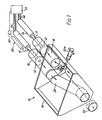
- FIG. 1 shows a slurry pump 10 having two reciprocatable pumping pistons 12 driven by respective hydraulic actuators 14.
- the pistons 12 are reciprocated in respective pumping cylinders 16 which are in communication with the interior of a hopper 18 filled with slurry to be pumped.
- the pistons 12 are reciprocated with opposite phases, so that during each half of the pumping cycle, slurry is drawn into one cylinder 16 and expelled from the other. Slurry expelled from a cylinder 16 is forced along a delivery tube 20 and along a delivery pipe line 22.
- the delivery tube 20 is pivotally mounted at its lower end and its upper end is swung into and out of communication with the cylinders 16 alternately, so as to be always in communication with the cylinder 16 which is expelling slurry.
- the delivery tube 20 is swung by means of a hydraulic actuator 20a comprising double-acting pistons in one or two cylinders. Only one cylinder is shown. A second may be desirable to supplement the swinging force applied to the tube 20, for instance when the tube 20 is large and a larger force is needed to move the tube against the frictional resistance to movement of the tube end.
- each actuator 14 comprises a cylinder 24 and a plunger 26 slidable in and closing the cylinder.
- the plunger 26 is connected to the corresponding piston 12 by a drive rod 15.
- the position of the cylinder is fixed in relation to the hopper 18.
- the chamber between the plunger 26 and the cylinder 24 is partitioned by a hollow cylindrical partition 28 coaxial with the cylinder 24, to define two closed drive chambers 30a, 30b. Sliding movement of the plunger 26 in the cylinder 24 varies the volumes of the chambers 30a, 30b.
- Composite annular seals 32, 33 located in grooves in the partition 28 and the plunger 26 respectively provide sliding seals between the partition 28 and the plunger 26, and between the plunger 26 and the cylinder 24.
- Hydraulic fluid is selectively supplied under pressure to the chambers 30a, 30b through supply ports 34a, 34b. Hydraulic fluid supplied through the port 34a passes along the bore 36 of the partition 28 to act on the face 38 of the plunger 26 and urges the plunger 26 along the axis of the cylinder 24 to the left as seen in Fig. 2.
- Hydraulic pressure supplied through the port 34b acts on the annular faces 40 of the plunger, and also urges the plunger to the left as seen in Fig. 2.
- the actuator 14 further comprises an annular return chamber 42, between the plunger 26 and the cylinder 24.
- the return chamber 42 is sealed from the drive chamber 30b by the seal 33 around the plunger 26.
- a collar 44 is fixed to the cylinder 24, and has grooves in which further seals 46 are located to seal the return chamber 42 from the outside of the cylinder 24.
- Each actuator has a supply port 48 communicating with its return chamber 42.
- the supply ports 48, and hence the return chambers 42 are interconnected by a pipeline 76.
- Fig. 2 also shows a linkage 80 provided between the plunger 26 of one of the actuators and a spool valve 82.
- the function of the spool valve is to control the reciprocation of the plungers 26 as will be described later.
- the linkage 80 comprises a steel rod 84 attached to a yoke 86 by a nut 88.
- the yoke is attached to the drive rod 15, so that the yoke 86 and the rod 84 move with the plunger 26.
- the rod 84 travels inside a tube 90 which is slidable in a mounting 92. Movement of the cube 90 in the mounting 92 is limited by stops 94a,94b mounted on the tube 90.
- the end of the tube 90 away from the mounting 92 is attached to the operating spool 96 of the valve 82 by a shear pin 98.
- Two short springs 100,102 are located around the rod 84, between the stop 94a (which extends a short way into the tube 90) and the yoke 86, and between the stop 94a and a nut 104 on the free end of the rod 84.
- the linkage 80 operates in the following manner.
- the plunger 26 is moving away from the retracted position shown in Fig.2, the rod 84 moves with it, towards the left of that figure.
- the nut 104 makes contact with the spring 102, which transmits a force to the stop 94a to move the tube 90, and hence the spool 96, until the stop 94b abuts the mounting 92.
- a catch within the valve 82 holds the spool in this position.
- the stop 94b abuts the mounting 92 at the end of the plunger stroke, but any overrun is taken up by the spring 102.
- the rod 84 On the return stroke of the plunger, the rod 84 is retracted into the tube 90 until the yoke 86 bears on the spring 100.
- the spring 100 pushes on the stop 94a to move the tube 90 in the mounting 92 until the stop 94a abuts the mounting 92. This movement returns the spool 96 to its original position where it is retained by the catch.
- the spring 100 absorbs any overrun of the plunger 26 during this phase of its movement.
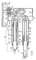
- Fig. 3 shows both actuators 14 and the circuit 52 for supplying hydraulic fluid to them.
- the Figure is schematic for reasons of clarity.
- the circuit 52 comprises a swash plate pump 54 driven by a diesel engine (not shown).
- the pump 54 has a swash plate 56 which causes pistons 58 to reciprocate in a ring of cylinders 60 (only two of which are shown).
- the swash plate is driven by a rotating shaft 61 and the direction in which fluid is pumped between the pipes 66,68 can be reversed by rocking the swash plate 56 on the end of the shaft 61.
- Reversal of the swash plate 56 is effected by an actuator 104 to which pressurised fluid is supplied under the control of the valve 82, from a small pump 62.
- the pump 62 draws fluid from a sump 64.
- the pumping delivery can be varied by changing the angle of the swash plate 56 to its rotation axis, thereby varying the stroke length of the pistons 58, or by changing the throttle setting of the engine driving the pump 54.
- the engine is set to run at a speed to generate optimum power, and the volume delivered by the pump 54 is set by the angle of the swash plate 56. Thereafter, the swash plate position remains the same except for reversal by the actuator 104.
- the pipe 66 and the pipe 68 are both branched and connect the pump 54 to the supply ports 34b of the drive chambers 30b of respective actuators 14, and to one port of a respective three-way valve 70.
- a pipe 72 connects a second port of each valve 70 to the supply port 34a of the drive chamber 30a of one of the actuators 14.
- a pipe 74 connects the third ports of the valves 70 to the sump 64.
- a further pipe 76 connects the return chambers 42 of the actuators 14.
- the valves 70 have two positions. In the first position, shown in Fig. 3, they connect the piping 72 to the piping 74. Thus the chambers 30a of both actuators 14 are vented to the sump 64, while the pump 54 pumps fluid from the drive chamber 30b of one actuator 14 to the equivalent drive chamber 30b of the other actuator 14.
- the valves 70 are provided by two single or one double selector valve controlled by a single, manually operated control indicated at 71.
- valves 70 When the slurry pump 10 is in use, the operator sets the positions of the valves 70 together, by operating the control 71.
- hydraulic pressure acts on the face 40 of the plunger 26 in the actuator shown at the top of the figure.
- the plunger of the upper actuator 14 is driven to the left, and as it moves, hydraulic fluid is expelled from the return chamber 42 of the upper actuator 14.
- the expelled fluid passes along the pipe 76 and enters the return chamber 42 of the lower actuator 14, to retract the plunger of the lower actuator from the extended position shown.
- the plungers are driven with a smaller force by comparison with the situation to be described with reference to Fig. 4 when the valves 70 are in the position shown In Figure 3, because hydraulic pressure bears on the faces 40, but not on the faces 38.
- the valves 70 In order to fully extend a plunger, only the chamber 30b is filled, so that only a relatively small volume of fluid must be provided by the pump 54. Consequently, the plungers move quickly, and for a fixed setting of the pump 54 and the diesel engine driving the pump 54, the situation shown in Fig. 3 results in the pump 10 pumping slurry with a relatively low pumping force, but at a relatively high rate.
- hydraulic fluid acts on the faces 38 as well as acting on the faces 40.
- the plunger 26 is driven with a greater force than when the valves 70 are in the positions shown in Fig. 3.
- the volume of fluid which must be pumped in order fully to extend the plunger is also increased because both drive chambers 30a, 30b are filled.
- the plungers move more slowly in comparison with the arrangement of Fig. 3. Accordingly, the arrangement of Fig. 4 operates the pump 10 to pump with a larger pumping force but at a slower rate.
- the output of the pump 62 may be used additionally for topping up the hydraulic system (including the return chambers) in the event of leakages.
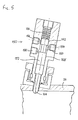
- An alternative linkage for controlling the valve 82 uses pilot valves like the one shown in Fig. 5.
- the pilot valve 150 is mounted on the cylinder 24. For clarity, only a small portion of the cylinder 24 is shown in Fig.5 and a plunger 26 is not shown.
- the valve 150 is a spool valve having a spool 152 and three ports 154, 156, 158. In the position shown, the ports 154 and 158 are in communication around the neck 160 of the spool 152. The land 162 closes the port 156.
- the lower end 164 (as shown in Fig.5) of the spool 152 penetrates the wall of the cylinder 24.
- a spring 166 urges the spool 152 to this position.
- the lower end 164 of the spool 152 is so positioned within the cylinder 24 that the spool 152 will be pressed upwardly to a raised position by the plunger in the cylinder 24, when the plunger reaches the one end of its stroke.
- the land 162 In the raised position of the spool 152, the land 162 is above and clear of the port 156 which communicates with the port 154 around the neck 160. A second land 168 closes the port 158.
- the valve 150 is therefore a two position changeover valve, able to connect the port 154 selectably to the port 156 or the port 158.
- FIG. 6 which is highly schematic, shows how two such valves 150 can be used to control the valve 82 to reverse the direction of drive of the plungers of two actuators.
- the valves 150 are located at opposite ends of the stroke of the plunger 26 in one of the cylinders 24.
- each valve 150 is supplied with pressurised fluid over a line 170.
- the ports 158 are vented over a line 172.
- the ports 154 are connected through a double chack valve 174 to the two position spool valve 82.
- the ports 154 supply pressure to respective ends of the spool of the valve 82, so that pressure supplied through one or other of the ports 154 will change the state of the valve 82 and reverse the plungers 26.
- the double check valve 174 includes a one-way check valve in the line between each of the ports 154 and the valve 82.
- the check valves allow fluid flow from the ports 154 to the valve 82.
- the check valve 174 also includes an over-ride facility which allows pressure from the port 154 of either of the valves 150 to over-ride the check valve in the line from the port 154 of the other valve 150.
- valve 150 at that end of the stroke is operated to move to its other position, in which the port 154 is connected to the pressurised line 170.
- Pressurised fluid passes from the port 156 to the port 154, then through the cheeck valve, finally bearing on the spool of the valve 82 to change the state of the valve 82.
- the check valve between the other valve 150 and the spool valve 82 is overridden so that fluid displaced by the spool can vent through that other valve 150 and over the line 172.
- valve 82 reverses the plungers 26 so that they move away from their end positions.
- the valves 150 revert to the states shown, with both ports 154 vented.
- the spool of the valve 82 is held in position by the check valve 174.
- the other valve 150 is operated to move the spool of the valve 82 back, to reverse the plungers 26 again.
- valves 150 are shown in Figure 6 it respective ends of the stroke of the same plunger. They could be operated at the same end of the stroke of respective plungers.
- the valves 150 could be used to control one or more intermediate valves rather than to control the valve 82 directly.
- the intermediate valves could be used to reverse the supply direction of fluid at a pilot pressure much lover than the pressure of fluid to the actuators 14.
- the pilot pressure would be used to control not only the valve 82, but also other functions. For instance, a delay could be introduced between the operation of the valves 150 and the change of the valve 82, to allow the tube 20 to be moved to the other pumping cylinder 16 before the pistons 12 recommence movement.
- the European patent application referred to above describes a clamping arrangement for sealing the tube around the openings of the cylinders 16. This sealing clamping pressure would be reduced to allow the tube 20 to swing, in sealing contact with a flat surface and then be reapplied. This sequence of operations would take place during the delay and be triggered by the changeover of the valve controlled by the valves 150.
- Figure 6 also shows lines 176 and 178 connected to respective ends of the spool valve controlled by the valves 150. Pressure on the lines 176, 178 is controlled by a manually operable valve, not shown, which allows the operation of the valves 150 to be overridden, to reverse the plungers in mid-stroke.
Abstract
Description
- The present invention relates to a pumping apparatus in which a pair of pumping pistons in respective cylinders are driven with opposite phases to draw material in from a hopper and expel into a pipe.
- EP-A-0085521 describes such a pump which is intended for pumping concrete or other types of slurry from a hopper into a pipeline. Two pumping pistons in respective cylinders are driven with opposite phases to alternately draw slurry from the hopper and force it along the pipeline. The pistons are driven by respective hydraulic actuators which comprise double-acting pistons slidable in cylinders.
- DE-A-1653478 describes another example of a pump in which two pumping pistons in respective cylinders are driven with opposite phases.
- According to the present invention there is provided a pumping apparatus, comprising first and second variable-volume pumping cylinders (16), first and second pumping members (12) reciprocal within the first and second pumping cylinders, respectively, to vary the volume thereof, the pumping cylinders each having an inlet for the introduction of material to be pumped and an outlet for the delivery of material from the pumping cylinder, first and second actuators (14) coupled to the first and second pumping members respectively, and operable to reciprocate the pumping members, the first and second actuators driving the first and second pumping members with mutually opposite phases, a hydraulic fluid sump (64) and pump (54) connected to the pump for the supply of hydraulic pressure fluid to each actuator, wherein each actuator (14) comprises an actuator cylinder (24), a hollow plunger (26) located within the cylinder (24), a hollow cylindrical partition (28) fixed with respect to the cylinder (24) and arranged within the plunger (26), the partition (28) cooperating with the plunger (26) and the cylinder (24) to define first and second drive chambers (30a, 30b) having different working areas, the first drive chamber being defined by the interior of the hollow cylindrical portion and the interior of the plunger and the second drive chamber being defined by the exterior of the partition and the interior of the actuator cylinder (24) and the end of the plunger remote from the pumping cylinder, the plunger (26) being slidable in the cylinder bore and with respect to the said hollow cylindrical partition (28) to vary the volumes of said drive chambers (30a, 30b), the first and second valves (70) being connected between the sump (64) and the first drive chambers of the first and second actuators (14) respectively to allow pressure fluid to be pumped directly to the first and second drive chambers respectively, each valve being operable to shut off flow of hydraulic fluid from the supply to one of the drive chambers of the associated actuator (14) to determine the pumping force transmitted to the associated pumping member (12), said first and second valves comprising two single or one double selector valve, and a manual valve control (71) for controlling operation of the first and second valves so that, at any given time, the valves are in the same position and pressure fluid is supplied on alternate strokes to corresponding drive chambers in the first and second actuators.
- The ability to select the drive chambers to which hydraulic pressure is supplied enables the force provided by the actuator to be selected while the hydraulic pressure supplied to the actuators remains constant. Thus, in the pump embodying the invention, the pressure at which material is pumped can be selected without changing the hydraulic supply pressure. This is not possible in the known pumps described above, and consequently those pumps cannot pump any particular material through more than a fixed maximum height. The maximum height through which a material may be pumped by a pump embodying the present invention can be changed by changing the selection of chambers supplied with pressurised fluid. Accompanying a change in the selection, there is a change in the pumping speed. Thus, when the pump is required to pump to a greater height, a high pumping pressure can be selected (with correspondingly reduced delivery flow) whereas when pumping to a lower height is required, a lower pumping pressure can be selected so as to increase the pumping speed and delivery flow. Regardless of these changes, the means supplying hydraulic fluid to the actuators can be operated to supply constant power at their most efficient setting.
- A temporary increase in pumping pressure may be used if material is being pumped through a pipeline and the pipeline becomes blocked. The sudden increase in pumping pressure which is obtained by changing the selection of drive chambers in use may be sufficient to clear the blockage, thereby avoiding the need to turn off the pump and manually find and clear the blockage.
- An embodiment of the invention will now be described by way of example with reference to the accompanying drawings in which:
- Fig. 1 is a schematic perspective view of the pump;
- Fig. 2 is an axial sectional view of the actuator driving one of the pumping members of the pump of Fig. 1;
- Fig. 3 is a diagram showing both actuators of the pump of Fig. 1, connected to the associated hydraulic circuit in the condition arranged for low pressure pumping;
- Fig. 4 is a diagram like Fig. 3, hut in the condition for high pressure pumping; and
- Fig.5 and 6 show a valve and a circuit incorporating the valve for reversing the plungers of the actuators.
- Figure 1 shows a slurry pump 10 having two
reciprocatable pumping pistons 12 driven by respectivehydraulic actuators 14. Thepistons 12 are reciprocated inrespective pumping cylinders 16 which are in communication with the interior of ahopper 18 filled with slurry to be pumped. Thepistons 12 are reciprocated with opposite phases, so that during each half of the pumping cycle, slurry is drawn into onecylinder 16 and expelled from the other. Slurry expelled from acylinder 16 is forced along adelivery tube 20 and along adelivery pipe line 22. Thedelivery tube 20 is pivotally mounted at its lower end and its upper end is swung into and out of communication with thecylinders 16 alternately, so as to be always in communication with thecylinder 16 which is expelling slurry. Thedelivery tube 20 is swung by means of ahydraulic actuator 20a comprising double-acting pistons in one or two cylinders. Only one cylinder is shown. A second may be desirable to supplement the swinging force applied to thetube 20, for instance when thetube 20 is large and a larger force is needed to move the tube against the frictional resistance to movement of the tube end. - The structure of each
actuator 14 is shown in Fig. 2. Eachactuator 14 comprises acylinder 24 and aplunger 26 slidable in and closing the cylinder. Theplunger 26 is connected to thecorresponding piston 12 by adrive rod 15. The position of the cylinder is fixed in relation to thehopper 18. - The chamber between the
plunger 26 and thecylinder 24 is partitioned by a hollowcylindrical partition 28 coaxial with thecylinder 24, to define two closeddrive chambers plunger 26 in thecylinder 24 varies the volumes of thechambers annular seals partition 28 and theplunger 26 respectively provide sliding seals between thepartition 28 and theplunger 26, and between theplunger 26 and thecylinder 24. - Hydraulic fluid is selectively supplied under pressure to the
chambers supply ports 34a, 34b. Hydraulic fluid supplied through theport 34a passes along thebore 36 of thepartition 28 to act on theface 38 of theplunger 26 and urges theplunger 26 along the axis of thecylinder 24 to the left as seen in Fig. 2. - Hydraulic pressure supplied through the port 34b acts on the
annular faces 40 of the plunger, and also urges the plunger to the left as seen in Fig. 2. - The
actuator 14 further comprises anannular return chamber 42, between theplunger 26 and thecylinder 24. Thereturn chamber 42 is sealed from thedrive chamber 30b by theseal 33 around theplunger 26. Acollar 44 is fixed to thecylinder 24, and has grooves in whichfurther seals 46 are located to seal thereturn chamber 42 from the outside of thecylinder 24. Each actuator has asupply port 48 communicating with itsreturn chamber 42. Thesupply ports 48, and hence thereturn chambers 42 are interconnected by apipeline 76. When theplunger 26 of oneactuator 14 is being extended, fluid is driven out of thereturn chamber 42 of that actuator and into thereturn chamber 42 of theother actuator 14 where it acts on ashoulder 50 on theplunger 26 to drive the plunger to the fully retracted position shown in Fig. 2. Accordingly, the plungers move with opposite phases. - Fig. 2 also shows a
linkage 80 provided between theplunger 26 of one of the actuators and aspool valve 82. The function of the spool valve is to control the reciprocation of theplungers 26 as will be described later. - The
linkage 80 comprises asteel rod 84 attached to ayoke 86 by anut 88. The yoke is attached to thedrive rod 15, so that theyoke 86 and therod 84 move with theplunger 26. Therod 84 travels inside atube 90 which is slidable in amounting 92. Movement of thecube 90 in themounting 92 is limited bystops 94a,94b mounted on thetube 90. The end of thetube 90 away from themounting 92 is attached to theoperating spool 96 of thevalve 82 by ashear pin 98. - Two short springs 100,102 are located around the
rod 84, between thestop 94a (which extends a short way into the tube 90) and theyoke 86, and between thestop 94a and anut 104 on the free end of therod 84. - The
linkage 80 operates in the following manner. When theplunger 26 is moving away from the retracted position shown in Fig.2, therod 84 moves with it, towards the left of that figure. Eventually, near the end of the stroke, thenut 104 makes contact with thespring 102, which transmits a force to thestop 94a to move thetube 90, and hence thespool 96, until the stop 94b abuts themounting 92. A catch within thevalve 82 holds the spool in this position. Ideally, the stop 94b abuts themounting 92 at the end of the plunger stroke, but any overrun is taken up by thespring 102. On the return stroke of the plunger, therod 84 is retracted into thetube 90 until theyoke 86 bears on thespring 100. Thespring 100 pushes on thestop 94a to move thetube 90 in themounting 92 until thestop 94a abuts themounting 92. This movement returns thespool 96 to its original position where it is retained by the catch. Thespring 100 absorbs any overrun of theplunger 26 during this phase of its movement. - Fig. 3 shows both
actuators 14 and thecircuit 52 for supplying hydraulic fluid to them. The Figure is schematic for reasons of clarity. In particular, thelinkage 80 is shown simply, in broken lines. Thecircuit 52 comprises aswash plate pump 54 driven by a diesel engine (not shown). Thepump 54 has aswash plate 56 which causespistons 58 to reciprocate in a ring of cylinders 60 (only two of which are shown). The swash plate is driven by a rotatingshaft 61 and the direction in which fluid is pumped between thepipes swash plate 56 on the end of theshaft 61. Reversal of theswash plate 56 is effected by anactuator 104 to which pressurised fluid is supplied under the control of thevalve 82, from asmall pump 62. Thepump 62 draws fluid from asump 64. - The pumping delivery can be varied by changing the angle of the
swash plate 56 to its rotation axis, thereby varying the stroke length of thepistons 58, or by changing the throttle setting of the engine driving thepump 54. The engine is set to run at a speed to generate optimum power, and the volume delivered by thepump 54 is set by the angle of theswash plate 56. Thereafter, the swash plate position remains the same except for reversal by theactuator 104. - The
pipe 66 and thepipe 68 are both branched and connect thepump 54 to the supply ports 34b of thedrive chambers 30b ofrespective actuators 14, and to one port of a respective three-way valve 70. Apipe 72 connects a second port of eachvalve 70 to thesupply port 34a of thedrive chamber 30a of one of theactuators 14. Apipe 74 connects the third ports of thevalves 70 to thesump 64. Afurther pipe 76 connects thereturn chambers 42 of theactuators 14. - The
valves 70 have two positions. In the first position, shown in Fig. 3, they connect the piping 72 to thepiping 74. Thus thechambers 30a of bothactuators 14 are vented to thesump 64, while thepump 54 pumps fluid from thedrive chamber 30b of oneactuator 14 to theequivalent drive chamber 30b of theother actuator 14. - In the second position, shown in Fig. 4, the
pipes pipes 72. The pump now supplies hydraulic fluid to both drivechambers chambers other actuator 14. - The
valves 70 are provided by two single or one double selector valve controlled by a single, manually operated control indicated at 71. - When the slurry pump 10 is in use, the operator sets the positions of the
valves 70 together, by operating thecontrol 71. When thevalves 70 are in the positions shown in Fig. 3, and with the actuators in the positions shown there, hydraulic pressure acts on theface 40 of theplunger 26 in the actuator shown at the top of the figure. The plunger of theupper actuator 14 is driven to the left, and as it moves, hydraulic fluid is expelled from thereturn chamber 42 of theupper actuator 14. The expelled fluid passes along thepipe 76 and enters thereturn chamber 42 of thelower actuator 14, to retract the plunger of the lower actuator from the extended position shown. - Fluid continues to pass in this way until the plunger of the lower actuator is fully retracted and the plunger of the upper actuator is fully extended. At this point, the
valve 82 controlling the swash plate moves to its other position, and so reverses the swash plate angle. The direction in which thepump 54 is pumping, and the directions of movement of the plungers then reverse. - The plungers are driven with a smaller force by comparison with the situation to be described with reference to Fig. 4 when the
valves 70 are in the position shown In Figure 3, because hydraulic pressure bears on thefaces 40, but not on thefaces 38. In order to fully extend a plunger, only thechamber 30b is filled, so that only a relatively small volume of fluid must be provided by thepump 54. Consequently, the plungers move quickly, and for a fixed setting of thepump 54 and the diesel engine driving thepump 54, the situation shown in Fig. 3 results in the pump 10 pumping slurry with a relatively low pumping force, but at a relatively high rate. When thevalves 70 are in the positions shown in Fig. 4, hydraulic fluid acts on thefaces 38 as well as acting on thefaces 40. For the same setting of thepump 54 and of the engine driving it, that is, for the same fluid supply pressure, theplunger 26 is driven with a greater force than when thevalves 70 are in the positions shown in Fig. 3. However the volume of fluid which must be pumped in order fully to extend the plunger is also increased because both drivechambers - In the arrangement of Fig. 4, as in the arrangement of Fig. 3, one
plunger 26 is driven out until it is fully extended, whereupon the pumping direction of thepump 54 is reversed, to extend theother plunger 26. As each plunger extends, it expels fluid from the correspondingreturn chamber 42 into theother return chamber 42 to retract theother plunger 26. - The output of the
pump 62 may be used additionally for topping up the hydraulic system (including the return chambers) in the event of leakages. - An alternative linkage for controlling the
valve 82 uses pilot valves like the one shown in Fig. 5. Thepilot valve 150 is mounted on thecylinder 24. For clarity, only a small portion of thecylinder 24 is shown in Fig.5 and aplunger 26 is not shown. - The
valve 150 is a spool valve having aspool 152 and threeports ports neck 160 of thespool 152. Theland 162 closes theport 156. - The lower end 164 (as shown in Fig.5) of the
spool 152 penetrates the wall of thecylinder 24. Aspring 166 urges thespool 152 to this position. Thelower end 164 of thespool 152 is so positioned within thecylinder 24 that thespool 152 will be pressed upwardly to a raised position by the plunger in thecylinder 24, when the plunger reaches the one end of its stroke. - In the raised position of the
spool 152, theland 162 is above and clear of theport 156 which communicates with theport 154 around theneck 160. A second land 168 closes theport 158. - The
valve 150 is therefore a two position changeover valve, able to connect theport 154 selectably to theport 156 or theport 158. - Figure 6, which is highly schematic, shows how two
such valves 150 can be used to control thevalve 82 to reverse the direction of drive of the plungers of two actuators. Thevalves 150 are located at opposite ends of the stroke of theplunger 26 in one of thecylinders 24. - The
port 156 of eachvalve 150 is supplied with pressurised fluid over aline 170. Theports 158 are vented over aline 172. Theports 154 are connected through adouble chack valve 174 to the twoposition spool valve 82. Theports 154 supply pressure to respective ends of the spool of thevalve 82, so that pressure supplied through one or other of theports 154 will change the state of thevalve 82 and reverse theplungers 26. - The
double check valve 174 includes a one-way check valve in the line between each of theports 154 and thevalve 82. The check valves allow fluid flow from theports 154 to thevalve 82. Thecheck valve 174 also includes an over-ride facility which allows pressure from theport 154 of either of thevalves 150 to over-ride the check valve in the line from theport 154 of theother valve 150. - The circuit of Figure 6 operates in the following way. In mid-stroke of the
pistons 26, bothvalves 150 will be in the position shown in Figures 5 and 6. Theports 154 are vented over theline 172. - When the
plunger 26 reaches the end of its stroke, thevalve 150 at that end of the stroke is operated to move to its other position, in which theport 154 is connected to the pressurisedline 170. Pressurised fluid passes from theport 156 to theport 154, then through the cheeck valve, finally bearing on the spool of thevalve 82 to change the state of thevalve 82. The check valve between theother valve 150 and thespool valve 82 is overridden so that fluid displaced by the spool can vent through thatother valve 150 and over theline 172. - The change of the state of the
valve 82 reverses theplungers 26 so that they move away from their end positions. Thevalves 150 revert to the states shown, with bothports 154 vented. The spool of thevalve 82 is held in position by thecheck valve 174. - When the plungers reach the other end of their strokes, the
other valve 150 is operated to move the spool of thevalve 82 back, to reverse theplungers 26 again. - The
valves 150 are shown in Figure 6 it respective ends of the stroke of the same plunger. They could be operated at the same end of the stroke of respective plungers. - The
valves 150 could be used to control one or more intermediate valves rather than to control thevalve 82 directly. The intermediate valves could be used to reverse the supply direction of fluid at a pilot pressure much lover than the pressure of fluid to theactuators 14. The pilot pressure would be used to control not only thevalve 82, but also other functions. For instance, a delay could be introduced between the operation of thevalves 150 and the change of thevalve 82, to allow thetube 20 to be moved to theother pumping cylinder 16 before thepistons 12 recommence movement. The European patent application referred to above describes a clamping arrangement for sealing the tube around the openings of thecylinders 16. This sealing clamping pressure would be reduced to allow thetube 20 to swing, in sealing contact with a flat surface and then be reapplied. This sequence of operations would take place during the delay and be triggered by the changeover of the valve controlled by thevalves 150. - Figure 6 also shows lines 176 and 178 connected to respective ends of the spool valve controlled by the
valves 150. Pressure on the lines 176, 178 is controlled by a manually operable valve, not shown, which allows the operation of thevalves 150 to be overridden, to reverse the plungers in mid-stroke.
Claims (5)
- A pumping apparatus, comprising first and second variable-volume pumping cylinders (16), first and second pumping members (12) reciprocal within the first and second pumping cylinders, respectively, to vary the volume thereof, the pumping cylinders each having an inlet for the introduction of material to be pumped and an outlet for the delivery of material from the pumping cylinder, first and second actuators (14) coupled to the first and second pumping members respectively, and operable to reciprocate the pumping members, the first and second actuators driving the first and second pumping members with mutually opposite phases, a hydraulic fluid sump (64) and pump (54) connected to the pump for the supply of hydraulic pressure fluid to each actuator, wherein each actuator (14) comprises an actuator cylinder (24), a hollow plunger (26) located within the cylinder (24), a hollow cylindrical partition (28) fixed with respect to the cylinder (24) and arranged within the plunger (26), the partition (28) cooperating with the plunger (26) and the cylinder (24) to define first and second drive chambers (30a, 30b) having different working areas, the first drive chamber being defined by the interior of the hollow cylindrical portion and the interior of the plunger and the second drive chamber being defined by the exterior of the partition and the interior of the actuator cylinder (24) and the end of the plunger remote from the pumping cylinder, the plunger (26) being slidable in the cylinder bore and with respect to the said hollow cylindrical partition (28) to vary the volumes of said drive chambers (30a, 30b), the first and second valves (70) being connected between the sump (64) and the first drive chambers of the first and second actuators (14) respectively to allow pressure fluid to be pumped directly to the first and second drive chambers respectively, each valve being operable to shut off flow of hydraulic fluid from the supply to one of the drive chambers of the associated actuator (14) to determine the pumping force transmitted to the associated pumping member (12), said first and second valves comprising two single or one double selector valve, and a manual valve control (71) for controlling operation of the first and second valves so that, at any given time, the valves are in the same position and pressure fluid is supplied on alternate strokes to corresponding drive chambers in the first and second actuators.
- Apparatus according to claim 1, wherein each actuator has a return chamber (42) between plunger (26) and the cylinder (24) characterised in that fluid pressure in the return chamber of one actuator drives the plunger in the other actuator with respect to its corresponding cylinder so as to reduce the volume of the drive chambers (30A, 30B) defined by the corresponding plunger and cylinder; and by fluid supply means interconnecting the return chambers of the first and second actuators.
- Apparatus according to Claim 2 characterised by reversing means (150, 174, 82) operable to detect the plunger at each end of its stroke and to divert supplied hydraulic fluid to the drive chambers or their return chamber in order to reverse the plunger.
- Apparatus according to Claim 3, characterised in that the reversing means comprises a further valve (82) having first and second states in which hydraulic fluid is diverted, respectively, to one or more of the drive chamber (30A, 30B) and to the return chamber (42) and means (150, 174) operated by the plunger at the ends of its stroke and operable to change the state of the further valve.
- An actuator according to Claim 4, characterised in that the means (150, 174) operated by the plunger comprise two pilot valves (150) opened by the plunger at respective ends of its stroke to supply pressurised fluid to change the state of the second valve (82).
Priority Applications (1)
| Application Number | Priority Date | Filing Date | Title |
|---|---|---|---|
| AT86300961T ATE72882T1 (en) | 1985-02-12 | 1986-02-12 | DRIVE FOR SLUDGE PISTON PUMP. |
Applications Claiming Priority (2)
| Application Number | Priority Date | Filing Date | Title |
|---|---|---|---|
| GB858503501A GB8503501D0 (en) | 1985-02-12 | 1985-02-12 | Reciprocatory pumps |
| GB8503501 | 1985-02-12 |
Publications (3)
| Publication Number | Publication Date |
|---|---|
| EP0197632A2 EP0197632A2 (en) | 1986-10-15 |
| EP0197632A3 EP0197632A3 (en) | 1987-08-19 |
| EP0197632B1 true EP0197632B1 (en) | 1992-02-26 |
Family
ID=10574304
Family Applications (1)
| Application Number | Title | Priority Date | Filing Date |
|---|---|---|---|
| EP86300961A Expired - Lifetime EP0197632B1 (en) | 1985-02-12 | 1986-02-12 | Actuator for a reciprocating slurry pump |
Country Status (5)
| Country | Link |
|---|---|
| US (1) | US4790728A (en) |
| EP (1) | EP0197632B1 (en) |
| AT (1) | ATE72882T1 (en) |
| DE (1) | DE3683947D1 (en) |
| GB (1) | GB8503501D0 (en) |
Families Citing this family (19)
| Publication number | Priority date | Publication date | Assignee | Title |
|---|---|---|---|---|
| US5106272A (en) * | 1990-10-10 | 1992-04-21 | Schwing America, Inc. | Sludge flow measuring system |
| US5388965A (en) * | 1990-10-10 | 1995-02-14 | Friedrich Wilhelm Schwing Gmbh | Sludge pump with monitoring system |
| US5257912A (en) * | 1990-10-10 | 1993-11-02 | Schwing America, Inc. | Sludge flow measuring system |
| DE3814824A1 (en) * | 1988-05-02 | 1989-11-16 | Putzmeister Maschf | CONTROL ARRANGEMENT FOR A TWO-CYLINDER FUEL PUMP |
| US5660532A (en) * | 1988-05-02 | 1997-08-26 | Institut Francais Du Petrole | Multiphase piston-type pumping system and applications of this system |
| JP2671216B2 (en) * | 1988-06-02 | 1997-10-29 | トウフク株式会社 | Slurry pumping equipment |
| DE3910120A1 (en) * | 1989-03-29 | 1990-10-04 | Putzmeister Maschf | CONTROL ARRANGEMENT FOR A TWO-CYLINDER FUEL PUMP |
| US5332366A (en) * | 1993-01-22 | 1994-07-26 | Schwing America, Inc. | Concrete pump monitoring system |
| US5330327A (en) * | 1993-04-27 | 1994-07-19 | Schwing America, Inc. | Transfer tube material flow management |
| JP3371687B2 (en) * | 1996-06-11 | 2003-01-27 | 株式会社スリーボンド | Dispensing method |
| GB9900286D0 (en) * | 1999-01-08 | 1999-02-24 | Devpro Limited | Pump |
| US20060193738A1 (en) * | 2005-02-26 | 2006-08-31 | Friedrich Schwing | Pump apparatus and method for continuously conveying a viscous material |
| DE102005024174A1 (en) * | 2005-05-23 | 2006-12-07 | Schwing, Friedrich, Dipl.-Ing. | Method for controlling a pumping device for conveying mushy masses and controlling a pumping device for conveying mushy masses |
| WO2009076429A2 (en) | 2007-12-10 | 2009-06-18 | Medrad, Inc. | Continuous fluid delivery system and method |
| US8231362B2 (en) * | 2009-02-10 | 2012-07-31 | Innoventor Renewable Power, Inc. | Multi-chambered pump |
| ITTO20090682A1 (en) * | 2009-09-03 | 2011-03-04 | Drillmec Spa | HYDRAULICALLY OPERATED CEMENT PUMP. |
| US20140023530A1 (en) * | 2012-01-05 | 2014-01-23 | Michael E. Frey | Piston pump for liquefied gas |
| US9765768B2 (en) | 2014-01-15 | 2017-09-19 | Francis Wayne Priddy | Concrete pump system and method |
| US10507319B2 (en) | 2015-01-09 | 2019-12-17 | Bayer Healthcare Llc | Multiple fluid delivery system with multi-use disposable set and features thereof |
Citations (1)
| Publication number | Priority date | Publication date | Assignee | Title |
|---|---|---|---|---|
| EP0085521A1 (en) * | 1982-01-22 | 1983-08-10 | Hydroseal Concrete Pumps Limited | Slurry pump |
Family Cites Families (20)
| Publication number | Priority date | Publication date | Assignee | Title |
|---|---|---|---|---|
| US1667138A (en) * | 1925-04-06 | 1928-04-24 | Frank S Barks | Valve mechanism |
| US1910019A (en) * | 1929-09-18 | 1933-05-23 | Kelly Orin | Fluid-pressure motor |
| US2596471A (en) * | 1950-01-21 | 1952-05-13 | Richard M Densmore | Variable-stop hydraulic system |
| US3106257A (en) * | 1960-08-22 | 1963-10-08 | Vernon L Helm | Rock core drills |
| US3205906A (en) * | 1963-07-16 | 1965-09-14 | Case Co J I | Pump and valve assembly |
| US3279382A (en) * | 1964-04-14 | 1966-10-18 | Royal Industries | Pump |
| US3335642A (en) * | 1965-01-08 | 1967-08-15 | Borje O Rosaen | Cylinder construction |
| US3353352A (en) * | 1966-01-11 | 1967-11-21 | Caterpillar Tractor Co | Load balancing system for hydraulic jack |
| DE1653478A1 (en) * | 1966-06-16 | 1971-03-11 | Fauner Anneliese | concrete pump |
| US3398693A (en) * | 1966-08-01 | 1968-08-27 | Danken Inc | Concrete pumping apparatus |
| US3635125A (en) * | 1969-03-21 | 1972-01-18 | Nordson Corp | Double-acting hydraulic pump and air motor therefor |
| US3667869A (en) * | 1970-03-04 | 1972-06-06 | Karl Schlecht | Dual cylinder-concrete pump |
| US3744375A (en) * | 1970-06-26 | 1973-07-10 | P Kubik | Fluid system |
| US3682575A (en) * | 1970-12-10 | 1972-08-08 | Karl Guddal | Concrete pump |
| US3774696A (en) * | 1971-10-13 | 1973-11-27 | Case Co J I | Pitch-tilt hydraulic circuits for dozer blades |
| US3959967A (en) * | 1975-06-06 | 1976-06-01 | Centre D'etudes Et De Realisations Industrielles De L'atlantique C.E.R.I.A. | Reciprocating apparatus particularly for pump unit |
| US4241641A (en) * | 1978-08-14 | 1980-12-30 | Reinert Gerald H | Pilot assembly for hydraulic pumps |
| US4611973A (en) * | 1981-10-08 | 1986-09-16 | P & B Industries | Pumping system and method of operating the same |
| DE3243738A1 (en) * | 1982-11-26 | 1984-05-30 | Karl Dipl.-Ing. 7000 Stuttgart Schlecht | Hydraulic reversal for two-cylinder piston pump |
| JPS59185881A (en) * | 1983-04-08 | 1984-10-22 | Taiheiyo Kinzoku Kk | Hydraulic control unit for reciprocating double-row cylinder type positive displacement pump |
-
1985
- 1985-02-12 GB GB858503501A patent/GB8503501D0/en active Pending
- 1985-11-25 US US06/801,531 patent/US4790728A/en not_active Expired - Fee Related
-
1986
- 1986-02-12 AT AT86300961T patent/ATE72882T1/en active
- 1986-02-12 DE DE8686300961T patent/DE3683947D1/en not_active Expired - Fee Related
- 1986-02-12 EP EP86300961A patent/EP0197632B1/en not_active Expired - Lifetime
Patent Citations (1)
| Publication number | Priority date | Publication date | Assignee | Title |
|---|---|---|---|---|
| EP0085521A1 (en) * | 1982-01-22 | 1983-08-10 | Hydroseal Concrete Pumps Limited | Slurry pump |
Also Published As
| Publication number | Publication date |
|---|---|
| EP0197632A3 (en) | 1987-08-19 |
| ATE72882T1 (en) | 1992-03-15 |
| GB8503501D0 (en) | 1985-03-13 |
| DE3683947D1 (en) | 1992-04-02 |
| EP0197632A2 (en) | 1986-10-15 |
| US4790728A (en) | 1988-12-13 |
Similar Documents
| Publication | Publication Date | Title |
|---|---|---|
| EP0197632B1 (en) | Actuator for a reciprocating slurry pump | |
| US4780064A (en) | Pump assembly and its method of operation | |
| US6210131B1 (en) | Fluid intensifier having a double acting power chamber with interconnected signal rods | |
| US4490096A (en) | Pump system for liquid/solid materials with balanced output | |
| EP0422745B1 (en) | Concrete-pumping device | |
| GB1068863A (en) | Improvements in or relating to reciprocating pumps | |
| US6769884B2 (en) | Hydraulic drive system for piston pumps | |
| GB1420424A (en) | High pressure fluid intensifier and method | |
| EP3232057B1 (en) | Method for transmitting or conveying fluid or semi-fluid materials by means of a double piston pump and double piston pump therefor | |
| CA1190091A (en) | Synchronized mixing pump | |
| CA1318217C (en) | Pumping system | |
| EP0118497B1 (en) | Hydraulically actuated bore and well pump | |
| GB1319888A (en) | Single or double acting pump for discharging a liquid or a viscous substance | |
| US4145884A (en) | Reversible power transmission | |
| US4696221A (en) | Dual valve control for double action hydraulic cylinder | |
| US4571939A (en) | Hydraulic well pump | |
| US3476057A (en) | Aggregate pumping apparatus | |
| GB1291331A (en) | Concrete pump assemblies | |
| US2286358A (en) | Hydraulic control for variable delivery pumps | |
| US3779671A (en) | Hydraulic driven piston pump | |
| US3718409A (en) | Reciprocating pump control system | |
| EP0100149A1 (en) | Diaphragm pumps | |
| JPS6214715B2 (en) | ||
| US3945768A (en) | Fluid motor drives pump having an active inlet valve | |
| WO2015087337A1 (en) | Hydraulically operated but mechanically driven & mechanically reversed simple concrete pump |
Legal Events
| Date | Code | Title | Description |
|---|---|---|---|
| PUAI | Public reference made under article 153(3) epc to a published international application that has entered the european phase |
Free format text: ORIGINAL CODE: 0009012 |
|
| AK | Designated contracting states |
Kind code of ref document: A2 Designated state(s): AT BE CH DE FR GB IT LI NL SE |
|
| PUAL | Search report despatched |
Free format text: ORIGINAL CODE: 0009013 |
|
| AK | Designated contracting states |
Kind code of ref document: A3 Designated state(s): AT BE CH DE FR GB IT LI NL SE |
|
| 17P | Request for examination filed |
Effective date: 19880219 |
|
| RAP1 | Party data changed (applicant data changed or rights of an application transferred) |
Owner name: HYDROSEAL CONCRETE PUMPS LIMITED |
|
| RAP3 | Party data changed (applicant data changed or rights of an application transferred) |
Owner name: HYDROSEAL CONCRETE PUMPS LIMITED |
|
| 17Q | First examination report despatched |
Effective date: 19880706 |
|
| GRAA | (expected) grant |
Free format text: ORIGINAL CODE: 0009210 |
|
| ITF | It: translation for a ep patent filed |
Owner name: BARZANO' E ZANARDO MILANO S.P.A. |
|
| AK | Designated contracting states |
Kind code of ref document: B1 Designated state(s): AT BE CH DE FR GB IT LI NL SE |
|
| PG25 | Lapsed in a contracting state [announced via postgrant information from national office to epo] |
Ref country code: SE Effective date: 19920226 Ref country code: NL Effective date: 19920226 Ref country code: LI Effective date: 19920226 Ref country code: CH Effective date: 19920226 Ref country code: BE Effective date: 19920226 Ref country code: AT Effective date: 19920226 |
|
| REF | Corresponds to: |
Ref document number: 72882 Country of ref document: AT Date of ref document: 19920315 Kind code of ref document: T |
|
| REF | Corresponds to: |
Ref document number: 3683947 Country of ref document: DE Date of ref document: 19920402 |
|
| REG | Reference to a national code |
Ref country code: CH Ref legal event code: PL |
|
| EN | Fr: translation not filed | ||
| PG25 | Lapsed in a contracting state [announced via postgrant information from national office to epo] |
Ref country code: FR Effective date: 19920717 |
|
| NLV1 | Nl: lapsed or annulled due to failure to fulfill the requirements of art. 29p and 29m of the patents act | ||
| PLBE | No opposition filed within time limit |
Free format text: ORIGINAL CODE: 0009261 |
|
| STAA | Information on the status of an ep patent application or granted ep patent |
Free format text: STATUS: NO OPPOSITION FILED WITHIN TIME LIMIT |
|
| PG25 | Lapsed in a contracting state [announced via postgrant information from national office to epo] |
Ref country code: GB Effective date: 19930212 |
|
| 26N | No opposition filed | ||
| GBPC | Gb: european patent ceased through non-payment of renewal fee |
Effective date: 19930212 |
|
| PG25 | Lapsed in a contracting state [announced via postgrant information from national office to epo] |
Ref country code: DE Effective date: 19931103 |
|
| REG | Reference to a national code |
Ref country code: FR Ref legal event code: ST |
|
| PG25 | Lapsed in a contracting state [announced via postgrant information from national office to epo] |
Ref country code: IT Free format text: LAPSE BECAUSE OF NON-PAYMENT OF DUE FEES;WARNING: LAPSES OF ITALIAN PATENTS WITH EFFECTIVE DATE BEFORE 2007 MAY HAVE OCCURRED AT ANY TIME BEFORE 2007. THE CORRECT EFFECTIVE DATE MAY BE DIFFERENT FROM THE ONE RECORDED. Effective date: 20050212 |