EP3232052B1 - Éolienne - Google Patents
Éolienne Download PDFInfo
- Publication number
- EP3232052B1 EP3232052B1 EP17165229.0A EP17165229A EP3232052B1 EP 3232052 B1 EP3232052 B1 EP 3232052B1 EP 17165229 A EP17165229 A EP 17165229A EP 3232052 B1 EP3232052 B1 EP 3232052B1
- Authority
- EP
- European Patent Office
- Prior art keywords
- rotary transformer
- nacelle
- tower
- primary
- converter
- Prior art date
- Legal status (The legal status is an assumption and is not a legal conclusion. Google has not performed a legal analysis and makes no representation as to the accuracy of the status listed.)
- Active
Links
- 230000005540 biological transmission Effects 0.000 claims description 28
- 238000000034 method Methods 0.000 claims description 4
- 238000004804 winding Methods 0.000 claims description 2
- 238000009434 installation Methods 0.000 claims 11
- 230000009466 transformation Effects 0.000 claims 1
- 238000004891 communication Methods 0.000 description 3
- 239000004020 conductor Substances 0.000 description 3
- 230000005611 electricity Effects 0.000 description 3
- 208000012886 Vertigo Diseases 0.000 description 2
- 230000015572 biosynthetic process Effects 0.000 description 2
- 238000000605 extraction Methods 0.000 description 2
- 238000006243 chemical reaction Methods 0.000 description 1
- 230000001419 dependent effect Effects 0.000 description 1
- 230000009977 dual effect Effects 0.000 description 1
- 230000006698 induction Effects 0.000 description 1
- 230000001939 inductive effect Effects 0.000 description 1
Images


Classifications
-
- F—MECHANICAL ENGINEERING; LIGHTING; HEATING; WEAPONS; BLASTING
- F03—MACHINES OR ENGINES FOR LIQUIDS; WIND, SPRING, OR WEIGHT MOTORS; PRODUCING MECHANICAL POWER OR A REACTIVE PROPULSIVE THRUST, NOT OTHERWISE PROVIDED FOR
- F03D—WIND MOTORS
- F03D9/00—Adaptations of wind motors for special use; Combinations of wind motors with apparatus driven thereby; Wind motors specially adapted for installation in particular locations
- F03D9/20—Wind motors characterised by the driven apparatus
- F03D9/25—Wind motors characterised by the driven apparatus the apparatus being an electrical generator
- F03D9/255—Wind motors characterised by the driven apparatus the apparatus being an electrical generator connected to electrical distribution networks; Arrangements therefor
-
- F—MECHANICAL ENGINEERING; LIGHTING; HEATING; WEAPONS; BLASTING
- F03—MACHINES OR ENGINES FOR LIQUIDS; WIND, SPRING, OR WEIGHT MOTORS; PRODUCING MECHANICAL POWER OR A REACTIVE PROPULSIVE THRUST, NOT OTHERWISE PROVIDED FOR
- F03D—WIND MOTORS
- F03D7/00—Controlling wind motors
- F03D7/02—Controlling wind motors the wind motors having rotation axis substantially parallel to the air flow entering the rotor
- F03D7/0204—Controlling wind motors the wind motors having rotation axis substantially parallel to the air flow entering the rotor for orientation in relation to wind direction
-
- F—MECHANICAL ENGINEERING; LIGHTING; HEATING; WEAPONS; BLASTING
- F03—MACHINES OR ENGINES FOR LIQUIDS; WIND, SPRING, OR WEIGHT MOTORS; PRODUCING MECHANICAL POWER OR A REACTIVE PROPULSIVE THRUST, NOT OTHERWISE PROVIDED FOR
- F03D—WIND MOTORS
- F03D80/00—Details, components or accessories not provided for in groups F03D1/00 - F03D17/00
- F03D80/80—Arrangement of components within nacelles or towers
- F03D80/82—Arrangement of components within nacelles or towers of electrical components
- F03D80/85—Cabling
-
- H—ELECTRICITY
- H01—ELECTRIC ELEMENTS
- H01F—MAGNETS; INDUCTANCES; TRANSFORMERS; SELECTION OF MATERIALS FOR THEIR MAGNETIC PROPERTIES
- H01F38/00—Adaptations of transformers or inductances for specific applications or functions
- H01F38/18—Rotary transformers
-
- F—MECHANICAL ENGINEERING; LIGHTING; HEATING; WEAPONS; BLASTING
- F05—INDEXING SCHEMES RELATING TO ENGINES OR PUMPS IN VARIOUS SUBCLASSES OF CLASSES F01-F04
- F05B—INDEXING SCHEME RELATING TO WIND, SPRING, WEIGHT, INERTIA OR LIKE MOTORS, TO MACHINES OR ENGINES FOR LIQUIDS COVERED BY SUBCLASSES F03B, F03D AND F03G
- F05B2240/00—Components
- F05B2240/90—Mounting on supporting structures or systems
- F05B2240/91—Mounting on supporting structures or systems on a stationary structure
- F05B2240/912—Mounting on supporting structures or systems on a stationary structure on a tower
-
- F—MECHANICAL ENGINEERING; LIGHTING; HEATING; WEAPONS; BLASTING
- F05—INDEXING SCHEMES RELATING TO ENGINES OR PUMPS IN VARIOUS SUBCLASSES OF CLASSES F01-F04
- F05B—INDEXING SCHEME RELATING TO WIND, SPRING, WEIGHT, INERTIA OR LIKE MOTORS, TO MACHINES OR ENGINES FOR LIQUIDS COVERED BY SUBCLASSES F03B, F03D AND F03G
- F05B2270/00—Control
- F05B2270/30—Control parameters, e.g. input parameters
- F05B2270/329—Azimuth or yaw angle
-
- Y—GENERAL TAGGING OF NEW TECHNOLOGICAL DEVELOPMENTS; GENERAL TAGGING OF CROSS-SECTIONAL TECHNOLOGIES SPANNING OVER SEVERAL SECTIONS OF THE IPC; TECHNICAL SUBJECTS COVERED BY FORMER USPC CROSS-REFERENCE ART COLLECTIONS [XRACs] AND DIGESTS
- Y02—TECHNOLOGIES OR APPLICATIONS FOR MITIGATION OR ADAPTATION AGAINST CLIMATE CHANGE
- Y02E—REDUCTION OF GREENHOUSE GAS [GHG] EMISSIONS, RELATED TO ENERGY GENERATION, TRANSMISSION OR DISTRIBUTION
- Y02E10/00—Energy generation through renewable energy sources
- Y02E10/70—Wind energy
- Y02E10/72—Wind turbines with rotation axis in wind direction
-
- Y—GENERAL TAGGING OF NEW TECHNOLOGICAL DEVELOPMENTS; GENERAL TAGGING OF CROSS-SECTIONAL TECHNOLOGIES SPANNING OVER SEVERAL SECTIONS OF THE IPC; TECHNICAL SUBJECTS COVERED BY FORMER USPC CROSS-REFERENCE ART COLLECTIONS [XRACs] AND DIGESTS
- Y02—TECHNOLOGIES OR APPLICATIONS FOR MITIGATION OR ADAPTATION AGAINST CLIMATE CHANGE
- Y02E—REDUCTION OF GREENHOUSE GAS [GHG] EMISSIONS, RELATED TO ENERGY GENERATION, TRANSMISSION OR DISTRIBUTION
- Y02E10/00—Energy generation through renewable energy sources
- Y02E10/70—Wind energy
- Y02E10/728—Onshore wind turbines
Definitions
- the invention relates to wind turbines for generating electrical energy with at least one rotatably mounted on a nacelle propeller, coupled to the propeller generator and a nacelle-bearing tower, wherein the nacelle is rotatable relative to the tower.
- the nacelle In conventional wind turbines, the nacelle is rotated relative to the tower by means of direct drives, hybrid drives or multi-stage transmissions.
- the transmission of energy between the nacelle and the tower usually takes place by means of cables.
- Wind turbines are also known in which an electromagnetic rotary transformer is arranged between the nacelle and the tower, which can transmit the electrical energy generated by the generator to the tower.
- the invention has for its object to improve a wind turbine of the type described above in terms of the interface between the nacelle and tower.
- a significant advantage of the wind power plant according to the invention is the fact that in this an electromagnetic rotary transformer is arranged.
- Such a rotary transformer On the one hand, it allows you to turn the nacelle around the tower without having to turn it back, unlike conventional wind turbines with a cable interface between the nacelle and the tower.
- the rotary transformer can be used to adapt the voltage level on the output side of the generator to the voltage level of an energy transmission network to be fed with energy.
- the rotary transformer it is possible by means of the rotary transformer to transform the low voltage usually generated by the generator or usually only small mean voltage (generally up to a maximum of 4 kV) to a higher medium voltage level, for example to a medium voltage level of 20 kV.
- a step-up it is possible to use in the tower area, so from the base of the wind turbine to the interface between the nacelle and the top of a relatively thin cross-section energy transmission line.
- a torque can be generated by a suitable electrical control of the rotary transformer between the primary side and the secondary side by the rotary transformer, through which the nacelle can be pivoted relative to the tower.
- the rotary transformer can perform a dual function: firstly, it can make an up-conversion or a voltage level change between the output voltage of the generator and the energy transmission network to be fed, and secondly, it can provide a torque for pivoting the nacelle, if so is desired.
- a separate nacelle drive is thus not necessary in the wind turbine according to the invention.
- the rotary transformer is preferably an electrical transformer in which the primary side can be rotated relative to the secondary side.
- the rotary transformer preferably comprises at least one primary three-phase current coil system and at least one secondary three-phase current coil system, which are mechanically separated from each other in pairs via a gap, but are magnetically coupled to one another.
- the rotary transformer On the primary side of the rotary transformer preferably form electrical coil packages in the form of coil ring segments at least one annular primary three-phase current coil system which faces at least one annular secondary air-current coil system on the secondary side to form at least one annular air gap.
- the annular secondary three-phase current coil system is preferably also formed by electrical coil packages in the form of coil ring segments; these are opposite those of the primary three-phase coil system.
- the three-phase coil systems are preferably three-phase or at least three-phase.
- the number of windings on the primary side of the rotary transformer and that on the secondary side of the rotary transformer are preferably chosen such that the secondary voltage generated on the secondary side is greater than the primary voltage fed in on the primary side.
- the primary voltage on the primary side of the rotary transformer is preferably in the range between 100 V and 4 kV.
- the transmission ratio of the rotary transformer is preferably selected such that the secondary voltage on the secondary side is in the range between 10 and 100 kV.
- the converter is preferably configured such that it can set the current fed into the primary side of the rotary transformer such that the rotary transformer generates a mechanical torque for rotating the nacelle relative to the rotor Can generate tower.
- the corresponding adjustment of the current can be effected, for example, by selecting the amplitude, frequency and / or phase position of the feed current fed into the rotary transformer relative to the amplitude, frequency and / or phase position of the energy transmission network to be fed.
- control device to drive the inverter such that this in the primary side of the rotation transformer supplied power sets such that the rotary transformer generates a mechanical torque for rotating the nacelle relative to the tower.
- the corresponding adjustment of the current the control device, for example, by selecting the amplitude, frequency and / or phase of the current injected into the rotary transformer current relative to the amplitude, frequency and / or phase position of the energy transmission network to be fed.
- control device can take energy (for example by means of a switch or a switched resistor) from an intermediate circuit of the converter or from an intermediate circuit of a converter branch of the converter in order to generate a torque.
- energy for example by means of a switch or a switched resistor
- an additional asynchronous torque-forming rotating field component is formed in the air gap of the rotary transformer according to the operation of an Asynchronklafigtechnikrs or an Asynchroschleifringierirs that generates a torque that accelerates the nacelle.
- control device - in one area between the converter output and the primary side of the rotary transformer - short circuit or resistance load by means of one or more electrical switch phases of a three- or multi-phase primary-side connection line, which feeds the rotary transformer primary side according to the mode of action of an Asynchronklafigtechnikrs or an asynchronous slip ring rotor to cause a rotation.
- the inverter feeds an additional primary current, preferably superimposed on the main supply current, into the rotary transformer whose frequency deviates from the mains frequency when the rotary transformer is to generate a torque for rotating the nacelle relative to the tower; this leads to a magnetic slip between the primary three-phase coil system and the secondary three-phase current coil system and thus analogous to an asynchronous machine to a torque.
- the converter has at least two converter branches which each generate a primary partial current
- the rotary transformer has at least two rotary transformer units, each comprising a primary three-phase coil system and a coupled with this secondary three-phase coil system
- the rotary transmitter units on the input side of each of the Umrichtzweige be energized and the output side in each case with the laid in the tower electrical line in communication
- the rotary transformer causes a torque for rotation of the nacelle relative to the tower, if generated by the rotary transmitter units generate a non-zero sum torque.
- one of the rotary transmitter units generates a clockwise rotating field system and another a left-handed rotating field system.
- the control device and the converter preferably determine the direction of rotation of the nacelle by selectively supplying or "favoring" the clockwise rotating field system and the left-handed rotating field system with energy to varying degrees.
- the invention further relates to a method of operating a wind turbine for generating electrical power, the wind turbine comprising a propeller rotatably mounted on a nacelle, a generator coupled to the propeller and a tower supporting the nacelle, the nacelle being rotatable relative to the tower is.
- an electromagnetic rotary transformer is arranged between the nacelle and the tower and the electrical energy generated by the generator is fed by means of the rotary transformer into an electrical line laid in the tower.
- the nacelle is rotated relative to the tower by using an electrically connected between the generator and the rotary transformer inverter fed into the primary side of the rotary transformer current - for example by selection of amplitude, frequency or phase - is set such that the Rotary transformer generates a mechanical torque for rotating the nacelle relative to the tower.
- rotary transmitters with two or more rotary transmitter units that, for one or more selected rotary transmitter units, less supply energy is provided on the primary side to generate a torque for rotating the nacelle than at least one other rotary transmitter unit.
- This can be done in an advantageous manner by energy extraction in associated inverter branches or by energy removal between the inverter branches and the respective rotary transmitter unit.
- FIG. 1 shows a schematic side view of an embodiment of a wind turbine 10, which is suitable for generating electrical energy.
- the wind turbine 10 has a nacelle 110, on which a propeller 100 is rotatably mounted.
- Propeller 100 is rotatable about an axis perpendicular to the image plane in FIG. 1 stands.
- the nacelle 110 is supported by a tower 115 in such a way that the nacelle 110 around the in the FIG. 1 is rotatable with the reference numeral Z vertical.
- the turning around the vertical Z is in the FIG. 1 marked with a double arrow with the reference symbol ⁇ .
- FIG. 1 In addition, it can be seen that between the rotatable nacelle 110 and the fixed tower 115, an electromagnetic rotary transformer 30 is provided, which is the one arranged in the rotatable nacelle 110 generator 120 can generate electrical energy generated in a laid in the tower 115 electrical line 117.
- the electric wire 117 is in communication with an external power transmission network that operates in the FIG. 1 only schematically shown and designated there by the reference numeral 900.
- the generator 120 which is mechanically driven by the propeller 100, has its output side connected to a converter 20, which couples the generator 120 and the rotary transformer 30 with one another.
- the rotary transformer 30 has a primary side, which in the FIG. 1 is designated by the reference PS, and a secondary side, in the FIG. 1 the reference SS carries.
- the rotary transformer 30 is preferably an electrical transformer in which the primary side can be rotated relative to the secondary side.
- electrical coil packages in the form of coil ring segments preferably at least one annular primary three-phase current coil system which faces at least one annular secondary three-phase current coil system to form at least one annular air gap.
- the annular secondary three-phase coil system is also formed by electrical coil packages in the form of coil ring segments; these are opposite those of the primary three-phase coil system.
- the three-phase coil systems are preferably three-phase or at least three-phase.
- FIG. 2 shows those related to the FIG. 1 explained components such as the propeller 100 and the generator 120 generating a generator current Ig according to FIG. 1 in another illustration and - in more detail - also an embodiment of a rotary transformer 30, which in the wind turbine 10 according to FIG. 1 can be used.
- the rotary transformer 30 has a primary three-phase coil system 31 on its primary side PS and a secondary three-phase coil system 32 on its secondary side SS.
- the two three-phase coil systems 31 and 32 are mechanically separated, but magnetically coupled together.
- the three-phase coil systems 31 and 32 are preferably three-phase or at least three-phase.
- the electrical lines 117 and 118 are preferably three-phase or at least three-phase lines.
- the primary three-phase coil system 31 and the secondary three-phase coil system 32 are coordinated such that the transmission ratio is greater than 1 and thus the secondary voltage generated on the secondary side SS is greater than the primary voltage fed on the primary side.
- a behavior can be achieved by suitable Wicklungsieresammlung on the primary side PS and the secondary side SS.
- the rotary transformer 30 is designed such that the primary side PS can be operated with a primary voltage between 100 V and 4 kV.
- the transmission ratio of the rotary transformer 30 is preferably selected such that the secondary voltage on the secondary side in the range of an average voltage, preferably between 10 and 100 kV. Particularly preferably, the average voltage is 20 kV, since such a voltage is common in power supply networks.
- the latter works as an electrical transformer which increases the electrical voltage generated by the generator 120, which is usually a low or medium voltage, to a higher level, such as a medium voltage of 20 kV, up-transformed.
- the rotary transformer serves to rotate the rotatable nacelle 110 along the arrow direction ⁇ in FIG. 1 to enable.
- the inverter 20 can be used, which is controlled by a control device 40.
- the control device 40 will drive the converter 20 in such a way that the current Ie fed into the rotary transformer 30 via the line 118 will be the frequency of the external e-energy transmission network 900 (see FIG. 1 ), so that the output from the rotary transformer 30 output side output current Ia has the appropriate network frequency.
- the rotary transformer 30 will exert no or at least no appreciable torque on the rotatable nacelle 110.
- the control device 40 can control the converter 20 in such a way that the rectified current Ie no longer corresponds to the frequency of the external energy transmission network 900 from its frequency or phase position.
- the rotary transformer 30 due to the slip (as in an induction machine) between the magnetic fields of the primary three-phase coil system 31 and the secondary three-phase coil system 32 generate a torque that leads to a pivoting of the pod 110 relative to the tower 115.
- the function of the rotary transformer 30 according to FIG. 2 not only to cause a change in the voltage level on the secondary side SS of the rotary transformer 30 compared to the primary side PS, but also in a pivoting of the rotatable nacelle 110 - for example, by a corresponding control of the inverter 20 - to allow.
- the rotary transformer 30 thus has at least two functions, namely on the one hand an electrical transfer function and on the other hand a mechanical adjustment function by generating a torque.
- a torque generation can also be caused by the fact that in the reversed current Ie two of the phase conductors are short-circuited;
- the torque formation is graphically based on the continued undisturbed rotation of the magnetic field on the secondary side SS of the rotary transformer 30 and the formation of a stationary field on the primary side.
- FIG. 6 shows an embodiment of a possible internal structure of the inverter 20 according to FIG. 2 ,
- the inverter 20 comprises a generator-side converter unit 130 in the form of a rectifier, a DC electrical intermediate circuit 160 and a mains-side converter unit 170 in the form of an inverter.
- FIG. 3 shows a further embodiment of an inverter 20 and a rotary transformer 30, which in the wind turbine 10 according to FIG. 1 can be used.
- the FIG. 3 shows again in detail the propeller 100, the rotatable nacelle 110 and the tower 115th
- the converter 20 has two converter branches 21 and 22, which each comprise a generator-side converter unit 130, an electrical DC voltage intermediate circuit 160 and a mains-side converter unit 170.
- the two Umrichterzweige 21 and 22 respectively generate converted currents Ie1 and Ie2, which are fed via associated multi-phase, preferably three-phase, connecting lines 180 and 181 in the rotary transformer 30.
- the rotary transformer 30 has in the embodiment according to FIG. 3 two rotary transmission units, namely a first rotary transmitter unit, which is designated by the reference numeral 250, and a second rotary transmitter unit, which is designated by the reference numeral 280.
- the first rotary transformer unit 250 includes a first primary three-phase coil system 230 and a first secondary three-phase coil system 240.
- the second rotary transmitter unit 280 includes a second primary three-phase coil system 260 and a second secondary three-phase coil system 270.
- the two rotary transmission units 250 and 280 are preferably different with respect to their magnetic field directions of rotation:
- the first rotary transmitter unit 250 can operate with a right-handed rotating field system and the second rotary unit 280 with a left-rotating.
- the two rotary transmission units 250 and 280 are connected to output lines 210 and 220, which are connected to the energy transmission line 117 in accordance with FIG. 1 are connected in the correct phase.
- the rotary transmission units 250 and 280 are - as mentioned - preferably three- or multi-phase; the same applies to their primary and secondary three-phase coil systems. Also, the lines 210 and 220 have the corresponding number of phases and are accordingly three or more phases. The energy transmission line 117 also has the corresponding number of phases, for example three phases.
- the two Umrichtzweige 21 and 22 are of a in the FIG. 3 Control device 40, not shown. By controlling it is achieved that the converter branches 21 and 22 on the output side, the aforementioned reversed Generate currents Ie1 and Ie2, which are fed into the rotary transformer 30.
- FIG. 3 Turning of the rotatable nacelle 110 may in the embodiment according to FIG. 3 Moreover, as in a sub-synchronous power converter cascade circuit by means of the chopper 150 and the chopper resistors 140 in one of Umrichterzweige 21 and 22 more energy is removed than in the other converter branch, so that by means of the currents Ie1 and Ie2 in the electrical lines 180 and 181 fed electrical services are unequal. In such a case, one of the two rotary transmission units 250 or 280 will exert a greater torque than the other, so that a resulting Torque can occur, which leads to a rotation of the rotatable nacelle 110 in the respective desired direction of rotation.
- FIG. 3 moreover, an embodiment of the pivot bearing 116 according to FIG. 1 recognize.
- the pivot bearing 116 by a nacelle shaft 190 of the rotatable nacelle 110 and a tower shaft 200 of the tower 115 formed.
- the nacelle shaft 190 is inserted into the tower shaft 200 and allows pivoting of the rotatable nacelle 110 around the tower 115.
- FIG. 4 schematically another possibility is shown, such as turning the nacelle 110 around the tower 115 according to FIG. 1 can be caused.
- FIG. 4 shows with reference to FIG. 3 a switch 290 that can short-circuit two of the phases of the three-phase line 180 so as to disturb and weaken the rotating field on the primary side PS of the first rotary transmitter unit 250, so that the resultant torque can be obtained by the parallel undisturbed rotary transmitter unit 280 Turning the nacelle 110 causes.
- the switch 290 (or another switch 290) may also be disposed between the second converter branch 22 and the second rotary transmitter unit 280; The principle of torque generation then applies accordingly.
- a switch 290 also in the three-phase line 118 between the inverter 20 and the primary side PS of the rotary transformer 30 according to FIG. 2 provided. If a short circuit occurs between two phases of the three-phase line 118 according to FIG. 2 Thus, a torque is generated by the rotating magnetic field of the secondary side SS, which is fed from the external power transmission network 900.
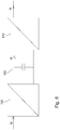
- FIG. 7 shows a variant in which the switch 290 switches a resistor R between two of the phase conductors to achieve an energy extraction, which in turn causes a rotation of the nacelle 110.
- the remarks in connection with the FIG. 4 apply in this variant according to FIG. 7 corresponding.
- the variant according to FIG. 7 can thus also in the embodiments according to the Figures 2 and 3 be used.
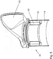
- FIG. 5 shows an embodiment of a possible mechanical structure for the rotary transformer 30 according to FIG. 2 , It can be seen from the rotary transformer 30, the primary three-phase coil system 31 and the secondary three-phase coil system 32nd
- Embodiments may (but do not have to) have one or more of the following characteristics or features, depending on the embodiment: It is possible to use the Drehübertragerkals together with a Mehrsystemumrichter for power transmission of nacelle in the tower and thus to the grid connection point and rotation of the nacelle by appropriate positional angle-dependent current component of the main inverter to generate a tangential torque within the Drehübertragers while using the Drehübertragers as Umrichter-Mittelschreibstrafo.
- the rotary transformer is preferably arranged between gondola and tower head as an assembly with a mechanical tower flange, a mechanical gondola flange, a medium voltage connection on the tower flange, low voltage connections on the gondola flange, preferably with two mechanical bearings (eg ball slewing connectors) to ensure the air gap between the stator and the tower Rotor and a capacitive transmission system for data.
- two mechanical bearings eg ball slewing connectors
- One or more rotary joints may be disposed between the tower head and the gondola shaft such that a tangential air gap moment rotates the gondola in one direction or the other depending on the direction and magnitude of that torque or against external force acting on the wind turbine rotor or nacelle accelerating acts.
- a correspondingly provided superimposed attitude control makes it possible to position the nacelle to the tower or to guide it to the new position.
- the rotary transformer (s) can take over the function of the medium-voltage transformers which connect the converters or converter systems to the mains.
- the rotary transformer may include, in addition to the inductive transmission system (s), one or more capacitive transmission systems capable of transmitting data from the stationary tower to the rotatable nacelle.
- the rotary joints may include, in addition to the secondary three-phase coil system (s), one or more secondary three-phase coil systems which supply additional energy consumers required in the nacelle separately from the main converter system with the necessary voltage (s).
- the generation of the torque can be done by the mains side inverter.
- the necessary torque can also be achieved by closing a switch (see switch 290 in the FIGS. 4 and 7 ) respectively.
- the two short-circuited or resistively loaded phases of the secondary system act like a short-circuit cage of an asynchronous motor. The result is a starting torque that accelerates the nacelle in the direction of the rotating field.
- the switch variant can after FIG. 4 or FIG. 7 be used accordingly for both directions of rotation.
Landscapes
- Engineering & Computer Science (AREA)
- Life Sciences & Earth Sciences (AREA)
- Sustainable Development (AREA)
- Sustainable Energy (AREA)
- Chemical & Material Sciences (AREA)
- Combustion & Propulsion (AREA)
- Mechanical Engineering (AREA)
- General Engineering & Computer Science (AREA)
- Power Engineering (AREA)
- Control Of Eletrric Generators (AREA)
- Wind Motors (AREA)
Claims (9)
- Éolienne (10) destinée à générer de l'énergie électrique, comprenant au moins une hélice (100) fixée tournante à une nacelle (110), un générateur (120) couplé à l'hélice (100) et une tour (115) portant la nacelle (110), dans laquelle la nacelle (110) peut tourner par rapport à la tour (115),
dans laquelle
il est prévu entre la nacelle (110) et la tour (115) un transformateur rotatif électromagnétique (30) qui injecte l'énergie électrique générée par le générateur (120) dans une ligne électrique installée dans la tour (115),
caractérisée en ce que- l'éolienne (10) comporte un dispositif de commande (40) qui est connecté à un onduleur (20) et commande ce dernier,- dans laquelle le dispositif de commande (40) est conçu de manière à ce que, dans le cas où la nacelle (110) doit être amenée à tourner par rapport à la tour (115), il assure la commande de l'onduleur (20) de telle façon que le transformateur rotatif (30) génère un couple mécanique permettant de faire tourner la nacelle (110) par rapport à la tour (115) et que la nacelle (110) soit mise en rotation au moyen dudit couple. - Éolienne (10) selon la revendication 1,
caractérisée en ce que
le transformateur rotatif (30) comprend un système de bobine triphasé primaire (31) et un système de bobine triphasé secondaire (32) séparés mécaniquement l'un de l'autre par un interstice mais couplés magnétiquement l'un à l'autre. - Éolienne (10) selon l'une des revendications précédentes,
caractérisée en ce que le nombre d'enroulements du côté primaire (PS) du transformateur rotatif (30) et celui du côté secondaire (SS) du transformateur rotatif (30) sont sélectionnés de manière à ce que la tension secondaire générée du côté secondaire soit supérieure à la tension primaire injectée sur le côté primaire. - Éolienne (10) selon l'une des revendications précédentes,
caractérisée en ce que- la tension primaire du côté primaire du transformateur rotatif (30) est comprise entre 100 V et 4 kV et- le rapport de transmission du transformateur rotatif (30) est sélectionné de manière à ce que la tension secondaire du côté secondaire soit comprise entre 10 kV et 100 kV. - Éolienne (10) selon l'une des revendications précédentes,
caractérisée en ce que
l'onduleur (20) est disposé électriquement entre le générateur (120) et le transformateur rotatif (30) et injecte le courant dans le côté primaire du transformateur rotatif (30). - Éolienne (10) selon l'une des revendications précédentes,
caractérisée en ce que- la ligne électrique (117) installée dans la tour (115) est connectée à un réseau de transmission d'énergie externe (900) ayant une fréquence de réseau prédéterminée et- l'onduleur (20) injecte dans le transformateur rotatif (30) un courant primaire dont la fréquence et/ou la position de phase s'écarte de la fréquence du réseau ou de la position de phase du réseau, lorsque le transformateur rotatif (30) doit générer un couple permettant de faire tourner la nacelle (110) par rapport à la tour (115), provoquant ainsi notamment un glissement magnétique entre le système de bobine triphasé primaire (31) et le système de bobine triphasé secondaire (32). - Éolienne (10) selon l'une des revendications précédentes,
caractérisé en ce que- l'onduleur (20) comporte au moins deux branches d'onduleur (21, 22) qui génèrent chacune un courant partiel primaire,- le transformateur rotatif (30) comporte au moins deux unités de transformateur rotatif (250, 280) qui comprennent chacune un système de bobine triphasé primaire (230, 260) et un système de bobine triphasé secondaire (240, 270) couplé à ce dernier,- les unités de transformateur rotatif sont respectivement alimentées côté entrée par l'une des branches et sont respectivement reliées côté sortie à la ligne électrique installée dans la tour (115), et- le transformateur rotatif (30) génère un couple permettant de faire tourner la nacelle (110) par rapport à la tour (115) dans le cas où les couples générés par les unités de transformateur rotatif génèrent un couple total différent de zéro. - Éolienne (10) selon la revendication 7, caractérisée en ce que- l'une des unités de transformateur rotatif génère un système de champ magnétique tournant en sens horaire et en ce qu'une autre d'entre elles génère un système de champ magnétique tournant en sens antihoraire, et- le dispositif de commande (40) et l'onduleur (20) définissent le sens de rotation de la nacelle (110) en générant un couple permettant de faire tourner la nacelle (110) au moyen du système de champ magnétique tournant en sens horaire ou du système de champ magnétique tournant en sens antihoraire.
- Procédé pour faire fonctionner une éolienne (10) destinée à générer de l'énergie électrique, dans lequel l'éolienne (10) comprend une hélice (100) fixée tournante à une nacelle (110), un générateur (120) couplé à l'hélice (100) et une tour (115) portant la nacelle (110), dans lequel la nacelle (110) peut tourner par rapport à la tour (115),
dans lequel- il est prévu entre la nacelle (110) et la tour (115) un transformateur rotatif électromagnétique (30) et- l'énergie électrique générée par le générateur (120) est injectée au moyen du transformateur rotatif (30) dans une ligne électrique installée dans la tour (115),caractérisé en ce que
la nacelle (110) est amenée à tourner par rapport à la tour (115) en réglant le courant injecté dans le transformateur rotatif (30) au moyen d'un onduleur (20) qui est disposé électriquement entre le générateur (120) et le transformateur rotatif (30) de telle façon que le transformateur rotatif (30) génère un couple mécanique permettant de faire tourner la nacelle (110) par rapport à la tour (115).
Applications Claiming Priority (1)
| Application Number | Priority Date | Filing Date | Title |
|---|---|---|---|
| DE102016206395.2A DE102016206395A1 (de) | 2016-04-15 | 2016-04-15 | Windenergieanlage |
Publications (2)
| Publication Number | Publication Date |
|---|---|
| EP3232052A1 EP3232052A1 (fr) | 2017-10-18 |
| EP3232052B1 true EP3232052B1 (fr) | 2019-05-22 |
Family
ID=58501283
Family Applications (1)
| Application Number | Title | Priority Date | Filing Date |
|---|---|---|---|
| EP17165229.0A Active EP3232052B1 (fr) | 2016-04-15 | 2017-04-06 | Éolienne |
Country Status (2)
| Country | Link |
|---|---|
| EP (1) | EP3232052B1 (fr) |
| DE (1) | DE102016206395A1 (fr) |
Family Cites Families (4)
| Publication number | Priority date | Publication date | Assignee | Title |
|---|---|---|---|---|
| GB0513821D0 (en) * | 2005-07-06 | 2005-08-10 | Rolls Royce Plc | Transformer |
| GB0819561D0 (en) * | 2008-10-27 | 2008-12-03 | Rolls Royce Plc | A distributed electrical generation system |
| DE102010040366A1 (de) * | 2010-09-07 | 2012-03-08 | rc-direct Unternehmergesellschaft (haftungsbeschränkt) | Leistungsübertrager für ein Windrad |
| CA2816166A1 (fr) * | 2010-10-29 | 2012-05-03 | 3E | Systeme destine a un transfert de puissance sans contact entre la nacelle et la tour d'une eolienne |
-
2016
- 2016-04-15 DE DE102016206395.2A patent/DE102016206395A1/de not_active Withdrawn
-
2017
- 2017-04-06 EP EP17165229.0A patent/EP3232052B1/fr active Active
Non-Patent Citations (1)
| Title |
|---|
| None * |
Also Published As
| Publication number | Publication date |
|---|---|
| DE102016206395A1 (de) | 2017-10-19 |
| EP3232052A1 (fr) | 2017-10-18 |
Similar Documents
| Publication | Publication Date | Title |
|---|---|---|
| EP2984725B1 (fr) | Éolienne à plage de tension étendue | |
| EP2713477B1 (fr) | Procédé de fonctionnement d'un circuit électrique pour parc éolien | |
| EP2696464B1 (fr) | Centrale photovoltaïque | |
| EP3724969B1 (fr) | Combinaison d'une machine électrique triphasée avec une unité convertisseur et éolienne | |
| EP1959136B1 (fr) | Parc éolien comprenant des éoliennes dotées d'un angle de pivotement décalé l'un par rapport à l'autre | |
| WO2015090936A1 (fr) | Centrale électrique | |
| EP1513251B1 (fr) | Procédé et dispositif d'exploitation d'une machine à courant alternatif à double alimentation en tant que génératrice dans une éolienne | |
| DE2205076C3 (de) | Mehrphasige Hochspannungsleitung | |
| EP3232052B1 (fr) | Éolienne | |
| EP2117108B1 (fr) | Procédé de démarrage d'un système destiné à la production d'énergie électrique | |
| DE102010062060A1 (de) | Drehstrom-Asynchronmaschine und Verfahren zum Betreiben einer Drehstrom-Asynchronmaschine in einem Luft- oder Raumfahrzeug | |
| EP2795771B1 (fr) | Générateur d'une éolienne à entraînement direct | |
| EP2771663B1 (fr) | Dispositif de contrôle et procédé de contrôle d'une première et/ou d'une seconde machine électrique | |
| EP2388904A1 (fr) | Oonduleur triphasée et procédé de fonctionnement d'un onduleur triphasée | |
| EP3393028B1 (fr) | Éolienne pourvue de système convertisseur permettant de réduire le rayonnement em | |
| DE102012201762A1 (de) | Windkraftgenerator und Blattmontageverfahren | |
| EP2117110B1 (fr) | Système pour générer de l'énergie électrique | |
| DE102015201477B4 (de) | Aggregat zur Stromerzeugung, Stromnetz mit einem solchen Aggregat, Kraftfahrzeug mit einem solchen Stromnetz oder Aggregat, und Verfahren zum Betreiben eines solchen Aggregats zur Stromerzeugung | |
| EP1426616B1 (fr) | Connexion d'éolienne à un réseau électrique | |
| EP2521240A2 (fr) | Commutation électrique pour un parc éolien | |
| EP3900141B1 (fr) | Procédé et dispositif pour un réseau à courant alternatif à débit de puissance accru | |
| EP3349350A1 (fr) | Procédé de fonctionnement d'une machine asynchrone en mode générateur | |
| EP3280911B1 (fr) | Dispositif de réglage pour régler une pale de rotor d'éolienne | |
| DE102015213048A1 (de) | Anordnung zum Bereitstellen eines Ausgangspotentials und Fahrzeug mit einer solchen Anordnung | |
| AT136326B (de) | Induktionsreglerschaltung zur Regelung der Spannung und Phasenverschiebung bei beliebiger Phasenzahl. |
Legal Events
| Date | Code | Title | Description |
|---|---|---|---|
| PUAI | Public reference made under article 153(3) epc to a published international application that has entered the european phase |
Free format text: ORIGINAL CODE: 0009012 |
|
| STAA | Information on the status of an ep patent application or granted ep patent |
Free format text: STATUS: THE APPLICATION HAS BEEN PUBLISHED |
|
| AK | Designated contracting states |
Kind code of ref document: A1 Designated state(s): AL AT BE BG CH CY CZ DE DK EE ES FI FR GB GR HR HU IE IS IT LI LT LU LV MC MK MT NL NO PL PT RO RS SE SI SK SM TR |
|
| AX | Request for extension of the european patent |
Extension state: BA ME |
|
| STAA | Information on the status of an ep patent application or granted ep patent |
Free format text: STATUS: REQUEST FOR EXAMINATION WAS MADE |
|
| 17P | Request for examination filed |
Effective date: 20171117 |
|
| RBV | Designated contracting states (corrected) |
Designated state(s): AL AT BE BG CH CY CZ DE DK EE ES FI FR GB GR HR HU IE IS IT LI LT LU LV MC MK MT NL NO PL PT RO RS SE SI SK SM TR |
|
| GRAP | Despatch of communication of intention to grant a patent |
Free format text: ORIGINAL CODE: EPIDOSNIGR1 |
|
| STAA | Information on the status of an ep patent application or granted ep patent |
Free format text: STATUS: GRANT OF PATENT IS INTENDED |
|
| INTG | Intention to grant announced |
Effective date: 20181120 |
|
| GRAS | Grant fee paid |
Free format text: ORIGINAL CODE: EPIDOSNIGR3 |
|
| GRAA | (expected) grant |
Free format text: ORIGINAL CODE: 0009210 |
|
| STAA | Information on the status of an ep patent application or granted ep patent |
Free format text: STATUS: THE PATENT HAS BEEN GRANTED |
|
| AK | Designated contracting states |
Kind code of ref document: B1 Designated state(s): AL AT BE BG CH CY CZ DE DK EE ES FI FR GB GR HR HU IE IS IT LI LT LU LV MC MK MT NL NO PL PT RO RS SE SI SK SM TR |
|
| REG | Reference to a national code |
Ref country code: GB Ref legal event code: FG4D Free format text: NOT ENGLISH |
|
| REG | Reference to a national code |
Ref country code: CH Ref legal event code: EP |
|
| REG | Reference to a national code |
Ref country code: IE Ref legal event code: FG4D Free format text: LANGUAGE OF EP DOCUMENT: GERMAN |
|
| REG | Reference to a national code |
Ref country code: DE Ref legal event code: R096 Ref document number: 502017001373 Country of ref document: DE |
|
| REG | Reference to a national code |
Ref country code: AT Ref legal event code: REF Ref document number: 1136431 Country of ref document: AT Kind code of ref document: T Effective date: 20190615 |
|
| REG | Reference to a national code |
Ref country code: NL Ref legal event code: MP Effective date: 20190522 |
|
| REG | Reference to a national code |
Ref country code: LT Ref legal event code: MG4D |
|
| PG25 | Lapsed in a contracting state [announced via postgrant information from national office to epo] |
Ref country code: FI Free format text: LAPSE BECAUSE OF FAILURE TO SUBMIT A TRANSLATION OF THE DESCRIPTION OR TO PAY THE FEE WITHIN THE PRESCRIBED TIME-LIMIT Effective date: 20190522 Ref country code: NO Free format text: LAPSE BECAUSE OF FAILURE TO SUBMIT A TRANSLATION OF THE DESCRIPTION OR TO PAY THE FEE WITHIN THE PRESCRIBED TIME-LIMIT Effective date: 20190822 Ref country code: ES Free format text: LAPSE BECAUSE OF FAILURE TO SUBMIT A TRANSLATION OF THE DESCRIPTION OR TO PAY THE FEE WITHIN THE PRESCRIBED TIME-LIMIT Effective date: 20190522 Ref country code: PT Free format text: LAPSE BECAUSE OF FAILURE TO SUBMIT A TRANSLATION OF THE DESCRIPTION OR TO PAY THE FEE WITHIN THE PRESCRIBED TIME-LIMIT Effective date: 20190922 Ref country code: AL Free format text: LAPSE BECAUSE OF FAILURE TO SUBMIT A TRANSLATION OF THE DESCRIPTION OR TO PAY THE FEE WITHIN THE PRESCRIBED TIME-LIMIT Effective date: 20190522 Ref country code: SE Free format text: LAPSE BECAUSE OF FAILURE TO SUBMIT A TRANSLATION OF THE DESCRIPTION OR TO PAY THE FEE WITHIN THE PRESCRIBED TIME-LIMIT Effective date: 20190522 Ref country code: HR Free format text: LAPSE BECAUSE OF FAILURE TO SUBMIT A TRANSLATION OF THE DESCRIPTION OR TO PAY THE FEE WITHIN THE PRESCRIBED TIME-LIMIT Effective date: 20190522 Ref country code: NL Free format text: LAPSE BECAUSE OF FAILURE TO SUBMIT A TRANSLATION OF THE DESCRIPTION OR TO PAY THE FEE WITHIN THE PRESCRIBED TIME-LIMIT Effective date: 20190522 Ref country code: LT Free format text: LAPSE BECAUSE OF FAILURE TO SUBMIT A TRANSLATION OF THE DESCRIPTION OR TO PAY THE FEE WITHIN THE PRESCRIBED TIME-LIMIT Effective date: 20190522 |
|
| PG25 | Lapsed in a contracting state [announced via postgrant information from national office to epo] |
Ref country code: BG Free format text: LAPSE BECAUSE OF FAILURE TO SUBMIT A TRANSLATION OF THE DESCRIPTION OR TO PAY THE FEE WITHIN THE PRESCRIBED TIME-LIMIT Effective date: 20190822 Ref country code: RS Free format text: LAPSE BECAUSE OF FAILURE TO SUBMIT A TRANSLATION OF THE DESCRIPTION OR TO PAY THE FEE WITHIN THE PRESCRIBED TIME-LIMIT Effective date: 20190522 Ref country code: GR Free format text: LAPSE BECAUSE OF FAILURE TO SUBMIT A TRANSLATION OF THE DESCRIPTION OR TO PAY THE FEE WITHIN THE PRESCRIBED TIME-LIMIT Effective date: 20190823 Ref country code: LV Free format text: LAPSE BECAUSE OF FAILURE TO SUBMIT A TRANSLATION OF THE DESCRIPTION OR TO PAY THE FEE WITHIN THE PRESCRIBED TIME-LIMIT Effective date: 20190522 |
|
| PG25 | Lapsed in a contracting state [announced via postgrant information from national office to epo] |
Ref country code: SK Free format text: LAPSE BECAUSE OF FAILURE TO SUBMIT A TRANSLATION OF THE DESCRIPTION OR TO PAY THE FEE WITHIN THE PRESCRIBED TIME-LIMIT Effective date: 20190522 Ref country code: RO Free format text: LAPSE BECAUSE OF FAILURE TO SUBMIT A TRANSLATION OF THE DESCRIPTION OR TO PAY THE FEE WITHIN THE PRESCRIBED TIME-LIMIT Effective date: 20190522 Ref country code: CZ Free format text: LAPSE BECAUSE OF FAILURE TO SUBMIT A TRANSLATION OF THE DESCRIPTION OR TO PAY THE FEE WITHIN THE PRESCRIBED TIME-LIMIT Effective date: 20190522 Ref country code: EE Free format text: LAPSE BECAUSE OF FAILURE TO SUBMIT A TRANSLATION OF THE DESCRIPTION OR TO PAY THE FEE WITHIN THE PRESCRIBED TIME-LIMIT Effective date: 20190522 Ref country code: DK Free format text: LAPSE BECAUSE OF FAILURE TO SUBMIT A TRANSLATION OF THE DESCRIPTION OR TO PAY THE FEE WITHIN THE PRESCRIBED TIME-LIMIT Effective date: 20190522 |
|
| REG | Reference to a national code |
Ref country code: DE Ref legal event code: R097 Ref document number: 502017001373 Country of ref document: DE |
|
| PG25 | Lapsed in a contracting state [announced via postgrant information from national office to epo] |
Ref country code: IT Free format text: LAPSE BECAUSE OF FAILURE TO SUBMIT A TRANSLATION OF THE DESCRIPTION OR TO PAY THE FEE WITHIN THE PRESCRIBED TIME-LIMIT Effective date: 20190522 Ref country code: SM Free format text: LAPSE BECAUSE OF FAILURE TO SUBMIT A TRANSLATION OF THE DESCRIPTION OR TO PAY THE FEE WITHIN THE PRESCRIBED TIME-LIMIT Effective date: 20190522 |
|
| PLBE | No opposition filed within time limit |
Free format text: ORIGINAL CODE: 0009261 |
|
| STAA | Information on the status of an ep patent application or granted ep patent |
Free format text: STATUS: NO OPPOSITION FILED WITHIN TIME LIMIT |
|
| PG25 | Lapsed in a contracting state [announced via postgrant information from national office to epo] |
Ref country code: TR Free format text: LAPSE BECAUSE OF FAILURE TO SUBMIT A TRANSLATION OF THE DESCRIPTION OR TO PAY THE FEE WITHIN THE PRESCRIBED TIME-LIMIT Effective date: 20190522 |
|
| 26N | No opposition filed |
Effective date: 20200225 |
|
| PG25 | Lapsed in a contracting state [announced via postgrant information from national office to epo] |
Ref country code: PL Free format text: LAPSE BECAUSE OF FAILURE TO SUBMIT A TRANSLATION OF THE DESCRIPTION OR TO PAY THE FEE WITHIN THE PRESCRIBED TIME-LIMIT Effective date: 20190522 |
|
| PG25 | Lapsed in a contracting state [announced via postgrant information from national office to epo] |
Ref country code: SI Free format text: LAPSE BECAUSE OF FAILURE TO SUBMIT A TRANSLATION OF THE DESCRIPTION OR TO PAY THE FEE WITHIN THE PRESCRIBED TIME-LIMIT Effective date: 20190522 |
|
| PG25 | Lapsed in a contracting state [announced via postgrant information from national office to epo] |
Ref country code: MC Free format text: LAPSE BECAUSE OF FAILURE TO SUBMIT A TRANSLATION OF THE DESCRIPTION OR TO PAY THE FEE WITHIN THE PRESCRIBED TIME-LIMIT Effective date: 20190522 |
|
| REG | Reference to a national code |
Ref country code: CH Ref legal event code: PL |
|
| PG25 | Lapsed in a contracting state [announced via postgrant information from national office to epo] |
Ref country code: FR Free format text: LAPSE BECAUSE OF NON-PAYMENT OF DUE FEES Effective date: 20200430 Ref country code: LI Free format text: LAPSE BECAUSE OF NON-PAYMENT OF DUE FEES Effective date: 20200430 Ref country code: LU Free format text: LAPSE BECAUSE OF NON-PAYMENT OF DUE FEES Effective date: 20200406 Ref country code: CH Free format text: LAPSE BECAUSE OF NON-PAYMENT OF DUE FEES Effective date: 20200430 |
|
| REG | Reference to a national code |
Ref country code: BE Ref legal event code: MM Effective date: 20200430 |
|
| PG25 | Lapsed in a contracting state [announced via postgrant information from national office to epo] |
Ref country code: BE Free format text: LAPSE BECAUSE OF NON-PAYMENT OF DUE FEES Effective date: 20200430 |
|
| PG25 | Lapsed in a contracting state [announced via postgrant information from national office to epo] |
Ref country code: IE Free format text: LAPSE BECAUSE OF NON-PAYMENT OF DUE FEES Effective date: 20200406 |
|
| GBPC | Gb: european patent ceased through non-payment of renewal fee |
Effective date: 20210406 |
|
| PG25 | Lapsed in a contracting state [announced via postgrant information from national office to epo] |
Ref country code: GB Free format text: LAPSE BECAUSE OF NON-PAYMENT OF DUE FEES Effective date: 20210406 |
|
| PG25 | Lapsed in a contracting state [announced via postgrant information from national office to epo] |
Ref country code: MT Free format text: LAPSE BECAUSE OF FAILURE TO SUBMIT A TRANSLATION OF THE DESCRIPTION OR TO PAY THE FEE WITHIN THE PRESCRIBED TIME-LIMIT Effective date: 20190522 Ref country code: CY Free format text: LAPSE BECAUSE OF FAILURE TO SUBMIT A TRANSLATION OF THE DESCRIPTION OR TO PAY THE FEE WITHIN THE PRESCRIBED TIME-LIMIT Effective date: 20190522 |
|
| PG25 | Lapsed in a contracting state [announced via postgrant information from national office to epo] |
Ref country code: MK Free format text: LAPSE BECAUSE OF FAILURE TO SUBMIT A TRANSLATION OF THE DESCRIPTION OR TO PAY THE FEE WITHIN THE PRESCRIBED TIME-LIMIT Effective date: 20190522 Ref country code: IS Free format text: LAPSE BECAUSE OF FAILURE TO SUBMIT A TRANSLATION OF THE DESCRIPTION OR TO PAY THE FEE WITHIN THE PRESCRIBED TIME-LIMIT Effective date: 20190922 |
|
| PGFP | Annual fee paid to national office [announced via postgrant information from national office to epo] |
Ref country code: DE Payment date: 20220430 Year of fee payment: 6 |
|
| REG | Reference to a national code |
Ref country code: AT Ref legal event code: MM01 Ref document number: 1136431 Country of ref document: AT Kind code of ref document: T Effective date: 20220406 |
|
| PG25 | Lapsed in a contracting state [announced via postgrant information from national office to epo] |
Ref country code: AT Free format text: LAPSE BECAUSE OF NON-PAYMENT OF DUE FEES Effective date: 20220406 |
|
| REG | Reference to a national code |
Ref country code: DE Ref legal event code: R119 Ref document number: 502017001373 Country of ref document: DE |
|
| PG25 | Lapsed in a contracting state [announced via postgrant information from national office to epo] |
Ref country code: DE Free format text: LAPSE BECAUSE OF NON-PAYMENT OF DUE FEES Effective date: 20231103 |