EP3232052B1 - Wind energy system - Google Patents
Wind energy system Download PDFInfo
- Publication number
- EP3232052B1 EP3232052B1 EP17165229.0A EP17165229A EP3232052B1 EP 3232052 B1 EP3232052 B1 EP 3232052B1 EP 17165229 A EP17165229 A EP 17165229A EP 3232052 B1 EP3232052 B1 EP 3232052B1
- Authority
- EP
- European Patent Office
- Prior art keywords
- rotary transformer
- nacelle
- tower
- primary
- converter
- Prior art date
- Legal status (The legal status is an assumption and is not a legal conclusion. Google has not performed a legal analysis and makes no representation as to the accuracy of the status listed.)
- Active
Links
- 230000005540 biological transmission Effects 0.000 claims description 28
- 238000000034 method Methods 0.000 claims description 4
- 238000004804 winding Methods 0.000 claims description 2
- 238000009434 installation Methods 0.000 claims 11
- 230000009466 transformation Effects 0.000 claims 1
- 238000004891 communication Methods 0.000 description 3
- 239000004020 conductor Substances 0.000 description 3
- 230000005611 electricity Effects 0.000 description 3
- 208000012886 Vertigo Diseases 0.000 description 2
- 230000015572 biosynthetic process Effects 0.000 description 2
- 238000000605 extraction Methods 0.000 description 2
- 238000006243 chemical reaction Methods 0.000 description 1
- 230000001419 dependent effect Effects 0.000 description 1
- 230000009977 dual effect Effects 0.000 description 1
- 230000006698 induction Effects 0.000 description 1
- 230000001939 inductive effect Effects 0.000 description 1
Images


Classifications
-
- F—MECHANICAL ENGINEERING; LIGHTING; HEATING; WEAPONS; BLASTING
- F03—MACHINES OR ENGINES FOR LIQUIDS; WIND, SPRING, OR WEIGHT MOTORS; PRODUCING MECHANICAL POWER OR A REACTIVE PROPULSIVE THRUST, NOT OTHERWISE PROVIDED FOR
- F03D—WIND MOTORS
- F03D9/00—Adaptations of wind motors for special use; Combinations of wind motors with apparatus driven thereby; Wind motors specially adapted for installation in particular locations
- F03D9/20—Wind motors characterised by the driven apparatus
- F03D9/25—Wind motors characterised by the driven apparatus the apparatus being an electrical generator
- F03D9/255—Wind motors characterised by the driven apparatus the apparatus being an electrical generator connected to electrical distribution networks; Arrangements therefor
-
- F—MECHANICAL ENGINEERING; LIGHTING; HEATING; WEAPONS; BLASTING
- F03—MACHINES OR ENGINES FOR LIQUIDS; WIND, SPRING, OR WEIGHT MOTORS; PRODUCING MECHANICAL POWER OR A REACTIVE PROPULSIVE THRUST, NOT OTHERWISE PROVIDED FOR
- F03D—WIND MOTORS
- F03D7/00—Controlling wind motors
- F03D7/02—Controlling wind motors the wind motors having rotation axis substantially parallel to the air flow entering the rotor
- F03D7/0204—Controlling wind motors the wind motors having rotation axis substantially parallel to the air flow entering the rotor for orientation in relation to wind direction
-
- F—MECHANICAL ENGINEERING; LIGHTING; HEATING; WEAPONS; BLASTING
- F03—MACHINES OR ENGINES FOR LIQUIDS; WIND, SPRING, OR WEIGHT MOTORS; PRODUCING MECHANICAL POWER OR A REACTIVE PROPULSIVE THRUST, NOT OTHERWISE PROVIDED FOR
- F03D—WIND MOTORS
- F03D80/00—Details, components or accessories not provided for in groups F03D1/00 - F03D17/00
- F03D80/80—Arrangement of components within nacelles or towers
- F03D80/82—Arrangement of components within nacelles or towers of electrical components
- F03D80/85—Cabling
-
- H—ELECTRICITY
- H01—ELECTRIC ELEMENTS
- H01F—MAGNETS; INDUCTANCES; TRANSFORMERS; SELECTION OF MATERIALS FOR THEIR MAGNETIC PROPERTIES
- H01F38/00—Adaptations of transformers or inductances for specific applications or functions
- H01F38/18—Rotary transformers
-
- F—MECHANICAL ENGINEERING; LIGHTING; HEATING; WEAPONS; BLASTING
- F05—INDEXING SCHEMES RELATING TO ENGINES OR PUMPS IN VARIOUS SUBCLASSES OF CLASSES F01-F04
- F05B—INDEXING SCHEME RELATING TO WIND, SPRING, WEIGHT, INERTIA OR LIKE MOTORS, TO MACHINES OR ENGINES FOR LIQUIDS COVERED BY SUBCLASSES F03B, F03D AND F03G
- F05B2240/00—Components
- F05B2240/90—Mounting on supporting structures or systems
- F05B2240/91—Mounting on supporting structures or systems on a stationary structure
- F05B2240/912—Mounting on supporting structures or systems on a stationary structure on a tower
-
- F—MECHANICAL ENGINEERING; LIGHTING; HEATING; WEAPONS; BLASTING
- F05—INDEXING SCHEMES RELATING TO ENGINES OR PUMPS IN VARIOUS SUBCLASSES OF CLASSES F01-F04
- F05B—INDEXING SCHEME RELATING TO WIND, SPRING, WEIGHT, INERTIA OR LIKE MOTORS, TO MACHINES OR ENGINES FOR LIQUIDS COVERED BY SUBCLASSES F03B, F03D AND F03G
- F05B2270/00—Control
- F05B2270/30—Control parameters, e.g. input parameters
- F05B2270/329—Azimuth or yaw angle
-
- Y—GENERAL TAGGING OF NEW TECHNOLOGICAL DEVELOPMENTS; GENERAL TAGGING OF CROSS-SECTIONAL TECHNOLOGIES SPANNING OVER SEVERAL SECTIONS OF THE IPC; TECHNICAL SUBJECTS COVERED BY FORMER USPC CROSS-REFERENCE ART COLLECTIONS [XRACs] AND DIGESTS
- Y02—TECHNOLOGIES OR APPLICATIONS FOR MITIGATION OR ADAPTATION AGAINST CLIMATE CHANGE
- Y02E—REDUCTION OF GREENHOUSE GAS [GHG] EMISSIONS, RELATED TO ENERGY GENERATION, TRANSMISSION OR DISTRIBUTION
- Y02E10/00—Energy generation through renewable energy sources
- Y02E10/70—Wind energy
- Y02E10/72—Wind turbines with rotation axis in wind direction
-
- Y—GENERAL TAGGING OF NEW TECHNOLOGICAL DEVELOPMENTS; GENERAL TAGGING OF CROSS-SECTIONAL TECHNOLOGIES SPANNING OVER SEVERAL SECTIONS OF THE IPC; TECHNICAL SUBJECTS COVERED BY FORMER USPC CROSS-REFERENCE ART COLLECTIONS [XRACs] AND DIGESTS
- Y02—TECHNOLOGIES OR APPLICATIONS FOR MITIGATION OR ADAPTATION AGAINST CLIMATE CHANGE
- Y02E—REDUCTION OF GREENHOUSE GAS [GHG] EMISSIONS, RELATED TO ENERGY GENERATION, TRANSMISSION OR DISTRIBUTION
- Y02E10/00—Energy generation through renewable energy sources
- Y02E10/70—Wind energy
- Y02E10/728—Onshore wind turbines
Definitions
- the invention relates to wind turbines for generating electrical energy with at least one rotatably mounted on a nacelle propeller, coupled to the propeller generator and a nacelle-bearing tower, wherein the nacelle is rotatable relative to the tower.
- the nacelle In conventional wind turbines, the nacelle is rotated relative to the tower by means of direct drives, hybrid drives or multi-stage transmissions.
- the transmission of energy between the nacelle and the tower usually takes place by means of cables.
- Wind turbines are also known in which an electromagnetic rotary transformer is arranged between the nacelle and the tower, which can transmit the electrical energy generated by the generator to the tower.
- the invention has for its object to improve a wind turbine of the type described above in terms of the interface between the nacelle and tower.
- a significant advantage of the wind power plant according to the invention is the fact that in this an electromagnetic rotary transformer is arranged.
- Such a rotary transformer On the one hand, it allows you to turn the nacelle around the tower without having to turn it back, unlike conventional wind turbines with a cable interface between the nacelle and the tower.
- the rotary transformer can be used to adapt the voltage level on the output side of the generator to the voltage level of an energy transmission network to be fed with energy.
- the rotary transformer it is possible by means of the rotary transformer to transform the low voltage usually generated by the generator or usually only small mean voltage (generally up to a maximum of 4 kV) to a higher medium voltage level, for example to a medium voltage level of 20 kV.
- a step-up it is possible to use in the tower area, so from the base of the wind turbine to the interface between the nacelle and the top of a relatively thin cross-section energy transmission line.
- a torque can be generated by a suitable electrical control of the rotary transformer between the primary side and the secondary side by the rotary transformer, through which the nacelle can be pivoted relative to the tower.
- the rotary transformer can perform a dual function: firstly, it can make an up-conversion or a voltage level change between the output voltage of the generator and the energy transmission network to be fed, and secondly, it can provide a torque for pivoting the nacelle, if so is desired.
- a separate nacelle drive is thus not necessary in the wind turbine according to the invention.
- the rotary transformer is preferably an electrical transformer in which the primary side can be rotated relative to the secondary side.
- the rotary transformer preferably comprises at least one primary three-phase current coil system and at least one secondary three-phase current coil system, which are mechanically separated from each other in pairs via a gap, but are magnetically coupled to one another.
- the rotary transformer On the primary side of the rotary transformer preferably form electrical coil packages in the form of coil ring segments at least one annular primary three-phase current coil system which faces at least one annular secondary air-current coil system on the secondary side to form at least one annular air gap.
- the annular secondary three-phase current coil system is preferably also formed by electrical coil packages in the form of coil ring segments; these are opposite those of the primary three-phase coil system.
- the three-phase coil systems are preferably three-phase or at least three-phase.
- the number of windings on the primary side of the rotary transformer and that on the secondary side of the rotary transformer are preferably chosen such that the secondary voltage generated on the secondary side is greater than the primary voltage fed in on the primary side.
- the primary voltage on the primary side of the rotary transformer is preferably in the range between 100 V and 4 kV.
- the transmission ratio of the rotary transformer is preferably selected such that the secondary voltage on the secondary side is in the range between 10 and 100 kV.
- the converter is preferably configured such that it can set the current fed into the primary side of the rotary transformer such that the rotary transformer generates a mechanical torque for rotating the nacelle relative to the rotor Can generate tower.
- the corresponding adjustment of the current can be effected, for example, by selecting the amplitude, frequency and / or phase position of the feed current fed into the rotary transformer relative to the amplitude, frequency and / or phase position of the energy transmission network to be fed.
- control device to drive the inverter such that this in the primary side of the rotation transformer supplied power sets such that the rotary transformer generates a mechanical torque for rotating the nacelle relative to the tower.
- the corresponding adjustment of the current the control device, for example, by selecting the amplitude, frequency and / or phase of the current injected into the rotary transformer current relative to the amplitude, frequency and / or phase position of the energy transmission network to be fed.
- control device can take energy (for example by means of a switch or a switched resistor) from an intermediate circuit of the converter or from an intermediate circuit of a converter branch of the converter in order to generate a torque.
- energy for example by means of a switch or a switched resistor
- an additional asynchronous torque-forming rotating field component is formed in the air gap of the rotary transformer according to the operation of an Asynchronklafigtechnikrs or an Asynchroschleifringierirs that generates a torque that accelerates the nacelle.
- control device - in one area between the converter output and the primary side of the rotary transformer - short circuit or resistance load by means of one or more electrical switch phases of a three- or multi-phase primary-side connection line, which feeds the rotary transformer primary side according to the mode of action of an Asynchronklafigtechnikrs or an asynchronous slip ring rotor to cause a rotation.
- the inverter feeds an additional primary current, preferably superimposed on the main supply current, into the rotary transformer whose frequency deviates from the mains frequency when the rotary transformer is to generate a torque for rotating the nacelle relative to the tower; this leads to a magnetic slip between the primary three-phase coil system and the secondary three-phase current coil system and thus analogous to an asynchronous machine to a torque.
- the converter has at least two converter branches which each generate a primary partial current
- the rotary transformer has at least two rotary transformer units, each comprising a primary three-phase coil system and a coupled with this secondary three-phase coil system
- the rotary transmitter units on the input side of each of the Umrichtzweige be energized and the output side in each case with the laid in the tower electrical line in communication
- the rotary transformer causes a torque for rotation of the nacelle relative to the tower, if generated by the rotary transmitter units generate a non-zero sum torque.
- one of the rotary transmitter units generates a clockwise rotating field system and another a left-handed rotating field system.
- the control device and the converter preferably determine the direction of rotation of the nacelle by selectively supplying or "favoring" the clockwise rotating field system and the left-handed rotating field system with energy to varying degrees.
- the invention further relates to a method of operating a wind turbine for generating electrical power, the wind turbine comprising a propeller rotatably mounted on a nacelle, a generator coupled to the propeller and a tower supporting the nacelle, the nacelle being rotatable relative to the tower is.
- an electromagnetic rotary transformer is arranged between the nacelle and the tower and the electrical energy generated by the generator is fed by means of the rotary transformer into an electrical line laid in the tower.
- the nacelle is rotated relative to the tower by using an electrically connected between the generator and the rotary transformer inverter fed into the primary side of the rotary transformer current - for example by selection of amplitude, frequency or phase - is set such that the Rotary transformer generates a mechanical torque for rotating the nacelle relative to the tower.
- rotary transmitters with two or more rotary transmitter units that, for one or more selected rotary transmitter units, less supply energy is provided on the primary side to generate a torque for rotating the nacelle than at least one other rotary transmitter unit.
- This can be done in an advantageous manner by energy extraction in associated inverter branches or by energy removal between the inverter branches and the respective rotary transmitter unit.
- FIG. 1 shows a schematic side view of an embodiment of a wind turbine 10, which is suitable for generating electrical energy.
- the wind turbine 10 has a nacelle 110, on which a propeller 100 is rotatably mounted.
- Propeller 100 is rotatable about an axis perpendicular to the image plane in FIG. 1 stands.
- the nacelle 110 is supported by a tower 115 in such a way that the nacelle 110 around the in the FIG. 1 is rotatable with the reference numeral Z vertical.
- the turning around the vertical Z is in the FIG. 1 marked with a double arrow with the reference symbol ⁇ .
- FIG. 1 In addition, it can be seen that between the rotatable nacelle 110 and the fixed tower 115, an electromagnetic rotary transformer 30 is provided, which is the one arranged in the rotatable nacelle 110 generator 120 can generate electrical energy generated in a laid in the tower 115 electrical line 117.
- the electric wire 117 is in communication with an external power transmission network that operates in the FIG. 1 only schematically shown and designated there by the reference numeral 900.
- the generator 120 which is mechanically driven by the propeller 100, has its output side connected to a converter 20, which couples the generator 120 and the rotary transformer 30 with one another.
- the rotary transformer 30 has a primary side, which in the FIG. 1 is designated by the reference PS, and a secondary side, in the FIG. 1 the reference SS carries.
- the rotary transformer 30 is preferably an electrical transformer in which the primary side can be rotated relative to the secondary side.
- electrical coil packages in the form of coil ring segments preferably at least one annular primary three-phase current coil system which faces at least one annular secondary three-phase current coil system to form at least one annular air gap.
- the annular secondary three-phase coil system is also formed by electrical coil packages in the form of coil ring segments; these are opposite those of the primary three-phase coil system.
- the three-phase coil systems are preferably three-phase or at least three-phase.
- FIG. 2 shows those related to the FIG. 1 explained components such as the propeller 100 and the generator 120 generating a generator current Ig according to FIG. 1 in another illustration and - in more detail - also an embodiment of a rotary transformer 30, which in the wind turbine 10 according to FIG. 1 can be used.
- the rotary transformer 30 has a primary three-phase coil system 31 on its primary side PS and a secondary three-phase coil system 32 on its secondary side SS.
- the two three-phase coil systems 31 and 32 are mechanically separated, but magnetically coupled together.
- the three-phase coil systems 31 and 32 are preferably three-phase or at least three-phase.
- the electrical lines 117 and 118 are preferably three-phase or at least three-phase lines.
- the primary three-phase coil system 31 and the secondary three-phase coil system 32 are coordinated such that the transmission ratio is greater than 1 and thus the secondary voltage generated on the secondary side SS is greater than the primary voltage fed on the primary side.
- a behavior can be achieved by suitable Wicklungsieresammlung on the primary side PS and the secondary side SS.
- the rotary transformer 30 is designed such that the primary side PS can be operated with a primary voltage between 100 V and 4 kV.
- the transmission ratio of the rotary transformer 30 is preferably selected such that the secondary voltage on the secondary side in the range of an average voltage, preferably between 10 and 100 kV. Particularly preferably, the average voltage is 20 kV, since such a voltage is common in power supply networks.
- the latter works as an electrical transformer which increases the electrical voltage generated by the generator 120, which is usually a low or medium voltage, to a higher level, such as a medium voltage of 20 kV, up-transformed.
- the rotary transformer serves to rotate the rotatable nacelle 110 along the arrow direction ⁇ in FIG. 1 to enable.
- the inverter 20 can be used, which is controlled by a control device 40.
- the control device 40 will drive the converter 20 in such a way that the current Ie fed into the rotary transformer 30 via the line 118 will be the frequency of the external e-energy transmission network 900 (see FIG. 1 ), so that the output from the rotary transformer 30 output side output current Ia has the appropriate network frequency.
- the rotary transformer 30 will exert no or at least no appreciable torque on the rotatable nacelle 110.
- the control device 40 can control the converter 20 in such a way that the rectified current Ie no longer corresponds to the frequency of the external energy transmission network 900 from its frequency or phase position.
- the rotary transformer 30 due to the slip (as in an induction machine) between the magnetic fields of the primary three-phase coil system 31 and the secondary three-phase coil system 32 generate a torque that leads to a pivoting of the pod 110 relative to the tower 115.
- the function of the rotary transformer 30 according to FIG. 2 not only to cause a change in the voltage level on the secondary side SS of the rotary transformer 30 compared to the primary side PS, but also in a pivoting of the rotatable nacelle 110 - for example, by a corresponding control of the inverter 20 - to allow.
- the rotary transformer 30 thus has at least two functions, namely on the one hand an electrical transfer function and on the other hand a mechanical adjustment function by generating a torque.
- a torque generation can also be caused by the fact that in the reversed current Ie two of the phase conductors are short-circuited;
- the torque formation is graphically based on the continued undisturbed rotation of the magnetic field on the secondary side SS of the rotary transformer 30 and the formation of a stationary field on the primary side.
- FIG. 6 shows an embodiment of a possible internal structure of the inverter 20 according to FIG. 2 ,
- the inverter 20 comprises a generator-side converter unit 130 in the form of a rectifier, a DC electrical intermediate circuit 160 and a mains-side converter unit 170 in the form of an inverter.
- FIG. 3 shows a further embodiment of an inverter 20 and a rotary transformer 30, which in the wind turbine 10 according to FIG. 1 can be used.
- the FIG. 3 shows again in detail the propeller 100, the rotatable nacelle 110 and the tower 115th
- the converter 20 has two converter branches 21 and 22, which each comprise a generator-side converter unit 130, an electrical DC voltage intermediate circuit 160 and a mains-side converter unit 170.
- the two Umrichterzweige 21 and 22 respectively generate converted currents Ie1 and Ie2, which are fed via associated multi-phase, preferably three-phase, connecting lines 180 and 181 in the rotary transformer 30.
- the rotary transformer 30 has in the embodiment according to FIG. 3 two rotary transmission units, namely a first rotary transmitter unit, which is designated by the reference numeral 250, and a second rotary transmitter unit, which is designated by the reference numeral 280.
- the first rotary transformer unit 250 includes a first primary three-phase coil system 230 and a first secondary three-phase coil system 240.
- the second rotary transmitter unit 280 includes a second primary three-phase coil system 260 and a second secondary three-phase coil system 270.
- the two rotary transmission units 250 and 280 are preferably different with respect to their magnetic field directions of rotation:
- the first rotary transmitter unit 250 can operate with a right-handed rotating field system and the second rotary unit 280 with a left-rotating.
- the two rotary transmission units 250 and 280 are connected to output lines 210 and 220, which are connected to the energy transmission line 117 in accordance with FIG. 1 are connected in the correct phase.
- the rotary transmission units 250 and 280 are - as mentioned - preferably three- or multi-phase; the same applies to their primary and secondary three-phase coil systems. Also, the lines 210 and 220 have the corresponding number of phases and are accordingly three or more phases. The energy transmission line 117 also has the corresponding number of phases, for example three phases.
- the two Umrichtzweige 21 and 22 are of a in the FIG. 3 Control device 40, not shown. By controlling it is achieved that the converter branches 21 and 22 on the output side, the aforementioned reversed Generate currents Ie1 and Ie2, which are fed into the rotary transformer 30.
- FIG. 3 Turning of the rotatable nacelle 110 may in the embodiment according to FIG. 3 Moreover, as in a sub-synchronous power converter cascade circuit by means of the chopper 150 and the chopper resistors 140 in one of Umrichterzweige 21 and 22 more energy is removed than in the other converter branch, so that by means of the currents Ie1 and Ie2 in the electrical lines 180 and 181 fed electrical services are unequal. In such a case, one of the two rotary transmission units 250 or 280 will exert a greater torque than the other, so that a resulting Torque can occur, which leads to a rotation of the rotatable nacelle 110 in the respective desired direction of rotation.
- FIG. 3 moreover, an embodiment of the pivot bearing 116 according to FIG. 1 recognize.
- the pivot bearing 116 by a nacelle shaft 190 of the rotatable nacelle 110 and a tower shaft 200 of the tower 115 formed.
- the nacelle shaft 190 is inserted into the tower shaft 200 and allows pivoting of the rotatable nacelle 110 around the tower 115.
- FIG. 4 schematically another possibility is shown, such as turning the nacelle 110 around the tower 115 according to FIG. 1 can be caused.
- FIG. 4 shows with reference to FIG. 3 a switch 290 that can short-circuit two of the phases of the three-phase line 180 so as to disturb and weaken the rotating field on the primary side PS of the first rotary transmitter unit 250, so that the resultant torque can be obtained by the parallel undisturbed rotary transmitter unit 280 Turning the nacelle 110 causes.
- the switch 290 (or another switch 290) may also be disposed between the second converter branch 22 and the second rotary transmitter unit 280; The principle of torque generation then applies accordingly.
- a switch 290 also in the three-phase line 118 between the inverter 20 and the primary side PS of the rotary transformer 30 according to FIG. 2 provided. If a short circuit occurs between two phases of the three-phase line 118 according to FIG. 2 Thus, a torque is generated by the rotating magnetic field of the secondary side SS, which is fed from the external power transmission network 900.
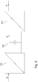
- FIG. 7 shows a variant in which the switch 290 switches a resistor R between two of the phase conductors to achieve an energy extraction, which in turn causes a rotation of the nacelle 110.
- the remarks in connection with the FIG. 4 apply in this variant according to FIG. 7 corresponding.
- the variant according to FIG. 7 can thus also in the embodiments according to the Figures 2 and 3 be used.
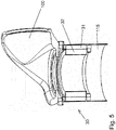
- FIG. 5 shows an embodiment of a possible mechanical structure for the rotary transformer 30 according to FIG. 2 , It can be seen from the rotary transformer 30, the primary three-phase coil system 31 and the secondary three-phase coil system 32nd
- Embodiments may (but do not have to) have one or more of the following characteristics or features, depending on the embodiment: It is possible to use the Drehübertragerkals together with a Mehrsystemumrichter for power transmission of nacelle in the tower and thus to the grid connection point and rotation of the nacelle by appropriate positional angle-dependent current component of the main inverter to generate a tangential torque within the Drehübertragers while using the Drehübertragers as Umrichter-Mittelschreibstrafo.
- the rotary transformer is preferably arranged between gondola and tower head as an assembly with a mechanical tower flange, a mechanical gondola flange, a medium voltage connection on the tower flange, low voltage connections on the gondola flange, preferably with two mechanical bearings (eg ball slewing connectors) to ensure the air gap between the stator and the tower Rotor and a capacitive transmission system for data.
- two mechanical bearings eg ball slewing connectors
- One or more rotary joints may be disposed between the tower head and the gondola shaft such that a tangential air gap moment rotates the gondola in one direction or the other depending on the direction and magnitude of that torque or against external force acting on the wind turbine rotor or nacelle accelerating acts.
- a correspondingly provided superimposed attitude control makes it possible to position the nacelle to the tower or to guide it to the new position.
- the rotary transformer (s) can take over the function of the medium-voltage transformers which connect the converters or converter systems to the mains.
- the rotary transformer may include, in addition to the inductive transmission system (s), one or more capacitive transmission systems capable of transmitting data from the stationary tower to the rotatable nacelle.
- the rotary joints may include, in addition to the secondary three-phase coil system (s), one or more secondary three-phase coil systems which supply additional energy consumers required in the nacelle separately from the main converter system with the necessary voltage (s).
- the generation of the torque can be done by the mains side inverter.
- the necessary torque can also be achieved by closing a switch (see switch 290 in the FIGS. 4 and 7 ) respectively.
- the two short-circuited or resistively loaded phases of the secondary system act like a short-circuit cage of an asynchronous motor. The result is a starting torque that accelerates the nacelle in the direction of the rotating field.
- the switch variant can after FIG. 4 or FIG. 7 be used accordingly for both directions of rotation.
Description
Die Erfindung bezieht sich auf Windenergieanlagen zum Erzeugen elektrischer Energie mit mindestens einem an einer Gondel drehbar befestigten Propeller, einem mit dem Propeller gekoppelten Generator und einem die Gondel tragenden Turm, wobei die Gondel relativ zum Turm drehbar ist.The invention relates to wind turbines for generating electrical energy with at least one rotatably mounted on a nacelle propeller, coupled to the propeller generator and a nacelle-bearing tower, wherein the nacelle is rotatable relative to the tower.
Bei herkömmlichen Windenergieanlagen erfolgt ein Drehen der Gondel relativ zum Turm mittels Direktantrieben, Hybridantrieben oder mehrstufigen Getrieben. Die Energieübertragung zwischen Gondel und Turm erfolgt üblicherweise mittels Kabel.In conventional wind turbines, the nacelle is rotated relative to the tower by means of direct drives, hybrid drives or multi-stage transmissions. The transmission of energy between the nacelle and the tower usually takes place by means of cables.
Aus den Druckschriften
Der Erfindung liegt die Aufgabe zugrunde, eine Windenergieanlage der oben beschriebenen Art hinsichtlich der Schnittstelle zwischen Gondel und Turm zu verbessern.The invention has for its object to improve a wind turbine of the type described above in terms of the interface between the nacelle and tower.
Diese Aufgabe wird erfindungsgemäß durch eine Windenergieanlage mit den Merkmalen gemäß Patentanspruch 1 gelöst. Vorteilhafte Ausgestaltungen der erfindungsgemäßen Windenergieanlage sind in Unteransprüchen angegeben.This object is achieved by a wind turbine with the features of claim 1. Advantageous embodiments of the wind turbine according to the invention are specified in subclaims.
Ein wesentlicher Vorteil der erfindungsgemäßen Windenergieanlage ist darin zu sehen, dass bei dieser ein elektromagnetischer Drehübertrager angeordnet ist. Ein solcher Drehübertrager ermöglicht zum einen ein beliebiges Drehen der Gondel um den Turm, ohne dass ein Zurückdrehen nötig ist, also anders als bei herkömmlichen Windenergieanlagen mit Kabelschnittstelle zwischen Gondel und Turm.A significant advantage of the wind power plant according to the invention is the fact that in this an electromagnetic rotary transformer is arranged. Such a rotary transformer On the one hand, it allows you to turn the nacelle around the tower without having to turn it back, unlike conventional wind turbines with a cable interface between the nacelle and the tower.
Darüber hinaus kann der Drehübertrager dazu verwendet werden, das Spannungsniveau an der Ausgangsseite des Generators an das Spannungsniveau eines mit Energie zu speisenden Energieübertragungsnetzes anzupassen. Beispielsweise ist es möglich, mittels des Drehübertragers die vom Generator üblicherweise erzeugte Niederspannung bzw. üblicherweise nur kleine Mittelspannung (im allgemeinen bis maximal 4 kV) auf ein höheres Mittelspannungsniveau hoch zu transformieren, beispielsweise auf ein Mittelspannungsniveau von 20 kV. Durch ein solches Hochtransformieren ist es möglich, im Turmbereich, also vom Fundament der Windenergieanlage bis zur Schnittstelle zwischen Gondel und Turmspitze eine vom Querschnitt her relativ dünne Energieübertragungsleitung einzusetzen.In addition, the rotary transformer can be used to adapt the voltage level on the output side of the generator to the voltage level of an energy transmission network to be fed with energy. For example, it is possible by means of the rotary transformer to transform the low voltage usually generated by the generator or usually only small mean voltage (generally up to a maximum of 4 kV) to a higher medium voltage level, for example to a medium voltage level of 20 kV. By such a step-up, it is possible to use in the tower area, so from the base of the wind turbine to the interface between the nacelle and the top of a relatively thin cross-section energy transmission line.
Ein weiterer wesentlicher Vorteil der erfindungsgemäßen Windenergieanlage besteht darin, dass durch eine geeignete elektrische Ansteuerung des Drehübertragers zwischen der Primärseite und der Sekundärseite durch den Drehübertrager ein Drehmoment erzeugt werden kann, durch das sich die Gondel relativ zum Turm verschwenken lässt. Mit anderen Worten kann der Drehübertrager eine doppelte Funktion ausüben: Zum einen kann er ein Hochtransformieren bzw. eine Veränderung des Spannungsniveaus zwischen der Ausgangsspannung des Generators und dem zu speisenden Energieübertragungsnetz vornehmen, und zum anderen kann er ein Drehmoment zum Verschwenken der Gondel bereitstellen, wenn dies gewünscht ist. Ein separater Gondelantrieb ist somit bei der erfindungsgemäßen Windenergieanlage nicht notwendig.Another significant advantage of the wind power plant according to the invention is that a torque can be generated by a suitable electrical control of the rotary transformer between the primary side and the secondary side by the rotary transformer, through which the nacelle can be pivoted relative to the tower. In other words, the rotary transformer can perform a dual function: firstly, it can make an up-conversion or a voltage level change between the output voltage of the generator and the energy transmission network to be fed, and secondly, it can provide a torque for pivoting the nacelle, if so is desired. A separate nacelle drive is thus not necessary in the wind turbine according to the invention.
Bei dem Drehübertrager handelt es sich vorzugsweise um einen elektrischen Transformator, bei dem die Primärseite gegenüber der Sekundärseite gedreht werden kann.The rotary transformer is preferably an electrical transformer in which the primary side can be rotated relative to the secondary side.
Der Drehübertrager umfasst bevorzugt mindestens ein primäres Drehstromspulensystem und mindestens ein sekundäres Drehstromspulensystem, die jeweils paarweise über einen Spalt mechanisch voneinander getrennt, aber magnetisch miteinander gekoppelt sind.The rotary transformer preferably comprises at least one primary three-phase current coil system and at least one secondary three-phase current coil system, which are mechanically separated from each other in pairs via a gap, but are magnetically coupled to one another.
Auf der Primärseite des Drehübertragers bilden vorzugsweise elektrische Spulenpakete in Form von Spulenringsegmenten mindestens ein ringförmiges primäres Drehstromspulensystem, das unter Bildung mindestens eines ringförmigen Luftspaltes mindestens einem ringförmigen sekundären Drehstromspulensystem auf der Sekundärseite gegenüberliegt. Das ringförmige sekundäre Drehstromspulensystem wird vorzugsweise ebenfalls durch elektrische Spulenpakete in Form von Spulenringsegmenten gebildet; diese liegen denen des primären Drehstromspulensystems gegenüber. Die Drehstromspulensysteme sind vorzugsweise dreiphasig oder aber mindestens dreiphasig.On the primary side of the rotary transformer preferably form electrical coil packages in the form of coil ring segments at least one annular primary three-phase current coil system which faces at least one annular secondary air-current coil system on the secondary side to form at least one annular air gap. The annular secondary three-phase current coil system is preferably also formed by electrical coil packages in the form of coil ring segments; these are opposite those of the primary three-phase coil system. The three-phase coil systems are preferably three-phase or at least three-phase.
Die Wicklungszahl auf der Primärseite des Drehübertragers und die auf der Sekundärseite des Drehübertragers sind vorzugsweise derart gewählt, dass die auf der Sekundärseite erzeugte Sekundärspannung größer als die auf der Primärseite eingespeiste Primärspannung ist.The number of windings on the primary side of the rotary transformer and that on the secondary side of the rotary transformer are preferably chosen such that the secondary voltage generated on the secondary side is greater than the primary voltage fed in on the primary side.
Die Primärspannung auf der Primärseite des Drehübertragers liegt vorzugsweise im Bereich zwischen 100 V und 4 kV.The primary voltage on the primary side of the rotary transformer is preferably in the range between 100 V and 4 kV.
Das Übertragungsverhältnis des Drehübertragers ist bevorzugt derart gewählt, dass die Sekundärspannung auf der Sekundärseite im Bereich zwischen 10 und 100 kV liegt.The transmission ratio of the rotary transformer is preferably selected such that the secondary voltage on the secondary side is in the range between 10 and 100 kV.
Der Umrichter ist neben seiner Grundfunktion, die im Generator erzeugte elektrische Energie an die Netzeinspeisung anzupassen und zu übertragen vorzugsweise derart ausgestaltet, dass er den in die Primärseite des Drehübertragers eingespeisten Strom derart einstellen kann, dass der Drehübertrager ein mechanisches Drehmoment zum Drehen der Gondel relativ zum Turm erzeugen kann. Das entsprechende Einstellen des Stromes kann beispielsweise durch Wahl der Amplitude, Frequenz und/oder Phasenlage des in den Drehübertrager eingespeisten Speisestromes relativ zur Amplitude, Frequenz und/oder Phasenlage des zu speisenden Energieübertragungsnetzes erfolgen.In addition to its basic function of adapting and transmitting the electrical energy generated in the generator to the mains supply, the converter is preferably configured such that it can set the current fed into the primary side of the rotary transformer such that the rotary transformer generates a mechanical torque for rotating the nacelle relative to the rotor Can generate tower. The corresponding adjustment of the current can be effected, for example, by selecting the amplitude, frequency and / or phase position of the feed current fed into the rotary transformer relative to the amplitude, frequency and / or phase position of the energy transmission network to be fed.
Beispielsweise kann die Steuereinrichtung den Umrichter derart ansteuern, dass dieser den in die Primärseite des Dreh übertragers eingespeisten Strom derart einstellt, dass der Drehübertrager ein mechanisches Drehmoment zum Drehen der Gondel relativ zum Turm erzeugt. Das entsprechende Einstellen des Stromes kann die Steuereinrichtung beispielsweise durch Wahl der Amplitude, Frequenz und/oder Phasenlage des in den Drehübertrager eingespeisten Stromes relativ zur Amplitude, Frequenz und/oder Phasenlage des zu speisenden Energieübertragungsnetzes vornehmen.For example, the control device to drive the inverter such that this in the primary side of the rotation transformer supplied power sets such that the rotary transformer generates a mechanical torque for rotating the nacelle relative to the tower. The corresponding adjustment of the current, the control device, for example, by selecting the amplitude, frequency and / or phase of the current injected into the rotary transformer current relative to the amplitude, frequency and / or phase position of the energy transmission network to be fed.
Alternativ oder zusätzlich kann die Steuereinrichtung (zum Beispiel mittels eines Schalters oder eines geschalteten Widerstands) einem Zwischenkreis des Umrichters oder einem Zwischenkreis eines Umrichterzweigs des Umrichters Energie entnehmen, um ein Drehmoment zu erzeugen. Dabei wird eine zusätzliche asynchrone drehmomentenbildende Drehfeldkomponente im Luftspalt des Drehübertragers gebildet gemäß der Wirkungsweise eines Asynchronkäfigläufers bzw. eines Asynchroschleifringläufers, die ein Drehmoment erzeugt, welches die Gondel beschleunigt.Alternatively or additionally, the control device can take energy (for example by means of a switch or a switched resistor) from an intermediate circuit of the converter or from an intermediate circuit of a converter branch of the converter in order to generate a torque. In this case, an additional asynchronous torque-forming rotating field component is formed in the air gap of the rotary transformer according to the operation of an Asynchronkäfigläufers or an Asynchroschleifringläufers that generates a torque that accelerates the nacelle.
Alternativ oder zusätzlich kann die Steuereinrichtung - in einem Bereich zwischen dem Umrichterausgang und der Primärseite des Drehübertragers - mittels eines oder mehrerer elektrischer Schalter Phasen einer drei- oder mehrphasigen primärseitigen Anschlussleitung, die den Drehübertrager primärseitig speist, kurzschließen oder widerstandsmäßig belasten gemäß der Wirkungsweise eines Asynchronkäfigläufers bzw. eines Asynchroschleifringläufers, um eine Drehung zu verursachen.Alternatively or additionally, the control device - in one area between the converter output and the primary side of the rotary transformer - short circuit or resistance load by means of one or more electrical switch phases of a three- or multi-phase primary-side connection line, which feeds the rotary transformer primary side according to the mode of action of an Asynchronkäfigläufers or an asynchronous slip ring rotor to cause a rotation.
Wenn die im Turm verlegte elektrische Leitung mit einem externen Energieübertragungsnetz mit einer vorgegebenen Netzfrequenz in Verbindung steht, ist es besonders vorteilhaft, wenn der Umrichter einen zusätzlichen Primärstrom, vorzugsweise dem Haupteinspeisestrom überlagert in den Drehübertrager einspeist, dessen Frequenz von der Netzfrequenz abweicht, wenn der Drehübertrager ein Drehmoment zum Drehen der Gondel relativ zum Turm erzeugen soll; dies führt zu einem magnetischen Schlupf zwischen dem primären Drehstromspulensystem und dem sekundären Drehstromspulensystem und somit analog zu einer Asynchronmaschine zu einem Drehmoment.When the electrical cable laid in the tower is in communication with an external power transmission network having a predetermined power frequency, it is particularly advantageous when the inverter feeds an additional primary current, preferably superimposed on the main supply current, into the rotary transformer whose frequency deviates from the mains frequency when the rotary transformer is to generate a torque for rotating the nacelle relative to the tower; this leads to a magnetic slip between the primary three-phase coil system and the secondary three-phase current coil system and thus analogous to an asynchronous machine to a torque.
Bei einer bevorzugten Ausgestaltung ist vorgesehen, dass der Umrichter zumindest zwei Umrichterzweige aufweist, die jeweils einen Primärteilstrom erzeugen, der Drehübertrager zumindest zwei Drehübertragereinheiten aufweist, die jeweils ein primäres Drehstromspulensystem und ein mit diesem gekoppeltes sekundäres Drehstromspulensystem umfassen, die Drehübertragereinheiten eingangsseitig jeweils von einem der Umrichterzweige gespeist werden und ausgangsseitig jeweils mit der im Turm verlegten elektrischen Leitung in Verbindung stehen, und der Drehübertrager ein Drehmoment zur Drehung der Gondel relativ zum Turm hervorruft, falls von den Drehübertragereinheiten erzeugte Drehmomente ein Summendrehmoment ungleich Null erzeugen.In a preferred embodiment, it is provided that the converter has at least two converter branches which each generate a primary partial current, the rotary transformer has at least two rotary transformer units, each comprising a primary three-phase coil system and a coupled with this secondary three-phase coil system, the rotary transmitter units on the input side of each of the Umrichtzweige be energized and the output side in each case with the laid in the tower electrical line in communication, and the rotary transformer causes a torque for rotation of the nacelle relative to the tower, if generated by the rotary transmitter units generate a non-zero sum torque.
Bei der letztgenannten Variante ist es von Vorteil, wenn eine der Drehübertragereinheiten ein rechtsdrehendes Drehfeldsystem und ein anderes ein linksdrehendes Drehfeldsystem erzeugt. Die Steuereinrichtung und der Umrichter legen bei dieser Ausgestaltung vorzugsweise die Drehrichtung der Gondel fest, indem sie gezielt das rechtsdrehende Drehfeldsystem und das linksdrehende Drehfeldsystem in unterschiedlichem Maß mit Energie versorgen bzw. "bevorzugen".In the latter variant, it is advantageous if one of the rotary transmitter units generates a clockwise rotating field system and another a left-handed rotating field system. In this embodiment, the control device and the converter preferably determine the direction of rotation of the nacelle by selectively supplying or "favoring" the clockwise rotating field system and the left-handed rotating field system with energy to varying degrees.
Die Erfindung bezieht sich darüber hinaus auf ein Verfahren zum Betreiben einer Windenergieanlage zum Erzeugen elektrischer Energie, wobei die Windenergieanlage einen an einer Gondel drehbar befestigten Propeller, einen mit dem Propeller gekoppelten Generator und einen die Gondel tragenden Turm aufweist, wobei die Gondel relativ zum Turm drehbar ist.The invention further relates to a method of operating a wind turbine for generating electrical power, the wind turbine comprising a propeller rotatably mounted on a nacelle, a generator coupled to the propeller and a tower supporting the nacelle, the nacelle being rotatable relative to the tower is.
Erfindungsgemäß ist bezüglich eines solchen Verfahrens vorgesehen, dass zwischen der Gondel und dem Turm ein elektromagnetischer Drehübertrager angeordnet ist und die von dem Generator erzeugte elektrische Energie mittels des Drehübertragers in eine im Turm verlegte elektrische Leitung eingespeist wird.According to the invention, it is provided with respect to such a method that an electromagnetic rotary transformer is arranged between the nacelle and the tower and the electrical energy generated by the generator is fed by means of the rotary transformer into an electrical line laid in the tower.
Bezüglich der Vorteile des erfindungsgemäßen Verfahrens sei auf die obigen Ausführungen verwiesen.With regard to the advantages of the method according to the invention, reference is made to the above statements.
Vorteilhaft ist es, wenn die Gondel relativ zum Turm gedreht wird, indem mit einem zwischen dem Generator und dem Drehübertrager elektrisch angeordneten Umrichter der in die Primärseite des Drehübertragers eingespeiste Strom - beispielsweise durch Wahl von Amplitude, Frequenz oder Phase - derart eingestellt wird, dass der Drehübertrager ein mechanisches Drehmoment zum Drehen der Gondel relativ zum Turm erzeugt.It is advantageous if the nacelle is rotated relative to the tower by using an electrically connected between the generator and the rotary transformer inverter fed into the primary side of the rotary transformer current - for example by selection of amplitude, frequency or phase - is set such that the Rotary transformer generates a mechanical torque for rotating the nacelle relative to the tower.
Alternativ oder zusätzlich kann vorgesehen sein, dass zum Erzeugen eines Drehmoments zum Verdrehen der Gondel zwischen ausgewählten Phasen der den Drehübertrager speisenden mehrphasigen Speiseleitung ein Kurzschluss erzeugt oder zwischen die Phasen ein Widerstand zwischengeschaltet wird, wodurch das primäre Magnetfeld modifiziert und ein Schlupf zwischen Primärfeld und Sekundärfeld hervorgerufen wird.Alternatively or additionally, it may be provided that generated to generate a torque for rotating the nacelle between selected phases of the rotary transformer feeding multiphase feed line, a short circuit or between the phases a resistor is interposed, whereby the primary magnetic field modified and caused a slip between the primary field and secondary field becomes.
Alternativ oder zusätzlich kann bei Drehübertragern mit zwei oder mehr Drehübertragereinheiten vorgesehen sein, dass zum Erzeugen eines Drehmoments zum Verdrehen der Gondel bei einem oder mehreren ausgewählten Drehübertragereinheiten primärseitig weniger Speiseenergie zur Verfügung gestellt wird als bei zumindest einer anderen Drehübertragereinheit. Dies kann in vorteilhafter Weise durch Energieentnahme in zugeordneten Umrichterzweigen oder durch Energieentnahme zwischen den Umrichterzweigen und der jeweiligen Drehübertragereinheit geschehen.Alternatively or additionally, it may be provided in the case of rotary transmitters with two or more rotary transmitter units that, for one or more selected rotary transmitter units, less supply energy is provided on the primary side to generate a torque for rotating the nacelle than at least one other rotary transmitter unit. This can be done in an advantageous manner by energy extraction in associated inverter branches or by energy removal between the inverter branches and the respective rotary transmitter unit.
Die Erfindung wird nachfolgend anhand von Ausführungsbeispielen näher erläutert; dabei zeigen beispielhaft
- Figur 1
- ein Ausführungsbeispiel für eine erfindungsgemäße Windenergieanlage in einer schematischen Sicht von vorn,
- Figur 2
- ein Ausführungsbeispiel für einen Umrichter und einen Drehübertrager, die für die Windenergieanlage gemäß
Figur 1 geeignet sind, - Figur 3
- ein weiteres Ausführungsbeispiel für einen Umrichter und einen Drehübertrager, die bei der Windenergieanlage gemäß
Figur 1 eingesetzt werden können, - Figur 4
- ein Ausführungsbeispiel für einen Schalter zum Kurzschließen zweier Phasen an der Primärseite eines Drehübertragers zum Zwecke der Drehmomenterzeugung,
- Figur 5
- in einer dreidimensionalen aufgeschnittenen Sicht einen möglichen mechanischen Aufbau einer Windenergieanlage, der bei dem Ausführungsbeispiel gemäß Figur 2 eingesetzt werden kann,
- Figur 6
- ein Ausführungsbeispiel für einen möglichen internen Aufbau des Umrichters gemäß
Figur 2 , - Figur 7
- ein Ausführungsbeispiel für einen Schalter zum Zuschalten eines Widerstands zwischen zwei Phasen an der Primärseite eines Drehübertragers zum Zwecke der Drehmomenterzeugung.
- FIG. 1
- An embodiment of a wind turbine according to the invention in a schematic view from the front,
- FIG. 2
- An exemplary embodiment of an inverter and a rotary transformer, which for the wind turbine according to
FIG. 1 are suitable, - FIG. 3
- a further embodiment of an inverter and a rotary transformer, in the wind turbine according to
FIG. 1 can be used - FIG. 4
- an exemplary embodiment of a switch for short-circuiting two phases on the primary side of a rotary transformer for the purpose of torque generation,
- FIG. 5
- in a three-dimensional cutaway view of a possible mechanical structure of a wind turbine, which can be used in the embodiment according to FIG. 2,
- FIG. 6
- an embodiment of a possible internal structure of the inverter according to
FIG. 2 . - FIG. 7
- an embodiment of a switch for connecting a resistor between two phases on the primary side of a rotary transformer for the purpose of torque generation.
In den Figuren werden der Übersicht halber für identische oder vergleichbare Komponenten stets dieselben Bezugszeichen verwendet.For the sake of clarity, the same reference numbers are always used in the figures for identical or comparable components.
Die
Die Gondel 110 wird von einem Turm 115 getragen, und zwar derart, dass die Gondel 110 um die in der
Die
In der
Der Drehübertrager 30 weist eine Primärseite auf, die in der
Auf der Primärseite PS des Drehübertrager 30 bilden aus Gründen der Übersicht nicht näher gezeigte elektrische Spulenpakete in Form von Spulenringsegmenten vorzugsweise mindestens ein ringförmiges primäres Drehstromspulensystem, das unter Bildung mindestens eines ringförmigen Luftspaltes mindestens einem ringförmigen sekundären Drehstromspulensystem gegenüberliegt. Das ringförmige sekundäre Drehstromspulensystem wird ebenfalls durch elektrische Spulenpakete in Form von Spulenringsegmenten gebildet; diese liegen denen des primären Drehstromspulensystems gegenüber. Die Drehstromspulensysteme sind vorzugsweise dreiphasig oder aber mindestens dreiphasig.On the primary side PS of the
Die
Es lässt sich in der
Das primäre Drehstromspulensystem 31 und das sekundäre Drehstromspulensystem 32 sind derart aufeinander abgestimmt, dass das Übersetzungsverhältnis größer als 1 ist und somit die auf der Sekundärseite SS erzeugte Sekundärspannung größer als die auf der Primärseite eingespeiste Primärspannung ist. Ein solches Verhalten kann durch geeignete Wicklungszahlverhältnisse auf der Primärseite PS und der Sekundärseite SS erreicht werden. Vorzugsweise ist der Drehübertrager 30 derart ausgelegt, dass die Primärseite PS mit einer Primärspannung zwischen 100 V und 4 kV betrieben werden kann. Das Übersetzungsverhältnis des Drehübertragers 30 ist dabei vorzugsweise derart gewählt, dass die Sekundärspannung auf der Sekundärseite im Bereich einer Mittelspannung, vorzugsweise zwischen 10 und 100 kV liegt. Besonders bevorzugt beträgt die Mittelspannung 20 kV, da eine solche Spannung bei Energieversorgungsnetzen üblich ist.The primary three-
Durch die beschriebene Ausgestaltung des Drehübertragers 30 lässt sich erreichen, dass dieser als elektrischer Transformator arbeitet, der die vom Generator 120 erzeugte elektrische Spannung, bei der es sich üblicherweise um eine Nieder- bzw. Mittelspannung handelt, auf ein höheres Niveau, wie beispielsweise eine Mittelspannung von 20 kV, hochtransformiert.As a result of the described configuration of the
Zusätzlich zu der Funktion eines elektrischen Transformators dient der Drehübertrager dazu, ein Drehen der drehbaren Gondel 110 entlang der Pfeilrichtung ϕ in
Im Normalbetrieb, wenn die drehbare Gondel 110 nicht verschwenkt werden soll, wird die Steuereinrichtung 40 den Umrichter 20 derart ansteuern, dass der in den Drehübertrager 30 über die Leitung 118 eingespeiste bzw. umgerichtete Strom Ie von seiner Frequenz her der Netzfrequenz des externen E-nergieübertragungsnetzes 900 (siehe
Soll hingegen die drehbare Gondel 110 verschwenkt werden, so kann die Steuereinrichtung 40 den Umrichter 20 derart ansteuern, dass der umgerichtete Strom Ie von seiner Frequenz bzw. Phasenlage nicht mehr der Netzfrequenz des externen Energieübertragungsnetzes 900 entspricht. In einem solchen Fall wird der Drehübertrager 30 aufgrund des Schlupfes (wie bei einer Asynchronmaschine) zwischen den Magnetfeldern des primären Drehstromspulensystems 31 und des sekundären Drehstromspulensystems 32 ein Drehmoment erzeugen, das zu einem Verschwenken der Gondel 110 relativ zum Turm 115 führt.If, on the other hand, the
Mit anderen Worten besteht die Funktion des Drehübertragers 30 gemäß
Wie weiter unten noch näher im Zusammenhang mit der
Alternativ kann anstelle eines Kurzschließens durch Zuschalten eines Widerstandes R bei zwei der Phasenleiter Energie bzw. Leistung entnommen werden; dies zeigt beispielhaft die
Die
Die
Bei dem Ausführungsbeispiel gemäß
Die beiden Umrichterzweige 21 und 22 erzeugen jeweils umgerichtete Ströme Ie1 und Ie2, die über zugeordnete mehrphasige, vorzugsweise dreiphasige, Anschlussleitungen 180 bzw. 181 in den Drehübertrager 30 eingespeist werden.The two Umrichterzweige 21 and 22 respectively generate converted currents Ie1 and Ie2, which are fed via associated multi-phase, preferably three-phase, connecting
Der Drehübertrager 30 weist bei dem Ausführungsbeispiel gemäß
Die erste Drehübertragereinheit 250 umfasst ein erstes primäres Drehstromspulensystem 230 und ein erstes sekundäres Drehstromspulensystem 240.The first
Die zweite Drehübertragereinheit 280 umfasst ein zweites primäres Drehstromspulensystem 260 und ein zweites sekundäres Drehstromspulensystem 270.The second
Die beiden Drehübertragereinheiten 250 und 280 sind vorzugsweise hinsichtlich ihrer Magnetfelddrehrichtungen unterschiedlich: So kann beispielsweise die erste Drehübertragereinheit 250 mit einem rechts drehenden Drehfeldsystem arbeiten und die zweite Drehübertragereinheit 280 mit einem links drehenden.The two
Ausgangsseitig stehen die beiden Drehübertragereinheiten 250 und 280 mit Ausgangsleitungen 210 und 220 in Verbindung, die mit der Energieübertragungsleitung 117 gemäß
Die Drehübertragereinheiten 250 und 280 sind - wie erwähnt - vorzugsweise drei- oder mehrphasig; entsprechendes gilt für ihre primären und sekundären Drehstromspulensysteme. Auch die Leitungen 210 und 220 weisen die entsprechende Phasenzahl auf und sind demgemäß entsprechend drei- oder mehrphasig. Auch die Energieübertragungsleitung 117 weist die entsprechende Phasenzahl, beispielsweise drei Phasen, auf.The
Die beiden Umrichterzweige 21 und 22 werden von einer in der
Durch die Ansteuerung der beiden Umrichterzweige 21 und 22 kann die Steuereinrichtung dafür sorgen, dass der Drehübertrager 30 ein Drehmoment zum Verdrehen der drehbaren Gondel 110 entlang der einen Drehrichtung oder entlang der entgegen gesetzten Drehrichtung hervorruft. Dies kann durch entsprechende Ausgestaltung der umgerichteten Ströme Ie1 und Ie2 nach Betrag und Phase erfolgen:
- Soll kein Drehen der drehbaren Gondel 110 erfolgen, so ist die Phasenlage zwischen den umgerichteten Strömen Ie1 und Ie2 beispielsweise vorzugsweise gleich 180°, und die Amplituden der umgerichteten Ströme Ie1 und Ie2 sind gleich groß.
- Soll ein Drehen der drehbaren Gondel 110 erfolgen, so kann dies beispielsweise dadurch hervorgerufen werden, dass die Phasenlage zwischen den umgerichteten Strömen Ie1 und Ie2 verändert und/oder die Amplituden der umgerichteten Ströme Ie1 und Ie2 unterschiedlich eingestellt werden.
- If no rotation of the
rotatable nacelle 110 takes place, then the phase position between the straightened currents Ie1 and Ie2 is for example preferably equal to 180 °, and the amplitudes of the straightened currents Ie1 and Ie2 are the same. - If rotation of the
rotatable nacelle 110 is to take place, this may be caused, for example, by the phase position between the transposed currents Ie1 and Ie2 being changed and / or the amplitudes of the reversed currents Ie1 and Ie2 being set differently.
Ein Drehen der drehbaren Gondel 110 kann bei der Ausführungsvariante gemäß
Die
Im Zusammenhang mit der
Die
Alternativ (oder zusätzlich) kann der Schalter 290 (oder ein weiterer Schalter 290) auch zwischen dem zweiten Umrichterzweig 22 und der zweiten Drehübertragereinheit 280 angeordnet sein; das Prinzip der Drehmomenterzeugung gilt dann entsprechend.Alternatively (or additionally), the switch 290 (or another switch 290) may also be disposed between the
Im Übrigen ist es möglich, einen Schalter 290 auch in der dreiphasigen Leitung 118 zwischen dem Umrichter 20 und der Primärseite PS des Drehübertragers 30 gemäß
Die
Die
Zusammengefasst sind oben im Zusammenhang mit den
Möglich ist die Nutzung des Drehübertragerprinzips zusammen mit einem Mehrsystemumrichter zur Energieübertragung von Gondel in den Turm und damit zum Netzanschlusspunkt und gleichzeitiger Drehung der Gondel durch entsprechende lagewinkelabhängige Stromkomponente der Hauptumrichters zur Erzeugung eines tangentialen Drehmomentes innerhalb des Drehübertragers bei gleichzeitiger Nutzung des Drehübertragers als Umrichter-Mittelspannungstrafo. Angeordnet wird der Drehübertrager vorzugsweise zwischen Gondel und Turmkopf als Baugruppe mit einem mechanischen Turmflansch, einem mechanischen Gondelflansch, einem Mittelspannungsanschluss am Turmflansch, Niederspannungsanschlüsse am Gondelflansch, mit vorzugsweise zwei mechanischen Lagern (z. B. Kugeldrehverbinder) zur Sicherstellung des Luftspaltes zwischen dem Stator und dem Rotor und einem kapazitiven Übertragungssystem für Daten.In summary, above are related to the
It is possible to use the Drehübertragerprinzips together with a Mehrsystemumrichter for power transmission of nacelle in the tower and thus to the grid connection point and rotation of the nacelle by appropriate positional angle-dependent current component of the main inverter to generate a tangential torque within the Drehübertragers while using the Drehübertragers as Umrichter-Mittelspannungstrafo. The rotary transformer is preferably arranged between gondola and tower head as an assembly with a mechanical tower flange, a mechanical gondola flange, a medium voltage connection on the tower flange, low voltage connections on the gondola flange, preferably with two mechanical bearings (eg ball slewing connectors) to ensure the air gap between the stator and the tower Rotor and a capacitive transmission system for data.
Damit entfallen die klassischen Trafos im Turm oder in der Gondel, die Azimutantriebe und die entsprechenden Antriebe (Drives) mit Schaltschränken und Schaltgeräten. Die Gondel kann ohne Begrenzung dem Wind nachgeführt werden, ohne dass nach dem Erreichen der Winkelgrenze zurückgedreht werden muss. Der Leistungskabelloop (Leistungskabelschleife) entfällt total. Man kann mittels Schienen mit Mittelspannung im Turm operieren. Die Bereitstellung von Kommutierungsinduktivität des "Drehübertragertrafos" ist in großen Bereichen möglich. Modularität und mehrere Systeme sowohl auf der Mittelspannungsseite, als auch auf der Niederspannungsseite sind möglich. Für die Erzeugung des Gondeldrehmomentes kann lediglich Software genutzt werden, Stellglied ist der Generatorumrichter. Diese zusätzliche Antriebsleistung zum Drehen muss dieser auch bei der Lösung mit separaten Yaw-Antrieben ohnehin bereitstellen.This eliminates the classic transformers in the tower or in the nacelle, the azimuth drives and the corresponding drives (drives) with control cabinets and switchgear. The nacelle can be tracked without limitation to the wind, without having to turn back after reaching the angle limit. The power cable loop (power cable loop) is completely eliminated. You can operate with medium voltage rails in the tower. The provision of commutation inductance of the "rotary transformer" is possible in large areas. Modularity and several systems both on the medium voltage side and on the low voltage side are possible. For the generation of the nacelle torque only software can be used, actuator is the generator converter. This additional drive power for turning must provide this anyway with the solution with separate Yaw drives anyway.
Ein oder mehrere Drehübertrager können so zwischen Turmkopf und Gondelschaft angeordnet werden, dass ein tangentiales Luftspaltmoment die Gondel je nach Richtung und Stärke dieses Drehmomentes in die eine oder andere Richtung dreht oder entgegen einer äußeren Kraft, die auf den Windanlagenrotor oder das Gondelgehäuse einwirkt, bremsend oder beschleunigend wirkt.One or more rotary joints may be disposed between the tower head and the gondola shaft such that a tangential air gap moment rotates the gondola in one direction or the other depending on the direction and magnitude of that torque or against external force acting on the wind turbine rotor or nacelle accelerating acts.
Eine entsprechend vorgesehene überlagerte Lageregelung lässt es zu, die Gondel zum Turm zu positionieren bzw. zur neuen Position hinzuführen.A correspondingly provided superimposed attitude control makes it possible to position the nacelle to the tower or to guide it to the new position.
Der oder die Drehübertrager können die Funktion der Mittelspannungstrafos übernehmen, die die Umrichter bzw. Umrichtersysteme mit dem Netz verbinden.The rotary transformer (s) can take over the function of the medium-voltage transformers which connect the converters or converter systems to the mains.
Die Drehübertrager kann neben dem induktiven Übertragungssystem/en kann auch ein oder mehrere kapazitive Übertragungssysteme beinhalten, die Daten vom stehenden Turm auf die drehbare Gondel übertragen können.The rotary transformer may include, in addition to the inductive transmission system (s), one or more capacitive transmission systems capable of transmitting data from the stationary tower to the rotatable nacelle.
Die Drehübertrager können zusätzlich zum sekundären Drehstromspulensystem/en noch ein oder mehrere sekundäre Drehstromspulensysteme beinhalten, die zusätzliche in der Gondel notwendige Energieverbraucher mit der entsprechenden notwendigen Spannung/en getrennt von dem Hauptumrichtersystem versorgt.The rotary joints may include, in addition to the secondary three-phase coil system (s), one or more secondary three-phase coil systems which supply additional energy consumers required in the nacelle separately from the main converter system with the necessary voltage (s).
Die Erzeugung des Drehmoments kann durch den netzseitigen Umrichter erfolgen.The generation of the torque can be done by the mains side inverter.
Das notwendige Drehmoment kann auch durch Schließen eines Schalters (siehe Schalter 290 in den
Werden zwei Drehübertrager verwendet, bei dem ein Drehübertrager mittels Rechtsdrehfeld betrieben wird, der andere mit einem Linksdrehfeld betrieben wird, kann die Schaltervariante nach
Obwohl die Erfindung im Detail durch bevorzugte Ausführungsbeispiele näher illustriert und beschrieben wurde, so ist die Erfindung nicht durch die offenbarten Beispiele eingeschränkt und andere Variationen können vom Fachmann hieraus abgeleitet werden, ohne den Schutzumfang der Erfindung zu verlassen.While the invention has been further illustrated and described in detail by way of preferred embodiments, the invention is not limited by the disclosed examples, and other variations can be derived therefrom by those skilled in the art without departing from the scope of the invention.
- 1010
- WindenergieanlageWind turbine
- 2020
- Umrichterinverter
- 2121
- UmrichterzweigUmrichterzweig
- 2222
- UmrichterzweigUmrichterzweig
- 3030
- DrehübertragerRotary joint
- 3131
- DrehstromspulensystemThree-phase coil system
- 3232
- DrehstromspulensystemThree-phase coil system
- 4040
- Steuereinrichtungcontrol device
- 100100
- Propellerpropeller
- 110110
- Gondelgondola
- 115115
- Turmtower
- 116116
- Drehlagerpivot bearing
- 117117
- Leitungmanagement
- 118118
- Leitungmanagement
- 120120
- Generatorgenerator
- 130130
- Umrichtereinheitinverter unit
- 140140
- Chopperwiderstandchopper resistance
- 150150
- Chopperchopper
- 160160
- GleichspannungszwischenkreisDc link
- 170170
- Umrichtereinheitinverter unit
- 180180
- Anschlussleitungconnecting cable
- 181181
- Anschlussleitungconnecting cable
- 190190
- Gondelschachtpod bay
- 200200
- Turmschachttower shaft
- 210210
- Ausgangsleitungoutput line
- 220220
- Ausgangsleitungoutput line
- 230230
- DrehstromspulensystemThree-phase coil system
- 240240
- DrehstromspulensystemThree-phase coil system
- 250250
- DrehübertragereinheitRotary transformer unit
- 260260
- DrehstromspulensystemThree-phase coil system
- 270270
- DrehstromspulensystemThree-phase coil system
- 280280
- DrehübertragereinheitRotary transformer unit
- 290290
- Schaltercounter
- 900900
- EnergieübertragungsnetzPower transmission network
- IaIa
- Ausgangsstromoutput current
- IeIe
- Stromelectricity
- Ie1Ie 1
- Stromelectricity
- Ie2ie 2
- Stromelectricity
- IgIg
- Generatorstromgenerator power
- PSPS
- Primärseiteprimary
- RR
- Widerstandresistance
- SSSS
- Sekundärseitesecondary side
- ZZ
- Vertikalevertical
- ϕφ
- Doppelpfeildouble arrow
Claims (9)
- Wind energy installation (10) for generating electrical energy comprising at least one propeller (100) fastened to a nacelle (110) such that it is able to rotate, a generator (120) coupled to the propeller (100) and a tower (115) supporting the nacelle (110), wherein the nacelle (110) is able to rotate relative to the tower (115),
wherein
an electromagnetic rotary transformer (30) is arranged between the nacelle (110) and the tower (115), said rotary transformer feeding the electrical energy generated by the generator (120) into an electrical line laid in the tower (115),
characterized in that- the wind energy installation (10) has a control device (40), which is connected to a converter (20) and actuates said converter,- wherein the control device (40) is designed in such a way that, in the case that the nacelle (110) is intended to be rotated relative to the tower (115), said control device actuates the converter (20) in such a way that the rotary transformer (30) generates a mechanical torque for rotating the nacelle (110) relative to the tower (115) and the nacelle (110) is rotated by said torque. - Wind energy installation (10) according to Claim 1,
characterized in that
the rotary transformer (30) comprises a primary three-phase coil system (31) and a secondary three-phase coil system (32), which are mechanically separated from one another by means of a gap but are magnetically coupled to one another. - Wind energy installation (10) according to either of the preceding claims,
characterized in that
the number of windings on the primary side (PS) of the rotary transformer (30) and that on the secondary side (SS) of the rotary transformer (30) are selected in such a way that the secondary voltage generated on the secondary side is greater than the primary voltage fed in on the primary side. - Wind energy installation (10) according to one of the preceding claims,
characterized in that- the primary voltage on the primary side of the rotary transformer (30) is in the range between 100 V and 4 kV and- the transformation ratio of the rotary transformer (30) is selected in such a way that the secondary voltage on the secondary side is in the range between 10 and 100 kV. - Wind energy installation (10) according to one of the preceding claims,
characterized in that
the converter (20) is electrically arranged between the generator (120) and the rotary transformer (30) and feeds the current into the primary side of the rotary transformer (30). - Wind energy installation (10) according to one of the preceding claims,
characterized in that- the electrical line (117) laid in the tower (115) is connected to an external energy transmission network (900) at a prescribed network frequency and- the converter (20) feeds a primary current into the rotary transformer (30), the frequency and/or phase angle of said primary current deviating from the network frequency or network phase angle when the rotary transformer (30) is intended to generate a torque for rotating the nacelle (110) relative to the tower (115), and thereby causes, in particular, a magnetic slip between the primary three-phase coil system (31) and the secondary three-phase coil system (32) . - Wind energy installation (10) according to one of the preceding claims,
characterized in that- the converter (20) has at least two converter branches (21, 22), which each generate a primary component current,- the rotary transformer (30) has at least two rotary transformer units (250, 280), which each comprise a primary three-phase coil system (230, 260) and a secondary three-phase coil system (240, 270) coupled thereto,- the rotary transformer units are each fed on the input side by one of the converter branches and are each connected on the output side to the electrical line laid in the tower (115), and- the rotary transformer (30) causes a torque for rotating the nacelle (110) relative to the tower (115) if torques generated by the rotary transformer units generate a total torque different from zero. - Wind energy installation (10) according to Claim 7,
characterized in that- one of the rotary transformer units generates a magnetic field system rotating clockwise and another generates a magnetic field system rotating anti-clockwise and- the control device (40) and the converter (20) determine the direction of rotation of the nacelle (110) by virtue of them generating a torque for rotating the nacelle (110) by way of the magnetic field system rotating clockwise or the magnetic field system rotating anti-clockwise. - Method for operating a wind energy installation (10) for generating electrical energy, wherein the wind energy installation (10) comprises a propeller (100) fastened to a nacelle (110) such that it is able to rotate, a generator (120) coupled to the propeller (100) and a tower (115) supporting the nacelle (110), wherein the nacelle (110) is able to rotate relative to the tower (115),
wherein- an electromagnetic rotary transformer (30) is arranged between the nacelle (110) and the tower (115) and- the electrical energy generated by the generator (120) is fed into an electrical line laid in the tower (115) by means of the rotary transformer (30),characterized in that
the nacelle (110) is rotated relative to the tower (115) by virtue of the current fed into the rotary transformer (30) using a converter (20) electrically arranged between the generator (120) and the rotary transformer (30) being set in such a way that the rotary transformer (30) generates a mechanical torque for rotating the nacelle (110) relative to the tower (115) .
Applications Claiming Priority (1)
| Application Number | Priority Date | Filing Date | Title |
|---|---|---|---|
| DE102016206395.2A DE102016206395A1 (en) | 2016-04-15 | 2016-04-15 | Wind turbine |
Publications (2)
| Publication Number | Publication Date |
|---|---|
| EP3232052A1 EP3232052A1 (en) | 2017-10-18 |
| EP3232052B1 true EP3232052B1 (en) | 2019-05-22 |
Family
ID=58501283
Family Applications (1)
| Application Number | Title | Priority Date | Filing Date |
|---|---|---|---|
| EP17165229.0A Active EP3232052B1 (en) | 2016-04-15 | 2017-04-06 | Wind energy system |
Country Status (2)
| Country | Link |
|---|---|
| EP (1) | EP3232052B1 (en) |
| DE (1) | DE102016206395A1 (en) |
Family Cites Families (4)
| Publication number | Priority date | Publication date | Assignee | Title |
|---|---|---|---|---|
| GB0513821D0 (en) * | 2005-07-06 | 2005-08-10 | Rolls Royce Plc | Transformer |
| GB0819561D0 (en) * | 2008-10-27 | 2008-12-03 | Rolls Royce Plc | A distributed electrical generation system |
| DE102010040366A1 (en) * | 2010-09-07 | 2012-03-08 | rc-direct Unternehmergesellschaft (haftungsbeschränkt) | Power transformer for a wind turbine |
| US20130224013A1 (en) * | 2010-10-29 | 2013-08-29 | 3E | System for contactless power transfer between nacelle and tower of a windturbine |
-
2016
- 2016-04-15 DE DE102016206395.2A patent/DE102016206395A1/en not_active Withdrawn
-
2017
- 2017-04-06 EP EP17165229.0A patent/EP3232052B1/en active Active
Non-Patent Citations (1)
| Title |
|---|
| None * |
Also Published As
| Publication number | Publication date |
|---|---|
| DE102016206395A1 (en) | 2017-10-19 |
| EP3232052A1 (en) | 2017-10-18 |
Similar Documents
| Publication | Publication Date | Title |
|---|---|---|
| EP2984725B1 (en) | Wind turbine having extended voltage range | |
| EP2580836A2 (en) | Wind turbine and method for operating a wind turbine | |
| EP2713477B1 (en) | Method for operating an electric circuit for a wind farm | |
| EP2696464B1 (en) | Photovoltaic power plant | |
| EP3724969B1 (en) | Combination of an electrical ac machine with a converter unit and wind turbine | |
| EP1959136B1 (en) | Wind park including wind energy arrays with turn angle moved towards each other | |
| EP3061179A1 (en) | Power plant | |
| EP1513251B1 (en) | Method and device for operating double fed ac machine as generator in a wind power station | |
| DE2205076C3 (en) | Multi-phase high voltage line | |
| EP3232052B1 (en) | Wind energy system | |
| EP2117108B1 (en) | Method for starting a system for generating electrical energy | |
| EP2795771B1 (en) | Generator of a gearless wind turbine | |
| EP2771663B1 (en) | Test apparatus and method for testing a first and/or a second electrical machine | |
| EP2388904A1 (en) | Three phase current inverter and method for operating a three phase current inverter switch | |
| DE102010062060A1 (en) | Three-phase asynchronous machine and method for operating a three-phase asynchronous machine in an aircraft or spacecraft | |
| EP3393028B1 (en) | Wind turbine with converter system for reducing em radiation | |
| DE102012201762A1 (en) | Wind power generator and blade mounting method | |
| EP2117110B1 (en) | System for generating electrical energy | |
| EP1426616B1 (en) | Wind turbine grid connection | |
| EP2521240A2 (en) | Electric circuit for a wind farm | |
| EP3900141B1 (en) | Methods and apparatus for an ac network with increased power throughput | |
| EP3349350A1 (en) | Method for operating an asynchronous machine in generator operation | |
| EP3280911B1 (en) | Adjusting device for adjusting a rotor blade of a wind turbine | |
| DE102015201477A1 (en) | Generator for electricity generation, power grid with such an aggregate, motor vehicle with such a power grid and / or aggregate, and method for operating an aggregate for power generation | |
| AT136326B (en) | Induction regulator circuit for regulating the voltage and phase shift with any number of phases. |
Legal Events
| Date | Code | Title | Description |
|---|---|---|---|
| PUAI | Public reference made under article 153(3) epc to a published international application that has entered the european phase |
Free format text: ORIGINAL CODE: 0009012 |
|
| STAA | Information on the status of an ep patent application or granted ep patent |
Free format text: STATUS: THE APPLICATION HAS BEEN PUBLISHED |
|
| AK | Designated contracting states |
Kind code of ref document: A1 Designated state(s): AL AT BE BG CH CY CZ DE DK EE ES FI FR GB GR HR HU IE IS IT LI LT LU LV MC MK MT NL NO PL PT RO RS SE SI SK SM TR |
|
| AX | Request for extension of the european patent |
Extension state: BA ME |
|
| STAA | Information on the status of an ep patent application or granted ep patent |
Free format text: STATUS: REQUEST FOR EXAMINATION WAS MADE |
|
| 17P | Request for examination filed |
Effective date: 20171117 |
|
| RBV | Designated contracting states (corrected) |
Designated state(s): AL AT BE BG CH CY CZ DE DK EE ES FI FR GB GR HR HU IE IS IT LI LT LU LV MC MK MT NL NO PL PT RO RS SE SI SK SM TR |
|
| GRAP | Despatch of communication of intention to grant a patent |
Free format text: ORIGINAL CODE: EPIDOSNIGR1 |
|
| STAA | Information on the status of an ep patent application or granted ep patent |
Free format text: STATUS: GRANT OF PATENT IS INTENDED |
|
| INTG | Intention to grant announced |
Effective date: 20181120 |
|
| GRAS | Grant fee paid |
Free format text: ORIGINAL CODE: EPIDOSNIGR3 |
|
| GRAA | (expected) grant |
Free format text: ORIGINAL CODE: 0009210 |
|
| STAA | Information on the status of an ep patent application or granted ep patent |
Free format text: STATUS: THE PATENT HAS BEEN GRANTED |
|
| AK | Designated contracting states |
Kind code of ref document: B1 Designated state(s): AL AT BE BG CH CY CZ DE DK EE ES FI FR GB GR HR HU IE IS IT LI LT LU LV MC MK MT NL NO PL PT RO RS SE SI SK SM TR |
|
| REG | Reference to a national code |
Ref country code: GB Ref legal event code: FG4D Free format text: NOT ENGLISH |
|
| REG | Reference to a national code |
Ref country code: CH Ref legal event code: EP |
|
| REG | Reference to a national code |
Ref country code: IE Ref legal event code: FG4D Free format text: LANGUAGE OF EP DOCUMENT: GERMAN |
|
| REG | Reference to a national code |
Ref country code: DE Ref legal event code: R096 Ref document number: 502017001373 Country of ref document: DE |
|
| REG | Reference to a national code |
Ref country code: AT Ref legal event code: REF Ref document number: 1136431 Country of ref document: AT Kind code of ref document: T Effective date: 20190615 |
|
| REG | Reference to a national code |
Ref country code: NL Ref legal event code: MP Effective date: 20190522 |
|
| REG | Reference to a national code |
Ref country code: LT Ref legal event code: MG4D |
|
| PG25 | Lapsed in a contracting state [announced via postgrant information from national office to epo] |
Ref country code: FI Free format text: LAPSE BECAUSE OF FAILURE TO SUBMIT A TRANSLATION OF THE DESCRIPTION OR TO PAY THE FEE WITHIN THE PRESCRIBED TIME-LIMIT Effective date: 20190522 Ref country code: NO Free format text: LAPSE BECAUSE OF FAILURE TO SUBMIT A TRANSLATION OF THE DESCRIPTION OR TO PAY THE FEE WITHIN THE PRESCRIBED TIME-LIMIT Effective date: 20190822 Ref country code: ES Free format text: LAPSE BECAUSE OF FAILURE TO SUBMIT A TRANSLATION OF THE DESCRIPTION OR TO PAY THE FEE WITHIN THE PRESCRIBED TIME-LIMIT Effective date: 20190522 Ref country code: PT Free format text: LAPSE BECAUSE OF FAILURE TO SUBMIT A TRANSLATION OF THE DESCRIPTION OR TO PAY THE FEE WITHIN THE PRESCRIBED TIME-LIMIT Effective date: 20190922 Ref country code: AL Free format text: LAPSE BECAUSE OF FAILURE TO SUBMIT A TRANSLATION OF THE DESCRIPTION OR TO PAY THE FEE WITHIN THE PRESCRIBED TIME-LIMIT Effective date: 20190522 Ref country code: SE Free format text: LAPSE BECAUSE OF FAILURE TO SUBMIT A TRANSLATION OF THE DESCRIPTION OR TO PAY THE FEE WITHIN THE PRESCRIBED TIME-LIMIT Effective date: 20190522 Ref country code: HR Free format text: LAPSE BECAUSE OF FAILURE TO SUBMIT A TRANSLATION OF THE DESCRIPTION OR TO PAY THE FEE WITHIN THE PRESCRIBED TIME-LIMIT Effective date: 20190522 Ref country code: NL Free format text: LAPSE BECAUSE OF FAILURE TO SUBMIT A TRANSLATION OF THE DESCRIPTION OR TO PAY THE FEE WITHIN THE PRESCRIBED TIME-LIMIT Effective date: 20190522 Ref country code: LT Free format text: LAPSE BECAUSE OF FAILURE TO SUBMIT A TRANSLATION OF THE DESCRIPTION OR TO PAY THE FEE WITHIN THE PRESCRIBED TIME-LIMIT Effective date: 20190522 |
|
| PG25 | Lapsed in a contracting state [announced via postgrant information from national office to epo] |
Ref country code: BG Free format text: LAPSE BECAUSE OF FAILURE TO SUBMIT A TRANSLATION OF THE DESCRIPTION OR TO PAY THE FEE WITHIN THE PRESCRIBED TIME-LIMIT Effective date: 20190822 Ref country code: RS Free format text: LAPSE BECAUSE OF FAILURE TO SUBMIT A TRANSLATION OF THE DESCRIPTION OR TO PAY THE FEE WITHIN THE PRESCRIBED TIME-LIMIT Effective date: 20190522 Ref country code: GR Free format text: LAPSE BECAUSE OF FAILURE TO SUBMIT A TRANSLATION OF THE DESCRIPTION OR TO PAY THE FEE WITHIN THE PRESCRIBED TIME-LIMIT Effective date: 20190823 Ref country code: LV Free format text: LAPSE BECAUSE OF FAILURE TO SUBMIT A TRANSLATION OF THE DESCRIPTION OR TO PAY THE FEE WITHIN THE PRESCRIBED TIME-LIMIT Effective date: 20190522 |
|
| PG25 | Lapsed in a contracting state [announced via postgrant information from national office to epo] |
Ref country code: SK Free format text: LAPSE BECAUSE OF FAILURE TO SUBMIT A TRANSLATION OF THE DESCRIPTION OR TO PAY THE FEE WITHIN THE PRESCRIBED TIME-LIMIT Effective date: 20190522 Ref country code: RO Free format text: LAPSE BECAUSE OF FAILURE TO SUBMIT A TRANSLATION OF THE DESCRIPTION OR TO PAY THE FEE WITHIN THE PRESCRIBED TIME-LIMIT Effective date: 20190522 Ref country code: CZ Free format text: LAPSE BECAUSE OF FAILURE TO SUBMIT A TRANSLATION OF THE DESCRIPTION OR TO PAY THE FEE WITHIN THE PRESCRIBED TIME-LIMIT Effective date: 20190522 Ref country code: EE Free format text: LAPSE BECAUSE OF FAILURE TO SUBMIT A TRANSLATION OF THE DESCRIPTION OR TO PAY THE FEE WITHIN THE PRESCRIBED TIME-LIMIT Effective date: 20190522 Ref country code: DK Free format text: LAPSE BECAUSE OF FAILURE TO SUBMIT A TRANSLATION OF THE DESCRIPTION OR TO PAY THE FEE WITHIN THE PRESCRIBED TIME-LIMIT Effective date: 20190522 |
|
| REG | Reference to a national code |
Ref country code: DE Ref legal event code: R097 Ref document number: 502017001373 Country of ref document: DE |
|
| PG25 | Lapsed in a contracting state [announced via postgrant information from national office to epo] |
Ref country code: IT Free format text: LAPSE BECAUSE OF FAILURE TO SUBMIT A TRANSLATION OF THE DESCRIPTION OR TO PAY THE FEE WITHIN THE PRESCRIBED TIME-LIMIT Effective date: 20190522 Ref country code: SM Free format text: LAPSE BECAUSE OF FAILURE TO SUBMIT A TRANSLATION OF THE DESCRIPTION OR TO PAY THE FEE WITHIN THE PRESCRIBED TIME-LIMIT Effective date: 20190522 |
|
| PLBE | No opposition filed within time limit |
Free format text: ORIGINAL CODE: 0009261 |
|
| STAA | Information on the status of an ep patent application or granted ep patent |
Free format text: STATUS: NO OPPOSITION FILED WITHIN TIME LIMIT |
|
| PG25 | Lapsed in a contracting state [announced via postgrant information from national office to epo] |
Ref country code: TR Free format text: LAPSE BECAUSE OF FAILURE TO SUBMIT A TRANSLATION OF THE DESCRIPTION OR TO PAY THE FEE WITHIN THE PRESCRIBED TIME-LIMIT Effective date: 20190522 |
|
| 26N | No opposition filed |
Effective date: 20200225 |
|
| PG25 | Lapsed in a contracting state [announced via postgrant information from national office to epo] |
Ref country code: PL Free format text: LAPSE BECAUSE OF FAILURE TO SUBMIT A TRANSLATION OF THE DESCRIPTION OR TO PAY THE FEE WITHIN THE PRESCRIBED TIME-LIMIT Effective date: 20190522 |
|
| PG25 | Lapsed in a contracting state [announced via postgrant information from national office to epo] |
Ref country code: SI Free format text: LAPSE BECAUSE OF FAILURE TO SUBMIT A TRANSLATION OF THE DESCRIPTION OR TO PAY THE FEE WITHIN THE PRESCRIBED TIME-LIMIT Effective date: 20190522 |
|
| PG25 | Lapsed in a contracting state [announced via postgrant information from national office to epo] |
Ref country code: MC Free format text: LAPSE BECAUSE OF FAILURE TO SUBMIT A TRANSLATION OF THE DESCRIPTION OR TO PAY THE FEE WITHIN THE PRESCRIBED TIME-LIMIT Effective date: 20190522 |
|
| REG | Reference to a national code |
Ref country code: CH Ref legal event code: PL |
|
| PG25 | Lapsed in a contracting state [announced via postgrant information from national office to epo] |
Ref country code: FR Free format text: LAPSE BECAUSE OF NON-PAYMENT OF DUE FEES Effective date: 20200430 Ref country code: LI Free format text: LAPSE BECAUSE OF NON-PAYMENT OF DUE FEES Effective date: 20200430 Ref country code: LU Free format text: LAPSE BECAUSE OF NON-PAYMENT OF DUE FEES Effective date: 20200406 Ref country code: CH Free format text: LAPSE BECAUSE OF NON-PAYMENT OF DUE FEES Effective date: 20200430 |
|
| REG | Reference to a national code |
Ref country code: BE Ref legal event code: MM Effective date: 20200430 |
|
| PG25 | Lapsed in a contracting state [announced via postgrant information from national office to epo] |
Ref country code: BE Free format text: LAPSE BECAUSE OF NON-PAYMENT OF DUE FEES Effective date: 20200430 |
|
| PG25 | Lapsed in a contracting state [announced via postgrant information from national office to epo] |
Ref country code: IE Free format text: LAPSE BECAUSE OF NON-PAYMENT OF DUE FEES Effective date: 20200406 |
|
| GBPC | Gb: european patent ceased through non-payment of renewal fee |
Effective date: 20210406 |
|
| PG25 | Lapsed in a contracting state [announced via postgrant information from national office to epo] |
Ref country code: GB Free format text: LAPSE BECAUSE OF NON-PAYMENT OF DUE FEES Effective date: 20210406 |
|
| PG25 | Lapsed in a contracting state [announced via postgrant information from national office to epo] |
Ref country code: MT Free format text: LAPSE BECAUSE OF FAILURE TO SUBMIT A TRANSLATION OF THE DESCRIPTION OR TO PAY THE FEE WITHIN THE PRESCRIBED TIME-LIMIT Effective date: 20190522 Ref country code: CY Free format text: LAPSE BECAUSE OF FAILURE TO SUBMIT A TRANSLATION OF THE DESCRIPTION OR TO PAY THE FEE WITHIN THE PRESCRIBED TIME-LIMIT Effective date: 20190522 |
|
| PG25 | Lapsed in a contracting state [announced via postgrant information from national office to epo] |
Ref country code: MK Free format text: LAPSE BECAUSE OF FAILURE TO SUBMIT A TRANSLATION OF THE DESCRIPTION OR TO PAY THE FEE WITHIN THE PRESCRIBED TIME-LIMIT Effective date: 20190522 Ref country code: IS Free format text: LAPSE BECAUSE OF FAILURE TO SUBMIT A TRANSLATION OF THE DESCRIPTION OR TO PAY THE FEE WITHIN THE PRESCRIBED TIME-LIMIT Effective date: 20190922 |
|
| PGFP | Annual fee paid to national office [announced via postgrant information from national office to epo] |
Ref country code: DE Payment date: 20220430 Year of fee payment: 6 |
|
| REG | Reference to a national code |
Ref country code: AT Ref legal event code: MM01 Ref document number: 1136431 Country of ref document: AT Kind code of ref document: T Effective date: 20220406 |
|
| PG25 | Lapsed in a contracting state [announced via postgrant information from national office to epo] |
Ref country code: AT Free format text: LAPSE BECAUSE OF NON-PAYMENT OF DUE FEES Effective date: 20220406 |
|
| REG | Reference to a national code |
Ref country code: DE Ref legal event code: R119 Ref document number: 502017001373 Country of ref document: DE |
|
| PG25 | Lapsed in a contracting state [announced via postgrant information from national office to epo] |
Ref country code: DE Free format text: LAPSE BECAUSE OF NON-PAYMENT OF DUE FEES Effective date: 20231103 |