EP3231699A1 - Vehicle, vehicle registration plate and method for operating a vehicle - Google Patents
Vehicle, vehicle registration plate and method for operating a vehicle Download PDFInfo
- Publication number
- EP3231699A1 EP3231699A1 EP17167248.8A EP17167248A EP3231699A1 EP 3231699 A1 EP3231699 A1 EP 3231699A1 EP 17167248 A EP17167248 A EP 17167248A EP 3231699 A1 EP3231699 A1 EP 3231699A1
- Authority
- EP
- European Patent Office
- Prior art keywords
- vehicle
- operational mode
- drive
- registration plate
- switch
- Prior art date
- Legal status (The legal status is an assumption and is not a legal conclusion. Google has not performed a legal analysis and makes no representation as to the accuracy of the status listed.)
- Granted
Links
Images


Classifications
-
- B—PERFORMING OPERATIONS; TRANSPORTING
- B62—LAND VEHICLES FOR TRAVELLING OTHERWISE THAN ON RAILS
- B62M—RIDER PROPULSION OF WHEELED VEHICLES OR SLEDGES; POWERED PROPULSION OF SLEDGES OR SINGLE-TRACK CYCLES; TRANSMISSIONS SPECIALLY ADAPTED FOR SUCH VEHICLES
- B62M6/00—Rider propulsion of wheeled vehicles with additional source of power, e.g. combustion engine or electric motor
- B62M6/40—Rider propelled cycles with auxiliary electric motor
- B62M6/45—Control or actuating devices therefor
-
- B—PERFORMING OPERATIONS; TRANSPORTING
- B60—VEHICLES IN GENERAL
- B60L—PROPULSION OF ELECTRICALLY-PROPELLED VEHICLES; SUPPLYING ELECTRIC POWER FOR AUXILIARY EQUIPMENT OF ELECTRICALLY-PROPELLED VEHICLES; ELECTRODYNAMIC BRAKE SYSTEMS FOR VEHICLES IN GENERAL; MAGNETIC SUSPENSION OR LEVITATION FOR VEHICLES; MONITORING OPERATING VARIABLES OF ELECTRICALLY-PROPELLED VEHICLES; ELECTRIC SAFETY DEVICES FOR ELECTRICALLY-PROPELLED VEHICLES
- B60L3/00—Electric devices on electrically-propelled vehicles for safety purposes; Monitoring operating variables, e.g. speed, deceleration or energy consumption
- B60L3/08—Means for preventing excessive speed of the vehicle
-
- B—PERFORMING OPERATIONS; TRANSPORTING
- B62—LAND VEHICLES FOR TRAVELLING OTHERWISE THAN ON RAILS
- B62J—CYCLE SADDLES OR SEATS; AUXILIARY DEVICES OR ACCESSORIES SPECIALLY ADAPTED TO CYCLES AND NOT OTHERWISE PROVIDED FOR, e.g. ARTICLE CARRIERS OR CYCLE PROTECTORS
- B62J50/00—Arrangements specially adapted for use on cycles not provided for in main groups B62J1/00 - B62J45/00
- B62J50/20—Information-providing devices
- B62J50/25—Information-providing devices intended to provide information to other road users, e.g. signs or flags
- B62J50/26—Number plates
-
- B—PERFORMING OPERATIONS; TRANSPORTING
- B62—LAND VEHICLES FOR TRAVELLING OTHERWISE THAN ON RAILS
- B62M—RIDER PROPULSION OF WHEELED VEHICLES OR SLEDGES; POWERED PROPULSION OF SLEDGES OR SINGLE-TRACK CYCLES; TRANSMISSIONS SPECIALLY ADAPTED FOR SUCH VEHICLES
- B62M6/00—Rider propulsion of wheeled vehicles with additional source of power, e.g. combustion engine or electric motor
- B62M6/80—Accessories, e.g. power sources; Arrangements thereof
Definitions
- the application relates to a vehicle with a drive train having an electrical motor, e.g. a bicycle with an electrical drive or with an electrical auxiliary drive. It also relates to a vehicle registration plate for such a vehicle as well as to a method for operating such a vehicle.
- an electrical motor e.g. a bicycle with an electrical drive or with an electrical auxiliary drive. It also relates to a vehicle registration plate for such a vehicle as well as to a method for operating such a vehicle.
- the DE 20 2005 006 684 U1 shows an electrical vehicle with an auxiliary motor which supports a rider of the vehicle.
- the support by the motor is limited to a maximum speed of the vehicle and to the acceleration phase when starting to ride the vehicle.
- the maximum speed for a support by the auxiliary motor is currently 25 km/h in many countries.
- the application provides a vehicle with a broad intended use and a high flexibility for the user.
- the application further provides a vehicle registration plate for such a vehicle as well as a method for operating such a vehicle.
- a vehicle comprises a drive with an electrical motor, whereby the drive comprises at least two operational modes.
- An operation parameter of the drive is limited to a first target area in a first operational mode and to a second target area in the second operational mode.
- the drive is only operable in the second operational mode if written information of a tag at or on the vehicle is visible.
- the drive is operable in the first operational mode, if written information of the tag is invisible.
- the tag comprises a vehicle registration plate; in another embodiment, the tag comprises a written information which represents a maximum allowed speed of the vehicle.
- the switching between different operational modes of the vehicle may easily be done without the help of tools, thereby excluding misuse or at least sufficiently impeding misuse.
- Switching from an operational mode, in which the vehicle does not need a tag to be visible, to an operational mode, in which the tag or the written information on the tag is visible, is done by installing the tag, which in turn activates the operational mode.
- the operational mode cannot be operated without installing the tag or at least without written information on the tag being visible. Switching from a vehicle with an obligation for a certificate to a vehicle without such an obligation is made easy.
- the vehicle provides a high flexibility for the user and it is made sure that it complies with the statutory provisions.
- e-bikes Electrical bicycles, so called e-bikes, get more and more popular.
- the motor of e-bikes is controlled independently of the pedalling power provided by a user.
- the power of the motor is controlled by a manual control element, for example a turning handle comparable to that of a moped.
- e-bikes In Germany, e-bikes have stricter statutory provisions than pedelecs.
- E-bikes have a maximum speed of 45 km/h, have to comprise a vehicle registration plate and require an inspection document for a motor-assisted bicycle.
- the application provides an e-bike that can be converted into an electrical bicycle, for which no certificate is obligatory.
- Pedelec and e-bikes each are convenient only for specific intended use.
- a pedelec can be used as a bicycle in a forestall or in a pedestrian area, whereas an e-bike provides a faster transportation on streets due to its higher speed and, accordingly, provides more driving pleasure.
- a vehicle providing enhanced flexibility unifies characteristics of a pedelec and of an e-bike in one single vehicle. On one hand, it can support the rider with an auxiliary motor in areas in which the use of an e-bike or a moped is not allowed. On the other hand, it provides, after switching, a fast transportation means, even if a user does not pedal.
- the vehicle should provide a pedelec function as well as an e-bike function.
- the operation of a vehicle as e-bike requires the provision of a tag such as a vehicle registration plate.
- Technical means provide that the vehicle is not accidentally or improperly used without a vehicle registration plate.
- the vehicle registration plate comprises a key unit that interacts with a motor control device of the vehicle to activate the second operational mode.
- a key is integrated in a vehicle registration plate to activate an e-bike operational mode that may be the second operational mode.
- the vehicle comprises a vehicle registration plate according to the official regulations if it is used as an e-bike.
- the vehicle registration plate is provided such that an electrical connection is provided at the same time when the vehicle registration plate is installed according to the official regulations.
- the key unit comprises a chip, such as an EEPROM (erasable programmable read-only memory) or another non-volatile memory, being readable by a controller.
- the chip may carry an written information for identifying the vehicle, such as the number of the chassis frame or a serial number, to ensure a secure assignment of the vehicle registration plate to the vehicle.
- the key unit may further comprise an additional control device that activates the second operational mode.
- the additional control unit triggers the second operational mode during and after installing the vehicle registration plate and it activates the power electronic circuitry of the electrical motor to provide additional power.
- the key unit comprises a coding unit.
- the coding unit modifies control signals of the motor control device.
- the power electronic circuitry of the electrical motor may activate the additional power only by this code.
- the modification may be a simple amplification of the control signals.
- the key unit may comprise a bridge that provides an electrical contact between a conductor to the motor control device and a conductor to the power electronic circuitry of an electrical motor.
- a key unit is especially convenient if the drive comprises more than one electrical motor, whereby in the first operational mode only the first electrical motor is operational.
- the second electrical motor or further electrical motors are activated with the help of a key unit that triggers in the second operational mode or in further operational modes.
- the nominal continuous power of the drive in a first operational mode is restricted to a first maximum value and it is restricted to the second maximum value in the second operational mode, whereby the second maximum value is larger than the first maximum value.
- a second operation parameter of the vehicle may be limited, for example the vehicle speed.
- the speed of the vehicle in the first operational mode is limited to a first maximum value and in the second operational mode to a second maximum value, whereby the second maximum value is larger than the first maximum value.
- the drive comprises at least two electrical motors, of which the first one is operable in the first operational mode, whereby in the second operational mode the second electrical motor is operable stand-alone or both the first and the second electrical motors are operable.
- the drive may comprise more than two operational modes, whereby the operation in more than one operational mode may depend on the presence of the vehicle registration plate or further keys.
- the vehicle may comprise an operating device like a pedal for driving the vehicle by a user.
- the vehicle may be two-wheeler, a three-wheeler or a four-wheeler.
- a vehicle registration plate comprises a key unit and a contact for an electrical connection to the vehicle.
- a drive unit of the vehicle comprises at least two different operational modes. An operation parameter of the drive is limited to a first target area in a first operational mode and to a second target area in a second operational mode, whereby the drive is only operable in the second operational mode, if the key unit is connected to the vehicle.
- a possibly required power supply of the vehicle registration plate may be provided by an electrical connection to the vehicle as well as by a storage like an accumulator being integrated into the vehicle registration plate.
- the key unit of the registration plate may especially comprise an electronic key unit that interacts with a motor control device of the vehicle to activate an operational mode for the drive of the vehicle.
- the key unit comprises a chip, such as an EEPROM or another non-volatile memory, being readable by a motor control device of the vehicle.
- the key unit comprises an additional control device that activates an operational mode of an electrical motor of the vehicle.
- the key unit comprises a coding unit.
- the key unit comprises a bridge that provides an electrical connection between a connector from a motor control device of the vehicle and a connector to the power electronic circuitry of the electrical motor of the vehicle.
- a method for operating a vehicle with a drive comprising at least one electrical motor, whereby the drive comprises at least two different operational modes.
- An operation parameter of the drive is limited to a first target area in a first operational mode and to a second target area in a second operational mode.
- the second operational mode is only activated, that means that the vehicle can operate in the second operational mode, if a written information on a tag of the vehicle is visible.
- the drive is operable in the first operational mode, if written information of the tag is invisible.
- the tag comprises a vehicle registration plate; in another embodiment, the tag comprises written information for a maximum allowed speed of the vehicle.
- the vehicle can operate only in the second operational mode if the vehicle registration plate is connected to the vehicle.
- the motor control device of the vehicle reads data from a chip, for example an EEPROM or another non-volatile memory, which is integrated in the key unit of the vehicle registration plate for checking if the vehicle registration plate is connected to the vehicle.
- a chip for example an EEPROM or another non-volatile memory
- a further control device being integrated in a key unit of the vehicle registration plate activates the second operational mode.
- a coding unit being integrated in a key unit of the vehicle registration plate modifies control signals from a motor control device of the vehicle and the accordingly modified control signals activate the second operational mode.
- a bridge being integrated in a key unit of the vehicle registration plate provides an electrical contact between a conductor from a motor control device of the vehicle and a conductor to the power electronic circuitry of the electrical motor of the vehicle and thereby it activates the second operational mode.
- the drive may comprise at least two electrical motors of which only the first one is operable in the first operational mode, whereby in the second operational mode, the second electrical motor is operated stand-alone or both the first and the second electrical motors are operated concurrently.
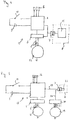
- Figure 1 shows a two-wheeler vehicle 1 according to an embodiment of the application.
- the vehicle 1 comprises an electrical auxiliary drive with a drive unit 13 being mounted on a frame 2.
- the drive unit 13 comprises an electrical motor, not shown in figure 1 , being integrated in the frame 2 in the area of the bottom bracket 17.
- the electrical motor comprises two operational modes.
- the drive unit 13 further comprises an accumulator 18 for supplying power to the electrical motor 12.
- a first operational mode of the electrical motor the vehicle 1 is operating as a pedelec and the electrical motor provides support depending on the pedalling power provided by the rider.
- the nominal continuous power of the electrical motors is unlimited at a speed between 0 and 6 km/h and equals 250 W at a speed between 6 und 25 km/h. At speeds exceeding 25 km/h, the electrical motor does not support the rider.
- vehicle 1 In its second operational mode, vehicle 1 is operated as an e-bike with a nominal continuous power of the electrical motor of 4 kW.
- the drive unit 13 can only be used in the second operational mode if the second operational mode is explicitly activated.
- the vehicle 1 comprises a vehicle registration plate 14 with an interface 7 to the vehicle 1, whereby the interface 7 comprises an electrical plug connection.
- the vehicle registration plate 14 comprises a written information in form of the registration number of the vehicle.
- the vehicle registration plate 14 can be removed from or attached to the vehicle 1.
- the vehicle registration plate 14 When the vehicle registration plate 14 is mechanically attached to the vehicle 1, the electrical connection at the interface 7 is provided at the same time.
- the vehicle registration plate 14 comprises a key unit that interacts with a power electronic circuitry of the electrical motor and activates the second operational mode.
- the second operational mode is only activated if the key unit and consequently the vehicle registration plate 14 are connected with the vehicle 1.
- FIG. 2 schematically shows a circuit diagram of a drive unit 13 according to a first embodiment.
- the drive unit 13 comprises an electrical motor 12, a power supply 3, which in this embodiment is provided as an accumulator, and an on-off-switch 10.
- a motor control device 4 and a power electronic circuitry 5 are connected via conductors 6 with motor windings of the electrical motors 12.
- the motor control device 4 receives measurement values from a plurality of sensors 16, especially the vehicle speed, the number of pedal revolutions, the pushing force at the pedals as well as the current and the voltage of the control of the electrical motor 12.
- the key unit 8 is mounted on the drive unit 13 via the interface 7.
- the key unit 8 which is indicated by the dotted line.
- the key unit 8 comprises an EEPROM 9 with an integrated vehicle chassis number for unambiguously assigning the vehicle registration plate 14 with the vehicle 1.
- the EEPROM 9 is readable by the motor control device 4.
- the power electronic circuitry 5 is works in a stand-alone-mode, that means without the key unit, only according to the official pedelec rules, that means in the first operational mode of the electromotor 12.
- the second operational mode has to be activated by the control device 4.
- the drive unit 13 works as follows.
- the drive unit 13 is supplied with energy by operating the on-off-switch 10 at the start of the vehicle 1.
- the motor control device 4 checks if the key unit 8 and accordingly if the vehicle registration plate is connected to the vehicle reading the EEPROM 9. If this is not done successfully, for example when the vehicle registration plate 14 is removed, the electrical motor 12 is only operable in the first operational mode.
- the vehicle 1 is then operated as a pedelec, whereby the motor control device 4 controls the power of the electrical motor 12 depending on the power which is provided by the pushing of the rider.
- the motor control device 4 checks the vehicle chassis number which is stored on the EEPROM 9 by reading the EEPROM 9 and compares the number with a value that is stored in the motor control device 4. If the assignment of the vehicle registration plate to the vehicle was successful, the motor control device 4 activates the required additional power for the second operational mode in the power electronic circuitry 5, such that the vehicle is operated as a moped with a nominal continuous power of 4 kW and with maximum speeds of up to 45 km/ h.
- the motor control device 4 regularly reads the EEPROM 9 during the operation to control the presence of the vehicle registration plate. If the read out of the EEPROM 9 was not successful, the motor control device 4 cancels the activation of the second operational mode such that the vehicle is temporarily only operable as a pedelec in the firs operational mode.
- Figure 3 shows a schematic circuit diagram of a drive unit according to a second embodiment.
- the second embodiment differs from the first one by the key unit 8 comprising a control device 11.
- the power electronic circuitry 5 is designed such that it operates in a stand-alone mode according to the pedelec regulation, that means in the first operational mode of the electrical motor 12.
- the control device 11 selects the operational mode and activates the additional power which is required for the second operational mode of the power electronic circuitry 5.
- Figure 4 shows a schematic circuit diagram of a drive unit 13 according to a third embodiment.
- the third embodiment differs from the first and the second ones by the key unit 8 comprising a coding unit 15.
- the power electronic circuitry 5 provides in the stand-alone mode a vehicle according to the pedelec regulation, which means in the first operational mode of the electrical motor 12.
- the coding unit 15 receives control signals from the motor control device 4 as input signals and modifies them in a predetermined manner. Only then the additional power required for the second operational mode in the power electronic circuitry 5 is provided.
- Figure 5 shows a schematic circuit diagram of a drive unit 13 according to a fourth embodiment.
- the fourth embodiment differs from the previous one by the provision of a second electrical motor 19 that is activated in the second operational mode of the drive unit 13.
- the second electrical motor 19 is operable if the key unit 8 is electrically connected with the drive unit 13 via the interface 7.
- the key unit 8 comprises, in this embodiment, a bridge 22 that connects the conductor 23 from the motor control device 4 with a conductor 24 from the power electronic circuitry 12 of the second electrical motor 19.
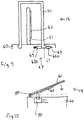
- FIG. 6 shows an embodiment of a vehicle registration plate 14.
- the vehicle registration plate 14 is mounted on a carrier 60 of a bicycle and it comprises a holding plate 61, a display plate 62, a hook 65, a hood 66 and a shutter 63.
- the display plate 62 comprises written information with a registration number and it is fixed to the holding plate 61.
- the shutter 63 is in a first, upper position, such that the display plate 62 is visible from an observer behind the vehicle.
- Figure 7 shows a cross section of the vehicle registration plate 14 along the line A-A of Figure 6 .
- the arrow F indicates the driving direction of the vehicle.
- the hood 66 has on opening to the back of the vehicle.
- the shutter 63 is fixed with its first end to the carrier 60 in the front of the holding plate 61.
- the second end of the shutter 63 comprises a electrically isolating hook 65.
- the vehicle registration plate comprises a pulley 68 running vertically above the holding plate 61.
- the shutter 63 lies on the pulley 68 such that one part of the shutter 63 is positioned behind the holding plate 61.
- Figure 7 shows the shutter 63 in the first position in which the hook 65 is above the display plate 62 such that the display plate 62 is visible.
- the carrier 60 comprises a mechanical switch 67 having two rods 670 and two springs 69.
- the two rods 670 comprise electrical connectors.
- the springs 69 in their extended state are pressing the two rods 670 together, thereby providing an electrical contact.
- a first conductor, not shown in Figure 7 from the motor control device is connected to the first rod 670 and a second conductor, not shown in Figure 7 , from the motor control device is connected to the second rod 670.
- the motor control device measures that there is an electrical connection between the first conductor and the second conductor via the two rods 670. If this is the case, the vehicle is operated as an e-bike in the second operational mode.
- Figure 8 shows the vehicle registration plate 14 of Figures 6 an 7 in a second position.
- the shutter 63 is stretched such that the hook 65 is locked in the switch 67, thereby separating the two rods 670 and compressing the springs 69.
- the hook 65 is electrically isolating, there is no electrical connection between the first conductor and the second conductor. This is detected by the motor control device and the vehicle is operated in the first operational mode as a pedelec.
- the vehicle operates in the second operational mode. If the display plate 62 is not visible as in Figure 8 , the vehicle operates in the first operational mode.
- Figure 9 shows a further embodiment of a vehicle registration plate 14, which comprises a box 90, a holding plate 61 and a display plate 62.
- the carrier 60 comprises a switch 67 similar to the previous embodiment.
- Figure 9 shows the box 90 being mounted on a carrier 60 of the vehicle by fixing an electrically isolating hook 65 of the box 90 to the switch 67.
- the box 90 covers the holding plate 61 and the display plate 62 such that the display plate 62 it not visible by an observer.
- the hook 65 is electrically isolating, the electrical connection between the two rods 670 is interrupted.
- the rods 670 are pressed together by the spring 69.
- the detection of the operational modes is done similar to the embodiment of Figures 6 to 8 . Accordingly, if the display plate 62 is visible as in Figure 9 , the vehicle operates in the second operational mode. If the display plate 62 is not visible, the vehicle operates in the first operational mode.
- FIG 10 shows a further embodiment of a vehicle registration plate 14.
- the vehicle registration plate 14 comprises a holding plate 61 and a display plate 62.
- the carrier 60 comprises an on-off-switch 101.
- the display plate 62 is fixed to the holding plate 61 and the holding plate 61 is pivot-mounted on a shaft 100 which is located at the carrier 60.
- the holding plate 61 may be put in a vertical position in which the display plate 62 is visible. In this position, the on-off-switch is on. If the holding plate 61 is hinged down to a horizontal position, the on-off-switch 101 is switched off.
- FIG 11 shows a further embodiment of a vehicle registration plate 14.
- the vehicle registration plate 14 comprises a holding plate 61 and a display plate 62.
- the display plate 62 is fixed to the holding plate 61 and the holding plate 61 is pivot-mounted on a shaft 100, which is located at the middle of the holding plate 61.
- the holding plate 61 may be put in a vertical position in which the display plate 62 is visible. In this position, the on-off-switch 101 is on. If the holding plate is turned to a horizontal position, the on-off-switch 101 is switched off.
- FIG 12 shows a further embodiment of a vehicle registration plate 14 in a top view.
- the vehicle registration plate 14 is pivot-mounted at a vertical shaft 120.
- a box 100 comprising the vehicle registration plate 14 has front and sideward ceilings such that the vehicle registration plate 14 is only visible from the back of the vehicle.
- the vehicle registration plate 14 has a form of a triangle. On each side of the triangle, there is provided one display plate 62. Only the display plate 62 which is turned to the back is visible from an observer outside the vehicle 1.
- the vehicle registration plate 14 can be turned around the shaft 120 to display further display plates 62.
- the display plates 62 differ from each other by its written information. Each of one the three display plates 62 provides a different maximum speed for the vehicle 1. Turning the vehicle registration plate 14 activates switches, not shown, which in turn activate one of three operational modes. The operational modes limit the speed of the vehicle to the currently displayed maximum speed.
- the embodiments can also be described with the following lists of elements being organized into items. The respective combinations of features which are disclosed in the item list are regarded as independent subject matter, respectively, that can also be combined with other features of the application.
Landscapes
- Engineering & Computer Science (AREA)
- Chemical & Material Sciences (AREA)
- Combustion & Propulsion (AREA)
- Mechanical Engineering (AREA)
- Transportation (AREA)
- Life Sciences & Earth Sciences (AREA)
- Sustainable Development (AREA)
- Sustainable Energy (AREA)
- Power Engineering (AREA)
- Electric Propulsion And Braking For Vehicles (AREA)
Abstract
Description
- The application relates to a vehicle with a drive train having an electrical motor, e.g. a bicycle with an electrical drive or with an electrical auxiliary drive. It also relates to a vehicle registration plate for such a vehicle as well as to a method for operating such a vehicle.
- The
DE 20 2005 006 684 U1 shows an electrical vehicle with an auxiliary motor which supports a rider of the vehicle. The support by the motor is limited to a maximum speed of the vehicle and to the acceleration phase when starting to ride the vehicle. To comply with statutory provisions, the maximum speed for a support by the auxiliary motor is currently 25 km/h in many countries. - The application provides a vehicle with a broad intended use and a high flexibility for the user. The application further provides a vehicle registration plate for such a vehicle as well as a method for operating such a vehicle.
- A vehicle comprises a drive with an electrical motor, whereby the drive comprises at least two operational modes. An operation parameter of the drive is limited to a first target area in a first operational mode and to a second target area in the second operational mode. The drive is only operable in the second operational mode if written information of a tag at or on the vehicle is visible. The drive is operable in the first operational mode, if written information of the tag is invisible.
- In one embodiment, the tag comprises a vehicle registration plate; in another embodiment, the tag comprises a written information which represents a maximum allowed speed of the vehicle.
- The switching between different operational modes of the vehicle may easily be done without the help of tools, thereby excluding misuse or at least sufficiently impeding misuse. Switching from an operational mode, in which the vehicle does not need a tag to be visible, to an operational mode, in which the tag or the written information on the tag is visible, is done by installing the tag, which in turn activates the operational mode. On the other side, the operational mode cannot be operated without installing the tag or at least without written information on the tag being visible. Switching from a vehicle with an obligation for a certificate to a vehicle without such an obligation is made easy. Thus, the vehicle provides a high flexibility for the user and it is made sure that it complies with the statutory provisions.
- Electrical bicycles, so called e-bikes, get more and more popular. The motor of e-bikes is controlled independently of the pedalling power provided by a user. The power of the motor is controlled by a manual control element, for example a turning handle comparable to that of a moped. In Germany, e-bikes have stricter statutory provisions than pedelecs. E-bikes have a maximum speed of 45 km/h, have to comprise a vehicle registration plate and require an inspection document for a motor-assisted bicycle. The application provides an e-bike that can be converted into an electrical bicycle, for which no certificate is obligatory.
- Pedelec and e-bikes each are convenient only for specific intended use. A pedelec can be used as a bicycle in a forestall or in a pedestrian area, whereas an e-bike provides a faster transportation on streets due to its higher speed and, accordingly, provides more driving pleasure.
- A vehicle providing enhanced flexibility unifies characteristics of a pedelec and of an e-bike in one single vehicle. On one hand, it can support the rider with an auxiliary motor in areas in which the use of an e-bike or a moped is not allowed. On the other hand, it provides, after switching, a fast transportation means, even if a user does not pedal. Ideally, the vehicle should provide a pedelec function as well as an e-bike function. The operation of a vehicle as e-bike requires the provision of a tag such as a vehicle registration plate. Technical means provide that the vehicle is not accidentally or improperly used without a vehicle registration plate.
- In an embodiment, the vehicle registration plate comprises a key unit that interacts with a motor control device of the vehicle to activate the second operational mode.
- In a further embodiment, a key is integrated in a vehicle registration plate to activate an e-bike operational mode that may be the second operational mode. Thus, it is ensured that the vehicle comprises a vehicle registration plate according to the official regulations if it is used as an e-bike. Preferably, for activating the second operational mode, the vehicle registration plate is provided such that an electrical connection is provided at the same time when the vehicle registration plate is installed according to the official regulations.
- In an embodiment, the key unit comprises a chip, such as an EEPROM (erasable programmable read-only memory) or another non-volatile memory, being readable by a controller. The chip may carry an written information for identifying the vehicle, such as the number of the chassis frame or a serial number, to ensure a secure assignment of the vehicle registration plate to the vehicle.
- The key unit may further comprise an additional control device that activates the second operational mode. In this embodiment, the additional control unit triggers the second operational mode during and after installing the vehicle registration plate and it activates the power electronic circuitry of the electrical motor to provide additional power.
- In a further embodiment, the key unit comprises a coding unit. The coding unit modifies control signals of the motor control device. The power electronic circuitry of the electrical motor may activate the additional power only by this code. The modification may be a simple amplification of the control signals.
- The key unit may comprise a bridge that provides an electrical contact between a conductor to the motor control device and a conductor to the power electronic circuitry of an electrical motor. Such a key unit is especially convenient if the drive comprises more than one electrical motor, whereby in the first operational mode only the first electrical motor is operational. The second electrical motor or further electrical motors are activated with the help of a key unit that triggers in the second operational mode or in further operational modes.
- In an embodiment, the nominal continuous power of the drive in a first operational mode is restricted to a first maximum value and it is restricted to the second maximum value in the second operational mode, whereby the second maximum value is larger than the first maximum value.
- In this embodiment, it is possible to operate the vehicle in a first operational mode as a pedelec with a nominal continuous power of 250 W at speeds of up to 25 km/h and in the second operational mode with a nominal continuous power of 4 kW.
- Alternatively or additionally, a second operation parameter of the vehicle may be limited, for example the vehicle speed. In an embodiment, the speed of the vehicle in the first operational mode is limited to a first maximum value and in the second operational mode to a second maximum value, whereby the second maximum value is larger than the first maximum value.
- According to an embodiment, the drive comprises at least two electrical motors, of which the first one is operable in the first operational mode, whereby in the second operational mode the second electrical motor is operable stand-alone or both the first and the second electrical motors are operable.
- The drive may comprise more than two operational modes, whereby the operation in more than one operational mode may depend on the presence of the vehicle registration plate or further keys.
- The vehicle may comprise an operating device like a pedal for driving the vehicle by a user. The vehicle may be two-wheeler, a three-wheeler or a four-wheeler.
- According to a further aspect, a vehicle registration plate comprises a key unit and a contact for an electrical connection to the vehicle. A drive unit of the vehicle comprises at least two different operational modes. An operation parameter of the drive is limited to a first target area in a first operational mode and to a second target area in a second operational mode, whereby the drive is only operable in the second operational mode, if the key unit is connected to the vehicle.
- A possibly required power supply of the vehicle registration plate may be provided by an electrical connection to the vehicle as well as by a storage like an accumulator being integrated into the vehicle registration plate.
- The key unit of the registration plate may especially comprise an electronic key unit that interacts with a motor control device of the vehicle to activate an operational mode for the drive of the vehicle.
- In an embodiment, the key unit comprises a chip, such as an EEPROM or another non-volatile memory, being readable by a motor control device of the vehicle.
- In a further embodiment, the key unit comprises an additional control device that activates an operational mode of an electrical motor of the vehicle.
- In a further embodiment the key unit comprises a coding unit.
- In a further embodiment, the key unit comprises a bridge that provides an electrical connection between a connector from a motor control device of the vehicle and a connector to the power electronic circuitry of the electrical motor of the vehicle.
- According to a further aspect, a method is provided for operating a vehicle with a drive comprising at least one electrical motor, whereby the drive comprises at least two different operational modes. An operation parameter of the drive is limited to a first target area in a first operational mode and to a second target area in a second operational mode. The second operational mode is only activated, that means that the vehicle can operate in the second operational mode, if a written information on a tag of the vehicle is visible. The drive is operable in the first operational mode, if written information of the tag is invisible.
- In one embodiment, the tag comprises a vehicle registration plate; in another embodiment, the tag comprises written information for a maximum allowed speed of the vehicle.
- In a further embodiment, the vehicle can operate only in the second operational mode if the vehicle registration plate is connected to the vehicle.
- According to an embodiment, the motor control device of the vehicle reads data from a chip, for example an EEPROM or another non-volatile memory, which is integrated in the key unit of the vehicle registration plate for checking if the vehicle registration plate is connected to the vehicle.
- According to a further embodiment, a further control device, being integrated in a key unit of the vehicle registration plate activates the second operational mode.
- According to a further embodiment, a coding unit being integrated in a key unit of the vehicle registration plate modifies control signals from a motor control device of the vehicle and the accordingly modified control signals activate the second operational mode.
- According to a further embodiment, a bridge being integrated in a key unit of the vehicle registration plate provides an electrical contact between a conductor from a motor control device of the vehicle and a conductor to the power electronic circuitry of the electrical motor of the vehicle and thereby it activates the second operational mode.
- The drive may comprise at least two electrical motors of which only the first one is operable in the first operational mode, whereby in the second operational mode, the second electrical motor is operated stand-alone or both the first and the second electrical motors are operated concurrently.
- Embodiments of the invention will be explained with reference to the attached figures.
-
Figure 1 shows a schematic view of a vehicle according to an embodiment; -
Figure 2 shows a schematic circuit diagram of a drive unit according to the first embodiment; -
Figure 3 shows a schematic circuit diagram of a drive unit according to a second embodiment; -
Figure 4 shows a schematic circuit diagram of a drive unit according to a third embodiment; -
Figure 5 shows a schematic circuit diagram of a drive unit according to fourth embodiment; -
Figure 6 shows an embodiment of a vehicle registration plate; -
Figure 7 shows a cross section of the vehicle registration plate ofFigure 6 in a first operational mode; -
Figure 8 shows a cross section of the vehicle registration plate ofFigure 6 in a second operational mode; -
Figure 9 shows a further embodiment of a vehicle registration plate; -
Figure 10 shows a further embodiment of a vehicle registration plate; -
Figure 11 shows a further embodiment of a vehicle registration plate; and -
Figure 12 shows a further embodiment of a vehicle registration plate. - Parts with same or similar functions in the figures are provided with the same reference numbers.
-
Figure 1 shows a two-wheeler vehicle 1 according to an embodiment of the application. - The
vehicle 1 comprises an electrical auxiliary drive with adrive unit 13 being mounted on a frame 2. - The
drive unit 13 comprises an electrical motor, not shown infigure 1 , being integrated in the frame 2 in the area of the bottom bracket 17. The electrical motor comprises two operational modes. Thedrive unit 13 further comprises anaccumulator 18 for supplying power to theelectrical motor 12. - In a first operational mode of the electrical motor, the
vehicle 1 is operating as a pedelec and the electrical motor provides support depending on the pedalling power provided by the rider. In this first operational mode, the nominal continuous power of the electrical motors is unlimited at a speed between 0 and 6 km/h and equals 250 W at a speed between 6 und 25 km/h. At speeds exceeding 25 km/h, the electrical motor does not support the rider. - In its second operational mode,
vehicle 1 is operated as an e-bike with a nominal continuous power of the electrical motor of 4 kW. - The
drive unit 13 can only be used in the second operational mode if the second operational mode is explicitly activated. For that purpose, thevehicle 1 comprises avehicle registration plate 14 with an interface 7 to thevehicle 1, whereby the interface 7 comprises an electrical plug connection. Thevehicle registration plate 14 comprises a written information in form of the registration number of the vehicle. Thevehicle registration plate 14 can be removed from or attached to thevehicle 1. - When the
vehicle registration plate 14 is mechanically attached to thevehicle 1, the electrical connection at the interface 7 is provided at the same time. Thevehicle registration plate 14 comprises a key unit that interacts with a power electronic circuitry of the electrical motor and activates the second operational mode. Thus, the second operational mode is only activated if the key unit and consequently thevehicle registration plate 14 are connected with thevehicle 1. -
Figure 2 schematically shows a circuit diagram of adrive unit 13 according to a first embodiment. Thedrive unit 13 comprises anelectrical motor 12, apower supply 3, which in this embodiment is provided as an accumulator, and an on-off-switch 10. Amotor control device 4 and a powerelectronic circuitry 5 are connected via conductors 6 with motor windings of theelectrical motors 12. - The
motor control device 4 receives measurement values from a plurality ofsensors 16, especially the vehicle speed, the number of pedal revolutions, the pushing force at the pedals as well as the current and the voltage of the control of theelectrical motor 12. - The
key unit 8 is mounted on thedrive unit 13 via the interface 7. Thekey unit 8 which is indicated by the dotted line. - In a first embodiment, the
key unit 8 comprises an EEPROM 9 with an integrated vehicle chassis number for unambiguously assigning thevehicle registration plate 14 with thevehicle 1. The EEPROM 9 is readable by themotor control device 4. - The power
electronic circuitry 5 is works in a stand-alone-mode, that means without the key unit, only according to the official pedelec rules, that means in the first operational mode of theelectromotor 12. The second operational mode has to be activated by thecontrol device 4. - During operation, the
drive unit 13 works as follows. Thedrive unit 13 is supplied with energy by operating the on-off-switch 10 at the start of thevehicle 1. Themotor control device 4 checks if thekey unit 8 and accordingly if the vehicle registration plate is connected to the vehicle reading the EEPROM 9. If this is not done successfully, for example when thevehicle registration plate 14 is removed, theelectrical motor 12 is only operable in the first operational mode. Thevehicle 1 is then operated as a pedelec, whereby themotor control device 4 controls the power of theelectrical motor 12 depending on the power which is provided by the pushing of the rider. - If a
vehicle registration plate 14 is mounted on thevehicle 1 and electrically connected with thevehicle 1 via the interface 7, themotor control device 4 checks the vehicle chassis number which is stored on the EEPROM 9 by reading the EEPROM 9 and compares the number with a value that is stored in themotor control device 4. If the assignment of the vehicle registration plate to the vehicle was successful, themotor control device 4 activates the required additional power for the second operational mode in the powerelectronic circuitry 5, such that the vehicle is operated as a moped with a nominal continuous power of 4 kW and with maximum speeds of up to 45 km/ h. - The
motor control device 4 regularly reads the EEPROM 9 during the operation to control the presence of the vehicle registration plate. If the read out of the EEPROM 9 was not successful, themotor control device 4 cancels the activation of the second operational mode such that the vehicle is temporarily only operable as a pedelec in the firs operational mode. -
Figure 3 shows a schematic circuit diagram of a drive unit according to a second embodiment. The second embodiment differs from the first one by thekey unit 8 comprising acontrol device 11. - The power
electronic circuitry 5 is designed such that it operates in a stand-alone mode according to the pedelec regulation, that means in the first operational mode of theelectrical motor 12. - If the
key unit 8 is electrically connected with thedrive unit 13 via the interface 7, thecontrol device 11 selects the operational mode and activates the additional power which is required for the second operational mode of the powerelectronic circuitry 5. -
Figure 4 shows a schematic circuit diagram of adrive unit 13 according to a third embodiment. The third embodiment differs from the first and the second ones by thekey unit 8 comprising acoding unit 15. In the third embodiment, the powerelectronic circuitry 5 provides in the stand-alone mode a vehicle according to the pedelec regulation, which means in the first operational mode of theelectrical motor 12. - If the
key unit 8 is connected to thedrive unit 13 via the interface 7, thecoding unit 15 receives control signals from themotor control device 4 as input signals and modifies them in a predetermined manner. Only then the additional power required for the second operational mode in the powerelectronic circuitry 5 is provided. -
Figure 5 shows a schematic circuit diagram of adrive unit 13 according to a fourth embodiment. The fourth embodiment differs from the previous one by the provision of a secondelectrical motor 19 that is activated in the second operational mode of thedrive unit 13. - The second
electrical motor 19 is operable if thekey unit 8 is electrically connected with thedrive unit 13 via the interface 7. Thekey unit 8 comprises, in this embodiment, abridge 22 that connects theconductor 23 from themotor control device 4 with aconductor 24 from the powerelectronic circuitry 12 of the secondelectrical motor 19. -
Figure 6 shows an embodiment of avehicle registration plate 14. Thevehicle registration plate 14 is mounted on acarrier 60 of a bicycle and it comprises a holdingplate 61, adisplay plate 62, ahook 65, ahood 66 and ashutter 63. Thedisplay plate 62 comprises written information with a registration number and it is fixed to the holdingplate 61. Theshutter 63 is in a first, upper position, such that thedisplay plate 62 is visible from an observer behind the vehicle. -
Figure 7 shows a cross section of thevehicle registration plate 14 along the line A-A ofFigure 6 . The arrow F indicates the driving direction of the vehicle. Thehood 66 has on opening to the back of the vehicle. Theshutter 63 is fixed with its first end to thecarrier 60 in the front of the holdingplate 61. The second end of theshutter 63 comprises a electrically isolatinghook 65. The vehicle registration plate comprises apulley 68 running vertically above the holdingplate 61. Theshutter 63 lies on thepulley 68 such that one part of theshutter 63 is positioned behind the holdingplate 61.Figure 7 shows theshutter 63 in the first position in which thehook 65 is above thedisplay plate 62 such that thedisplay plate 62 is visible. - The
carrier 60 comprises amechanical switch 67 having tworods 670 and twosprings 69. The tworods 670 comprise electrical connectors. Thesprings 69 in their extended state are pressing the tworods 670 together, thereby providing an electrical contact. A first conductor, not shown inFigure 7 , from the motor control device is connected to thefirst rod 670 and a second conductor, not shown inFigure 7 , from the motor control device is connected to thesecond rod 670. - The motor control device measures that there is an electrical connection between the first conductor and the second conductor via the two
rods 670. If this is the case, the vehicle is operated as an e-bike in the second operational mode. -
Figure 8 shows thevehicle registration plate 14 ofFigures 6 an 7 in a second position. In the second position, theshutter 63 is stretched such that thehook 65 is locked in theswitch 67, thereby separating the tworods 670 and compressing thesprings 69. As thehook 65 is electrically isolating, there is no electrical connection between the first conductor and the second conductor. This is detected by the motor control device and the vehicle is operated in the first operational mode as a pedelec. - Accordingly, if the
display plate 62 is visible as inFigures 6 and 7 , the vehicle operates in the second operational mode. If thedisplay plate 62 is not visible as inFigure 8 , the vehicle operates in the first operational mode. -
Figure 9 shows a further embodiment of avehicle registration plate 14, which comprises abox 90, a holdingplate 61 and adisplay plate 62. Thecarrier 60 comprises aswitch 67 similar to the previous embodiment.Figure 9 shows thebox 90 being mounted on acarrier 60 of the vehicle by fixing an electrically isolatinghook 65 of thebox 90 to theswitch 67. Thebox 90 covers the holdingplate 61 and thedisplay plate 62 such that thedisplay plate 62 it not visible by an observer. As thehook 65 is electrically isolating, the electrical connection between the tworods 670 is interrupted. - If the
box 90 with itshook 65 is removed, not shown inFigure 9 , therods 670 are pressed together by thespring 69. The detection of the operational modes is done similar to the embodiment ofFigures 6 to 8 . Accordingly, if thedisplay plate 62 is visible as inFigure 9 , the vehicle operates in the second operational mode. If thedisplay plate 62 is not visible, the vehicle operates in the first operational mode. -
Figure 10 shows a further embodiment of avehicle registration plate 14. Thevehicle registration plate 14 comprises a holdingplate 61 and adisplay plate 62. Thecarrier 60 comprises an on-off-switch 101. Thedisplay plate 62 is fixed to the holdingplate 61 and the holdingplate 61 is pivot-mounted on ashaft 100 which is located at thecarrier 60. The holdingplate 61 may be put in a vertical position in which thedisplay plate 62 is visible. In this position, the on-off-switch is on. If the holdingplate 61 is hinged down to a horizontal position, the on-off-switch 101 is switched off. -
Figure 11 shows a further embodiment of avehicle registration plate 14. Thevehicle registration plate 14 comprises a holdingplate 61 and adisplay plate 62. Thedisplay plate 62 is fixed to the holdingplate 61 and the holdingplate 61 is pivot-mounted on ashaft 100, which is located at the middle of the holdingplate 61. The holdingplate 61 may be put in a vertical position in which thedisplay plate 62 is visible. In this position, the on-off-switch 101 is on. If the holding plate is turned to a horizontal position, the on-off-switch 101 is switched off. -
Figure 12 shows a further embodiment of avehicle registration plate 14 in a top view. Thevehicle registration plate 14 is pivot-mounted at avertical shaft 120. Abox 100 comprising thevehicle registration plate 14 has front and sideward ceilings such that thevehicle registration plate 14 is only visible from the back of the vehicle. Thevehicle registration plate 14 has a form of a triangle. On each side of the triangle, there is provided onedisplay plate 62. Only thedisplay plate 62 which is turned to the back is visible from an observer outside thevehicle 1. Thevehicle registration plate 14 can be turned around theshaft 120 to displayfurther display plates 62. - The
display plates 62 differ from each other by its written information. Each of one the threedisplay plates 62 provides a different maximum speed for thevehicle 1. Turning thevehicle registration plate 14 activates switches, not shown, which in turn activate one of three operational modes. The operational modes limit the speed of the vehicle to the currently displayed maximum speed.
The embodiments can also be described with the following lists of elements being organized into items. The respective combinations of features which are disclosed in the item list are regarded as independent subject matter, respectively, that can also be combined with other features of the application. - 1. Vehicle with a drive having at least one electrical motor, whereby the drive comprises at least two different operational modes and whereby an operation parameter of the drive is limited to a first target area in a first operational mode and to a second target area in a second operational mode, whereby the drive is operable in the second operational mode, if a written information of a tag of the vehicle is visible, and the drive is operable in the first operational mode, if the written information of the tag is invisible.
- 2. Vehicle according to
item 1,
whereby the tag comprises a vehicle registration plate. - 3. Vehicle according to one of the
items 1 to 2,
whereby the tag is visible if the tag is connected to the vehicle and is invisible if the tag is removed from the vehicle. - 4. Vehicle according to one of the
items 1 to 3, whereby the tag comprises a key unit that interacts with a motor control device of the vehicle to activate the second operational mode for the drive. - 5. Vehicle according to
item 4, whereby the key unit comprises a chip being readable by the motor control device. - 6. Vehicle according to
item 4, whereby the key unit
comprises a further control device for activating the second operational mode of the drive. - 7. Vehicle according to
item 4, whereby the key unit comprises a coding unit. - 8. Vehicle according to
item 4, whereby the key unit comprises a bridge for providing an electrical contact between a conductor from the motor control device and a conductor to the power electronic circuitry of an electrical motor. - 9. Vehicle according to one of the
items 1 to 8, whereby the nominal continuous power of the drive is restricted to a first maximum value in the first operational mode and is restricted to a second maximum value in the second operational mode, whereby the second maximal value is larger than the first maximum value. - 10. Vehicle according to one of the
items 1 to 8, whereby the speed of the vehicle is restricted to a first maximum value in the first operational mode and is restricted to a second maximum value in the second operational mode, whereby the second maximum value is larger than the first maximum value. - 11. Vehicle according to one of the
items 1 to 10, whereby the drive comprises at least two electrical motors, of which only the first electrical motor is operable in the first operational mode, whereby in the second operational mode the second electrical motor is operable in stand-alone mode or both the first electrical motor and the second electrical motor are operable. - 12. Vehicle according to one of the
items 1 to 11, whereby the drive comprises more than two operational modes. - 13. Vehicle according to one of the
items 1 to 12, whereby the vehicle comprises an operating device for driving the vehicle by a user. - 14. Vehicle according to one of the
items 1 to 13, whereby the vehicle is constructed as a two-wheeler. - 15. Vehicle according to one of the
items 1 to 13, whereby the vehicle is constructed as a three-wheeler. - 16. Vehicle registration plate with a key unit and a contact for an electrical connection to a vehicle, the vehicle comprising a drive with at least one electrical motor, whereby the drive comprises at least two different operational modes and whereby an operation parameter of the drive is limited to a first target area in a first operational mode and to a second target area in a second operational mode, whereby the drive is only operable in the second operational mode, if the key unit is connected to the vehicle.
- 17. Vehicle registration plate according to
item 16, whereby the key unit is constructed as electronic key unit that interacts with a motor control device of the vehicle to activate an operational mode of the drive of the vehicle. - 18. Vehicle registration plate according to item 17, whereby the key unit comprises a chip being readable by a motor control device of a vehicle.
- 19. Vehicle registration plate according to item 17, whereby the key unit comprises a further control device activating an operational mode of an electrical motor of the vehicle.
- 20. Vehicle registration plate according to item 17, whereby the key unit comprises a coding unit.
- 21. Vehicle registration plate according to
item 16 or 17, whereby the key unit comprises a bridge that provides an electrical contact between a conductor from a motor control device of the vehicle and a conductor to a power electronic circuitry of the electrical motor of the vehicle. - 22. Method for operating a vehicle with a drive having at least one electrical motor, whereby the drive comprises at least two operational modes and an operation parameter of the drive is limited to a first target area in a first operational mode and to a second target area in a second operational mode, whereby the second operational mode is activated, if a written information of a tag of the vehicle is visible, and the drive is operable in the first operational mode, if the written information of the tag is invisible.
- 23. Method according to
item 22,
whereby the tag comprises a vehicle registration plate. - 24. Method according to one of the
items 22 to 23,
whereby the tag is visible if the tag is connected to the vehicle and is invisible of the tag is removed from the vehicle. - 25. Method according to
item 22, whereby a motor control device of the vehicle is adapted to read out a chip being integrated in a key unit in the vehicle registration plate for checking if the vehicle registration plate is connected to the vehicle. - 26. Method according to
item 24, whereby a further control device being integrated in a key unit in the vehicle registration plate activates the second operational mode. - 27. Method according to item 26, whereby a coding unit being integrated in the key unit in the vehicle registration plate modifies control signals form a motor control device of the vehicle and the accordingly modified control signals activate the second operational mode.
- 28. Method according to
item 24, whereby a bridge integrated in a key unit in the vehicle registration plate provides an electrical contact between a conductor from a motor control device of the vehicle and a conductor to a power electronic circuitry (20) of an electrical motor of the vehicle, thereby activating the second operational mode. - 29. Method according to one of the
items 24 to 28, whereby the drive comprises at least two electrical motors, of which only the first electrical motor is operable in the first operational mode, whereby in the second operational mode the second electrical motor is operated stand-alone or both the first electrical motor and the second electrical motor are operated.
Claims (15)
- Vehicle (1) with a drive having at least one electrical motor (12), whereby the drive comprises at least two different operational modes and whereby an operation parameter of the drive is limited to a first target area in a first operational mode and to a second target area in a second operational mode, the vehicle (1) comprising a vehicle registration plate (14), the vehicle registration plate (14) comprising a holding plate (61), a display plate (62), a carrier (60), the carrier (60) comprising a switch (10, 67), and a movable cover (63, 90), wherein the switch (10, 67) is turned on or off by engaging or disengaging the movable cover (63, 90) with the carrier (60), whereby the drive is operable in the second operational mode, if the switch (10, 67) is turned on, and the drive is operable in the first operational mode, if the switch (10, 67) is turned off.
- Vehicle (1) according to claim 1, wherein the movable cover (63, 90) is selected from a shutter (63) and a box (90).
- Vehicle (1) according to claim 1 or claim 2, wherein the movable cover (63, 90) is a shutter (63), one end of the shutter (63) comprising an electrically isolating hook (65), the hook (65) being provided for engagement with the switch (10, 67).
- Vehicle (1) according to claim 1 or claim 2, wherein the movable cover (63, 90) is a box (90), one end of the box (90) comprising an electrically isolating hook (65), the hook (65) being provided for engagement with the switch (10, 67).
- Vehicle (1) according to one of the claims 1 to 4, whereby the vehicle registration plate (14) comprises a key unit (8) that interacts with a motor control device (4) of the vehicle (1) to activate the second operational mode for the drive.
- Vehicle (1) according to claim 5, whereby the key unit (8) comprises a chip being readable by the motor control device (4).
- Vehicle (1) according to claim 5, whereby the key unit (8) comprises a coding unit (15).
- Vehicle (1) according to claim 5, whereby the key unit (8) comprises a bridge (22) for providing an electrical contact between a conductor from the motor control device (4) and a conductor to the power electronic circuitry of an electrical motor (12).
- Vehicle (1) according to one of the claims 1 to 8, whereby the nominal continuous power of the drive is restricted to a first maximum value in the first operational mode and is restricted to a second maximum value in the second operational mode, whereby the second maximal value is larger than the first maximum value.
- Vehicle (1) according to one of the claims 1 to 8, whereby the speed of the vehicle (1) is restricted to a first maximum value in the first operational mode and is restricted to a second maximum value in the second operational mode, whereby the second maximum value is larger than the first maximum value.
- Vehicle registration plate (14), the vehicle registration plate (14) comprising a holding plate (61), a display plate (62), a carrier (60), the carrier (60) comprising a switch (10, 67), and a movable cover (63, 90), and a contact for an electrical connection to a vehicle (1), the vehicle (1) comprising a drive with at least one electrical motor, wherein the switch (10, 67) is turned on or off by engaging or disengaging the movable cover (63, 90) with the carrier (60),
whereby the drive comprises at least two different operational modes and whereby an operation parameter of the drive is limited to a first target area in a first operational mode and to a second target area in a second operational mode, whereby the drive is operable in the second operational mode if the switch (10, 67) is turned on, and the drive is operable in the first operational mode, if the switch (10, 67) is turned off. - Vehicle registration plate (14) according to claim 11, wherein the movable cover (63, 90) is selected from a shutter (63) and a box (90)
- Vehicle registration plate according to claim 11 or claim 12, wherein the movable cover (63, 90) is a shutter (63), one end of the shutter (63) comprising an electrically isolating hook (65), the hook (65) being provided for engagement with the switch (10, 67).
- Vehicle according to claim 11 or claim 12, wherein the movable cover (63, 90) is a box (90), one end of the box (90) comprising an electrically isolating hook (65), the hook (65) being provided for engagement with the switch (10, 67).
- Vehicle registration plate (14) according to one of the claims 11 to 14, comprising a key unit (8), whereby the key unit (8) is constructed as electronic key unit (8) that interacts with a motor control device of the vehicle (1) to activate an operational mode of the drive of the vehicle (1).
Applications Claiming Priority (4)
| Application Number | Priority Date | Filing Date | Title |
|---|---|---|---|
| DE102010016009.1A DE102010016009B4 (en) | 2010-03-18 | 2010-03-18 | Vehicle, assembly and method for operating a vehicle |
| PCT/IB2011/051149 WO2011114316A2 (en) | 2010-03-18 | 2011-03-18 | Vehicle, vehicle registration plate and method for operating a vehicle |
| EP11755781.9A EP2547579B1 (en) | 2010-03-18 | 2011-03-18 | Vehicle, vehicle registration plate and method for operating a vehicle |
| EP15167710.1A EP2949566B1 (en) | 2010-03-18 | 2011-03-18 | Vehicle and vehicle registration plate |
Related Parent Applications (3)
| Application Number | Title | Priority Date | Filing Date |
|---|---|---|---|
| EP11755781.9A Division EP2547579B1 (en) | 2010-03-18 | 2011-03-18 | Vehicle, vehicle registration plate and method for operating a vehicle |
| EP15167710.1A Division EP2949566B1 (en) | 2010-03-18 | 2011-03-18 | Vehicle and vehicle registration plate |
| EP15167710.1A Division-Into EP2949566B1 (en) | 2010-03-18 | 2011-03-18 | Vehicle and vehicle registration plate |
Related Child Applications (1)
| Application Number | Title | Priority Date | Filing Date |
|---|---|---|---|
| EP21150657.1 Division-Into | 2021-01-08 |
Publications (2)
| Publication Number | Publication Date |
|---|---|
| EP3231699A1 true EP3231699A1 (en) | 2017-10-18 |
| EP3231699B1 EP3231699B1 (en) | 2021-02-24 |
Family
ID=44585449
Family Applications (3)
| Application Number | Title | Priority Date | Filing Date |
|---|---|---|---|
| EP15167710.1A Active EP2949566B1 (en) | 2010-03-18 | 2011-03-18 | Vehicle and vehicle registration plate |
| EP11755781.9A Active EP2547579B1 (en) | 2010-03-18 | 2011-03-18 | Vehicle, vehicle registration plate and method for operating a vehicle |
| EP17167248.8A Active EP3231699B1 (en) | 2010-03-18 | 2011-03-18 | Vehicle and vehicle registration plate |
Family Applications Before (2)
| Application Number | Title | Priority Date | Filing Date |
|---|---|---|---|
| EP15167710.1A Active EP2949566B1 (en) | 2010-03-18 | 2011-03-18 | Vehicle and vehicle registration plate |
| EP11755781.9A Active EP2547579B1 (en) | 2010-03-18 | 2011-03-18 | Vehicle, vehicle registration plate and method for operating a vehicle |
Country Status (4)
| Country | Link |
|---|---|
| EP (3) | EP2949566B1 (en) |
| DE (1) | DE102010016009B4 (en) |
| DK (1) | DK2547579T3 (en) |
| WO (1) | WO2011114316A2 (en) |
Cited By (5)
| Publication number | Priority date | Publication date | Assignee | Title |
|---|---|---|---|---|
| DE102018203597A1 (en) * | 2018-03-09 | 2019-09-12 | Zf Friedrichshafen Ag | Setting a maximum speed of a vehicle depending on a qualification of a vehicle user |
| DE102018219298A1 (en) * | 2018-11-12 | 2020-05-14 | Robert Bosch Gmbh | Method for controlling an electric motor of an electric bicycle, control unit for carrying out the method and electric bicycle with the control unit, and input method and mobile computing unit for carrying out the input method |
| WO2022058157A1 (en) * | 2020-09-15 | 2022-03-24 | Bayerische Motoren Werke Aktiengesellschaft | Method for providing an adaptive mobility solution, and associated vehicle |
| JP2022189348A (en) * | 2021-06-11 | 2022-12-22 | カワサキモータース株式会社 | vehicle |
| JP2023009308A (en) * | 2021-06-28 | 2023-01-20 | カワサキモータース株式会社 | Ride and vehicle control method |
Families Citing this family (3)
| Publication number | Priority date | Publication date | Assignee | Title |
|---|---|---|---|---|
| CN108528617B (en) | 2014-12-05 | 2021-05-28 | 株式会社岛野 | bicycle control device |
| DE102019124514A1 (en) * | 2019-09-12 | 2021-03-18 | Bayerische Motoren Werke Aktiengesellschaft | Vehicle and method for operating a drive motor of a vehicle |
| CN117295655A (en) * | 2021-05-11 | 2023-12-26 | 本田技研工业株式会社 | Vehicle, notification method, notification procedure, storage medium and notification device |
Citations (3)
| Publication number | Priority date | Publication date | Assignee | Title |
|---|---|---|---|---|
| US5826675A (en) * | 1996-07-05 | 1998-10-27 | Yamaha Hatsudoki Kabushiki Kaisha | Electric motor assisted vehicle |
| DE202005006684U1 (en) | 2005-04-25 | 2005-08-25 | Sun & Cycle GmbH Innovative Fahrzeugsysteme | Electric drive mechanism for a vehicle like an electrically driven bicycle has a user's operating device for working a vehicle and an auxiliary motor influenced by a control device |
| GB2453598A (en) * | 2007-10-12 | 2009-04-15 | Gould Autoplates And Signs Ltd | A registration plate incorporating a transponder |
Family Cites Families (4)
| Publication number | Priority date | Publication date | Assignee | Title |
|---|---|---|---|---|
| DE3308803A1 (en) * | 1983-03-12 | 1984-09-13 | Hans-Hellmut Dipl.-Ing. 2061 Sülfeld Ernst | START OPERATING AND CONTROL UNIT FOR MOTOR VEHICLES |
| JP2919684B2 (en) * | 1992-10-30 | 1999-07-12 | 三洋電機株式会社 | Electric bicycle |
| US6446745B1 (en) * | 2000-06-30 | 2002-09-10 | Michael John Lee | Control system for electric powered vehicle |
| JP2004345400A (en) * | 2003-05-20 | 2004-12-09 | Sony Corp | Electric assist bicycle |
-
2010
- 2010-03-18 DE DE102010016009.1A patent/DE102010016009B4/en active Active
-
2011
- 2011-03-18 EP EP15167710.1A patent/EP2949566B1/en active Active
- 2011-03-18 WO PCT/IB2011/051149 patent/WO2011114316A2/en not_active Ceased
- 2011-03-18 EP EP11755781.9A patent/EP2547579B1/en active Active
- 2011-03-18 EP EP17167248.8A patent/EP3231699B1/en active Active
- 2011-03-18 DK DK11755781.9T patent/DK2547579T3/en active
Patent Citations (3)
| Publication number | Priority date | Publication date | Assignee | Title |
|---|---|---|---|---|
| US5826675A (en) * | 1996-07-05 | 1998-10-27 | Yamaha Hatsudoki Kabushiki Kaisha | Electric motor assisted vehicle |
| DE202005006684U1 (en) | 2005-04-25 | 2005-08-25 | Sun & Cycle GmbH Innovative Fahrzeugsysteme | Electric drive mechanism for a vehicle like an electrically driven bicycle has a user's operating device for working a vehicle and an auxiliary motor influenced by a control device |
| GB2453598A (en) * | 2007-10-12 | 2009-04-15 | Gould Autoplates And Signs Ltd | A registration plate incorporating a transponder |
Cited By (7)
| Publication number | Priority date | Publication date | Assignee | Title |
|---|---|---|---|---|
| DE102018203597A1 (en) * | 2018-03-09 | 2019-09-12 | Zf Friedrichshafen Ag | Setting a maximum speed of a vehicle depending on a qualification of a vehicle user |
| DE102018219298A1 (en) * | 2018-11-12 | 2020-05-14 | Robert Bosch Gmbh | Method for controlling an electric motor of an electric bicycle, control unit for carrying out the method and electric bicycle with the control unit, and input method and mobile computing unit for carrying out the input method |
| WO2022058157A1 (en) * | 2020-09-15 | 2022-03-24 | Bayerische Motoren Werke Aktiengesellschaft | Method for providing an adaptive mobility solution, and associated vehicle |
| CN116157300A (en) * | 2020-09-15 | 2023-05-23 | 宝马股份公司 | Method and related means of transportation for providing adaptive mobility solutions |
| US20230322322A1 (en) * | 2020-09-15 | 2023-10-12 | Bayerische Motoren Werke Aktiengesellschaft | Method For Providing an Adaptive Mobility Solution, and Associated Vehicle |
| JP2022189348A (en) * | 2021-06-11 | 2022-12-22 | カワサキモータース株式会社 | vehicle |
| JP2023009308A (en) * | 2021-06-28 | 2023-01-20 | カワサキモータース株式会社 | Ride and vehicle control method |
Also Published As
| Publication number | Publication date |
|---|---|
| DE102010016009B4 (en) | 2020-01-16 |
| EP2949566A1 (en) | 2015-12-02 |
| EP2547579A4 (en) | 2013-10-16 |
| EP3231699B1 (en) | 2021-02-24 |
| DK2547579T3 (en) | 2015-08-03 |
| EP2547579B1 (en) | 2015-06-24 |
| EP2949566B1 (en) | 2017-05-31 |
| DE102010016009A1 (en) | 2011-09-22 |
| EP2547579A2 (en) | 2013-01-23 |
| WO2011114316A2 (en) | 2011-09-22 |
| WO2011114316A3 (en) | 2011-12-22 |
Similar Documents
| Publication | Publication Date | Title |
|---|---|---|
| EP2949566B1 (en) | Vehicle and vehicle registration plate | |
| CN102730142B (en) | Motor-assisted bicycle | |
| CN115402100A (en) | Vehicle activation system and method for electric vehicle | |
| CN108430862B (en) | Remote Control Units and Electric Bikes | |
| CN102510826B (en) | For regulating the apparatus and method of regeneration in pedal-driven vehicle | |
| JP4906982B1 (en) | Electric bicycle | |
| JP6720034B2 (en) | Electric assisted bicycle | |
| JP2017065319A (en) | Straddle-type electric vehicle | |
| US7412309B2 (en) | Electric vehicle | |
| CN100398386C (en) | electric bicycle | |
| KR970706985A (en) | SAFETY MECHANISM FOR ELECTRIC VEHICLE | |
| JP2017077126A (en) | Electric propulsion machine and battery unit | |
| CN110182295B (en) | Control device and control system | |
| JP2006273142A (en) | Electric vehicle having burglary preventive function | |
| CN100343119C (en) | Electronic Control Units for Bicycles | |
| JP2010058769A (en) | Control device in electric vehicle | |
| WO2006120328A1 (en) | Automatic cycle stacking system | |
| CN104773238A (en) | Intelligent balance car | |
| KR100858555B1 (en) | Bicycle storage | |
| EP2913259B1 (en) | Management system of electrically assisted bicycle, parking station system, electrically assisted bicycle, electrically assisted bicycle provision system and method for management of an electrically assisted bicycle and parking station | |
| EP2189359A1 (en) | Bicycle control device | |
| KR101391372B1 (en) | Motorized two-wheel bike | |
| JP2013233024A (en) | Power supply system for vehicle | |
| US10597911B2 (en) | Motor vehicle locking mechanism | |
| CN205693399U (en) | A kind of charging system of compatible electric bicycle charging |
Legal Events
| Date | Code | Title | Description |
|---|---|---|---|
| PUAI | Public reference made under article 153(3) epc to a published international application that has entered the european phase |
Free format text: ORIGINAL CODE: 0009012 |
|
| STAA | Information on the status of an ep patent application or granted ep patent |
Free format text: STATUS: THE APPLICATION HAS BEEN PUBLISHED |
|
| AC | Divisional application: reference to earlier application |
Ref document number: 2547579 Country of ref document: EP Kind code of ref document: P Ref document number: 2949566 Country of ref document: EP Kind code of ref document: P |
|
| AK | Designated contracting states |
Kind code of ref document: A1 Designated state(s): AL AT BE BG CH CY CZ DE DK EE ES FI FR GB GR HR HU IE IS IT LI LT LU LV MC MK MT NL NO PL PT RO RS SE SI SK SM TR |
|
| STAA | Information on the status of an ep patent application or granted ep patent |
Free format text: STATUS: REQUEST FOR EXAMINATION WAS MADE |
|
| 17P | Request for examination filed |
Effective date: 20180417 |
|
| RBV | Designated contracting states (corrected) |
Designated state(s): AL AT BE BG CH CY CZ DE DK EE ES FI FR GB GR HR HU IE IS IT LI LT LU LV MC MK MT NL NO PL PT RO RS SE SI SK SM TR |
|
| STAA | Information on the status of an ep patent application or granted ep patent |
Free format text: STATUS: EXAMINATION IS IN PROGRESS |
|
| 17Q | First examination report despatched |
Effective date: 20200122 |
|
| GRAP | Despatch of communication of intention to grant a patent |
Free format text: ORIGINAL CODE: EPIDOSNIGR1 |
|
| STAA | Information on the status of an ep patent application or granted ep patent |
Free format text: STATUS: GRANT OF PATENT IS INTENDED |
|
| INTG | Intention to grant announced |
Effective date: 20200911 |
|
| GRAS | Grant fee paid |
Free format text: ORIGINAL CODE: EPIDOSNIGR3 |
|
| GRAA | (expected) grant |
Free format text: ORIGINAL CODE: 0009210 |
|
| STAA | Information on the status of an ep patent application or granted ep patent |
Free format text: STATUS: THE PATENT HAS BEEN GRANTED |
|
| AC | Divisional application: reference to earlier application |
Ref document number: 2547579 Country of ref document: EP Kind code of ref document: P Ref document number: 2949566 Country of ref document: EP Kind code of ref document: P |
|
| AK | Designated contracting states |
Kind code of ref document: B1 Designated state(s): AL AT BE BG CH CY CZ DE DK EE ES FI FR GB GR HR HU IE IS IT LI LT LU LV MC MK MT NL NO PL PT RO RS SE SI SK SM TR |
|
| REG | Reference to a national code |
Ref country code: CH Ref legal event code: EP |
|
| REG | Reference to a national code |
Ref country code: DE Ref legal event code: R096 Ref document number: 602011070259 Country of ref document: DE |
|
| REG | Reference to a national code |
Ref country code: AT Ref legal event code: REF Ref document number: 1364129 Country of ref document: AT Kind code of ref document: T Effective date: 20210315 |
|
| REG | Reference to a national code |
Ref country code: IE Ref legal event code: FG4D |
|
| REG | Reference to a national code |
Ref country code: LT Ref legal event code: MG9D |
|
| REG | Reference to a national code |
Ref country code: NL Ref legal event code: MP Effective date: 20210224 |
|
| PG25 | Lapsed in a contracting state [announced via postgrant information from national office to epo] |
Ref country code: FI Free format text: LAPSE BECAUSE OF FAILURE TO SUBMIT A TRANSLATION OF THE DESCRIPTION OR TO PAY THE FEE WITHIN THE PRESCRIBED TIME-LIMIT Effective date: 20210224 Ref country code: HR Free format text: LAPSE BECAUSE OF FAILURE TO SUBMIT A TRANSLATION OF THE DESCRIPTION OR TO PAY THE FEE WITHIN THE PRESCRIBED TIME-LIMIT Effective date: 20210224 Ref country code: GR Free format text: LAPSE BECAUSE OF FAILURE TO SUBMIT A TRANSLATION OF THE DESCRIPTION OR TO PAY THE FEE WITHIN THE PRESCRIBED TIME-LIMIT Effective date: 20210525 Ref country code: NO Free format text: LAPSE BECAUSE OF FAILURE TO SUBMIT A TRANSLATION OF THE DESCRIPTION OR TO PAY THE FEE WITHIN THE PRESCRIBED TIME-LIMIT Effective date: 20210524 Ref country code: PT Free format text: LAPSE BECAUSE OF FAILURE TO SUBMIT A TRANSLATION OF THE DESCRIPTION OR TO PAY THE FEE WITHIN THE PRESCRIBED TIME-LIMIT Effective date: 20210624 Ref country code: LT Free format text: LAPSE BECAUSE OF FAILURE TO SUBMIT A TRANSLATION OF THE DESCRIPTION OR TO PAY THE FEE WITHIN THE PRESCRIBED TIME-LIMIT Effective date: 20210224 Ref country code: BG Free format text: LAPSE BECAUSE OF FAILURE TO SUBMIT A TRANSLATION OF THE DESCRIPTION OR TO PAY THE FEE WITHIN THE PRESCRIBED TIME-LIMIT Effective date: 20210524 |
|
| REG | Reference to a national code |
Ref country code: AT Ref legal event code: MK05 Ref document number: 1364129 Country of ref document: AT Kind code of ref document: T Effective date: 20210224 |
|
| PG25 | Lapsed in a contracting state [announced via postgrant information from national office to epo] |
Ref country code: LV Free format text: LAPSE BECAUSE OF FAILURE TO SUBMIT A TRANSLATION OF THE DESCRIPTION OR TO PAY THE FEE WITHIN THE PRESCRIBED TIME-LIMIT Effective date: 20210224 Ref country code: PL Free format text: LAPSE BECAUSE OF FAILURE TO SUBMIT A TRANSLATION OF THE DESCRIPTION OR TO PAY THE FEE WITHIN THE PRESCRIBED TIME-LIMIT Effective date: 20210224 Ref country code: NL Free format text: LAPSE BECAUSE OF FAILURE TO SUBMIT A TRANSLATION OF THE DESCRIPTION OR TO PAY THE FEE WITHIN THE PRESCRIBED TIME-LIMIT Effective date: 20210224 Ref country code: RS Free format text: LAPSE BECAUSE OF FAILURE TO SUBMIT A TRANSLATION OF THE DESCRIPTION OR TO PAY THE FEE WITHIN THE PRESCRIBED TIME-LIMIT Effective date: 20210224 Ref country code: SE Free format text: LAPSE BECAUSE OF FAILURE TO SUBMIT A TRANSLATION OF THE DESCRIPTION OR TO PAY THE FEE WITHIN THE PRESCRIBED TIME-LIMIT Effective date: 20210224 |
|
| PG25 | Lapsed in a contracting state [announced via postgrant information from national office to epo] |
Ref country code: IS Free format text: LAPSE BECAUSE OF FAILURE TO SUBMIT A TRANSLATION OF THE DESCRIPTION OR TO PAY THE FEE WITHIN THE PRESCRIBED TIME-LIMIT Effective date: 20210624 |
|
| PG25 | Lapsed in a contracting state [announced via postgrant information from national office to epo] |
Ref country code: CZ Free format text: LAPSE BECAUSE OF FAILURE TO SUBMIT A TRANSLATION OF THE DESCRIPTION OR TO PAY THE FEE WITHIN THE PRESCRIBED TIME-LIMIT Effective date: 20210224 Ref country code: EE Free format text: LAPSE BECAUSE OF FAILURE TO SUBMIT A TRANSLATION OF THE DESCRIPTION OR TO PAY THE FEE WITHIN THE PRESCRIBED TIME-LIMIT Effective date: 20210224 Ref country code: SM Free format text: LAPSE BECAUSE OF FAILURE TO SUBMIT A TRANSLATION OF THE DESCRIPTION OR TO PAY THE FEE WITHIN THE PRESCRIBED TIME-LIMIT Effective date: 20210224 Ref country code: AT Free format text: LAPSE BECAUSE OF FAILURE TO SUBMIT A TRANSLATION OF THE DESCRIPTION OR TO PAY THE FEE WITHIN THE PRESCRIBED TIME-LIMIT Effective date: 20210224 |
|
| REG | Reference to a national code |
Ref country code: CH Ref legal event code: PL |
|
| REG | Reference to a national code |
Ref country code: DE Ref legal event code: R097 Ref document number: 602011070259 Country of ref document: DE |
|
| PG25 | Lapsed in a contracting state [announced via postgrant information from national office to epo] |
Ref country code: DK Free format text: LAPSE BECAUSE OF FAILURE TO SUBMIT A TRANSLATION OF THE DESCRIPTION OR TO PAY THE FEE WITHIN THE PRESCRIBED TIME-LIMIT Effective date: 20210224 Ref country code: MC Free format text: LAPSE BECAUSE OF FAILURE TO SUBMIT A TRANSLATION OF THE DESCRIPTION OR TO PAY THE FEE WITHIN THE PRESCRIBED TIME-LIMIT Effective date: 20210224 Ref country code: RO Free format text: LAPSE BECAUSE OF FAILURE TO SUBMIT A TRANSLATION OF THE DESCRIPTION OR TO PAY THE FEE WITHIN THE PRESCRIBED TIME-LIMIT Effective date: 20210224 Ref country code: SK Free format text: LAPSE BECAUSE OF FAILURE TO SUBMIT A TRANSLATION OF THE DESCRIPTION OR TO PAY THE FEE WITHIN THE PRESCRIBED TIME-LIMIT Effective date: 20210224 |
|
| REG | Reference to a national code |
Ref country code: BE Ref legal event code: MM Effective date: 20210331 |
|
| PLBE | No opposition filed within time limit |
Free format text: ORIGINAL CODE: 0009261 |
|
| STAA | Information on the status of an ep patent application or granted ep patent |
Free format text: STATUS: NO OPPOSITION FILED WITHIN TIME LIMIT |
|
| PG25 | Lapsed in a contracting state [announced via postgrant information from national office to epo] |
Ref country code: ES Free format text: LAPSE BECAUSE OF FAILURE TO SUBMIT A TRANSLATION OF THE DESCRIPTION OR TO PAY THE FEE WITHIN THE PRESCRIBED TIME-LIMIT Effective date: 20210224 Ref country code: IE Free format text: LAPSE BECAUSE OF NON-PAYMENT OF DUE FEES Effective date: 20210318 Ref country code: LU Free format text: LAPSE BECAUSE OF NON-PAYMENT OF DUE FEES Effective date: 20210318 Ref country code: LI Free format text: LAPSE BECAUSE OF NON-PAYMENT OF DUE FEES Effective date: 20210331 Ref country code: AL Free format text: LAPSE BECAUSE OF FAILURE TO SUBMIT A TRANSLATION OF THE DESCRIPTION OR TO PAY THE FEE WITHIN THE PRESCRIBED TIME-LIMIT Effective date: 20210224 Ref country code: CH Free format text: LAPSE BECAUSE OF NON-PAYMENT OF DUE FEES Effective date: 20210331 |
|
| 26N | No opposition filed |
Effective date: 20211125 |
|
| PG25 | Lapsed in a contracting state [announced via postgrant information from national office to epo] |
Ref country code: SI Free format text: LAPSE BECAUSE OF FAILURE TO SUBMIT A TRANSLATION OF THE DESCRIPTION OR TO PAY THE FEE WITHIN THE PRESCRIBED TIME-LIMIT Effective date: 20210224 |
|
| PG25 | Lapsed in a contracting state [announced via postgrant information from national office to epo] |
Ref country code: IT Free format text: LAPSE BECAUSE OF FAILURE TO SUBMIT A TRANSLATION OF THE DESCRIPTION OR TO PAY THE FEE WITHIN THE PRESCRIBED TIME-LIMIT Effective date: 20210224 |
|
| PG25 | Lapsed in a contracting state [announced via postgrant information from national office to epo] |
Ref country code: IS Free format text: LAPSE BECAUSE OF FAILURE TO SUBMIT A TRANSLATION OF THE DESCRIPTION OR TO PAY THE FEE WITHIN THE PRESCRIBED TIME-LIMIT Effective date: 20210624 |
|
| PG25 | Lapsed in a contracting state [announced via postgrant information from national office to epo] |
Ref country code: BE Free format text: LAPSE BECAUSE OF NON-PAYMENT OF DUE FEES Effective date: 20210331 |
|
| REG | Reference to a national code |
Ref country code: DE Ref legal event code: R082 Ref document number: 602011070259 Country of ref document: DE Representative=s name: SCHWEIGER, MARTIN, DIPL.-ING. UNIV., DE Ref country code: DE Ref legal event code: R082 Ref document number: 602011070259 Country of ref document: DE Representative=s name: WUNDERLICH & HEIM PATENTANWAELTE PARTNERSCHAFT, DE |
|
| PG25 | Lapsed in a contracting state [announced via postgrant information from national office to epo] |
Ref country code: HU Free format text: LAPSE BECAUSE OF FAILURE TO SUBMIT A TRANSLATION OF THE DESCRIPTION OR TO PAY THE FEE WITHIN THE PRESCRIBED TIME-LIMIT; INVALID AB INITIO Effective date: 20110318 Ref country code: CY Free format text: LAPSE BECAUSE OF FAILURE TO SUBMIT A TRANSLATION OF THE DESCRIPTION OR TO PAY THE FEE WITHIN THE PRESCRIBED TIME-LIMIT Effective date: 20210224 |
|
| PG25 | Lapsed in a contracting state [announced via postgrant information from national office to epo] |
Ref country code: MK Free format text: LAPSE BECAUSE OF FAILURE TO SUBMIT A TRANSLATION OF THE DESCRIPTION OR TO PAY THE FEE WITHIN THE PRESCRIBED TIME-LIMIT Effective date: 20210224 |
|
| REG | Reference to a national code |
Ref country code: DE Ref legal event code: R082 Ref document number: 602011070259 Country of ref document: DE Representative=s name: WUNDERLICH & HEIM PATENTANWAELTE PARTNERSCHAFT, DE |
|
| PG25 | Lapsed in a contracting state [announced via postgrant information from national office to epo] |
Ref country code: MT Free format text: LAPSE BECAUSE OF FAILURE TO SUBMIT A TRANSLATION OF THE DESCRIPTION OR TO PAY THE FEE WITHIN THE PRESCRIBED TIME-LIMIT Effective date: 20210224 |
|
| PG25 | Lapsed in a contracting state [announced via postgrant information from national office to epo] |
Ref country code: TR Free format text: LAPSE BECAUSE OF FAILURE TO SUBMIT A TRANSLATION OF THE DESCRIPTION OR TO PAY THE FEE WITHIN THE PRESCRIBED TIME-LIMIT Effective date: 20210224 |
|
| PGFP | Annual fee paid to national office [announced via postgrant information from national office to epo] |
Ref country code: GB Payment date: 20260324 Year of fee payment: 16 |
|
| PGFP | Annual fee paid to national office [announced via postgrant information from national office to epo] |
Ref country code: DE Payment date: 20260320 Year of fee payment: 16 |
|
| PGFP | Annual fee paid to national office [announced via postgrant information from national office to epo] |
Ref country code: FR Payment date: 20260327 Year of fee payment: 16 |