EP3231501A1 - Carbon dioxide gas separation membrane, method for manufacturing same, and carbon dioxide gas separation membrane module - Google Patents
Carbon dioxide gas separation membrane, method for manufacturing same, and carbon dioxide gas separation membrane module Download PDFInfo
- Publication number
- EP3231501A1 EP3231501A1 EP15861252.3A EP15861252A EP3231501A1 EP 3231501 A1 EP3231501 A1 EP 3231501A1 EP 15861252 A EP15861252 A EP 15861252A EP 3231501 A1 EP3231501 A1 EP 3231501A1
- Authority
- EP
- European Patent Office
- Prior art keywords
- layer
- gas separation
- separation membrane
- alkali metal
- resin
- Prior art date
- Legal status (The legal status is an assumption and is not a legal conclusion. Google has not performed a legal analysis and makes no representation as to the accuracy of the status listed.)
- Granted
Links
Images

Classifications
-
- B—PERFORMING OPERATIONS; TRANSPORTING
- B01—PHYSICAL OR CHEMICAL PROCESSES OR APPARATUS IN GENERAL
- B01D—SEPARATION
- B01D53/00—Separation of gases or vapours; Recovering vapours of volatile solvents from gases; Chemical or biological purification of waste gases, e.g. engine exhaust gases, smoke, fumes, flue gases, aerosols
- B01D53/22—Separation of gases or vapours; Recovering vapours of volatile solvents from gases; Chemical or biological purification of waste gases, e.g. engine exhaust gases, smoke, fumes, flue gases, aerosols by diffusion
-
- B—PERFORMING OPERATIONS; TRANSPORTING
- B01—PHYSICAL OR CHEMICAL PROCESSES OR APPARATUS IN GENERAL
- B01D—SEPARATION
- B01D69/00—Semi-permeable membranes for separation processes or apparatus characterised by their form, structure or properties; Manufacturing processes specially adapted therefor
- B01D69/12—Composite membranes; Ultra-thin membranes
- B01D69/125—In situ manufacturing by polymerisation, polycondensation, cross-linking or chemical reaction
-
- B—PERFORMING OPERATIONS; TRANSPORTING
- B01—PHYSICAL OR CHEMICAL PROCESSES OR APPARATUS IN GENERAL
- B01D—SEPARATION
- B01D53/00—Separation of gases or vapours; Recovering vapours of volatile solvents from gases; Chemical or biological purification of waste gases, e.g. engine exhaust gases, smoke, fumes, flue gases, aerosols
- B01D53/22—Separation of gases or vapours; Recovering vapours of volatile solvents from gases; Chemical or biological purification of waste gases, e.g. engine exhaust gases, smoke, fumes, flue gases, aerosols by diffusion
- B01D53/228—Separation of gases or vapours; Recovering vapours of volatile solvents from gases; Chemical or biological purification of waste gases, e.g. engine exhaust gases, smoke, fumes, flue gases, aerosols by diffusion characterised by specific membranes
-
- B—PERFORMING OPERATIONS; TRANSPORTING
- B01—PHYSICAL OR CHEMICAL PROCESSES OR APPARATUS IN GENERAL
- B01D—SEPARATION
- B01D63/00—Apparatus in general for separation processes using semi-permeable membranes
- B01D63/10—Spiral-wound membrane modules
- B01D63/12—Spiral-wound membrane modules comprising multiple spiral-wound assemblies
-
- B—PERFORMING OPERATIONS; TRANSPORTING
- B01—PHYSICAL OR CHEMICAL PROCESSES OR APPARATUS IN GENERAL
- B01D—SEPARATION
- B01D67/00—Processes specially adapted for manufacturing semi-permeable membranes for separation processes or apparatus
- B01D67/0079—Manufacture of membranes comprising organic and inorganic components
- B01D67/00791—Different components in separate layers
-
- B—PERFORMING OPERATIONS; TRANSPORTING
- B01—PHYSICAL OR CHEMICAL PROCESSES OR APPARATUS IN GENERAL
- B01D—SEPARATION
- B01D67/00—Processes specially adapted for manufacturing semi-permeable membranes for separation processes or apparatus
- B01D67/0079—Manufacture of membranes comprising organic and inorganic components
- B01D67/00793—Dispersing a component, e.g. as particles or powder, in another component
-
- B—PERFORMING OPERATIONS; TRANSPORTING
- B01—PHYSICAL OR CHEMICAL PROCESSES OR APPARATUS IN GENERAL
- B01D—SEPARATION
- B01D69/00—Semi-permeable membranes for separation processes or apparatus characterised by their form, structure or properties; Manufacturing processes specially adapted therefor
- B01D69/12—Composite membranes; Ultra-thin membranes
- B01D69/1213—Laminated layers
-
- B—PERFORMING OPERATIONS; TRANSPORTING
- B01—PHYSICAL OR CHEMICAL PROCESSES OR APPARATUS IN GENERAL
- B01D—SEPARATION
- B01D69/00—Semi-permeable membranes for separation processes or apparatus characterised by their form, structure or properties; Manufacturing processes specially adapted therefor
- B01D69/12—Composite membranes; Ultra-thin membranes
- B01D69/1216—Three or more layers
-
- B—PERFORMING OPERATIONS; TRANSPORTING
- B01—PHYSICAL OR CHEMICAL PROCESSES OR APPARATUS IN GENERAL
- B01D—SEPARATION
- B01D69/00—Semi-permeable membranes for separation processes or apparatus characterised by their form, structure or properties; Manufacturing processes specially adapted therefor
- B01D69/12—Composite membranes; Ultra-thin membranes
- B01D69/1218—Layers having the same chemical composition, but different properties, e.g. pore size, molecular weight or porosity
-
- B—PERFORMING OPERATIONS; TRANSPORTING
- B01—PHYSICAL OR CHEMICAL PROCESSES OR APPARATUS IN GENERAL
- B01D—SEPARATION
- B01D69/00—Semi-permeable membranes for separation processes or apparatus characterised by their form, structure or properties; Manufacturing processes specially adapted therefor
- B01D69/14—Dynamic membranes
- B01D69/141—Heterogeneous membranes, e.g. containing dispersed material; Mixed matrix membranes
- B01D69/1411—Heterogeneous membranes, e.g. containing dispersed material; Mixed matrix membranes containing dispersed material in a continuous matrix
-
- B—PERFORMING OPERATIONS; TRANSPORTING
- B01—PHYSICAL OR CHEMICAL PROCESSES OR APPARATUS IN GENERAL
- B01D—SEPARATION
- B01D69/00—Semi-permeable membranes for separation processes or apparatus characterised by their form, structure or properties; Manufacturing processes specially adapted therefor
- B01D69/14—Dynamic membranes
- B01D69/141—Heterogeneous membranes, e.g. containing dispersed material; Mixed matrix membranes
- B01D69/142—Heterogeneous membranes, e.g. containing dispersed material; Mixed matrix membranes with "carriers"
-
- B—PERFORMING OPERATIONS; TRANSPORTING
- B01—PHYSICAL OR CHEMICAL PROCESSES OR APPARATUS IN GENERAL
- B01D—SEPARATION
- B01D69/00—Semi-permeable membranes for separation processes or apparatus characterised by their form, structure or properties; Manufacturing processes specially adapted therefor
- B01D69/14—Dynamic membranes
- B01D69/141—Heterogeneous membranes, e.g. containing dispersed material; Mixed matrix membranes
- B01D69/148—Organic/inorganic mixed matrix membranes
-
- B—PERFORMING OPERATIONS; TRANSPORTING
- B01—PHYSICAL OR CHEMICAL PROCESSES OR APPARATUS IN GENERAL
- B01D—SEPARATION
- B01D71/00—Semi-permeable membranes for separation processes or apparatus characterised by the material; Manufacturing processes specially adapted therefor
- B01D71/06—Organic material
- B01D71/38—Polyalkenylalcohols; Polyalkenylesters; Polyalkenylethers; Polyalkenylaldehydes; Polyalkenylketones; Polyalkenylacetals; Polyalkenylketals
- B01D71/381—Polyvinylalcohol
-
- B—PERFORMING OPERATIONS; TRANSPORTING
- B01—PHYSICAL OR CHEMICAL PROCESSES OR APPARATUS IN GENERAL
- B01D—SEPARATION
- B01D71/00—Semi-permeable membranes for separation processes or apparatus characterised by the material; Manufacturing processes specially adapted therefor
- B01D71/06—Organic material
- B01D71/40—Polymers of unsaturated acids or derivatives thereof, e.g. salts, amides, imides, nitriles, anhydrides, esters
- B01D71/401—Polymers based on the polymerisation of acrylic acid, e.g. polyacrylate
-
- B—PERFORMING OPERATIONS; TRANSPORTING
- B01—PHYSICAL OR CHEMICAL PROCESSES OR APPARATUS IN GENERAL
- B01D—SEPARATION
- B01D71/00—Semi-permeable membranes for separation processes or apparatus characterised by the material; Manufacturing processes specially adapted therefor
- B01D71/06—Organic material
- B01D71/40—Polymers of unsaturated acids or derivatives thereof, e.g. salts, amides, imides, nitriles, anhydrides, esters
- B01D71/404—Polymers based on the polymerisation of crotonic acid
-
- C—CHEMISTRY; METALLURGY
- C08—ORGANIC MACROMOLECULAR COMPOUNDS; THEIR PREPARATION OR CHEMICAL WORKING-UP; COMPOSITIONS BASED THEREON
- C08F—MACROMOLECULAR COMPOUNDS OBTAINED BY REACTIONS ONLY INVOLVING CARBON-TO-CARBON UNSATURATED BONDS
- C08F16/00—Homopolymers and copolymers of compounds having one or more unsaturated aliphatic radicals, each having only one carbon-to-carbon double bond, and at least one being terminated by an alcohol, ether, aldehydo, ketonic, acetal or ketal radical
- C08F16/02—Homopolymers and copolymers of compounds having one or more unsaturated aliphatic radicals, each having only one carbon-to-carbon double bond, and at least one being terminated by an alcohol, ether, aldehydo, ketonic, acetal or ketal radical by an alcohol radical
- C08F16/04—Acyclic compounds
- C08F16/06—Polyvinyl alcohol ; Vinyl alcohol
-
- C—CHEMISTRY; METALLURGY
- C08—ORGANIC MACROMOLECULAR COMPOUNDS; THEIR PREPARATION OR CHEMICAL WORKING-UP; COMPOSITIONS BASED THEREON
- C08L—COMPOSITIONS OF MACROMOLECULAR COMPOUNDS
- C08L29/00—Compositions of homopolymers or copolymers of compounds having one or more unsaturated aliphatic radicals, each having only one carbon-to-carbon double bond, and at least one being terminated by an alcohol, ether, aldehydo, ketonic, acetal or ketal radical; Compositions of hydrolysed polymers of esters of unsaturated alcohols with saturated carboxylic acids; Compositions of derivatives of such polymers
- C08L29/02—Homopolymers or copolymers of unsaturated alcohols
- C08L29/04—Polyvinyl alcohol; Partially hydrolysed homopolymers or copolymers of esters of unsaturated alcohols with saturated carboxylic acids
-
- B—PERFORMING OPERATIONS; TRANSPORTING
- B01—PHYSICAL OR CHEMICAL PROCESSES OR APPARATUS IN GENERAL
- B01D—SEPARATION
- B01D2257/00—Components to be removed
- B01D2257/50—Carbon oxides
- B01D2257/504—Carbon dioxide
-
- B—PERFORMING OPERATIONS; TRANSPORTING
- B01—PHYSICAL OR CHEMICAL PROCESSES OR APPARATUS IN GENERAL
- B01D—SEPARATION
- B01D2323/00—Details relating to membrane preparation
- B01D2323/15—Use of additives
- B01D2323/218—Additive materials
- B01D2323/2181—Inorganic additives
- B01D2323/21817—Salts
-
- B—PERFORMING OPERATIONS; TRANSPORTING
- B01—PHYSICAL OR CHEMICAL PROCESSES OR APPARATUS IN GENERAL
- B01D—SEPARATION
- B01D2325/00—Details relating to properties of membranes
- B01D2325/02—Details relating to pores or porosity of the membranes
- B01D2325/0283—Pore size
- B01D2325/02832—1-10 nm
-
- B—PERFORMING OPERATIONS; TRANSPORTING
- B01—PHYSICAL OR CHEMICAL PROCESSES OR APPARATUS IN GENERAL
- B01D—SEPARATION
- B01D2325/00—Details relating to properties of membranes
- B01D2325/02—Details relating to pores or porosity of the membranes
- B01D2325/0283—Pore size
- B01D2325/02833—Pore size more than 10 and up to 100 nm
-
- B—PERFORMING OPERATIONS; TRANSPORTING
- B01—PHYSICAL OR CHEMICAL PROCESSES OR APPARATUS IN GENERAL
- B01D—SEPARATION
- B01D2325/00—Details relating to properties of membranes
- B01D2325/02—Details relating to pores or porosity of the membranes
- B01D2325/0283—Pore size
- B01D2325/02834—Pore size more than 0.1 and up to 1 µm
-
- B—PERFORMING OPERATIONS; TRANSPORTING
- B01—PHYSICAL OR CHEMICAL PROCESSES OR APPARATUS IN GENERAL
- B01D—SEPARATION
- B01D2325/00—Details relating to properties of membranes
- B01D2325/38—Hydrophobic membranes
-
- Y—GENERAL TAGGING OF NEW TECHNOLOGICAL DEVELOPMENTS; GENERAL TAGGING OF CROSS-SECTIONAL TECHNOLOGIES SPANNING OVER SEVERAL SECTIONS OF THE IPC; TECHNICAL SUBJECTS COVERED BY FORMER USPC CROSS-REFERENCE ART COLLECTIONS [XRACs] AND DIGESTS
- Y02—TECHNOLOGIES OR APPLICATIONS FOR MITIGATION OR ADAPTATION AGAINST CLIMATE CHANGE
- Y02C—CAPTURE, STORAGE, SEQUESTRATION OR DISPOSAL OF GREENHOUSE GASES [GHG]
- Y02C20/00—Capture or disposal of greenhouse gases
- Y02C20/40—Capture or disposal of greenhouse gases of CO2
-
- Y—GENERAL TAGGING OF NEW TECHNOLOGICAL DEVELOPMENTS; GENERAL TAGGING OF CROSS-SECTIONAL TECHNOLOGIES SPANNING OVER SEVERAL SECTIONS OF THE IPC; TECHNICAL SUBJECTS COVERED BY FORMER USPC CROSS-REFERENCE ART COLLECTIONS [XRACs] AND DIGESTS
- Y02—TECHNOLOGIES OR APPLICATIONS FOR MITIGATION OR ADAPTATION AGAINST CLIMATE CHANGE
- Y02P—CLIMATE CHANGE MITIGATION TECHNOLOGIES IN THE PRODUCTION OR PROCESSING OF GOODS
- Y02P20/00—Technologies relating to chemical industry
- Y02P20/151—Reduction of greenhouse gas [GHG] emissions, e.g. CO2
Definitions
- the present invention relates to a gas separation membrane for separating CO 2 from a gas mixture that contains at least CO 2 and water vapor, a method for manufacturing the membrane, a gas separation membrane module including the gas separation membrane, and others.
- Gas membrane separation processes have received attention in recent years because of their capability of achieving energy conservation when used as a process for separating CO 2 from various gases such as natural or exhaust gases as well as synthetic gases that are synthesized in large-scale plants for hydrogen or urea production.
- a carbon dioxide separating gel membrane may be made of a hydrogel membrane formed by having an aqueous solution containing a carbon dioxide carrier absorbed in a vinyl alcohol-acrylic acid salt copolymer having a crosslinked structure.
- the invention of PTD 1 employs the vinyl alcohol-acrylic acid salt copolymer as a polymeric material that can hydrogelate by absorption of an aqueous solution containing a carbon dioxide carrier; this overcomes disadvantages of conventionally known polymer electrolytes such as polyacrylic acids that have high water absorption capacity but have poor strength that makes it difficult to obtain a membrane form.
- the invention of PTD 1 provides a carbon dioxide-facilitated transport membrane of practical use and a method for manufacturing the membrane.
- Patent Laying-Open No. 08-193156 which film may be formed from a resin composition including a reaction mixture obtained by reacting a polyacrylic acid with a predetermined equivalent of aliphatic amine. It is proposed in Japanese Patent Laying-Open No. 2013-049048 (PTD 3) that a CO 2 -facilitated transport membrane may be made by depositing a gel layer onto a heat-resistant porous membrane, the gel layer having glycine and a deprotonating agent contained in a hydrogel membrane.
- the present invention provides a CO 2 gas separation membrane, a method for manufacturing the CO 2 gas separation membrane, a method for separating CO 2 , a CO 2 gas separation membrane module and a CO 2 gas separation apparatus described below.
- the present invention can provide a gas separation membrane having high CO 2 permselectivity and a method for manufacturing the membrane; and a gas separation membrane module and a gas separation apparatus including the gas separation membrane.
- the CO 2 gas separation membrane of the present invention includes the first layer (A), the second layer (B) and the hydrophobic porous membrane (C) described below:
- the first resin contained in the first layer (A) includes a crosslinked resin in which a carboxyl group-containing polymer has been crosslinked.
- the first resin has a network structure where carboxyl group-containing polymer chains are crosslinked with each other.
- the first resin is preferably used for improvement of water retention property of the CO 2 gas separation membrane as well as enhancement of pressure capacity thereof.
- the CO 2 gas separation membrane needs to have some pressure resistance because a large pressure difference is applied as a driving force for gas permeation through the membrane.
- One or more types of the first resin may be used alone or in combination.
- the polymer having a carboxyl group examples include polymers obtained by polymerization of a monomer composition including one or more carboxyl group-containing monomers such as acrylic acid, itaconic acid, crotonic acid and methacrylic acid.
- Specific examples of the polymer include a polyacrylic acid, a polyitaconic acid, a polycrotonic acid, a polymethacrylic acid, an acrylic acid-methacrylic acid copolymer, an acrylic acid-methyl methacrylate copolymer, and a methacrylic acid-methyl methacrylate copolymer.
- the polymer having a carboxyl group preferably contains a structural unit derived from an acrylic or methacrylic acid or a derivative thereof.
- the polymer having a carboxyl group is preferably a polyacrylic acid that is a polymer of acrylic acid, a polymethacrylic acid that is a polymer of methacrylic acid or an acrylic acid-methacrylic acid copolymer that is a copolymer of acrylic acid and methacrylic acid, and is more preferably a polyacrylic acid.
- the first resin may be prepared by a reaction between a polymer having a carboxyl group and a crosslinking agent, or may be prepared by polymerizing a crosslinkable monomer with a monomer having a carboxyl group or an alkyl ester group that can undergo hydrolysis reaction to form a carboxyl group.
- the carboxyl groups included in the first resin may be totally or partially substituted with carboxylates through neutralization with a metal ion.
- the metal ion is preferably an alkali metal cation.
- the neutralization reaction be performed after preparation of the crosslinked first resin.
- the first resin has carboxyl groups that are totally or partially substituted with carboxylates, such a resin is also a kind of the first resin.
- Examples of the monomer having an alkyl ester group include: acrylic acid alkyl esters having an alkyl group with 1 to 16 carbon atoms, such as methyl acrylate, ethyl acrylate, propyl acrylate, butyl acrylate, hexyl acrylate, octyl acrylate and lauryl acrylate; itaconic acid alkyl esters having an alkyl group with 1 to 16 carbon atoms, such as methyl itaconate, ethyl itaconate, propyl itaconate, butyl itaconate, hexyl itaconate, octyl itaconate and lauryl itaconate; crotonic acid alkyl esters having an alkyl group with 1 to 16 carbon atoms, such as methyl crotonate, ethyl crotonate, propyl crotonate, butyl crotonate, hexyl cro
- the crosslinkable monomer and the crosslinking agent used in the present invention may be a conventionally known one without any limitation.
- the crosslinkable monomer include divinylbenzene, N,N'-methylenebisacrylamide, trimethylolpropane triallyl ether and pentaerythritol tetraallyl ether.
- the crosslinking agent include epoxy crosslinking agents, polyvalent glycidyl ethers, polyhydric alcohols, polyvalent isocyanates, polyvalent aziridines, haloepoxy compounds, polyvalent aldehydes, polyvalent amines, organometallic crosslinking agents, and metallic crosslinking agents.
- the crosslinkable monomer and the crosslinking agent have resistance to alkalis.
- Any conventionally known approaches may be employed as a method for crosslinking, including thermal crosslinking, ultraviolet crosslinking, electron beam crosslinking, radiation crosslinking, photocrosslinking, and a method described in Japanese Patent Laying-Open No. 2003-268009 or 07-088171 .
- the timing of preparation of the crosslinked first resin is not particularly limited; preferably, the resin is prepared before it is mixed with a CO 2 carrier described below.
- the first resin may be commercially available one.
- the resins having crosslinked polyacrylic acids include AQUPEC (registered trademark, manufactured by SUMITOMO SEIKA CHEMICALS CO., LTD.) and SANFRESH (registered trademark, manufactured by Sanyo Chemical Industries, Ltd.).
- the CO 2 gas separation membrane of the present invention includes the first layer (A), the second layer (B) and the hydrophobic porous membrane (C).
- the second layer (B) added therein i.e. the layer containing the second resin having a structural unit derived from a vinyl ester of a fatty acid, can improve film-forming property.
- One or more types of the second resin may be used alone or in combination.
- the second resin may be one which is obtained by partial saponification of a structural unit derived from a vinyl ester of a fatty acid.
- the structural unit derived from a vinyl ester of a fatty acid provides a hydrophilic vinyl alcohol unit. Therefore, when the second resin has in its structure some residual structural unit derived from a vinyl ester of a fatty acid that is hydrophobic, this hydrophobic fatty acid vinyl ester-derived structural unit has an affinity for the hydrophobic porous membrane (C), which reduces membrane defects such as pinholes, and thus improves the film-forming property.
- degree of saponification refers to what percentage of the structural unit derived from a vinyl ester of a fatty acid is saponified (hydrolyzed).
- the degree of saponification is preferably greater than or equal to 50% but less than 100%, more preferably greater than or equal to 60% but less than 100%.
- the degree of saponification can be adjusted with reference to, for example, Japanese Patent Laying-Open Nos. 52-107096 and 52-27455 and Patent No. 5598630 including a conventionally known method for resin production.
- the second resin may have the structural unit derived from a vinyl ester of a fatty acid with 2 to 16 carbon atoms, such as vinyl acetate, vinyl propionate, vinyl butyrate, vinyl caproate, vinyl laurate, vinyl palmitate, vinyl stearate and vinyl versatate.
- the resin include those obtained by partial saponification of the structural unit derived from the above-mentioned vinyl esters of fatty acids, such as polyvinyl alcohol, a vinyl alcohol-ethylene copolymer, a vinyl alcohol-acrylic acid copolymer, a vinyl alcohol-methacrylic acid copolymer, and a vinyl alcohol-vinylsulfonic acid copolymer.
- the second resin is preferably a polyvinyl alcohol or vinyl alcohol-acrylic acid copolymer, each of which is obtained by partial saponification of the structural unit derived from the vinyl ester of a fatty acid.
- the carboxyl groups may be totally or partially substituted with carboxylates through neutralization with a metal ion as in the first resin.
- the metal ion is preferably an alkali metal cation.
- the second resin has carboxyl groups that are totally or partially substituted with carboxylates, such a resin is also a kind of the second resin.
- the CO 2 gas separation membrane of the present invention achieves high permselectinity for a specific gas due to a facilitated transport mechanism that includes a substance, called a CO 2 carrier, capable of making reversible reaction with CO 2 to facilitate permeation of a specific gas in the form of a reaction product with the CO 2 carrier, as well as a solution-diffusion mechanism that utilizes a difference in solubility and diffusivity of gas molecules in a membrane.
- the following formula (1) represents a reaction between CO 2 and a CO 2 carrier when the CO 2 carrier used therein is cesium carbonate (Cs 2 CO 3 ).
- the reaction represented by the following formula (1) is a reversible reaction. [Formula 1] CO 2 + Cs 2 CO 3 + H 2 O ⁇ 2CsHCO 3 (1)
- the first layer (A) and the second layer (B) in the CO 2 gas separation membrane of the present invention each contain at least one alkali metal compound (hereinafter sometimes referred to as "CO 2 carrier") selected from the group consisting of an alkali metal carbonate, an alkali metal bicarbonate and an alkali metal hydroxide.
- CO 2 carrier as expressed by the formula (1), undergoes the reversible reaction with CO 2 which has been dissolved in water in the first layer (A) and the second layer (B), so that the carrier can play a role in selective permeation of CO 2 .
- the first layer (A) and the second layer (B) may each contain one or more types of the CO 2 carrier.
- the alkali metal compounds contained in the first layer (A) and the second layer (B) are each preferably a carbonate, bicarbonate or hydroxide of at least one alkali metal selected from the group consisting of sodium, potassium, rubidium and cesium, more preferably a carbonate or hydroxide thereof.
- alkali metal carbonate include sodium carbonate, potassium carbonate, rubidium carbonate, and cesium carbonate.
- alkali metal bicarbonate include sodium bicarbonate, potassium bicarbonate, rubidium bicarbonate, and cesium bicarbonate.
- Examples of the alkali metal hydroxide include sodium hydroxide, potassium hydroxide, rubidium hydroxide, and cesium hydroxide.
- the alkali metal compounds (“CO 2 carriers") contained in the first layer (A) and the second layer (B) are each an alkali metal carbonate or alkali metal hydroxide which is deliquescent, particularly preferably cesium carbonate or cesium hydroxide having a high water solubility.
- carboxyl groups contained in the first and second resins be neutralized by cations of alkali metal included in the CO 2 carrier so that the alkali metal carbonate, alkali metal bicarbonate or alkali metal hydroxide added can function as a CO 2 carrier.
- the first layer (A) and the second layer (B) in the CO 2 gas separation membrane of the present invention may contain, in addition to the alkali metal compound derived from the CO 2 carrier, various alkali metal compounds such as those used in neutralization of the carboxyl groups contained in the first and second resins.
- the total amount of alkali metal compounds contained in the first layer (A) and the second layer (B) of the CO 2 gas separation membrane is preferably 0.5 parts by mass to 20 parts by mass based on 1 part by mass of a total amount of the first and second resins. When the total amount of alkali metal compounds contained is less than 0.5 parts by mass based on 1 part by mass of the total amount of the first and second resins, the desired CO 2 permselectivity may not be obtained.
- the film-forming property may be impaired.
- the total amount of alkali metal compounds contained is more preferably 1 part by mass to 15 parts by mass based on 1 part by mass of the total amount of the first and second resins.
- the type of alkali metal compound in the first layer (A) may be the same as or different from that in the second layer (B).
- the first layer (A) and the second layer (B) may each contain only one type of the alkali metal compound or two or more types of such compounds.
- the CO 2 gas separation membrane of the present invention has the hydrophobic porous membrane (C) that is a hydrophobic porous membrane with high gas permeability that does not have a gas diffusion resistance against a gas component that has permeated through the membrane.
- the use of the hydrophobic porous membrane (C) as the porous membrane may prevent water in the first layer (A) or the second layer (B) from entering the pores of the porous membrane, and thereby suppress reduction in CO 2 permeance.
- the layer placed in contact with a surface of the hydrophobic porous membrane (C) is preferably the second layer (B). In this case, the first layer (A) is placed in contact with the surface (outer surface) of the second layer (B) on the side not in contact with the hydrophobic porous membrane (C).
- the gas separation membrane may be used at a temperature of higher than or equal to 100°C. Therefore, it is preferred that the hydrophobic porous membrane (C) or other members included in the gas separation membrane have a heat resistance of higher than or equal to 100°C.
- hydrophobic means that the water contact angle at 25°C is greater than or equal to 90°C.
- heat resistance of higher than or equal to 100°C means that a member such as the porous membrane can be kept under a temperature condition of higher than or equal to 100°C for 2 hours or longer in the same form maintained as before being kept under such a condition, without visible curling of the membrane due to heat shrinkage or thermal fusion.
- the hydrophobic porous membrane (C) may be made from, for example, polyethylene, polypropylene or other polyolefin resins; polytetrafluoroethylene (PTFE), polyvinyl fluoride, polyvinylidene fluoride or other fluorine-containing resins; polyphenylene sulfide; polyether sulfone; polyimide; high molecular weight polyester; heat resistant polyamide; aramid; polycarbonate or other resin materials; or metals, glass, ceramic or other inorganic materials.
- PTFE polytetrafluoroethylene
- PTFE polyvinyl fluoride
- polyvinylidene fluoride or other fluorine-containing resins polyphenylene sulfide
- polyether sulfone polyether sulfone
- polyimide high molecular weight polyester
- heat resistant polyamide heat resistant polyamide
- aramid polycarbonate or other resin materials
- metals, glass, ceramic or other inorganic materials metals,
- PTFE polyvinyl fluoride, polyvinylidene fluoride or other fluorine-containing resins, polyphenylene sulfide, polyether sulfone, polyimide, or ceramic is preferred in terms of water repellency and heat resistance; more preferred is PTFE because it may readily provide micro pore size, and give a high porosity to achieve an increased energy efficiency in gas separation.
- the thickness of the hydrophobic porous membrane (C) is not particularly limited. Usually, from the viewpoint of the mechanical strength, the hydrophobic porous membrane (C) preferably has a thickness of 10 ⁇ m to 3000 ⁇ m, more preferably 10 ⁇ m to 500 ⁇ m, further preferably 15 ⁇ m to 150 ⁇ m.
- the average size of pores (average pore size) in the hydrophobic porous membrane (C) is not particularly limited, it is preferably smaller than or equal to 10 ⁇ m, more preferably 0.005 ⁇ m to 1.0 ⁇ m from the standpoint of gas permeability.
- the porosity of the hydrophobic porous membrane (C) is preferably 5% to 99%, more preferably 30% to 90% from the standpoint of energy efficiency in gas separation.
- the stacking order of the layers is not limited in the CO 2 gas separation membrane of the present invention.
- a surface of the first layer (A) containing the first resin is in contact with a surface of the second layer (B) containing the second resin; and either the other surface of the first layer (A) or the other surface of the second layer (B) is in contact with a surface of the hydrophobic porous membrane (C) to form the laminate structure including the first layer (A), the second layer (B) and the hydrophobic porous membrane (C).
- a weight per unit area (solid weight per unit area) of one of the first layer (A) and the second layer (B), which is not in contact with the hydrophobic porous membrane (C), is higher than that of the other layer in contact with the hydrophobic porous membrane (C).
- the stacking order of the membrane structure is as follows: the first layer (A) containing the first resin that has a higher water retention capacity than the second resin has; the second layer (B) containing the second resin; and the hydrophobic porous membrane (C).
- the first layer (A) and the second layer (B) may contain a CO 2 hydration catalyst in addition to the CO 2 carrier.
- the CO 2 hydration catalyst is a catalyst that increases the rate of reaction in the CO 2 hydration reaction represented by the following formula (2).
- the reaction represented by the following formula (2) is a reversible reaction. [Formula 2] CO 2 + H 2 O ⁇ HCO 3 - + H + (2)
- An overall reaction equation of a reaction between CO 2 and the CO 2 carrier may be represented by the following formula (3), wherein it is assumed that the CO 2 carrier is a carbonate.
- the reaction represented by the following formula (3) is a reversible reaction.
- the above-mentioned CO 2 hydration reaction which is an elementary reaction for the reaction of formula (3) proceeds at a slow rate under a catalyst-free condition.
- the addition of the catalyst accelerates the elementary reaction, thereby accelerating the reaction between CO 2 and the CO 2 carrier; as a result, the rate of the CO 2 permeation is expected to be increased.
- [Formula 3] CO 2 + H 2 O + CO 3 - ⁇ 2HCO 3 - (3)
- the CO 2 hydration catalyst preferably contains an oxoacid compound, particularly, an oxoacid compound with at least one element selected from Group 14, 15 and 16 elements, and more preferably contains at least one of a tellurious acid compound, a selenious acid compound, an arsenious acid compound and an orthosilicic acid compound.
- potassium tellurite K 2 TeO 3 , melting point: 465°C
- sodium tellurite Na 2 TeO 3 , melting point: 710°C
- lithium tellurite Li 2 O 3 Te, melting point: about 750°C
- potassium selenite K 2 O 3 Se, melting point: 875°C
- sodium arsenite NaO 2 As, melting point: 615°C
- sodium orthosilicate Na 4 O 4 Si, melting point: 1018°C
- the first layer (A) and the second layer (B) may each contain one or more CO 2 hydration catalysts.
- the catalyst When the CO 2 hydration catalyst has a melting point of higher than or equal to 200°C, the catalyst may be present with thermal stability in a hydrophilic resin-containing layer, and therefore it is possible to maintain the performance of the CO 2 gas separation membrane for a long period of time. If the CO 2 hydration catalyst is soluble in water, the separation-functional layer that contains the CO 2 hydration catalyst may be prepared in an easy and stable manner. When a tellurious acid compound, an arsenious acid compound or a selenious acid compound is used as the CO 2 hydration catalyst, it can be expected that the membrane would be provided with improved performance in a stable manner because any of these compounds is soluble in water and has a melting point of higher than or equal to 200°C.
- a first coating liquid containing: the alkali metal compound; the first resin in which a polymer having a carboxyl group has been crosslinked; and a medium, or a second coating liquid containing: the alkali metal compound; the second resin having a structural unit derived from a vinyl ester of a fatty acid; and a medium is applied onto at least one surface of the hydrophobic porous membrane (C).
- Examples of the medium used for preparing the first coating liquid 1 and the second coating liquid include polar protonic media such as water, methanol, ethanol, 1-propanol, 2-propanol and other alcohols; non-polar media such as toluene, xylene and hexane; and polar aprotic media such as acetone, methyl ethyl ketone, methyl isobutyl ketone or other ketones, N-methylpyrrolidone, N,N-dimethylacetamide and N,N-dimethylformamide. These media may be used alone or in admixture of two or more thereof as long as they are compatible. Among these, preferred media are those containing at least one selected from the group consisting of water, methanol, ethanol, 1-propanol, 2-propanol and other alcohols. More preferred media are those containing water.
- the temperature of the coating liquid in its application onto the hydrophobic porous membrane (C) can be selected as appropriate in accordance with the composition or concentration of the liquid. If the temperature is excessively high, however, a large amount of the medium may be vaporized from the coating liquid and the composition and concentration of the liquid may be changed, or scars may be left by vaporization on the coating (coating layer). Therefore, the temperature of the coating liquid is preferably higher than or equal to room temperature and lower than or equal to a temperature 5°C below the boiling point of the medium to be employed. For example, if water is employed as the medium, it is preferred that the coating liquid be applied onto the hydrophobic porous membrane (C) at a temperature of 15°C to 95°C.
- the coating liquid can be applied onto the hydrophobic porous membrane (C) by any method that is not particularly limited. Examples of such application method include spin coating, bar coating, die coating, blade coating, air knife coating, gravure coating, roll coating, spray coating, dip coating, comma roll coating, kiss coating, screen printing and ink jet printing. It is preferred that the amount of the coating liquid applied be adjusted according to the type of resin contained in the coating liquid.
- the weight thereof per unit area is, for example, 0.1 g/m 2 to 1000 g/m 2 , preferably 0.1 g/m 2 to 500 g/m 2 , more preferably 0.5 g/m 2 to 300 g/m 2 , further preferably 1 g/m 2 to 100 g/m 2 .
- the weight thereof per unit area is, for example, 1 g/m 2 to 1000 g/m 2 , preferably 2 g/m 2 to 750 g/m 2 , more preferably 4 g/m 2 to 500 g/m 2 , further preferably 5 g/m 2 to 100 g/m 2 . It is possible to control these weights per unit area by optimizing the coating formation speed (that is, for example, the feed rate of the hydrophobic porous membrane (C) on which the coating liquid is to be applied), the concentration or discharge rate of the coating liquid, or other factors.
- the medium is removed from the coating (coating layer) formed in the first step to prepare the first layer (A) or the second layer (B).
- the medium can be removed by any method without limitation. While any conventionally known method may be used to remove the medium, it is preferred to employ such a method that the coating is dried by forced-air drying with heated air or the like to remove the medium by evaporation. For example, the coating is conveyed into a forced-air dryer set at a predetermined temperature and a predetermined humidity to remove the medium from the coating by evaporation. The first layer (A) or the second layer (B) is formed by this operation.
- the drying temperature may be selected as appropriate according to the medium of the coating liquid and the type of the hydrophobic porous membrane (C). Usually, it is preferred that the drying temperature be higher than the freezing point of the medium and lower than the melting point of the hydrophobic porous membrane (C). Generally, a suitable temperature is 80°C to 200°C.
- the medium removal operation is performed until the concentration of the medium in the coating is decreased to a predetermined level or lower. Specifically, it is preferred that the removal operation be performed until the medium content in the first layer (A) or the second layer (B) obtained in the second step reaches 1 % by weight to 34% by weight.
- one of the first coating liquid and the second coating liquid which is different from the coating liquid used in the first step, is applied onto a surface (outer surface) of the first layer (A) or the second layer (B) prepared in the second step.
- the coating liquid is preferably applied by the same method as that used in the first step for coating liquid application, although it is possible to employ a different method.
- the temperature of the coating liquid in its application in the third step, as in the first step, can be selected as appropriate in accordance with the composition or concentration of the liquid applied. It is preferred that the amount of the coating liquid applied be adjusted according to the type of resin contained in the coating liquid, as in the first step.
- the first layer (A) or the second layer (B) is prepared by removing the medium from the coating (coating layer) obtained in the third step.
- the medium is preferably removed by the same method as that used in the second step, although it is possible to employ a different method.
- the drying temperature may be selected as appropriate according to the medium of the coating liquid and the type of the hydrophobic porous membrane (C), as in the second step.
- the CO 2 gas separation membrane is preferably manufactured by the method wherein the second coating liquid is applied onto at least one surface of the hydrophobic porous membrane (C) in the first step; the second layer (B) is prepared in the second step; the first coating liquid is applied onto a surface of the second layer (B) in the third step; and the first layer (A) is obtained in the fourth step.
- the weights per unit area of the first layer (A) containing the first resin and of the second layer (B) containing the second resin be 2 g/m 2 to 500 g/m 2 and 1 g/m 2 to 20 g/m 2 , respectively, and it is more preferred that the weights per unit area of the first layer (A) containing the first resin and of the second layer (B) containing the second resin be 10 g/m 2 to 300 g/m 2 and 2 g/m 2 to 15 g/m 2 , respectively, from the standpoint of CO 2 permselectivity.
- the weight per unit area of the first layer (A) is preferably greater than that of the second layer (B) from the standpoint of CO 2 permselectivity.
- the proportion of the weight per unit area of the second layer (B) to that of the first layer (A) (hereinafter also referred to as "proportion of the weight per unit area” simply), that is, the value obtained by dividing the weight per unit area of the second layer (B) by that of the first layer (A), is preferably within the range of from 0.04 to 0.5, more preferably within the range of from 0.05 to 0.2.
- the CO 2 gas separation membrane module of the present invention includes the CO 2 gas separation membrane of the present invention, and may be of any type such as spiral-wound type, tube type, hollow fiber type, pleated type, and plate-and-frame type.
- Fig. 1 shows a schematic view with partial cutaway showing a structure of a spiral-wound CO 2 gas separation membrane module including the CO 2 gas separation membrane of the present invention.
- a spiral-wound CO 2 gas separation membrane module M shown in Fig. 1 has a structure in which a laminate 2 is plurally wrapped around an outer periphery of a hollow gas-collecting tube 3 with a plurality of holes 31 formed therein, laminate 2 including a CO 2 gas separation membrane 21, a feed-side channel member 22 and a permeate-side channel member 23 in a laminated manner.
- feed-side channel member 22 and permeate-side channel member 23 have the capability of accelerating turbulent flow of a gas mixture fed containing CO 2 and water vapor and a permeate gas that has permeated through CO 2 gas separation membrane 21 (surface renewal of the membrane surface) to increase the rate of permeation of CO 2 in the fed fluid through the membratne; and the capability of minimizing pressure drop at the feed side.
- Feed-side channel member 22 and permeate-side channel member 23 that are of mesh type may be suitably employed because these members preferably have the capability of serving as a spacer and the capability of generating turbulent flow in the gas mixture.
- the unit cell of the mesh may have a shape selected from, for example, rhombus, parallelogram and others according to the intended use, considering that the flow path of the gas mixture may be changed by the shape of the mesh.
- feed-side channel member 22 and permeate-side channel member 23 may be made from any material without limitation, it is preferred that a heat-resistant material be employed because the gas separation membrane of the present invention will be used under a temperature condition of higher than or equal to 100°C.
- the same materials as those of the hydrophobic porous membrane (C) listed above are preferably employed for the feed-side and permeate-side channel members.
- the CO 2 gas separation apparatus of the present invention includes the CO 2 gas separation membrane module of the present invention and a gas feeding part for feeding a gas mixture that contains at least CO 2 and water vapor to the CO 2 gas separation membrane module.
- the gas feeding part includes an inlet for feeding the gas mixture that contains CO 2 and water vapor on a surface side of the CO 2 gas separation membrane, and may exist as the inlet of the CO 2 gas separation membrane module, or may be a gas feeding member enclosing the CO 2 gas separation membrane module in its container-shaped structure that has an internal feed-side space communicated with the inlet of the enclosed CO 2 gas separation membrane module.
- the inlet may be located on a surface of the CO 2 gas separation membrane or of the laminate including the membrane, or may be at an end face of the CO 2 gas separation membrane or of the laminate including the membrane.
- an inlet 24 may be located at one or both of the end faces of CO 2 gas separation membrane 21 or of laminate 2 including the membrane.
- the method for separating CO 2 of the present invention includes the steps of: feeding a gas mixture that contains at least CO 2 and water vapor on a surface side of the CO 2 gas separation membrane according to the present invention; and recovering CO 2 separated from the gas mixture through the other surface side of the CO 2 gas separation membrane.
- the gas mixture containing CO 2 and water vapor is fed through inlet 24 provided in CO 2 gas separation membrane module M in the direction of arrow A, and during flowing through feed-side channel member 22, CO 2 in the gas mixture permeates through CO 2 gas separation membrane 21.
- the permeated CO 2 flows through permeate-side channel member 23, is collected in gas-collecting tube 3, and is then recovered through an outlet 32 of gas-collecting tube 3.
- the retentate gas mixture after CO 2 separation passes through a space of feed-side channel member 22, and is discharged from an outlet 25 of CO 2 gas separation membrane module M.
- a sweep gas selected from inert gases or others may be fed to gas-collecting tube 3.
- a mixture was prepared by stirring 80 g of water and 2 g of a crosslinked polyacrylic acid ("AQUPEC HV-501" manufactured by SUMITOMO SEIKA CHEMICALS CO., LTD.). Then, 9.3 g of cesium carbonate and 0.7 g of potassium tellurite were added to the mixture, and further mixed by stirring to prepare coating liquid I-1.
- AQUPEC HV-501 a crosslinked polyacrylic acid manufactured by SUMITOMO SEIKA CHEMICALS CO., LTD.
- Another mixture was prepared by stirring 80 g of water and 4.2 g of a vinyl alcohol-acrylic acid copolymer (degree of saponification: 82%, carboxyl groups of acrylic acid units form Cs salt) obtained by the production method according to Patent No. 5598630 publication. Then, 9.9 g of cesium carbonate and 1.5 g of potassium tellurite were added to the mixture, and further mixed by stirring to prepare coating liquid I-2.
- the prepared coating liquid I-2 was applied onto the surface of a hydrophobic PTFE porous membrane ("POREFLON HP-010-50", membrane thickness: 50 ⁇ m, average pore size: 0.1 ⁇ m, manufactured by Sumitomo Electric Fine Polymer, Inc.).
- the hydrophobic PTFE porous membrane with the coating liquid applied thereon was then dried at a temperature of about 120°C for longer than or equal to 5 minutes to form resin layer I-2.
- coating liquid I-1 was applied onto the surface of resin layer I-2, and was then dried again at a temperature of about 120°C for longer than or equal to 5 minutes to form resin layer I-1 deposited thereon, thereby obtaining sheet-like gas separation membrane I having a CO 2 separation-functional layer formed on the hydrophobic PTFE porous membrane.
- Resin layer I-1 (corresponding to the first layer (A)) had a weight per unit area of 66 g/m 2
- resin layer I-2 (corresponding to the second layer (B)) had a weight per unit area of 5 g/m 2 .
- the proportion of the weight per unit area was 0.076.
- Gas separation membrane II was obtained in the same manner as in Example 1 except that the amount of cesium carbonate added in the coating liquid I-1 preparation step of Example 1 was increased to 11.6 g to prepare coating liquid II-1.
- Resin layer II-1 (corresponding to the first layer (A)) had a weight per unit area of 68 g/m 2
- resin layer II-2 (corresponding to the second layer (B)) had a weight per unit area of 7.6 g/m 2 .
- the proportion of the weight per unit area was 0.11.
- Gas separation membrane III was obtained in the same manner as in Example 1 except that the amount of cesium carbonate added in the coating liquid I-1 preparation step of Example 1 was increased to 14.0 g to prepare coating liquid III-1.
- Resin layer III-1 (corresponding to the first layer (A)) had a weight per unit area of 79 g/m 2
- resin layer III-2 (corresponding to the second layer (B)) had a weight per unit area of 7.6 g/m 2 .
- the proportion of the weight per unit area was 0.096.
- a mixture was prepared by stirring 80 g of water and 2 g of a crosslinked polyacrylic acid ("AQUPEC HV-501" manufactured by SUMITOMO SEIKA CHEMICALS CO., LTD.). Then, 9.3 g of cesium carbonate and 0.7 g of potassium tellurite were added to the mixture, and further mixed by stirring to prepare coating liquid IV-1.
- AQUPEC HV-501 a crosslinked polyacrylic acid manufactured by SUMITOMO SEIKA CHEMICALS CO., LTD.
- Another mixture was prepared by stirring 80 g of water and 4.2 g of a vinyl alcohol-acrylic acid copolymer (degree of saponification: 82%, carboxyl groups of acrylic acid units form Cs salt) obtained by the production method according to Patent No. 5598630 publication. Then, 9.9 g of cesium carbonate and 1.5 g of potassium tellurite were added to the mixture, and further mixed by stirring to prepare coating liquid IV-2.
- the prepared coating liquid IV-1 was applied onto the surface of a hydrophobic PTFE porous membrane ("POREFLON HP-010-50", membrane thickness: 50 ⁇ m, average pore size: 0.1 ⁇ m, manufactured by Sumitomo Electric Fine Polymer, Inc.).
- the hydrophobic PTFE porous membrane with the coating liquid applied thereon was then dried at a temperature of about 120°C for longer than or equal to 5 minutes to form resin layer IV-1.
- coating liquid IV-2 was applied onto the surface of resin layer IV-1, and was then dried again at a temperature of about 120°C for longer than or equal to 5 minutes to form resin layer IV-2 deposited thereon, thereby obtaining sheet-like gas separation membrane IV having a CO 2 separation-functional layer formed on the hydrophobic PTFE porous membrane.
- Resin layer IV-1 (corresponding to the first layer (A)) had a weight per unit area of 33 g/m 2
- resin layer IV-2 (corresponding to the second layer (B)) had a weight per unit area of 60 g/m 2 .
- the proportion of the weight per unit area was 1.8.
- the first layer (A) was formed prior to the second layer (B), and a weight per unit area of the first layer (A) is lower than that of the second layer (B) unlike those in Examples 1 to 3.
- the prepared coating liquid V-2 was applied onto the surface of a hydrophobic PTFE porous membrane ("POREFLON HP-010-50", membrane thickness: 50 ⁇ m, average pore size: 0.1 ⁇ m, manufactured by Sumitomo Electric Fine Polymer, Inc.).
- the hydrophobic PTFE porous membrane with the coating liquid applied thereon was then dried at a temperature of about 120°C for longer than or equal to 5 minutes to obtain a gas separation membrane having a CO 2 separation-functional layer formed on the hydrophobic PTFE porous membrane.
- the coating liquid application and drying operations were further repeated several times, thereby obtaining sheet-like gas separation membrane V.
- Gas separation membrane V (corresponding to the second layer (B)) had a weight per unit area of 100 g/m 2 .
- the prepared coating liquid VI-1 was applied onto the surface of a hydrophobic PTFE porous membrane ("POREFLON HP-010-50", membrane thickness: 50 ⁇ m, average pore size: 0.1 ⁇ m, manufactured by Sumitomo Electric Fine Polymer, Inc.).
- the hydrophobic PTFE porous membrane with the coating liquid applied thereon was then dried at a temperature of about 120°C for longer than or equal to 5 minutes to obtain a gas separation membrane having a CO 2 separation-functional layer formed on the hydrophobic PTFE porous membrane.
- the coating liquid application and drying operations were further repeated several times, thereby obtaining sheet-like gas separation membrane VI.
- Gas separation membrane VI (corresponding to the first layer (A)) had a weight per unit area of 100 g/m 2 .
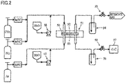
- N 2 gas permeability was conducted using a CO 2 gas separation apparatus including a CO 2 gas separation membrane module 51 as shown in Fig. 2 .
- gas separation membranes I, IV and VI prepared in Example 1, Example 4 and Comparative Example 2, respectively, were cut into pieces of appropriate size to form flat membranes, and each of these membranes was fixed between a feed side 52 (corresponding the above-mentioned gas feeding part) and a permeate side 53 of stainless-steel CO 2 separation membrane module 51.
- N 2 gas at room temperature was fed to feed side 52 of CO 2 gas separation membrane module 51, and then the pressure on feed side 52 was increased to 900 kPaA.
- the pressure on permeate side 53 was controlled at atmospheric pressure.
- N 2 permeance was calculated based on the change of the pressure on feed side 52 from moment to moment.
- Samples were graded as acceptable when N 2 permeance [mol/(m 2 ⁇ s ⁇ kPa)] was lower than or equal to 5 x 10 -8 mol/(m 2 ⁇ s ⁇ kPa).
- Table 1 Acceptance ratio % (Acceptable samples/ Tested samples)
- Example 4 100 (10/10) Comparative Example 2 70 (7/10)
- CO 2 separation was performed using a CO 2 gas separation apparatus including CO 2 gas separation membrane module 51 as shown in Fig. 2 .
- gas separation membranes I to VI prepared in Examples 1 to 4 and Comparative Examples 1 and 2, respectively, were cut into pieces of appropriate size to form flat membranes, and each of these membranes was fixed between feed side 52 (corresponding to the above-mentioned gas feeding part) and permeate side 53 of stainless-steel CO 2 separation membrane module 51.
- a raw gas (CO 2 : 34.5%, N 2 : 52.8%, H 2 O: 12.7%) was fed to feed side 52 of CO 2 gas separation membrane module 51 at a flow rate of 7.03 x 10 -2 mol/min, and a sweep gas (H 2 O: 100%) was fed to permeate side 53 of CO 2 gas separation membrane module 51 at a flow rate of 1.05 x 10 -2 mol/min.
- a sweep gas H 2 O: 100%
- the pressure on feed side 52 was controlled at 900 kPaA by a back-pressure controller 55 provided on the downstream side of a cold trap 54 located about midway in a discharge passage for discharging retentate gas.
- a back-pressure controller 59 was provided between a cold trap 56 and a gas chromatograph 57, and was used to control the pressure on permeate side 53 at atmospheric pressure.
- the flow rate of gas after removal of water vapor by cold trap 56 from the sweep gas discharged through permeate side 53 was quantified based on results of analysis with gas chromatograph 57 to calculate CO 2 permeance and N 2 permeance [mol/(m 2 ⁇ s ⁇ kPa)] regarding CO 2 and N 2 contained in the permeate gas. Then, CO 2 /N 2 permeance ratio was calculated to determine the selectivity (CO 2 permselectivity). The results are shown in Table 2.
- CO 2 gas separation membrane module 51 and pipes for feeding raw gas and sweep gas to CO 2 gas separation membrane module 51 were disposed in a thermostatic chamber (not shown) set at a predetermined temperature in order to maintain CO 2 gas separation membrane module 51 as well as the raw and sweep gases at constant temperature.
- This evaluation of CO 2 separation performance was conducted under conditions that the temperature of CO 2 gas separation membrane module 51 and those of raw and sweep gases were maintained at 110°C.
- the gas separation membrane of the present invention can be utilized to separate CO 2 from a CO 2 -containing gas mixture at a high permselectivity coefficient, for example, in a decarbonation step of large-scale processes such as hydrogen or urea production, or in a CO 2 -permeable membrane reactor.
- 2 Laminate
- 3 Gas-collecting tube
- M Spiral-wound CO 2 gas separation membrane module
- 21 CO 2 gas separation membrane
- 22 Feed-side channel member
- 23 Permeate-side channel member
- 24 Inlet
- 25 Outlet
- 31 Hole
- 32 Outlet
- 50 CO 2 gas separation membrane
- 51 CO 2 gas separation membrane module
- 52 Feed side of CO 2 gas separation membrane module
- 53 Permeate side of CO 2 gas separation membrane module
- 54, 56 Cold trap
- 55, 59 Back-pressure controller
- 57 Gas chromatograph
- 58, 60 Fluid-forwarding pump
Landscapes
- Chemical & Material Sciences (AREA)
- Chemical Kinetics & Catalysis (AREA)
- Engineering & Computer Science (AREA)
- Dispersion Chemistry (AREA)
- Inorganic Chemistry (AREA)
- Health & Medical Sciences (AREA)
- Medicinal Chemistry (AREA)
- Polymers & Plastics (AREA)
- Organic Chemistry (AREA)
- Analytical Chemistry (AREA)
- General Chemical & Material Sciences (AREA)
- Oil, Petroleum & Natural Gas (AREA)
- Manufacturing & Machinery (AREA)
- Separation Using Semi-Permeable Membranes (AREA)
Abstract
Description
- The present invention relates to a gas separation membrane for separating CO2 from a gas mixture that contains at least CO2 and water vapor, a method for manufacturing the membrane, a gas separation membrane module including the gas separation membrane, and others.
- Gas membrane separation processes have received attention in recent years because of their capability of achieving energy conservation when used as a process for separating CO2 from various gases such as natural or exhaust gases as well as synthetic gases that are synthesized in large-scale plants for hydrogen or urea production.
- Various separation membranes have been hitherto proposed as gas separation membranes for use in these gas membrane separation processes. For example, it is proposed in Japanese Patent Laying-Open No.
07-112122 - Examples of gas separation membranes that employ a polyacrylic acid as a hydrogelable polymeric material include a CO2 separation film proposed in Japanese
- Patent Laying-Open No.
08-193156 2013-049048 -
- PTD 1: Japanese Patent Laying-Open No.
07-112122 - PTD 2: Japanese Patent Laying-Open No.
08-193156 - PTD 3: Japanese Patent Laying-Open No.
2013-049048 - However, those gas separation membranes proposed hitherto have been still unsatisfactory in their CO2 permeance and CO2 selectivity.
- It is an object of the present invention to provide a gas separation membrane having high CO2 permselectivity and a method for manufacturing the membrane; and a gas separation membrane module and a gas separation apparatus including the gas separation membrane.
- The present invention provides a CO2 gas separation membrane, a method for manufacturing the CO2 gas separation membrane, a method for separating CO2, a CO2 gas separation membrane module and a CO2 gas separation apparatus described below.
- [1] A CO2 gas separation membrane, including:
- a first layer (A) containing at least one alkali metal compound selected from the group consisting of an alkali metal carbonate, an alkali metal bicarbonate and an alkali metal hydroxide, and a first resin in which a polymer having a carboxyl group has been crosslinked;
- a second layer (B) containing at least one alkali metal compound selected from the group consisting of an alkali metal carbonate, an alkali metal bicarbonate and an alkali metal hydroxide, and a second resin having a structural unit derived from a vinyl ester of a fatty acid; and
- a hydrophobic porous membrane (C).
- [2] The CO2 gas separation membrane according to [1], wherein
the second resin is a polyvinyl alcohol or vinyl alcohol-acrylic acid copolymer, the polyvinyl alcohol or the vinyl alcohol-acrylic acid copolymer being a partially saponified product of a vinyl ester of a fatty acid. - [3] The CO2 gas separation membrane according to [1] or [2], wherein
a surface of the first layer (A) is in contact with a surface of the second layer (B), and a surface of the hydrophobic porous membrane (C) is in contact with one of the other surface of the first layer (A) and the other surface of the second layer (B). - [4] The CO2 gas separation membrane according to [3], wherein
a weight per unit area of one of the first layer (A) and the second layer (B), which is not in contact with the hydrophobic porous membrane (C), is higher than that of the other layer in contact with the hydrophobic porous membrane (C). As used herein, the term "weight per unit area" refers to solid weight per unit area of the first layer (A) or the second layer (B). - [5] The CO2 gas separation membrane according to any one of [1] to [4], wherein
the first layer (A), the second layer (B), and the hydrophobic porous membrane (C) are stacked in this order. - [6] The CO2 gas separation membrane according to any one of [1] to [5], wherein
the first resin has a structural unit that is derived from an acrylic or methacrylic acid or a derivative thereof. - [7] The CO2 gas separation membrane according to any one of [1] to [6], wherein
a total amount of alkali metal compounds contained in the first layer (A) and the second layer (B) is 0.5 parts by mass to 20 parts by mass based on 1 part by mass of a total amount of the first and second resins. - [8] The CO2 gas separation membrane according to any one of [1] to [7], wherein
the alkali metal compounds contained in the first layer (A) and the second layer (B) are each a carbonate or hydroxide of at least one alkali metal selected from the group consisting of sodium, potassium, rubidium and cesium. - [9] The CO2 gas separation membrane according to any one of [1] to [8], wherein
the alkali metal compounds contained in the first layer (A) and the second layer (B) are each cesium carbonate or cesium hydroxide. - [10] The CO2 gas separation membrane according to any one of [1] to [9], wherein
the hydrophobic porous membrane (C) contains at least one material selected from the group consisting of ceramic, a fluorine-containing resin, polyphenylene sulfide, polyether sulfone, and polyimide. - [11] The CO2 gas separation membrane according to any one of [1] to [10], wherein
the hydrophobic porous membrane (C) has pores with an average pore diameter of 0.005 µm to 1.0 µm. - [12] A method for manufacturing the CO2 gas separation membrane according to any one of [1] to [11], including:
- a first step of applying a first coating liquid containing the alkali metal compound, the first resin and a medium or a second coating liquid containing the alkali metal compound, the second resin and a medium onto at least one surface of the hydrophobic porous membrane (C);
- a second step of forming the first layer (A) or the second layer (B) by removing the medium from a coating obtained in the first step;
- a third step of applying one of the first coating liquid and the second coating liquid, which is different from the coating liquid used in the first step, onto a surface of the first layer (A) or the second layer (B) formed in the second step; and
- a fourth step of forming the first layer (A) or the second layer (B) by removing the medium from a coating obtained in the third step.
- [13] The method according to [12], wherein
the first step is a step of applying the second coating liquid onto at least one surface of the hydrophobic porous membrane (C). - [14] A method for separating CO2, including the steps of:
- feeding a gas mixture that contains at least CO2 and water vapor on a surface side of the CO2 gas separation membrane according to any one of [1] to [11]; and
- recovering CO2 separated from the gas mixture through the other surface side of the CO2 gas separation membrane.
- [15] A CO2 gas separation membrane module including the CO2 gas separation membrane according to any one of [1] to [11].
- [16] A CO2 gas separation apparatus, including:
- the CO2 gas separation membrane module according to [15]; and
- a gas feeding part for feeding a gas mixture that contains at least CO2 and water vapor to the CO2 gas separation membrane module.
- The present invention can provide a gas separation membrane having high CO2 permselectivity and a method for manufacturing the membrane; and a gas separation membrane module and a gas separation apparatus including the gas separation membrane.
-
-
Fig. 1 is a schematic view with partial cutaway showing a structure of a spiral-wound CO2 gas separation membrane module including a gas separation membrane of the present invention. -
Fig. 2 is a schematic view showing a CO2 gas separation apparatus including a CO2 gas separation membrane module used in examples. - The CO2 gas separation membrane of the present invention includes the first layer (A), the second layer (B) and the hydrophobic porous membrane (C) described below:
- (A) the first layer containing at least one alkali metal compound selected from the group consisting of an alkali metal carbonate, an alkali metal bicarbonate and an alkali metal hydroxide, and a resin (first resin) in which a polymer having a carboxyl group has been crosslinked;
- (B) the second layer containing at least one alkali metal compound selected from the group consisting of an alkali metal carbonate, an alkali metal bicarbonate and an alkali metal hydroxide, and a resin (second resin) having a structural unit derived from a vinyl ester of a fatty acid; and
- (C) the hydrophobic porous membrane.
- The first resin contained in the first layer (A) includes a crosslinked resin in which a carboxyl group-containing polymer has been crosslinked. The first resin has a network structure where carboxyl group-containing polymer chains are crosslinked with each other. The first resin is preferably used for improvement of water retention property of the CO2 gas separation membrane as well as enhancement of pressure capacity thereof. The CO2 gas separation membrane needs to have some pressure resistance because a large pressure difference is applied as a driving force for gas permeation through the membrane. One or more types of the first resin may be used alone or in combination.
- Examples of the polymer having a carboxyl group include polymers obtained by polymerization of a monomer composition including one or more carboxyl group-containing monomers such as acrylic acid, itaconic acid, crotonic acid and methacrylic acid. Specific examples of the polymer include a polyacrylic acid, a polyitaconic acid, a polycrotonic acid, a polymethacrylic acid, an acrylic acid-methacrylic acid copolymer, an acrylic acid-methyl methacrylate copolymer, and a methacrylic acid-methyl methacrylate copolymer. Especially, the polymer having a carboxyl group preferably contains a structural unit derived from an acrylic or methacrylic acid or a derivative thereof. Specifically, the polymer having a carboxyl group is preferably a polyacrylic acid that is a polymer of acrylic acid, a polymethacrylic acid that is a polymer of methacrylic acid or an acrylic acid-methacrylic acid copolymer that is a copolymer of acrylic acid and methacrylic acid, and is more preferably a polyacrylic acid.
- The first resin may be prepared by a reaction between a polymer having a carboxyl group and a crosslinking agent, or may be prepared by polymerizing a crosslinkable monomer with a monomer having a carboxyl group or an alkyl ester group that can undergo hydrolysis reaction to form a carboxyl group. The carboxyl groups included in the first resin may be totally or partially substituted with carboxylates through neutralization with a metal ion. The metal ion is preferably an alkali metal cation. Regarding the timing of the neutralization reaction, it is preferred that the neutralization reaction be performed after preparation of the crosslinked first resin. When the first resin has carboxyl groups that are totally or partially substituted with carboxylates, such a resin is also a kind of the first resin.
- Examples of the monomer having an alkyl ester group include: acrylic acid alkyl esters having an alkyl group with 1 to 16 carbon atoms, such as methyl acrylate, ethyl acrylate, propyl acrylate, butyl acrylate, hexyl acrylate, octyl acrylate and lauryl acrylate; itaconic acid alkyl esters having an alkyl group with 1 to 16 carbon atoms, such as methyl itaconate, ethyl itaconate, propyl itaconate, butyl itaconate, hexyl itaconate, octyl itaconate and lauryl itaconate; crotonic acid alkyl esters having an alkyl group with 1 to 16 carbon atoms, such as methyl crotonate, ethyl crotonate, propyl crotonate, butyl crotonate, hexyl crotonate, octyl crotonate and lauryl crotonate; and methacrylic acid alkyl esters having an alkyl group with 1 to 16 carbon atoms, such as methyl methacrylate, ethyl methacrylate, propyl methacrylate, butyl methacrylate, hexyl methacrylate, octyl methacrylate and lauryl methacrylate.
- The crosslinkable monomer and the crosslinking agent used in the present invention may be a conventionally known one without any limitation. Examples of the crosslinkable monomer include divinylbenzene, N,N'-methylenebisacrylamide, trimethylolpropane triallyl ether and pentaerythritol tetraallyl ether. Examples of the crosslinking agent include epoxy crosslinking agents, polyvalent glycidyl ethers, polyhydric alcohols, polyvalent isocyanates, polyvalent aziridines, haloepoxy compounds, polyvalent aldehydes, polyvalent amines, organometallic crosslinking agents, and metallic crosslinking agents. It is preferred that the crosslinkable monomer and the crosslinking agent have resistance to alkalis. Any conventionally known approaches may be employed as a method for crosslinking, including thermal crosslinking, ultraviolet crosslinking, electron beam crosslinking, radiation crosslinking, photocrosslinking, and a method described in Japanese Patent Laying-Open No.
2003-268009 07-088171 - The first resin may be commercially available one. Examples of the resins having crosslinked polyacrylic acids include AQUPEC (registered trademark, manufactured by SUMITOMO SEIKA CHEMICALS CO., LTD.) and SANFRESH (registered trademark, manufactured by Sanyo Chemical Industries, Ltd.).
- The CO2 gas separation membrane of the present invention includes the first layer (A), the second layer (B) and the hydrophobic porous membrane (C). In comparison with the CO2 gas separation membrane that includes only the first layer (A) containing the first resin in which a polymer having a carboxyl group has been crosslinked and the hydrophobic porous membrane (C), the second layer (B) added therein, i.e. the layer containing the second resin having a structural unit derived from a vinyl ester of a fatty acid, can improve film-forming property. One or more types of the second resin may be used alone or in combination.
- The second resin may be one which is obtained by partial saponification of a structural unit derived from a vinyl ester of a fatty acid. When saponified, the structural unit derived from a vinyl ester of a fatty acid provides a hydrophilic vinyl alcohol unit. Therefore, when the second resin has in its structure some residual structural unit derived from a vinyl ester of a fatty acid that is hydrophobic, this hydrophobic fatty acid vinyl ester-derived structural unit has an affinity for the hydrophobic porous membrane (C), which reduces membrane defects such as pinholes, and thus improves the film-forming property. As used herein, the term "degree of saponification" refers to what percentage of the structural unit derived from a vinyl ester of a fatty acid is saponified (hydrolyzed). The degree of saponification is preferably greater than or equal to 50% but less than 100%, more preferably greater than or equal to 60% but less than 100%. The degree of saponification can be adjusted with reference to, for example, Japanese Patent Laying-Open Nos.
52-107096 52-27455 Patent No. 5598630 - The second resin may have the structural unit derived from a vinyl ester of a fatty acid with 2 to 16 carbon atoms, such as vinyl acetate, vinyl propionate, vinyl butyrate, vinyl caproate, vinyl laurate, vinyl palmitate, vinyl stearate and vinyl versatate. Examples of the resin include those obtained by partial saponification of the structural unit derived from the above-mentioned vinyl esters of fatty acids, such as polyvinyl alcohol, a vinyl alcohol-ethylene copolymer, a vinyl alcohol-acrylic acid copolymer, a vinyl alcohol-methacrylic acid copolymer, and a vinyl alcohol-vinylsulfonic acid copolymer. Especially, the second resin is preferably a polyvinyl alcohol or vinyl alcohol-acrylic acid copolymer, each of which is obtained by partial saponification of the structural unit derived from the vinyl ester of a fatty acid.
- When the second resin used is one of carboxyl group-containing polymers such as a vinyl alcohol-acrylic acid copolymer, the carboxyl groups may be totally or partially substituted with carboxylates through neutralization with a metal ion as in the first resin. The metal ion is preferably an alkali metal cation. When the second resin has carboxyl groups that are totally or partially substituted with carboxylates, such a resin is also a kind of the second resin.
- The CO2 gas separation membrane of the present invention achieves high permselectinity for a specific gas due to a facilitated transport mechanism that includes a substance, called a CO2 carrier, capable of making reversible reaction with CO2 to facilitate permeation of a specific gas in the form of a reaction product with the CO2 carrier, as well as a solution-diffusion mechanism that utilizes a difference in solubility and diffusivity of gas molecules in a membrane. The following formula (1) represents a reaction between CO2 and a CO2 carrier when the CO2 carrier used therein is cesium carbonate (Cs2CO3). The reaction represented by the following formula (1) is a reversible reaction.
[Formula 1]
CO2 + Cs2CO3 + H2O ⇄ 2CsHCO3 (1)
- The first layer (A) and the second layer (B) in the CO2 gas separation membrane of the present invention each contain at least one alkali metal compound (hereinafter sometimes referred to as "CO2 carrier") selected from the group consisting of an alkali metal carbonate, an alkali metal bicarbonate and an alkali metal hydroxide. The CO2 carrier, as expressed by the formula (1), undergoes the reversible reaction with CO2 which has been dissolved in water in the first layer (A) and the second layer (B), so that the carrier can play a role in selective permeation of CO2. The first layer (A) and the second layer (B) may each contain one or more types of the CO2 carrier.
- The alkali metal compounds ("CO2 carriers") contained in the first layer (A) and the second layer (B) are each preferably a carbonate, bicarbonate or hydroxide of at least one alkali metal selected from the group consisting of sodium, potassium, rubidium and cesium, more preferably a carbonate or hydroxide thereof. Examples of the alkali metal carbonate include sodium carbonate, potassium carbonate, rubidium carbonate, and cesium carbonate. Examples of the alkali metal bicarbonate include sodium bicarbonate, potassium bicarbonate, rubidium bicarbonate, and cesium bicarbonate. Examples of the alkali metal hydroxide include sodium hydroxide, potassium hydroxide, rubidium hydroxide, and cesium hydroxide.
- Further preferably, the alkali metal compounds ("CO2 carriers") contained in the first layer (A) and the second layer (B) are each an alkali metal carbonate or alkali metal hydroxide which is deliquescent, particularly preferably cesium carbonate or cesium hydroxide having a high water solubility.
- For the purpose of further improving CO2 permeance, it is preferred that carboxyl groups contained in the first and second resins be neutralized by cations of alkali metal included in the CO2 carrier so that the alkali metal carbonate, alkali metal bicarbonate or alkali metal hydroxide added can function as a CO2 carrier.
- The first layer (A) and the second layer (B) in the CO2 gas separation membrane of the present invention may contain, in addition to the alkali metal compound derived from the CO2 carrier, various alkali metal compounds such as those used in neutralization of the carboxyl groups contained in the first and second resins. The total amount of alkali metal compounds contained in the first layer (A) and the second layer (B) of the CO2 gas separation membrane is preferably 0.5 parts by mass to 20 parts by mass based on 1 part by mass of a total amount of the first and second resins. When the total amount of alkali metal compounds contained is less than 0.5 parts by mass based on 1 part by mass of the total amount of the first and second resins, the desired CO2 permselectivity may not be obtained. On the other hand, when the total amount of alkali metal compounds contained is greater than 20 parts by mass based on 1 part by mass of the total amount of the first and second resins, the film-forming property may be impaired. The total amount of alkali metal compounds contained is more preferably 1 part by mass to 15 parts by mass based on 1 part by mass of the total amount of the first and second resins.
- The type of alkali metal compound in the first layer (A) may be the same as or different from that in the second layer (B). The first layer (A) and the second layer (B) may each contain only one type of the alkali metal compound or two or more types of such compounds.
- The CO2 gas separation membrane of the present invention has the hydrophobic porous membrane (C) that is a hydrophobic porous membrane with high gas permeability that does not have a gas diffusion resistance against a gas component that has permeated through the membrane. When the first layer (A) or second layer (B) is placed in contact with a surface of the porous membrane, the use of the hydrophobic porous membrane (C) as the porous membrane may prevent water in the first layer (A) or the second layer (B) from entering the pores of the porous membrane, and thereby suppress reduction in CO2 permeance. The layer placed in contact with a surface of the hydrophobic porous membrane (C) is preferably the second layer (B). In this case, the first layer (A) is placed in contact with the surface (outer surface) of the second layer (B) on the side not in contact with the hydrophobic porous membrane (C).
- In the process of the hydrogen or urea production to which the CO2 gas separation membrane of the present invention is to be applied, the gas separation membrane may be used at a temperature of higher than or equal to 100°C. Therefore, it is preferred that the hydrophobic porous membrane (C) or other members included in the gas separation membrane have a heat resistance of higher than or equal to 100°C.
- The term "hydrophobic" means that the water contact angle at 25°C is greater than or equal to 90°C. The "heat resistance of higher than or equal to 100°C" means that a member such as the porous membrane can be kept under a temperature condition of higher than or equal to 100°C for 2 hours or longer in the same form maintained as before being kept under such a condition, without visible curling of the membrane due to heat shrinkage or thermal fusion.
- The hydrophobic porous membrane (C) may be made from, for example, polyethylene, polypropylene or other polyolefin resins; polytetrafluoroethylene (PTFE), polyvinyl fluoride, polyvinylidene fluoride or other fluorine-containing resins; polyphenylene sulfide; polyether sulfone; polyimide; high molecular weight polyester; heat resistant polyamide; aramid; polycarbonate or other resin materials; or metals, glass, ceramic or other inorganic materials. Among these materials, PTFE, polyvinyl fluoride, polyvinylidene fluoride or other fluorine-containing resins, polyphenylene sulfide, polyether sulfone, polyimide, or ceramic is preferred in terms of water repellency and heat resistance; more preferred is PTFE because it may readily provide micro pore size, and give a high porosity to achieve an increased energy efficiency in gas separation.
- The thickness of the hydrophobic porous membrane (C) is not particularly limited. Usually, from the viewpoint of the mechanical strength, the hydrophobic porous membrane (C) preferably has a thickness of 10 µm to 3000 µm, more preferably 10 µm to 500 µm, further preferably 15 µm to 150 µm.
- While the average size of pores (average pore size) in the hydrophobic porous membrane (C) is not particularly limited, it is preferably smaller than or equal to 10 µm, more preferably 0.005 µm to 1.0 µm from the standpoint of gas permeability. The porosity of the hydrophobic porous membrane (C) is preferably 5% to 99%, more preferably 30% to 90% from the standpoint of energy efficiency in gas separation.
- In stacking the first layer (A) containing the first resin and the second layer (B) containing the second resin, the stacking order of the layers is not limited in the CO2 gas separation membrane of the present invention. For example, a surface of the first layer (A) containing the first resin is in contact with a surface of the second layer (B) containing the second resin; and either the other surface of the first layer (A) or the other surface of the second layer (B) is in contact with a surface of the hydrophobic porous membrane (C) to form the laminate structure including the first layer (A), the second layer (B) and the hydrophobic porous membrane (C). In this case, it is preferred from the standpoint of CO2 permeance that a weight per unit area (solid weight per unit area) of one of the first layer (A) and the second layer (B), which is not in contact with the hydrophobic porous membrane (C), is higher than that of the other layer in contact with the hydrophobic porous membrane (C). Moreover, from the standpoint of CO2 permeance, preferably the stacking order of the membrane structure is as follows: the first layer (A) containing the first resin that has a higher water retention capacity than the second resin has; the second layer (B) containing the second resin; and the hydrophobic porous membrane (C).
- The first layer (A) and the second layer (B) may contain a CO2 hydration catalyst in addition to the CO2 carrier.
- The CO2 hydration catalyst is a catalyst that increases the rate of reaction in the CO2 hydration reaction represented by the following formula (2). The reaction represented by the following formula (2) is a reversible reaction.
[Formula 2]
CO2 + H2O ⇄ HCO3 - + H+ (2)
- An overall reaction equation of a reaction between CO2 and the CO2 carrier may be represented by the following formula (3), wherein it is assumed that the CO2 carrier is a carbonate. The reaction represented by the following formula (3) is a reversible reaction. The above-mentioned CO2 hydration reaction which is an elementary reaction for the reaction of formula (3) proceeds at a slow rate under a catalyst-free condition. Thus, the addition of the catalyst accelerates the elementary reaction, thereby accelerating the reaction between CO2 and the CO2 carrier; as a result, the rate of the CO2 permeation is expected to be increased.
[Formula 3]
CO2 + H2O + CO3 - ⇄ 2HCO3 - (3)
- Therefore, the inclusion of the CO2 carrier and CO2 hydration catalyst in the first layer (A) and the second layer (B) accelerates the reaction between CO2 and the CO2 carrier, and results in significantly improved CO2 permeance and CO2 permselectivity. Since the CO2 hydration catalyst can function effectively even under a high partial pressure of CO2, the CO2 permeance and CO2 permselectivity under a high partial pressure of CO2 may also be significantly improved.
- The CO2 hydration catalyst preferably contains an oxoacid compound, particularly, an oxoacid compound with at least one element selected from Group 14, 15 and 16 elements, and more preferably contains at least one of a tellurious acid compound, a selenious acid compound, an arsenious acid compound and an orthosilicic acid compound. More specifically, potassium tellurite (K2TeO3, melting point: 465°C), sodium tellurite (Na2TeO3, melting point: 710°C), lithium tellurite (Li2O3Te, melting point: about 750°C), potassium selenite (K2O3Se, melting point: 875°C), sodium arsenite (NaO2As, melting point: 615°C), sodium orthosilicate (Na4O4Si, melting point: 1018°C) or the like may be suitably used. Among these, a tellurious acid compound is more preferred, and further preferred is potassium tellurite or sodium tellurite. The first layer (A) and the second layer (B) may each contain one or more CO2 hydration catalysts.
- When the CO2 hydration catalyst has a melting point of higher than or equal to 200°C, the catalyst may be present with thermal stability in a hydrophilic resin-containing layer, and therefore it is possible to maintain the performance of the CO2 gas separation membrane for a long period of time. If the CO2 hydration catalyst is soluble in water, the separation-functional layer that contains the CO2 hydration catalyst may be prepared in an easy and stable manner. When a tellurious acid compound, an arsenious acid compound or a selenious acid compound is used as the CO2 hydration catalyst, it can be expected that the membrane would be provided with improved performance in a stable manner because any of these compounds is soluble in water and has a melting point of higher than or equal to 200°C.
- The method for manufacturing the CO2 gas separation membrane of the present invention will be described. In the first step, a first coating liquid containing: the alkali metal compound; the first resin in which a polymer having a carboxyl group has been crosslinked; and a medium, or a second coating liquid containing: the alkali metal compound; the second resin having a structural unit derived from a vinyl ester of a fatty acid; and a medium is applied onto at least one surface of the hydrophobic porous membrane (C).
- Examples of the medium used for preparing the first coating liquid 1 and the second coating liquid include polar protonic media such as water, methanol, ethanol, 1-propanol, 2-propanol and other alcohols; non-polar media such as toluene, xylene and hexane; and polar aprotic media such as acetone, methyl ethyl ketone, methyl isobutyl ketone or other ketones, N-methylpyrrolidone, N,N-dimethylacetamide and N,N-dimethylformamide. These media may be used alone or in admixture of two or more thereof as long as they are compatible. Among these, preferred media are those containing at least one selected from the group consisting of water, methanol, ethanol, 1-propanol, 2-propanol and other alcohols. More preferred media are those containing water.
- The temperature of the coating liquid in its application onto the hydrophobic porous membrane (C) can be selected as appropriate in accordance with the composition or concentration of the liquid. If the temperature is excessively high, however, a large amount of the medium may be vaporized from the coating liquid and the composition and concentration of the liquid may be changed, or scars may be left by vaporization on the coating (coating layer). Therefore, the temperature of the coating liquid is preferably higher than or equal to room temperature and lower than or equal to a temperature 5°C below the boiling point of the medium to be employed. For example, if water is employed as the medium, it is preferred that the coating liquid be applied onto the hydrophobic porous membrane (C) at a temperature of 15°C to 95°C.
- The coating liquid can be applied onto the hydrophobic porous membrane (C) by any method that is not particularly limited. Examples of such application method include spin coating, bar coating, die coating, blade coating, air knife coating, gravure coating, roll coating, spray coating, dip coating, comma roll coating, kiss coating, screen printing and ink jet printing. It is preferred that the amount of the coating liquid applied be adjusted according to the type of resin contained in the coating liquid. When the coating liquid used contains the first resin, the weight thereof per unit area (solid weight per unit area) is, for example, 0.1 g/m2 to 1000 g/m2, preferably 0.1 g/m2 to 500 g/m2, more preferably 0.5 g/m2 to 300 g/m2, further preferably 1 g/m2 to 100 g/m2. When the coating liquid used contains the second resin, the weight thereof per unit area is, for example, 1 g/m2 to 1000 g/m2, preferably 2 g/m2 to 750 g/m2, more preferably 4 g/m2 to 500 g/m2, further preferably 5 g/m2 to 100 g/m2. It is possible to control these weights per unit area by optimizing the coating formation speed (that is, for example, the feed rate of the hydrophobic porous membrane (C) on which the coating liquid is to be applied), the concentration or discharge rate of the coating liquid, or other factors.
- In the second step, the medium is removed from the coating (coating layer) formed in the first step to prepare the first layer (A) or the second layer (B). The medium can be removed by any method without limitation. While any conventionally known method may be used to remove the medium, it is preferred to employ such a method that the coating is dried by forced-air drying with heated air or the like to remove the medium by evaporation. For example, the coating is conveyed into a forced-air dryer set at a predetermined temperature and a predetermined humidity to remove the medium from the coating by evaporation. The first layer (A) or the second layer (B) is formed by this operation.
- The drying temperature may be selected as appropriate according to the medium of the coating liquid and the type of the hydrophobic porous membrane (C). Usually, it is preferred that the drying temperature be higher than the freezing point of the medium and lower than the melting point of the hydrophobic porous membrane (C). Generally, a suitable temperature is 80°C to 200°C.
- The medium removal operation is performed until the concentration of the medium in the coating is decreased to a predetermined level or lower. Specifically, it is preferred that the removal operation be performed until the medium content in the first layer (A) or the second layer (B) obtained in the second step reaches 1 % by weight to 34% by weight.
- In the third step, one of the first coating liquid and the second coating liquid, which is different from the coating liquid used in the first step, is applied onto a surface (outer surface) of the first layer (A) or the second layer (B) prepared in the second step. The coating liquid is preferably applied by the same method as that used in the first step for coating liquid application, although it is possible to employ a different method. The temperature of the coating liquid in its application in the third step, as in the first step, can be selected as appropriate in accordance with the composition or concentration of the liquid applied. It is preferred that the amount of the coating liquid applied be adjusted according to the type of resin contained in the coating liquid, as in the first step.
- In the fourth step, the first layer (A) or the second layer (B) is prepared by removing the medium from the coating (coating layer) obtained in the third step. The medium is preferably removed by the same method as that used in the second step, although it is possible to employ a different method. The drying temperature may be selected as appropriate according to the medium of the coating liquid and the type of the hydrophobic porous membrane (C), as in the second step.
- The CO2 gas separation membrane is preferably manufactured by the method wherein the second coating liquid is applied onto at least one surface of the hydrophobic porous membrane (C) in the first step; the second layer (B) is prepared in the second step; the first coating liquid is applied onto a surface of the second layer (B) in the third step; and the first layer (A) is obtained in the fourth step. When this method is employed, it is preferred that the weights per unit area of the first layer (A) containing the first resin and of the second layer (B) containing the second resin be 2 g/m2 to 500 g/m2 and 1 g/m2 to 20 g/m2, respectively, and it is more preferred that the weights per unit area of the first layer (A) containing the first resin and of the second layer (B) containing the second resin be 10 g/m2 to 300 g/m2 and 2 g/m2 to 15 g/m2, respectively, from the standpoint of CO2 permselectivity. Furthermore, the weight per unit area of the first layer (A) is preferably greater than that of the second layer (B) from the standpoint of CO2 permselectivity. The proportion of the weight per unit area of the second layer (B) to that of the first layer (A) (hereinafter also referred to as "proportion of the weight per unit area" simply), that is, the value obtained by dividing the weight per unit area of the second layer (B) by that of the first layer (A), is preferably within the range of from 0.04 to 0.5, more preferably within the range of from 0.05 to 0.2.
- The CO2 gas separation membrane module of the present invention includes the CO2 gas separation membrane of the present invention, and may be of any type such as spiral-wound type, tube type, hollow fiber type, pleated type, and plate-and-frame type.
Fig. 1 shows a schematic view with partial cutaway showing a structure of a spiral-wound CO2 gas separation membrane module including the CO2 gas separation membrane of the present invention. - A spiral-wound CO2 gas separation membrane module M shown in
Fig. 1 has a structure in which a laminate 2 is plurally wrapped around an outer periphery of a hollow gas-collectingtube 3 with a plurality ofholes 31 formed therein, laminate 2 including a CO2gas separation membrane 21, a feed-side channel member 22 and a permeate-side channel member 23 in a laminated manner. It is preferred that feed-side channel member 22 and permeate-side channel member 23 have the capability of accelerating turbulent flow of a gas mixture fed containing CO2 and water vapor and a permeate gas that has permeated through CO2 gas separation membrane 21 (surface renewal of the membrane surface) to increase the rate of permeation of CO2 in the fed fluid through the membratne; and the capability of minimizing pressure drop at the feed side. Feed-side channel member 22 and permeate-side channel member 23 that are of mesh type may be suitably employed because these members preferably have the capability of serving as a spacer and the capability of generating turbulent flow in the gas mixture. The unit cell of the mesh may have a shape selected from, for example, rhombus, parallelogram and others according to the intended use, considering that the flow path of the gas mixture may be changed by the shape of the mesh. While feed-side channel member 22 and permeate-side channel member 23 may be made from any material without limitation, it is preferred that a heat-resistant material be employed because the gas separation membrane of the present invention will be used under a temperature condition of higher than or equal to 100°C. The same materials as those of the hydrophobic porous membrane (C) listed above are preferably employed for the feed-side and permeate-side channel members. - The CO2 gas separation apparatus of the present invention includes the CO2 gas separation membrane module of the present invention and a gas feeding part for feeding a gas mixture that contains at least CO2 and water vapor to the CO2 gas separation membrane module. The gas feeding part includes an inlet for feeding the gas mixture that contains CO2 and water vapor on a surface side of the CO2 gas separation membrane, and may exist as the inlet of the CO2 gas separation membrane module, or may be a gas feeding member enclosing the CO2 gas separation membrane module in its container-shaped structure that has an internal feed-side space communicated with the inlet of the enclosed CO2 gas separation membrane module. The inlet may be located on a surface of the CO2 gas separation membrane or of the laminate including the membrane, or may be at an end face of the CO2 gas separation membrane or of the laminate including the membrane. For example, in spiral-wound CO2 gas separation membrane module M shown in
Fig. 1 , aninlet 24 may be located at one or both of the end faces of CO2gas separation membrane 21 or of laminate 2 including the membrane. - The method for separating CO2 of the present invention includes the steps of: feeding a gas mixture that contains at least CO2 and water vapor on a surface side of the CO2 gas separation membrane according to the present invention; and recovering CO2 separated from the gas mixture through the other surface side of the CO2 gas separation membrane. In spiral-wound CO2 gas separation membrane module M of the above-mentioned structure, the gas mixture containing CO2 and water vapor is fed through
inlet 24 provided in CO2 gas separation membrane module M in the direction of arrow A, and during flowing through feed-side channel member 22, CO2 in the gas mixture permeates through CO2gas separation membrane 21. The permeated CO2 flows through permeate-side channel member 23, is collected in gas-collectingtube 3, and is then recovered through anoutlet 32 of gas-collectingtube 3. The retentate gas mixture after CO2 separation passes through a space of feed-side channel member 22, and is discharged from anoutlet 25 of CO2 gas separation membrane module M. A sweep gas selected from inert gases or others may be fed to gas-collectingtube 3. - The present invention is further illustrated, but is not to be construed as limited, by the following examples.
- A mixture was prepared by stirring 80 g of water and 2 g of a crosslinked polyacrylic acid ("AQUPEC HV-501" manufactured by SUMITOMO SEIKA CHEMICALS CO., LTD.). Then, 9.3 g of cesium carbonate and 0.7 g of potassium tellurite were added to the mixture, and further mixed by stirring to prepare coating liquid I-1.
- Another mixture was prepared by stirring 80 g of water and 4.2 g of a vinyl alcohol-acrylic acid copolymer (degree of saponification: 82%, carboxyl groups of acrylic acid units form Cs salt) obtained by the production method according to Patent No.
5598630 - Subsequently, the prepared coating liquid I-2 was applied onto the surface of a hydrophobic PTFE porous membrane ("POREFLON HP-010-50", membrane thickness: 50 µm, average pore size: 0.1 µm, manufactured by Sumitomo Electric Fine Polymer, Inc.). The hydrophobic PTFE porous membrane with the coating liquid applied thereon was then dried at a temperature of about 120°C for longer than or equal to 5 minutes to form resin layer I-2. Thereafter, coating liquid I-1 was applied onto the surface of resin layer I-2, and was then dried again at a temperature of about 120°C for longer than or equal to 5 minutes to form resin layer I-1 deposited thereon, thereby obtaining sheet-like gas separation membrane I having a CO2 separation-functional layer formed on the hydrophobic PTFE porous membrane. Resin layer I-1 (corresponding to the first layer (A)) had a weight per unit area of 66 g/m2, and resin layer I-2 (corresponding to the second layer (B)) had a weight per unit area of 5 g/m2. The proportion of the weight per unit area was 0.076.
- Gas separation membrane II was obtained in the same manner as in Example 1 except that the amount of cesium carbonate added in the coating liquid I-1 preparation step of Example 1 was increased to 11.6 g to prepare coating liquid II-1. Resin layer II-1 (corresponding to the first layer (A)) had a weight per unit area of 68 g/m2, and resin layer II-2 (corresponding to the second layer (B)) had a weight per unit area of 7.6 g/m2. The proportion of the weight per unit area was 0.11.
- Gas separation membrane III was obtained in the same manner as in Example 1 except that the amount of cesium carbonate added in the coating liquid I-1 preparation step of Example 1 was increased to 14.0 g to prepare coating liquid III-1. Resin layer III-1 (corresponding to the first layer (A)) had a weight per unit area of 79 g/m2, and resin layer III-2 (corresponding to the second layer (B)) had a weight per unit area of 7.6 g/m2. The proportion of the weight per unit area was 0.096.
- A mixture was prepared by stirring 80 g of water and 2 g of a crosslinked polyacrylic acid ("AQUPEC HV-501" manufactured by SUMITOMO SEIKA CHEMICALS CO., LTD.). Then, 9.3 g of cesium carbonate and 0.7 g of potassium tellurite were added to the mixture, and further mixed by stirring to prepare coating liquid IV-1.
- Another mixture was prepared by stirring 80 g of water and 4.2 g of a vinyl alcohol-acrylic acid copolymer (degree of saponification: 82%, carboxyl groups of acrylic acid units form Cs salt) obtained by the production method according to Patent No. 5598630 publication. Then, 9.9 g of cesium carbonate and 1.5 g of potassium tellurite were added to the mixture, and further mixed by stirring to prepare coating liquid IV-2.
- Subsequently, the prepared coating liquid IV-1 was applied onto the surface of a hydrophobic PTFE porous membrane ("POREFLON HP-010-50", membrane thickness: 50 µm, average pore size: 0.1 µm, manufactured by Sumitomo Electric Fine Polymer, Inc.). The hydrophobic PTFE porous membrane with the coating liquid applied thereon was then dried at a temperature of about 120°C for longer than or equal to 5 minutes to form resin layer IV-1. Thereafter, coating liquid IV-2 was applied onto the surface of resin layer IV-1, and was then dried again at a temperature of about 120°C for longer than or equal to 5 minutes to form resin layer IV-2 deposited thereon, thereby obtaining sheet-like gas separation membrane IV having a CO2 separation-functional layer formed on the hydrophobic PTFE porous membrane. Resin layer IV-1 (corresponding to the first layer (A)) had a weight per unit area of 33 g/m2, and resin layer IV-2 (corresponding to the second layer (B)) had a weight per unit area of 60 g/m2. The proportion of the weight per unit area was 1.8. In Example 4, the first layer (A) was formed prior to the second layer (B), and a weight per unit area of the first layer (A) is lower than that of the second layer (B) unlike those in Examples 1 to 3.
- 80 g of water, 3 g of a vinyl alcohol-acrylic acid copolymer (degree of saponification: 82%, carboxyl groups of acrylic acid units form Cs salt) as a hydrophilic resin having a structural unit derived from an aliphatic vinyl ester obtained by the production method according to Patent No.
5598630 publication, 7.0 g of cesium carbonate and 1.1 g of potassium tellurite was mixed by stirring to prepare coating liquid V-2. - Subsequently, the prepared coating liquid V-2 was applied onto the surface of a hydrophobic PTFE porous membrane ("POREFLON HP-010-50", membrane thickness: 50 µm, average pore size: 0.1 µm, manufactured by Sumitomo Electric Fine Polymer, Inc.). The hydrophobic PTFE porous membrane with the coating liquid applied thereon was then dried at a temperature of about 120°C for longer than or equal to 5 minutes to obtain a gas separation membrane having a CO2 separation-functional layer formed on the hydrophobic PTFE porous membrane. The coating liquid application and drying operations were further repeated several times, thereby obtaining sheet-like gas separation membrane V. Gas separation membrane V (corresponding to the second layer (B)) had a weight per unit area of 100 g/m2.
- 188 g of water, 4 g of a crosslinked polyacrylic acid ("AQUPEC HV-501" manufactured by SUMITOMO SEIKA CHEMICALS CO., LTD.) as a hydrophilic resin in which a polymer having a carboxyl group has been crosslinked, and 9.3 g of cesium hydroxide monohydrate was mixed through stirring, thereby carrying out a neutralization reaction. After completion of the neutralization reaction, 9.0 g of cesium carbonate, 1.5 g of potassium tellurite and 1.2 g of a surfactant ("Surflon S-242" manufactured by AGC Seimi Chemical Co., Ltd.) were added thereto, and the materials were mixed to obtain coating liquid VI-1.
- Subsequently, the prepared coating liquid VI-1 was applied onto the surface of a hydrophobic PTFE porous membrane ("POREFLON HP-010-50", membrane thickness: 50 µm, average pore size: 0.1 µm, manufactured by Sumitomo Electric Fine Polymer, Inc.). The hydrophobic PTFE porous membrane with the coating liquid applied thereon was then dried at a temperature of about 120°C for longer than or equal to 5 minutes to obtain a gas separation membrane having a CO2 separation-functional layer formed on the hydrophobic PTFE porous membrane. The coating liquid application and drying operations were further repeated several times, thereby obtaining sheet-like gas separation membrane VI. Gas separation membrane VI (corresponding to the first layer (A)) had a weight per unit area of 100 g/m2.
- Evaluation of N2 gas permeability was conducted using a CO2 gas separation apparatus including a CO2 gas
separation membrane module 51 as shown inFig. 2 . Specifically, gas separation membranes I, IV and VI prepared in Example 1, Example 4 and Comparative Example 2, respectively, were cut into pieces of appropriate size to form flat membranes, and each of these membranes was fixed between a feed side 52 (corresponding the above-mentioned gas feeding part) and apermeate side 53 of stainless-steel CO2separation membrane module 51. - N2 gas at room temperature was fed to feed
side 52 of CO2 gasseparation membrane module 51, and then the pressure onfeed side 52 was increased to 900 kPaA. The pressure onpermeate side 53 was controlled at atmospheric pressure. N2 permeance was calculated based on the change of the pressure onfeed side 52 from moment to moment. Samples were graded as acceptable when N2 permeance [mol/(m2·s·kPa)] was lower than or equal to 5 x 10⁻⁸ mol/(m2·s·kPa). Each ten samples of the gas separation membranes of Examples 1, 4 and Comparative Example 2 were evaluated for their film-forming property. The results are shown in Table 1.[Table 1] Acceptance ratio % (Acceptable samples/ Tested samples) Example 1 100 (10/10) Example 4 100 (10/10) Comparative Example 2 70 (7/10) - CO2 separation was performed using a CO2 gas separation apparatus including CO2 gas
separation membrane module 51 as shown inFig. 2 . Specifically, gas separation membranes I to VI prepared in Examples 1 to 4 and Comparative Examples 1 and 2, respectively, were cut into pieces of appropriate size to form flat membranes, and each of these membranes was fixed between feed side 52 (corresponding to the above-mentioned gas feeding part) and permeateside 53 of stainless-steel CO2separation membrane module 51. - A raw gas (CO2: 34.5%, N2: 52.8%, H2O: 12.7%) was fed to feed
side 52 of CO2 gasseparation membrane module 51 at a flow rate of 7.03 x 10⁻² mol/min, and a sweep gas (H2O: 100%) was fed to permeateside 53 of CO2 gasseparation membrane module 51 at a flow rate of 1.05 x 10⁻² mol/min. It should be noted that water introduced via fluid-forwarding metering pumps 58 and 60 was heated and evaporated to adjust the H2O ratio and flow rates as mentioned above. The pressure onfeed side 52 was controlled at 900 kPaA by a back-pressure controller 55 provided on the downstream side of acold trap 54 located about midway in a discharge passage for discharging retentate gas. In addition, a back-pressure controller 59 was provided between acold trap 56 and agas chromatograph 57, and was used to control the pressure onpermeate side 53 at atmospheric pressure. The flow rate of gas after removal of water vapor bycold trap 56 from the sweep gas discharged throughpermeate side 53 was quantified based on results of analysis withgas chromatograph 57 to calculate CO2 permeance and N2 permeance [mol/(m2·s·kPa)] regarding CO2 and N2 contained in the permeate gas. Then, CO2/N2 permeance ratio was calculated to determine the selectivity (CO2 permselectivity). The results are shown in Table 2. - It should be noted that CO2 gas
separation membrane module 51 and pipes for feeding raw gas and sweep gas to CO2 gasseparation membrane module 51 were disposed in a thermostatic chamber (not shown) set at a predetermined temperature in order to maintain CO2 gasseparation membrane module 51 as well as the raw and sweep gases at constant temperature. This evaluation of CO2 separation performance was conducted under conditions that the temperature of CO2 gas separation membrane module 51 and those of raw and sweep gases were maintained at 110°C.[Table 2] Stacking order First resin-containing layer Second resin-containing layer CO2 permeance CO2/N2 selectivity First resin Alkali metal compound CO2 hydration catalyst Second resin Alkali metal compound CO2 hydration catalyst Type Type Amount added per weight of first resin Type Amount added per weight of first resin Type Degree of saponification Type Amount added per weight of second resin Type Amount added per weight of second resin - - - g/g - g/g - % - g/g - g/g mol/ (m2s kPa) - Example 1 First resin-containing layer Second resin-containing layer Hydrophobic porous membrane Crosslinked polyacrylic acid Cs2CO3 4.7 K2TeO3 0.36 Vinyl alcohol-acrylic acid copolymer (Cs salt) 82 Cs2CO3 2.4 K2TeO3 0.36 3.01 × 10⁻⁵ 707 Example 2 First resin-containing layer Second resin-containing layer Hydrophobic porous membrane Crosslinked polyacrylic acid Cs2CO3 5.8 K2TeO3 0.36 Vinyl alcohol-acrylic acid copolymer (Cs salt) 82 Cs2CO3 2.4 K2TeO3 0.36 3.91 × 10⁻⁵ 934 Example 3 First resin-containing layer Second resin-containing layer Hydrophobic porous membrane Crosslinked polyacrylic acid Cs2CO3 7.0 K2TeO3 0.36 Vinyl alcohol-acrylic acid copolymer (Cs salt) 82 Cs2CO3 2.4 K2TeO3 0.36 3.30 × 10⁻⁵ 710 Example 4 Second resin-containing layer First resin-containing layer Hydrophobic porous membrane Crosslinked polyacrylic acid Cs2CO3 4.7 K2TeO3 0.36 Vinyl alcohol-acrylic acid copolymer (Cs salt) 82 Cs2CO3 2.4 K2TeO3 0.36 2.39 × 10⁻⁵ 872 Comparative Example 1 Second resincontaining layer Hydrophobic porous membrane - - - - - Vinyl alcohol-acrylic acid copolymer (Cs salt) 82 Cs2CO3 2.3 K2TeO3 0.36 2.69 × 10⁻⁵ 294 Comparative Example 2 First resin-containing layer Hydrophobic porous membrane Crosslinked polyacrylic acid CsOH·H2O 2.3 K2TeO3 0.36 - - - - - - 1.98 × 10⁻⁵ 44 Cs2CO3 2.3 - The gas separation membrane of the present invention can be utilized to separate CO2 from a CO2-containing gas mixture at a high permselectivity coefficient, for example, in a decarbonation step of large-scale processes such as hydrogen or urea production, or in a CO2-permeable membrane reactor.
- 2: Laminate, 3: Gas-collecting tube, M: Spiral-wound CO2 gas separation membrane module, 21: CO2 gas separation membrane, 22: Feed-side channel member, 23: Permeate-side channel member, 24: Inlet, 25: Outlet, 31: Hole, 32: Outlet, 50: CO2 gas separation membrane, 51: CO2 gas separation membrane module, 52: Feed side of CO2 gas separation membrane module, 53: Permeate side of CO2 gas separation membrane module, 54, 56: Cold trap, 55, 59: Back-pressure controller, 57: Gas chromatograph, 58, 60: Fluid-forwarding pump
Claims (16)
- A CO2 gas separation membrane, comprising:a first layer (A) including at least one alkali metal compound selected from the group consisting of an alkali metal carbonate, an alkali metal bicarbonate and an alkali metal hydroxide, and a first resin in which a polymer having a carboxyl group has been crosslinked;a second layer (B) including at least one alkali metal compound selected from the group consisting of an alkali metal carbonate, an alkali metal bicarbonate and an alkali metal hydroxide, and a second resin having a structural unit derived from a vinyl ester of a fatty acid; anda hydrophobic porous membrane (C).
- The CO2 gas separation membrane according to claim 1, wherein
the second resin is a polyvinyl alcohol or vinyl alcohol-acrylic acid copolymer, the polyvinyl alcohol or the vinyl alcohol-acrylic acid copolymer being a partially saponified product of a vinyl ester of a fatty acid. - The CO2 gas separation membrane according to claim 1 or 2, wherein
a surface of the first layer (A) is in contact with a surface of the second layer (B), and a surface of the hydrophobic porous membrane (C) is in contact with one of the other surface of the first layer (A) and the other surface of the second layer (B). - The CO2 gas separation membrane according to claim 3, wherein
a weight per unit area of one of the first layer (A) and the second layer (B), which is not in contact with the hydrophobic porous membrane (C), is higher than that of the other layer in contact with the hydrophobic porous membrane (C). - The CO2 gas separation membrane according to any one of claims 1 to 4, wherein
the first layer (A), the second layer (B), and the hydrophobic porous membrane (C) are stacked in this order. - The CO2 gas separation membrane according to any one of claims 1 to 5, wherein
the first resin has a structural unit that is derived from an acrylic or methacrylic acid or a derivative thereof. - The CO2 gas separation membrane according to any one of claims 1 to 6, wherein
a total amount of alkali metal compounds contained in the first layer (A) and the second layer (B) is 0.5 parts by mass to 20 parts by mass based on 1 part by mass of a total amount of the first and second resins. - The CO2 gas separation membrane according to any one of claims 1 to 7, wherein
the alkali metal compounds contained in the first layer (A) and the second layer (B) are each a carbonate or hydroxide of at least one alkali metal selected from the group consisting of sodium, potassium, rubidium and cesium. - The CO2 gas separation membrane according to any one of claims 1 to 8, wherein
the alkali metal compounds contained in the first layer (A) and the second layer (B) are each cesium carbonate or cesium hydroxide. - The CO2 gas separation membrane according to any one of claims 1 to 9, wherein
the hydrophobic porous membrane (C) includes at least one material selected from the group consisting of ceramic, a fluorine-containing resin, polyphenylene sulfide, polyether sulfone, and polyimide. - The CO2 gas separation membrane according to any one of claims 1 to 10, wherein
the hydrophobic porous membrane (C) has pores with an average pore diameter of 0.005 µm to 1.0 µm. - A method for manufacturing the CO2 gas separation membrane according to any one of claims 1 to 11, comprising:a first step of applying a first coating liquid containing the alkali metal compound, the first resin and a medium or a second coating liquid containing the alkali metal compound, the second resin and a medium onto at least one surface of the hydrophobic porous membrane (C);a second step of forming the first layer (A) or the second layer (B) by removing the medium from a coating obtained in the first step;a third step of applying one of the first coating liquid and the second coating liquid, which is different from the coating liquid used in the first step, onto a surface of the first layer (A) or the second layer (B) formed in the second step; anda fourth step of forming the first layer (A) or the second layer (B) by removing the medium from a coating obtained in the third step.
- The method according to claim 12, wherein
the first step is a step of applying the second coating liquid onto at least one surface of the hydrophobic porous membrane (C). - A method for separating CO2, comprising the steps of:feeding a gas mixture that contains at least CO2 and water vapor on a surface side of the CO2 gas separation membrane according to any one of claims 1 to 11; andrecovering CO2 separated from the gas mixture through the other surface side of the CO2 gas separation membrane.
- A CO2 gas separation membrane module comprising the CO2 gas separation membrane according to any one of claims 1 to 11.
- A CO2 gas separation apparatus, comprising:the CO2 gas separation membrane module according to claim 15; anda gas feeding part for feeding a gas mixture that contains at least CO2 and water vapor to the CO2 gas separation membrane module.
Applications Claiming Priority (2)
| Application Number | Priority Date | Filing Date | Title |
|---|---|---|---|
| JP2014233186 | 2014-11-18 | ||
| PCT/JP2015/082280 WO2016080400A1 (en) | 2014-11-18 | 2015-11-17 | Carbon dioxide gas separation membrane, method for manufacturing same, and carbon dioxide gas separation membrane module |
Publications (4)
| Publication Number | Publication Date |
|---|---|
| EP3231501A1 true EP3231501A1 (en) | 2017-10-18 |
| EP3231501A4 EP3231501A4 (en) | 2018-06-27 |
| EP3231501C0 EP3231501C0 (en) | 2024-02-28 |
| EP3231501B1 EP3231501B1 (en) | 2024-02-28 |
Family
ID=56013935
Family Applications (1)
| Application Number | Title | Priority Date | Filing Date |
|---|---|---|---|
| EP15861252.3A Active EP3231501B1 (en) | 2014-11-18 | 2015-11-17 | Carbon dioxide gas separation membrane, method for manufacturing same, and carbon dioxide gas separation membrane module |
Country Status (6)
| Country | Link |
|---|---|
| US (1) | US10744454B2 (en) |
| EP (1) | EP3231501B1 (en) |
| JP (1) | JP6645983B2 (en) |
| KR (1) | KR102404068B1 (en) |
| TW (1) | TWI710460B (en) |
| WO (1) | WO2016080400A1 (en) |
Cited By (4)
| Publication number | Priority date | Publication date | Assignee | Title |
|---|---|---|---|---|
| EP3603770A4 (en) * | 2017-11-07 | 2021-01-20 | Sumitomo Chemical Company, Limited | Gas separation device and gas separation method |
| WO2021123863A1 (en) | 2019-12-20 | 2021-06-24 | Total Se | Tubular electrochemical separation unit and manufacturing method therefor |
| EP3851184A4 (en) * | 2018-09-14 | 2022-06-08 | Sumitomo Chemical Company Limited | COMPOSITION USEFUL FOR PRODUCING AN ACID GAS SEPARATION MEMBRANE |
| EP3922344A4 (en) * | 2019-02-05 | 2022-10-26 | Kawasaki Jukogyo Kabushiki Kaisha | AIR PURIFICATION SYSTEM |
Families Citing this family (7)
| Publication number | Priority date | Publication date | Assignee | Title |
|---|---|---|---|---|
| US10507434B2 (en) | 2014-08-11 | 2019-12-17 | Sumitomo Chemical Company, Limited | Composition for CO2 gas separation membrane, CO2 gas separation membrane and method for producing same, and CO2 gas separation membrane module |
| US10744454B2 (en) | 2014-11-18 | 2020-08-18 | Sumitomo Chemical Company, Limited | Carbon dioxide gas separation membrane, method for manufacturing same, and carbon dioxide gas separation membrane module |
| US10336956B2 (en) * | 2017-03-31 | 2019-07-02 | Mitsubishi Heavy Industries, Ltd. | Natural-gas purification apparatus |
| JP2019013861A (en) * | 2017-07-03 | 2019-01-31 | 住友化学株式会社 | Gas separation membrane element, gas separation membrane module, and gas separation device |
| WO2019130470A1 (en) * | 2017-12-27 | 2019-07-04 | 株式会社ルネッサンス・エナジー・リサーチ | Method and apparatus both for removing co2 |
| KR102219117B1 (en) * | 2018-08-31 | 2021-02-23 | 스미또모 가가꾸 가부시끼가이샤 | Membrane sheet, membrane element, membrane module, and method of manufacturing membrane sheet |
| KR102503150B1 (en) * | 2020-11-30 | 2023-02-23 | 롯데케미칼 주식회사 | Gas separation membrane operation method |
Family Cites Families (43)
| Publication number | Priority date | Publication date | Assignee | Title |
|---|---|---|---|---|
| JPS63126506A (en) | 1986-11-17 | 1988-05-30 | Agency Of Ind Science & Technol | Anionic high-polymer separating membrane |
| JPS6470125A (en) | 1987-09-10 | 1989-03-15 | Asahi Glass Co Ltd | Separation of gas |
| US5540741A (en) * | 1993-03-05 | 1996-07-30 | Bell Communications Research, Inc. | Lithium secondary battery extraction method |
| ATE207764T1 (en) | 1993-06-18 | 2001-11-15 | Sanyo Chemical Ind Ltd | ABSORBENT COMPOSITION AND DISPOSABLE DIAPER COMPRISING THIS COMPOSITION |
| JP3205168B2 (en) | 1993-06-18 | 2001-09-04 | 三洋化成工業株式会社 | Absorbent composition for disposable diapers |
| JPH07102310B2 (en) | 1993-10-19 | 1995-11-08 | 工業技術院長 | Carbon dioxide separation gel membrane and method for producing the same |
| US5445669A (en) | 1993-08-12 | 1995-08-29 | Sumitomo Electric Industries, Ltd. | Membrane for the separation of carbon dioxide |
| US6315968B1 (en) | 1995-01-18 | 2001-11-13 | Air Products And Chemicals, Inc. | Process for separating acid gases from gaseous mixtures utilizing composite membranes formed from salt-polymer blends |
| JP3506793B2 (en) | 1995-01-18 | 2004-03-15 | 呉羽化学工業株式会社 | Resin composition and film formed therefrom |
| JP2879057B2 (en) | 1995-03-10 | 1999-04-05 | 工業技術院長 | Carbon dioxide separation enhanced transport membrane |
| JP2813629B2 (en) | 1996-03-29 | 1998-10-22 | 工業技術院長 | Facilitated transport membrane |
| US7906143B1 (en) | 1998-10-05 | 2011-03-15 | Intellipharmaceutics Corp | Controlled release pharmaceutical delivery device and process for preparation thereof |
| US6541159B1 (en) | 1999-08-12 | 2003-04-01 | Reveo, Inc. | Oxygen separation through hydroxide-conductive membrane |
| US9124165B2 (en) | 2001-11-14 | 2015-09-01 | Arjuna Indraeswaran Rajasingham | Axial gap electrical machine |
| JP3940009B2 (en) | 2002-03-18 | 2007-07-04 | 住友精化株式会社 | Method for producing carboxyl group-containing water-soluble polymer |
| JP4965927B2 (en) | 2006-08-01 | 2012-07-04 | 株式会社ルネッサンス・エナジー・リサーチ | CO2 facilitated transport membrane and method for producing the same |
| JP4965928B2 (en) | 2006-08-01 | 2012-07-04 | 株式会社ルネッサンス・エナジー・リサーチ | Carbon dioxide separator and method |
| EP2239048B1 (en) * | 2008-01-24 | 2014-12-24 | Renaissance Energy Research Corporation | Co2-facilitated transport membrane and manufacturing method for same |
| JP5443773B2 (en) | 2008-01-24 | 2014-03-19 | 株式会社ルネッサンス・エナジー・リサーチ | Carbon dioxide separator |
| WO2010151787A1 (en) * | 2009-06-26 | 2010-12-29 | Novozymes North America, Inc. | Heat-stable carbonic anhydrases and their use |
| US8747521B2 (en) | 2010-02-10 | 2014-06-10 | Fujifilm Corporation | Gas separation membrane and method for producing the same, and gas separating method, module and separation apparatus using the same |
| US9827535B2 (en) | 2010-07-26 | 2017-11-28 | Renaissance Energy Research Corporation | Steam permselective membrane, and method using same for separating steam from mixed gas |
| CN107299095B (en) * | 2010-08-24 | 2021-05-11 | 诺维信公司 | Thermostable Persephonella carbonic anhydrase and its use |
| KR101330336B1 (en) | 2010-12-24 | 2013-11-15 | 가부시키가이샤 르네상스 에너지 리서치 | Gas separation device, membrane reactor, hydrogen production device, gas separation method, hydrogen production method |
| JP2013027806A (en) | 2011-07-27 | 2013-02-07 | Fujifilm Corp | Carbon dioxide separation membrane, support for carbon dioxide separation membrane, and method of manufacturing them |
| JP5689765B2 (en) | 2011-07-29 | 2015-03-25 | 富士フイルム株式会社 | Carbon dioxide separation member, method for producing the same, and carbon dioxide separation module |
| JP5738710B2 (en) | 2011-07-29 | 2015-06-24 | 富士フイルム株式会社 | Method for producing carbon dioxide separation membrane and carbon dioxide separation module |
| WO2013018659A1 (en) | 2011-08-01 | 2013-02-07 | 株式会社ルネッサンス・エナジー・リサーチ | Co2-facilitated transport membrane, and method for manufacturing same |
| EP2753414A1 (en) * | 2011-09-07 | 2014-07-16 | Carbon Engineering Limited Partnership | Target gas capture |
| JP2013111507A (en) | 2011-11-25 | 2013-06-10 | Fujifilm Corp | Gas separation membrane, method of manufacturing the same, and gas separation membrane module using the same |
| JP5490281B2 (en) * | 2012-06-20 | 2014-05-14 | 富士フイルム株式会社 | Acid gas separation module and acid gas separation system |
| CA2873693C (en) | 2012-10-02 | 2017-12-05 | Osamu Okada | Facilitated co2 transport membrane and method for producing same, and method and apparatus for separating co2 |
| US9724652B2 (en) | 2012-10-22 | 2017-08-08 | Sumitomo Chemical Company, Limited | Copolymer and carbon dioxide gas separation membrane |
| JP6071004B2 (en) * | 2013-03-29 | 2017-02-01 | 富士フイルム株式会社 | Method for producing acid gas separation composite membrane and acid gas separation membrane module |
| JP6156837B2 (en) * | 2013-03-29 | 2017-07-05 | 富士フイルム株式会社 | Method for producing complex for acid gas separation |
| EP2985072B1 (en) | 2013-03-29 | 2023-03-08 | Renaissance Energy Research Corporation | Method for manufacturing a facilitated co2 transport membrane |
| JP6161124B2 (en) * | 2013-03-29 | 2017-07-12 | 富士フイルム株式会社 | Method for producing acid gas separation composite membrane and acid gas separation membrane module |
| JP6046537B2 (en) * | 2013-03-29 | 2016-12-14 | 富士フイルム株式会社 | Method and apparatus for producing composite for acid gas separation |
| JP6156838B2 (en) * | 2013-03-29 | 2017-07-05 | 富士フイルム株式会社 | Method for producing complex for acid gas separation |
| JP2015061721A (en) * | 2013-08-23 | 2015-04-02 | 富士フイルム株式会社 | Acidic gas separation layer, acidic gas separation layer manufacturing method, and acidic gas separation module |
| US10507434B2 (en) | 2014-08-11 | 2019-12-17 | Sumitomo Chemical Company, Limited | Composition for CO2 gas separation membrane, CO2 gas separation membrane and method for producing same, and CO2 gas separation membrane module |
| US10744454B2 (en) | 2014-11-18 | 2020-08-18 | Sumitomo Chemical Company, Limited | Carbon dioxide gas separation membrane, method for manufacturing same, and carbon dioxide gas separation membrane module |
| US10525414B2 (en) * | 2015-05-29 | 2020-01-07 | Sumitomo Chemical Company, Limited | Spiral-wound acid gas separation membrane element, acid gas separation membrane module, and acid gas separation apparatus |
-
2015
- 2015-11-17 US US15/527,213 patent/US10744454B2/en active Active
- 2015-11-17 KR KR1020177016063A patent/KR102404068B1/en active Active
- 2015-11-17 EP EP15861252.3A patent/EP3231501B1/en active Active
- 2015-11-17 WO PCT/JP2015/082280 patent/WO2016080400A1/en not_active Ceased
- 2015-11-17 JP JP2016560243A patent/JP6645983B2/en active Active
- 2015-11-18 TW TW104138033A patent/TWI710460B/en active
Cited By (5)
| Publication number | Priority date | Publication date | Assignee | Title |
|---|---|---|---|---|
| EP3603770A4 (en) * | 2017-11-07 | 2021-01-20 | Sumitomo Chemical Company, Limited | Gas separation device and gas separation method |
| US11534722B2 (en) | 2017-11-07 | 2022-12-27 | Sumitomo Chemical Company, Limited | Gas separation apparatus and gas separation method |
| EP3851184A4 (en) * | 2018-09-14 | 2022-06-08 | Sumitomo Chemical Company Limited | COMPOSITION USEFUL FOR PRODUCING AN ACID GAS SEPARATION MEMBRANE |
| EP3922344A4 (en) * | 2019-02-05 | 2022-10-26 | Kawasaki Jukogyo Kabushiki Kaisha | AIR PURIFICATION SYSTEM |
| WO2021123863A1 (en) | 2019-12-20 | 2021-06-24 | Total Se | Tubular electrochemical separation unit and manufacturing method therefor |
Also Published As
| Publication number | Publication date |
|---|---|
| WO2016080400A1 (en) | 2016-05-26 |
| KR20170092579A (en) | 2017-08-11 |
| TW201623003A (en) | 2016-07-01 |
| EP3231501A4 (en) | 2018-06-27 |
| US20170333833A1 (en) | 2017-11-23 |
| US10744454B2 (en) | 2020-08-18 |
| JPWO2016080400A1 (en) | 2017-08-31 |
| KR102404068B1 (en) | 2022-05-30 |
| EP3231501C0 (en) | 2024-02-28 |
| JP6645983B2 (en) | 2020-02-14 |
| EP3231501B1 (en) | 2024-02-28 |
| TWI710460B (en) | 2020-11-21 |
Similar Documents
| Publication | Publication Date | Title |
|---|---|---|
| EP3231501B1 (en) | Carbon dioxide gas separation membrane, method for manufacturing same, and carbon dioxide gas separation membrane module | |
| EP3181214B1 (en) | Method for producing co2 gas separation membrane and co2 gas separation membrane module | |
| EP3441132B1 (en) | Acidic gas separation membrane and acidic gas separation method using same, acidic gas separation module, and acidic gas separation device | |
| EP2599539A1 (en) | Steam permselective membrane, and method using same for separating steam from mixed gas | |
| EP3237101B1 (en) | Method of preparing asymmetric composite membranes, asymmetric composite membranes, and method of producing a permeate by means of asymmetric composite membranes. | |
| CN111132752B (en) | Separation membrane, separation membrane element, separation membrane module, and manufacturing method of separation membrane | |
| Wang et al. | Preparation and characterization of chitosan-poly (vinyl alcohol)/polyvinylidene fluoride hollow fiber composite membranes for pervaporation dehydration of isopropanol | |
| JPS6214916A (en) | Manufacture of composite asymmetric membrane for mutually separating gas | |
| JP2016117045A (en) | Method for producing carbon dioxide separation membrane, resin composition for carbon dioxide separation membrane, carbon dioxide separation membrane module, and apparatus for separating carbon dioxide | |
| US20200346170A1 (en) | Asymmetric composite membrane and a method of preparation thereof | |
| JP2015112502A (en) | Laminate and gas separation membrane, and method of manufacturing the laminate | |
| JP6013127B2 (en) | Gas separation composite membrane, separation membrane module and gas separation system using the same | |
| Koops | Dehydration of acetic acid by pervaporation: Material science aspects | |
| JP2584011B2 (en) | Degassing method of dissolved gas in liquid | |
| KR102155930B1 (en) | Water treatment membrane and method for manufacturing the same |
Legal Events
| Date | Code | Title | Description |
|---|---|---|---|
| STAA | Information on the status of an ep patent application or granted ep patent |
Free format text: STATUS: THE INTERNATIONAL PUBLICATION HAS BEEN MADE |
|
| PUAI | Public reference made under article 153(3) epc to a published international application that has entered the european phase |
Free format text: ORIGINAL CODE: 0009012 |
|
| STAA | Information on the status of an ep patent application or granted ep patent |
Free format text: STATUS: REQUEST FOR EXAMINATION WAS MADE |
|
| 17P | Request for examination filed |
Effective date: 20170609 |
|
| AK | Designated contracting states |
Kind code of ref document: A1 Designated state(s): AL AT BE BG CH CY CZ DE DK EE ES FI FR GB GR HR HU IE IS IT LI LT LU LV MC MK MT NL NO PL PT RO RS SE SI SK SM TR |
|
| AX | Request for extension of the european patent |
Extension state: BA ME |
|
| DAV | Request for validation of the european patent (deleted) | ||
| DAX | Request for extension of the european patent (deleted) | ||
| A4 | Supplementary search report drawn up and despatched |
Effective date: 20180529 |
|
| RIC1 | Information provided on ipc code assigned before grant |
Ipc: B01D 67/00 20060101ALI20180523BHEP Ipc: C08F 16/06 20060101ALI20180523BHEP Ipc: B01D 69/10 20060101ALI20180523BHEP Ipc: B01D 69/00 20060101ALI20180523BHEP Ipc: B01D 71/40 20060101AFI20180523BHEP Ipc: B01D 69/12 20060101ALI20180523BHEP Ipc: B01D 53/22 20060101ALI20180523BHEP Ipc: B01D 71/38 20060101ALI20180523BHEP Ipc: C08L 29/04 20060101ALI20180523BHEP Ipc: B01D 69/14 20060101ALI20180523BHEP |
|
| STAA | Information on the status of an ep patent application or granted ep patent |
Free format text: STATUS: EXAMINATION IS IN PROGRESS |
|
| 17Q | First examination report despatched |
Effective date: 20190709 |
|
| GRAP | Despatch of communication of intention to grant a patent |
Free format text: ORIGINAL CODE: EPIDOSNIGR1 |
|
| STAA | Information on the status of an ep patent application or granted ep patent |
Free format text: STATUS: GRANT OF PATENT IS INTENDED |
|
| INTG | Intention to grant announced |
Effective date: 20230925 |
|
| RAP1 | Party data changed (applicant data changed or rights of an application transferred) |
Owner name: RENAISSANCE ENERGY RESEARCH CORPORATION |
|
| GRAS | Grant fee paid |
Free format text: ORIGINAL CODE: EPIDOSNIGR3 |
|
| GRAA | (expected) grant |
Free format text: ORIGINAL CODE: 0009210 |
|
| STAA | Information on the status of an ep patent application or granted ep patent |
Free format text: STATUS: THE PATENT HAS BEEN GRANTED |
|
| AK | Designated contracting states |
Kind code of ref document: B1 Designated state(s): AL AT BE BG CH CY CZ DE DK EE ES FI FR GB GR HR HU IE IS IT LI LT LU LV MC MK MT NL NO PL PT RO RS SE SI SK SM TR |
|
| REG | Reference to a national code |
Ref country code: GB Ref legal event code: FG4D |
|
| REG | Reference to a national code |
Ref country code: CH Ref legal event code: EP |
|
| REG | Reference to a national code |
Ref country code: DE Ref legal event code: R096 Ref document number: 602015087736 Country of ref document: DE |
|
| REG | Reference to a national code |
Ref country code: IE Ref legal event code: FG4D |
|
| U01 | Request for unitary effect filed |
Effective date: 20240228 |
|
| U07 | Unitary effect registered |
Designated state(s): AT BE BG DE DK EE FI FR IT LT LU LV MT NL PT SE SI Effective date: 20240306 |
|
| PG25 | Lapsed in a contracting state [announced via postgrant information from national office to epo] |
Ref country code: IS Free format text: LAPSE BECAUSE OF FAILURE TO SUBMIT A TRANSLATION OF THE DESCRIPTION OR TO PAY THE FEE WITHIN THE PRESCRIBED TIME-LIMIT Effective date: 20240628 |
|
| PG25 | Lapsed in a contracting state [announced via postgrant information from national office to epo] |
Ref country code: GR Free format text: LAPSE BECAUSE OF FAILURE TO SUBMIT A TRANSLATION OF THE DESCRIPTION OR TO PAY THE FEE WITHIN THE PRESCRIBED TIME-LIMIT Effective date: 20240529 |
|
| PG25 | Lapsed in a contracting state [announced via postgrant information from national office to epo] |
Ref country code: HR Free format text: LAPSE BECAUSE OF FAILURE TO SUBMIT A TRANSLATION OF THE DESCRIPTION OR TO PAY THE FEE WITHIN THE PRESCRIBED TIME-LIMIT Effective date: 20240228 Ref country code: RS Free format text: LAPSE BECAUSE OF FAILURE TO SUBMIT A TRANSLATION OF THE DESCRIPTION OR TO PAY THE FEE WITHIN THE PRESCRIBED TIME-LIMIT Effective date: 20240528 |
|
| PG25 | Lapsed in a contracting state [announced via postgrant information from national office to epo] |
Ref country code: ES Free format text: LAPSE BECAUSE OF FAILURE TO SUBMIT A TRANSLATION OF THE DESCRIPTION OR TO PAY THE FEE WITHIN THE PRESCRIBED TIME-LIMIT Effective date: 20240228 |
|
| PG25 | Lapsed in a contracting state [announced via postgrant information from national office to epo] |
Ref country code: RS Free format text: LAPSE BECAUSE OF FAILURE TO SUBMIT A TRANSLATION OF THE DESCRIPTION OR TO PAY THE FEE WITHIN THE PRESCRIBED TIME-LIMIT Effective date: 20240528 Ref country code: NO Free format text: LAPSE BECAUSE OF FAILURE TO SUBMIT A TRANSLATION OF THE DESCRIPTION OR TO PAY THE FEE WITHIN THE PRESCRIBED TIME-LIMIT Effective date: 20240528 Ref country code: IS Free format text: LAPSE BECAUSE OF FAILURE TO SUBMIT A TRANSLATION OF THE DESCRIPTION OR TO PAY THE FEE WITHIN THE PRESCRIBED TIME-LIMIT Effective date: 20240628 Ref country code: HR Free format text: LAPSE BECAUSE OF FAILURE TO SUBMIT A TRANSLATION OF THE DESCRIPTION OR TO PAY THE FEE WITHIN THE PRESCRIBED TIME-LIMIT Effective date: 20240228 Ref country code: GR Free format text: LAPSE BECAUSE OF FAILURE TO SUBMIT A TRANSLATION OF THE DESCRIPTION OR TO PAY THE FEE WITHIN THE PRESCRIBED TIME-LIMIT Effective date: 20240529 Ref country code: ES Free format text: LAPSE BECAUSE OF FAILURE TO SUBMIT A TRANSLATION OF THE DESCRIPTION OR TO PAY THE FEE WITHIN THE PRESCRIBED TIME-LIMIT Effective date: 20240228 |
|
| PG25 | Lapsed in a contracting state [announced via postgrant information from national office to epo] |
Ref country code: PL Free format text: LAPSE BECAUSE OF FAILURE TO SUBMIT A TRANSLATION OF THE DESCRIPTION OR TO PAY THE FEE WITHIN THE PRESCRIBED TIME-LIMIT Effective date: 20240228 |
|
| PG25 | Lapsed in a contracting state [announced via postgrant information from national office to epo] |
Ref country code: PL Free format text: LAPSE BECAUSE OF FAILURE TO SUBMIT A TRANSLATION OF THE DESCRIPTION OR TO PAY THE FEE WITHIN THE PRESCRIBED TIME-LIMIT Effective date: 20240228 |
|
| PG25 | Lapsed in a contracting state [announced via postgrant information from national office to epo] |
Ref country code: SM Free format text: LAPSE BECAUSE OF FAILURE TO SUBMIT A TRANSLATION OF THE DESCRIPTION OR TO PAY THE FEE WITHIN THE PRESCRIBED TIME-LIMIT Effective date: 20240228 |
|
| PG25 | Lapsed in a contracting state [announced via postgrant information from national office to epo] |
Ref country code: CZ Free format text: LAPSE BECAUSE OF FAILURE TO SUBMIT A TRANSLATION OF THE DESCRIPTION OR TO PAY THE FEE WITHIN THE PRESCRIBED TIME-LIMIT Effective date: 20240228 |
|
| PG25 | Lapsed in a contracting state [announced via postgrant information from national office to epo] |
Ref country code: SK Free format text: LAPSE BECAUSE OF FAILURE TO SUBMIT A TRANSLATION OF THE DESCRIPTION OR TO PAY THE FEE WITHIN THE PRESCRIBED TIME-LIMIT Effective date: 20240228 |
|
| PG25 | Lapsed in a contracting state [announced via postgrant information from national office to epo] |
Ref country code: SM Free format text: LAPSE BECAUSE OF FAILURE TO SUBMIT A TRANSLATION OF THE DESCRIPTION OR TO PAY THE FEE WITHIN THE PRESCRIBED TIME-LIMIT Effective date: 20240228 Ref country code: SK Free format text: LAPSE BECAUSE OF FAILURE TO SUBMIT A TRANSLATION OF THE DESCRIPTION OR TO PAY THE FEE WITHIN THE PRESCRIBED TIME-LIMIT Effective date: 20240228 Ref country code: RO Free format text: LAPSE BECAUSE OF FAILURE TO SUBMIT A TRANSLATION OF THE DESCRIPTION OR TO PAY THE FEE WITHIN THE PRESCRIBED TIME-LIMIT Effective date: 20240228 Ref country code: CZ Free format text: LAPSE BECAUSE OF FAILURE TO SUBMIT A TRANSLATION OF THE DESCRIPTION OR TO PAY THE FEE WITHIN THE PRESCRIBED TIME-LIMIT Effective date: 20240228 |
|
| U20 | Renewal fee for the european patent with unitary effect paid |
Year of fee payment: 10 Effective date: 20241007 |
|
| REG | Reference to a national code |
Ref country code: DE Ref legal event code: R097 Ref document number: 602015087736 Country of ref document: DE |
|
| PLBE | No opposition filed within time limit |
Free format text: ORIGINAL CODE: 0009261 |
|
| STAA | Information on the status of an ep patent application or granted ep patent |
Free format text: STATUS: NO OPPOSITION FILED WITHIN TIME LIMIT |
|
| 26N | No opposition filed |
Effective date: 20241129 |
|
| REG | Reference to a national code |
Ref country code: CH Ref legal event code: PL |
|
| PG25 | Lapsed in a contracting state [announced via postgrant information from national office to epo] |
Ref country code: MC Free format text: LAPSE BECAUSE OF FAILURE TO SUBMIT A TRANSLATION OF THE DESCRIPTION OR TO PAY THE FEE WITHIN THE PRESCRIBED TIME-LIMIT Effective date: 20240228 |
|
| REG | Reference to a national code |
Ref country code: CH Ref legal event code: PL |
|
| PG25 | Lapsed in a contracting state [announced via postgrant information from national office to epo] |
Ref country code: CH Free format text: LAPSE BECAUSE OF NON-PAYMENT OF DUE FEES Effective date: 20241130 |
|
| PGFP | Annual fee paid to national office [announced via postgrant information from national office to epo] |
Ref country code: GB Payment date: 20250925 Year of fee payment: 11 |
|
| PG25 | Lapsed in a contracting state [announced via postgrant information from national office to epo] |
Ref country code: IE Free format text: LAPSE BECAUSE OF NON-PAYMENT OF DUE FEES Effective date: 20241117 |
|
| U20 | Renewal fee for the european patent with unitary effect paid |
Year of fee payment: 11 Effective date: 20251008 |
|
| PG25 | Lapsed in a contracting state [announced via postgrant information from national office to epo] |
Ref country code: HU Free format text: LAPSE BECAUSE OF FAILURE TO SUBMIT A TRANSLATION OF THE DESCRIPTION OR TO PAY THE FEE WITHIN THE PRESCRIBED TIME-LIMIT; INVALID AB INITIO Effective date: 20151117 |
|
| PG25 | Lapsed in a contracting state [announced via postgrant information from national office to epo] |
Ref country code: CY Free format text: LAPSE BECAUSE OF FAILURE TO SUBMIT A TRANSLATION OF THE DESCRIPTION OR TO PAY THE FEE WITHIN THE PRESCRIBED TIME-LIMIT; INVALID AB INITIO Effective date: 20151117 |
|
| PG25 | Lapsed in a contracting state [announced via postgrant information from national office to epo] |
Ref country code: TR Free format text: LAPSE BECAUSE OF FAILURE TO SUBMIT A TRANSLATION OF THE DESCRIPTION OR TO PAY THE FEE WITHIN THE PRESCRIBED TIME-LIMIT Effective date: 20240228 |