EP3229205B1 - Dispositif de traitement d'informations, procédé de traitement d'informations et programme - Google Patents
Dispositif de traitement d'informations, procédé de traitement d'informations et programme Download PDFInfo
- Publication number
- EP3229205B1 EP3229205B1 EP15865190.1A EP15865190A EP3229205B1 EP 3229205 B1 EP3229205 B1 EP 3229205B1 EP 15865190 A EP15865190 A EP 15865190A EP 3229205 B1 EP3229205 B1 EP 3229205B1
- Authority
- EP
- European Patent Office
- Prior art keywords
- sight line
- eye
- user
- authentication
- unit
- Prior art date
- Legal status (The legal status is an assumption and is not a legal conclusion. Google has not performed a legal analysis and makes no representation as to the accuracy of the status listed.)
- Active
Links
- 230000010365 information processing Effects 0.000 title claims description 94
- 238000003672 processing method Methods 0.000 title claims description 5
- 230000033001 locomotion Effects 0.000 claims description 113
- 238000003384 imaging method Methods 0.000 claims description 31
- 238000010586 diagram Methods 0.000 description 25
- 238000004891 communication Methods 0.000 description 23
- 230000006870 function Effects 0.000 description 23
- 238000000034 method Methods 0.000 description 11
- 230000008569 process Effects 0.000 description 10
- 230000000694 effects Effects 0.000 description 9
- 238000005516 engineering process Methods 0.000 description 8
- 230000008859 change Effects 0.000 description 5
- 210000001747 pupil Anatomy 0.000 description 4
- 230000002950 deficient Effects 0.000 description 3
- 238000005286 illumination Methods 0.000 description 3
- 238000012163 sequencing technique Methods 0.000 description 3
- 210000004204 blood vessel Anatomy 0.000 description 2
- 238000004590 computer program Methods 0.000 description 2
- 230000007423 decrease Effects 0.000 description 2
- 210000003128 head Anatomy 0.000 description 2
- 230000004048 modification Effects 0.000 description 2
- 238000012986 modification Methods 0.000 description 2
- 210000001525 retina Anatomy 0.000 description 2
- 210000003786 sclera Anatomy 0.000 description 2
- 230000004075 alteration Effects 0.000 description 1
- 230000005540 biological transmission Effects 0.000 description 1
- 238000004364 calculation method Methods 0.000 description 1
- 230000015556 catabolic process Effects 0.000 description 1
- 230000000295 complement effect Effects 0.000 description 1
- 238000013500 data storage Methods 0.000 description 1
- 238000006731 degradation reaction Methods 0.000 description 1
- 239000000428 dust Substances 0.000 description 1
- 238000000605 extraction Methods 0.000 description 1
- 210000000720 eyelash Anatomy 0.000 description 1
- 210000000744 eyelid Anatomy 0.000 description 1
- 239000004973 liquid crystal related substance Substances 0.000 description 1
- 230000007774 longterm Effects 0.000 description 1
- 229910044991 metal oxide Inorganic materials 0.000 description 1
- 150000004706 metal oxides Chemical class 0.000 description 1
- 230000009467 reduction Effects 0.000 description 1
- 239000004065 semiconductor Substances 0.000 description 1
- 230000007704 transition Effects 0.000 description 1
Images


Classifications
-
- G—PHYSICS
- G06—COMPUTING; CALCULATING OR COUNTING
- G06F—ELECTRIC DIGITAL DATA PROCESSING
- G06F3/00—Input arrangements for transferring data to be processed into a form capable of being handled by the computer; Output arrangements for transferring data from processing unit to output unit, e.g. interface arrangements
- G06F3/01—Input arrangements or combined input and output arrangements for interaction between user and computer
- G06F3/011—Arrangements for interaction with the human body, e.g. for user immersion in virtual reality
- G06F3/013—Eye tracking input arrangements
-
- G—PHYSICS
- G06—COMPUTING; CALCULATING OR COUNTING
- G06F—ELECTRIC DIGITAL DATA PROCESSING
- G06F18/00—Pattern recognition
- G06F18/20—Analysing
- G06F18/25—Fusion techniques
- G06F18/254—Fusion techniques of classification results, e.g. of results related to same input data
-
- G—PHYSICS
- G06—COMPUTING; CALCULATING OR COUNTING
- G06F—ELECTRIC DIGITAL DATA PROCESSING
- G06F21/00—Security arrangements for protecting computers, components thereof, programs or data against unauthorised activity
- G06F21/30—Authentication, i.e. establishing the identity or authorisation of security principals
- G06F21/31—User authentication
- G06F21/32—User authentication using biometric data, e.g. fingerprints, iris scans or voiceprints
-
- G—PHYSICS
- G06—COMPUTING; CALCULATING OR COUNTING
- G06F—ELECTRIC DIGITAL DATA PROCESSING
- G06F21/00—Security arrangements for protecting computers, components thereof, programs or data against unauthorised activity
- G06F21/60—Protecting data
- G06F21/62—Protecting access to data via a platform, e.g. using keys or access control rules
- G06F21/6218—Protecting access to data via a platform, e.g. using keys or access control rules to a system of files or objects, e.g. local or distributed file system or database
- G06F21/6245—Protecting personal data, e.g. for financial or medical purposes
-
- G—PHYSICS
- G06—COMPUTING; CALCULATING OR COUNTING
- G06T—IMAGE DATA PROCESSING OR GENERATION, IN GENERAL
- G06T7/00—Image analysis
-
- G—PHYSICS
- G06—COMPUTING; CALCULATING OR COUNTING
- G06V—IMAGE OR VIDEO RECOGNITION OR UNDERSTANDING
- G06V10/00—Arrangements for image or video recognition or understanding
- G06V10/70—Arrangements for image or video recognition or understanding using pattern recognition or machine learning
- G06V10/77—Processing image or video features in feature spaces; using data integration or data reduction, e.g. principal component analysis [PCA] or independent component analysis [ICA] or self-organising maps [SOM]; Blind source separation
- G06V10/80—Fusion, i.e. combining data from various sources at the sensor level, preprocessing level, feature extraction level or classification level
- G06V10/809—Fusion, i.e. combining data from various sources at the sensor level, preprocessing level, feature extraction level or classification level of classification results, e.g. where the classifiers operate on the same input data
-
- G—PHYSICS
- G06—COMPUTING; CALCULATING OR COUNTING
- G06V—IMAGE OR VIDEO RECOGNITION OR UNDERSTANDING
- G06V40/00—Recognition of biometric, human-related or animal-related patterns in image or video data
- G06V40/10—Human or animal bodies, e.g. vehicle occupants or pedestrians; Body parts, e.g. hands
- G06V40/18—Eye characteristics, e.g. of the iris
- G06V40/197—Matching; Classification
-
- H—ELECTRICITY
- H04—ELECTRIC COMMUNICATION TECHNIQUE
- H04H—BROADCAST COMMUNICATION
- H04H60/00—Arrangements for broadcast applications with a direct linking to broadcast information or broadcast space-time; Broadcast-related systems
- H04H60/35—Arrangements for identifying or recognising characteristics with a direct linkage to broadcast information or to broadcast space-time, e.g. for identifying broadcast stations or for identifying users
- H04H60/45—Arrangements for identifying or recognising characteristics with a direct linkage to broadcast information or to broadcast space-time, e.g. for identifying broadcast stations or for identifying users for identifying users
-
- G—PHYSICS
- G02—OPTICS
- G02B—OPTICAL ELEMENTS, SYSTEMS OR APPARATUS
- G02B27/00—Optical systems or apparatus not provided for by any of the groups G02B1/00 - G02B26/00, G02B30/00
- G02B27/01—Head-up displays
- G02B27/017—Head mounted
- G02B2027/0178—Eyeglass type
-
- H—ELECTRICITY
- H04—ELECTRIC COMMUNICATION TECHNIQUE
- H04W—WIRELESS COMMUNICATION NETWORKS
- H04W12/00—Security arrangements; Authentication; Protecting privacy or anonymity
- H04W12/06—Authentication
Definitions
- the present disclosure relates to an information processing apparatus, an information processing method, and a program.
- Patent Literature 1 discloses a technology that performs authentication of the user by comparing a feature analyzed from an image of an iris of the user and a feature of the iris of the user stored in a memory.
- the present disclosure proposes a new and improved information processing apparatus, an information processing method, and a program, which can improve accuracy of authentication based on biometric information of an eye.
- an information processing apparatus According to the present disclosure, there is provided an information processing apparatus according to claim 1.
- the accuracy of the authentication based on the biometric information of the eye can be improved.
- the effect described herein is not necessarily restrictive, but may be one of the effects described in the present disclosure.
- FIG. 1 is an explanatory diagram that illustrates an exterior appearance of the information processing apparatus 10-1.
- the information processing apparatus 10-1 is an eyeglass device that a user can utilize by wearing on the head, for example.
- the information processing apparatus 10-1 includes a display unit 122 that displays a display screen, and an imaging unit 124 that captures an image of an eye of the user.
- the display unit 122 is configured on a back surface part of a lens of the information processing apparatus 10-1, for example. Thereby, the user can visually confirm the display screen that is displayed on the display unit 122, while wearing the information processing apparatus 10-1 on the head. Also, the imaging unit 124 can capture the image of one eye of the user, while the user is wearing the information processing apparatus 10-1.
- FIG. 1 illustrates an example in which the display unit 122 and the imaging unit 124 are provided in the lens of the right side in FIG. 1 , but this example is not a limitation, and the display unit 122 and the imaging unit 124 may be provided in the lens of the left side.
- the information processing apparatus 10-1 can perform authentication of biometric information relevant to the eye on the basis of the image of the eye of the user which is captured by the imaging unit 124 for example.
- the biometric information relevant to the eye is an image of an iris, an image of a blood vessel pattern of a sclera, an image of a retina, or the like, for example. Note that, in the following, an example in which the biometric information relevant to the eye is the image of the iris is described mainly.
- iris authentication has very high authentication accuracy, among biometric authentications that utilize a physical feature of a person.
- a publicly known technology has disclosed a technology that performs authentication of a user by comparing a feature of an iris identified from a captured image and a feature of the iris of the user stored in a memory.
- the feature of the identified iris largely varies depending on the image quality of the captured image, and therefore the authentication accuracy is low.
- an expression "image quality of a captured image” means “quality of a captured image, suitable for iris authentication", unless described otherwise.
- the above technology largely reduces the authentication accuracy (i.e., the captured image does not have the quality suitable for the iris authentication) when the image quality of the captured image of the eye decreases due to motion blurring, focus, camera noise, size change of a pupil, or shielding of an iris part by reflection of an eyelid, an eyelash, and light, etc. As a result, a situation in which a correct person is not authenticated occurs.
- the information processing apparatus 10-1 according to the present embodiment has been created.
- the information processing apparatus 10-1 according to the present embodiment can improve the authentication accuracy of the iris authentication.
- this present embodiment will be described in detail sequentially.
- FIG. 2 is a functional block diagram that illustrates the configuration of the information processing apparatus 10-1 according to the present embodiment.
- the information processing apparatus 10-1 includes a control unit 100, a communication unit 120, a display unit 122, an imaging unit 124, and a storage unit 126.
- the control unit 100 controls the operation of the information processing apparatus 10-1 overall, by using hardware such as a later described central processing unit (CPU) 150 and a random access memory (RAM) 154 contained in the information processing apparatus 10-1. Also, as illustrated in FIG. 2 , the control unit 100 includes a sight line identification unit 102, an image acquisition unit 104, an iris authentication unit 106, a sight line movement pattern authentication unit 108, an authentication result combining unit 112, a user authentication unit 116, and a display control unit 118. Also, the sight line movement pattern authentication unit 108 includes a sight line movement pattern identification unit 110.
- the iris authentication unit 106 includes an image quality determination unit 114.
- the sight line identification unit 102 identifies the sight line direction of the user in the captured image, on the basis of the captured image of the eye of the user which is captured by the imaging unit 124 described later, for example. More specifically, the sight line identification unit 102 identifies the sight line direction of the user, by performing pattern matching between the captured image of the captured eye and learning data of the captured image of the eye in each sight line direction, which is stored in the storage unit 126 for example.
- FIG. 3 is an explanatory diagram illustrating an example of captured images (captured images 20) of the eye captured by the imaging unit 124.
- the sight line identification unit 102 identifies the sight line direction of the user in the captured image 20a as being "left", on the basis of the captured image 20a and the learning data.
- the sight line identification unit 102 identifies the sight line direction of the user in the captured image 20b as being "center”, and the sight line direction of the user in the captured image 20c as being "right”, respectively.
- the image acquisition unit 104 acquires a plurality of captured images of an eye of the same user in different sight line directions, which are captured by the imaging unit 124 for example.
- the image acquisition unit 104 determines whether or not the sight line direction identified by the sight line identification unit 102 from each of one or more captured images captured by the imaging unit 124 is the same as the sight line direction of the acquisition target, and acquires the captured image that is determined to be the same. Note that, each time the eye of the user is captured by the imaging unit 124, the image acquisition unit 104 can sequentially determine whether or not the sight line direction identified from the captured captured image by the sight line identification unit 102 is the same as the sight line direction of the acquisition target.
- the image acquisition unit 104 can acquire the captured image of the eye of the user which is captured at a specific timing by the imaging unit 124.
- the image acquisition unit 104 acquires the captured image of the eye of the user which is captured by the imaging unit 124 at a timing corresponding to the content displayed in the display screen.
- the image acquisition unit 104 acquires the captured image of the eye of the user which is captured by the imaging unit 124 during the recognition. Note that, in this case, the image acquisition unit 104 can acquire the captured image of the eye in association with a dot 320 (or the position of the dot 320) toward which the user directs the sight line.
- the image acquisition unit 104 acquires the captured image of the eye of the user which is captured by the imaging unit 124, while the next code is waited to be input and the sight line identification unit 102 recognizes that the user gazes an inside region of one of codes (for example, "1") by the sight line identification unit 102.
- the image acquisition unit 104 can acquire the captured image of the eye in association with the code that is recognized to be gazed by the user.
- the iris authentication unit 106 is an example of a biometric information authentication unit in the present disclosure.
- the iris authentication unit 106 performs iris authentication on the basis of the feature value identified from each of a plurality of captured images of the eye of different sight line directions which are acquired by the image acquisition unit 104, and the feature value of the eye of the user in each sight line direction which is recorded in a later described user information DB 128.
- the iris authentication unit 106 first acquires the feature value of the eye of the user which is recorded in the user information DB 128 in association with the user. Then, the iris authentication unit 106 performs the authentication by comparing the feature value identified from each of a plurality of captured images of the eye acquired by the image acquisition unit 104, with the feature value of the same sight line direction as the captured image of the eye among the feature values of the eye acquired from the user information DB 128.
- the iris authentication unit 106 first converts each of a plurality of captured images of the eye which are acquired by the image acquisition unit 104, to a bit sequence (hereinafter, referred to as a first bit sequence) by a predetermined method. Next, the iris authentication unit 106 acquires a bit sequence (hereinafter, referred to as a second bit sequence) of the same sight line direction as the captured image of the eye, among the bit sequences recorded as the feature value of the eye in the user information DB 128. Next, the iris authentication unit 106 compares the first bit sequence and the second bit sequence, and calculates a Hamming distance.
- a bit sequence hereinafter, referred to as a second bit sequence
- the iris authentication unit 106 normalizes the calculated Hamming distance so as to convert the calculated Hamming distance to a value within a range [0, 1] for example, and sets the normalized value as the authentication result. Note that, for example, the degree of identicalness is highest when the authentication result is "0", and the degree of identicalness is lowest when the authentication result is "1".
- the later described authentication result combining unit 112 can exclude the authentication result of the iris authentication for the captured image that is determined to have low image quality by the later described image quality determination unit 114, from the target of the above combining.
- the iris authentication unit 106 may skip a part of processes, such as the extraction of the feature value and the comparison of the bit sequences for example, with regard to the captured image of the eye that is determined to have the low image quality by the image quality determination unit 114.
- a user information DB 128 is a database that records feature values of eyes which are registered in association with users, and patterns (hereinafter, referred to as sight line movement pattern) of movement of the sight line direction which are registered in association with the users and authentication screens.
- sights line movement pattern a pattern of movement of the sight line direction which are registered in association with the users and authentication screens.
- each of the plurality of sight line movement patterns 1290 includes an authentication screen ID 1292 and a movement pattern 1294.
- a plurality of sight line directions are 9 directions including upper left, up, upper right, left, center, right, lower left, down, and lower right, for example.
- authentication screen ID 1292 authentication screen IDs that are registered in advance for respective authentication screens are recorded. Also, in the movement pattern 1294, sight line movement patterns that are registered in advance in association with the authentication screen of the relevant authentication screen ID by the user of the relevant user ID are recorded.
- the sight line movement pattern identification unit 110 identifies the sight line movement pattern of the user, on the basis of the sight line direction identified by the sight line identification unit 102, relevant to each of a plurality of captured images of the eye which are acquired by the image acquisition unit 104. More specifically, the sight line movement pattern identification unit 110 can identify the sequence, along the image capturing order, of the sight line direction that is identified with regard to each of the plurality of acquired captured images of the eye, as the sight line movement pattern of the user.
- FIG. 5 is an explanatory diagram illustrating an example of the authentication screen (slide lock screen 30) displayed on the display unit 122 by the display control unit 118.
- the slide lock screen 30 is an authentication screen for unlocking a locked state of the screen, by moving a slide bar 300 from left to right, as illustrated with an arrow in FIG. 5 for example.
- This slide lock screen 30 is configured in such a manner that the slide bar 300 moves in accordance with change in the sight line direction that is detected in real time by the sight line identification unit 102 on the basis of the captured image captured by the imaging unit 124, for example.
- FIG. 6 illustrates an example of a plurality of captured images 20 of the eye which are acquired by the image acquisition unit 104 when the slide lock screen 30 is displayed.
- three captured images are assumed to be acquired by the image acquisition unit 104 as the sight line of the user changes, for example in the order of the captured image 20a of the eye whose sight line direction is left, the captured image 20b of the eye whose sight line direction is center, and the captured image 20c of the eye whose sight line direction is right.
- the sight line movement pattern identification unit 110 identifies the sight line movement pattern as being " left, center, right” by sequencing the sight line directions corresponding respectively to the captured image 20a of the eye to the captured image 20c of the eye, along the image capturing order, as illustrated in the lower diagram of FIG. 6 .
- FIG. 7 is an explanatory diagram illustrating another example of the authentication screen (pattern unlocking screen 32) displayed on the display unit 122.
- the pattern unlocking screen 32 is a screen in which a plurality of dots 320 are located, and is a screen for authenticating the user by the user who selects the individual dots 320 in the order registered by the user in advance, as illustrated with an arrow in FIG. 7 for example.
- the sight line identification unit 102 recognizes that the user has moved the sight line to the direction corresponding to any one of a plurality of dots 320 (the dot 320b or the dot 320d in the example illustrated in FIG. 7 ) adjacent to the dot 320a that is in a selected state at the present moment, the selected state shifts to the dot 320 to which the user directs the sight line.
- FIG. 8 illustrates an example of a plurality of captured images 20 of the eye that are acquired by the image acquisition unit 104 when the pattern unlocking screen 32 is displayed.
- the pattern unlocking screen 32 five captured images are assumed to be acquired by the image acquisition unit 104 as the sight line of the user changes, for example in the order of the captured image 20a of the eye, the captured image 20b of the eye, the captured image 20c of the eye, the captured image 20d of the eye, and the captured image 20e of the eye.
- the sight line movement pattern identification unit 110 identifies the sight line movement pattern as being "upper left, up, upper right, right, lower right” by sequencing the sight line directions corresponding respectively to the captured image 20a of the eye to the captured image 20e of the eye, along the image capturing order, as illustrated in the lower diagram of FIG. 8 .
- FIG. 9 is an explanatory diagram illustrating another example of the authentication screen (PIN code input screen 34) displayed on the display unit 122.
- the PIN code input screen 34 includes an input code display field 340 and a code selection display 342, for example.
- This PIN code input screen 34 is a screen for authenticating the user, by causing the user to input a 4-digit PIN code that has been registered by the user in advance, for example.
- the PIN code input screen 34 is configured to accept an input of the code corresponding to a viewing position 344 sequentially, each time the viewing position 344 of the user is detected by the sight line identification unit 102.
- the viewing position 344 is positioned in the region of "6" in the code selection display 342, and thus the information processing apparatus 10-1 recognizes that the code input by the user at the present moment is "6".
- FIG. 10 illustrates an example of a plurality of captured images 20 of the eye which are acquired by the image acquisition unit 104 when the PIN code input screen 34 is displayed.
- the PIN code input screen 34 four captured images are assumed to be acquired by the image acquisition unit 104 as the sight line of the user changes, in the order of the captured image 20a of the eye acquired in association with the code "1", the captured image 20b of the eye acquired in association with the code "5", the captured image 20c of the eye acquired in association with the code "2”, and the captured image 20d of the eye acquired in association with the code "6", for example.
- the sight line movement pattern identification unit 110 identifies the sight line movement pattern as being "upper left, center, up, right” by sequencing the sight line directions corresponding respectively to the captured image 20a of the eye to the captured image 20d of the eye along the image capturing order, as illustrated in the lower diagram of FIG. 10 .
- the sight line movement pattern authentication unit 108 authenticates validity of the identified sight line movement pattern, by comparing the sight line movement pattern recorded in the user information DB 128 in association with the displayed authentication screen and the user and the sight line movement pattern identified by the sight line movement pattern identification unit 110.
- the sight line movement pattern authentication unit 108 determines that the identified sight line movement pattern is valid, when the sight line movement pattern recorded in the user information DB 128 is completely identical with the sight line movement pattern identified by the sight line movement pattern identification unit 110. Also, the sight line movement pattern authentication unit 108 determines that the identified sight line movement pattern is not valid, when the image capturing directions in the image capturing order included in the sight line movement pattern recorded in the user information DB 128 are not identical with the image capturing directions in the image capturing order included in the sight line movement pattern identified by the sight line movement pattern identification unit 110 at least partially.
- the authentication screen ID of the pattern unlocking screen 32 illustrated in FIG. 7 is assumed to be "1234", and the user ID of the user is assumed to be "0001".
- the sight line movement pattern registered in association with the relevant user and the pattern unlocking screen 32 is "upper left, up, upper right, right, lower right".
- the pattern illustrated in the arrow in FIG. 7 that is, “upper left, up, upper right, right, lower right”
- the sight line movement pattern identification unit 110 is completely identical with the sight line movement pattern recorded in the user information DB 128, and thus the sight line movement pattern authentication unit 108 determines that the identified sight line movement pattern is valid.
- the image quality determination unit 114 determines the image quality of the imaged region of the eye with regard to each of a plurality of captured images of the eye which are acquired by the image acquisition unit 104.
- the image quality determination unit 114 determines the image quality of the captured image on the basis of whether or not the iris imaged region overlaps the outside light region, with regard to each of the plurality of acquired captured images of the eye.
- the outside light region is a region of flare, ghost, illumination light, reflected light, or the like which is included in the captured image, for example.
- the illumination light is light of a fluorescent lamp in a room, sun light, or the like, for example.
- the reflected light is the light generated by the illumination light reflecting on an object, for example.
- FIG. 11 is an explanatory diagram illustrating a determination example of a plurality of captured images (captured images 22) of the eye by the image quality determination unit 114.
- the captured images 22 are an example of the captured images in which flare has occurred, and includes a flare region 220.
- an iris imaged region 222 does not overlap the flare region 220.
- the image quality determination unit 114 determines that the image qualities of the captured image 22a and the captured image 22b are high.
- the iris imaged region 222 overlaps the flare region 220 in all of the captured image 22c to the captured image 22e.
- the image quality determination unit 114 determines that the image qualities of the captured image 22c to the captured image 22e are low.
- the outside light region has a very high brightness value as compared with the iris imaged region (more specifically, pupil and iris imaged region).
- the image quality determination unit 114 can determine that the iris imaged region overlaps the outside light region, when the iris imaged region has a higher brightness value than a threshold value.
- the image quality determination unit 114 determines the image quality of the captured image on the basis of whether or not the eye is closed, with regard to each of the plurality of acquired captured images of the eye.
- the case of the closed eye includes a case of closing the eye with a blink or the like, closing the eye half, or the like, for example.
- the image quality determination unit 114 can determine the image quality of the captured image on the basis of whether or not the size of the region that has a brightness value corresponding to the pupil is smaller than a threshold value, with regard to each of the plurality of acquired captured images of the eye. For example, the image quality determination unit 114 determines that the image quality of the captured image is low when the size of the region that has the brightness value corresponding to the pupil is smaller than the threshold value, with regard to each of the plurality of acquired captured images of the eye.
- the image quality determination unit 114 determines the image quality of the captured image on the basis of whether or not the iris imaged region is positioned in the region of a large lens distortion, with regard to each of the plurality of acquired captured images of the eye.
- the lens distortion can be usually identified in advance as the characteristics of a camera module at the time of designing a camera 162 described later.
- the image quality determination unit 114 can determine the image quality of the captured image on the basis of whether or not the iris imaged region is positioned in the region of the large lens distortion which is identified in advance, with regard to each of the plurality of acquired captured images of the eye.
- the image quality determination unit 114 determines that the image quality of the captured image is low when the iris imaged region is positioned in the region of the large lens distortion, with regard to each of the plurality of acquired captured images of the eye.
- the image quality determination unit 114 determines the image quality of the captured image on the basis of whether or not a defective pixel identified in advance overlaps the iris imaged region, with regard to each of the plurality of acquired captured images of the eye.
- the defective pixel is a pixel corresponding to a region where dust and dirt get into the image sensor of the camera 162, for example.
- the image quality determination unit 114 determines that the image quality of the captured image is low when the defective pixel overlaps the iris imaged region, with regard to each of the plurality of acquired captured images of the eye.
- the authentication result combining unit 112 combines the authentication result by the iris authentication unit 106 to each of the plurality of captured images of the eye which are acquired by the image acquisition unit 104 and the authentication result of the sight line movement pattern by the sight line movement pattern authentication unit 108.
- the authentication result combining unit 112 combines, by linear combination, each of the authentication results by the iris authentication unit 106, and the authentication result of the sight line movement pattern by the sight line movement pattern authentication unit 108, as in the following equation (1).
- Score(k) is the value of the authentication result combined by the authentication result combining unit 112, relevant to the user whose user ID is k.
- EyeScore(i, k) is the value of the result of the iris authentication relevant to the i-th captured image, of the user whose user ID is k.
- GazeScore(k) is the value of the authentication result by the sight line movement pattern authentication unit 108, of the user whose user ID is k. For example, in GazeScore(k), 0 is set when the sight line movement pattern is authenticated by the sight line movement pattern authentication unit 108, and 1 is set when the sight line movement pattern is not authenticated.
- ⁇ and ⁇ are predetermined coefficients indicating the proportion of combination between the authentication result by the iris authentication unit 106 and the authentication result by the sight line movement pattern authentication unit 108.
- ⁇ and ⁇ may be set to arbitrary values by a system designer.
- ⁇ and ⁇ may be set to the values according to the upper limit value of a false acceptance rate (i.e., probability of incorrectly recognizing a wrong person as a correct person) that is specified by the system designer, for example.
- the authentication result combining unit 112 can further combine each of the authentication results by the iris authentication unit 106, and the authentication result of the sight line movement pattern by the sight line movement pattern authentication unit 108, on the basis of the determination result of the image quality by the image quality determination unit 114.
- the authentication result combining unit 112 combines, by linear combination, the authentication result excluding the authentication result of the iris authentication to the captured image that is determined to have a low image quality by the image quality determination unit 114, among a plurality of authentication results by the iris authentication unit 106, and the authentication result of the sight line movement pattern by the sight line movement pattern authentication unit 108, as in the following equation (2).
- y(i) is a weight coefficient of the result of the iris authentication relevant to the i-th captured image.
- the image qualities of the captured image 22c to the captured image 22e are determined to be low by the image quality determination unit 114.
- the authentication result combining unit 112 may set all y(i) to 0, when the image quality of the iris imaged region is low, due to the overlap of the iris imaged region and the flare region in all the captured images, for example. In this case, the value of the authentication result after the combination is decided, depending on only the authentication result of the sight line movement pattern.
- the iris authentication unit 106 can skip a part of the processes, with regard to the captured image whose image quality is determined to be low by the image quality determination unit 114. Hence, in the case 3, the processing load of the iris authentication unit 106 can also be reduced.
- the user authentication unit 116 authenticates the user, by comparing the value of the result combined by the authentication result combining unit 112 with a predetermined threshold value. More specifically, when the combined value is equal to or larger than the predetermined threshold value, the user authentication unit 116 authenticates the user. Also, when the combined value is smaller than the predetermined threshold value, the user authentication unit 116 does not authenticate the user.
- the display control unit 118 causes the display unit 122 to display various types of display screens. For example, when the user ID is received from another device (depiction is omitted), the display control unit 118 causes the display unit 122 to display the authentication screen for authenticating the user of the received user ID, like the PIN code input screen 34 illustrated in FIG. 9 for example.
- the communication unit 120 is an example of an acquisition unit in the present disclosure.
- the communication unit 120 performs transmission and reception of information with another device capable of communicating with the information processing apparatus 10-1, by wireless communication for example.
- the communication unit 120 receives the user ID from another device.
- the display unit 122 displays various types of display screens, by the control of the display control unit 118.
- the imaging unit 124 captures an image of the eye of the user, by the control of the image acquisition unit 104, for example. Note that the imaging unit 124 can also automatically capture images at predetermined intervals, for example.
- the storage unit 126 can store various types of data in the user information DB 128 or the like and software, for example.
- the configuration of the information processing apparatus 10-1 is not limited to the above configuration.
- the user information DB 128 can be stored in another device capable of communicating with the information processing apparatus 10-1, instead of being stored in the storage unit 126.
- the information processing apparatus 10-1 may further include the input unit for the user to input various types of information, such as the user ID, to the information processing apparatus 10-1, for example.
- the input unit may be able to accept an input by the sight line, that is, an input based on the sight line direction identified by the sight line identification unit 102, for example.
- FIG. 12 is a flowchart that illustrates an operation according to the present embodiment. As illustrated in FIG. 12 , first, the communication unit 120 of the information processing apparatus 10-1 receives the user ID from another device (S101).
- the display control unit 118 causes the display unit 122 to display the authentication screen such as the pattern unlocking screen 32, for example (S103).
- the image acquisition unit 104 confirms whether or not the captured images of the eye of the user have already been acquired, with regard to all the sight line directions associated with the displayed authentication screen (S105). If the image of the sight line direction that has not been acquired yet exists (S105: No), the image acquisition unit 104 determines whether or not the image capturing timing of the image of the next order is reached among the images that have not been acquired yet (SI07). For example, in the pattern unlocking screen 32 illustrated in FIG.
- the image acquisition unit 104 determines that the image capturing timing is reached.
- the information processing apparatus 10-1 performs the later described "iris authentication process" (S109). Then, the image acquisition unit 104 repeats the operation of S105 again.
- S105 if the captured images of the eye relevant to all the sight line directions associated with the authentication screen have already been acquired (S105: Yes), the information processing apparatus 10-1 performs the later described "sight line movement pattern authentication process" (S111).
- the authentication result combining unit 112 combines the authentication results of the iris authentication in S109 and the authentication result of the sight line movement pattern in S111 (S113).
- the user authentication unit 116 determines whether or not the value of the result that is combined by S113 is equal to or larger than a predetermined threshold value (S115). If equal to or larger than the predetermined threshold value (S115: Yes), the user authentication unit 116 authenticates the relevant user (S117). On the other hand, if smaller than the predetermined threshold value (S115: No), the user authentication unit 116 does not authenticate the relevant user (S119).
- the image acquisition unit 104 acquires the captured image of the eye of the user which is captured after S107 by the imaging unit 124 (S201).
- the sight line identification unit 102 identifies the sight line direction of the user in the captured image, on the basis of the captured image of the eye which is acquired by S201 (S203).
- the iris authentication unit 106 acquires the feature value whose sight line direction is the same as the sight line direction identified in S203, among the feature values of the eye recorded in the user information DB 128 in association with the user ID received in S101, from the user information DB 128 (S205).
- the iris authentication unit 106 performs the iris authentication by comparing the feature value identified from the captured image of the eye which is acquired in S201 and the feature value acquired in S205 (S207).
- the sight line movement pattern identification unit 110 sequences the sight line directions identified in S203 along the image capturing order, and identifies the sequenced sight line directions as the sight line movement pattern (S301).
- the sight line movement pattern authentication unit 108 acquires, from the user information DB 128, the sight line movement pattern recorded in the user information DB 128 in association with the authentication screen ID of the displayed authentication screen and the user ID received in S101 (S303).
- the sight line movement pattern authentication unit 108 authenticates the validity of the sight line movement pattern identified in S301, by comparing the sight line movement pattern identified in S301 and the sight line movement pattern acquired in S303 (S305).
- the information processing apparatus 10-1 performs the iris authentication on the basis of each of the plurality of captured images of the eye of different sight line directions of the user and the feature value of the eye of each sight line direction of the user which are recorded in the user information DB 128, and combines the authentication results of the iris authentication.
- highly robust authentication can be performed at a higher accuracy than the iris authentication that uses only one captured image, for example.
- the information processing apparatus 10-1 performs a plurality of iris authentications by using the captured images of a plurality of sight line directions, and combines the authentication results excluding the authentication result corresponding to the captured image that is determined to have a low image quality among the authentication results of the plurality of iris authentication.
- the present embodiment excludes the authentication result of low reliability, and thus can maintain the authentication accuracy. Also, the user authentication can be performed at a high accuracy, without depending on the image capturing environment.
- the information processing apparatus 10-1 further combines the authentication result of the sight line movement pattern that is identified from the captured images of a plurality of sight line directions, with each of the authentication results of the iris authentication.
- the authentication result of the iris authentication can vary, depending on the image quality of the captured image.
- the sight line movement pattern is usually identified uniquely, and thus the authentication result of the sight line movement pattern does not vary.
- the authentication accuracy can be improved, by combining the authentication result of the sight line movement pattern with the authentication result of the iris authentication.
- the information processing apparatus 10-1 can authenticate the user by the authentication result of the sight line movement pattern. Hence, a situation in which a correct person is unable to be authenticated in an environment that is not suitable for the iris authentication can be prevented from occurring, for example.
- the information processing apparatus 10-1 includes a CPU 150, a read only memory (ROM) 152, a RAM 154, an internal bus 156, an interface 158, a display device 160, a camera 162, a storage device 164, and a communication device 166.
- ROM read only memory
- RAM random access memory
- the CPU 150 functions as a computation processing device and a control device, and controls overall operation in the information processing apparatus 10-1 in accordance with various types of programs. Also, the CPU 150 provides the function of the control unit 100 in the information processing apparatus 10-1. Note that the CPU 150 is configured with a processor such as a microprocessor.
- the ROM 152 stores programs and control data such as calculation parameters used by the CPU 150, etc.
- the RAM 154 temporarily stores the programs or the like that are executed by the CPU 150, for example.
- the internal bus 156 is composed of a CPU bus and the like. This internal bus 156 connects the CPU 150, the ROM 152, and the RAM 154 to each other.
- the interface 158 connects the display device 160, the camera 162, the storage device 164, and the communication device 166 to the internal bus 156.
- the storage device 164 exchanges data with the CPU 150 via the interface 158 and the internal bus 156.
- the display device 160 includes a liquid crystal display (LCD) device, an organic light emitting diode (OLED) device, a lamp, or the like, for example. This display device 160 functions as the display unit 122.
- LCD liquid crystal display
- OLED organic light emitting diode
- the camera 162 has a function for capturing a still image or a moving image by forming an image of external scene on an image sensor such as a charge coupled device (CCD) and a complementary metal oxide semiconductor (CMOS) for example, through a lens.
- This camera 162 functions as the imaging unit 124.
- the storage device 164 is a device for data storage which functions as the storage unit 126.
- the storage device 164 includes a storage medium, a record device that records data in the storage medium, a reading device that reads out data from the storage medium, a deleting device that deletes the data recorded in the storage medium, or the like, for example.
- the communication device 166 is a communication interface that is composed of a communication device and the like for connecting to a communication network such as a public network and the Internet, for example. Also, the communication device 166 may be a wireless LAN compatible communication device, a long term evolution (LTE) compatible communication device, or a wire communication device that communicates via a wire. This communication device 166 functions as the communication unit 120.
- LTE long term evolution
- FIG. 1 has illustrated an example in which the display unit 122 and the imaging unit 124 are provided in only one lens of the information processing apparatus 10-1, but the present disclosure is not limited to this example.
- the display unit 122 and the imaging unit 124 may be provided in both of the lenses of the information processing apparatus 10-1. Then, the information processing apparatus 10-1 may acquire the biometric information of both eyes and separately authenticate the biometric information of each eye.
- the biometric information of the right eye differs from the biometric information of the left eye.
- the image of the iris of the right eye differs from the image of the iris of the left eye.
- the accuracy of the authentication can be further improved by combining the authentication results of the biometric information of the both eyes.
- the information processing apparatus according to the present disclosure is the eyeglass device
- this example is not a limitation.
- the information processing apparatus according to the present disclosure may be a car navigation device, like an information processing apparatus 10-2 illustrated in FIG. 16 .
- the information processing apparatus 10-2 does not include the imaging unit 124, as compared with the information processing apparatus 10-1. Also, the imaging unit 124 according to this second exemplary variant is configured as an independent device. Then, the information processing apparatus 10-2 transmits various types of information to, and receives various types of information from, the imaging unit 124, by wired communication or wireless communication. For example, the information processing apparatus 10-2 receives the captured image of the eye of the user which is captured by the imaging unit 124, from the imaging unit 124.
- the user can perform the user authentication to the information processing apparatus 10-2, without wearing the information processing apparatus 10-2 on the body.
- the user remains seated on the driver's seat and performs input operation by the sight line to the display unit 122, in order to perform the user authentication.
- the information processing apparatus is not limited to the above example, but may be a head mounted display (HMD), a personal computer (PC), a television receiver, an automatic locking device of a house, or the like, for example.
- HMD head mounted display
- PC personal computer
- television receiver an automatic locking device of a house, or the like, for example.
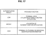
- the information processing apparatus 10-1 can also authorize the user to utilize different functions, depending on the authentication result after the combining by the authentication result combining unit 112. For example, the information processing apparatus 10-1 may authorize the user to utilize a function for using highly confidential information, as the authentication result after the combining is higher.
- FIG. 17 is a table that lists examples of provided functions for each authentication result, according to the third exemplary variant.
- the information processing apparatus 10-1 may authorize "terminal login” and "utilization of basic function application” for the user, when the authentication result after the combining is low, for example.
- the information processing apparatus 10-1 may further authorize "utilization of payment function application” for the user, when the authentication result after the combining is a middle level.
- the information processing apparatus 10-1 may further authorize "utilizing the information processing apparatus 10-1 as individual identification information (for example, like national ID)" for the user, when the authentication result after the combining is high. More specifically, in this case, the information processing apparatus 10-1 may change the status of the information processing apparatus 10-1 from "status that does not authorize presentation of individual identification information" to "status that authorizes presentation of individual identification information”.
- the information processing apparatus 10-1 may perform the authentication by using a plurality of types of biometric information.
- the information processing apparatus 10-1 may perform the authentication of the user by using the information (image) generated by combining two or more of the image of the iris, the image of the blood vessel pattern of the sclera, and the image of the retina.
- the information processing apparatus 10-1 may perform the authentication separately with regard to a plurality of types of biometric information.
- the information processing apparatus 10-1 can also identify which user the person of the image capturing target is, on the basis of the feature values of the eyes of all users recorded in the user information DB 128.
- the information processing apparatus 10-1 first performs the authentication by comparing each of the captured images of the eye of a plurality of sight line directions of the target person which are captured by the imaging unit 124, with the feature value of the same sight line direction as the captured image of the eye, among the feature values of the eyes of the respective users that belong to a specific group (or all users), which are recorded in the user information DB 128, respectively. Then, the information processing apparatus 10-1 can identify the user of the highest authentication result as the target person.
- the information processing apparatus 10-1 can identify who in the family the person of the image capturing target is, and can perform correct person authentication, even if the user ID is not input, for example.
- the information processing apparatus 10-1 may perform control such that the eye of the user is unable to be watched from a front surface side of the lens when the user inputs the PIN code.
- the information processing apparatus 10-1 may display a black screen only on the front surface of the lens, at the time of the above input.
- the information processing apparatus 10-1 may include an openable and closable lens cover on the front surface of the lens and automatically close the lens cover at the time of the above input.
- the information processing apparatus 10-1 may include a second camera directed toward the forward direction on the front surface of the lens, and the information processing apparatus 10-1 may perform control such that the eye of the user is unable to be watched from the front surface side of the lens, only when the above input is conducted and a person is detected in the forward direction of the user on the basis of the image captured by the second camera.
- the present embodiment can provide a computer program for causing hardware such as the CPU 150, the ROM 152, and the RAM 154 to provide a function equivalent to each configuration of the above information processing apparatus 10-1. Also, a recording medium in which the computer program is recorded is provided.
Claims (13)
- Appareil de traitement d'informations (10-1, 10-2) comprenant :une unité d'authentification d'informations biométriques (106) configurée pour authentifier des informations biométriques identifiées à partir de chacune d'une pluralité d'images capturées d'un œil d'un utilisateur sur la base d'une pluralité d'images de référence de l'œil de l'utilisateur correspondant à une pluralité de directions de ligne de visée différentes de l'œil de l'utilisateur et pour fournir un résultat d'authentification pour chacune des images capturées, la pluralité d'images capturées étant capturées pour différentes directions de ligne de visée de l'œil de l'utilisateur lorsque la direction de ligne de visée de l'œil de l'utilisateur change, où chaque image capturée correspond à une direction de ligne de visée différente de l'œil de l'utilisateur, et où l'unité d'authentification d'informations biométriques effectue l'authentification des informations biométriques en comparant chacune de la pluralité d'images capturées de l'œil avec une image de référence de l'œil de l'utilisateur qui a la même direction de ligne de visée que l'image capturée de l'œil ;une unité de combinaison de résultats d'authentification (112) configurée pour combiner une pluralité de résultats d'authentification fournis par l'unité d'authentification d'informations biométriques ;une unité d'identification de schéma de mouvement de ligne de visée (110) configurée pour identifier un schéma de mouvement de la ligne de visée de l'utilisateur sur la base de la pluralité d'images capturées de l'œil ; etune unité d'authentification de schéma de mouvement de ligne de visée (108) configurée pour authentifier la validité du schéma de mouvement identifié de la ligne de visée, sur la base d'un schéma de mouvement de ligne de visée enregistré qui est enregistré en association avec l'utilisateur, où l'unité de combinaison de résultats d'authentification combine les résultats d'authentification fournis par l'unité d'authentification d'informations biométriques et un résultat d'authentification fourni par l'unité d'authentification de schéma de mouvement de ligne de visée.
- Appareil de traitement d'informations selon la revendication 1, dans lequel :
l'unité d'identification de schéma de mouvement de ligne de visée identifie le schéma de mouvement de la ligne de visée de l'utilisateur sur la base des directions de ligne de visée identifiées à partir de la pluralité d'images capturées de l'œil. - Appareil de traitement d'informations selon la revendication 2, dans lequel :
l'unité d'identification de schéma de mouvement de ligne de visée identifie une séquence, suivant un ordre de capture d'images, des directions de ligne de visée identifiées à partir de la pluralité d'images capturées de l'œil, en tant que schéma de mouvement de la ligne de visée de l'utilisateur. - Appareil de traitement d'informations selon la revendication 1, dans lequel :
l'unité d'identification de schéma de mouvement de ligne de visée authentifie la validité du schéma de mouvement de la ligne de visée identifié par l'unité d'identification de schéma de mouvement de ligne de visée, sur la base du schéma de mouvement de ligne de visée enregistré, lequel est en outre enregistré en association avec un écran d'authentification affiché. - Appareil de traitement d'informations selon la revendication 1, dans lequel :
l'unité de combinaison de résultats d'authentification combine, par combinaison linéaire, les résultats d'authentification fournis par l'unité d'authentification d'informations biométriques et le résultat d'authentification fourni par l'unité d'authentification de motif de mouvement de ligne de visée. - Appareil de traitement d'informations selon la revendication 1, comprenant en outre :une unité de détermination de qualité d'image (114) configurée pour déterminer une qualité d'image d'une région imagée de l'œil par rapport à chacune de la pluralité d'images capturées de l'œil,où l'unité de combinaison de résultats d'authentification combine des résultats d'authentification autres qu'un résultat d'authentification correspondant à une image capturée qui est déterminée comme ayant une faible qualité d'image par l'unité de détermination de qualité d'image parmi une pluralité de résultats d'authentification par l'unité d'authentification d'informations biométriques.
- Appareil de traitement d'informations selon la revendication 1, comprenant en outre :une unité d'acquisition (120) configurée pour acquérir des informations d'identification de l'utilisateur,où l'unité d'authentification d'informations biométriques authentifie les informations biométriques identifiées à partir de chacune de la pluralité d'images capturées de l'œil, sur la base de la pluralité d'images de référence de l'œil qui sont enregistrées en association avec les informations d'identification acquises.
- Appareil de traitement d'informations selon la revendication 1, comprenant en outre :
une unité d'authentification d'utilisateur (116) configurée pour authentifier l'utilisateur en comparant un résultat combiné par l'unité de combinaison de résultats d'authentification et une valeur de seuil prédéterminée. - Appareil de traitement d'informations selon la revendication 1, comprenant en outre :
une unité d'affichage (122) configurée pour afficher un écran d'affichage. - Appareil de traitement d'informations selon la revendication 1, comprenant en outre :
une unité d'imagerie (124) configurée pour capturer une image de l'œil de l'utilisateur. - Appareil de traitement d'informations selon la revendication 9, dans lequel :
l'appareil de traitement d'informations est un dispositif porté sur la tête. - Procédé de traitement d'informations comprenant les étapes suivantes :authentifier des informations biométriques identifiées à partir de chacune d'une pluralité d'images capturées d'un œil d'un utilisateur sur la base d'une pluralité d'images de référence de l'œil de l'utilisateur correspondant à une pluralité de directions de ligne de visée différentes de l'œil de l'utilisateur et fournir un résultat d'authentification pour chacune des images capturées, la pluralité d'images capturées étant capturées pour différentes directions de ligne de visée de l'œil de l'utilisateur lorsque la direction de ligne de visée de l'œil de l'utilisateur change, où chaque image capturée correspond à une direction de ligne de visée différente de l'œil de l'utilisateur, et où l'authentification des informations biométriques comprend de comparer chacune de la pluralité d'images capturées de l'œil avec une image de référence de l'œil de l'utilisateur qui a la même direction de ligne de visée que l'image capturée de l'œil ;combiner une pluralité de résultats d'authentification des informations biométriques ;identifier un schéma de mouvement de la ligne de visée de l'utilisateur sur la base de la pluralité d'images capturées de l'œil ;authentifier la validité du schéma de mouvement identifié de la ligne de visée, sur la base d'un schéma de mouvement de ligne de visée enregistré en association avec l'utilisateur ; etcombiner la pluralité de résultats d'authentification des informations biométriques et un résultat d'authentification fourni par l'authentification de la validité du schéma de mouvement identifié de la ligne de visée.
- Programme permettant à un ordinateur de fonctionner comme :une unité d'authentification d'informations biométriques (106) configurée pour authentifier des informations biométriques identifiées à partir de chacune d'une pluralité d'images capturées d'un œil d'un utilisateur sur la base d'une pluralité d'images de référence de l'œil de l'utilisateur correspondant à une pluralité de directions de ligne de visée différentes de l'œil de l'utilisateur et pour fournir un résultat d'authentification pour chacune des images capturées, la pluralité d'images capturées étant capturées pour différentes directions de ligne de visée de l'œil de l'utilisateur lorsque la direction de ligne de visée de l'œil de l'utilisateur change, où chaque image capturée correspond à une direction de ligne de visée différente de l'œil de l'utilisateur, et où l'unité d'authentification d'informations biométriques effectue l'authentification des informations biométriques en comparant chacune de la pluralité d'images capturées de l'œil avec une image de référence de l'œil de l'utilisateur qui a la même direction de ligne de visée que l'image capturée de l'œil ;une unité de combinaison de résultats d'authentification (112) configurée pour combiner une pluralité de résultats d'authentification fournis par l'unité d'authentification d'informations biométriques ;une unité d'identification de schéma de mouvement de ligne de visée (110) configurée pour identifier un schéma de mouvement de la ligne de visée de l'utilisateur sur la base de la pluralité d'images capturées de l'œil ; etune unité d'authentification de schéma de mouvement de ligne de visée (108) configurée pour authentifier la validité du schéma de mouvement identifié de la ligne de visée, sur la base d'un schéma de mouvement de ligne de visée enregistré qui est enregistré en association avec l'utilisateur,où l'unité de combinaison de résultats d'authentification combine les résultats d'authentification fournis par l'unité d'authentification d'informations biométriques et un résultat d'authentification fourni par l'unité d'authentification de schéma de mouvement de ligne de visée.
Applications Claiming Priority (2)
| Application Number | Priority Date | Filing Date | Title |
|---|---|---|---|
| JP2014246521 | 2014-12-05 | ||
| PCT/JP2015/074080 WO2016088415A1 (fr) | 2014-12-05 | 2015-08-26 | Dispositif de traitement d'informations, procédé de traitement d'informations et programme |
Publications (3)
| Publication Number | Publication Date |
|---|---|
| EP3229205A1 EP3229205A1 (fr) | 2017-10-11 |
| EP3229205A4 EP3229205A4 (fr) | 2018-08-08 |
| EP3229205B1 true EP3229205B1 (fr) | 2021-10-13 |
Family
ID=56091373
Family Applications (1)
| Application Number | Title | Priority Date | Filing Date |
|---|---|---|---|
| EP15865190.1A Active EP3229205B1 (fr) | 2014-12-05 | 2015-08-26 | Dispositif de traitement d'informations, procédé de traitement d'informations et programme |
Country Status (4)
| Country | Link |
|---|---|
| US (1) | US10019563B2 (fr) |
| EP (1) | EP3229205B1 (fr) |
| JP (1) | JPWO2016088415A1 (fr) |
| WO (1) | WO2016088415A1 (fr) |
Families Citing this family (8)
| Publication number | Priority date | Publication date | Assignee | Title |
|---|---|---|---|---|
| KR102255351B1 (ko) * | 2014-09-11 | 2021-05-24 | 삼성전자주식회사 | 홍채 인식 방법 및 장치 |
| CA3011637A1 (fr) | 2016-01-19 | 2017-07-27 | Magic Leap, Inc. | Collecte, selection et combinaison d'images oculaires |
| KR102471916B1 (ko) * | 2016-06-03 | 2022-11-29 | 엘지전자 주식회사 | 모바일 디바이스 및 그 제어 방법 |
| IL248721A0 (en) * | 2016-11-03 | 2017-02-28 | Khoury Elias | An accessory for providing hands-free computer input |
| WO2020036238A1 (fr) * | 2018-08-16 | 2020-02-20 | 삼성전자(주) | Dispositif électronique et son procédé de fonctionnement |
| US20200089855A1 (en) * | 2018-09-19 | 2020-03-19 | XRSpace CO., LTD. | Method of Password Authentication by Eye Tracking in Virtual Reality System |
| US11087577B2 (en) * | 2018-12-14 | 2021-08-10 | Johnson Controls Tyco IP Holdings LLP | Systems and methods of secure pin code entry |
| US20240054194A1 (en) * | 2021-09-27 | 2024-02-15 | Nec Corporation | Authentication system, authentication apparatus, authentication method and recording medium |
Family Cites Families (17)
| Publication number | Priority date | Publication date | Assignee | Title |
|---|---|---|---|---|
| JP3991042B2 (ja) * | 2002-02-05 | 2007-10-17 | 松下電器産業株式会社 | 個人認証方法および個人認証装置 |
| KR100954640B1 (ko) | 2002-02-05 | 2010-04-27 | 파나소닉 주식회사 | 개인인증방법 및 개인인증장치 |
| US8705808B2 (en) * | 2003-09-05 | 2014-04-22 | Honeywell International Inc. | Combined face and iris recognition system |
| JP4765575B2 (ja) * | 2005-11-18 | 2011-09-07 | 富士通株式会社 | 個人認証方法、個人認証プログラムおよび個人認証装置 |
| JP2007159610A (ja) * | 2005-12-09 | 2007-06-28 | Matsushita Electric Ind Co Ltd | 登録装置、認証装置、登録認証装置、登録方法、認証方法、登録プログラムおよび認証プログラム |
| US7986816B1 (en) * | 2006-09-27 | 2011-07-26 | University Of Alaska | Methods and systems for multiple factor authentication using gaze tracking and iris scanning |
| JP5277365B2 (ja) | 2008-04-06 | 2013-08-28 | 国立大学法人九州工業大学 | 個人認証方法及びそれに使用する個人認証装置 |
| JP5387007B2 (ja) * | 2009-01-22 | 2014-01-15 | 日本電気株式会社 | 画像処理装置、生体認証装置、画像処理方法及びプログラム |
| JP5316017B2 (ja) * | 2009-01-22 | 2013-10-16 | 日本電気株式会社 | 画像処理装置、生体認証装置、画像処理方法及びプログラム |
| US8520903B2 (en) * | 2010-02-01 | 2013-08-27 | Daon Holdings Limited | Method and system of accounting for positional variability of biometric features |
| JP5548042B2 (ja) | 2010-06-23 | 2014-07-16 | ソフトバンクモバイル株式会社 | ユーザ端末装置及びショッピングシステム |
| US9020207B2 (en) * | 2011-06-07 | 2015-04-28 | Accenture Global Services Limited | Biometric authentication technology |
| CA2750287C (fr) * | 2011-08-29 | 2012-07-03 | Microsoft Corporation | Detection du regard dans un affichage transparent, pres de l'oeil et de realite mixte |
| US8369595B1 (en) * | 2012-08-10 | 2013-02-05 | EyeVerify LLC | Texture features for biometric authentication |
| US8953850B2 (en) * | 2012-08-15 | 2015-02-10 | International Business Machines Corporation | Ocular biometric authentication with system verification |
| JP2014092940A (ja) | 2012-11-02 | 2014-05-19 | Sony Corp | 画像表示装置及び画像表示方法、並びにコンピューター・プログラム |
| AU2015297035B2 (en) * | 2014-05-09 | 2018-06-28 | Google Llc | Systems and methods for biomechanically-based eye signals for interacting with real and virtual objects |
-
2015
- 2015-08-26 JP JP2016562326A patent/JPWO2016088415A1/ja active Pending
- 2015-08-26 EP EP15865190.1A patent/EP3229205B1/fr active Active
- 2015-08-26 US US15/529,744 patent/US10019563B2/en active Active
- 2015-08-26 WO PCT/JP2015/074080 patent/WO2016088415A1/fr active Application Filing
Non-Patent Citations (1)
| Title |
|---|
| None * |
Also Published As
| Publication number | Publication date |
|---|---|
| EP3229205A4 (fr) | 2018-08-08 |
| JPWO2016088415A1 (ja) | 2017-09-14 |
| WO2016088415A1 (fr) | 2016-06-09 |
| EP3229205A1 (fr) | 2017-10-11 |
| US20170308690A1 (en) | 2017-10-26 |
| US10019563B2 (en) | 2018-07-10 |
Similar Documents
| Publication | Publication Date | Title |
|---|---|---|
| EP3229205B1 (fr) | Dispositif de traitement d'informations, procédé de traitement d'informations et programme | |
| US9922238B2 (en) | Apparatuses, systems, and methods for confirming identity | |
| JP7004522B2 (ja) | ライブネス検査方法及び装置 | |
| Rattani et al. | ICIP 2016 competition on mobile ocular biometric recognition | |
| US10192109B2 (en) | Identification and/or authentication of a user using gaze information | |
| KR101415287B1 (ko) | 라이브니스 검출을 위한 방법, 컴퓨터 판독가능한 저장 디바이스 및 컴퓨팅 디바이스 | |
| US7986816B1 (en) | Methods and systems for multiple factor authentication using gaze tracking and iris scanning | |
| US9152850B2 (en) | Authentication apparatus, authentication method, and program | |
| EP2680192B1 (fr) | Reconnaissance faciale | |
| US20190332757A1 (en) | Method and apparatus for authenticating a user of a computing device | |
| EP2148303A1 (fr) | Système de gestion de configuration des veines, dispositif et procédé d'enregistrement de configuration des veines, dispositif et procédé d'authentification de configuration des veines, programme et structure de données des veines | |
| EP3440593B1 (fr) | Procédé et appareil pour reconnaissance d'iris | |
| EP2858299B1 (fr) | Dispositif et procédé d'authentification biométrique utilisant les veines | |
| EP2148295A1 (fr) | Système de gestion de configuration des veines, dispositif et procédé d'enregistrement de configuration des veines, dispositif et procédé d'authentification de configuration des veines, programme et structure de données des veines | |
| US20160188975A1 (en) | Biometric identification via retina scanning | |
| CN112639871A (zh) | 生物体认证系统、生物体认证方法及程序 | |
| Jiang et al. | Multilevel fusing paired visible light and near-infrared spectral images for face anti-spoofing | |
| EP2148302A1 (fr) | Système de gestion de configuration des veines, dispositif et procédé d'enregistrement de configuration des veines, dispositif et procédé d'authentification de configuration des veines, programme et structure de données des veines | |
| JP6150509B2 (ja) | 顔認証装置 | |
| US8320639B2 (en) | Vein pattern management system, vein pattern registration apparatus, vein pattern authentication apparatus, vein pattern registration method, vein pattern authentication method, program, and vein data configuration | |
| JP6150491B2 (ja) | 顔認証装置 | |
| US11195009B1 (en) | Infrared-based spoof detection | |
| EP3893147B1 (fr) | Détection de la vivacité à l'aide d'un dispositif comprenant une source d'éclairage | |
| CN115701307A (zh) | 评价方法、信息处理装置以及评价程序 |
Legal Events
| Date | Code | Title | Description |
|---|---|---|---|
| STAA | Information on the status of an ep patent application or granted ep patent |
Free format text: STATUS: THE INTERNATIONAL PUBLICATION HAS BEEN MADE |
|
| PUAI | Public reference made under article 153(3) epc to a published international application that has entered the european phase |
Free format text: ORIGINAL CODE: 0009012 |
|
| STAA | Information on the status of an ep patent application or granted ep patent |
Free format text: STATUS: REQUEST FOR EXAMINATION WAS MADE |
|
| 17P | Request for examination filed |
Effective date: 20170529 |
|
| AK | Designated contracting states |
Kind code of ref document: A1 Designated state(s): AL AT BE BG CH CY CZ DE DK EE ES FI FR GB GR HR HU IE IS IT LI LT LU LV MC MK MT NL NO PL PT RO RS SE SI SK SM TR |
|
| AX | Request for extension of the european patent |
Extension state: BA ME |
|
| DAV | Request for validation of the european patent (deleted) | ||
| DAX | Request for extension of the european patent (deleted) | ||
| A4 | Supplementary search report drawn up and despatched |
Effective date: 20180705 |
|
| RIC1 | Information provided on ipc code assigned before grant |
Ipc: G06K 9/62 20060101ALI20180629BHEP Ipc: G06F 3/01 20060101ALI20180629BHEP Ipc: G06K 9/00 20060101ALI20180629BHEP Ipc: G06T 7/00 20170101AFI20180629BHEP |
|
| STAA | Information on the status of an ep patent application or granted ep patent |
Free format text: STATUS: EXAMINATION IS IN PROGRESS |
|
| 17Q | First examination report despatched |
Effective date: 20190627 |
|
| STAA | Information on the status of an ep patent application or granted ep patent |
Free format text: STATUS: EXAMINATION IS IN PROGRESS |
|
| GRAP | Despatch of communication of intention to grant a patent |
Free format text: ORIGINAL CODE: EPIDOSNIGR1 |
|
| STAA | Information on the status of an ep patent application or granted ep patent |
Free format text: STATUS: GRANT OF PATENT IS INTENDED |
|
| INTG | Intention to grant announced |
Effective date: 20210511 |
|
| RAP3 | Party data changed (applicant data changed or rights of an application transferred) |
Owner name: SONY GROUP CORPORATION |
|
| GRAS | Grant fee paid |
Free format text: ORIGINAL CODE: EPIDOSNIGR3 |
|
| GRAA | (expected) grant |
Free format text: ORIGINAL CODE: 0009210 |
|
| STAA | Information on the status of an ep patent application or granted ep patent |
Free format text: STATUS: THE PATENT HAS BEEN GRANTED |
|
| AK | Designated contracting states |
Kind code of ref document: B1 Designated state(s): AL AT BE BG CH CY CZ DE DK EE ES FI FR GB GR HR HU IE IS IT LI LT LU LV MC MK MT NL NO PL PT RO RS SE SI SK SM TR |
|
| REG | Reference to a national code |
Ref country code: GB Ref legal event code: FG4D |
|
| REG | Reference to a national code |
Ref country code: CH Ref legal event code: EP |
|
| REG | Reference to a national code |
Ref country code: DE Ref legal event code: R096 Ref document number: 602015074168 Country of ref document: DE |
|
| REG | Reference to a national code |
Ref country code: IE Ref legal event code: FG4D |
|
| REG | Reference to a national code |
Ref country code: AT Ref legal event code: REF Ref document number: 1438735 Country of ref document: AT Kind code of ref document: T Effective date: 20211115 |
|
| REG | Reference to a national code |
Ref country code: LT Ref legal event code: MG9D |
|
| REG | Reference to a national code |
Ref country code: NL Ref legal event code: MP Effective date: 20211013 |
|
| REG | Reference to a national code |
Ref country code: AT Ref legal event code: MK05 Ref document number: 1438735 Country of ref document: AT Kind code of ref document: T Effective date: 20211013 |
|
| PG25 | Lapsed in a contracting state [announced via postgrant information from national office to epo] |
Ref country code: RS Free format text: LAPSE BECAUSE OF FAILURE TO SUBMIT A TRANSLATION OF THE DESCRIPTION OR TO PAY THE FEE WITHIN THE PRESCRIBED TIME-LIMIT Effective date: 20211013 Ref country code: LT Free format text: LAPSE BECAUSE OF FAILURE TO SUBMIT A TRANSLATION OF THE DESCRIPTION OR TO PAY THE FEE WITHIN THE PRESCRIBED TIME-LIMIT Effective date: 20211013 Ref country code: FI Free format text: LAPSE BECAUSE OF FAILURE TO SUBMIT A TRANSLATION OF THE DESCRIPTION OR TO PAY THE FEE WITHIN THE PRESCRIBED TIME-LIMIT Effective date: 20211013 Ref country code: BG Free format text: LAPSE BECAUSE OF FAILURE TO SUBMIT A TRANSLATION OF THE DESCRIPTION OR TO PAY THE FEE WITHIN THE PRESCRIBED TIME-LIMIT Effective date: 20220113 Ref country code: AT Free format text: LAPSE BECAUSE OF FAILURE TO SUBMIT A TRANSLATION OF THE DESCRIPTION OR TO PAY THE FEE WITHIN THE PRESCRIBED TIME-LIMIT Effective date: 20211013 |
|
| PG25 | Lapsed in a contracting state [announced via postgrant information from national office to epo] |
Ref country code: IS Free format text: LAPSE BECAUSE OF FAILURE TO SUBMIT A TRANSLATION OF THE DESCRIPTION OR TO PAY THE FEE WITHIN THE PRESCRIBED TIME-LIMIT Effective date: 20220213 Ref country code: SE Free format text: LAPSE BECAUSE OF FAILURE TO SUBMIT A TRANSLATION OF THE DESCRIPTION OR TO PAY THE FEE WITHIN THE PRESCRIBED TIME-LIMIT Effective date: 20211013 Ref country code: PT Free format text: LAPSE BECAUSE OF FAILURE TO SUBMIT A TRANSLATION OF THE DESCRIPTION OR TO PAY THE FEE WITHIN THE PRESCRIBED TIME-LIMIT Effective date: 20220214 Ref country code: PL Free format text: LAPSE BECAUSE OF FAILURE TO SUBMIT A TRANSLATION OF THE DESCRIPTION OR TO PAY THE FEE WITHIN THE PRESCRIBED TIME-LIMIT Effective date: 20211013 Ref country code: NO Free format text: LAPSE BECAUSE OF FAILURE TO SUBMIT A TRANSLATION OF THE DESCRIPTION OR TO PAY THE FEE WITHIN THE PRESCRIBED TIME-LIMIT Effective date: 20220113 Ref country code: NL Free format text: LAPSE BECAUSE OF FAILURE TO SUBMIT A TRANSLATION OF THE DESCRIPTION OR TO PAY THE FEE WITHIN THE PRESCRIBED TIME-LIMIT Effective date: 20211013 Ref country code: LV Free format text: LAPSE BECAUSE OF FAILURE TO SUBMIT A TRANSLATION OF THE DESCRIPTION OR TO PAY THE FEE WITHIN THE PRESCRIBED TIME-LIMIT Effective date: 20211013 Ref country code: HR Free format text: LAPSE BECAUSE OF FAILURE TO SUBMIT A TRANSLATION OF THE DESCRIPTION OR TO PAY THE FEE WITHIN THE PRESCRIBED TIME-LIMIT Effective date: 20211013 Ref country code: GR Free format text: LAPSE BECAUSE OF FAILURE TO SUBMIT A TRANSLATION OF THE DESCRIPTION OR TO PAY THE FEE WITHIN THE PRESCRIBED TIME-LIMIT Effective date: 20220114 Ref country code: ES Free format text: LAPSE BECAUSE OF FAILURE TO SUBMIT A TRANSLATION OF THE DESCRIPTION OR TO PAY THE FEE WITHIN THE PRESCRIBED TIME-LIMIT Effective date: 20211013 |
|
| REG | Reference to a national code |
Ref country code: DE Ref legal event code: R097 Ref document number: 602015074168 Country of ref document: DE |
|
| PG25 | Lapsed in a contracting state [announced via postgrant information from national office to epo] |
Ref country code: SM Free format text: LAPSE BECAUSE OF FAILURE TO SUBMIT A TRANSLATION OF THE DESCRIPTION OR TO PAY THE FEE WITHIN THE PRESCRIBED TIME-LIMIT Effective date: 20211013 Ref country code: SK Free format text: LAPSE BECAUSE OF FAILURE TO SUBMIT A TRANSLATION OF THE DESCRIPTION OR TO PAY THE FEE WITHIN THE PRESCRIBED TIME-LIMIT Effective date: 20211013 Ref country code: RO Free format text: LAPSE BECAUSE OF FAILURE TO SUBMIT A TRANSLATION OF THE DESCRIPTION OR TO PAY THE FEE WITHIN THE PRESCRIBED TIME-LIMIT Effective date: 20211013 Ref country code: EE Free format text: LAPSE BECAUSE OF FAILURE TO SUBMIT A TRANSLATION OF THE DESCRIPTION OR TO PAY THE FEE WITHIN THE PRESCRIBED TIME-LIMIT Effective date: 20211013 Ref country code: DK Free format text: LAPSE BECAUSE OF FAILURE TO SUBMIT A TRANSLATION OF THE DESCRIPTION OR TO PAY THE FEE WITHIN THE PRESCRIBED TIME-LIMIT Effective date: 20211013 Ref country code: CZ Free format text: LAPSE BECAUSE OF FAILURE TO SUBMIT A TRANSLATION OF THE DESCRIPTION OR TO PAY THE FEE WITHIN THE PRESCRIBED TIME-LIMIT Effective date: 20211013 |
|
| PLBE | No opposition filed within time limit |
Free format text: ORIGINAL CODE: 0009261 |
|
| STAA | Information on the status of an ep patent application or granted ep patent |
Free format text: STATUS: NO OPPOSITION FILED WITHIN TIME LIMIT |
|
| 26N | No opposition filed |
Effective date: 20220714 |
|
| PG25 | Lapsed in a contracting state [announced via postgrant information from national office to epo] |
Ref country code: AL Free format text: LAPSE BECAUSE OF FAILURE TO SUBMIT A TRANSLATION OF THE DESCRIPTION OR TO PAY THE FEE WITHIN THE PRESCRIBED TIME-LIMIT Effective date: 20211013 |
|
| PG25 | Lapsed in a contracting state [announced via postgrant information from national office to epo] |
Ref country code: SI Free format text: LAPSE BECAUSE OF FAILURE TO SUBMIT A TRANSLATION OF THE DESCRIPTION OR TO PAY THE FEE WITHIN THE PRESCRIBED TIME-LIMIT Effective date: 20211013 |
|
| PG25 | Lapsed in a contracting state [announced via postgrant information from national office to epo] |
Ref country code: MC Free format text: LAPSE BECAUSE OF FAILURE TO SUBMIT A TRANSLATION OF THE DESCRIPTION OR TO PAY THE FEE WITHIN THE PRESCRIBED TIME-LIMIT Effective date: 20211013 |
|
| REG | Reference to a national code |
Ref country code: CH Ref legal event code: PL |
|
| PG25 | Lapsed in a contracting state [announced via postgrant information from national office to epo] |
Ref country code: LU Free format text: LAPSE BECAUSE OF NON-PAYMENT OF DUE FEES Effective date: 20220826 Ref country code: LI Free format text: LAPSE BECAUSE OF NON-PAYMENT OF DUE FEES Effective date: 20220831 Ref country code: CH Free format text: LAPSE BECAUSE OF NON-PAYMENT OF DUE FEES Effective date: 20220831 |
|
| REG | Reference to a national code |
Ref country code: BE Ref legal event code: MM Effective date: 20220831 |
|
| PG25 | Lapsed in a contracting state [announced via postgrant information from national office to epo] |
Ref country code: IT Free format text: LAPSE BECAUSE OF FAILURE TO SUBMIT A TRANSLATION OF THE DESCRIPTION OR TO PAY THE FEE WITHIN THE PRESCRIBED TIME-LIMIT Effective date: 20211013 |
|
| P01 | Opt-out of the competence of the unified patent court (upc) registered |
Effective date: 20230527 |
|
| PG25 | Lapsed in a contracting state [announced via postgrant information from national office to epo] |
Ref country code: IE Free format text: LAPSE BECAUSE OF NON-PAYMENT OF DUE FEES Effective date: 20220826 |
|
| PG25 | Lapsed in a contracting state [announced via postgrant information from national office to epo] |
Ref country code: BE Free format text: LAPSE BECAUSE OF NON-PAYMENT OF DUE FEES Effective date: 20220831 |
|
| PGFP | Annual fee paid to national office [announced via postgrant information from national office to epo] |
Ref country code: GB Payment date: 20230720 Year of fee payment: 9 |
|
| PGFP | Annual fee paid to national office [announced via postgrant information from national office to epo] |
Ref country code: FR Payment date: 20230720 Year of fee payment: 9 Ref country code: DE Payment date: 20230720 Year of fee payment: 9 |
|
| PG25 | Lapsed in a contracting state [announced via postgrant information from national office to epo] |
Ref country code: HU Free format text: LAPSE BECAUSE OF FAILURE TO SUBMIT A TRANSLATION OF THE DESCRIPTION OR TO PAY THE FEE WITHIN THE PRESCRIBED TIME-LIMIT; INVALID AB INITIO Effective date: 20150826 |
|
| PG25 | Lapsed in a contracting state [announced via postgrant information from national office to epo] |
Ref country code: CY Free format text: LAPSE BECAUSE OF FAILURE TO SUBMIT A TRANSLATION OF THE DESCRIPTION OR TO PAY THE FEE WITHIN THE PRESCRIBED TIME-LIMIT Effective date: 20211013 |