EP3229092A1 - Verfahren zur bereitstellung von einer überwachungsoberfläche - Google Patents
Verfahren zur bereitstellung von einer überwachungsoberfläche Download PDFInfo
- Publication number
- EP3229092A1 EP3229092A1 EP16198590.8A EP16198590A EP3229092A1 EP 3229092 A1 EP3229092 A1 EP 3229092A1 EP 16198590 A EP16198590 A EP 16198590A EP 3229092 A1 EP3229092 A1 EP 3229092A1
- Authority
- EP
- European Patent Office
- Prior art keywords
- user
- monitoring screen
- objects
- information
- display unit
- Prior art date
- Legal status (The legal status is an assumption and is not a legal conclusion. Google has not performed a legal analysis and makes no representation as to the accuracy of the status listed.)
- Ceased
Links
Images



Classifications
-
- G—PHYSICS
- G05—CONTROLLING; REGULATING
- G05B—CONTROL OR REGULATING SYSTEMS IN GENERAL; FUNCTIONAL ELEMENTS OF SUCH SYSTEMS; MONITORING OR TESTING ARRANGEMENTS FOR SUCH SYSTEMS OR ELEMENTS
- G05B19/00—Program-control systems
- G05B19/02—Program-control systems electric
-
- G—PHYSICS
- G06—COMPUTING OR CALCULATING; COUNTING
- G06F—ELECTRIC DIGITAL DATA PROCESSING
- G06F3/00—Input arrangements for transferring data to be processed into a form capable of being handled by the computer; Output arrangements for transferring data from processing unit to output unit, e.g. interface arrangements
- G06F3/14—Digital output to display device ; Cooperation and interconnection of the display device with other functional units
-
- G—PHYSICS
- G05—CONTROLLING; REGULATING
- G05B—CONTROL OR REGULATING SYSTEMS IN GENERAL; FUNCTIONAL ELEMENTS OF SUCH SYSTEMS; MONITORING OR TESTING ARRANGEMENTS FOR SUCH SYSTEMS OR ELEMENTS
- G05B23/00—Testing or monitoring of control systems or parts thereof
- G05B23/02—Electric testing or monitoring
-
- G—PHYSICS
- G05—CONTROLLING; REGULATING
- G05B—CONTROL OR REGULATING SYSTEMS IN GENERAL; FUNCTIONAL ELEMENTS OF SUCH SYSTEMS; MONITORING OR TESTING ARRANGEMENTS FOR SUCH SYSTEMS OR ELEMENTS
- G05B23/00—Testing or monitoring of control systems or parts thereof
- G05B23/02—Electric testing or monitoring
- G05B23/0205—Electric testing or monitoring by means of a monitoring system capable of detecting and responding to faults
- G05B23/0208—Electric testing or monitoring by means of a monitoring system capable of detecting and responding to faults characterized by the configuration of the monitoring system
- G05B23/0216—Human interface functionality, e.g. monitoring system providing help to the user in the selection of tests or in its configuration
-
- G—PHYSICS
- G06—COMPUTING OR CALCULATING; COUNTING
- G06F—ELECTRIC DIGITAL DATA PROCESSING
- G06F16/00—Information retrieval; Database structures therefor; File system structures therefor
- G06F16/20—Information retrieval; Database structures therefor; File system structures therefor of structured data, e.g. relational data
- G06F16/28—Databases characterised by their database models, e.g. relational or object models
- G06F16/284—Relational databases
- G06F16/288—Entity relationship models
-
- G—PHYSICS
- G06—COMPUTING OR CALCULATING; COUNTING
- G06F—ELECTRIC DIGITAL DATA PROCESSING
- G06F3/00—Input arrangements for transferring data to be processed into a form capable of being handled by the computer; Output arrangements for transferring data from processing unit to output unit, e.g. interface arrangements
- G06F3/01—Input arrangements or combined input and output arrangements for interaction between user and computer
- G06F3/048—Interaction techniques based on graphical user interfaces [GUI]
- G06F3/0481—Interaction techniques based on graphical user interfaces [GUI] based on specific properties of the displayed interaction object or a metaphor-based environment, e.g. interaction with desktop elements like windows or icons, or assisted by a cursor's changing behaviour or appearance
- G06F3/0482—Interaction with lists of selectable items, e.g. menus
-
- G—PHYSICS
- G06—COMPUTING OR CALCULATING; COUNTING
- G06F—ELECTRIC DIGITAL DATA PROCESSING
- G06F40/00—Handling natural language data
- G06F40/10—Text processing
- G06F40/166—Editing, e.g. inserting or deleting
- G06F40/186—Templates
-
- G—PHYSICS
- G05—CONTROLLING; REGULATING
- G05B—CONTROL OR REGULATING SYSTEMS IN GENERAL; FUNCTIONAL ELEMENTS OF SUCH SYSTEMS; MONITORING OR TESTING ARRANGEMENTS FOR SUCH SYSTEMS OR ELEMENTS
- G05B2219/00—Program-control systems
- G05B2219/20—Pc systems
- G05B2219/24—Pc safety
- G05B2219/24215—Scada supervisory control and data acquisition
Definitions
- the present disclosure relates to a method of providing monitoring screen composition functions, and more particularly, a method of providing monitoring screen composition functions for controls of systems such as a SCADA, a DCS, an EMS, a DMS and a MG.
- a user uses a monitoring screen displayed through a terminal device such as a computer.
- the user monitors data, which is indicated by facilities installed in the field, through the monitoring screen and gives control commands as necessary.
- Such a monitoring screen is typically composed by the user through, e.g., a graphic editor.
- the user uses the graphic editor to arrange objects or figures, which correspond to the facilities installed on the field, on an empty screen. Then, the user has to couple the objects into consideration of actual coupling relationships between the facilities and associate data with each of the objects.
- a generator and a breaker are represented as objects and, at a power distribution phase, a special facility such as a D/L is represented as an object.
- the user has to arrange all of the objects all over again and establish their coupling relationships and data manually one by one whenever the monitoring screen corresponding to each system is composed.
- the existing graphic editor has problems in that it takes much time for a user to compose a monitoring screen and that the user has to unnecessarily repeat the performance of the same tasks.
- a method of providing monitoring screen composition functions for controls of a system includes receiving a type of a monitoring screen to be created; receiving characteristics of the monitoring screen from the user; obtaining initial generation information corresponding to the type and the characteristics received from the user; and outputting an initial monitoring screen on a display unit based on the initial generation information.
- the present disclosure as described above may advantageously facilitate more quickly and easily composing a monitoring screen for controls of systems such as a SCADA, a DCS, an EMS and a MG.
- FIG. 1 is a block diagram illustrating a system configuration according to an embodiment of the present disclosure
- FIG. 2 is a flowchart of a method of providing monitoring screen composition functions according to an embodiment of the present disclosure.
- a method of providing monitoring screen composition functions according to an embodiment of the present disclosure will be described in detail with reference to FIGS. 1 and 2 .
- a user monitors data or state information of field facilities, which is collected by a system 12, through a monitoring screen displayed on a display unit of a user's terminal 14. Further, the user gives control commands on each of the facilities through the system 12 as necessary.
- the system 12 collects the data or state information of the facilities installed on the field and delivers the user's control commands on each of the facilities. Examples of the system 12 may include a SCADA system, a DCS system, an EMS system, a MG system and so on, but are not limited thereto.
- the system 12 may receive designated data or state information in real-time from the facilities installed on the field, and may store the received data or state information on a real-time DB 16.
- the system 12 may transmit the data or state information stored on the real-time DB 16 to the user's terminal 14 pursuant to a user's request.
- the present disclosure relates to a method of providing functions which facilitate a user to more quickly and easily compose a monitoring screen suitable for the system 12 through the user's terminal 14 in an environment of the described-above configuration.
- the user's terminal 14 first receives the type of a desired monitoring screen to be created from a user (202). For example, the user's terminal 14 may provide the user with a list of types of the monitoring screens such as a single line diagram, a tabular and an OCS (OLE Control eXtension) through the display unit. The user may choose the type of the desired monitoring screen, e.g., the single line diagram, from the list displayed on the display unit.
- OCS OCS
- the single line diagram herein means a screen on which the facilities installed on the field are displayed using various figures.
- each of the facilities installed on the field is displayed as an object and the coupling or linking relationships between the facilities are represented by, e.g., lines coupling the objects.
- data e.g., temperature, current, etc.
- state information indicated by each of the facilities may be indicated therein together with the objects.
- the tabular herein means a screen on which data or state information indicated by the facilities installed on the field is indicated in a form of table. On the tabular screen, each of the facilities is displayed based on certain criteria (e.g., name, installation place and the like). The data or state information indicated by each of the facilities is further displayed on the tabular screen together with a name of each of the facilities.
- An OCX screen herein means a monitoring screen configured by invoking components which have been previously generated.
- the OCX screen is implemented by an Object Linking and Embedding (OLE) function.
- OLE means a technology to allow linking and embedding subject files and programs.
- the OLE may refer to embedding diagrams into a Microsoft Word in use or embedding documents employing special template functions into a Microsoft Word in use.
- Controlling OLE functions may allow necessary information to be obtained and various resources to be shared with other programs.
- the present disclosure may generate to store functions required to compose a monitoring screen in a form of components and may invoke the stored components to generate the OCX screen.
- the user's terminal 14 receives characteristics of the monitoring screen to be created from a user (204).
- the characteristics of the monitoring screen may be determined according to a variety of criteria.
- the user's terminal 14 may provide the user with the type of the system 12, i.e., SCADA, DCS, EMS, MG, etc., as a list of characteristics.
- the user's terminal 14 may provide the user with a list of places or regions, i.e., stations, which each of the system is installed on/in. Then, the user may enter the characteristics of the monitoring screen in an order of, e.g., SCADA (the type of the system) - subway (place) - Seoul (region), through the list provided by the user's terminal 14.
- SCADA the type of the system
- place place
- Seoul Seoul
- the user's terminal 14 When the type and the characteristics of the monitoring screen are entered by the user, the user's terminal 14 obtains an initial generation information corresponding to the type and the characteristics entered by the user (206).
- the initial generation information corresponding to the type and the characteristics of the monitoring screen may be stored on an internal or external storage (not shown) of the user's terminal 14.
- the user's terminal 14 may obtain the initial generation information from the storage based on the type and the characteristics entered by the user.
- the initial generation information may contain one or more object information corresponding to the type and the characteristics of the monitoring screen, link information between objects, and object data information assigned to each of the objects.
- the object herein means the facilities, which are installed on the field, represented by figures or symbols.
- the link information is information indicating the coupling relationships between the objects and may be represented by figures and symbols coupling the objects.
- the object data information indicates data (e.g., temperature or current) or state information (e.g., the openings and/or the closings of the objects) indicated by the respective facilities.
- Step 208 of outputting the monitoring screen includes displaying one or more objects on the display unit based on the object information; representing the coupling relationships between the objects based on the link information; and indicating object data corresponding to each of the objects based on the object data information.
- Step 208 of outputting the monitoring screen includes generating predefined ports on links between the objects based on the link information contained in the initial generation information. Further, according to an embodiment of the present disclosure, Step 208 of outputting the monitoring screen includes generating ports other than the predefined ports on the links between the objects based on the link information contained in the initial generation information.
- the type or the characteristics of the monitoring screen which the user intends to generate may be stored in a form of files.
- the user may previously choose and store the type or the characteristics of the monitoring screen which the user intends to generate.
- the user's terminal 14 may automatically designate the type or the characteristics of the monitoring screen by loading thus stored file.
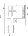
- FIGS. 3 and 4 are exemplary views of screen configurations of a monitoring screen composition tool displayed on the user's terminal according to an embodiment of the present disclosure.
- the user's terminal 14 may provide the user with a monitoring screen composition guide screen as shown in FIG. 3 through the display unit.
- the monitoring screen composition guide screen includes a menu of templates 31, a menu of user defined templates 32, and a menu of template wizard 33.
- the user's terminal 14 provides the user with templates 302, 303, 304, 305 and 306 which have been previously stored.
- the user's terminal 14 may display the previously stored templates 302, 303, 304, 305 and 306 in a state where the previously stored templates 302, 303, 304, 305 and 306 are respectively arranged according to the number of times chosen by the user.
- the user's terminal 14 may display the previously stored templates 302, 303, 304, 305 and 306 in a state where the previously stored templates 302, 303, 304, 305 and 306 are respectively arranged in order of time chosen by the user.
- a monitoring screen corresponding to the chosen template is outputted on the display unit. Thereafter, the user may modify the monitoring screen displayed on the display unit as desired. Moreover, the user may choose an empty screen 301 to compose a monitoring screen all over again.
- the user's terminal 14 When the menu of user defined templates 32 is chosen, the user's terminal 14 provides a list of templates, which the user formerly composed and has stored as a user defined template, on the display unit.
- a screen as shown in FIG. 4 is displayed on the display unit.
- a menu of basic screen 401, a menu of themes 402, a menu of screen splits 403, a menu of screen type definitions 404, a menu of screen characteristics definitions 405 and so on are displayed.
- the user's terminal 14 displays on the display unit an entering window or a list window in which the user can directly enter elementary items necessary for a monitoring screen configuration, e.g., a screen resolution, a title, an aspect ratio, etc.
- the user's terminal 14 displays on the display unit an entering window or a list window in which the user can designate visual elements for configuring the monitoring screen, e.g., a wallpaper, a font, an object color, etc.
- the user's terminal 14 displays on the display unit a list of layouts 411 to 414 illustrating the splits of a monitoring screen composition screen.
- the user's terminal 14 displays on the display unit a list of the types of the monitoring screen which the user intends to compose, e.g., a single line diagram, a tabular, or an OXC.
- the user's terminal 14 displays on the display unit an entering window or a choice window with respect to the characteristics of the monitoring screen which the user intends to compose.
- the user's terminal 14 may provide the user with the type of the system 12, i.e., SCADA, DCS, EMS, MG, etc., as a list of characteristics.
- the user's terminal 14 may provide the user with a list of places or regions, i.e., stations, which each of the system is installed on/in. Then, the user may enter the characteristics of the monitoring screen in an order of, e.g., SCADA (the type of the system) - subway (place) - Seoul (region), through the list provided by the user's terminal 14.
- SCADA the type of the system
- place place
- Seoul Seoul
- the user who has designated the items with respect to the monitoring screen which the user intends to compose through the template wizard may press a create button 422 to start a monitoring screen composition.
- the user's terminal 14 outputs on the display unit the monitoring composition screen on which items designated by the user are reflected.
- the user's terminal 14 may output an initial monitoring screen on the display unit based on the initial generation information corresponding to the type and the characteristics designated by the user as described above.
- the user's terminal 14 may store a monitoring screen, which the items designated by the user are reflected on, in the template name entered by the user.
- stored template may be thereafter provided to the user as a user defined template.
- FIG. 5 is an embodiment of the initial monitoring screen outputted on a display unit based on the initial generation information.
- the user's terminal 14 may output the initial monitoring screen (single line diagram) on the display unit as shown in FIG. 5 based on the initial generation information corresponding to the type and the characteristics designated by the user. That is, the user's terminal 14 may display objects 6171, 6172 and 6133 on the display unit as shown in FIG. 5 based on the object information contained in the initial generation information. Further, the user's terminal 14 may represent the coupling relationships among the objects 6171, 6172 and 6133 by solid lines as shown in FIG. 5 based on the link information contained the initial generation information. At this time, if the object 6133 is coupled between the objects 6171 and 6172 as shown in FIG. 5 , the user's terminal 14 may automatically generate and display a port 508.
- the initial monitoring screen single line diagram
- the user's terminal 14 may display object data 502, 504 and 506 respectively assigned to the objects 6171, 6172 and 6133 on the display unit as shown in FIG. 5 based on the object data information contained in the initial generation information.
- the object data 502, 504 and 506 may indicate data (e.g., temperature or current) or state information (e.g., the openings and/or closings of the objects) indicated by each of the objects.
- the user's terminal 14 may associate real-time DB information with each of the object data 502, 504 and 506 with reference to the object data information, the real-time DB information containing the object data 502, 504 and 506.
- the user's terminal 14 may associate a specific address in the real-time DB 16 or a real-time DB file stored on the real-time DB 16 with each of the object data 502, 504 and 506. Accordingly, each of the object data 502, 504 and 506 may reflect actual data in real time with reference to the specific address or file of the associated real-time DB 16.
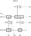
- FIG. 6 is another embodiment of the initial monitoring screen outputted on the display unit based on the initial generation information.
- the user's terminal 14 may output the initial monitoring screen (single line diagram) on the display unit as shown in FIG. 6 based on the initial generation information corresponding to the type and the characteristics designated by the user. That is, the user's terminal 14 may display objects 621, 6133, 6232, BSB_154_1 and BSB_154_2 on the display unit as shown in FIG. 6 based on the object information contained in the initial generation information. Further, the user's terminal 14 may represent the coupling relationships among the objects 621, 6133, 6232, BSB_154_1 and BSB_154_2 by solid lines as shown in FIG. 6 based on the link information contained the initial generation information.
- the user's terminal 14 may automatically generate and display ports 612, 614, 616 and 618 on linking points between the objects as shown in FIG. 6 .
- the user's terminal 14 may generate ports 616 and 618 other than predefined ports 612 and 614 on the links between the objects as shown in FIG. 6 with reference to the link information.
- the object BSB_154_1 has essentially only one defined port 612 and the object 612 and the object 6232 should be physically coupled to the port 612. Nonetheless, in order to more clearly represent the coupling relationship between the object 621 and the object 6232, the user's terminal 14 may generate to display the port 616 other than the predefined port 612 on the display unit as shown in FIG. 6 . Accordingly, the user may advantageously apprehend more clearly each coupling relationship between the objects.
- the user's terminal 14 may display object data 602, 604 and 606 respectively assigned to the objects 621, 6133 and 6232 on the display unit as shown in FIG. 6 based on the object data information contained in the initial generation information.
- the object data 602, 604 and 606 may indicate data (e.g., temperature or current) or state information (e.g., the openings and/or closings of the objects) indicated by each of the objects.
- the user's terminal 14 may associate real-time DB information with each of the object data 602, 604 and 606 with reference to the object data information, the real-time DB information containing the object data 602, 604 and 606.
- the user's terminal 14 may associate a specific address in the real-time DB 16 or a real-time DB file stored on the real-time DB 16 with each of the object data 602, 604 and 606. Accordingly, each of the object data 602, 604 and 606 may reflect actual data in real time with reference to the specific address or file of the associated real-time DB 16.
Landscapes
- Engineering & Computer Science (AREA)
- Theoretical Computer Science (AREA)
- Physics & Mathematics (AREA)
- General Physics & Mathematics (AREA)
- General Engineering & Computer Science (AREA)
- Databases & Information Systems (AREA)
- Human Computer Interaction (AREA)
- Automation & Control Theory (AREA)
- Data Mining & Analysis (AREA)
- Health & Medical Sciences (AREA)
- Artificial Intelligence (AREA)
- Audiology, Speech & Language Pathology (AREA)
- Computational Linguistics (AREA)
- General Health & Medical Sciences (AREA)
- User Interface Of Digital Computer (AREA)
- Controls And Circuits For Display Device (AREA)
Applications Claiming Priority (1)
| Application Number | Priority Date | Filing Date | Title |
|---|---|---|---|
| KR1020160040984A KR101888739B1 (ko) | 2016-04-04 | 2016-04-04 | 모니터링 화면 제작 기능 제공 방법 |
Publications (1)
| Publication Number | Publication Date |
|---|---|
| EP3229092A1 true EP3229092A1 (de) | 2017-10-11 |
Family
ID=57396266
Family Applications (1)
| Application Number | Title | Priority Date | Filing Date |
|---|---|---|---|
| EP16198590.8A Ceased EP3229092A1 (de) | 2016-04-04 | 2016-11-14 | Verfahren zur bereitstellung von einer überwachungsoberfläche |
Country Status (4)
| Country | Link |
|---|---|
| US (1) | US20170285891A1 (de) |
| EP (1) | EP3229092A1 (de) |
| KR (1) | KR101888739B1 (de) |
| CN (1) | CN107273073A (de) |
Families Citing this family (1)
| Publication number | Priority date | Publication date | Assignee | Title |
|---|---|---|---|---|
| KR101949727B1 (ko) * | 2018-07-02 | 2019-02-19 | 한화시스템 주식회사 | 객체간 링크 생성 시스템 및 이의 동작 방법 |
Citations (3)
| Publication number | Priority date | Publication date | Assignee | Title |
|---|---|---|---|---|
| US20070093916A1 (en) * | 2005-09-30 | 2007-04-26 | Microsoft Corporation | Template based management system |
| US20090164933A1 (en) * | 2007-12-21 | 2009-06-25 | Alan Richard Pederson | Methods and apparatus to present recipe progress status information |
| US20150220076A1 (en) * | 2012-10-25 | 2015-08-06 | Mitsubishi Electric Corporation | System construction support tool and system |
Family Cites Families (12)
| Publication number | Priority date | Publication date | Assignee | Title |
|---|---|---|---|---|
| JP2001075633A (ja) * | 1999-08-31 | 2001-03-23 | Fuji Electric Co Ltd | 施設内設備の管理画面表示装置 |
| US6925385B2 (en) * | 2003-05-16 | 2005-08-02 | Seawest Holdings, Inc. | Wind power management system and method |
| CN100351787C (zh) * | 2004-11-05 | 2007-11-28 | 中兴通讯股份有限公司 | 监控系统中组态监控页面生成方法 |
| JP4573844B2 (ja) * | 2007-01-19 | 2010-11-04 | 中国電力株式会社 | 監視制御装置用画面保守支援装置および監視制御装置の画面保守方法 |
| EP1965301A1 (de) * | 2007-02-27 | 2008-09-03 | Abb Research Ltd. | Verfahren und System zur Erzeugung einer Benutzeroberfläche eines Kontrollsystems |
| US8739030B2 (en) * | 2010-03-10 | 2014-05-27 | Salesforce.Com, Inc. | Providing a quote template in a multi-tenant database system environment |
| US9201558B1 (en) * | 2011-11-03 | 2015-12-01 | Pervasive Software Inc. | Data transformation system, graphical mapping tool, and method for creating a schema map |
| JP5752092B2 (ja) * | 2012-07-31 | 2015-07-22 | 三菱電機株式会社 | プログラマブル表示器 |
| US9547291B2 (en) * | 2013-10-14 | 2017-01-17 | Ivensys Systems, Inc. | Human machine interface (HMI) system having a symbol wizard creator |
| CN104361151B (zh) * | 2014-06-27 | 2017-08-29 | 许继电气股份有限公司 | 基于样式的变电站图形生成方法 |
| CN204256466U (zh) * | 2014-11-28 | 2015-04-08 | 上海泰清节能科技有限公司 | 热泵设备自动化控制系统 |
| US20170115645A1 (en) * | 2015-10-23 | 2017-04-27 | Ge Intelligent Platforms, Inc. | Apparatus and method for interfacing with supervisory monitoring and control arrangements |
-
2016
- 2016-04-04 KR KR1020160040984A patent/KR101888739B1/ko active Active
- 2016-11-14 EP EP16198590.8A patent/EP3229092A1/de not_active Ceased
- 2016-11-17 CN CN201611010999.3A patent/CN107273073A/zh active Pending
- 2016-11-18 US US15/356,037 patent/US20170285891A1/en not_active Abandoned
Patent Citations (3)
| Publication number | Priority date | Publication date | Assignee | Title |
|---|---|---|---|---|
| US20070093916A1 (en) * | 2005-09-30 | 2007-04-26 | Microsoft Corporation | Template based management system |
| US20090164933A1 (en) * | 2007-12-21 | 2009-06-25 | Alan Richard Pederson | Methods and apparatus to present recipe progress status information |
| US20150220076A1 (en) * | 2012-10-25 | 2015-08-06 | Mitsubishi Electric Corporation | System construction support tool and system |
Also Published As
| Publication number | Publication date |
|---|---|
| KR101888739B1 (ko) | 2018-08-14 |
| US20170285891A1 (en) | 2017-10-05 |
| KR20170114362A (ko) | 2017-10-16 |
| CN107273073A (zh) | 2017-10-20 |
Similar Documents
| Publication | Publication Date | Title |
|---|---|---|
| EP3002925A1 (de) | Protokollkonverter | |
| US20110302511A1 (en) | Method for providing an operating menu for a field device of process automation technology | |
| JP6396561B1 (ja) | 帳票自動化システム | |
| US20140067148A1 (en) | Configuration of the communication links of field devices in a power automation installation | |
| CN109412871B (zh) | 一种物联网设备接入管理系统 | |
| CN105429845A (zh) | 一种日程信息的处理方法、系统及相关设备 | |
| CN107451664B (zh) | 装置维护设备、装置维护方法、装置维护程序和记录介质 | |
| US5335339A (en) | Equipment and method for interactive testing and simulating of a specification of a network system | |
| EP3229092A1 (de) | Verfahren zur bereitstellung von einer überwachungsoberfläche | |
| KR102014643B1 (ko) | 지능형 전자장치의 테스트 장치 및 이를 이용하여 지능형 전자 장치를 테스트하는 방법 | |
| JP2019114090A (ja) | 監視制御システム | |
| KR100653266B1 (ko) | 홈네트워크 디바이스의 제어장치 및 사용자 인터페이스생성 방법 | |
| US8910069B2 (en) | Register configurator and register configuration method | |
| KR20110078964A (ko) | Iec-61850 기능을 가진 변전소 자동화 시스템용 rtu 장치 및 그 제어방법 | |
| JP2018181262A (ja) | フロー変換システム及びフロー変換方法 | |
| CN107273074B (zh) | 支持n屏幕功能的远程管理系统 | |
| CN109189391A (zh) | 一种页面开发方法及装置 | |
| EP3082097A1 (de) | Vorrichtung und verfahren zur beurteilung von dynamischer stabilität | |
| JP2006149026A (ja) | 停電・瞬低エリア図情報生成装置、停電・瞬低エリア図情報生成方法、及びプログラム、並びにエリア表示システム | |
| CN119512673B (zh) | 一种针对工业生产设备和智能制造环境的大屏可视化系统 | |
| US11356323B2 (en) | Configuration device and method for configuring data point communication for an industrial system | |
| US20180277066A1 (en) | Permanent data indicator, permanent-data-indicator-managing and -adapting methods, terminal using same | |
| JP4158900B2 (ja) | 輸送情報表示システム | |
| JP2011013941A (ja) | 制御プログラム作成装置および作成方法 | |
| JP2023110610A (ja) | 設備制御システムおよびメッセージ送信方法 |
Legal Events
| Date | Code | Title | Description |
|---|---|---|---|
| PUAI | Public reference made under article 153(3) epc to a published international application that has entered the european phase |
Free format text: ORIGINAL CODE: 0009012 |
|
| STAA | Information on the status of an ep patent application or granted ep patent |
Free format text: STATUS: THE APPLICATION HAS BEEN PUBLISHED |
|
| AK | Designated contracting states |
Kind code of ref document: A1 Designated state(s): AL AT BE BG CH CY CZ DE DK EE ES FI FR GB GR HR HU IE IS IT LI LT LU LV MC MK MT NL NO PL PT RO RS SE SI SK SM TR |
|
| AX | Request for extension of the european patent |
Extension state: BA ME |
|
| STAA | Information on the status of an ep patent application or granted ep patent |
Free format text: STATUS: REQUEST FOR EXAMINATION WAS MADE |
|
| 17P | Request for examination filed |
Effective date: 20180410 |
|
| RBV | Designated contracting states (corrected) |
Designated state(s): AL AT BE BG CH CY CZ DE DK EE ES FI FR GB GR HR HU IE IS IT LI LT LU LV MC MK MT NL NO PL PT RO RS SE SI SK SM TR |
|
| STAA | Information on the status of an ep patent application or granted ep patent |
Free format text: STATUS: EXAMINATION IS IN PROGRESS |
|
| 17Q | First examination report despatched |
Effective date: 20190409 |
|
| STAA | Information on the status of an ep patent application or granted ep patent |
Free format text: STATUS: THE APPLICATION HAS BEEN REFUSED |
|
| 18R | Application refused |
Effective date: 20210221 |