EP3228503A1 - Vehicular interior panel - Google Patents
Vehicular interior panel Download PDFInfo
- Publication number
- EP3228503A1 EP3228503A1 EP15864750.3A EP15864750A EP3228503A1 EP 3228503 A1 EP3228503 A1 EP 3228503A1 EP 15864750 A EP15864750 A EP 15864750A EP 3228503 A1 EP3228503 A1 EP 3228503A1
- Authority
- EP
- European Patent Office
- Prior art keywords
- terminal portion
- upholstery
- vehicle
- base material
- terminal
- Prior art date
- Legal status (The legal status is an assumption and is not a legal conclusion. Google has not performed a legal analysis and makes no representation as to the accuracy of the status listed.)
- Granted
Links
- 239000000463 material Substances 0.000 claims abstract description 116
- 239000002344 surface layer Substances 0.000 claims description 11
- 229920003002 synthetic resin Polymers 0.000 description 4
- 239000000057 synthetic resin Substances 0.000 description 4
- 229920005992 thermoplastic resin Polymers 0.000 description 4
- 230000002950 deficient Effects 0.000 description 3
- 238000000465 moulding Methods 0.000 description 3
- 229920005989 resin Polymers 0.000 description 3
- 239000011347 resin Substances 0.000 description 3
- 239000004743 Polypropylene Substances 0.000 description 2
- PPBRXRYQALVLMV-UHFFFAOYSA-N Styrene Chemical compound C=CC1=CC=CC=C1 PPBRXRYQALVLMV-UHFFFAOYSA-N 0.000 description 2
- 239000010410 layer Substances 0.000 description 2
- 238000000034 method Methods 0.000 description 2
- -1 polypropylene Polymers 0.000 description 2
- 229920001155 polypropylene Polymers 0.000 description 2
- 229920000915 polyvinyl chloride Polymers 0.000 description 2
- 239000004800 polyvinyl chloride Substances 0.000 description 2
- JOYRKODLDBILNP-UHFFFAOYSA-N Ethyl urethane Chemical compound CCOC(N)=O JOYRKODLDBILNP-UHFFFAOYSA-N 0.000 description 1
- BZHJMEDXRYGGRV-UHFFFAOYSA-N Vinyl chloride Chemical compound ClC=C BZHJMEDXRYGGRV-UHFFFAOYSA-N 0.000 description 1
- 229920000122 acrylonitrile butadiene styrene Polymers 0.000 description 1
- 150000001336 alkenes Chemical class 0.000 description 1
- 238000007796 conventional method Methods 0.000 description 1
- 230000000694 effects Effects 0.000 description 1
- 229920001971 elastomer Polymers 0.000 description 1
- 239000004744 fabric Substances 0.000 description 1
- 239000006260 foam Substances 0.000 description 1
- 239000007769 metal material Substances 0.000 description 1
- 239000004745 nonwoven fabric Substances 0.000 description 1
- JRZJOMJEPLMPRA-UHFFFAOYSA-N olefin Natural products CCCCCCCC=C JRZJOMJEPLMPRA-UHFFFAOYSA-N 0.000 description 1
- 229920000728 polyester Polymers 0.000 description 1
- 229920002803 thermoplastic polyurethane Polymers 0.000 description 1
- 239000002023 wood Substances 0.000 description 1
- 210000002268 wool Anatomy 0.000 description 1
- 239000002759 woven fabric Substances 0.000 description 1
Images
Classifications
-
- B—PERFORMING OPERATIONS; TRANSPORTING
- B60—VEHICLES IN GENERAL
- B60R—VEHICLES, VEHICLE FITTINGS, OR VEHICLE PARTS, NOT OTHERWISE PROVIDED FOR
- B60R13/00—Elements for body-finishing, identifying, or decorating; Arrangements or adaptations for advertising purposes
- B60R13/02—Internal Trim mouldings ; Internal Ledges; Wall liners for passenger compartments; Roof liners
- B60R13/0237—Side or rear panels
- B60R13/0243—Doors
-
- B—PERFORMING OPERATIONS; TRANSPORTING
- B60—VEHICLES IN GENERAL
- B60R—VEHICLES, VEHICLE FITTINGS, OR VEHICLE PARTS, NOT OTHERWISE PROVIDED FOR
- B60R13/00—Elements for body-finishing, identifying, or decorating; Arrangements or adaptations for advertising purposes
- B60R13/02—Internal Trim mouldings ; Internal Ledges; Wall liners for passenger compartments; Roof liners
-
- B—PERFORMING OPERATIONS; TRANSPORTING
- B32—LAYERED PRODUCTS
- B32B—LAYERED PRODUCTS, i.e. PRODUCTS BUILT-UP OF STRATA OF FLAT OR NON-FLAT, e.g. CELLULAR OR HONEYCOMB, FORM
- B32B2605/00—Vehicles
- B32B2605/003—Interior finishings
-
- B—PERFORMING OPERATIONS; TRANSPORTING
- B60—VEHICLES IN GENERAL
- B60R—VEHICLES, VEHICLE FITTINGS, OR VEHICLE PARTS, NOT OTHERWISE PROVIDED FOR
- B60R13/00—Elements for body-finishing, identifying, or decorating; Arrangements or adaptations for advertising purposes
- B60R13/02—Internal Trim mouldings ; Internal Ledges; Wall liners for passenger compartments; Roof liners
- B60R2013/0287—Internal Trim mouldings ; Internal Ledges; Wall liners for passenger compartments; Roof liners integrating other functions or accessories
Definitions
- the present invention relates to vehicle interior panels, and particularly to an improvement made to improve a tactile feel of a terminal portion of a product while ensuring desired design.
- Vehicle interior panels are known in which a surface layer member including an upholstery portion and a cushioning portion covers the front surface of a base material such that the upholstery portion faces the interior side of a vehicle.
- a technique of improving a tactile feel of a product is proposed for such vehicle interior panels.
- One example is a vehicle interior panel described in Patent Document 1.
- an intermediate member having a cushioning layer is disposed partially between a base material and an upholstery material, and the base material has a recessed portion that accommodates the ends of the intermediate member. This can improve a tactile feel of a part of the interior panel while ensuring desired design.
- Patent Document 1 Japanese Patent Application Publication No. 2014-111347
- the base material has a smaller thickness in the recessed portion accommodating the intermediate member. This may cause problems such as reduced strength and defective molding due to the difference in thickness. Moreover, the cushioning layer may be crushed by a fold-back terminal portion of the upholstery material, which may degrade design. The inventors discovered these problems while continuing intensive studies with the intention to improve performance of vehicle interior panels.
- the present invention was developed in view of the above circumstances and it is an object of the present invention to provide a vehicle interior panel that improves a tactile feel of a terminal portion of a product while ensuring desired design.
- a first aspect of the invention provides a vehicle interior panel in which a surface layer member including an upholstery portion and a cushioning portion covers a front surface of a base material such that the upholstery portion faces an interior side of a vehicle, characterized in that a terminal portion of the base material includes an inward flange portion projecting toward the interior side of the vehicle, the upholstery portion includes a fold-back terminal portion that is formed by folding back a terminal portion of the upholstery portion toward an exterior side of the vehicle so as to tuck in the terminal portion of the upholstery portion around the terminal portion of the base material which includes the inward flange portion, and the vehicle interior panel has a clearance between a terminal of the inward flange portion and the upholstery portion.
- the terminal portion of the base material includes the inward flange portion projecting toward the interior side of the vehicle
- the upholstery portion includes the fold-back terminal portion that is formed by folding back the terminal portion of the upholstery portion toward the exterior side of the vehicle so as to tuck in the terminal portion of the upholstery portion around the terminal portion of the base material which includes the inward flange portion.
- the vehicle interior panel has the clearance between the terminal of the inward flange portion and the upholstery portion. Accordingly, the cushioning portion can be prevented in a preferable manner from being crushed by the fold-back terminal portion of the upholstery portion. This can ensure a soft tactile feel of a terminal portion of a product and can restrain problems such as reduced strength and defective molding due to the difference in thickness. That is, the vehicle interior panel can be provided which achieve an improved tactile feel of a terminal portion of a product while ensuring desired design.
- a second aspect of the invention provides the vehicle interior panel recited in the first aspect of the invention, wherein the cushioning portion is an elastic projection projecting from the upholstery portion toward the base material. Accordingly, forming the cushioning portion integrally with the upholstery portion can reduce the material cost and can thus achieve cost reduction.
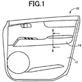
- FIG. 1 is a schematic front view showing the configuration of a vehicle door including a vehicle interior panel 14 (hereinafter simply referred to as the panel 14) according to a preferred embodiment of the present invention, as viewed from the design surface side of the vehicle interior panel 14, namely as viewed from the passenger compartment side (interior side) of a vehicle.
- the panel 14 of the present embodiment is a member that is attached to an inner panel of an automobile door 10, namely to a door inner plate 12, and corresponds to a part of a vehicle door trim that is disposed on the design surface side of the door 10. That is, the present embodiment is described with respect to an example in which the present invention is applied to a vehicle door trim that is attached to a door inner plate.
- the vehicle interior panel of the present invention is also applied in a preferable manner to, e.g., vehicle interior parts such as a luggage side trim, an instrument panel, and an armrest, ornaments that are attached to such interior parts, etc.
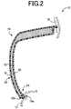
- FIG. 2 is a partial sectional view taken along line II-II and viewed in the direction of arrow II-II in FIG. 1 , showing in detail the configuration around the panel 14.
- the door inner plate 12 (the portion other than the panel 14) is shown by alternate long and short dash lines.
- the panel 14 includes an upholstery material 16, a cushioning material 18, and a base material 22, each being a plate-shaped member curved three-dimensionally into a three-dimensional shape.
- the surface layer member 20 having the upholstery material 16 on the front side and the cushioning material 18 on the back side is bonded to the front surface of the base material 22 such that the upholstery material 16 faces the interior side of the vehicle.
- the surface layer member 20 may be fixed to the base material 22 by fitting a terminal portion of the surface layer member 20 on the base material 22.
- the base material 22 may have a boss etc. on its back surface (on the opposite design surface side), and the surface layer member 20 may be fixed to the base material 22 by engaging the surface layer member 20 with the boss etc.
- the upholstery material 16 corresponds to the upholstery portion and the cushioning material 16 corresponds to the cushioning portion.
- the upholstery material 16 is made of any of various thermoplastic resin materials such as soft polyvinyl chloride, styrene thermoplastic resin materials, olefin thermoplastic resin materials, and polyester thermoplastic resin materials.
- the upholstery material 16 may be made of any of various upholstery materials such as woven or nonwoven fabric, knitted fabric, vinyl chloride, soft films, and natural materials including wool and cowhide.
- the cushioning material 18 is made of a synthetic resin material such as a polypropylene resin or a urethane resin so as to have predetermined elasticity, namely such cushioning properties that the cushioning material 18 is elastically deformed when pressed.
- the synthetic resin material include urethane foam and sponge rubber.
- the base material 22 is made of a relatively hard synthetic resin material such as a polypropylene resin, rigid polyvinyl chloride, an ABS resin, or an AS resin.
- the base material 22 may be made of a wood material, a metal material, etc.
- the panel 14 includes a terminal portion structure 24 in which a fold-back terminal portion 16a of the upholstery material 16 is tucked in around a terminal portion 22a of the base material 22.
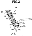
- FIG. 3 is an enlarged partial sectional view of a region around a terminal portion of the panel 14 in FIG. 2 which is located on the lower side of the vehicle, illustrating the terminal portion structure 24.
- the terminal portion of the base material 22 includes an inward flange portion (flange-shaped portion) 26 projecting in the shape of a flange toward the interior side of the vehicle.
- the terminal portion 22a of the base material 22 is bent into the shape of a flange projecting toward the interior side of the vehicle.
- the fold-back terminal portion 16a of the upholstery material 16 is formed by folding back a terminal portion of the upholstery material 16 toward the exterior side of the vehicle (toward the outside of the vehicle, toward the opposite design surface side) so as to tuck in the terminal portion of the upholstery material 16 around the terminal portion 22a of the base material 22 which includes the inward flange portion 26. That is, the terminal portion structure 24 includes the terminal portion 22a of the base material 22 which includes the inward flange portion 26 projecting toward the interior side of the vehicle (the inner side of the vehicle), and the fold-back terminal portion 16a of the upholstery material 16 which is tucked in around the terminal portion 22a.
- the present embodiment is described with respect to an example in which the terminal portion structure 24 is applied to the terminal portion of the panel 14 which is located on the lower side of the vehicle.
- the terminal portion structure 24 of the present embodiment is also applied in a preferable manner to a terminal portion of the panel 14 which is located on the upper side of the vehicle, a terminal portion of the panel 14 which is located on the lateral side (in the lateral direction) of the vehicle, etc.
- the panel 14 has a clearance 28 between a terminal 26a of the inward flange portion 26 and the upholstery material 16. That is, it is ensured that the clearance 28 corresponding to a predetermined interval of, e.g., about 2 mm is present between the terminal (end, edge) 26a of the inward flange portion 26 which is located on the interior side of the vehicle and the inner surface of the upholstery material 16 which is located on the exterior side of the vehicle (the opposite design surface side).
- the inward flange portion 26 projects so that the clearance 28 is present between the inward flange portion 26 and the upholstery material 16.
- the terminal 26a of the inward flange portion 26 is formed by cutting off, e.g., about 2 mm of the tip end of the inward flange portion 26 so as to ensure that the clearance 28 is present between the terminal 26a and the upholstery material 16.
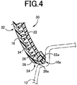
- FIG. 4 is an enlarged sectional view of a region around a terminal portion of a vehicle interior panel 30 (hereinafter simply referred to as the panel 30) which is located on the lower side of a vehicle, illustrating a terminal portion structure 24 of the panel 30 according to another preferred embodiment of the present invention.
- FIG. 4 corresponds to FIG. 3 in the first embodiment.
- an upholstery material 16 that forms a surface layer member 32 is made of, e.g., a synthetic resin material having predetermined elasticity, namely such cushioning properties that the upholstery material 16 is elastically deformed when pressed.
- the upholstery material 16 has multiple elastic projections 34 formed on its surface on the exterior side of the vehicle (the opposite design surface side) so as to project toward a base material 22.
- the multiple elastic projections 34 projecting toward the base material 22 are formed integrally with the upholstery material 16 so that space is created between the upholstery material 16 and the base material 22.
- the upholstery material 16 covers the base material 22 such that at least a part of the elastic projections 34 contacts the surface of the base material 22 which is located on the interior side of the vehicle.
- the tip ends of the elastic projections 34 projecting from the upholstery material 16 are elastically deformed when pressed against the surface of the base material 22, whereby the cushioning properties are provided. That is, in the panel 30 of the present embodiment, the elastic projections 34 formed integrally with the upholstery material 16 correspond to the cushioning portion.
- the multiple elastic projections 34 are preferably formed so as to spread all over the upholstery material 16, and flexural rigidity of each elastic projection 34 against a compressive load is anisotropic about the axis of the elastic projection 34.
- the direction in which each elastic projection 34 projects from the upholstery material 16 is shifted from the direction perpendicular to the upholstery material 16 (e.g., the direction normal to the opposite design surface of the upholstery material 16).
- each elastic projection 34 tends to be flexurally deformed in a specific direction determined by the anisotropy, whereby a soft feel (cushioning properties) is improved.
- each elastic projection 34 is elastically deformed in a stable manner (the direction in which each elastic projection 34 is bent etc.). This restrains variation in tactile feel at the time the upholstery material 16 is pressed with a finger or a hand.
- the panel 30 includes, as the cushioning portion, the elastic projections 34 projecting from the upholstery material 16 toward the base material 22.
- the panel 30 may include multiple elastic projections projecting from the base material 22 toward the upholstery material 16, and these elastic projections may function as the cushioning portion.
- a terminal portion of the base material 22 includes an inward flange portion 26 projecting toward the interior side of the vehicle, and the upholstery material 16 serving as the upholstery portion includes a fold-back terminal portion 16a that is formed by folding back a terminal portion of the upholstery material 16 toward the exterior side of the vehicle so as to tuck in the terminal portion of the upholstery material 16 around a terminal portion 22a of the base material 22 which includes the inward flange portion 26.
- the panel 30 has a clearance 28 between the terminal 26a of the inward flange portion 26 and the upholstery material 16. Accordingly, the cushioning material 18 or the elastic projections 34 which serve as the cushioning portion can be prevented in a preferable manner from being crushed by the fold-back terminal portion 16a of the upholstery material 16.
- the panels 14, 30 can be provided which achieve an improved tactile feel of a terminal portion of a product while ensuring desired design.
- the clearance 28 is present between the inward flange portion 26 and the upholstery material 16. Accordingly, even if the cushioning material 18 is crushed, the inward flange portion 26 is restrained from being pressed against the upholstery material 16. This reduces problems such as the shape of the terminal portion of the inward flange portion 26 showing on the design surface of the upholstery material 16. As a result, desired design of the panels 14, 30 can be ensured.
- the cushioning portion is the elastic projections 34 projecting from the upholstery material 16 toward the base material 22. Accordingly, forming the cushioning portion integrally with the upholstery material 16 can reduce the material cost and can thus achieve cost reduction.
Landscapes
- Engineering & Computer Science (AREA)
- Mechanical Engineering (AREA)
- Vehicle Interior And Exterior Ornaments, Soundproofing, And Insulation (AREA)
Abstract
Description
- The present invention relates to vehicle interior panels, and particularly to an improvement made to improve a tactile feel of a terminal portion of a product while ensuring desired design.
- Vehicle interior panels are known in which a surface layer member including an upholstery portion and a cushioning portion covers the front surface of a base material such that the upholstery portion faces the interior side of a vehicle. A technique of improving a tactile feel of a product is proposed for such vehicle interior panels. One example is a vehicle interior panel described in Patent Document 1. According to this technique, an intermediate member having a cushioning layer is disposed partially between a base material and an upholstery material, and the base material has a recessed portion that accommodates the ends of the intermediate member. This can improve a tactile feel of a part of the interior panel while ensuring desired design.
- Patent Document 1: Japanese Patent Application Publication No.
2014-111347 - In the conventional technique, however, the base material has a smaller thickness in the recessed portion accommodating the intermediate member. This may cause problems such as reduced strength and defective molding due to the difference in thickness. Moreover, the cushioning layer may be crushed by a fold-back terminal portion of the upholstery material, which may degrade design. The inventors discovered these problems while continuing intensive studies with the intention to improve performance of vehicle interior panels.
- The present invention was developed in view of the above circumstances and it is an object of the present invention to provide a vehicle interior panel that improves a tactile feel of a terminal portion of a product while ensuring desired design.
- To achieve the above object, a first aspect of the invention provides a vehicle interior panel in which a surface layer member including an upholstery portion and a cushioning portion covers a front surface of a base material such that the upholstery portion faces an interior side of a vehicle, characterized in that a terminal portion of the base material includes an inward flange portion projecting toward the interior side of the vehicle, the upholstery portion includes a fold-back terminal portion that is formed by folding back a terminal portion of the upholstery portion toward an exterior side of the vehicle so as to tuck in the terminal portion of the upholstery portion around the terminal portion of the base material which includes the inward flange portion, and the vehicle interior panel has a clearance between a terminal of the inward flange portion and the upholstery portion.
- According to the first aspect of the invention, the terminal portion of the base material includes the inward flange portion projecting toward the interior side of the vehicle, and the upholstery portion includes the fold-back terminal portion that is formed by folding back the terminal portion of the upholstery portion toward the exterior side of the vehicle so as to tuck in the terminal portion of the upholstery portion around the terminal portion of the base material which includes the inward flange portion. The vehicle interior panel has the clearance between the terminal of the inward flange portion and the upholstery portion. Accordingly, the cushioning portion can be prevented in a preferable manner from being crushed by the fold-back terminal portion of the upholstery portion. This can ensure a soft tactile feel of a terminal portion of a product and can restrain problems such as reduced strength and defective molding due to the difference in thickness. That is, the vehicle interior panel can be provided which achieve an improved tactile feel of a terminal portion of a product while ensuring desired design.
- A second aspect of the invention provides the vehicle interior panel recited in the first aspect of the invention, wherein the cushioning portion is an elastic projection projecting from the upholstery portion toward the base material. Accordingly, forming the cushioning portion integrally with the upholstery portion can reduce the material cost and can thus achieve cost reduction.
-
-
FIG. 1 is a schematic front view showing the configuration of a vehicle door including a vehicle interior panel according to a preferred embodiment of the present invention. -
FIG. 2 is a sectional view taken along line II-II and viewed in the direction of arrow II-II inFIG. 1 . -
FIG. 3 is an enlarged partial sectional view of a region around a terminal portion of the vehicle interior panel inFIG. 2 which is located on the lower side of the vehicle. -
FIG. 4 is an enlarged sectional view of a region around a terminal portion of a vehicle interior panel according to another preferred embodiment of the present invention which is located on the lower side of a vehicle. - Preferred embodiments of the present invention will be described in detail below with reference to the accompanying drawings. In the figures used in the following description, each part is not necessarily drawn at an accurate dimensional ratio etc.
-
FIG. 1 is a schematic front view showing the configuration of a vehicle door including a vehicle interior panel 14 (hereinafter simply referred to as the panel 14) according to a preferred embodiment of the present invention, as viewed from the design surface side of thevehicle interior panel 14, namely as viewed from the passenger compartment side (interior side) of a vehicle. As shown inFIG. 1 , thepanel 14 of the present embodiment is a member that is attached to an inner panel of anautomobile door 10, namely to a doorinner plate 12, and corresponds to a part of a vehicle door trim that is disposed on the design surface side of thedoor 10. That is, the present embodiment is described with respect to an example in which the present invention is applied to a vehicle door trim that is attached to a door inner plate. However, the vehicle interior panel of the present invention is also applied in a preferable manner to, e.g., vehicle interior parts such as a luggage side trim, an instrument panel, and an armrest, ornaments that are attached to such interior parts, etc. -
FIG. 2 is a partial sectional view taken along line II-II and viewed in the direction of arrow II-II inFIG. 1 , showing in detail the configuration around thepanel 14. InFIGS. 2 to 4 , the door inner plate 12 (the portion other than the panel 14) is shown by alternate long and short dash lines. As shown inFIG. 2 , thepanel 14 includes anupholstery material 16, acushioning material 18, and abase material 22, each being a plate-shaped member curved three-dimensionally into a three-dimensional shape. Asurface layer member 20, which is a laminate of theupholstery material 16 and thecushioning material 18, covers the front surface (surface on the interior side of the vehicle) of thebase material 22 such that theupholstery material 16 faces the interior side (passenger compartment side) of the vehicle. In other words, thesurface layer member 20 having theupholstery material 16 on the front side and thecushioning material 18 on the back side is bonded to the front surface of thebase material 22 such that theupholstery material 16 faces the interior side of the vehicle. Alternatively, thesurface layer member 20 may be fixed to thebase material 22 by fitting a terminal portion of thesurface layer member 20 on thebase material 22. Thebase material 22 may have a boss etc. on its back surface (on the opposite design surface side), and thesurface layer member 20 may be fixed to thebase material 22 by engaging thesurface layer member 20 with the boss etc. In thepanel 14, theupholstery material 16 corresponds to the upholstery portion and thecushioning material 16 corresponds to the cushioning portion. - For example, the
upholstery material 16 is made of any of various thermoplastic resin materials such as soft polyvinyl chloride, styrene thermoplastic resin materials, olefin thermoplastic resin materials, and polyester thermoplastic resin materials. Alternatively, theupholstery material 16 may be made of any of various upholstery materials such as woven or nonwoven fabric, knitted fabric, vinyl chloride, soft films, and natural materials including wool and cowhide. For example, thecushioning material 18 is made of a synthetic resin material such as a polypropylene resin or a urethane resin so as to have predetermined elasticity, namely such cushioning properties that thecushioning material 18 is elastically deformed when pressed. Preferred examples of the synthetic resin material include urethane foam and sponge rubber. For example, thebase material 22 is made of a relatively hard synthetic resin material such as a polypropylene resin, rigid polyvinyl chloride, an ABS resin, or an AS resin. Thebase material 22 may be made of a wood material, a metal material, etc. - The
panel 14 includes aterminal portion structure 24 in which a fold-back terminal portion 16a of theupholstery material 16 is tucked in around aterminal portion 22a of thebase material 22.FIG. 3 is an enlarged partial sectional view of a region around a terminal portion of thepanel 14 inFIG. 2 which is located on the lower side of the vehicle, illustrating theterminal portion structure 24. As shown inFIG. 3 , the terminal portion of thebase material 22 includes an inward flange portion (flange-shaped portion) 26 projecting in the shape of a flange toward the interior side of the vehicle. In other words, theterminal portion 22a of thebase material 22 is bent into the shape of a flange projecting toward the interior side of the vehicle. The fold-back terminal portion 16a of theupholstery material 16 is formed by folding back a terminal portion of theupholstery material 16 toward the exterior side of the vehicle (toward the outside of the vehicle, toward the opposite design surface side) so as to tuck in the terminal portion of theupholstery material 16 around theterminal portion 22a of thebase material 22 which includes theinward flange portion 26. That is, theterminal portion structure 24 includes theterminal portion 22a of thebase material 22 which includes theinward flange portion 26 projecting toward the interior side of the vehicle (the inner side of the vehicle), and the fold-back terminal portion 16a of theupholstery material 16 which is tucked in around theterminal portion 22a. The present embodiment is described with respect to an example in which theterminal portion structure 24 is applied to the terminal portion of thepanel 14 which is located on the lower side of the vehicle. However, theterminal portion structure 24 of the present embodiment is also applied in a preferable manner to a terminal portion of thepanel 14 which is located on the upper side of the vehicle, a terminal portion of thepanel 14 which is located on the lateral side (in the lateral direction) of the vehicle, etc. - In the
terminal portion structure 24, thepanel 14 has aclearance 28 between aterminal 26a of theinward flange portion 26 and theupholstery material 16. That is, it is ensured that theclearance 28 corresponding to a predetermined interval of, e.g., about 2 mm is present between the terminal (end, edge) 26a of theinward flange portion 26 which is located on the interior side of the vehicle and the inner surface of theupholstery material 16 which is located on the exterior side of the vehicle (the opposite design surface side). In other words, theinward flange portion 26 projects so that theclearance 28 is present between theinward flange portion 26 and theupholstery material 16. Theterminal 26a of theinward flange portion 26 is formed by cutting off, e.g., about 2 mm of the tip end of theinward flange portion 26 so as to ensure that theclearance 28 is present between theterminal 26a and theupholstery material 16. - Still another preferred embodiment of the present invention will be described in detail below with reference to the drawings. In the figure used in the following description, those portions common to the embodiments are denoted with the same reference characters and description thereof will be omitted.
-
FIG. 4 is an enlarged sectional view of a region around a terminal portion of a vehicle interior panel 30 (hereinafter simply referred to as the panel 30) which is located on the lower side of a vehicle, illustrating aterminal portion structure 24 of thepanel 30 according to another preferred embodiment of the present invention.FIG. 4 corresponds toFIG. 3 in the first embodiment. In thepanel 30 of the present embodiment, anupholstery material 16 that forms asurface layer member 32 is made of, e.g., a synthetic resin material having predetermined elasticity, namely such cushioning properties that theupholstery material 16 is elastically deformed when pressed. Theupholstery material 16 has multipleelastic projections 34 formed on its surface on the exterior side of the vehicle (the opposite design surface side) so as to project toward abase material 22. That is, the multipleelastic projections 34 projecting toward thebase material 22 are formed integrally with theupholstery material 16 so that space is created between theupholstery material 16 and thebase material 22. Theupholstery material 16 covers thebase material 22 such that at least a part of theelastic projections 34 contacts the surface of thebase material 22 which is located on the interior side of the vehicle. In thepanel 30, the tip ends of theelastic projections 34 projecting from theupholstery material 16 are elastically deformed when pressed against the surface of thebase material 22, whereby the cushioning properties are provided. That is, in thepanel 30 of the present embodiment, theelastic projections 34 formed integrally with theupholstery material 16 correspond to the cushioning portion. - The multiple
elastic projections 34 are preferably formed so as to spread all over theupholstery material 16, and flexural rigidity of eachelastic projection 34 against a compressive load is anisotropic about the axis of theelastic projection 34. For example, the direction in which eachelastic projection 34 projects from theupholstery material 16 is shifted from the direction perpendicular to the upholstery material 16 (e.g., the direction normal to the opposite design surface of the upholstery material 16). There may be an elastic projection(s) 34 that projects in the direction perpendicular to theupholstery material 16. With this configuration, flexural rigidity of eachelastic projection 34 against a compressive load is anisotropic about the axis of theelastic projection 34. Accordingly, for example, when theupholstery material 16 is pressed in a substantially perpendicular direction from the interior side of the vehicle (the design surface side), eachelastic projection 34 tends to be flexurally deformed in a specific direction determined by the anisotropy, whereby a soft feel (cushioning properties) is improved. Moreover, since the direction in which eachelastic projection 34 is bent (buckled) can be controlled, eachelastic projection 34 is elastically deformed in a stable manner (the direction in which eachelastic projection 34 is bent etc.). This restrains variation in tactile feel at the time theupholstery material 16 is pressed with a finger or a hand. - The
panel 30 includes, as the cushioning portion, theelastic projections 34 projecting from theupholstery material 16 toward thebase material 22. However, thepanel 30 may include multiple elastic projections projecting from thebase material 22 toward theupholstery material 16, and these elastic projections may function as the cushioning portion. - According to the embodiment described above, a terminal portion of the
base material 22 includes aninward flange portion 26 projecting toward the interior side of the vehicle, and theupholstery material 16 serving as the upholstery portion includes a fold-back terminal portion 16a that is formed by folding back a terminal portion of theupholstery material 16 toward the exterior side of the vehicle so as to tuck in the terminal portion of theupholstery material 16 around aterminal portion 22a of thebase material 22 which includes theinward flange portion 26. Thepanel 30 has aclearance 28 between the terminal 26a of theinward flange portion 26 and theupholstery material 16. Accordingly, the cushioningmaterial 18 or theelastic projections 34 which serve as the cushioning portion can be prevented in a preferable manner from being crushed by the fold-back terminal portion 16a of theupholstery material 16. This can ensure a soft tactile feel of a terminal portion of a product and can restrain problems such as reduced strength and defective molding due to the difference in thickness. That is, thepanels - According to the present embodiment, the
clearance 28 is present between theinward flange portion 26 and theupholstery material 16. Accordingly, even if thecushioning material 18 is crushed, theinward flange portion 26 is restrained from being pressed against theupholstery material 16. This reduces problems such as the shape of the terminal portion of theinward flange portion 26 showing on the design surface of theupholstery material 16. As a result, desired design of thepanels - In the
panel 30, the cushioning portion is theelastic projections 34 projecting from theupholstery material 16 toward thebase material 22. Accordingly, forming the cushioning portion integrally with theupholstery material 16 can reduce the material cost and can thus achieve cost reduction. - Although the preferred embodiments of the present invention are described in detail above based on the drawings, the present invention is not limited to these embodiments and can be carried out in various modified forms without departing from the spirit and scope of the invention.
-
- 14, 30: Vehicle interior panel 16: Upholstery material (Upholstery portion) 16a: Fold-back terminal portion 18: Cushioning material (Cushioning portion) 20, 32: Surface layer member 22:
Base material 22a: Terminal portion 26:Inward flange portion 26a: Terminal 28: Clearance 34: Elastic projection (Cushioning portion)
Claims (2)
- A vehicle interior panel in which a surface layer member including an upholstery portion and a cushioning portion covers a front surface of a base material such that the upholstery portion faces an interior side of a vehicle, characterized in that
a terminal portion of the base material includes an inward flange portion projecting toward the interior side of the vehicle,
the upholstery portion includes a fold-back terminal portion that is formed by folding back a terminal portion of the upholstery portion toward an exterior side of the vehicle so as to tuck in the terminal portion of the upholstery portion around the terminal portion of the base material which includes the inward flange portion, and
the vehicle interior panel has a clearance between a terminal of the inward flange portion and the upholstery portion. - The vehicle interior panel according to claim 1, wherein
the cushioning portion is an elastic projection projecting from the upholstery portion toward the base material.
Applications Claiming Priority (2)
| Application Number | Priority Date | Filing Date | Title |
|---|---|---|---|
| JP2014247472A JP2016107840A (en) | 2014-12-05 | 2014-12-05 | Vehicle interior panel |
| PCT/JP2015/082962 WO2016088606A1 (en) | 2014-12-05 | 2015-11-24 | Vehicular interior panel |
Publications (3)
| Publication Number | Publication Date |
|---|---|
| EP3228503A1 true EP3228503A1 (en) | 2017-10-11 |
| EP3228503A4 EP3228503A4 (en) | 2018-05-30 |
| EP3228503B1 EP3228503B1 (en) | 2020-05-06 |
Family
ID=56091555
Family Applications (1)
| Application Number | Title | Priority Date | Filing Date |
|---|---|---|---|
| EP15864750.3A Active EP3228503B1 (en) | 2014-12-05 | 2015-11-24 | Vehicular interior panel |
Country Status (4)
| Country | Link |
|---|---|
| US (1) | US10059282B2 (en) |
| EP (1) | EP3228503B1 (en) |
| JP (1) | JP2016107840A (en) |
| WO (1) | WO2016088606A1 (en) |
Families Citing this family (6)
| Publication number | Priority date | Publication date | Assignee | Title |
|---|---|---|---|---|
| US10293762B2 (en) | 2014-11-26 | 2019-05-21 | Toyota Iron Works Co., Ltd. | Vehicular interior component, vehicular interior panel, and vehicular composite interior component |
| US11046258B2 (en) * | 2019-08-20 | 2021-06-29 | Toyota Motor Engineering & Manufacturing North America, Inc. | Methods of visually checking for alignment between instrument panel ornaments and door ornaments using alignment tools |
| JP7800267B2 (en) * | 2022-04-01 | 2026-01-16 | トヨタ紡織株式会社 | Interior parts |
| JP2024016961A (en) * | 2022-07-27 | 2024-02-08 | 株式会社イノアックコーポレーション | Interior member |
| USD1026766S1 (en) * | 2022-11-13 | 2024-05-14 | Atieva, Inc. | Automotive vehicle front door |
| KR20240120913A (en) * | 2023-02-01 | 2024-08-08 | 현대자동차주식회사 | Door armrest of vehicle |
Family Cites Families (28)
| Publication number | Priority date | Publication date | Assignee | Title |
|---|---|---|---|---|
| JPH0524813Y2 (en) | 1988-07-06 | 1993-06-23 | ||
| JPH03200448A (en) * | 1989-12-28 | 1991-09-02 | Hayashi Terenpu Kk | Breaking away method for resin layer leaving skin layer |
| US5181759A (en) * | 1992-02-21 | 1993-01-26 | General Motors Corporation | Collapsible arm rest |
| JP3158910B2 (en) | 1994-12-09 | 2001-04-23 | 三菱自動車工業株式会社 | Pull handle combined with door grip for vehicle |
| JP3957634B2 (en) * | 2000-12-06 | 2007-08-15 | ブローゼ・ファールツォイクタイレ・ゲーエムベーハー・ウント・コンパニ・コマンディットゲゼルシャフト・コーブルク | Armrest assembly for automobile doors |
| JP2003103676A (en) * | 2001-09-28 | 2003-04-09 | Inoac Corp | Resin molded member |
| JP4063643B2 (en) * | 2002-11-18 | 2008-03-19 | テイ・エス テック株式会社 | Vehicle seat terminal processing apparatus and vehicle seat terminal processing method |
| US20060220414A1 (en) * | 2003-01-07 | 2006-10-05 | Johnson Controls Technology Company | Vehicle door panel and component assembly mounted through the panel |
| JP4247893B2 (en) * | 2003-10-15 | 2009-04-02 | 河西工業株式会社 | Interior parts for automobiles and manufacturing method thereof |
| JP2006213134A (en) | 2005-02-02 | 2006-08-17 | Kasai Kogyo Co Ltd | Arm rest for vehicle |
| FR2884202B1 (en) * | 2005-04-12 | 2007-06-29 | Faurecia Interieur Ind Snc | EQUIPMENT PIECE FOR MOTOR VEHICLE AND ASSOCIATED MOUNTING METHOD |
| US20070108830A1 (en) * | 2005-11-14 | 2007-05-17 | Lear Corporation | Door armrest system with pull cup |
| US20070278809A1 (en) * | 2006-06-04 | 2007-12-06 | Lear Corporation | Living Hinge Belt Line Vacuum Form Edge Wrap |
| JP2009298383A (en) | 2008-06-17 | 2009-12-24 | Kasai Kogyo Co Ltd | Automobile interior component |
| JP5299055B2 (en) * | 2009-04-21 | 2013-09-25 | 日産自動車株式会社 | Interior parts for vehicles |
| JP5406816B2 (en) * | 2010-11-02 | 2014-02-05 | 豊田鉄工株式会社 | Vehicle door trim |
| RU2578300C1 (en) * | 2012-03-07 | 2016-03-27 | Тоеда Айрон Уоркс Ко., Лтд | Covering composite component |
| JP2013184603A (en) * | 2012-03-08 | 2013-09-19 | Ts Tech Co Ltd | Interior material |
| JP2014111347A (en) | 2012-08-13 | 2014-06-19 | Toyota Auto Body Co Ltd | Interior panel for vehicle and method for manufacturing interior panel for vehicle |
| JP5974398B2 (en) | 2012-11-14 | 2016-08-23 | トヨタ紡織株式会社 | Vehicle door trim |
| JP5767200B2 (en) | 2012-11-27 | 2015-08-19 | 豊田鉄工株式会社 | Overlapped composite parts |
| JP5950814B2 (en) * | 2012-12-26 | 2016-07-13 | 豊田鉄工株式会社 | Overlapped composite parts |
| EP3045305B1 (en) * | 2013-09-13 | 2020-08-19 | Toyoda Iron Works Co., Ltd. | Multilayer composite interior component |
| JP6207074B2 (en) * | 2013-12-19 | 2017-10-04 | ダイキョーニシカワ株式会社 | Vehicle door trim |
| JP6111217B2 (en) | 2014-04-02 | 2017-04-05 | 豊田鉄工株式会社 | Overlapped composite parts |
| JP6161648B2 (en) | 2014-05-26 | 2017-07-12 | 豊田鉄工株式会社 | Stacked composite interior parts |
| JP6363512B2 (en) | 2015-01-09 | 2018-07-25 | 豊田鉄工株式会社 | Composite interior parts for vehicles |
| US10293762B2 (en) | 2014-11-26 | 2019-05-21 | Toyota Iron Works Co., Ltd. | Vehicular interior component, vehicular interior panel, and vehicular composite interior component |
-
2014
- 2014-12-05 JP JP2014247472A patent/JP2016107840A/en active Pending
-
2015
- 2015-11-24 US US15/532,217 patent/US10059282B2/en not_active Expired - Fee Related
- 2015-11-24 EP EP15864750.3A patent/EP3228503B1/en active Active
- 2015-11-24 WO PCT/JP2015/082962 patent/WO2016088606A1/en not_active Ceased
Also Published As
| Publication number | Publication date |
|---|---|
| WO2016088606A1 (en) | 2016-06-09 |
| JP2016107840A (en) | 2016-06-20 |
| EP3228503A4 (en) | 2018-05-30 |
| US10059282B2 (en) | 2018-08-28 |
| EP3228503B1 (en) | 2020-05-06 |
| US20170267189A1 (en) | 2017-09-21 |
Similar Documents
| Publication | Publication Date | Title |
|---|---|---|
| US10059282B2 (en) | Vehicular interior panel | |
| US9505356B2 (en) | Vehicular interior part | |
| US8764891B1 (en) | Headliner edge treatment | |
| JP7054930B2 (en) | Vehicle interior materials | |
| JP5607375B2 (en) | Interior parts and console box | |
| CN105793106B (en) | The epidermis method of sewing of the epigenetic structure of seat with choke material and seat with choke material | |
| US20150015053A1 (en) | Seat for vehicle | |
| US10293762B2 (en) | Vehicular interior component, vehicular interior panel, and vehicular composite interior component | |
| JP2013220761A (en) | Interior part and working tool for manufacturing interior part | |
| US20140312641A1 (en) | Vehicle interior component with stitching | |
| JP4837478B2 (en) | Molded product with cover, foamed product with integrated cover and headrest | |
| JP3620697B2 (en) | Vehicle armrest | |
| JP2016128300A (en) | Vehicular composite interior component | |
| CN104626938B (en) | Vehicle door | |
| JP2012228910A (en) | Door trim | |
| JP4197138B2 (en) | Vehicle armrest | |
| JP2007038845A (en) | Armrest for vehicle | |
| JP2014051180A (en) | Vehicle floor carpet | |
| JP4563139B2 (en) | Structure to prevent peeling of car interior parts | |
| JP6966094B2 (en) | Interior materials for vehicles | |
| JP2021084471A (en) | Storage device | |
| JP2016107839A (en) | Interior part for vehicle | |
| JP2015000287A (en) | Vehicular interior member | |
| JP2015217695A (en) | Vehicular interior material | |
| JP2019151267A (en) | Vehicle interior member |
Legal Events
| Date | Code | Title | Description |
|---|---|---|---|
| STAA | Information on the status of an ep patent application or granted ep patent |
Free format text: STATUS: THE INTERNATIONAL PUBLICATION HAS BEEN MADE |
|
| PUAI | Public reference made under article 153(3) epc to a published international application that has entered the european phase |
Free format text: ORIGINAL CODE: 0009012 |
|
| STAA | Information on the status of an ep patent application or granted ep patent |
Free format text: STATUS: REQUEST FOR EXAMINATION WAS MADE |
|
| 17P | Request for examination filed |
Effective date: 20170616 |
|
| AK | Designated contracting states |
Kind code of ref document: A1 Designated state(s): AL AT BE BG CH CY CZ DE DK EE ES FI FR GB GR HR HU IE IS IT LI LT LU LV MC MK MT NL NO PL PT RO RS SE SI SK SM TR |
|
| AX | Request for extension of the european patent |
Extension state: BA ME |
|
| DAV | Request for validation of the european patent (deleted) | ||
| DAX | Request for extension of the european patent (deleted) | ||
| A4 | Supplementary search report drawn up and despatched |
Effective date: 20180503 |
|
| RIC1 | Information provided on ipc code assigned before grant |
Ipc: B60R 13/02 20060101AFI20180425BHEP |
|
| STAA | Information on the status of an ep patent application or granted ep patent |
Free format text: STATUS: EXAMINATION IS IN PROGRESS |
|
| 17Q | First examination report despatched |
Effective date: 20190320 |
|
| GRAP | Despatch of communication of intention to grant a patent |
Free format text: ORIGINAL CODE: EPIDOSNIGR1 |
|
| STAA | Information on the status of an ep patent application or granted ep patent |
Free format text: STATUS: GRANT OF PATENT IS INTENDED |
|
| INTG | Intention to grant announced |
Effective date: 20200203 |
|
| GRAS | Grant fee paid |
Free format text: ORIGINAL CODE: EPIDOSNIGR3 |
|
| GRAA | (expected) grant |
Free format text: ORIGINAL CODE: 0009210 |
|
| STAA | Information on the status of an ep patent application or granted ep patent |
Free format text: STATUS: THE PATENT HAS BEEN GRANTED |
|
| AK | Designated contracting states |
Kind code of ref document: B1 Designated state(s): AL AT BE BG CH CY CZ DE DK EE ES FI FR GB GR HR HU IE IS IT LI LT LU LV MC MK MT NL NO PL PT RO RS SE SI SK SM TR |
|
| REG | Reference to a national code |
Ref country code: GB Ref legal event code: FG4D |
|
| REG | Reference to a national code |
Ref country code: CH Ref legal event code: EP Ref country code: AT Ref legal event code: REF Ref document number: 1266244 Country of ref document: AT Kind code of ref document: T Effective date: 20200515 |
|
| REG | Reference to a national code |
Ref country code: IE Ref legal event code: FG4D |
|
| REG | Reference to a national code |
Ref country code: DE Ref legal event code: R096 Ref document number: 602015052529 Country of ref document: DE |
|
| REG | Reference to a national code |
Ref country code: LT Ref legal event code: MG4D |
|
| REG | Reference to a national code |
Ref country code: NL Ref legal event code: MP Effective date: 20200506 |
|
| PG25 | Lapsed in a contracting state [announced via postgrant information from national office to epo] |
Ref country code: LT Free format text: LAPSE BECAUSE OF FAILURE TO SUBMIT A TRANSLATION OF THE DESCRIPTION OR TO PAY THE FEE WITHIN THE PRESCRIBED TIME-LIMIT Effective date: 20200506 Ref country code: FI Free format text: LAPSE BECAUSE OF FAILURE TO SUBMIT A TRANSLATION OF THE DESCRIPTION OR TO PAY THE FEE WITHIN THE PRESCRIBED TIME-LIMIT Effective date: 20200506 Ref country code: SE Free format text: LAPSE BECAUSE OF FAILURE TO SUBMIT A TRANSLATION OF THE DESCRIPTION OR TO PAY THE FEE WITHIN THE PRESCRIBED TIME-LIMIT Effective date: 20200506 Ref country code: IS Free format text: LAPSE BECAUSE OF FAILURE TO SUBMIT A TRANSLATION OF THE DESCRIPTION OR TO PAY THE FEE WITHIN THE PRESCRIBED TIME-LIMIT Effective date: 20200906 Ref country code: NO Free format text: LAPSE BECAUSE OF FAILURE TO SUBMIT A TRANSLATION OF THE DESCRIPTION OR TO PAY THE FEE WITHIN THE PRESCRIBED TIME-LIMIT Effective date: 20200806 Ref country code: GR Free format text: LAPSE BECAUSE OF FAILURE TO SUBMIT A TRANSLATION OF THE DESCRIPTION OR TO PAY THE FEE WITHIN THE PRESCRIBED TIME-LIMIT Effective date: 20200807 Ref country code: PT Free format text: LAPSE BECAUSE OF FAILURE TO SUBMIT A TRANSLATION OF THE DESCRIPTION OR TO PAY THE FEE WITHIN THE PRESCRIBED TIME-LIMIT Effective date: 20200907 |
|
| PG25 | Lapsed in a contracting state [announced via postgrant information from national office to epo] |
Ref country code: HR Free format text: LAPSE BECAUSE OF FAILURE TO SUBMIT A TRANSLATION OF THE DESCRIPTION OR TO PAY THE FEE WITHIN THE PRESCRIBED TIME-LIMIT Effective date: 20200506 Ref country code: RS Free format text: LAPSE BECAUSE OF FAILURE TO SUBMIT A TRANSLATION OF THE DESCRIPTION OR TO PAY THE FEE WITHIN THE PRESCRIBED TIME-LIMIT Effective date: 20200506 Ref country code: LV Free format text: LAPSE BECAUSE OF FAILURE TO SUBMIT A TRANSLATION OF THE DESCRIPTION OR TO PAY THE FEE WITHIN THE PRESCRIBED TIME-LIMIT Effective date: 20200506 Ref country code: BG Free format text: LAPSE BECAUSE OF FAILURE TO SUBMIT A TRANSLATION OF THE DESCRIPTION OR TO PAY THE FEE WITHIN THE PRESCRIBED TIME-LIMIT Effective date: 20200806 |
|
| REG | Reference to a national code |
Ref country code: AT Ref legal event code: MK05 Ref document number: 1266244 Country of ref document: AT Kind code of ref document: T Effective date: 20200506 |
|
| PG25 | Lapsed in a contracting state [announced via postgrant information from national office to epo] |
Ref country code: AL Free format text: LAPSE BECAUSE OF FAILURE TO SUBMIT A TRANSLATION OF THE DESCRIPTION OR TO PAY THE FEE WITHIN THE PRESCRIBED TIME-LIMIT Effective date: 20200506 Ref country code: NL Free format text: LAPSE BECAUSE OF FAILURE TO SUBMIT A TRANSLATION OF THE DESCRIPTION OR TO PAY THE FEE WITHIN THE PRESCRIBED TIME-LIMIT Effective date: 20200506 |
|
| PG25 | Lapsed in a contracting state [announced via postgrant information from national office to epo] |
Ref country code: ES Free format text: LAPSE BECAUSE OF FAILURE TO SUBMIT A TRANSLATION OF THE DESCRIPTION OR TO PAY THE FEE WITHIN THE PRESCRIBED TIME-LIMIT Effective date: 20200506 Ref country code: EE Free format text: LAPSE BECAUSE OF FAILURE TO SUBMIT A TRANSLATION OF THE DESCRIPTION OR TO PAY THE FEE WITHIN THE PRESCRIBED TIME-LIMIT Effective date: 20200506 Ref country code: SM Free format text: LAPSE BECAUSE OF FAILURE TO SUBMIT A TRANSLATION OF THE DESCRIPTION OR TO PAY THE FEE WITHIN THE PRESCRIBED TIME-LIMIT Effective date: 20200506 Ref country code: DK Free format text: LAPSE BECAUSE OF FAILURE TO SUBMIT A TRANSLATION OF THE DESCRIPTION OR TO PAY THE FEE WITHIN THE PRESCRIBED TIME-LIMIT Effective date: 20200506 Ref country code: RO Free format text: LAPSE BECAUSE OF FAILURE TO SUBMIT A TRANSLATION OF THE DESCRIPTION OR TO PAY THE FEE WITHIN THE PRESCRIBED TIME-LIMIT Effective date: 20200506 Ref country code: IT Free format text: LAPSE BECAUSE OF FAILURE TO SUBMIT A TRANSLATION OF THE DESCRIPTION OR TO PAY THE FEE WITHIN THE PRESCRIBED TIME-LIMIT Effective date: 20200506 Ref country code: AT Free format text: LAPSE BECAUSE OF FAILURE TO SUBMIT A TRANSLATION OF THE DESCRIPTION OR TO PAY THE FEE WITHIN THE PRESCRIBED TIME-LIMIT Effective date: 20200506 Ref country code: CZ Free format text: LAPSE BECAUSE OF FAILURE TO SUBMIT A TRANSLATION OF THE DESCRIPTION OR TO PAY THE FEE WITHIN THE PRESCRIBED TIME-LIMIT Effective date: 20200506 |
|
| REG | Reference to a national code |
Ref country code: DE Ref legal event code: R097 Ref document number: 602015052529 Country of ref document: DE |
|
| PG25 | Lapsed in a contracting state [announced via postgrant information from national office to epo] |
Ref country code: PL Free format text: LAPSE BECAUSE OF FAILURE TO SUBMIT A TRANSLATION OF THE DESCRIPTION OR TO PAY THE FEE WITHIN THE PRESCRIBED TIME-LIMIT Effective date: 20200506 Ref country code: SK Free format text: LAPSE BECAUSE OF FAILURE TO SUBMIT A TRANSLATION OF THE DESCRIPTION OR TO PAY THE FEE WITHIN THE PRESCRIBED TIME-LIMIT Effective date: 20200506 |
|
| PLBE | No opposition filed within time limit |
Free format text: ORIGINAL CODE: 0009261 |
|
| STAA | Information on the status of an ep patent application or granted ep patent |
Free format text: STATUS: NO OPPOSITION FILED WITHIN TIME LIMIT |
|
| 26N | No opposition filed |
Effective date: 20210209 |
|
| PG25 | Lapsed in a contracting state [announced via postgrant information from national office to epo] |
Ref country code: SI Free format text: LAPSE BECAUSE OF FAILURE TO SUBMIT A TRANSLATION OF THE DESCRIPTION OR TO PAY THE FEE WITHIN THE PRESCRIBED TIME-LIMIT Effective date: 20200506 |
|
| PG25 | Lapsed in a contracting state [announced via postgrant information from national office to epo] |
Ref country code: MC Free format text: LAPSE BECAUSE OF FAILURE TO SUBMIT A TRANSLATION OF THE DESCRIPTION OR TO PAY THE FEE WITHIN THE PRESCRIBED TIME-LIMIT Effective date: 20200506 |
|
| REG | Reference to a national code |
Ref country code: CH Ref legal event code: PL |
|
| PG25 | Lapsed in a contracting state [announced via postgrant information from national office to epo] |
Ref country code: LU Free format text: LAPSE BECAUSE OF NON-PAYMENT OF DUE FEES Effective date: 20201124 |
|
| REG | Reference to a national code |
Ref country code: BE Ref legal event code: MM Effective date: 20201130 |
|
| PG25 | Lapsed in a contracting state [announced via postgrant information from national office to epo] |
Ref country code: LI Free format text: LAPSE BECAUSE OF NON-PAYMENT OF DUE FEES Effective date: 20201130 Ref country code: CH Free format text: LAPSE BECAUSE OF NON-PAYMENT OF DUE FEES Effective date: 20201130 |
|
| PG25 | Lapsed in a contracting state [announced via postgrant information from national office to epo] |
Ref country code: IE Free format text: LAPSE BECAUSE OF NON-PAYMENT OF DUE FEES Effective date: 20201124 |
|
| PGFP | Annual fee paid to national office [announced via postgrant information from national office to epo] |
Ref country code: GB Payment date: 20210930 Year of fee payment: 7 |
|
| PGFP | Annual fee paid to national office [announced via postgrant information from national office to epo] |
Ref country code: DE Payment date: 20210929 Year of fee payment: 7 Ref country code: FR Payment date: 20211109 Year of fee payment: 7 |
|
| PG25 | Lapsed in a contracting state [announced via postgrant information from national office to epo] |
Ref country code: TR Free format text: LAPSE BECAUSE OF FAILURE TO SUBMIT A TRANSLATION OF THE DESCRIPTION OR TO PAY THE FEE WITHIN THE PRESCRIBED TIME-LIMIT Effective date: 20200506 Ref country code: MT Free format text: LAPSE BECAUSE OF FAILURE TO SUBMIT A TRANSLATION OF THE DESCRIPTION OR TO PAY THE FEE WITHIN THE PRESCRIBED TIME-LIMIT Effective date: 20200506 Ref country code: CY Free format text: LAPSE BECAUSE OF FAILURE TO SUBMIT A TRANSLATION OF THE DESCRIPTION OR TO PAY THE FEE WITHIN THE PRESCRIBED TIME-LIMIT Effective date: 20200506 |
|
| PG25 | Lapsed in a contracting state [announced via postgrant information from national office to epo] |
Ref country code: MK Free format text: LAPSE BECAUSE OF FAILURE TO SUBMIT A TRANSLATION OF THE DESCRIPTION OR TO PAY THE FEE WITHIN THE PRESCRIBED TIME-LIMIT Effective date: 20200506 |
|
| PG25 | Lapsed in a contracting state [announced via postgrant information from national office to epo] |
Ref country code: BE Free format text: LAPSE BECAUSE OF NON-PAYMENT OF DUE FEES Effective date: 20201130 |
|
| REG | Reference to a national code |
Ref country code: DE Ref legal event code: R119 Ref document number: 602015052529 Country of ref document: DE |
|
| GBPC | Gb: european patent ceased through non-payment of renewal fee |
Effective date: 20221124 |
|
| PG25 | Lapsed in a contracting state [announced via postgrant information from national office to epo] |
Ref country code: GB Free format text: LAPSE BECAUSE OF NON-PAYMENT OF DUE FEES Effective date: 20221124 Ref country code: DE Free format text: LAPSE BECAUSE OF NON-PAYMENT OF DUE FEES Effective date: 20230601 |
|
| PG25 | Lapsed in a contracting state [announced via postgrant information from national office to epo] |
Ref country code: FR Free format text: LAPSE BECAUSE OF NON-PAYMENT OF DUE FEES Effective date: 20221130 |