EP3228444A1 - Pressing unit for removing liquids - Google Patents
Pressing unit for removing liquids Download PDFInfo
- Publication number
- EP3228444A1 EP3228444A1 EP16425028.4A EP16425028A EP3228444A1 EP 3228444 A1 EP3228444 A1 EP 3228444A1 EP 16425028 A EP16425028 A EP 16425028A EP 3228444 A1 EP3228444 A1 EP 3228444A1
- Authority
- EP
- European Patent Office
- Prior art keywords
- roller
- path
- pressing unit
- chamber
- unit according
- Prior art date
- Legal status (The legal status is an assumption and is not a legal conclusion. Google has not performed a legal analysis and makes no representation as to the accuracy of the status listed.)
- Granted
Links
- 238000003825 pressing Methods 0.000 title claims abstract description 35
- 239000007788 liquid Substances 0.000 title claims abstract description 27
- 239000000463 material Substances 0.000 claims abstract description 51
- 230000000295 complement effect Effects 0.000 claims abstract description 8
- 230000000750 progressive effect Effects 0.000 claims description 4
- 230000009467 reduction Effects 0.000 claims description 4
- 230000007423 decrease Effects 0.000 claims description 3
- XLYOFNOQVPJJNP-UHFFFAOYSA-N water Substances O XLYOFNOQVPJJNP-UHFFFAOYSA-N 0.000 description 25
- 239000002184 metal Substances 0.000 description 10
- 238000000034 method Methods 0.000 description 8
- 230000008569 process Effects 0.000 description 6
- 239000000047 product Substances 0.000 description 6
- 238000003466 welding Methods 0.000 description 5
- 238000001035 drying Methods 0.000 description 4
- 230000001681 protective effect Effects 0.000 description 4
- 235000016068 Berberis vulgaris Nutrition 0.000 description 3
- 241000335053 Beta vulgaris Species 0.000 description 3
- 230000002159 abnormal effect Effects 0.000 description 3
- 230000003247 decreasing effect Effects 0.000 description 3
- 239000000126 substance Substances 0.000 description 3
- 230000018044 dehydration Effects 0.000 description 2
- 238000006297 dehydration reaction Methods 0.000 description 2
- 238000001914 filtration Methods 0.000 description 2
- 238000004519 manufacturing process Methods 0.000 description 2
- 239000002994 raw material Substances 0.000 description 2
- 241000196324 Embryophyta Species 0.000 description 1
- 235000019733 Fish meal Nutrition 0.000 description 1
- 241000219823 Medicago Species 0.000 description 1
- 235000017587 Medicago sativa ssp. sativa Nutrition 0.000 description 1
- 230000009471 action Effects 0.000 description 1
- 230000003466 anti-cipated effect Effects 0.000 description 1
- -1 biomasses Substances 0.000 description 1
- 230000015572 biosynthetic process Effects 0.000 description 1
- 239000006227 byproduct Substances 0.000 description 1
- 230000000694 effects Effects 0.000 description 1
- 238000000605 extraction Methods 0.000 description 1
- 239000004467 fishmeal Substances 0.000 description 1
- 239000000446 fuel Substances 0.000 description 1
- 238000007689 inspection Methods 0.000 description 1
- 239000013067 intermediate product Substances 0.000 description 1
- 230000000670 limiting effect Effects 0.000 description 1
- 238000012423 maintenance Methods 0.000 description 1
- 230000004048 modification Effects 0.000 description 1
- 238000012986 modification Methods 0.000 description 1
- 230000035515 penetration Effects 0.000 description 1
- 238000004513 sizing Methods 0.000 description 1
- 238000011282 treatment Methods 0.000 description 1
- 239000002699 waste material Substances 0.000 description 1
- 238000003809 water extraction Methods 0.000 description 1
Images
Classifications
-
- B—PERFORMING OPERATIONS; TRANSPORTING
- B30—PRESSES
- B30B—PRESSES IN GENERAL
- B30B9/00—Presses specially adapted for particular purposes
- B30B9/02—Presses specially adapted for particular purposes for squeezing-out liquid from liquid-containing material, e.g. juice from fruits, oil from oil-containing material
- B30B9/12—Presses specially adapted for particular purposes for squeezing-out liquid from liquid-containing material, e.g. juice from fruits, oil from oil-containing material using pressing worms or screws co-operating with a permeable casing
- B30B9/121—Screw constructions
-
- B—PERFORMING OPERATIONS; TRANSPORTING
- B30—PRESSES
- B30B—PRESSES IN GENERAL
- B30B9/00—Presses specially adapted for particular purposes
- B30B9/02—Presses specially adapted for particular purposes for squeezing-out liquid from liquid-containing material, e.g. juice from fruits, oil from oil-containing material
- B30B9/12—Presses specially adapted for particular purposes for squeezing-out liquid from liquid-containing material, e.g. juice from fruits, oil from oil-containing material using pressing worms or screws co-operating with a permeable casing
- B30B9/16—Presses specially adapted for particular purposes for squeezing-out liquid from liquid-containing material, e.g. juice from fruits, oil from oil-containing material using pressing worms or screws co-operating with a permeable casing operating with two or more screws or worms
Landscapes
- Engineering & Computer Science (AREA)
- Mechanical Engineering (AREA)
- Filtration Of Liquid (AREA)
Abstract
Description
- The present invention relates to a pressing unit for removing liquids.
- At the end of some industrial treatments or processes, various types of agroalimentary products or raw materials (or others) have a high content of water, which must then be extracted, since its presence is incompatible with subsequent processes or with the requirements of the end user.
- In greater detail, water extraction must be performed for example in the sugar sector, with respect to beet pulp, but also with respect to the leaves of this plant and to other complementary products (and also in other industrial sectors).
- However, sometimes the extracted water is rich in sugar (as indeed the water removed from beet pulp is) and can therefore be reused.
- To extract the water, the material of interest is first of all subjected to the action of a press, which performs a sort of mechanical dehydration, removing a first part of the liquid substance; the material is then sent to a drying apparatus, which completes the extraction, obtaining dry mass contents that are per se unattainable by presses.
- In other applications, after mechanical pressing the material is not subjected to drying or other processes to reduce the water content but is simply treated while partially humid.
- In any case, according to known methods the presses comprise a sort of screw feeder, which comprises a rotating shaft around which an appropriately contoured helical element is wound.
- The pulp (or other material from which water is to be removed) is thus conveyed toward a forced path, which is delimited by the screw feeder and by a respective containment chamber.
- By way of an adequate sizing of the components involved, while the product advances, propelled by the screw feeder, it is forced to pass through progressively decreasing volumes, in practice being progressively pressed and deprived of water.
- The water can thus be evacuated through the walls of the containment chamber, which is appropriately perforated.
- In some high-efficiency constructive solutions, the shaft is covered by a bent metal plate that is completely perforated: the water can thus pass through said metal plate and flow away into an interspace comprised between the metal plate and the shaft.
- In this embodiment, therefore, an increase in the useful filtering surface is obtained and consequently an increase in the efficiency of the press, in terms of greater final dry substance (or lower humidity) of the final pressed product, for equal size and capacity.
- If the other parameters are kept unchanged, a press of the last type indicated above therefore has a higher pressing efficiency than the first type described, since it allows the outflow of water not only in a centrifugal direction from the external metal plates of the containment chamber, but also in a centripetal direction, through the interspace between the metal plate and the shaft.
- This is of high interest in practice, since the industrial requirement is indeed to be able to remove as much water as possible by means of the presses, reducing more and more the work of drying apparatuses, which have distinctly higher costs (especially due to the high consumption of fuel).
- Even where no drying is intended, the possibility to remove the maximum possible amount of water is highly appreciated, since by doing so the subsequent processes occur on a material that has a significantly smaller volume, obtaining in any case significant advantages in logistic and economic terms.
- However, this constructive solution is not devoid of drawbacks.
- While on the one hand, as shown, the perforated metal plate that covers the shaft ensures higher dehydration efficiency, on the other hand it poses problems that are difficult to solve for press manufacturing companies.
- In greater detail, it is useful to note that the helical element is coupled directly to the perforated metal plate by means of a welding process, but welding performed on a perforated surface is highly subject to the formation of cracks and to the subsequent failure of the shaft or of the metal plate that covers it.
- This occurs (with a frequency that is now unacceptable) for example when the penetration of debris or abnormal objects causes excessive mechanical stresses or friction on the helical element.
- If one observes that vice versa the need is felt to subject presses and shafts in particular to ever increasing stresses, indeed in order to reduce as much as possible the humid mass content, it is evident that the limited strength that can be observed at the welding region is a highly unwelcome problem, for which no remedy has yet been found.
- The aim of the present invention is to solve the problems described above, by providing a pressing unit that ensures high effectiveness in water removal without renouncing high mechanical strength.
- Within this aim, an object of the invention is to provide a unit that ensures high pressing efficiencies, though containing (or eliminating) the risk of cracks and failures on the components involved.
- Another object of the invention is to provide a pressing unit that ensures high reliability in operation and at the same time has low costs.
- Another object of the invention is to provide a pressing unit that adopts a technical and structural architecture that is alternative to those of units of the known type.
- Another object of the invention is to provide a pressing unit that can be obtained easily starting from commonly commercially available elements and materials.
- Another object of the invention is to provide a pressing unit that is safe in application.
- This aim and these and other objects that will become better apparent hereinafter are achieved by a pressing unit for removing liquids contained in material of various types, comprising a chamber for containing at least one screw feeder, said screw feeder comprising a roller that rotates about its own longitudinal axis and a helical element that is wound in a spiral around said roller, said chamber being affected by an intake port for introducing the material to be pressed and by a discharge port for the pressed material, in order to define a forced pressing path comprised between said chamber and said at least one screw feeder, characterized in that the lateral surface of said roller, which is at least partially hollow, comprises a first portion, which has a helical extension around said axis and is provided with a plurality of holes, for the evacuation of the liquids removed progressively from the material during its advancement along said path, and a second portion, which has a helical extension around said axis and is complementary to said first portion, said helical element being wound around said roller at said second portion, which has a continuous, non-perforated shape.
- Further characteristics and advantages of the invention will become better apparent from the description of a preferred but not exclusive embodiment of the pressing unit according to the invention, illustrated by way of nonlimiting example in the accompanying drawings, wherein:
-
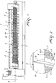
Figure 1 is a partially sectional side elevation view of the pressing unit according to the invention, taken along a longitudinal plane; -
Figure 2 is a highly enlarged-scale view of a detail ofFigure 1 ; -
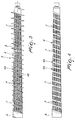
Figure 3 is a side elevation view of the screw feeder of the unit ofFigure 1 ; -
Figure 4 is a side elevation view of the roller of the unit ofFigure 1 . - With particular reference to the cited figures, the reference numeral 1 generally designates a pressing unit, which is preset to remove liquids contained in material of various types.
- It is useful to specify from the outset that in the preferred application, to which reference will be made occasionally in the continuation of the present application, the material from which liquids are extracted by means of the unit 1 is constituted by agroalimentary products of various kinds, supplied to said unit 1 impregnated with water (the liquid to be removed) as a result of previous industrial processes.
- In greater detail, the unit 1 finds an effective application in the sugar sector, in which the treated material is beet pulp (or also leaves or other complementary materials).
- Likewise, the unit 1 is used to remove water or other liquids from other agroalimentary products or byproducts, from fishmeal, alfalfa, waste, biomasses, raw materials and intermediate products of the alternative energy field, or others, without thereby abandoning the protective scope claimed herein.
- At the same time, although the liquid to removed is preferably water, the protection claimed herein is to be understood as extended to the use of the unit 1 also to remove different liquids as a function of the specific practical requirements.
- The unit 1 therefore comprises a
chamber 2 for containing at least onescrew feeder 3; in turn, thescrew feeder 3 comprises aroller 4, which rotates about its own longitudinal axis A, and ahelical element 5, which is wound in a spiral around theroller 4. - The
chamber 2 is affected by an intake port for introducing the material to be pressed and by a discharge port for the pressed material, so as to define a forcedpressing path 6 comprised between thechamber 2 and thescrew feeder 3. - For the sake of simplicity, the ports are not shown in the accompanying figures but can be simple nozzles or openings, provided along the
chamber 2 and preferably (but not exclusively) facing end regions of theroller 4, so as to define apath 6 that is extended substantially along the entirety ofsuch roller 4, maximizing the material pressing and expressing capabilities. - According to substantially known methods, it is specified therefore that while the
screw feeder 3 rotates about the axis A it propels the material along the forcedpath 6 around theroller 4, and this material is forced to assume a progressively decreasing useful volume on at least one segment of adequate length of the roller 4 (and in the manners that will be described for example in the paragraphs that follow). This allows indeed to obtain the desired pressing of the material and therefore the removal of at least part of the water (or other liquids) contained therein. - According to the invention, the lateral surface of the
roller 4, which is at least partially hollow, comprises afirst portion 4a that has a helical extension around the axis A and has a plurality ofholes 7 in order to allow the evacuation of the liquids progressively removed from the material during its advancement along thepath 6. Furthermore, the lateral surface of theroller 4 comprises asecond portion 4b, which also has a helical extension around the axis A and is complementary to thefirst portion 4a. Thesecond portion 4b instead has a continuous non-perforated shape and indeed thehelical element 5 is wound around theroller 4 at this second portion. - In other words, in practice, as also shown clearly by the accompanying figures, the lateral surface of the roller 4 (the one that in practice delimits the
path 6, together with thechamber 2 and the helical element 5) comprises twoportions - By way of the different provision of the two
portions first portion 4a indeed faces the path 6) and, at the same time, a high mechanical strength of thescrew feeder 3, since thehelical element 5 is fixed to theroller 4 at a continuous non-perforated area defined by thesecond portion 4b. - In particular, the
helical element 5 is welded to theroller 4 at thesecond portion 4b, and indeed the choice to keep thesecond portion 4b of the lateral surface of theroller 4 continuous and withoutholes 7 ensures optimum welding, avoiding or at least reducing the risk of cracks and failures, during the normal operation of the unit 1 and/or in case of abnormal stresses, possibly of excessive intensity. - It is specified that preferably but not exclusively both the
roller 4 and thechamber 2 are made of metal plate. - It should be noted that versions of the unit 1 that provide for evacuation of the water only through the
first portion 4a are considered to be comprised within the protective scope provided herein. - However, in the preferred constructive solution, which ensures maximum effectiveness in water evacuation and removal, at least the side walls of the
chamber 2, interposed between the ports, have a plurality of orifices, so as to ensure the evacuation of the liquids progressively removed from the material during its advancement along thepath 6 through said orifices as well. - As a whole, therefore, the water can abandon the
path 6 both through theholes 7 in thefirst portion 4a and through the orifices along thechamber 2. - In a possible constructive solution, the
roller 4 has a substantially cylindrical shape, while thehelical element 5 has a pitch that at least partially decreases (on at least one segment of the roller 5) if measured along thepath 6 from the intake port to the discharge port. This choice allows to obtain the progressive reduction of the volume available to the material during its advancement along the forcedpath 6 in order to obtain, as already anticipated, the pressing of such material. - Likewise, the protective scope claimed herein includes a second constructive solution, in which the
roller 4 has a substantially conical shape, with a progressively increasing transverse cross-section, if measured along thepath 6 from the intake port to the discharge port. In this second solution, thehelical element 5 therefore has an at least partially constant pitch (on at least one segment of the roller 5) or even a slightly decreasing pitch, if measured along thepath 6 from the intake port to the discharge port, achieving again the progressive reduction of the volume available to the material during its advancement along the forcedpath 6. - Resorting to different geometrical choices for the shape of the
roller 4 and the pitch of thehelical element 5, which are constituted by a combination of the two cited above (partially conical and partiallycylindrical roller 4, generically variable pitch) or by yet others, without thereby abandoning the protective scope claimed herein, is not excluded. - With further reference to the possible geometric choices for the unit 1 according to the invention,
chambers 2 having a conical or cylindrical shape, in any case shaped substantially complementarily to the shape and transverse space occupation of thehelical element 5, so as to delimit fully thepath 6, are conveniently adopted. - In an embodiment of considerable practical interest, the
chamber 2 accommodates twoscrew feeders 3, each of which comprises arespective roller 4 and a correspondinghelical element 5. - In this solution, which usefully allows to process a larger quantity of material substantially with the same longitudinal space occupation of the unit 1, the
rollers 4 are substantially side by side and delimit, with thehelical elements 5 and thechamber 2, a single forcedpath 6. Optionally, the twoscrew feeders 3 can be arranged so that the turns of thehelical element 5 of onescrew feeder 3 enter, during rotation, the space comprised between two consecutive turns of thehelical element 5 of theother screw feeder 3, and viceversa. - Furthermore, the provision of units 1 according to the invention in which the
same chamber 2 accommodates three ormore screw feeders 3 is not excluded. - Conveniently, and as a function of the specific requirements of application, the axis A of the roller 4 (of each roller 4) has an orientation selectively among a horizontal orientation, a vertical orientation and an inclined orientation (i.e., forming an angle comprised between 0° and 90° with the horizontal plane on which the entire unit 1 rests).
- In a first practical option, the
roller 4 is constituted substantially by a shaft, which rotates about the axis A and is internally hollow, so as to define an internal duct, which is indeed connected to thepath 6 through theholes 7, for the evacuation of the liquids removed from the material. In other words, in this option the liquid expressed from the material that passes through theholes 7 flows outside the unit 1 through the duct (arranged along the axis A) that is defined inside the shaft. - In a second practical option, which ensures greater solidity to the structure, the
roller 4 is instead constituted substantially by a sleeve for the coaxial covering of a shaft, which rotates about the axis A. - In this option, an interspace is defined between the sleeve and the shaft and is connected to the
path 6 through theholes 7 in order to evacuate the liquids removed from the material (i.e., performing the role that in the other practical option is assigned to the internal duct of the shaft). - Advantageously, the dimensional and geometric parameters of the helical shape of the
portions roller 4 correspond to the material that is intended to pass through the forcedpath 6 and/or to the desired residual liquid content present in the material at the discharge port. - In other words, during design it is possible to choose the inclination of the helical shape, as well as the width of the two
portions first portion 4b (and therefore of the area intended for water evacuation) as well as the shape and dimensions of the welding area and of thehelical element 5 proper, which evidently depend on the geometric choices made for thesecond portion 4b. - Operation of the pressing unit according to the invention is as follows.
- As already noted, the material to be pressed can be introduced in the
chamber 2 through the intake port, which leads directly to the forcedpath 6, which is delimited by thescrew feeder 3 and by thechamber 2 proper. - By way of adequate geometric choices, while the material is pushed by the
screw feeder 3 toward the discharge port, the useful volume offered by thepath 6 decreases and therefore the desired expressing of the material is obtained. - The water (or other liquid) that is removed progressively can then abandon the
chamber 2 through theholes 7 provided along thefirst portion 4a of the lateral surface of theroller 4 and preferably also through the orifices defined along the side walls of thechamber 2. - The large filtering area available to the water ensures extremely high draining efficiencies and therefore better performance, which is assuredly of interest for users.
- At the same time, the choice to weld or otherwise fix the
helical element 5 to theroller 4 at thesecond portion 4b, which is not perforated, of its lateral surface ensures high mechanical strength, overcoming the problems of the background art, in which the helical elements welded to the perforated metal plates are subject to cracks (indeed at the weld) in case of abnormal mechanical stresses or frictions on the helical elements, with consequent failure of the shaft. - Partial perforation (only on the
second portion 4b) therefore allows the unit 1 to achieve a high increase in reliability without reducing the draining effect, since the area offered for draining (composed by thefirst portion 4a and preferably also by the side walls of the chamber 2) is in any case maximum. - The higher mechanical reliability of the
roller 4 further allows to utilize its potential more: for example, it is possible to reduce the rotation rate and increase the final content of dry substance in the pressed material, at the same time reducing machine downtimes, as well as maintenance interventions and inspections. - Finally, it should be noted that the advantages described above are achieved with a solution that can be obtained with low costs, further confirming the extreme practical interest of the invention.
- In practice it has been found that the pressing unit according to the invention achieves fully the intended aim, since by adopting a roller that has a first portion with a helical shape provided with a plurality of holes and a second helical portion that is complementary to the first portion and is not perforated and around which the helical element is wound it is possible to achieve a high effectiveness in water removal without renouncing high mechanical strength.
- The invention thus conceived is susceptible of numerous modifications and variations, all of which are within the scope of the appended claims; all the details may further be replaced with other technically equivalent elements.
- In the examples of embodiment shown, individual characteristics, given in relation to specific examples, may actually be interchanged with other different characteristics that exist in other exemplary embodiments.
- In practice, the materials used, as well as the dimensions, may be any according to requirements and to the state of the art.
- Where technical features mentioned in any claim are followed by reference signs, those reference signs have been included for the sole purpose of increasing the intelligibility of the claims and accordingly such reference signs do not have any limiting effect on the interpretation of each element identified by way of example by such reference signs.
Claims (11)
- A pressing unit for removing liquids contained in material of various types, comprising a chamber (2) for containing at least one screw feeder (3), said screw feeder (3) comprising a roller (4) that rotates about its own longitudinal axis (A) and a helical element (5) that is wound in a spiral around said roller (4), said chamber (2) being affected by an intake port for introducing the material to be pressed and by a discharge port for the pressed material, in order to define a forced pressing path (6) comprised between said chamber (2) and said at least one screw feeder (3), characterized in that the lateral surface of said roller (4), which is at least partially hollow, comprises a first portion (4a), which has a helical extension around said axis (A) and is provided with a plurality of holes (7), for the evacuation of the liquids removed progressively from the material during its advancement along said path (6), and a second portion (4b), which has a helical extension around said axis (A) and is complementary to said first portion (4a), said helical element (5) being wound around said roller (4) at said second portion (4b), which has a continuous, non-perforated shape.
- The pressing unit according to claim 1, characterized in that said helical element (5) is welded onto said roller (4) at said second portion (4b).
- The pressing unit according to claim 1 or 2, characterized in that at least the side walls of said chamber (2), which are interposed between said ports, have a plurality of orifices, for the evacuation of the liquids removed progressively from the material during its advancement along said path (6).
- The pressing unit according to one or more of the preceding claims, characterized in that said roller (4) has a substantially cylindrical shape, said helical element (5) having a pitch that decreases at least partially, measured along said path (6) from said intake port to said discharge port, for the progressive reduction of the volume available to the material during its advancement along said forced path (6).
- The pressing unit according to one or more of claims 1 to 3, characterized in that said roller (4) has a substantially conical shape, with a progressively increasing transverse cross-section, measured along said path (6) from said intake port to said discharge port, said helical element (5) having a pitch that is at least partially constant, measured along said path (6) from said intake port to said discharge port, for the progressive reduction of the volume available to the material during its advancement along said forced path (6).
- The pressing unit according to one or more of the preceding claims, characterized in that said chamber (2) has a conical or cylindrical shape that is substantially complementary to the shape and transverse space occupation of said at least one helical element (5).
- The pressing unit according to one or more of the preceding claims, characterized in that said chamber (2) accommodates two of said screw feeders (3), each one of said screw feeders (3) comprising a respective said roller (4) and a corresponding said helical element (5), said shafts being substantially side by side and delimiting, with said helical elements (5) and said chamber (2), said forced path (6).
- The pressing unit according to one or more of the preceding claims, characterized in that said axis (A) of said at least one roller (4) has an orientation chosen among a horizontal orientation, a vertical orientation and an inclined orientation.
- The pressing unit according to one or more of the preceding claims, characterized in that said roller (4) is constituted substantially by a shaft that rotates about said axis (A) and is internally hollow, in order to define an internal duct that is connected to said path (6) through said holes (7) for evacuating the liquids removed from the material.
- The pressing unit according to one or more of claims 1 to 8, characterized in that said roller (4) is constituted substantially by a sleeve for the coaxial covering of a shaft, which rotates about said axis (A), an interspace being defined between said sleeve and said shaft and being connected to said path (6) through said holes (7), for the evacuation of the liquids removed from the material.
- The pressing unit according to one or more of the preceding claims, characterized in that the dimensional and geometric parameters of the helical shape of said portions (4a, 4b) of said lateral surface correspond to the material that is intended to move along said forced path (6) and/or to the desired residual liquid content that is present in the material at said discharge port.
Priority Applications (2)
| Application Number | Priority Date | Filing Date | Title |
|---|---|---|---|
| EP16425028.4A EP3228444B1 (en) | 2016-04-04 | 2016-04-04 | Pressing unit for removing liquids |
| ES16425028T ES2905309T3 (en) | 2016-04-04 | 2016-04-04 | Pressing unit to remove liquids |
Applications Claiming Priority (1)
| Application Number | Priority Date | Filing Date | Title |
|---|---|---|---|
| EP16425028.4A EP3228444B1 (en) | 2016-04-04 | 2016-04-04 | Pressing unit for removing liquids |
Publications (2)
| Publication Number | Publication Date |
|---|---|
| EP3228444A1 true EP3228444A1 (en) | 2017-10-11 |
| EP3228444B1 EP3228444B1 (en) | 2021-12-22 |
Family
ID=56092861
Family Applications (1)
| Application Number | Title | Priority Date | Filing Date |
|---|---|---|---|
| EP16425028.4A Active EP3228444B1 (en) | 2016-04-04 | 2016-04-04 | Pressing unit for removing liquids |
Country Status (2)
| Country | Link |
|---|---|
| EP (1) | EP3228444B1 (en) |
| ES (1) | ES2905309T3 (en) |
Cited By (1)
| Publication number | Priority date | Publication date | Assignee | Title |
|---|---|---|---|---|
| EP4046788A1 (en) * | 2021-02-19 | 2022-08-24 | Babbini S.P.A. | Pressing apparatus |
Citations (5)
| Publication number | Priority date | Publication date | Assignee | Title |
|---|---|---|---|---|
| GB191126750A (en) * | 1911-11-29 | 1912-03-14 | Robert Hanson | Apparatus for Drying or Expressing Liquid from Tan Waste and other Plastic Materials. |
| EP0930152A1 (en) * | 1998-01-15 | 1999-07-21 | Lionello Babbini | Screw press for dehydrating products containing moisture |
| WO2003031166A1 (en) * | 2001-10-10 | 2003-04-17 | Stord International Ass | A screw press and a method of pressing a liquid-containing substance as well as use thereof |
| US20040035804A1 (en) * | 2000-08-04 | 2004-02-26 | Rudolf Bischof | Separating device for separating fluids from solids and use thereof |
| WO2004080704A1 (en) * | 2003-03-14 | 2004-09-23 | Atlas-Stord Denmark A/S | A screw press having a cylindrical portion |
-
2016
- 2016-04-04 ES ES16425028T patent/ES2905309T3/en active Active
- 2016-04-04 EP EP16425028.4A patent/EP3228444B1/en active Active
Patent Citations (5)
| Publication number | Priority date | Publication date | Assignee | Title |
|---|---|---|---|---|
| GB191126750A (en) * | 1911-11-29 | 1912-03-14 | Robert Hanson | Apparatus for Drying or Expressing Liquid from Tan Waste and other Plastic Materials. |
| EP0930152A1 (en) * | 1998-01-15 | 1999-07-21 | Lionello Babbini | Screw press for dehydrating products containing moisture |
| US20040035804A1 (en) * | 2000-08-04 | 2004-02-26 | Rudolf Bischof | Separating device for separating fluids from solids and use thereof |
| WO2003031166A1 (en) * | 2001-10-10 | 2003-04-17 | Stord International Ass | A screw press and a method of pressing a liquid-containing substance as well as use thereof |
| WO2004080704A1 (en) * | 2003-03-14 | 2004-09-23 | Atlas-Stord Denmark A/S | A screw press having a cylindrical portion |
Cited By (1)
| Publication number | Priority date | Publication date | Assignee | Title |
|---|---|---|---|---|
| EP4046788A1 (en) * | 2021-02-19 | 2022-08-24 | Babbini S.P.A. | Pressing apparatus |
Also Published As
| Publication number | Publication date |
|---|---|
| ES2905309T3 (en) | 2022-04-07 |
| EP3228444B1 (en) | 2021-12-22 |
Similar Documents
| Publication | Publication Date | Title |
|---|---|---|
| US2355091A (en) | Apparatus for the treatment and removal of chemicals from cooked or digested fiber pulp | |
| CN103946017B (en) | Fly press | |
| WO2001026776A1 (en) | Rotary type compressive filtrating machine | |
| KR20150114000A (en) | Screw press for the treatment of contaminants | |
| JP2010099643A (en) | Compression deliquoring device | |
| EP3228444B1 (en) | Pressing unit for removing liquids | |
| US7461591B2 (en) | Screw press for squeezing out fibrous material | |
| JP2011235265A (en) | Screen residue separating and dewatering machine | |
| EP0930152A1 (en) | Screw press for dehydrating products containing moisture | |
| KR100940388B1 (en) | Screw dehydrator and dry apparatus using the same | |
| JP4152179B2 (en) | Screw press and dewatering method | |
| JP6183622B2 (en) | Solid recovery system for drum type concentrator | |
| EP1990181A2 (en) | Press for mechanical dehydration | |
| US10118358B2 (en) | Screw press for separation of liquid from bulk materials | |
| KR20070081993A (en) | Electroosmotic dehydrator | |
| JP2005501723A (en) | Press machine for dehumidification of wet materials, especially untreated waste | |
| US1769658A (en) | Press for the treatment of moist materials | |
| EP4046788A1 (en) | Pressing apparatus | |
| JP2011020080A (en) | Apparatus for separating and dehydrating sewage sludge | |
| JP4493030B2 (en) | Filtration device | |
| RU2687116C2 (en) | Screw press | |
| JP2001321989A (en) | Double screw type screw press | |
| JP6803612B2 (en) | Pressurized rotary plate type solid-liquid separator | |
| JP2007105588A (en) | Filter apparatus | |
| CN111617526A (en) | Rotary drum type solid-liquid separator |
Legal Events
| Date | Code | Title | Description |
|---|---|---|---|
| PUAI | Public reference made under article 153(3) epc to a published international application that has entered the european phase |
Free format text: ORIGINAL CODE: 0009012 |
|
| STAA | Information on the status of an ep patent application or granted ep patent |
Free format text: STATUS: THE APPLICATION HAS BEEN PUBLISHED |
|
| AK | Designated contracting states |
Kind code of ref document: A1 Designated state(s): AL AT BE BG CH CY CZ DE DK EE ES FI FR GB GR HR HU IE IS IT LI LT LU LV MC MK MT NL NO PL PT RO RS SE SI SK SM TR |
|
| AX | Request for extension of the european patent |
Extension state: BA ME |
|
| STAA | Information on the status of an ep patent application or granted ep patent |
Free format text: STATUS: REQUEST FOR EXAMINATION WAS MADE |
|
| 17P | Request for examination filed |
Effective date: 20180403 |
|
| RBV | Designated contracting states (corrected) |
Designated state(s): AL AT BE BG CH CY CZ DE DK EE ES FI FR GB GR HR HU IE IS IT LI LT LU LV MC MK MT NL NO PL PT RO RS SE SI SK SM TR |
|
| GRAP | Despatch of communication of intention to grant a patent |
Free format text: ORIGINAL CODE: EPIDOSNIGR1 |
|
| STAA | Information on the status of an ep patent application or granted ep patent |
Free format text: STATUS: GRANT OF PATENT IS INTENDED |
|
| INTG | Intention to grant announced |
Effective date: 20210617 |
|
| GRAS | Grant fee paid |
Free format text: ORIGINAL CODE: EPIDOSNIGR3 |
|
| GRAA | (expected) grant |
Free format text: ORIGINAL CODE: 0009210 |
|
| STAA | Information on the status of an ep patent application or granted ep patent |
Free format text: STATUS: THE PATENT HAS BEEN GRANTED |
|
| AK | Designated contracting states |
Kind code of ref document: B1 Designated state(s): AL AT BE BG CH CY CZ DE DK EE ES FI FR GB GR HR HU IE IS IT LI LT LU LV MC MK MT NL NO PL PT RO RS SE SI SK SM TR |
|
| REG | Reference to a national code |
Ref country code: GB Ref legal event code: FG4D |
|
| REG | Reference to a national code |
Ref country code: CH Ref legal event code: EP |
|
| REG | Reference to a national code |
Ref country code: DE Ref legal event code: R096 Ref document number: 602016067578 Country of ref document: DE |
|
| REG | Reference to a national code |
Ref country code: AT Ref legal event code: REF Ref document number: 1456822 Country of ref document: AT Kind code of ref document: T Effective date: 20220115 |
|
| REG | Reference to a national code |
Ref country code: IE Ref legal event code: FG4D |
|
| REG | Reference to a national code |
Ref country code: ES Ref legal event code: FG2A Ref document number: 2905309 Country of ref document: ES Kind code of ref document: T3 Effective date: 20220407 |
|
| REG | Reference to a national code |
Ref country code: LT Ref legal event code: MG9D |
|
| PG25 | Lapsed in a contracting state [announced via postgrant information from national office to epo] |
Ref country code: RS Free format text: LAPSE BECAUSE OF FAILURE TO SUBMIT A TRANSLATION OF THE DESCRIPTION OR TO PAY THE FEE WITHIN THE PRESCRIBED TIME-LIMIT Effective date: 20211222 Ref country code: LT Free format text: LAPSE BECAUSE OF FAILURE TO SUBMIT A TRANSLATION OF THE DESCRIPTION OR TO PAY THE FEE WITHIN THE PRESCRIBED TIME-LIMIT Effective date: 20211222 Ref country code: FI Free format text: LAPSE BECAUSE OF FAILURE TO SUBMIT A TRANSLATION OF THE DESCRIPTION OR TO PAY THE FEE WITHIN THE PRESCRIBED TIME-LIMIT Effective date: 20211222 Ref country code: BG Free format text: LAPSE BECAUSE OF FAILURE TO SUBMIT A TRANSLATION OF THE DESCRIPTION OR TO PAY THE FEE WITHIN THE PRESCRIBED TIME-LIMIT Effective date: 20220322 |
|
| REG | Reference to a national code |
Ref country code: NL Ref legal event code: MP Effective date: 20211222 |
|
| REG | Reference to a national code |
Ref country code: AT Ref legal event code: MK05 Ref document number: 1456822 Country of ref document: AT Kind code of ref document: T Effective date: 20211222 |
|
| REG | Reference to a national code |
Ref country code: NO Ref legal event code: T2 Effective date: 20211222 |
|
| PG25 | Lapsed in a contracting state [announced via postgrant information from national office to epo] |
Ref country code: SE Free format text: LAPSE BECAUSE OF FAILURE TO SUBMIT A TRANSLATION OF THE DESCRIPTION OR TO PAY THE FEE WITHIN THE PRESCRIBED TIME-LIMIT Effective date: 20211222 Ref country code: LV Free format text: LAPSE BECAUSE OF FAILURE TO SUBMIT A TRANSLATION OF THE DESCRIPTION OR TO PAY THE FEE WITHIN THE PRESCRIBED TIME-LIMIT Effective date: 20211222 Ref country code: HR Free format text: LAPSE BECAUSE OF FAILURE TO SUBMIT A TRANSLATION OF THE DESCRIPTION OR TO PAY THE FEE WITHIN THE PRESCRIBED TIME-LIMIT Effective date: 20211222 Ref country code: GR Free format text: LAPSE BECAUSE OF FAILURE TO SUBMIT A TRANSLATION OF THE DESCRIPTION OR TO PAY THE FEE WITHIN THE PRESCRIBED TIME-LIMIT Effective date: 20220323 |
|
| PG25 | Lapsed in a contracting state [announced via postgrant information from national office to epo] |
Ref country code: NL Free format text: LAPSE BECAUSE OF FAILURE TO SUBMIT A TRANSLATION OF THE DESCRIPTION OR TO PAY THE FEE WITHIN THE PRESCRIBED TIME-LIMIT Effective date: 20211222 |
|
| PG25 | Lapsed in a contracting state [announced via postgrant information from national office to epo] |
Ref country code: SM Free format text: LAPSE BECAUSE OF FAILURE TO SUBMIT A TRANSLATION OF THE DESCRIPTION OR TO PAY THE FEE WITHIN THE PRESCRIBED TIME-LIMIT Effective date: 20211222 Ref country code: SK Free format text: LAPSE BECAUSE OF FAILURE TO SUBMIT A TRANSLATION OF THE DESCRIPTION OR TO PAY THE FEE WITHIN THE PRESCRIBED TIME-LIMIT Effective date: 20211222 Ref country code: RO Free format text: LAPSE BECAUSE OF FAILURE TO SUBMIT A TRANSLATION OF THE DESCRIPTION OR TO PAY THE FEE WITHIN THE PRESCRIBED TIME-LIMIT Effective date: 20211222 Ref country code: PT Free format text: LAPSE BECAUSE OF FAILURE TO SUBMIT A TRANSLATION OF THE DESCRIPTION OR TO PAY THE FEE WITHIN THE PRESCRIBED TIME-LIMIT Effective date: 20220422 Ref country code: EE Free format text: LAPSE BECAUSE OF FAILURE TO SUBMIT A TRANSLATION OF THE DESCRIPTION OR TO PAY THE FEE WITHIN THE PRESCRIBED TIME-LIMIT Effective date: 20211222 Ref country code: CZ Free format text: LAPSE BECAUSE OF FAILURE TO SUBMIT A TRANSLATION OF THE DESCRIPTION OR TO PAY THE FEE WITHIN THE PRESCRIBED TIME-LIMIT Effective date: 20211222 |
|
| PGFP | Annual fee paid to national office [announced via postgrant information from national office to epo] |
Ref country code: GB Payment date: 20220531 Year of fee payment: 7 |
|
| PG25 | Lapsed in a contracting state [announced via postgrant information from national office to epo] |
Ref country code: PL Free format text: LAPSE BECAUSE OF FAILURE TO SUBMIT A TRANSLATION OF THE DESCRIPTION OR TO PAY THE FEE WITHIN THE PRESCRIBED TIME-LIMIT Effective date: 20211222 Ref country code: AT Free format text: LAPSE BECAUSE OF FAILURE TO SUBMIT A TRANSLATION OF THE DESCRIPTION OR TO PAY THE FEE WITHIN THE PRESCRIBED TIME-LIMIT Effective date: 20211222 |
|
| REG | Reference to a national code |
Ref country code: DE Ref legal event code: R097 Ref document number: 602016067578 Country of ref document: DE |
|
| PG25 | Lapsed in a contracting state [announced via postgrant information from national office to epo] |
Ref country code: IS Free format text: LAPSE BECAUSE OF FAILURE TO SUBMIT A TRANSLATION OF THE DESCRIPTION OR TO PAY THE FEE WITHIN THE PRESCRIBED TIME-LIMIT Effective date: 20220422 |
|
| PLBE | No opposition filed within time limit |
Free format text: ORIGINAL CODE: 0009261 |
|
| STAA | Information on the status of an ep patent application or granted ep patent |
Free format text: STATUS: NO OPPOSITION FILED WITHIN TIME LIMIT |
|
| PG25 | Lapsed in a contracting state [announced via postgrant information from national office to epo] |
Ref country code: DK Free format text: LAPSE BECAUSE OF FAILURE TO SUBMIT A TRANSLATION OF THE DESCRIPTION OR TO PAY THE FEE WITHIN THE PRESCRIBED TIME-LIMIT Effective date: 20211222 Ref country code: AL Free format text: LAPSE BECAUSE OF FAILURE TO SUBMIT A TRANSLATION OF THE DESCRIPTION OR TO PAY THE FEE WITHIN THE PRESCRIBED TIME-LIMIT Effective date: 20211222 |
|
| 26N | No opposition filed |
Effective date: 20220923 |
|
| REG | Reference to a national code |
Ref country code: CH Ref legal event code: PL |
|
| REG | Reference to a national code |
Ref country code: BE Ref legal event code: MM Effective date: 20220430 |
|
| PG25 | Lapsed in a contracting state [announced via postgrant information from national office to epo] |
Ref country code: MC Free format text: LAPSE BECAUSE OF FAILURE TO SUBMIT A TRANSLATION OF THE DESCRIPTION OR TO PAY THE FEE WITHIN THE PRESCRIBED TIME-LIMIT Effective date: 20211222 Ref country code: LU Free format text: LAPSE BECAUSE OF NON-PAYMENT OF DUE FEES Effective date: 20220404 Ref country code: LI Free format text: LAPSE BECAUSE OF NON-PAYMENT OF DUE FEES Effective date: 20220430 Ref country code: CH Free format text: LAPSE BECAUSE OF NON-PAYMENT OF DUE FEES Effective date: 20220430 |
|
| PG25 | Lapsed in a contracting state [announced via postgrant information from national office to epo] |
Ref country code: SI Free format text: LAPSE BECAUSE OF FAILURE TO SUBMIT A TRANSLATION OF THE DESCRIPTION OR TO PAY THE FEE WITHIN THE PRESCRIBED TIME-LIMIT Effective date: 20211222 Ref country code: BE Free format text: LAPSE BECAUSE OF NON-PAYMENT OF DUE FEES Effective date: 20220430 |
|
| REG | Reference to a national code |
Ref country code: FR Ref legal event code: PLFP Year of fee payment: 8 |
|
| PG25 | Lapsed in a contracting state [announced via postgrant information from national office to epo] |
Ref country code: IE Free format text: LAPSE BECAUSE OF NON-PAYMENT OF DUE FEES Effective date: 20220404 |
|
| PGFP | Annual fee paid to national office [announced via postgrant information from national office to epo] |
Ref country code: NO Payment date: 20230417 Year of fee payment: 8 Ref country code: IT Payment date: 20230406 Year of fee payment: 8 Ref country code: FR Payment date: 20230413 Year of fee payment: 8 Ref country code: ES Payment date: 20230505 Year of fee payment: 8 Ref country code: DE Payment date: 20230414 Year of fee payment: 8 |
|
| GBPC | Gb: european patent ceased through non-payment of renewal fee |
Effective date: 20230404 |
|
| PG25 | Lapsed in a contracting state [announced via postgrant information from national office to epo] |
Ref country code: GB Free format text: LAPSE BECAUSE OF NON-PAYMENT OF DUE FEES Effective date: 20230404 |
|
| PG25 | Lapsed in a contracting state [announced via postgrant information from national office to epo] |
Ref country code: GB Free format text: LAPSE BECAUSE OF NON-PAYMENT OF DUE FEES Effective date: 20230404 |
|
| PG25 | Lapsed in a contracting state [announced via postgrant information from national office to epo] |
Ref country code: HU Free format text: LAPSE BECAUSE OF FAILURE TO SUBMIT A TRANSLATION OF THE DESCRIPTION OR TO PAY THE FEE WITHIN THE PRESCRIBED TIME-LIMIT; INVALID AB INITIO Effective date: 20160404 |
|
| PG25 | Lapsed in a contracting state [announced via postgrant information from national office to epo] |
Ref country code: MK Free format text: LAPSE BECAUSE OF FAILURE TO SUBMIT A TRANSLATION OF THE DESCRIPTION OR TO PAY THE FEE WITHIN THE PRESCRIBED TIME-LIMIT Effective date: 20211222 Ref country code: CY Free format text: LAPSE BECAUSE OF FAILURE TO SUBMIT A TRANSLATION OF THE DESCRIPTION OR TO PAY THE FEE WITHIN THE PRESCRIBED TIME-LIMIT Effective date: 20211222 |