EP3228293B1 - Unterstützte hebevorrichtungen für ein kinderbett - Google Patents
Unterstützte hebevorrichtungen für ein kinderbett Download PDFInfo
- Publication number
- EP3228293B1 EP3228293B1 EP17169129.8A EP17169129A EP3228293B1 EP 3228293 B1 EP3228293 B1 EP 3228293B1 EP 17169129 A EP17169129 A EP 17169129A EP 3228293 B1 EP3228293 B1 EP 3228293B1
- Authority
- EP
- European Patent Office
- Prior art keywords
- actuation
- keyway
- keyway plate
- roll
- plate
- Prior art date
- Legal status (The legal status is an assumption and is not a legal conclusion. Google has not performed a legal analysis and makes no representation as to the accuracy of the status listed.)
- Active
Links
Images


Classifications
-
- A—HUMAN NECESSITIES
- A61—MEDICAL OR VETERINARY SCIENCE; HYGIENE
- A61G—TRANSPORT, PERSONAL CONVEYANCES, OR ACCOMMODATION SPECIALLY ADAPTED FOR PATIENTS OR DISABLED PERSONS; OPERATING TABLES OR CHAIRS; CHAIRS FOR DENTISTRY; FUNERAL DEVICES
- A61G1/00—Stretchers
- A61G1/04—Parts, details or accessories, e.g. head-, foot-, or like rests specially adapted for stretchers
- A61G1/052—Struts, spars or legs
- A61G1/056—Swivelling legs
- A61G1/0562—Swivelling legs independently foldable, i.e. at least part of the leg folding movement is not simultaneous
-
- A—HUMAN NECESSITIES
- A61—MEDICAL OR VETERINARY SCIENCE; HYGIENE
- A61G—TRANSPORT, PERSONAL CONVEYANCES, OR ACCOMMODATION SPECIALLY ADAPTED FOR PATIENTS OR DISABLED PERSONS; OPERATING TABLES OR CHAIRS; CHAIRS FOR DENTISTRY; FUNERAL DEVICES
- A61G1/00—Stretchers
- A61G1/013—Stretchers foldable or collapsible
-
- A—HUMAN NECESSITIES
- A61—MEDICAL OR VETERINARY SCIENCE; HYGIENE
- A61G—TRANSPORT, PERSONAL CONVEYANCES, OR ACCOMMODATION SPECIALLY ADAPTED FOR PATIENTS OR DISABLED PERSONS; OPERATING TABLES OR CHAIRS; CHAIRS FOR DENTISTRY; FUNERAL DEVICES
- A61G1/00—Stretchers
- A61G1/02—Stretchers with wheels
- A61G1/0206—Stretchers with wheels characterised by the number of supporting wheels if stretcher is extended
- A61G1/0212—2 pairs having wheels within a pair on the same position in longitudinal direction, e.g. on the same axis
-
- A—HUMAN NECESSITIES
- A61—MEDICAL OR VETERINARY SCIENCE; HYGIENE
- A61G—TRANSPORT, PERSONAL CONVEYANCES, OR ACCOMMODATION SPECIALLY ADAPTED FOR PATIENTS OR DISABLED PERSONS; OPERATING TABLES OR CHAIRS; CHAIRS FOR DENTISTRY; FUNERAL DEVICES
- A61G1/00—Stretchers
- A61G1/02—Stretchers with wheels
- A61G1/025—Stretchers with wheels having auxiliary wheels, e.g. wheels not touching the ground in extended position
- A61G1/0256—Stretchers with wheels having auxiliary wheels, e.g. wheels not touching the ground in extended position having wheels which support exclusively if stretcher is in low position, e.g. on the folded legs
-
- A—HUMAN NECESSITIES
- A61—MEDICAL OR VETERINARY SCIENCE; HYGIENE
- A61G—TRANSPORT, PERSONAL CONVEYANCES, OR ACCOMMODATION SPECIALLY ADAPTED FOR PATIENTS OR DISABLED PERSONS; OPERATING TABLES OR CHAIRS; CHAIRS FOR DENTISTRY; FUNERAL DEVICES
- A61G1/00—Stretchers
- A61G1/02—Stretchers with wheels
- A61G1/0237—Stretchers with wheels having at least one swivelling wheel, e.g. castors
- A61G1/0243—Stretchers with wheels having at least one swivelling wheel, e.g. castors with lockable swivel action, e.g. fixing castor in certain direction
-
- A—HUMAN NECESSITIES
- A61—MEDICAL OR VETERINARY SCIENCE; HYGIENE
- A61G—TRANSPORT, PERSONAL CONVEYANCES, OR ACCOMMODATION SPECIALLY ADAPTED FOR PATIENTS OR DISABLED PERSONS; OPERATING TABLES OR CHAIRS; CHAIRS FOR DENTISTRY; FUNERAL DEVICES
- A61G1/00—Stretchers
- A61G1/02—Stretchers with wheels
- A61G1/025—Stretchers with wheels having auxiliary wheels, e.g. wheels not touching the ground in extended position
- A61G1/0262—Stretchers with wheels having auxiliary wheels, e.g. wheels not touching the ground in extended position having loading wheels situated in the front during loading
Definitions
- the present disclosure is generally related to emergency cots, and is specifically directed to lift assist mechanisms for roll-in cots and roll-in cots having assisted lifting devices for articulating a portion of a stretcher.
- Such emergency cots may be designed to transport and load patients into an ambulance.
- US4970737 discloses an adjustable hospital and nursing home bed, having a three-part support frame for mattresses, the head, middle and foot frame portions of which are pivotably connected to one another via pivot shafts.
- Conventional cot designs may include a variety of adjustments to improve patient comfort or to position the patent for improved medical treatment. However, some of these adjustments may be difficult for the caregiver to adjust, or may not provide the care giver with enough flexibility in positioning the cot as desired to address the particular patient's needs.
- roll-in cots having various repositioning elements may be desired.
- Described herein is a versatile multipurpose roll-in emergency cot which may provide improved adjustability of components of the cot while maintaining the cot weight, complexity, and cost.
- a roll-in cot includes a support frame, a stretcher coupled to the support frame, where the stretcher has a torso portion coupled to a hips portion with a hinge, and a lift assist mechanism coupled to the support frame and the torso portion of the stretcher.
- the lift assist mechanism includes a force application member having an actuation element, an actuation mechanism having a first grasp handle and a second grasp handle, and a force transmission assembly coupling the first grasp handle and the second grasp handle to the actuation element of the force application member for selective engagement with the actuation element.
- the force transmission assembly includes a first keyway plate coupled to the first grasp handle, a second keyway plate coupled to the second grasp handle, and an actuation pin that selectively applies force to the actuation element of the force application member when selected by one or both of the first keyway plate or the second keyway plate.
- a lift assist mechanism for articulating a portion of a stretcher includes a force application member having an actuation element, an actuation mechanism comprising a first grasp handle and a second grasp handle, and a force transmission assembly.
- the force transmission assembly includes a first keyway plate that is coupled to the first grasp handle, a second keyway plate that is coupled to the second grasp handle, and an actuation pin that extends through both the first keyway plate and the second keyway plate.
- the actuation pin is configured to selectively apply a force to the actuation element.
- the invention is characterised in this aspect in that the first keyway plate and the second keyway plate are both repositionable between a relaxed position and an actuation position in response to a force applied to the first grasp handle and the second grasp handle, and the movement of the first or second keyway plates from the relaxed position to the actuation position brings the actuation pin in or out of contact with the actuation element of the force application member, and the first grasp handle and the second grasp handle are mechanically coupled to the force transmission assembly through a first linkage or a second linkage, respectively.
- a lift assist mechanism includes a force application member having an actuation element, an actuation mechanism having a first grasp handle and a second grasp handle, and a force transmission assembly.
- the force transmission assembly includes a first keyway plate that is coupled to the first grasp handle, a second keyway plate that is coupled to the second grasp handle, and an actuation pin that extends through both the first keyway plate and the second keyway plate.
- the actuation pin selectively applies a force to the actuation element of the force application member.
- the first keyway plate and the second keyway plate are both repositionable between a relaxed position and an actuation position.
- Each of the first keyway plate and the second keyway plate comprise a keyway having an actuation portion and a relief portion, and the first keyway plate and the second keyway plate are located in the actuation position when the actuation pin is positioned proximate to the actuation portion of the keyway.
- a portion of the first keyway plate that contacts the actuation pin as the first keyway plate translates between a relaxed position and the actuation position is transverse to the direction of translation of the first keyway plate.
- Roll-in cots that are used to transport patients may have a variety of repositionable support members that allow the patient to be supported in a variety of positions.
- the repositionable support members of the roll-in cots may be articulated into partially or completely elevated orientations such that the corresponding body portion of the patient is maintained in a partially or completely elevated orientations.
- the roll-in cots may incorporate at least one lift assist mechanism that selectively applies a force to at least one of the repositionable support members so that the repositionable support members can more easily be articulated or repositioned throughout their range of motion.
- the service provider who is assisting the patient on roll-in cot may not have both hands free to actuate the lift assist mechanism.
- Embodiments according to the present disclosure allow the service provider to use one of multiple grasp handles to actuate a single lift assist mechanism, thereby allowing the service provider to actuate the lift assist mechanism with one or two hands that the service provider has free at a particular time.
- the roll-in cot 10 includes a support frame 12 comprising a front end 17, and a back end 19.
- the front end 17 is synonymous with the loading end, i.e., the end of the roll-in cot 10 which is loaded first onto a loading surface.
- the back end 19 is the end of the roll-in cot 10 which is loaded last onto a loading surface.
- the phrase “head end” may be used interchangeably with the phrase “front end,” and the phrase “foot end” may be used interchangeably with the phrase “back end.”
- the phrases “front end” and “back end” are interchangeable.
- the term “patient” refers to any living thing or formerly living thing such as, for example, a human, an animal, a corpse, and the like.
- the roll-in cot 10 also includes a pair of retractable and extendible front legs 20 coupled to the support frame 12, and a pair of retractable and extendible back legs 40 coupled to the support frame 12.
- the roll-in cot 10 may be made from any rigid material such as, for example, metal structures or composite structures.
- the support frame 12, the front legs 20, the back legs 40, or combinations thereof may be made from a carbon fiber and resin structure or a fiberglass and resin structure.
- the roll-in cot 10 may be raised to multiple heights by extending the front legs 20 and/or the back legs 40, or the roll-in cot 10 may be lowered to multiple heights by retracting the front legs 20 and/or the back legs 40.
- front legs 20 and the back legs 40 may comprise front wheels 26 and back wheels 46 which enable the roll-in cot 10 to roll.
- the front wheels 26 and back wheels 46 may be swivel caster wheels or swivel locked wheels. As is described below, as the roll-in cot 10 is raised and/or lowered, the front wheels 26 and back wheels 46 may be synchronized to ensure that the plane of the roll-in cot 10 and the plane of the wheels 26, 46 are substantially parallel.
- the back wheels 46 may each be coupled to a back wheel linkage 47 and the front wheels 26 may each be coupled to a front wheel linkage 27.
- the front wheel linkages 27 and the back wheel linkages 47 may be rotated to control the plane of the wheels 26, 46.
- the roll-in cot 10 includes a stretcher 90 that is positioned along the top of the support frame 12.
- the stretcher 90 may be selectively coupled to the support frame 12 so that the stretcher 90 may be removed from the support structure of the roll-in cot 10, including the support frame 12, the front legs 20, and the rear legs 40.
- the stretcher 90 may further include a mattress positioned on top of the stretcher surfaces, but which is not depicted for clarity of other roll-in cot 10 components.
- the stretcher 90 may include a plurality of portions that are coupled to one another.
- the stretcher 90 includes a torso portion 92, a hip portion 94, and a leg portion 96, which correspond to the torso, hips, and legs, respectively, of a patient positioned on the stretcher 90 in a supine position.
- the torso portion 92, the hip portion 94, and the leg portion 96 may be coupled to one another with a variety of components that provide the desired functional relationship between the torso portion 92, the hip portion 94, and the leg portion 96.
- the torso portion 92 is coupled to the hip portion 94 through a first hinge 93.
- the hip portion 94 is coupled to the leg portion 96 through a second hinge 95.
- the first hinge 93 and the second hinge 95 allow the torso portion 92 and the leg portion 96 to articulate relative to the hip portion 94, respectively.
- the torso portion 92 may be rotated relative to the hip portion 94 so that the torso portion 92 is located in positions corresponding to the patient sitting in an upright, seated orientation.
- the leg portion 96 may be rotated relative to the hip portion 94 so that the leg portion 96 is located in positions corresponding to the patient having inclined legs.
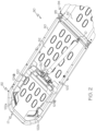
- the stretcher 90 is depicted in a view from below, with components of the roll-in cot 10 removed.
- underside structure of the stretcher 90 may be viewed.
- the stretcher 90 includes a space frame 80 that defines the general exterior dimensions of the stretcher 90 and a support material 82 positioned along interior portions of the space frame 80.
- the stretcher 90 includes at least one lift assist mechanism 100. In the embodiment depicted in FIG.
- the lift assist mechanism 100 is coupled to the torso portion 92 of the stretcher 90 and to the additional structure of the roll-in cot 10 (which is generally depicted in FIG. 1 ).
- Other embodiments of the roll-in cot 10 may incorporate a lift assist mechanism 100 that is coupled to the leg portion 86 (shown in FIG. 1 ) of the stretcher 90.
- the lift assist mechanism provides force that tends to assist in the articulation of the respective portion of the stretcher 90 so that the portion of the stretcher can be easily articulated between elevated and flat configurations.
- the lift assist mechanism 100 includes a force application member 110 (for example, a pressurized gas cylinder) that is adapted to selectively provide a force that tends to extend the force application member 110.
- a force application member 110 for example, a pressurized gas cylinder
- the force application member 110 provides a force that tends to raise the torso portion 92 of the stretcher 90 towards an elevated position relative to the hip portion 94 of the stretcher 90.
- the force application member 100 may provide a force that overcomes at least some of the force associated with the weight of the torso portion 92 of the stretcher 90, and may provide a force that overcomes at least some of the force associated with the weight of the patient's torso positioned proximate to and supported by the torso portion 92 of the stretcher 90.
- the lift assist mechanism 100 also includes an actuation mechanism 120.
- the actuation mechanism 120 includes two grasp handles 122 (i.e., a first grasp handle 122a and a second grasp handle 122b) that are positioned proximate to the space frame 80 at locations proximate to the front end 17 of the roll-in cot 10.
- the stretcher 90 includes clearance within the support material 82 so that a user of the roll-in cot 10 may selectively digitally contact and actuate at least one of the grasp handles 122 when a patient is positioned on the top surface of the stretcher 90.
- the first grasp handle 122a and the second grasp handle 122b are mechanically coupled to a force transmission assembly 130 through a first linkage 124a or a second linkage 124b, respectively.
- the linkages 124 are cable-based systems having a flexible cable that runs along the length of a jacket.
- Examples of apparatuses suitable for use as the linkage 124 include pull cables, push-pull cables, rod-and-ball end mechanical linkages, and the like.
- the force transmission assembly 130 redirects the force imparted from the linkage 124 to actuate the force application member 110, as will be described in greater detail below.
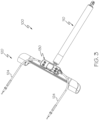
- FIGS. 4 and 5 the actuation mechanism 120 is shown in greater detail, along with the force application member 110 of the lift assist mechanism 100.
- force applied to the grasp handles 122 (shown in FIGS. 2 and 3 ) is directed along the linkage 124 into the force transmission assembly 130.
- force applied to the one of the first or second linkages 124a, 124b translates a cable 125 within the jacket and translates a respective first keyway plate 132a or a second keyway plate 132b.
- Each of the first keyway plate 132a and the second keyway plate 132b includes a first keyway 134a or a second keyway 134b that passes through the respective first or second keyway plate 132a, 132b.
- Each of the first keyway 134a and second keyway 134b have a designated shape that includes a relief portion 136 and an actuation portion 138. As depicted in FIGS. 4 and 5 , the actuation portion 138 of the keyway 134a, 134b has a larger opening size relative to the relief portion 136.
- the portion of the perimeter of each of the first and second keyways 134a, 134b, evaluated between the relief portion 136 and the actuation portion 138, is positioned transverse to to the direction of translation of the first or second keyway plate 132a, 132b between the relaxed position and the actuation position. As depicted in FIGS. 4 and 5 , the portion of the perimeter of each of the first and second keyways 134a, 134b, evaluated between the relief portion 136 and the actuation portion 138, is positioned transverse to the direction of translation of the first or second keyway plate 132a, 132b between the relaxed position and the actuation position.
- the force transmission assembly 130 also includes an actuation pin 140 that is at least partially positioned within the keyway 134 of both of the first and second keyway plates 132a, 132b. In the embodiments depicted in FIGS. 4 and 5 , the actuation pin 140 simultaneously extends through both the first and second keyway plates 132a, 132b.
- first and second keyways 134a, 134b modifies the speed of translation of the actuation pin 140.
- the shape of the first and second keyways 134a, 134b may be modified, therefore, based on the desired rate of translation of the actuation pin 140 relative to the force application member 110.
- each of the first and second linkages 124a, 124b is coupled to a respective first or second keyway plate 132a, 132b.
- the first keyway plate 132a and the second keyway plate 132b are each adapted to translate within the force transmission assembly 130 independently of one another.
- the respective linkage translates the respective first or second keyway plate 132a, 132b within the force transmission assembly 130 from a relaxed position (where the actuation pin 140 is positioned proximate to the relief portion 136) towards an actuation position (where the actuation pin 140 is positioned proximate to the actuation portion 138).
- the actuation pin 140 As the actuation pin 140 is brought into contact with the actuation portion 138 of at least one of the first or second keyway plates 132a, 132b, the actuation portion 138 of one or both of the first or second keyway plates 132a, 132b translates the actuation pin 140 according to the profile of the actuation portion 138. Translation of the actuation pin 140 relative to an actuation element 114 of the force application member 110 selectively applies force to the actuation element 114 when so selected by the first or second keyway plate 132a, 132b.
- the actuation pin 140 includes a pivot portion 142 that is positioned within a transmission mount 150. When actuated by at least one of the keyway plates 132a, 132b, the actuation pin 140 tends to rotate about the pivot portion 142 and a pivot housing within the transmission mount 150.
- a striker portion 144 of the actuation pin 140 contacts an actuation element 114 of the force application member 110, thereby initiating a piston 116 of the force application member 110 to extend from the surrounding cylinder 112, as is conventionally known. It should be understood that applying forces to the grasp handles 122a, 122b to translate the first or second keyway plates 132a, 132b from the relaxed position to the actuation position may alternatively bring the actuation pin 140 out of contact with the actuation element 114 to modify the application of force by the force application member 110.
- the force transmission assembly 130 may include a return mechanism 126 that applies a biasing force to the linkage 124 opposite in direction to the force applied to the grasp handles 122 by a user.
- the return mechanism 126 includes coil springs that apply a force to the cable 125 of the linkage 124 that tends to translate the keyway plates 132 towards the relaxed position so that when no external force is applied to the linkage 124 by a user, the actuation pin 140 is positioned proximate to the relief portion 136 of the keyway 134. The return mechanism 126 therefore prevents the actuation pin 140 from contacting the actuation element 114 of the force application member 110 when no force is applied to the grasp handles 122.
- Actuation mechanism 120 allow for single-handed actuation of the lift assist mechanism 100 while providing provisions for dual-handed operation, so that a user of the roll-in cot 10 may selectively actuate the lift assist mechanism 100 with either hand.
- the actuation mechanism 120 may therefore enable simple operation of the lift assist mechanism 100 at times when dual-handed selective operation may be difficult.
- the lift assist mechanism includes a force transmission assembly that allows for single-handed operation of the lift assist mechanism while maintaining multiple interfaces for a user to actuate the lift assist mechanism.
Landscapes
- Health & Medical Sciences (AREA)
- Life Sciences & Earth Sciences (AREA)
- Animal Behavior & Ethology (AREA)
- General Health & Medical Sciences (AREA)
- Public Health (AREA)
- Veterinary Medicine (AREA)
- Invalid Beds And Related Equipment (AREA)
- Accommodation For Nursing Or Treatment Tables (AREA)
- Handcart (AREA)
- Tires In General (AREA)
Claims (14)
- Hebeunterstützungsmechanismus (100) zum Angliedern eines Abschnitts einer Trage, umfassend:ein Kraftausübungselement (110), umfassend ein Betätigungselement (114);einen Betätigungsmechanismus (120), umfassend einen ersten Haltegriff (122a) und einen zweiten Haltegriff (122b); undeine Kraftübertragungsanordnung (130), umfassend eine erste Keilnutplatte (132a), die mit dem ersten Haltegriff (122a) gekoppelt ist, eine zweite Keilnutplatte (132b), die mit dem zweiten Haltegriff (122b) gekoppelt ist, und einen Betätigungsstift (140), der sich sowohl durch die erste Keilnutplatte als auch die zweite Keilnutplatte erstreckt und konfiguriert ist, um selektiv eine Kraft auf das Betätigungselement (114) auszuüben,dadurch gekennzeichnet, dass die erste Keilnutplatte (132a) und die zweite Keilnutplatte (132b) beide zwischen einer entspannten Position und einer Betätigungsposition als Reaktion auf eine Kraft, die auf den ersten Haltegriff (122a) und den zweiten Haltegriff (122b) ausgeübt wird, verschiebbar sind, und die Bewegung der ersten oder zweiten Keilnutplatte (132a, 132b) aus der entspannten Position in die Betätigungsposition den Betätigungsstift (140) in oder außer Kontakt mit dem Betätigungselement (114) des Kraftausübungselements (110) bringt und der erste Haltegriff (122a) und der zweite Haltegriff (122b) durch eine erste Verbindung (124a) beziehungsweise eine zweite Verbindung (124b) mechanisch mit der Kraftübertragungsanordnung (130) gekoppelt sind.
- Hebeunterstützungsmechanismus (100) nach Anspruch 1, wobei jede der ersten Keilnutplatte (132a) und der zweiten Keilnutplatte (132b) eine Keilnut (134a, 134b) umfasst, die einen Betätigungsabschnitt (138) und einen Entlastungsabschnitt (136) aufweist, und sich die erste Keilnutplatte und die zweite Keilnutplatte in der Betätigungsposition befinden, wenn der Betätigungsstift (140) in der Nähe des Betätigungsabschnitts der Keilnut positioniert ist.
- Hebeunterstützungsmechanismus (100) nach Anspruch 2, wobei der Betätigungsstift (140) eine Kraft auf das Betätigungselement (114) des Kraftausübungselements (110) ausübt, wenn sich eine oder beide der ersten Keilnutplatte (132a) oder der zweiten Keilnutplatte (132b) in der Betätigungsposition befinden.
- Hebeunterstützungsmechanismus nach Anspruch 2, wobei ein Abschnitt der ersten Keilnutplatte (132a), der den Betätigungsstift (140) berührt, während die erste Keilnutplatte zwischen einer entspannten Position und der Betätigungsposition übergeht, quer zu der Übergangsrichtung der ersten Keilnutlatte verläuft.
- Hebeunterstützungsmechanismus nach einem der vorstehenden Ansprüche, ferner umfassend einen Rückführmechanismus (126), der eine Vorspannkraft auf die erste Keilnutplatte (132a) in einer Richtung ausübt, die dem Zurückführen der ersten Keilnutplatte in die entspannte Position entspricht.
- Hebeunterstützungsmechanismus nach einem der vorstehenden Ansprüche, wobei das Kraftausübungselement (110) ein Druckgaszylinder ist.
- Hebeunterstützungsmechanismus nach einem der vorstehenden Ansprüche, ferner umfassend eine erste Verbindung (124a), die den ersten Haltegriff (122a) mit der ersten Keilnutplatte (132a) koppelt, und eine zweite Verbindung (124b), die den zweiten Haltegriff (122b) mit der zweiten Keilnutplatte (132b) koppelt.
- Roll-In-Liege (10), umfassend:einen Stützrahmen (12);eine Trage (90), die mit dem Stützrahmen gekoppelt ist, die Trage umfassend einen Rumpfabschnitt (92), der mit einem Hüftabschnitt (94) mit einem Scharnier gekoppelt ist;dadurch gekennzeichnet, dass die Roll-In-Liege den Hebeunterstützungsmechanismus (100) nach einem der vorstehenden Ansprüche umfasst, wobei der Hebeunterstützungsmechanismus mit dem Stützrahmen und dem Rumpfabschnitt der Trage gekoppelt ist.
- Roll-In-Liege nach Anspruch 8, wobei die erste Keilnutplatte (132a) durch eine erste Verbindung (124a) mit dem ersten Haltegriff (122a) gekoppelt ist, wobei die zweite Keilnutplatte (132b) durch eine zweite Verbindung (124b) mit dem zweiten Haltegriff (122b) gekoppelt ist und sich der Betätigungsstift (140) sowohl durch die erste Keilnutplatte als auch die zweite Keilnutplatte erstreckt.
- Roll-In-Liege nach den Ansprüchen 8 oder 9, wobei jede der ersten Keilnutplatte (132a) und
der zweiten Keilnutplatte (132b) eine Keilnut (134a, 134b) umfasst, die einen Betätigungsabschnitt (138) und einen Entlastungsabschnitt (136) aufweist, und sich die erste Keilnutplatte und die zweite Keilnutplatte in einer Betätigungsposition befinden, wenn der Betätigungsstift (140) in der Nähe des Betätigungsabschnitts der Keilnut positioniert ist. - Roll-In-Liege nach Anspruch 10, wobei der Betätigungsstift (140) eine Kraft auf das Betätigungselement (114) des Kraftausübungselements (110) ausübt, wenn sich eine oder beide der ersten Keilnutplatte (132a) oder der zweiten Keilnutplatte (132b) in der Betätigungsposition befinden.
- Roll-In-Liege nach Anspruch 10, wobei ein Abschnitt der ersten Keilnutplatte (132a), der den Betätigungsstift (140) berührt, während die erste Keilnutplatte zwischen einer entspannten Position und der Betätigungsposition übergeht, quer zu der Übergangsrichtung der ersten Keilnutplatte verläuft.
- Roll-In-Liege nach einem der Ansprüche 8 bis 12, ferner umfassend einen Rückführmechanismus (126), der eine Vorspannkraft auf die erste Keilnutplatte (132a) in einer Richtung ausübt, die dem Zurückführen der ersten Keilnutplatte in eine entspannte Position entspricht.
- Roll-In-Liege nach einem der Ansprüche 8 bis 13, wobei das Kraftausübungselement (110) ein Druckgaszylinder ist.
Applications Claiming Priority (3)
| Application Number | Priority Date | Filing Date | Title |
|---|---|---|---|
| US201361835039P | 2013-06-14 | 2013-06-14 | |
| PCT/US2014/042088 WO2014201228A1 (en) | 2013-06-14 | 2014-06-12 | Assisted lifting devices for roll-in cots |
| EP14736557.1A EP3007667B1 (de) | 2013-06-14 | 2014-06-12 | Unterstützte hebevorrichtungen für ein-kinderbett |
Related Parent Applications (1)
| Application Number | Title | Priority Date | Filing Date |
|---|---|---|---|
| EP14736557.1A Division EP3007667B1 (de) | 2013-06-14 | 2014-06-12 | Unterstützte hebevorrichtungen für ein-kinderbett |
Publications (2)
| Publication Number | Publication Date |
|---|---|
| EP3228293A1 EP3228293A1 (de) | 2017-10-11 |
| EP3228293B1 true EP3228293B1 (de) | 2023-04-12 |
Family
ID=51136828
Family Applications (2)
| Application Number | Title | Priority Date | Filing Date |
|---|---|---|---|
| EP17169129.8A Active EP3228293B1 (de) | 2013-06-14 | 2014-06-12 | Unterstützte hebevorrichtungen für ein kinderbett |
| EP14736557.1A Active EP3007667B1 (de) | 2013-06-14 | 2014-06-12 | Unterstützte hebevorrichtungen für ein-kinderbett |
Family Applications After (1)
| Application Number | Title | Priority Date | Filing Date |
|---|---|---|---|
| EP14736557.1A Active EP3007667B1 (de) | 2013-06-14 | 2014-06-12 | Unterstützte hebevorrichtungen für ein-kinderbett |
Country Status (12)
| Country | Link |
|---|---|
| US (2) | US10420684B2 (de) |
| EP (2) | EP3228293B1 (de) |
| JP (2) | JP6491650B2 (de) |
| KR (1) | KR20160019931A (de) |
| CN (1) | CN105324099B (de) |
| AU (2) | AU2014278148B2 (de) |
| BR (1) | BR112015031470A2 (de) |
| CA (2) | CA3068132A1 (de) |
| DK (1) | DK3007667T3 (de) |
| ES (2) | ES2632253T3 (de) |
| SI (1) | SI3007667T1 (de) |
| WO (1) | WO2014201228A1 (de) |
Families Citing this family (3)
| Publication number | Priority date | Publication date | Assignee | Title |
|---|---|---|---|---|
| JP2017509441A (ja) * | 2014-04-04 | 2017-04-06 | ファーノ−ワシントン・インコーポレーテッド | 自動的な連結式簡易ベッドのための方法及びシステム |
| CN204501322U (zh) * | 2015-02-09 | 2015-07-29 | 郭秀桥 | 交替软带更换纸尿裤护理床 |
| USD1074249S1 (en) * | 2021-03-26 | 2025-05-13 | Stryker Corporation | Emergency relief bed |
Family Cites Families (76)
| Publication number | Priority date | Publication date | Assignee | Title |
|---|---|---|---|---|
| US2386767A (en) * | 1942-06-24 | 1945-10-16 | Arens Controis Inc | Control mechanism |
| US2779951A (en) * | 1950-07-01 | 1957-02-05 | Simmons Co | Adjustable bed |
| US2819475A (en) * | 1954-04-07 | 1958-01-14 | Sangfabriken Ab | Hospital beds or the like |
| US2788529A (en) * | 1954-09-28 | 1957-04-16 | Moritzacky Fred | Adjustable headrest for beds |
| US3057655A (en) * | 1959-02-24 | 1962-10-09 | Weil | Progressively collapsible cot |
| US3284126A (en) * | 1964-05-14 | 1966-11-08 | Salvatore J Piazza | Bed-wheelchair |
| US3759565A (en) * | 1972-04-12 | 1973-09-18 | Burt Wiel | Multi-level one-man cart |
| US4060079A (en) * | 1975-11-17 | 1977-11-29 | Survival Technology, Inc. | Heart-lung resuscitator litter unit |
| US4002330A (en) * | 1975-12-05 | 1977-01-11 | Johansson Hans Arne V | Patient supporting table |
| US4222131A (en) * | 1978-09-15 | 1980-09-16 | Chemed Corporation | Hook type fowler for hospital stretchers |
| US4751755A (en) * | 1980-02-14 | 1988-06-21 | Siemens Medical Systems, Inc. | Patient trolley with improved tiltable backrest |
| US4489449A (en) * | 1981-02-06 | 1984-12-25 | Simmons Universal Corporation | Trauma care wheeled stretcher |
| USD311509S (en) * | 1987-09-04 | 1990-10-23 | Hausted, Inc. | Patient's chair |
| US4767148A (en) * | 1987-10-28 | 1988-08-30 | Ferno-Washington, Inc. | Multiple level roll-in cot |
| DE8800831U1 (de) * | 1988-01-25 | 1988-03-24 | Stabilus Gmbh, 5400 Koblenz | Zweirädriger klappbarer Golfwagen |
| US4945582A (en) * | 1988-03-11 | 1990-08-07 | Hausted, Inc. | Patient transport apparatus including independently or simultaneously operable leg and backrest portions |
| US4858260A (en) * | 1988-03-11 | 1989-08-22 | Hausted, Inc. | Patient transport apparatus including Trendelenburg mechanism and guard rail |
| US5192255B1 (en) * | 1988-10-12 | 1995-01-31 | Citicorp North America Inc | Adjustable incline system for exercise equipment |
| DE3903874C2 (de) * | 1989-02-10 | 1994-10-06 | Vauth Sagel Gmbh & Co | Verstellbares Kranken- und Pflegebett |
| US5023968A (en) * | 1989-07-11 | 1991-06-18 | Diehl Phillip C | Removable litter chair insert |
| EP0630222B1 (de) * | 1993-01-04 | 1998-07-08 | Ferno Washington, Inc. | Bahre mit rollgestell |
| US5402543A (en) * | 1993-07-26 | 1995-04-04 | Hausted, Inc. | Patient support apparatus including stabilizing mechanism |
| US5435027A (en) * | 1993-08-09 | 1995-07-25 | Ferno-Washington, Inc. | Roll-in cot with high ground clearance |
| US5537700A (en) * | 1994-04-19 | 1996-07-23 | Stryker Corporation | Emergency stretcher with X-frame support |
| GB2295538B (en) * | 1994-12-01 | 1998-01-14 | Keymed | Support apparatus |
| AUPN639095A0 (en) * | 1995-11-07 | 1995-11-30 | Ferno-Washington Inc. | Undercarriage extension |
| US5674453A (en) * | 1996-01-30 | 1997-10-07 | Icon Health & Fitness, Inc. | Reorienting treadmill |
| US5676624A (en) * | 1996-01-30 | 1997-10-14 | Icon Health & Fitness, Inc. | Portable reorienting treadmill |
| US5672140A (en) * | 1996-01-30 | 1997-09-30 | Icon Health & Fitness, Inc. | Reorienting treadmill with inclination mechanism |
| US5662557A (en) * | 1996-01-30 | 1997-09-02 | Icon Health & Fitness, Inc. | Reorienting treadmill with latch |
| US5674156A (en) * | 1996-01-30 | 1997-10-07 | Icon Health & Fitness, Inc. | Reorienting treadmill with covered base |
| US5813629A (en) * | 1996-04-10 | 1998-09-29 | Cabrera; Carlos Parra | Airplane stretcher system |
| US5926876A (en) * | 1996-11-19 | 1999-07-27 | Compacta International, Ltd. | Surgical operating table accessory for shoulder procedures |
| US6076208A (en) * | 1997-07-14 | 2000-06-20 | Hill-Rom, Inc. | Surgical stretcher |
| CN1104867C (zh) * | 1997-09-16 | 2003-04-09 | 王义龙 | 多功能床 |
| US6053064A (en) * | 1998-05-01 | 2000-04-25 | L & P Property Management Company | Lumbar support screw actuator |
| US6276010B1 (en) * | 1999-12-06 | 2001-08-21 | Stryker Corporation | Stepped locking pin |
| US6735794B1 (en) * | 2000-03-17 | 2004-05-18 | Stryker Corporation | Stretcher with castor wheels |
| WO2001070160A1 (en) * | 2000-03-23 | 2001-09-27 | Ferno-Washington, Inc. | Large body stretcher |
| JP2002000662A (ja) * | 2000-06-20 | 2002-01-08 | Takada Shatai Kk | ストレッチャーにおける可変台傾斜角度調節装置 |
| EP1346714A4 (de) * | 2000-12-26 | 2006-05-24 | Matunaga Manufactory Co Ltd | Tragbahre |
| US6643873B2 (en) * | 2001-04-27 | 2003-11-11 | Hill-Rom Services, Inc. | Patient support apparatus having auto contour |
| US6568008B2 (en) * | 2001-06-19 | 2003-05-27 | The Brewer Company, Llc | Medical examination table with two-way drawers and articulating backrest |
| US6702305B2 (en) * | 2001-07-15 | 2004-03-09 | United Auto Systems, Inc. | Inclinable creeper |
| JP2003052480A (ja) * | 2001-08-20 | 2003-02-25 | Kyowa Sobi Kk | 折り曲げ自在ベッド |
| US6701545B1 (en) * | 2002-08-26 | 2004-03-09 | Ferno-Washington, Inc. | Multiple level roll-in cot |
| US6976696B2 (en) * | 2002-08-30 | 2005-12-20 | Neomedtek | Transportable medical apparatus |
| AU2003248014B2 (en) * | 2002-09-26 | 2008-11-06 | Ferno Australia Pty Ltd | Roll-in Cot |
| JP4491690B2 (ja) * | 2003-03-03 | 2010-06-30 | 株式会社松永製作所 | ストレッチャー |
| EP1729612A1 (de) * | 2004-03-12 | 2006-12-13 | Hill-Rom Services, Inc. | Höhenverstellbares seitengitter für ein bett |
| EP1740397B1 (de) * | 2004-04-15 | 2010-05-26 | Ferno Washington, Inc. | Selbsthemmende schwenklaufrollenräder für krankentrage |
| US7131151B2 (en) * | 2004-04-28 | 2006-11-07 | Ferno-Washington, Inc. | Multiple level roll-in cot |
| US7003829B2 (en) * | 2004-07-26 | 2006-02-28 | Byung Ki Choi | Stretcher with gear mechanism for adjustable height |
| US7124456B2 (en) * | 2004-08-11 | 2006-10-24 | Stryker Corporation | Articulated support surface for a stretcher or gurney |
| JP2008509790A (ja) * | 2004-08-16 | 2008-04-03 | ヒル−ロム サービシーズ,インコーポレイティド | 椅子 |
| CN102166153A (zh) * | 2004-09-24 | 2011-08-31 | 斯特赖克公司 | 救护床和其液压升降机构 |
| US7398571B2 (en) * | 2004-09-24 | 2008-07-15 | Stryker Corporation | Ambulance cot and hydraulic elevating mechanism therefor |
| US7882583B2 (en) * | 2004-11-10 | 2011-02-08 | Allen Medical Systems, Inc. | Head support apparatus for spinal surgery |
| US7475944B2 (en) * | 2005-02-18 | 2009-01-13 | Krueger International, Inc. | Reclining and convertible seating furniture with trendelenburg feature |
| DE602006001159D1 (de) * | 2005-06-29 | 2008-06-26 | Ferno Uk Ltd | Krankenliege |
| GB0513227D0 (en) * | 2005-06-29 | 2005-08-03 | Ferno Uk Ltd | Stretcher |
| US8104122B2 (en) * | 2005-12-19 | 2012-01-31 | Hill-Rom Services, Inc. | Patient support having an extendable foot section |
| US7637464B2 (en) * | 2006-01-19 | 2009-12-29 | Hill-Rom Services, Inc. | Patient support with mobile IV stand transport handle |
| US7922183B2 (en) * | 2006-01-19 | 2011-04-12 | Hill-Rom Services, Inc. | Stretcher having hand actuated wheel braking apparatus |
| US7694368B2 (en) * | 2006-08-04 | 2010-04-13 | Ferno-Washington, Inc. | Positive lock for height adjustable ambulance cot |
| US7389552B1 (en) * | 2007-12-31 | 2008-06-24 | Monster Medic, Inc. | Ambulance cot system |
| US8155918B2 (en) * | 2007-12-31 | 2012-04-10 | Rauch & Romanshek Industries, Llc | Ambulance cot system |
| US8051511B2 (en) * | 2008-01-14 | 2011-11-08 | Stryker Corporation | Emergency stretcher |
| US8156586B2 (en) * | 2008-03-03 | 2012-04-17 | Rauch & Romanshek Industries, Llc | Ambulance cot system |
| US8714612B2 (en) * | 2008-10-18 | 2014-05-06 | Ferno-Washington, Inc. | Multi-purpose roll-in emergency cot |
| US9107783B2 (en) * | 2009-10-12 | 2015-08-18 | Stryker Corporation | Patient handling device |
| BR112012017283A2 (pt) * | 2010-01-13 | 2017-10-03 | Ferno Washington | Maca |
| CN102599756B (zh) * | 2012-03-20 | 2014-04-16 | 太仓世源金属制品有限公司 | 电动升降床 |
| CN202982458U (zh) * | 2013-01-15 | 2013-06-12 | 江门市银狐美容美发设备有限公司 | 一种高舒适度的多方位治疗床 |
| US9314384B2 (en) * | 2013-06-28 | 2016-04-19 | Ferno-Washington, Inc. | Rolling transport cots |
| CZ2013907A3 (cs) * | 2013-11-19 | 2015-01-07 | Rambod Afrashteh | Nosítka s pojízdnou sklápěcí konstrukcí |
-
2014
- 2014-06-12 ES ES14736557.1T patent/ES2632253T3/es active Active
- 2014-06-12 EP EP17169129.8A patent/EP3228293B1/de active Active
- 2014-06-12 EP EP14736557.1A patent/EP3007667B1/de active Active
- 2014-06-12 DK DK14736557.1T patent/DK3007667T3/en active
- 2014-06-12 KR KR1020167000750A patent/KR20160019931A/ko not_active Abandoned
- 2014-06-12 AU AU2014278148A patent/AU2014278148B2/en active Active
- 2014-06-12 BR BR112015031470A patent/BR112015031470A2/pt not_active Application Discontinuation
- 2014-06-12 ES ES17169129T patent/ES2947525T3/es active Active
- 2014-06-12 CN CN201480033903.8A patent/CN105324099B/zh not_active Expired - Fee Related
- 2014-06-12 SI SI201430276T patent/SI3007667T1/sl unknown
- 2014-06-12 WO PCT/US2014/042088 patent/WO2014201228A1/en not_active Ceased
- 2014-06-12 US US14/896,040 patent/US10420684B2/en active Active
- 2014-06-12 CA CA3068132A patent/CA3068132A1/en not_active Abandoned
- 2014-06-12 CA CA2915393A patent/CA2915393C/en active Active
- 2014-06-12 JP JP2016519641A patent/JP6491650B2/ja active Active
-
2018
- 2018-09-13 AU AU2018229505A patent/AU2018229505B2/en active Active
-
2019
- 2019-02-25 JP JP2019031510A patent/JP6761498B2/ja active Active
- 2019-08-27 US US16/551,961 patent/US11730642B2/en active Active
Also Published As
| Publication number | Publication date |
|---|---|
| JP2019111364A (ja) | 2019-07-11 |
| EP3007667B1 (de) | 2017-05-03 |
| ES2947525T3 (es) | 2023-08-10 |
| JP6491650B2 (ja) | 2019-03-27 |
| CN105324099A (zh) | 2016-02-10 |
| JP2016523630A (ja) | 2016-08-12 |
| CA2915393C (en) | 2020-03-10 |
| SI3007667T1 (sl) | 2017-10-30 |
| AU2018229505A1 (en) | 2018-10-04 |
| CA3068132A1 (en) | 2014-12-18 |
| WO2014201228A1 (en) | 2014-12-18 |
| AU2014278148A2 (en) | 2016-03-03 |
| ES2632253T3 (es) | 2017-09-12 |
| US11730642B2 (en) | 2023-08-22 |
| CA2915393A1 (en) | 2014-12-18 |
| BR112015031470A2 (pt) | 2018-04-24 |
| JP6761498B2 (ja) | 2020-09-23 |
| EP3228293A1 (de) | 2017-10-11 |
| EP3007667A1 (de) | 2016-04-20 |
| CN105324099B (zh) | 2017-06-20 |
| US10420684B2 (en) | 2019-09-24 |
| US20190380890A1 (en) | 2019-12-19 |
| DK3007667T3 (en) | 2017-07-24 |
| KR20160019931A (ko) | 2016-02-22 |
| AU2018229505B2 (en) | 2020-01-30 |
| US20160128881A1 (en) | 2016-05-12 |
| AU2014278148A1 (en) | 2015-11-19 |
| AU2014278148B2 (en) | 2018-06-14 |
Similar Documents
| Publication | Publication Date | Title |
|---|---|---|
| US11141335B2 (en) | Patient support with stand-up and sit features | |
| US7536734B2 (en) | Birthing support apparatus | |
| US8336133B2 (en) | Multi-functional patient transfer device | |
| US8745786B2 (en) | Siderail assembly for patient support apparatus | |
| JP5407085B2 (ja) | 患者の体位交換および四肢取扱システム | |
| US20130212807A1 (en) | Bed chair | |
| CN104013502A (zh) | 多功能轮椅 | |
| JP6362144B2 (ja) | 患者位置変更システム | |
| US11730642B2 (en) | Assisted lifting devices for roll-in cots | |
| KR20170101333A (ko) | 배드이송형 전동휠체어 | |
| KR102917158B1 (ko) | 체중 측정이 가능한 이승 보조장치 | |
| US10813810B2 (en) | Method of and apparatus for assisting persons from a lying position to a sitting position and a sitting position to a lying position | |
| EP4225245B1 (de) | Statisch-dynamischer stabilisator | |
| WO2014128558A1 (en) | A multifunctional bed | |
| JP2022128309A (ja) | 多機能介護リフト |
Legal Events
| Date | Code | Title | Description |
|---|---|---|---|
| PUAI | Public reference made under article 153(3) epc to a published international application that has entered the european phase |
Free format text: ORIGINAL CODE: 0009012 |
|
| STAA | Information on the status of an ep patent application or granted ep patent |
Free format text: STATUS: THE APPLICATION HAS BEEN PUBLISHED |
|
| AC | Divisional application: reference to earlier application |
Ref document number: 3007667 Country of ref document: EP Kind code of ref document: P |
|
| AK | Designated contracting states |
Kind code of ref document: A1 Designated state(s): AL AT BE BG CH CY CZ DE DK EE ES FI FR GB GR HR HU IE IS IT LI LT LU LV MC MK MT NL NO PL PT RO RS SE SI SK SM TR |
|
| STAA | Information on the status of an ep patent application or granted ep patent |
Free format text: STATUS: REQUEST FOR EXAMINATION WAS MADE |
|
| 17P | Request for examination filed |
Effective date: 20180411 |
|
| RBV | Designated contracting states (corrected) |
Designated state(s): AL AT BE BG CH CY CZ DE DK EE ES FI FR GB GR HR HU IE IS IT LI LT LU LV MC MK MT NL NO PL PT RO RS SE SI SK SM TR |
|
| STAA | Information on the status of an ep patent application or granted ep patent |
Free format text: STATUS: EXAMINATION IS IN PROGRESS |
|
| 17Q | First examination report despatched |
Effective date: 20200615 |
|
| GRAP | Despatch of communication of intention to grant a patent |
Free format text: ORIGINAL CODE: EPIDOSNIGR1 |
|
| STAA | Information on the status of an ep patent application or granted ep patent |
Free format text: STATUS: GRANT OF PATENT IS INTENDED |
|
| INTG | Intention to grant announced |
Effective date: 20221017 |
|
| GRAS | Grant fee paid |
Free format text: ORIGINAL CODE: EPIDOSNIGR3 |
|
| GRAA | (expected) grant |
Free format text: ORIGINAL CODE: 0009210 |
|
| STAA | Information on the status of an ep patent application or granted ep patent |
Free format text: STATUS: THE PATENT HAS BEEN GRANTED |
|
| AC | Divisional application: reference to earlier application |
Ref document number: 3007667 Country of ref document: EP Kind code of ref document: P |
|
| AK | Designated contracting states |
Kind code of ref document: B1 Designated state(s): AL AT BE BG CH CY CZ DE DK EE ES FI FR GB GR HR HU IE IS IT LI LT LU LV MC MK MT NL NO PL PT RO RS SE SI SK SM TR |
|
| REG | Reference to a national code |
Ref country code: GB Ref legal event code: FG4D |
|
| REG | Reference to a national code |
Ref country code: CH Ref legal event code: EP |
|
| REG | Reference to a national code |
Ref country code: DE Ref legal event code: R096 Ref document number: 602014086696 Country of ref document: DE |
|
| REG | Reference to a national code |
Ref country code: IE Ref legal event code: FG4D |
|
| REG | Reference to a national code |
Ref country code: AT Ref legal event code: REF Ref document number: 1559396 Country of ref document: AT Kind code of ref document: T Effective date: 20230515 |
|
| P01 | Opt-out of the competence of the unified patent court (upc) registered |
Effective date: 20230524 |
|
| REG | Reference to a national code |
Ref country code: LT Ref legal event code: MG9D Ref country code: ES Ref legal event code: FG2A Ref document number: 2947525 Country of ref document: ES Kind code of ref document: T3 Effective date: 20230810 |
|
| REG | Reference to a national code |
Ref country code: NL Ref legal event code: MP Effective date: 20230412 |
|
| REG | Reference to a national code |
Ref country code: AT Ref legal event code: MK05 Ref document number: 1559396 Country of ref document: AT Kind code of ref document: T Effective date: 20230412 |
|
| PG25 | Lapsed in a contracting state [announced via postgrant information from national office to epo] |
Ref country code: NL Free format text: LAPSE BECAUSE OF FAILURE TO SUBMIT A TRANSLATION OF THE DESCRIPTION OR TO PAY THE FEE WITHIN THE PRESCRIBED TIME-LIMIT Effective date: 20230412 |
|
| PG25 | Lapsed in a contracting state [announced via postgrant information from national office to epo] |
Ref country code: SE Free format text: LAPSE BECAUSE OF FAILURE TO SUBMIT A TRANSLATION OF THE DESCRIPTION OR TO PAY THE FEE WITHIN THE PRESCRIBED TIME-LIMIT Effective date: 20230412 Ref country code: PT Free format text: LAPSE BECAUSE OF FAILURE TO SUBMIT A TRANSLATION OF THE DESCRIPTION OR TO PAY THE FEE WITHIN THE PRESCRIBED TIME-LIMIT Effective date: 20230814 Ref country code: NO Free format text: LAPSE BECAUSE OF FAILURE TO SUBMIT A TRANSLATION OF THE DESCRIPTION OR TO PAY THE FEE WITHIN THE PRESCRIBED TIME-LIMIT Effective date: 20230712 Ref country code: AT Free format text: LAPSE BECAUSE OF FAILURE TO SUBMIT A TRANSLATION OF THE DESCRIPTION OR TO PAY THE FEE WITHIN THE PRESCRIBED TIME-LIMIT Effective date: 20230412 |
|
| PG25 | Lapsed in a contracting state [announced via postgrant information from national office to epo] |
Ref country code: RS Free format text: LAPSE BECAUSE OF FAILURE TO SUBMIT A TRANSLATION OF THE DESCRIPTION OR TO PAY THE FEE WITHIN THE PRESCRIBED TIME-LIMIT Effective date: 20230412 Ref country code: PL Free format text: LAPSE BECAUSE OF FAILURE TO SUBMIT A TRANSLATION OF THE DESCRIPTION OR TO PAY THE FEE WITHIN THE PRESCRIBED TIME-LIMIT Effective date: 20230412 Ref country code: LV Free format text: LAPSE BECAUSE OF FAILURE TO SUBMIT A TRANSLATION OF THE DESCRIPTION OR TO PAY THE FEE WITHIN THE PRESCRIBED TIME-LIMIT Effective date: 20230412 Ref country code: LT Free format text: LAPSE BECAUSE OF FAILURE TO SUBMIT A TRANSLATION OF THE DESCRIPTION OR TO PAY THE FEE WITHIN THE PRESCRIBED TIME-LIMIT Effective date: 20230412 Ref country code: IS Free format text: LAPSE BECAUSE OF FAILURE TO SUBMIT A TRANSLATION OF THE DESCRIPTION OR TO PAY THE FEE WITHIN THE PRESCRIBED TIME-LIMIT Effective date: 20230812 Ref country code: HR Free format text: LAPSE BECAUSE OF FAILURE TO SUBMIT A TRANSLATION OF THE DESCRIPTION OR TO PAY THE FEE WITHIN THE PRESCRIBED TIME-LIMIT Effective date: 20230412 Ref country code: GR Free format text: LAPSE BECAUSE OF FAILURE TO SUBMIT A TRANSLATION OF THE DESCRIPTION OR TO PAY THE FEE WITHIN THE PRESCRIBED TIME-LIMIT Effective date: 20230713 Ref country code: AL Free format text: LAPSE BECAUSE OF FAILURE TO SUBMIT A TRANSLATION OF THE DESCRIPTION OR TO PAY THE FEE WITHIN THE PRESCRIBED TIME-LIMIT Effective date: 20230412 |
|
| PG25 | Lapsed in a contracting state [announced via postgrant information from national office to epo] |
Ref country code: FI Free format text: LAPSE BECAUSE OF FAILURE TO SUBMIT A TRANSLATION OF THE DESCRIPTION OR TO PAY THE FEE WITHIN THE PRESCRIBED TIME-LIMIT Effective date: 20230412 |
|
| REG | Reference to a national code |
Ref country code: DE Ref legal event code: R097 Ref document number: 602014086696 Country of ref document: DE |
|
| PG25 | Lapsed in a contracting state [announced via postgrant information from national office to epo] |
Ref country code: SK Free format text: LAPSE BECAUSE OF FAILURE TO SUBMIT A TRANSLATION OF THE DESCRIPTION OR TO PAY THE FEE WITHIN THE PRESCRIBED TIME-LIMIT Effective date: 20230412 |
|
| PG25 | Lapsed in a contracting state [announced via postgrant information from national office to epo] |
Ref country code: MC Free format text: LAPSE BECAUSE OF FAILURE TO SUBMIT A TRANSLATION OF THE DESCRIPTION OR TO PAY THE FEE WITHIN THE PRESCRIBED TIME-LIMIT Effective date: 20230412 |
|
| PG25 | Lapsed in a contracting state [announced via postgrant information from national office to epo] |
Ref country code: SM Free format text: LAPSE BECAUSE OF FAILURE TO SUBMIT A TRANSLATION OF THE DESCRIPTION OR TO PAY THE FEE WITHIN THE PRESCRIBED TIME-LIMIT Effective date: 20230412 Ref country code: SK Free format text: LAPSE BECAUSE OF FAILURE TO SUBMIT A TRANSLATION OF THE DESCRIPTION OR TO PAY THE FEE WITHIN THE PRESCRIBED TIME-LIMIT Effective date: 20230412 Ref country code: RO Free format text: LAPSE BECAUSE OF FAILURE TO SUBMIT A TRANSLATION OF THE DESCRIPTION OR TO PAY THE FEE WITHIN THE PRESCRIBED TIME-LIMIT Effective date: 20230412 Ref country code: MC Free format text: LAPSE BECAUSE OF FAILURE TO SUBMIT A TRANSLATION OF THE DESCRIPTION OR TO PAY THE FEE WITHIN THE PRESCRIBED TIME-LIMIT Effective date: 20230412 Ref country code: EE Free format text: LAPSE BECAUSE OF FAILURE TO SUBMIT A TRANSLATION OF THE DESCRIPTION OR TO PAY THE FEE WITHIN THE PRESCRIBED TIME-LIMIT Effective date: 20230412 Ref country code: DK Free format text: LAPSE BECAUSE OF FAILURE TO SUBMIT A TRANSLATION OF THE DESCRIPTION OR TO PAY THE FEE WITHIN THE PRESCRIBED TIME-LIMIT Effective date: 20230412 Ref country code: CZ Free format text: LAPSE BECAUSE OF FAILURE TO SUBMIT A TRANSLATION OF THE DESCRIPTION OR TO PAY THE FEE WITHIN THE PRESCRIBED TIME-LIMIT Effective date: 20230412 |
|
| REG | Reference to a national code |
Ref country code: CH Ref legal event code: PL |
|
| PLBE | No opposition filed within time limit |
Free format text: ORIGINAL CODE: 0009261 |
|
| STAA | Information on the status of an ep patent application or granted ep patent |
Free format text: STATUS: NO OPPOSITION FILED WITHIN TIME LIMIT |
|
| REG | Reference to a national code |
Ref country code: BE Ref legal event code: MM Effective date: 20230630 |
|
| PG25 | Lapsed in a contracting state [announced via postgrant information from national office to epo] |
Ref country code: LU Free format text: LAPSE BECAUSE OF NON-PAYMENT OF DUE FEES Effective date: 20230612 |
|
| 26N | No opposition filed |
Effective date: 20240115 |
|
| REG | Reference to a national code |
Ref country code: IE Ref legal event code: MM4A |
|
| PG25 | Lapsed in a contracting state [announced via postgrant information from national office to epo] |
Ref country code: LU Free format text: LAPSE BECAUSE OF NON-PAYMENT OF DUE FEES Effective date: 20230612 |
|
| PG25 | Lapsed in a contracting state [announced via postgrant information from national office to epo] |
Ref country code: IE Free format text: LAPSE BECAUSE OF NON-PAYMENT OF DUE FEES Effective date: 20230612 |
|
| PG25 | Lapsed in a contracting state [announced via postgrant information from national office to epo] |
Ref country code: IE Free format text: LAPSE BECAUSE OF NON-PAYMENT OF DUE FEES Effective date: 20230612 Ref country code: CH Free format text: LAPSE BECAUSE OF NON-PAYMENT OF DUE FEES Effective date: 20230630 |
|
| PG25 | Lapsed in a contracting state [announced via postgrant information from national office to epo] |
Ref country code: SI Free format text: LAPSE BECAUSE OF FAILURE TO SUBMIT A TRANSLATION OF THE DESCRIPTION OR TO PAY THE FEE WITHIN THE PRESCRIBED TIME-LIMIT Effective date: 20230412 |
|
| PG25 | Lapsed in a contracting state [announced via postgrant information from national office to epo] |
Ref country code: SI Free format text: LAPSE BECAUSE OF FAILURE TO SUBMIT A TRANSLATION OF THE DESCRIPTION OR TO PAY THE FEE WITHIN THE PRESCRIBED TIME-LIMIT Effective date: 20230412 Ref country code: BE Free format text: LAPSE BECAUSE OF NON-PAYMENT OF DUE FEES Effective date: 20230630 |
|
| PG25 | Lapsed in a contracting state [announced via postgrant information from national office to epo] |
Ref country code: BG Free format text: LAPSE BECAUSE OF FAILURE TO SUBMIT A TRANSLATION OF THE DESCRIPTION OR TO PAY THE FEE WITHIN THE PRESCRIBED TIME-LIMIT Effective date: 20230412 |
|
| PG25 | Lapsed in a contracting state [announced via postgrant information from national office to epo] |
Ref country code: BG Free format text: LAPSE BECAUSE OF FAILURE TO SUBMIT A TRANSLATION OF THE DESCRIPTION OR TO PAY THE FEE WITHIN THE PRESCRIBED TIME-LIMIT Effective date: 20230412 |
|
| PG25 | Lapsed in a contracting state [announced via postgrant information from national office to epo] |
Ref country code: CY Free format text: LAPSE BECAUSE OF FAILURE TO SUBMIT A TRANSLATION OF THE DESCRIPTION OR TO PAY THE FEE WITHIN THE PRESCRIBED TIME-LIMIT; INVALID AB INITIO Effective date: 20140612 |
|
| PG25 | Lapsed in a contracting state [announced via postgrant information from national office to epo] |
Ref country code: HU Free format text: LAPSE BECAUSE OF FAILURE TO SUBMIT A TRANSLATION OF THE DESCRIPTION OR TO PAY THE FEE WITHIN THE PRESCRIBED TIME-LIMIT; INVALID AB INITIO Effective date: 20140612 |
|
| PGFP | Annual fee paid to national office [announced via postgrant information from national office to epo] |
Ref country code: DE Payment date: 20250929 Year of fee payment: 12 |
|
| PGFP | Annual fee paid to national office [announced via postgrant information from national office to epo] |
Ref country code: IT Payment date: 20250919 Year of fee payment: 12 |
|
| PGFP | Annual fee paid to national office [announced via postgrant information from national office to epo] |
Ref country code: GB Payment date: 20250929 Year of fee payment: 12 |
|
| PGFP | Annual fee paid to national office [announced via postgrant information from national office to epo] |
Ref country code: FR Payment date: 20250925 Year of fee payment: 12 |
|
| PG25 | Lapsed in a contracting state [announced via postgrant information from national office to epo] |
Ref country code: TR Free format text: LAPSE BECAUSE OF FAILURE TO SUBMIT A TRANSLATION OF THE DESCRIPTION OR TO PAY THE FEE WITHIN THE PRESCRIBED TIME-LIMIT Effective date: 20230412 |
|
| PGFP | Annual fee paid to national office [announced via postgrant information from national office to epo] |
Ref country code: ES Payment date: 20251001 Year of fee payment: 12 |