EP3228134B1 - Position determination of a wireless device - Google Patents
Position determination of a wireless device Download PDFInfo
- Publication number
- EP3228134B1 EP3228134B1 EP14811804.5A EP14811804A EP3228134B1 EP 3228134 B1 EP3228134 B1 EP 3228134B1 EP 14811804 A EP14811804 A EP 14811804A EP 3228134 B1 EP3228134 B1 EP 3228134B1
- Authority
- EP
- European Patent Office
- Prior art keywords
- wireless device
- rat
- indicator
- positioning
- location
- Prior art date
- Legal status (The legal status is an assumption and is not a legal conclusion. Google has not performed a legal analysis and makes no representation as to the accuracy of the status listed.)
- Active
Links
- 238000000034 method Methods 0.000 claims description 103
- 241001481798 Stochomys longicaudatus Species 0.000 claims description 38
- 238000012545 processing Methods 0.000 claims description 32
- 238000004590 computer program Methods 0.000 claims description 31
- 238000001514 detection method Methods 0.000 claims description 28
- 238000005259 measurement Methods 0.000 claims description 28
- 230000004044 response Effects 0.000 claims description 17
- 238000005516 engineering process Methods 0.000 claims description 12
- 230000004048 modification Effects 0.000 claims description 7
- 238000012986 modification Methods 0.000 claims description 7
- 230000007774 longterm Effects 0.000 claims description 4
- 230000005540 biological transmission Effects 0.000 claims description 2
- 238000012544 monitoring process Methods 0.000 claims 1
- 238000004891 communication Methods 0.000 description 22
- 238000010586 diagram Methods 0.000 description 10
- 230000008859 change Effects 0.000 description 6
- 238000013459 approach Methods 0.000 description 5
- 230000003287 optical effect Effects 0.000 description 4
- 230000011664 signaling Effects 0.000 description 4
- 230000001960 triggered effect Effects 0.000 description 4
- 230000007246 mechanism Effects 0.000 description 3
- 238000003491 array Methods 0.000 description 2
- 230000008901 benefit Effects 0.000 description 2
- 230000002085 persistent effect Effects 0.000 description 2
- 239000007787 solid Substances 0.000 description 2
- CMFIWMWBTZQTQH-IDTAVKCVSA-N 9-[(2r,3r,4s,5s)-3,4-dihydroxy-5-(2-methylpropylsulfanylmethyl)oxolan-2-yl]-3h-purin-6-one Chemical compound O[C@@H]1[C@H](O)[C@@H](CSCC(C)C)O[C@H]1N1C(NC=NC2=O)=C2N=C1 CMFIWMWBTZQTQH-IDTAVKCVSA-N 0.000 description 1
- 238000004364 calculation method Methods 0.000 description 1
- 230000001934 delay Effects 0.000 description 1
- 230000001419 dependent effect Effects 0.000 description 1
- 238000010295 mobile communication Methods 0.000 description 1
- 230000008569 process Effects 0.000 description 1
Images


Classifications
-
- H—ELECTRICITY
- H04—ELECTRIC COMMUNICATION TECHNIQUE
- H04W—WIRELESS COMMUNICATION NETWORKS
- H04W64/00—Locating users or terminals or network equipment for network management purposes, e.g. mobility management
-
- H—ELECTRICITY
- H04—ELECTRIC COMMUNICATION TECHNIQUE
- H04W—WIRELESS COMMUNICATION NETWORKS
- H04W36/00—Hand-off or reselection arrangements
- H04W36/0005—Control or signalling for completing the hand-off
- H04W36/0011—Control or signalling for completing the hand-off for data sessions of end-to-end connection
- H04W36/0022—Control or signalling for completing the hand-off for data sessions of end-to-end connection for transferring data sessions between adjacent core network technologies
- H04W36/00224—Control or signalling for completing the hand-off for data sessions of end-to-end connection for transferring data sessions between adjacent core network technologies between packet switched [PS] and circuit switched [CS] network technologies, e.g. circuit switched fallback [CSFB]
-
- H—ELECTRICITY
- H04—ELECTRIC COMMUNICATION TECHNIQUE
- H04W—WIRELESS COMMUNICATION NETWORKS
- H04W36/00—Hand-off or reselection arrangements
- H04W36/14—Reselecting a network or an air interface
- H04W36/144—Reselecting a network or an air interface over a different radio air interface technology
-
- H—ELECTRICITY
- H04—ELECTRIC COMMUNICATION TECHNIQUE
- H04W—WIRELESS COMMUNICATION NETWORKS
- H04W4/00—Services specially adapted for wireless communication networks; Facilities therefor
- H04W4/02—Services making use of location information
-
- H—ELECTRICITY
- H04—ELECTRIC COMMUNICATION TECHNIQUE
- H04W—WIRELESS COMMUNICATION NETWORKS
- H04W4/00—Services specially adapted for wireless communication networks; Facilities therefor
- H04W4/02—Services making use of location information
- H04W4/029—Location-based management or tracking services
-
- H—ELECTRICITY
- H04—ELECTRIC COMMUNICATION TECHNIQUE
- H04W—WIRELESS COMMUNICATION NETWORKS
- H04W36/00—Hand-off or reselection arrangements
- H04W36/0005—Control or signalling for completing the hand-off
- H04W36/0011—Control or signalling for completing the hand-off for data sessions of end-to-end connection
- H04W36/0022—Control or signalling for completing the hand-off for data sessions of end-to-end connection for transferring data sessions between adjacent core network technologies
-
- H—ELECTRICITY
- H04—ELECTRIC COMMUNICATION TECHNIQUE
- H04W—WIRELESS COMMUNICATION NETWORKS
- H04W36/00—Hand-off or reselection arrangements
- H04W36/14—Reselecting a network or an air interface
-
- H—ELECTRICITY
- H04—ELECTRIC COMMUNICATION TECHNIQUE
- H04W—WIRELESS COMMUNICATION NETWORKS
- H04W4/00—Services specially adapted for wireless communication networks; Facilities therefor
- H04W4/90—Services for handling of emergency or hazardous situations, e.g. earthquake and tsunami warning systems [ETWS]
Definitions
- Embodiments presented herein relate to position determination of a wireless device, and particularly to methods, a wireless device, a mobility management node and computer programs.
- communications networks there may be a challenge to obtain good performance and capacity for a given communications protocol, its parameters and the physical environment in which the communications network is deployed.
- wireless devices incorporating radio access technologies may be configured to perform specific services, such as emergency calls.
- RATs radio access technologies
- Such specific services may further involve the wireless device to use positioning technologies such as the Global Positioning System (GPS), or the Globalnaya navigatsionnaya sputnikovaya Sistema (GLONASS), also known as the Global Navigation Satellite System.
- GPS Global Positioning System
- GLONASS Globalnaya navigatsionnaya sputnikovaya
- FCC Federal Communications Commission
- these accuracy requirements are: 1) 50 meters for 67% of the calls, and 150 meters for 95% of the calls when the position is determined by the wireless device (so-called wireless device-based determination), and 2) 100 meters for 67% of the calls, and 300 meters for 95% of the calls when the position is determined by the network as assisted by the wireless device (so-called wireless device-assisted determination).
- NILR Network Induced Location Request
- CS emergency circuit switched
- RAN radio access network
- GNSS global navigation satellite system
- GPS and more recently also GLONASS
- the wireless device may be regarded as taking a vital role in determining its location either by calculating it itself (wireless device-based) or by providing the RAN with the GNSS measurement results needed for the calculation (wireless device-assisted).
- Examples of some conditions are (but not limited to) the following: 1) the wireless device does not have Voice over LTE (VoLTE) capabilities, 2) the wireless device has VoLTE capabilities but is registered over a network which does not support VoLTE, and 3) the wireless device has VoLTE capabilities but is registered over a network which does not support an IMS emergency services (this information is in LTE broadcasted in the Broadcast Control Channel (BCCH) downlink (DL) Synchronization Channel (SCH) first system information block (SIBi)).
- BCCH Broadcast Control Channel
- DL downlink
- SCH Synchronization Channel
- SIBi first system information block
- the CS fallback procedure requires the wireless device to perform a RAT change; from LTE to WCDMA, or from LTE to GSM, for example according to network deployment and reported capabilities of the wireless device.
- the LTE RAN triggers the RAT change by sending to the wireless device a Radio Resource Control (RRC) Connection Release message, which includes information elements for redirection of the wireless device to the new RAT.
- RRC Radio Resource Control
- the emergency call will be set up and the NILR positioning procedure will then take place.
- a positioning procedure may be started already when the wireless device is operatively connected to an LTE network.
- SRVCC Single Radio-Voice Call Continuity
- the positioning procedure would be aborted.
- a positioning procedure started when the wireless device is operatively connected to the LTE network will be aborted if an SRVCC procedure is triggered.
- US 2014/256323 A1 discloses systems, methods and devices for responding to changes in a wireless access type occurring in connection with a handover event affecting a mobile terminal while the mobile terminal is engaged in a position determination session with a location server. If a first positioning protocol employed in the position determination session is not supported or enabled by the changed wireless access type, the position determination session may be resumed or restarted using a second positioning protocol supported or enabled by the changed wireless access type.
- Location Services may be considered as a network provided enabling technology consisting of standardised service capabilities, which enable the provision of location applications.
- the application(s) may be service provider specific.
- the description of the numerous and varied possible location applications which are enabled by this technology are outside the scope of the present document. However, clarifying examples of how the functionality being described may be used to provide specific location services may be included.
- This stage 2 service description covers the LCS system functional model for the whole system, the LCS system architecture, state descriptions, message flows, etc.
- An object of embodiments herein is to provide efficient position determination of a wireless device.
- this provides efficient position determination of a wireless device.
- this enables a fast position determination of the wireless device since the wireless device will trigger the positioning determination whilst being operatively connected to a source RAT and complete the positioning determination after having been redirected, or handed over, to the target RAT.
- a mobility management node for position determination of a wireless device according to claim 12.
- any feature of the first, second, third, fourth, fifth, sixth, aspects may be applied to any other aspect, wherever appropriate.
- any advantage of the first aspect may equally apply to the second, third, fourth, fifth, sixth, aspect, respectively, and vice versa.
- All references to "a/an/the element, apparatus, component, means, step, etc.” are to be interpreted openly as referring to at least one instance of the element, apparatus, component, means, step, etc., unless explicitly stated otherwise.
- the steps of any method disclosed herein do not have to be performed in the exact order disclosed, unless explicitly stated.
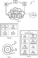
- Fig. 1 is a schematic diagram illustrating a communications network 10 where embodiments presented herein can be applied.
- the communications network 10 comprises network nodes 12a, 12b.
- the network nodes 12a, 12b may be radio access network (RAN) nodes.
- the network nodes may be radio base stations, base transceiver stations (BTSs), node Bs (NBs), and/or evolved node Bs (eNBs).
- BTSs base transceiver stations
- NBs node Bs
- eNBs evolved node Bs
- the network nodes 12a, 12b are operatively connected to entities of a core network 14.
- entities of a core network 14 include, but are not limited to, a Mobility Management Node (MMN) 13a, such as a Mobility Management Entity (MME), an Evolved Serving Mobile Location Center (E-SMLC) 13b, a Base station subsystem / Radio network subsystem (BSS/RNS) 13c, a Mobile Switching Center (MSC) 13d, and a Gateway Mobile Location Center (GMLC) 13e.
- MME Mobility Management Entity
- E-SMLC Evolved Serving Mobile Location Center
- BSS/RNS Base station subsystem / Radio network subsystem
- MSC Mobile Switching Center
- GMLC Gateway Mobile Location Center
- the functionalities of these entities are as such known in the art and further description thereof is therefore omitted.
- the core network 14 may comprise further entities performing their ordinary functionality as known in the art.
- the core network 14 is in turn operatively connected to a service and data providing Internet protocol
- a wireless device (WD) 11 may thus, by establishing a connection to one of the network nodes 12a, 12b access data and services of the IP network 15.
- wireless devices 11 include, but are not limited to, mobile stations, mobile phones, handsets, wireless local loop phones, user equipment (UE), smartphones, laptop computers, tablet computers, sensors, Internet-of-Things (IoT) devices, etc.
- One of the network nodes 12a acts as the serving, or source, network node (SNN) 12a of the wireless device 11, and the other of the network nodes 12b acts as the target network node (TNN) 12b of the wireless device 11.
- SNN serving, or source, network node
- TNN target network node
- the source network node 12a may be associated with a first, source, radio access technology (RAT)
- RAT radio access technology
- the target network node 12b may be associated with a second, target, RAT.
- the target RAT is different from the source RAT. Examples of RATs will be provided below.
- the wireless device 11 being operatively connected to a source/target network node has the same technical meaning as the wireless device 11 being operatively connected to a source/target RAT.
- the terms source/target network node and source/target RAT may be used interchangeably.
- the communications network 10 may comprise a plurality of network nodes 12a, 12b. Further, as the skilled person also understands, a plurality of wireless devices 11 may be operatively connected to each such network node 12a, 12b.
- emergency calls are an example of services which may require position determination of the wireless device 11.
- the LTE network should provide GNSS assistance information to the wireless device 11.
- the LTE network is already aware about the emergency situation because the wireless device 11 may attempt the emergency call by sending a non-access stratum (NAS) Extended Service Request with "service type” information element set to "emergency call”.
- NAS non-access stratum
- the core network of the LTE network is therefore notified about the request cause.
- the wireless device 11 may requests RRC Connection establishment to the LTE network with information element "establishment cause" set to "emergency”. Therefore the LTE network is notified about the request cause.
- the wireless device 11 may start its positioning determination whilst still operatively connected to an LTE-based source RAT and continue the positioning determination when operatively connected to a non-LTE-based target RAT. Further, the network should take the necessary actions to expect the positioning procedure to continue and be finalized in the target RAT. Also in case the wireless device 11 has an ongoing IMS emergency call with positioning procedure the positioning procedure should continue in the target RAT even if an SRVCC occurs.
- a wireless device 11 In order to obtain such position determination there is provided a wireless device 11, a method performed by the wireless device 11, a computer program comprising code, for example in the form of a computer program product, that when run on a processing unit of the wireless device 11, causes the processing unit to perform the method.
- a mobility management node 13a In order to obtain such position determination there is further provided a mobility management node 13a, a method performed by the mobility management node 13a, and a computer program comprising code, for example in the form of a computer program product, that when run on a processing unit of the mobility management node 13a, causes the processing unit to perform the method.
- FIG. 2a schematically illustrates, in terms of a number of functional units, the components of a wireless device 11 according to an embodiment.
- a processing unit 21 is provided using any combination of one or more of a suitable central processing unit (CPU), multiprocessor, microcontroller, digital signal processor (DSP), application specific integrated circuit (ASIC), field programmable gate arrays (FPGA) etc., capable of executing software instructions stored in a computer program product 41a (as in Fig. 4 ), e.g. in the form of a storage medium 23.
- the storage medium 23 may also comprise persistent storage, which, for example, can be any single one or combination of magnetic memory, optical memory, solid state memory or even remotely mounted memory.
- the wireless device 11 may further comprise a communications interface 22 for communications with a source network node 12a and a target network node 12b.
- the communications interface 22 may comprise one or more transmitters and receivers, comprising analogue and digital components and a suitable number of antennas for radio communications.
- the processing unit 21 controls the general operation of the wireless device 11 e.g. by sending data and control signals to the communications interface 22 and the storage medium 23, by receiving data and reports from the communications interface 22, and by retrieving data and instructions from the storage medium 23.
- Other components, as well as the related functionality, of the wireless device 11 are omitted in order not to obscure the concepts presented herein.
- Fig. 2b schematically illustrates, in terms of a number of functional modules, the components of a wireless device 11 according to an embodiment.
- the wireless device 11 of Fig. 2b comprises a number of functional modules; a detect module 21a configured to perform below step S102, a start procedure module 21b configured to perform below step S104, a keep values module 21c configured to perform below step S106, and a continue procedure module 21d configured to perform below step S108.
- each functional module 21a-h may be implemented in hardware or in software.
- one or more or all functional modules 21a-h may be implemented by the processing unit 21, possibly in cooperation with functional units 22 and/or 23.
- the processing unit 21 may thus be arranged to from the storage medium 23 fetch instructions as provided by a functional module 21a-h and to execute these instructions, thereby performing any steps as will be disclosed hereinafter.
- FIG. 3a schematically illustrates, in terms of a number of functional units, the components of a mobility management node 13a according to an embodiment.
- a processing unit 31 is provided using any combination of one or more of a suitable central processing unit (CPU), multiprocessor, microcontroller, digital signal processor (DSP), application specific integrated circuit (ASIC), field programmable gate arrays (FPGA) etc., capable of executing software instructions stored in a computer program product 41b (as in Fig. 4 ), e.g. in the form of a storage medium 33.
- CPU central processing unit
- DSP digital signal processor
- ASIC application specific integrated circuit
- FPGA field programmable gate arrays
- the storage medium 33 may also comprise persistent storage, which, for example, can be any single one or combination of magnetic memory, optical memory, solid state memory or even remotely mounted memory.
- the mobility management node 13a may further comprise a communications interface 32 for communications with functional entities and devices in the core network 14 as well as network nodes 12a, 12b of radio access networks.
- the communications interface 32 may comprise one or more transmitters and receivers, comprising analogue and digital components and a suitable number of interfaces for wireline communications.
- the processing unit 31 controls the general operation of the mobility management node 13a e.g. by sending data and control signals to the communications interface 32 and the storage medium 33, by receiving data and reports from the communications interface 32, and by retrieving data and instructions from the storage medium 33.
- Other components, as well as the related functionality, of the mobility management node 13a are omitted in order not to obscure the concepts presented herein.
- Fig. 3b schematically illustrates, in terms of a number of functional modules, the components of a mobility management node 13a according to an embodiment.
- the mobility management node 13a of Fig. 3b comprises a number of functional modules; a detect module 31a configured to perform below step S202, and a send and/or receive module 31b configured to perform below steps S04, S208, S210.
- the mobility management node 13a of Fig. 3b may further comprise a number of optional functional modules, such as a monitor module 31c configured to perform below step S06.
- the functionality of each functional module 31a-c will be further disclosed below in the context of which the functional modules 31a-c may be used. In general terms, each functional module 31a-c may be implemented in hardware or in software.
- one or more or all functional modules 31a-c may be implemented by the processing unit 31, possibly in cooperation with functional units 32 and/or 33.
- the processing unit 31 may thus be arranged to from the storage medium 33 fetch instructions as provided by a functional module 31a-c and to execute these instructions, thereby performing any steps as will be disclosed hereinafter.
- the mobility management node 13a may be provided as a standalone device or as a part of a further device.
- the mobility management node 13a may be, or be provided in, a Mobility Management Entity, MME.
- Fig. 4 shows one example of a computer program product 41a, 41b comprising computer readable means 43.
- a computer program 42a can be stored, which computer program 42a can cause the processing unit 21 and thereto operatively coupled entities and devices, such as the communications interface 22 and the storage medium 23, to execute methods according to embodiments described herein.
- the computer program 42a and/or computer program product 41a may thus provide means for performing any steps of the wireless device 11 as herein disclosed.
- a computer program 42b can be stored, which computer program 42b can cause the processing unit 31 and thereto operatively coupled entities and devices, such as the communications interface 32 and the storage medium 33, to execute methods according to embodiments described herein.
- the computer program 42b and/or computer program product 41b may thus provide means for performing any steps of the mobility management node 13a as herein disclosed.
- the computer program product 41a, 41b is illustrated as an optical disc, such as a CD (compact disc) or a DVD (digital versatile disc) or a Blu-Ray disc.
- the computer program product 41a, 41b could also be embodied as a memory, such as a random access memory (RAM), a read-only memory (ROM), an erasable programmable read-only memory (EPROM), or an electrically erasable programmable read-only memory (EEPROM) and more particularly as a non-volatile storage medium of a device in an external memory such as a USB (Universal Serial Bus) memory or a Flash memory, such as a compact Flash memory.
- RAM random access memory
- ROM read-only memory
- EPROM erasable programmable read-only memory
- EEPROM electrically erasable programmable read-only memory
- the computer program 42a, 42b is here schematically shown as a track on the depicted optical disk, the computer program 42a, 42b can be stored in any
- Figs. 5 and 6 are flow charts illustrating embodiments of methods for position determination of a wireless device 11 as performed by the wireless device 11.
- Figs. 7 and 8 are flow charts illustrating embodiments of methods for position determination of a wireless device 11 as performed by the mobility management node 13a.
- the methods are advantageously provided as computer programs 42a, 42b.
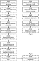
- Fig. 5 illustrating a method for position determination of a wireless device 11 as performed by the wireless device 11 according to an embodiment.
- the wireless device 11 is configured to, in a step S102, detect an indicator requiring a handover of the wireless device to a target RAT. Examples of such an indicator (and thus how it may be detected) will be provided below.
- the indicator is detected whilst the wireless device 11 is operatively connected to a source RAT. Examples of source RATs and target RATs will be provided below.
- the indicator further requires a position of the wireless device 11 to be determined.
- the wireless device 11 is configured to, in a step S104, start a positioning detection procedure of the wireless device 11.
- this procedure should start as early as possible. Particularly, this procedure is started before the wireless device 11 is handed over to the target RAT.
- the positioning detection procedure involves processing of positioning measurements. Examples of such positioning measurements and how they may be processed will be provided below.
- the wireless device 11 is configured to, in a step S106, keep the positioning measurements of the positioning detection procedure whilst the wireless device 11 is handed over from the source RAT to the target RAT.
- the wireless device 11 may then continue the positioning detection procedure using the kept positioning measurements.
- the wireless device 11 is configured to, in a step S108, continue the positioning detection procedure using the positioning measurements whilst being operatively connected to the target RAT.
- the source RAT network When the wireless device 11 participates in, e.g., a CSFB procedure, for example due to an emergency call, the source RAT network already triggers a positioning procedure and sends positioning assistance information to the wireless device 11 before the wireless device 11 performs the RAT change (i.e., from being operatively connected to a source network node 12a in the source RAT to being operatively connected to a target network node 12b in the target RAT).
- the wireless device 11 is thereby enabled to start performing its positioning determination procedure and continue this procedure whilst the RAT change procedure is still ongoing.
- the positioning determination procedure will continue during the RAT change and be finalized when the wireless device 11 is operatively connected to the target RAT.
- the indicator may be an emergency call indicator. Hence the wireless device 11 may detect the indicator during set-up of the emergency call.
- the wireless device 11 may not be capable of performing Internet protocol multimedia subsystem (IMS) emergency calls in the source RAT.
- IMS Internet protocol multimedia subsystem
- the handover involves a circuit switched fallback (CSFB) of the wireless device 11.
- the handover involves a single radio voice call continuity (SRVCC) procedure.
- CSFB circuit switched fallback
- SSVCC single radio voice call continuity
- the positioning detection procedure may involve the wireless device 11 to perform, or take part in, at least one sub-procedure.
- the positioning detection procedure involves a sub-procedure of performing a network initiated location request (NILR) positioning procedure whilst being operatively connected to the source RAT.
- NILR network initiated location request
- the positioning measurements may be global navigation satellite system (GNSS) measurements.
- the GNSS measurements may be assisted GNSS (A-GNSS) assistance data items.
- the A-GNSS assistance data items may be received from an evolved serving mobile location center (E-SMLC).
- E-SMLC evolved serving mobile location center
- the wireless device 11 may be configured to acquire such measurements and/or data items.
- the wireless device 11 has an ongoing IMS emergency call and an ongoing emergency positioning procedure
- the positioning procedure may continue sufficiently long for Assistance Data and GNSS measurements to be delivered to the wireless device 11.
- the source RAT may be a Long Term Evolution (LTE) compliant network.
- LTE Long Term Evolution
- the wireless device 11 may be operatively connected to a source network node 12a being an eNB.
- the target RAT may be a non-LTE compliant network, such as GSM or WCDMA.
- the wireless device 11 may be operatively connected to a target network node 12b not being an eNB (such as an NB or a BTS).
- Fig. 6 illustrating methods for position determination of a wireless device 11 as performed by the wireless device 11 according to further embodiments.
- the process may be complete by the wireless device 11 returning either the position (i.e., a wireless device-based approach) or the measurement results (i.e., a wireless device-assisted approach) once in the new RAT.
- the wireless device 11 is configured to, in an optional step S108a, continue the positioning detection procedure by completing the positioning detection procedure so as to determine a position of the wireless device 11; and, in an optional step S108b, provide the position to the target RAT.
- the wireless device 11 is configured to, in an optional step S108c, provide the positioning measurements to the target RAT.
- the wireless device 11 may respond to having detected the indicator in step S102.
- the wireless device 11 may be configured to in response to detecting the indicator, in an optional step S102a, send a non-access stratum (NAS) extended service request with a service type information element set to emergency call to the source RAT.
- NAS non-access stratum
- the wireless device 11 may be configured to in response to detecting the indicator, in an optional step S102b, request a radio resource control (RRC) connection establishment with information element establishment cause set to emergency to the source RAT.
- RRC radio resource control
- the wireless device 11 may be handed over. For example, being handed over from the source RAT to the target RAT may require the wireless device 11 to be configured to, in an optional step S106a, receive information elements for redirection of the wireless device 11 to the target RAT.
- the information elements for redirection may be received in a RRC connection release message.
- Fig. 7 illustrating a method for position determination of a wireless device 11 as performed by the mobility management node 13a according to an embodiment.
- the mobility management node 13a is configured to, in a step S202, detect an indication of a wireless device 11.
- the wireless device 11 is operatively connected to a source RAT.
- the indication requires a handover of the wireless device 11 to a target RAT.
- the mobility management node 13a is configured to, in response thereto, in a step S204 send a Location Services Application Protocol (LCS-AP) location request message to an evolved serving mobile location center (E-SMLC) 16 of the wireless device 11.
- LCS-AP Location Services Application Protocol
- E-SMLC evolved serving mobile location center
- the mobility management node 13a is configured to, in a step S208, send, upon fulfilment of a criterion relating to the indication of the wireless device 11, a LCS-AP location abort request message to the E-SMLC 13b.
- the indicator may be an emergency call indicator.
- Fig. 8 illustrating methods for position determination of a wireless device 11 as performed by the mobility management node 13a according to further embodiments.
- the mobility management node 13a may be configured to, in an optional step S206, monitor transmission of assisted GNSS (A-GNSS) assistance data items from the E-SMLC 13b to the wireless device 11. The criterion may then be fulfilled when a configured number of data items have been sent from the E-SMLC 13b to the wireless device 11.
- A-GNSS assisted GNSS
- the criterion relates to the time elapsed.
- the criterion may be fulfilled when a configured time interval starting at the detection of the indication has finished.
- the mobility management node 13a may be configured to, in a step S210, send an S1-AP context modification request.
- the S1-AP context modification request may comprise a circuit switched fallback indicator.
- the S1-AP context modification request may be sent to the source RAT upon the mobility management node 13a having sent the LCS-AP location abort request.
- the first particular embodiment relates to a CSFB scenario.
- step S301 The wireless device 11 makes an Extended Service Request for mobile originating CSFB indicating that the purpose is an emergency call.
- One way to implement step S301 is to perform steps S102, step S102a and, optionally, step S102b.
- the mobility management node 13a detects the request for emergency call CSFB and also confirms from capabilities of the wireless device 11 that the wireless device 11 supports LPP. Instead of immediately starting the CSFB procedure the mobility management node 13a first sends an LCS-AP Location Request message to the E-SMLC 13b.
- One way to implement step S302 is to perform step S202.
- step S303 The E-SMLC 13b delivers a preconfigured set of A-GNSS Assistance Data to the wireless device 11 and sends a LPP request Location Information requesting GNSS measurements.
- One way to implement step S303 is to perform any of step S104 and step S206.
- step S304 After a configured number of LCS-AP messages has been delivered to the wireless device 11 and/or after timeout, the mobility management node 13a sends an LCS-AP Location Abort Request to the E-SMLC 13b.
- One way to implement step S304 is to perform step S208.
- step S305 The mobility management node 13a sends an S1-AP Context Modification Request with a CSFB indicator to the source network node 12a.
- One way to implement step S305 is to perform step S210.
- step S306 The source network node 12a sends a Cell RRC Connection Release message to the wireless device 11. The wireless device 11 thus receives the Cell RRC Connection Release message.
- One way to implement step S306 is to perform any of step S106a and step S210.
- step S307 The wireless device 11 keeps received Assistance Data and, if feasible, continues its started processing of received GNSS measurements.
- One way to implement step S307 is to perform any of step S106.
- step S308 Fall back of the wireless device 11 is performed by the wireless device 11 being handed over to a target network node 12b in GERAN or UTRAN.
- One way to implement step S308 is to perform step S106a.
- the MSC 13d sends a Location Request message to the BSS/RNS 13c. This may be triggered by the request from the GMLC 13e or triggered internally in the MSC 13d due to an emergency call being set up by the wireless device 11.
- S311 The BSS/RNS 13c initiates a positioning procedure.
- S312 A Location Response is sent from the BSS/RNS 13c to the MSC 13d.
- S313 The MSC 13d sends a Location Response to the GMLC 13e.
- the second particular embodiment relates to an SR-VCC scenario.
- step S401 A positioning session of a wireless device 11 is ongoing where the E-SMLC 13b has started to exchange LPP messages with the wireless device 11.
- One way to implement step S401 is to perform any of step S102 and step S102a.
- step S402 The source network node 12a detects that handover to GERAN or UTRAN is required for the wireless device 11 and initiates an SR-VCC procedure with the mobility management node 13a.
- One way to implement step S402 is to perform any of step S102b and step S202.
- step S403 The mobility management node 13a identifies that a handover of the wireless device 11 will occur.
- the mobility management node 13a waits until a configured time after the start of the positioning session in step S401 has elapsed, or confirms that a configured number of LPP messages has been delivered to the wireless device 11 from the E-SMLC 13b.
- the mobility management node 13a then sends an LCS-AP Location Abort Request to the E-SMLC 13b.
- One way to implement step S403 is to perform any of step S206 and step S208.
- step S405 The wireless device 11 keeps received Assistance Data and, if feasible, continues the started processing of received GNSS measurements.
- One way to implement step S405 is to perform any of step S106, S106a, and step S108.
- step S406 The wireless device 11 is handed over to a target network node 12b in GERAN or UTRAN.
- One way to implement step S406 is to perform any of step S106a and step S210.
- the GMLC 13e may send a location Request message .
- the MSC 13d sends a Location Request message to the BSS/RNS 13c.
- a Location Response message is sent by the BSS/RNS 13c to the MSC 13d.
- the MSC 13d sends a Location Response to the GMLC 13e.
Applications Claiming Priority (1)
| Application Number | Priority Date | Filing Date | Title |
|---|---|---|---|
| PCT/EP2014/076502 WO2016086992A1 (en) | 2014-12-04 | 2014-12-04 | Position determination of a wireless device |
Publications (2)
| Publication Number | Publication Date |
|---|---|
| EP3228134A1 EP3228134A1 (en) | 2017-10-11 |
| EP3228134B1 true EP3228134B1 (en) | 2021-10-20 |
Family
ID=52023478
Family Applications (1)
| Application Number | Title | Priority Date | Filing Date |
|---|---|---|---|
| EP14811804.5A Active EP3228134B1 (en) | 2014-12-04 | 2014-12-04 | Position determination of a wireless device |
Country Status (5)
| Country | Link |
|---|---|
| US (2) | US20160366631A1 (pt) |
| EP (1) | EP3228134B1 (pt) |
| BR (1) | BR112017011876B1 (pt) |
| MY (1) | MY189924A (pt) |
| WO (1) | WO2016086992A1 (pt) |
Families Citing this family (3)
| Publication number | Priority date | Publication date | Assignee | Title |
|---|---|---|---|---|
| EP3257213A1 (en) * | 2015-02-13 | 2017-12-20 | Telefonaktiebolaget LM Ericsson (publ) | Methods, apparatuses and computer program products for reducing media gap when connecting independent bearer paths |
| CN111770433B (zh) * | 2019-04-02 | 2022-01-14 | 华为技术有限公司 | 一种终端定位方法及装置 |
| US11722943B2 (en) * | 2020-12-17 | 2023-08-08 | Qualcomm Incorporated | Methods and apparatus for positioning enhancements based on conditional reconfiguration and handover feature support |
Family Cites Families (21)
| Publication number | Priority date | Publication date | Assignee | Title |
|---|---|---|---|---|
| CN101646248B (zh) * | 2008-08-07 | 2011-11-02 | 华为技术有限公司 | 封闭用户组信息处理方法、接入控制方法及系统和设备 |
| US9693184B2 (en) * | 2008-08-18 | 2017-06-27 | Qualcomm Incorporated | Control plane location solution to support wireless access |
| US8831555B2 (en) * | 2009-04-03 | 2014-09-09 | Qualcomm Incorporated | Reestablishment procedure for an emergency call |
| CN102396249B (zh) * | 2009-04-17 | 2015-07-29 | 日本电气株式会社 | 移动通信系统、基站、网关装置、核心网络装置以及通信方法 |
| US8942660B2 (en) * | 2009-06-05 | 2015-01-27 | Qualcomm Incorporated | Method and apparatus for performing handover of an emergency call between wireless networks |
| JP5621002B2 (ja) * | 2009-12-29 | 2014-11-05 | テレフオンアクチーボラゲット エル エムエリクソン(パブル) | LTEにおける測位サービス、位置特定サービス及び位置に基づくサービスのためのQoS識別を可能にするシグナリング・サポート |
| ES2541714T3 (es) * | 2010-02-09 | 2015-07-23 | T-Mobile International Austria Gmbh | Método para indicar una disponibilidad de llamada de emergencia a un equipo móvil (ME), método para establecer una llamada de emergencia |
| RU2567377C2 (ru) * | 2010-08-16 | 2015-11-10 | Телефонактиеболагет Л М Эрикссон (Пабл) | Узлы и способы для улучшения позиционирования |
| US10034205B2 (en) * | 2010-10-01 | 2018-07-24 | Telefonaktiebolaget Lm Ericsson (Publ) | Positioning measurements and carrier switching in multi-carrier wireless communication networks |
| RU2587428C2 (ru) * | 2010-10-05 | 2016-06-20 | Телефонактиеболагет Л М Эрикссон (Пабл) | Способ для установления входящего вызова в ситуации возврата к коммутации каналов (csfb) |
| FI20115297A0 (fi) * | 2011-03-29 | 2011-03-29 | Nethawk Oyj | Tilaajapäätelaitteen ohjaukseen ottaminen |
| US8489093B2 (en) * | 2011-04-07 | 2013-07-16 | Novatel Wireless, Inc. | Systems and methods for facilitating efficient vertical handoffs in a wireless communication system |
| US8700055B2 (en) * | 2011-08-30 | 2014-04-15 | Qualcomm Incorporated | Maintaining location based service session continuity during inter-RAT mobility |
| US9148824B2 (en) * | 2011-12-21 | 2015-09-29 | Telefonaktiebolaget L M Ericsson (Publ) | Methods and apparatus for controlling circuit switched fall back of a mobile station from E-UTRAN to UTRAN/GERAN in a full-multi-operator core network |
| CN104221422A (zh) * | 2012-01-27 | 2014-12-17 | 三星电子株式会社 | 移动通信系统中用于有效地控制接入以用于系统负载调节的方法和装置 |
| US8885752B2 (en) * | 2012-07-27 | 2014-11-11 | Intel Corporation | Method and apparatus for feedback in 3D MIMO wireless systems |
| EP2890163B1 (en) * | 2012-09-21 | 2016-09-14 | Huawei Technologies Co., Ltd. | Method, device and system for locating user equipment |
| US10271256B2 (en) * | 2013-01-04 | 2019-04-23 | Samsung Electronics Co., Ltd. | Method and system for providing enhanced packet data services to a user equipment |
| US9344991B2 (en) * | 2013-03-08 | 2016-05-17 | Qualcomm Incorporated | Methods and systems for responding to handover events during positioning sessions |
| US9894575B2 (en) * | 2013-05-10 | 2018-02-13 | Telefonaktiebolaget Lm Ericsson (Publ) | Methods and arrangements for enabling continuation of ongoing positioning measurements at handover |
| CN104918324A (zh) * | 2014-03-13 | 2015-09-16 | 电信科学技术研究院 | 一种定位方法的选择、控制方法及装置 |
-
2014
- 2014-12-04 BR BR112017011876-9A patent/BR112017011876B1/pt active IP Right Grant
- 2014-12-04 WO PCT/EP2014/076502 patent/WO2016086992A1/en active Application Filing
- 2014-12-04 US US14/416,332 patent/US20160366631A1/en not_active Abandoned
- 2014-12-04 MY MYPI2017702005A patent/MY189924A/en unknown
- 2014-12-04 EP EP14811804.5A patent/EP3228134B1/en active Active
-
2019
- 2019-06-24 US US16/450,055 patent/US10667236B2/en active Active
Non-Patent Citations (1)
| Title |
|---|
| 3GPP: "3rd Generation Partnership Project; Technical Specification Group Services and System Aspects; Circuit Switched (CS) fallback in Evolved Packet System (EPS); Stage 2 (Release 11)", 3GPP DRAFT; 23272-B10_CRS_IMPLEMENTED, 3RD GENERATION PARTNERSHIP PROJECT (3GPP), MOBILE COMPETENCE CENTRE ; 650, ROUTE DES LUCIOLES ; F-06921 SOPHIA-ANTIPOLIS CEDEX ; FRANCE, 22 June 2012 (2012-06-22), XP050625394 * |
Also Published As
| Publication number | Publication date |
|---|---|
| US20190313360A1 (en) | 2019-10-10 |
| US20160366631A1 (en) | 2016-12-15 |
| US10667236B2 (en) | 2020-05-26 |
| WO2016086992A1 (en) | 2016-06-09 |
| EP3228134A1 (en) | 2017-10-11 |
| BR112017011876B1 (pt) | 2023-03-14 |
| MY189924A (en) | 2022-03-22 |
| BR112017011876A2 (pt) | 2018-02-27 |
Similar Documents
| Publication | Publication Date | Title |
|---|---|---|
| US9609504B2 (en) | Node and method for monitoring a visitor location register registration of a wireless device | |
| EP2995120B1 (en) | Method and arrangement for enabling continuation of ongoing positioning measurements at handover | |
| US9749905B2 (en) | Circuit switched fall back improvements | |
| US8676226B2 (en) | Method of handling location service and related communication device | |
| US8666415B2 (en) | Method for canceling call initiation in radio access technology change | |
| US20190174379A1 (en) | Enhanced indication of network support of srvcc and/or voice-over-ims for an user equipment in an eps network | |
| CN106465197B (zh) | 一种从第二网络返回至第一网络的方法、设备和介质 | |
| US10667236B2 (en) | Position determination of a wireless device | |
| EP2725833A1 (en) | Method and apparatus for sending user equipment location information | |
| US20150350964A1 (en) | Mobile communications devices and methods for inter-radio access technology performance enhancement | |
| EP2523523B1 (en) | Methods for requesting emergency bearer services for low priority devices, and apparatuses using the same | |
| WO2013012371A1 (en) | Circuit-switched fallback for a mobile radio | |
| US10271256B2 (en) | Method and system for providing enhanced packet data services to a user equipment | |
| WO2018053691A1 (en) | Method and apparatus for service restoration in a wireless communication system | |
| US10142856B2 (en) | Technique for triggering mobility management specific procedure to avoid registration state mismatch between user equipment and network | |
| US9357377B2 (en) | Method of managing E-UTRA function of user equipment and related wireless communication system | |
| EP4354969A1 (en) | Event-triggered early measurement report reporting | |
| US9629034B1 (en) | Dynamic setup of fallback communications during handover | |
| WO2024068251A1 (en) | Managing of satellite assistance information during handover procedure |
Legal Events
| Date | Code | Title | Description |
|---|---|---|---|
| STAA | Information on the status of an ep patent application or granted ep patent |
Free format text: STATUS: THE INTERNATIONAL PUBLICATION HAS BEEN MADE |
|
| PUAI | Public reference made under article 153(3) epc to a published international application that has entered the european phase |
Free format text: ORIGINAL CODE: 0009012 |
|
| STAA | Information on the status of an ep patent application or granted ep patent |
Free format text: STATUS: REQUEST FOR EXAMINATION WAS MADE |
|
| 17P | Request for examination filed |
Effective date: 20170621 |
|
| AK | Designated contracting states |
Kind code of ref document: A1 Designated state(s): AL AT BE BG CH CY CZ DE DK EE ES FI FR GB GR HR HU IE IS IT LI LT LU LV MC MK MT NL NO PL PT RO RS SE SI SK SM TR |
|
| AX | Request for extension of the european patent |
Extension state: BA ME |
|
| RIN1 | Information on inventor provided before grant (corrected) |
Inventor name: BUSIN, AKE Inventor name: CRISCI, GIUSEPPE |
|
| RIN1 | Information on inventor provided before grant (corrected) |
Inventor name: BUSIN, AKE Inventor name: CRISCI, GIUSEPPE |
|
| DAX | Request for extension of the european patent (deleted) | ||
| STAA | Information on the status of an ep patent application or granted ep patent |
Free format text: STATUS: EXAMINATION IS IN PROGRESS |
|
| 17Q | First examination report despatched |
Effective date: 20190613 |
|
| STAA | Information on the status of an ep patent application or granted ep patent |
Free format text: STATUS: EXAMINATION IS IN PROGRESS |
|
| RIC1 | Information provided on ipc code assigned before grant |
Ipc: H04W 36/00 20090101ALN20210422BHEP Ipc: H04W 64/00 20090101AFI20210422BHEP |
|
| RIC1 | Information provided on ipc code assigned before grant |
Ipc: H04W 36/00 20090101ALN20210423BHEP Ipc: H04W 64/00 20090101AFI20210423BHEP |
|
| GRAP | Despatch of communication of intention to grant a patent |
Free format text: ORIGINAL CODE: EPIDOSNIGR1 |
|
| STAA | Information on the status of an ep patent application or granted ep patent |
Free format text: STATUS: GRANT OF PATENT IS INTENDED |
|
| INTG | Intention to grant announced |
Effective date: 20210604 |
|
| GRAS | Grant fee paid |
Free format text: ORIGINAL CODE: EPIDOSNIGR3 |
|
| GRAA | (expected) grant |
Free format text: ORIGINAL CODE: 0009210 |
|
| STAA | Information on the status of an ep patent application or granted ep patent |
Free format text: STATUS: THE PATENT HAS BEEN GRANTED |
|
| AK | Designated contracting states |
Kind code of ref document: B1 Designated state(s): AL AT BE BG CH CY CZ DE DK EE ES FI FR GB GR HR HU IE IS IT LI LT LU LV MC MK MT NL NO PL PT RO RS SE SI SK SM TR |
|
| REG | Reference to a national code |
Ref country code: GB Ref legal event code: FG4D |
|
| REG | Reference to a national code |
Ref country code: CH Ref legal event code: EP |
|
| REG | Reference to a national code |
Ref country code: IE Ref legal event code: FG4D |
|
| REG | Reference to a national code |
Ref country code: DE Ref legal event code: R096 Ref document number: 602014080790 Country of ref document: DE |
|
| REG | Reference to a national code |
Ref country code: AT Ref legal event code: REF Ref document number: 1440955 Country of ref document: AT Kind code of ref document: T Effective date: 20211115 |
|
| REG | Reference to a national code |
Ref country code: LT Ref legal event code: MG9D |
|
| REG | Reference to a national code |
Ref country code: NL Ref legal event code: MP Effective date: 20211020 |
|
| REG | Reference to a national code |
Ref country code: AT Ref legal event code: MK05 Ref document number: 1440955 Country of ref document: AT Kind code of ref document: T Effective date: 20211020 |
|
| PG25 | Lapsed in a contracting state [announced via postgrant information from national office to epo] |
Ref country code: RS Free format text: LAPSE BECAUSE OF FAILURE TO SUBMIT A TRANSLATION OF THE DESCRIPTION OR TO PAY THE FEE WITHIN THE PRESCRIBED TIME-LIMIT Effective date: 20211020 Ref country code: LT Free format text: LAPSE BECAUSE OF FAILURE TO SUBMIT A TRANSLATION OF THE DESCRIPTION OR TO PAY THE FEE WITHIN THE PRESCRIBED TIME-LIMIT Effective date: 20211020 Ref country code: FI Free format text: LAPSE BECAUSE OF FAILURE TO SUBMIT A TRANSLATION OF THE DESCRIPTION OR TO PAY THE FEE WITHIN THE PRESCRIBED TIME-LIMIT Effective date: 20211020 Ref country code: BG Free format text: LAPSE BECAUSE OF FAILURE TO SUBMIT A TRANSLATION OF THE DESCRIPTION OR TO PAY THE FEE WITHIN THE PRESCRIBED TIME-LIMIT Effective date: 20220120 Ref country code: AT Free format text: LAPSE BECAUSE OF FAILURE TO SUBMIT A TRANSLATION OF THE DESCRIPTION OR TO PAY THE FEE WITHIN THE PRESCRIBED TIME-LIMIT Effective date: 20211020 |
|
| PG25 | Lapsed in a contracting state [announced via postgrant information from national office to epo] |
Ref country code: IS Free format text: LAPSE BECAUSE OF FAILURE TO SUBMIT A TRANSLATION OF THE DESCRIPTION OR TO PAY THE FEE WITHIN THE PRESCRIBED TIME-LIMIT Effective date: 20220220 Ref country code: SE Free format text: LAPSE BECAUSE OF FAILURE TO SUBMIT A TRANSLATION OF THE DESCRIPTION OR TO PAY THE FEE WITHIN THE PRESCRIBED TIME-LIMIT Effective date: 20211020 Ref country code: PT Free format text: LAPSE BECAUSE OF FAILURE TO SUBMIT A TRANSLATION OF THE DESCRIPTION OR TO PAY THE FEE WITHIN THE PRESCRIBED TIME-LIMIT Effective date: 20220221 Ref country code: PL Free format text: LAPSE BECAUSE OF FAILURE TO SUBMIT A TRANSLATION OF THE DESCRIPTION OR TO PAY THE FEE WITHIN THE PRESCRIBED TIME-LIMIT Effective date: 20211020 Ref country code: NO Free format text: LAPSE BECAUSE OF FAILURE TO SUBMIT A TRANSLATION OF THE DESCRIPTION OR TO PAY THE FEE WITHIN THE PRESCRIBED TIME-LIMIT Effective date: 20220120 Ref country code: NL Free format text: LAPSE BECAUSE OF FAILURE TO SUBMIT A TRANSLATION OF THE DESCRIPTION OR TO PAY THE FEE WITHIN THE PRESCRIBED TIME-LIMIT Effective date: 20211020 Ref country code: LV Free format text: LAPSE BECAUSE OF FAILURE TO SUBMIT A TRANSLATION OF THE DESCRIPTION OR TO PAY THE FEE WITHIN THE PRESCRIBED TIME-LIMIT Effective date: 20211020 Ref country code: HR Free format text: LAPSE BECAUSE OF FAILURE TO SUBMIT A TRANSLATION OF THE DESCRIPTION OR TO PAY THE FEE WITHIN THE PRESCRIBED TIME-LIMIT Effective date: 20211020 Ref country code: GR Free format text: LAPSE BECAUSE OF FAILURE TO SUBMIT A TRANSLATION OF THE DESCRIPTION OR TO PAY THE FEE WITHIN THE PRESCRIBED TIME-LIMIT Effective date: 20220121 Ref country code: ES Free format text: LAPSE BECAUSE OF FAILURE TO SUBMIT A TRANSLATION OF THE DESCRIPTION OR TO PAY THE FEE WITHIN THE PRESCRIBED TIME-LIMIT Effective date: 20211020 |
|
| REG | Reference to a national code |
Ref country code: DE Ref legal event code: R097 Ref document number: 602014080790 Country of ref document: DE |
|
| PG25 | Lapsed in a contracting state [announced via postgrant information from national office to epo] |
Ref country code: SM Free format text: LAPSE BECAUSE OF FAILURE TO SUBMIT A TRANSLATION OF THE DESCRIPTION OR TO PAY THE FEE WITHIN THE PRESCRIBED TIME-LIMIT Effective date: 20211020 Ref country code: SK Free format text: LAPSE BECAUSE OF FAILURE TO SUBMIT A TRANSLATION OF THE DESCRIPTION OR TO PAY THE FEE WITHIN THE PRESCRIBED TIME-LIMIT Effective date: 20211020 Ref country code: RO Free format text: LAPSE BECAUSE OF FAILURE TO SUBMIT A TRANSLATION OF THE DESCRIPTION OR TO PAY THE FEE WITHIN THE PRESCRIBED TIME-LIMIT Effective date: 20211020 Ref country code: MC Free format text: LAPSE BECAUSE OF FAILURE TO SUBMIT A TRANSLATION OF THE DESCRIPTION OR TO PAY THE FEE WITHIN THE PRESCRIBED TIME-LIMIT Effective date: 20211020 Ref country code: EE Free format text: LAPSE BECAUSE OF FAILURE TO SUBMIT A TRANSLATION OF THE DESCRIPTION OR TO PAY THE FEE WITHIN THE PRESCRIBED TIME-LIMIT Effective date: 20211020 Ref country code: DK Free format text: LAPSE BECAUSE OF FAILURE TO SUBMIT A TRANSLATION OF THE DESCRIPTION OR TO PAY THE FEE WITHIN THE PRESCRIBED TIME-LIMIT Effective date: 20211020 Ref country code: CZ Free format text: LAPSE BECAUSE OF FAILURE TO SUBMIT A TRANSLATION OF THE DESCRIPTION OR TO PAY THE FEE WITHIN THE PRESCRIBED TIME-LIMIT Effective date: 20211020 |
|
| REG | Reference to a national code |
Ref country code: CH Ref legal event code: PL |
|
| PLBE | No opposition filed within time limit |
Free format text: ORIGINAL CODE: 0009261 |
|
| STAA | Information on the status of an ep patent application or granted ep patent |
Free format text: STATUS: NO OPPOSITION FILED WITHIN TIME LIMIT |
|
| REG | Reference to a national code |
Ref country code: BE Ref legal event code: MM Effective date: 20211231 |
|
| 26N | No opposition filed |
Effective date: 20220721 |
|
| PG25 | Lapsed in a contracting state [announced via postgrant information from national office to epo] |
Ref country code: LU Free format text: LAPSE BECAUSE OF NON-PAYMENT OF DUE FEES Effective date: 20211204 Ref country code: IE Free format text: LAPSE BECAUSE OF NON-PAYMENT OF DUE FEES Effective date: 20211204 Ref country code: AL Free format text: LAPSE BECAUSE OF FAILURE TO SUBMIT A TRANSLATION OF THE DESCRIPTION OR TO PAY THE FEE WITHIN THE PRESCRIBED TIME-LIMIT Effective date: 20211020 |
|
| PG25 | Lapsed in a contracting state [announced via postgrant information from national office to epo] |
Ref country code: SI Free format text: LAPSE BECAUSE OF FAILURE TO SUBMIT A TRANSLATION OF THE DESCRIPTION OR TO PAY THE FEE WITHIN THE PRESCRIBED TIME-LIMIT Effective date: 20211020 Ref country code: FR Free format text: LAPSE BECAUSE OF NON-PAYMENT OF DUE FEES Effective date: 20211220 Ref country code: BE Free format text: LAPSE BECAUSE OF NON-PAYMENT OF DUE FEES Effective date: 20211231 |
|
| PG25 | Lapsed in a contracting state [announced via postgrant information from national office to epo] |
Ref country code: LI Free format text: LAPSE BECAUSE OF NON-PAYMENT OF DUE FEES Effective date: 20211231 Ref country code: CH Free format text: LAPSE BECAUSE OF NON-PAYMENT OF DUE FEES Effective date: 20211231 |
|
| PG25 | Lapsed in a contracting state [announced via postgrant information from national office to epo] |
Ref country code: IT Free format text: LAPSE BECAUSE OF FAILURE TO SUBMIT A TRANSLATION OF THE DESCRIPTION OR TO PAY THE FEE WITHIN THE PRESCRIBED TIME-LIMIT Effective date: 20211020 Ref country code: HU Free format text: LAPSE BECAUSE OF FAILURE TO SUBMIT A TRANSLATION OF THE DESCRIPTION OR TO PAY THE FEE WITHIN THE PRESCRIBED TIME-LIMIT; INVALID AB INITIO Effective date: 20141204 |
|
| PGFP | Annual fee paid to national office [announced via postgrant information from national office to epo] |
Ref country code: DE Payment date: 20221228 Year of fee payment: 9 |
|
| PG25 | Lapsed in a contracting state [announced via postgrant information from national office to epo] |
Ref country code: CY Free format text: LAPSE BECAUSE OF FAILURE TO SUBMIT A TRANSLATION OF THE DESCRIPTION OR TO PAY THE FEE WITHIN THE PRESCRIBED TIME-LIMIT Effective date: 20211020 |
|
| PGFP | Annual fee paid to national office [announced via postgrant information from national office to epo] |
Ref country code: GB Payment date: 20231227 Year of fee payment: 10 |