EP3227608B1 - Katalytische brenneranordnung - Google Patents
Katalytische brenneranordnung Download PDFInfo
- Publication number
- EP3227608B1 EP3227608B1 EP15837150.0A EP15837150A EP3227608B1 EP 3227608 B1 EP3227608 B1 EP 3227608B1 EP 15837150 A EP15837150 A EP 15837150A EP 3227608 B1 EP3227608 B1 EP 3227608B1
- Authority
- EP
- European Patent Office
- Prior art keywords
- fuel
- oxidant
- inlet
- catalytic burner
- mixing
- Prior art date
- Legal status (The legal status is an assumption and is not a legal conclusion. Google has not performed a legal analysis and makes no representation as to the accuracy of the status listed.)
- Not-in-force
Links
Images


Classifications
-
- C—CHEMISTRY; METALLURGY
- C01—INORGANIC CHEMISTRY
- C01B—NON-METALLIC ELEMENTS; COMPOUNDS THEREOF; METALLOIDS OR COMPOUNDS THEREOF NOT COVERED BY SUBCLASS C01C
- C01B3/00—Hydrogen; Gaseous mixtures containing hydrogen; Separation of hydrogen from mixtures containing it; Purification of hydrogen; Reversible storage of hydrogen
- C01B3/02—Production of hydrogen; Production of gaseous mixtures containing hydrogen
- C01B3/32—Production of hydrogen; Production of gaseous mixtures containing hydrogen by reaction of gaseous or liquid organic compounds with gasifying agents, e.g. water, carbon dioxide or air
- C01B3/34—Production of hydrogen; Production of gaseous mixtures containing hydrogen by reaction of gaseous or liquid organic compounds with gasifying agents, e.g. water, carbon dioxide or air by reaction of hydrocarbons with gasifying agents
-
- F—MECHANICAL ENGINEERING; LIGHTING; HEATING; WEAPONS; BLASTING
- F23—COMBUSTION APPARATUS; COMBUSTION PROCESSES
- F23C—METHODS OR APPARATUS FOR COMBUSTION USING FLUID FUEL OR SOLID FUEL SUSPENDED IN A CARRIER GAS OR AIR
- F23C13/00—Apparatus in which combustion takes place in the presence of catalytic material
-
- F—MECHANICAL ENGINEERING; LIGHTING; HEATING; WEAPONS; BLASTING
- F23—COMBUSTION APPARATUS; COMBUSTION PROCESSES
- F23D—BURNERS
- F23D14/00—Burners for combustion of a gas, e.g. of a gas stored under pressure as a liquid
- F23D14/02—Premix gas burners, i.e. in which gaseous fuel is mixed with combustion air upstream of the combustion zone
-
- F—MECHANICAL ENGINEERING; LIGHTING; HEATING; WEAPONS; BLASTING
- F23—COMBUSTION APPARATUS; COMBUSTION PROCESSES
- F23D—BURNERS
- F23D14/00—Burners for combustion of a gas, e.g. of a gas stored under pressure as a liquid
- F23D14/46—Details
- F23D14/62—Mixing devices; Mixing tubes
-
- H—ELECTRICITY
- H01—ELECTRIC ELEMENTS
- H01M—PROCESSES OR MEANS, e.g. BATTERIES, FOR THE DIRECT CONVERSION OF CHEMICAL ENERGY INTO ELECTRICAL ENERGY
- H01M8/00—Fuel cells; Manufacture thereof
- H01M8/06—Combination of fuel cells with means for production of reactants or for treatment of residues
- H01M8/0606—Combination of fuel cells with means for production of reactants or for treatment of residues with means for production of gaseous reactants
- H01M8/0612—Combination of fuel cells with means for production of reactants or for treatment of residues with means for production of gaseous reactants from carbon-containing material
-
- H—ELECTRICITY
- H01—ELECTRIC ELEMENTS
- H01M—PROCESSES OR MEANS, e.g. BATTERIES, FOR THE DIRECT CONVERSION OF CHEMICAL ENERGY INTO ELECTRICAL ENERGY
- H01M8/00—Fuel cells; Manufacture thereof
- H01M8/06—Combination of fuel cells with means for production of reactants or for treatment of residues
- H01M8/0606—Combination of fuel cells with means for production of reactants or for treatment of residues with means for production of gaseous reactants
- H01M8/0612—Combination of fuel cells with means for production of reactants or for treatment of residues with means for production of gaseous reactants from carbon-containing material
- H01M8/0618—Reforming processes, e.g. autothermal, partial oxidation or steam reforming
-
- H—ELECTRICITY
- H01—ELECTRIC ELEMENTS
- H01M—PROCESSES OR MEANS, e.g. BATTERIES, FOR THE DIRECT CONVERSION OF CHEMICAL ENERGY INTO ELECTRICAL ENERGY
- H01M8/00—Fuel cells; Manufacture thereof
- H01M8/06—Combination of fuel cells with means for production of reactants or for treatment of residues
- H01M8/0662—Treatment of gaseous reactants or gaseous residues, e.g. cleaning
-
- C—CHEMISTRY; METALLURGY
- C01—INORGANIC CHEMISTRY
- C01B—NON-METALLIC ELEMENTS; COMPOUNDS THEREOF; METALLOIDS OR COMPOUNDS THEREOF NOT COVERED BY SUBCLASS C01C
- C01B2203/00—Integrated processes for the production of hydrogen or synthesis gas
- C01B2203/02—Processes for making hydrogen or synthesis gas
- C01B2203/0205—Processes for making hydrogen or synthesis gas containing a reforming step
-
- C—CHEMISTRY; METALLURGY
- C01—INORGANIC CHEMISTRY
- C01B—NON-METALLIC ELEMENTS; COMPOUNDS THEREOF; METALLOIDS OR COMPOUNDS THEREOF NOT COVERED BY SUBCLASS C01C
- C01B2203/00—Integrated processes for the production of hydrogen or synthesis gas
- C01B2203/02—Processes for making hydrogen or synthesis gas
- C01B2203/0205—Processes for making hydrogen or synthesis gas containing a reforming step
- C01B2203/0227—Processes for making hydrogen or synthesis gas containing a reforming step containing a catalytic reforming step
- C01B2203/0233—Processes for making hydrogen or synthesis gas containing a reforming step containing a catalytic reforming step the reforming step being a steam reforming step
-
- C—CHEMISTRY; METALLURGY
- C01—INORGANIC CHEMISTRY
- C01B—NON-METALLIC ELEMENTS; COMPOUNDS THEREOF; METALLOIDS OR COMPOUNDS THEREOF NOT COVERED BY SUBCLASS C01C
- C01B2203/00—Integrated processes for the production of hydrogen or synthesis gas
- C01B2203/06—Integration with other chemical processes
-
- C—CHEMISTRY; METALLURGY
- C01—INORGANIC CHEMISTRY
- C01B—NON-METALLIC ELEMENTS; COMPOUNDS THEREOF; METALLOIDS OR COMPOUNDS THEREOF NOT COVERED BY SUBCLASS C01C
- C01B2203/00—Integrated processes for the production of hydrogen or synthesis gas
- C01B2203/06—Integration with other chemical processes
- C01B2203/066—Integration with other chemical processes with fuel cells
-
- C—CHEMISTRY; METALLURGY
- C01—INORGANIC CHEMISTRY
- C01B—NON-METALLIC ELEMENTS; COMPOUNDS THEREOF; METALLOIDS OR COMPOUNDS THEREOF NOT COVERED BY SUBCLASS C01C
- C01B2203/00—Integrated processes for the production of hydrogen or synthesis gas
- C01B2203/08—Methods of heating or cooling
- C01B2203/0805—Methods of heating the process for making hydrogen or synthesis gas
- C01B2203/0811—Methods of heating the process for making hydrogen or synthesis gas by combustion of fuel
- C01B2203/0822—Methods of heating the process for making hydrogen or synthesis gas by combustion of fuel the fuel containing hydrogen
-
- C—CHEMISTRY; METALLURGY
- C01—INORGANIC CHEMISTRY
- C01B—NON-METALLIC ELEMENTS; COMPOUNDS THEREOF; METALLOIDS OR COMPOUNDS THEREOF NOT COVERED BY SUBCLASS C01C
- C01B2203/00—Integrated processes for the production of hydrogen or synthesis gas
- C01B2203/12—Feeding the process for making hydrogen or synthesis gas
- C01B2203/1205—Composition of the feed
- C01B2203/1211—Organic compounds or organic mixtures used in the process for making hydrogen or synthesis gas
- C01B2203/1235—Hydrocarbons
-
- C—CHEMISTRY; METALLURGY
- C01—INORGANIC CHEMISTRY
- C01B—NON-METALLIC ELEMENTS; COMPOUNDS THEREOF; METALLOIDS OR COMPOUNDS THEREOF NOT COVERED BY SUBCLASS C01C
- C01B2203/00—Integrated processes for the production of hydrogen or synthesis gas
- C01B2203/12—Feeding the process for making hydrogen or synthesis gas
- C01B2203/1288—Evaporation of one or more of the different feed components
-
- F—MECHANICAL ENGINEERING; LIGHTING; HEATING; WEAPONS; BLASTING
- F23—COMBUSTION APPARATUS; COMBUSTION PROCESSES
- F23C—METHODS OR APPARATUS FOR COMBUSTION USING FLUID FUEL OR SOLID FUEL SUSPENDED IN A CARRIER GAS OR AIR
- F23C2900/00—Special features of, or arrangements for combustion apparatus using fluid fuels or solid fuels suspended in air; Combustion processes therefor
- F23C2900/03002—Combustion apparatus adapted for incorporating a fuel reforming device
-
- F—MECHANICAL ENGINEERING; LIGHTING; HEATING; WEAPONS; BLASTING
- F23—COMBUSTION APPARATUS; COMBUSTION PROCESSES
- F23C—METHODS OR APPARATUS FOR COMBUSTION USING FLUID FUEL OR SOLID FUEL SUSPENDED IN A CARRIER GAS OR AIR
- F23C2900/00—Special features of, or arrangements for combustion apparatus using fluid fuels or solid fuels suspended in air; Combustion processes therefor
- F23C2900/13001—Details of catalytic combustors
-
- F—MECHANICAL ENGINEERING; LIGHTING; HEATING; WEAPONS; BLASTING
- F23—COMBUSTION APPARATUS; COMBUSTION PROCESSES
- F23D—BURNERS
- F23D2203/00—Gaseous fuel burners
- F23D2203/007—Mixing tubes, air supply regulation
-
- F—MECHANICAL ENGINEERING; LIGHTING; HEATING; WEAPONS; BLASTING
- F23—COMBUSTION APPARATUS; COMBUSTION PROCESSES
- F23D—BURNERS
- F23D2900/00—Special features of, or arrangements for burners using fluid fuels or solid fuels suspended in a carrier gas
- F23D2900/31019—Mixing tubes combined with burner heads
-
- Y—GENERAL TAGGING OF NEW TECHNOLOGICAL DEVELOPMENTS; GENERAL TAGGING OF CROSS-SECTIONAL TECHNOLOGIES SPANNING OVER SEVERAL SECTIONS OF THE IPC; TECHNICAL SUBJECTS COVERED BY FORMER USPC CROSS-REFERENCE ART COLLECTIONS [XRACs] AND DIGESTS
- Y02—TECHNOLOGIES OR APPLICATIONS FOR MITIGATION OR ADAPTATION AGAINST CLIMATE CHANGE
- Y02E—REDUCTION OF GREENHOUSE GAS [GHG] EMISSIONS, RELATED TO ENERGY GENERATION, TRANSMISSION OR DISTRIBUTION
- Y02E60/00—Enabling technologies; Technologies with a potential or indirect contribution to GHG emissions mitigation
- Y02E60/30—Hydrogen technology
- Y02E60/50—Fuel cells
Definitions
- the present invention relates to a catalytic burner arrangement as defined in the claims, as well as to an auxiliary power assembly based on fuel technology comprising such a catalytic burner arrangement, according to claim 8.
- auxiliary power units energy is provided by a fuel cell stack.
- hydrogen is usually used for the operation of the fuel cell.
- hydrogen is usually produced by so called fuel reformers which generate a hydrogen rich gas from hydrocarbon fuels, like diesel, by means of a catalyst.
- fuel reformers which generate a hydrogen rich gas from hydrocarbon fuels, like diesel, by means of a catalyst.
- steam is additionally used for the fuel reforming reaction.
- the heat required for the production of steam may be provided by use of a catalytic burner arranged downstream of the fuel cell or fuel cell stack, wherein air and excess hydrogen exiting the fuel cell stack are combusted over a catalyst to release energy, which can be used for the steam production.
- the known catalytic burners have a housing defining a reaction chamber with an inlet for fuel (hydrogen) and an inlet for oxidant (air), whereby fuel and oxidant are introduced into the reaction chamber.
- the housing further incorporates a catalyst, which is arranged downstream of the inlets, where hydrogen and air catalytically react with each other.
- the problem of the known catalytic burners is that air and hydrogen often react uncontrolled upstream of the catalyst as soon as being brought in contact with each other. In some cases air may even enter the fuel inlet, whereby such an uncontrolled combustion may also take place in the pipes. However, these uncontrolled combustions may damage the pipes as well as the burner itself. Additionally, often the mixing of air and fuel is inhomogeneous, which in turn results in the development of hotspots in the catalyst, which might damage the catalyst and produce unwanted emissions.
- the object of the present invention is therefore to provide a catalytic burner, which hinders ignition of the hydrogen in the pipes and provides a homogenous mixture of air and fuel.
- a catalytic burner arrangement which comprises at least a catalytic burner unit and a mixing unit.
- the catalytic burner unit comprises a housing which defines a reaction chamber in which a catalyst is arranged.
- the catalyst is adapted to react a fuel, particularly a hydrogen containing fluid with an oxidant, particularly air, for producing heat.
- the housing further has a fluid inlet for supplying a fluid stream into the housing and a fluid outlet for exiting a fluid stream from the housing.
- the mixing unit in turn forms a mixing chamber in which fuel and oxidant are mixed and comprises a fuel inlet and an oxidant inlet as well as a fuel-oxidant-mixture outlet.
- the fuel inlet of the catalytic burner unit merges with the fuel-oxidant-outlet of the mixing unit so that the fuel-oxidant-mixture from the mixing chamber may be transported to the reaction chamber of the catalytic burner unit.
- said fuel-oxidant-outlet of the mixing chamber is pipe-shaped and extents into the mixing chamber of the mixing unit.
- fuel and oxidant are guided in a swirl around the fuel-oxidant-outlet and are forced to stream upwards and to change stream direction before the fuel/oxidant mixture may enter the fuel-oxidant-outlet.
- pipe-shaped in the context of the present invention refers to an elongated hollow element, which may have a cylindrical or prismatic form.
- Said hollow element has at least two openings. At least one first opening allows an entrance of the fuel-oxidant mixture into the hollow element and at least one second opening allows an exit of the fuel-oxidant mixture from the hollow element and thereby from the mixing unit. Thereby, the at least one first opening is arranged inside the mixing chamber. It should be further explicitly noted that more than one opening as first opening and more than one opening as second opening may be provided.
- said fuel inlet of the mixing chamber is arranged upstream of said oxidant inlet.
- This staggered arrangement of the inlets prevents the oxidant from entering the fuel inlet and thereby prevents an uncontrolled ignition of the fuel.
- the staggered arrangement alone also provides an improved mixing and prevents uncontrolled combustion.
- a length of the pipe-shaped fuel-oxidant-outlet extents over the oxidant inlet and/or the fuel inlet. Thereby, it may be preferred if the fuel-oxidant-outlet extends over both the oxidant inlet and the fuel inlet. In both embodiments, the swirl and the stream redirection may be maximized.
- the fuel inlet of the mixing chamber is arranged upstream of said oxidant inlet.
- the oxidant is reliably hindered from entering the fuel inlet and reacting uncontrolled.
- the fuel inlet and oxidant inlet are arranged angled to a direction of a main fluid stream streaming through the fuel-oxidant-mixture outlet to the reaction chamber of the catalytic burner.
- the angled arrangement provides a homogenous mixture as the fluid needs to be redirected from the entrance direction to its exit direction, whereby a mixing of the fluids is performed.
- the fuel inlet and/or the oxidant inlet are designed as at least one pipe having a longitudinal axis, whereby the directed fluid streams are provided.
- said mixing unit is prismaticly or cylindrically shaped having two basis plates and at least three side surfaces or a mantel side, wherein the fuel inlet and the oxidant inlet are arranged in the side surfaces or in the mantel side, and the fuel-oxidant-mixture outlet is arranged at one of the basis plates.
- At least one of the directed fluid streams are offset from a longitudinal axis of the mixing chamber, whereby at least one tangential fluid stream is provided.
- tangential fluid streams By means of the tangential fluid streams a homogenous mixture may be achieved.
- the longitudinal axis of the fuel inlet and/or of the oxidant inlet are inclined to a cross sectional plane of the mixing chamber.
- the oxidant inlet and the fuel inlet are arranged substantially rectangular to each other, whereby both the mixing is improved and an unwanted ignition is reliably avoided.
- a further aspect of the present application relates to an auxiliary power assembly based on fuel cell technology which comprises at least a fuel processing assembly which is adapted to convert hydrocarbon fuels into a hydrogen rich gas for fuel cells by using at least hydrocarbon fuel and steam.
- a fuel processing assembly which is adapted to convert hydrocarbon fuels into a hydrogen rich gas for fuel cells by using at least hydrocarbon fuel and steam.
- Downstream of the processor assembly at least one fuel cell or fuel cell stack for providing auxiliary power is arranged.
- a catalytic burner unit is provided which is adapted to burn unused hydrogen exiting from the fuel cell or the fuel cell stack by using an oxidant, such as air or oxygen, and a catalyst for reacting said oxidant and hydrogen to heat, wherein said heat in turn is used for the production of steam used in the fuel processing assembly.
- the catalytic burner is designed as described above.
- Fig. 1 shows a schematic illustration of an auxiliary power unit, APU, system 100 based on fuel technology for providing electric power.
- the APU system 100 comprises a fuel reformer 102 which is adapted to produce a hydrogen rich gas 104 from a hydrocarbon fuel 105.
- the hydrogen rich gas 104 is introduced into a fuel cell stack 106 arranged downstream of the fuel reformer 102.
- electric energy 107 is produced by guiding hydrogen to an anode side of a proton electron membrane and an oxidant to a cathode side.
- Excess hydrogen 108, which is not used in the fuel cell stack may then be transferred to a catalytic burner assembly 110, where the excess hydrogen 108 is reacted with air to produce heat 112.
- the heat 112 is then used for producing steam 114 which in turn is used in the fuel reformer 102 for the conversion of hydrocarbon fuel 105 to hydrogen rich gas 108.
- Fig. 2 shows a schematic illustration of two alternative embodiments of the catalytic burner assembly 110.
- the burner assembly 110 comprises at least two units, namely a burner unit 10 and a mixing unit 20.
- the burner unit 10 comprises a housing 12 defining a reaction chamber 13 in which a catalyst 14 is incorporated. Further the housing 12 comprises a fluid inlet 16 and a fluid outlet 18.
- the mixing unit 20 is arranged in close vicinity to the burning unit 10 and adapted to provide a homogenous mixture of air and hydrogen, which is fed through the fluid inlet 16 into the housing 12 and to the catalyst 14.
- the mixing unit 20 itself comprises a fuel inlet 22 and an oxidant inlet 24, wherein fuel and oxidant are mixed in a mixing chamber 26 and may exit the mixing unit 20 through a fuel-oxidant mixture outlet 28.
- Fig. 2 and 4 further depict that the fuel inlet 22 and the oxidant inlet 24 are angled to a fluid flow direction 30 from the mixing unit 20 to the burner unit 10.
- the mixing unit 20 may be cylindrically shaped having a mantel side 32 and two base plates 34 and 36.
- the cylindrically shape also any other prismatic shape is possible, wherein two base plates 34 and 36 are connected by at least three side surfaces 32.
- the fuel-oxidant-outlet 28 is a pipe-shaped hollow element and its length L extends at least over one of the inlets 22; 24 in the mixing chamber 26.
- the pipe-shaped fuel-oxidant outlet 28 By extending the pipe-shaped fuel-oxidant outlet 28 over at least one of the inlets 22; 24, the risk of oxidant entering the fuel inlet, which may cause uncontrolled combustions, is significantly reduced. Additionally, the fuel inlet may be arranged upstream of the oxidant inlet 24, whereby the risk of uncontrolled combustions is further reduced.
- the pipe-shaped fuel-oxidant outlet 28 further comprises a first opening 28-1 arranged in the mixing chamber 26 and a second opening 28-2 which is provided in a bottom plate 34 of the mixing unit 20. Thereby it should be noted that more than one opening may be provided as first and/or second opening 28-1, 28-2.
- the fuel inlet 22 is arranged upstream of the oxidant inlet 24, whereby an entering of the oxidant into the fuel inlet 22 is avoided. Thereby an unwanted ignition of oxidant and fuel inside the fuel inlet 22 is avoided.
- the fuel-oxidant mixture outlet 28 merges with the fluid inlet 16 of the burner unit 10.
- the pipe-shaped fuel-oxidant outlet 28 is elongated, or that a connection pipe is arranged between the burner unit 10 and the mixing unit 20, which fluidly connects the fuel-oxidant-mixture outlet 28 and the fluid inlet 16.
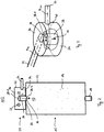
- Fig. 3 shows a detailed spatial view of the mixing unit 20 as shown in Fig. 2 .
- the fuel inlet 22 and the oxidant inlet 24 are arranged at the mantel side 32, wherein the fuel oxidant mixture outlet 28 is arranged at/in the bottom base plate 34.
- the fuel inlet 22 and the oxidant inlet 24 are pipe-shaped providing longitudinal axes A 22 , A 24 , whereby a directed fuel stream 38 respectively oxidant stream 40 are provided.
- These directed streams 38 and 40 are deviated by the walls 32 of the mixing unit 20 into a circular motion 41, whereby turbulences are introduced in the reaction chamber 26. Thereby a mixing of fuel and oxidant is performed.
- the mixed gas stream has to undergo a stream redirection from the circular motion the linear motion through the outlet 28, whereby further perturbations may be caused in the fluid streams and the homogeneity of the mixing may even be further improved.
- the pipe-shaped fuel-oxidant outlet 28 intensifies the induced swirling motion and the redirection of the fluid streams, whereby the mixing is enhanced.
- the fuel inlet 22 and the oxidant inlet 24 may be on the same level. Even if an arrangement at the same level is in principle also possible without a pipe-shaped fuel-oxidant-outlet 28, the risk of oxidant entering the fuel pipe 22 increases. In this case, it is therefore preferred to arrange the fuel inlet 22 upstream of the oxidant inlet 24 in order to hinder the oxidant from entering the fuel inlet 22.
- the fuel inlet 22 and the oxidant inlet 24 are arranged in such a way that the respective fluid streams enter the mixing chamber tangentially as depicted in the top view of Fig. 4 .
- the swirling motion in the chamber 26 and thereby the homogeneity of the mixing may be maximized.
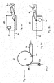
- Fig. 5a and 5b show a further optional detail of the mixing device 20.
- the axes A 22 , A 24 of the fuel inlet pipe 22 respectively the oxidant inlet pipe 24 may be inclined by a predetermined angle ⁇ ; ⁇ in relation to a cross sectional plane 42 of the mixing unit 20.
- these angles ⁇ ; ⁇ is relatively small, preferably below 10° for ensuring that the fluid streams have a sufficiently long stay time in the mixing chamber 26 for developing the desired homogenous mixture.
- the inclination further ensures that air streaming through the oxidant 24 does not enter the fuel pipe 22.
- the angles ⁇ ; ⁇ may provide the same or a different inclination.
- the inventive mixing unit hinders ignition of hydrogen in the pipes. Additionally, the mixing unit also reduces emissions of unwanted byproducts produced during the catalytic burning process since all combustible gases are burned due to the homogenous mixing. Additionally, only little excess air is necessary for reaching complete combustion, and increasing the temperature to the desired temperature suitable for methane combustion performed in the catalyst, which in turn reduces the amount of unwanted byproducts. Consequently, the catalytic burner efficiency may be maximized as the reactor temperature and hence the methane conversion is quickly in the desired range.
Landscapes
- Engineering & Computer Science (AREA)
- Chemical & Material Sciences (AREA)
- Chemical Kinetics & Catalysis (AREA)
- Combustion & Propulsion (AREA)
- General Engineering & Computer Science (AREA)
- Mechanical Engineering (AREA)
- Life Sciences & Earth Sciences (AREA)
- Manufacturing & Machinery (AREA)
- Sustainable Development (AREA)
- Sustainable Energy (AREA)
- Electrochemistry (AREA)
- General Chemical & Material Sciences (AREA)
- Organic Chemistry (AREA)
- Inorganic Chemistry (AREA)
- General Health & Medical Sciences (AREA)
- Health & Medical Sciences (AREA)
- Hydrogen, Water And Hydrids (AREA)
- Fuel Cell (AREA)
- Gas Burners (AREA)
Claims (8)
- Katalytische Brenneranordnung (110) mit zumindest
einer katalytischen Brennereinheit (10) mit einem Gehäuse (12), das eine Reaktionskammer (13) aufweist, in welcher ein Katalysator (14) angeordnet ist, wobei der Katalysator (14) dazu ausgelegt ist, Brennstoff, insbesondere ein wasserstoffhaltiges Fluid, mit einem Oxidiermittel, insbesondere Luft, zu reagieren, um Wärme zu erzeugen, wobei das Gehäuse (12) ein Fluideinlass (14) aufweist, um einen Fluidstrom in das Gehäuse (12) einzuführen, und einen Fluidauslass (18) aufweist, um einen Fluidstrom aus dem Gehäuse (12) auszulassen,
und wobei die katalytische Brennereinheit (110) weiterhin eine Mischeinheit (20) aufweist, die eine Mischkammer (26) bildet, in der Brennstoff und Oxidiermittel gemischt werden, wobei die Mischvorrichtung einen Brennstoffeinlass (22), einen Oxidiermitteleinlass (24) und einen Brennstoffoxidiermittelmischungsauslass aufweist, und wobei
der Fluideinlass (14) der katalytischen Brennereinheit (10) in den Brennstoffoxidiermittelauslass (18) der Mischeinheit (20) übergeht, um die Brennstoffoxidiermittelmischung aus der Mischkammer (26) in die Reaktionskammer (13) der katalytischen Brennereinheit (10) zu überführen,
dadurch gekennzeichnet, dass
die Mischkammer (26) prismatisch oder zylindrisch geformt ist, mit zwei Basisplatten (34; 36) und zumindest drei Seitenflächenseiten oder einer Mantelfläche (32), wobei der Brennstoffeinlass (22) und der Oxidiermitteleinlass (24) an den Seitenflächen oder der Mantelseite (32) angeordnet sind, und der Brennstoffoxidiermittelmischauslass (28) an einer der Basisplatten (34, 36) angeordnet ist, und wobei der Brennstoffoxidiermittelauslass der Mischkammer (26) röhrenförmig ist und sich in die Mischkammer (26) der Mischeinheit (20) erstreckt, und wobei eine Länge (L) des röhrenförmigen Brennstoffoxidiermittelauslasses sich über den Oxidiermitteleinlass (24) und/oder den Brennstoffeinlass (22) erstreckt. - Katalytische Brenneranordnung (110) nach Anspruch 1, wobei der Brennstoffeinlass (22) der Mischkammer (26) stromauf des Oxidiermitteleinlasses (24) der Mischeinheit (20) angeordnet ist.
- Katalytische Brenneranordnung (110) nach Anspruch 2, wobei der Brennstoffeinlass (22) und der Oxidiermitteleinlass (24) winklig zu einer Richtung (30) des Hauptfluidstroms angeordnet sind, der durch den Brennstoffoxidiermittelmischungsauslass zu der Reaktionskammer (13) des katalytischen Brenners strömt.
- Katalytische Brenneranordnung (110) nach einem der vorhergehenden Ansprüche, wobei der Brennstoffeinlass (22) und/oder der Oxidiermitteleinlass (24) als zumindest eine Röhre mit einer Längsachse (A22, A24) ausgebildet ist, wodurch ein gerichteter Fluidstrom des Brennstoffs (38) und/oder des Oxidiermittels (40) in die Mischkammer (26) eingeführt wird.
- Katalytische Brenneranordnung (110) nach Anspruch 4, wobei die gerichteten Fluidströme (38; 40) von einer Längsachse der Mischkammer (26) versetzt sind, wodurch zumindest ein tangentialer Fluidstrom bereitgestellt ist.
- Katalytische Brenneranordnung (110) nach einem der Ansprüche 4 bis 5, wobei die Längsachse des Fluideinlasses (22) und/oder des Oxidiermitteleinlasses (24) zu einer Querschnittsebene (42) der Mischkammer (26) geneigt ist.
- Katalytische Brenneranordnung (110) nach einem der vorhergehenden Ansprüche, wobei der Oxidiermitteleinlass (24) und der Brennstoffeinlass (22) im Wesentlichen rechtwinklig zueinander angeordnet sind.
- Hilfsenergieanordnung (100) basierend auf Brennstoffzellentechnologie mit zumindest- einer brennstoffverarbeitenden Einheit (102), die dazu ausgelegt ist, kohlenwasserstoffhaltigen Brennstoff (105) in ein wasserstoffreiches Gas (104) für Brennstoffzellen (106) umzuwandeln, indem zumindest kohlenwasserstoffhaltiger Brennstoff (105) und Wasserdampf (114) verwendet wird;- stromab der Brennstoffprozessoranordnung (102) zumindest einer Brennstoffzelle oder einem Brennstoffzellenstapel (106) zum Bereitstellen einer Hilfsenergie (107); und- stromab des Brennstoffzellenstapels (106) einer katalytische Brennereinheit (10), die dazu ausgelegt ist, unverbrauchten Wasserstoff (108), der aus der Brennstoffzelle oder dem Brennstoffzellenstapel (106) austritt, zu verbrennen, indem ein Oxidiermittel und ein Katalysator (14) verwendet werden, um das Oxidiermittel und den Wasserstoff zu Wärme (110) zu reagieren, wobei die Wärme verwendet wird, um Wasserdampf (114), der in der brennstoffverarbeitenden Einheit (102) verwendet wird, herzustellen,dadurch gekennzeichnet, dass
die katalytische Brennereinheit (10) eine katalytische Brenneranordnung (110) gemäß einem der vorhergehenden Ansprüche aufweist.
Applications Claiming Priority (2)
| Application Number | Priority Date | Filing Date | Title |
|---|---|---|---|
| SE1451477A SE539758C2 (en) | 2014-12-04 | 2014-12-04 | Catalytic burner arragement |
| PCT/SE2015/051303 WO2016089296A1 (en) | 2014-12-04 | 2015-12-02 | Catalytic burner arrangement |
Publications (2)
| Publication Number | Publication Date |
|---|---|
| EP3227608A1 EP3227608A1 (de) | 2017-10-11 |
| EP3227608B1 true EP3227608B1 (de) | 2018-09-26 |
Family
ID=55405415
Family Applications (2)
| Application Number | Title | Priority Date | Filing Date |
|---|---|---|---|
| EP15837151.8A Active EP3227609B1 (de) | 2014-12-04 | 2015-12-02 | Katalytische brennkammeranordnung |
| EP15837150.0A Not-in-force EP3227608B1 (de) | 2014-12-04 | 2015-12-02 | Katalytische brenneranordnung |
Family Applications Before (1)
| Application Number | Title | Priority Date | Filing Date |
|---|---|---|---|
| EP15837151.8A Active EP3227609B1 (de) | 2014-12-04 | 2015-12-02 | Katalytische brennkammeranordnung |
Country Status (8)
| Country | Link |
|---|---|
| US (2) | US10593975B2 (de) |
| EP (2) | EP3227609B1 (de) |
| JP (2) | JP2017538091A (de) |
| KR (3) | KR20170084143A (de) |
| CN (2) | CN107108205B (de) |
| CA (2) | CA2967940C (de) |
| SE (1) | SE539758C2 (de) |
| WO (2) | WO2016089296A1 (de) |
Families Citing this family (5)
| Publication number | Priority date | Publication date | Assignee | Title |
|---|---|---|---|---|
| DE102017001562A1 (de) * | 2017-02-20 | 2018-08-23 | Diehl Aerospace Gmbh | Fuel-Prozessor-Komponente für einen Propylenglykol-Fuel-Prozessor und Propylenglykol-Fuel-Prozessor |
| KR102438787B1 (ko) * | 2018-12-10 | 2022-09-01 | 이코나 파워 인크. | 하나 이상의 생성물을 제조하기 위한 방법 및 반응기 |
| CN109869717B (zh) * | 2019-01-29 | 2020-05-19 | 武汉船用电力推进装置研究所(中国船舶重工集团公司第七一二研究所) | 一种自热式氢氧催化燃烧器及自热启动方法 |
| JP7380300B2 (ja) * | 2020-02-18 | 2023-11-15 | 株式会社豊田自動織機 | 燃焼器、改質装置及び改質システム |
| EP4230250A1 (de) | 2021-04-13 | 2023-08-23 | MT.DERM GmbH | Microneedling-handgerät zum lokalen aufstechen einer haut und artikel |
Family Cites Families (32)
| Publication number | Priority date | Publication date | Assignee | Title |
|---|---|---|---|---|
| GB702035A (en) * | 1948-07-07 | 1954-01-06 | Montedison Spa | Process and apparatus for the production of synthesis-gas from gaseous aliphatic hydrocarbons and oxygen |
| FR2684313B1 (fr) * | 1991-12-03 | 1994-01-28 | Institut Francais Petrole | Procede et dispositif pour la fabrication de gaz de synthese et application. |
| JP3657675B2 (ja) * | 1994-12-06 | 2005-06-08 | 松下電器産業株式会社 | 燃焼装置 |
| DE19541914A1 (de) | 1995-11-10 | 1997-05-15 | Asea Brown Boveri | Kühlluftkühler für Kraftwerksanlagen |
| JPH111302A (ja) * | 1997-06-10 | 1999-01-06 | Toyota Motor Corp | 燃料改質方法と燃料改質装置ならびに該燃料改質装置を備えた燃料電池装置 |
| US5988081A (en) | 1997-07-22 | 1999-11-23 | Energy & Environmental Research Corporation | Method and system for the disposal of coal preparation plant waste coal through slurry co-firing in cyclone-fired boilers to effect a reduction in nitrogen oxide emissions |
| US6232005B1 (en) * | 1997-11-20 | 2001-05-15 | General Motors Corporation | Fuel cell system combustor |
| CN100368728C (zh) * | 1998-12-18 | 2008-02-13 | 松下电器产业株式会社 | 催化燃烧装置 |
| JP3531514B2 (ja) * | 1999-01-26 | 2004-05-31 | 松下電工株式会社 | 触媒燃焼器 |
| KR20020030805A (ko) | 1999-09-06 | 2002-04-25 | 지스트라텐 알베르터스 빌헬머스 요안느 | 혼합 장치 |
| JP3804436B2 (ja) * | 2000-11-10 | 2006-08-02 | 日産自動車株式会社 | 改質装置 |
| WO2002047805A2 (en) * | 2000-12-15 | 2002-06-20 | Shell Internationale Research Maatschappij B.V. | Catalytic partial oxidation process using a catalyst system having an upstream and a downstream part |
| US6709264B2 (en) * | 2001-11-20 | 2004-03-23 | General Motors Corporation | Catalytic combuster |
| KR20050025678A (ko) | 2002-07-25 | 2005-03-14 | 지멘스 악티엔게젤샤프트 | 가스 터빈 내에서 냉각 공기를 냉각시키기 위한 시스템 및방법 |
| US6712603B2 (en) * | 2002-08-07 | 2004-03-30 | General Motors Corporation | Multiple port catalytic combustion device and method of operating same |
| US7235217B2 (en) | 2003-04-04 | 2007-06-26 | Texaco Inc. | Method and apparatus for rapid heating of fuel reforming reactants |
| JP2005146926A (ja) * | 2003-11-12 | 2005-06-09 | Toyota Motor Corp | 燃料改質装置 |
| US7220513B2 (en) | 2004-03-18 | 2007-05-22 | General Motors Corporation | Balanced humidification in fuel cell proton exchange membranes |
| JP4345661B2 (ja) * | 2004-12-21 | 2009-10-14 | トヨタ自動車株式会社 | 触媒燃焼器 |
| ITMI20052002A1 (it) * | 2005-10-21 | 2007-04-22 | Eni Spa | Dispositivo per miscelare fluidi inserito o combinato ad un reattore |
| CN100439798C (zh) * | 2005-12-23 | 2008-12-03 | 中国科学院工程热物理研究所 | 一种燃气预混高速烧嘴 |
| JP2007255744A (ja) * | 2006-03-20 | 2007-10-04 | Mitsubishi Heavy Ind Ltd | 管状火炎バーナ及び燃料改質器 |
| US8557460B2 (en) * | 2007-04-13 | 2013-10-15 | Cool Flame Technologies As | Hydrogen system and method for starting up a hydrogen system |
| EP2067940B2 (de) | 2007-09-07 | 2023-02-15 | General Electric Technology GmbH | Verfahren zum Betrieb eines Kombikraftwerks sowie Kombikraftwerk zur Durchführung des Verfahrens |
| DE102008018152B4 (de) | 2008-04-10 | 2019-03-07 | Eberspächer Climate Control Systems GmbH & Co. KG | Brennstoffzellensystem und zugehöriges Betriebsverfahren |
| EP2140932A1 (de) * | 2008-07-04 | 2010-01-06 | Ammonia Casale S.A. | Verfahren und Reaktor zur Oxidation von Kohlenwasserstoff |
| JP5604038B2 (ja) * | 2008-08-25 | 2014-10-08 | 株式会社日立製作所 | 反応装置及び反応プラント |
| JP5625257B2 (ja) * | 2009-04-13 | 2014-11-19 | いすゞ自動車株式会社 | 排ガス昇温装置 |
| JP2011027019A (ja) * | 2009-07-24 | 2011-02-10 | Yamabiko Corp | 2サイクルエンジン |
| GB2484254A (en) | 2010-08-04 | 2012-04-11 | Combined Cycle Enhancements Ltd | Gas turbine apparatus with energy recovery heat exchange system |
| SE537092C2 (sv) * | 2011-09-08 | 2015-01-07 | Reformtech Heating Holding Ab | Brännare |
| CN203803506U (zh) * | 2014-03-13 | 2014-09-03 | 张家港市天源机械制造有限公司 | 催化剂再生装置 |
-
2014
- 2014-12-04 SE SE1451477A patent/SE539758C2/en not_active IP Right Cessation
-
2015
- 2015-12-02 EP EP15837151.8A patent/EP3227609B1/de active Active
- 2015-12-02 KR KR1020177015152A patent/KR20170084143A/ko not_active Ceased
- 2015-12-02 CN CN201580063647.1A patent/CN107108205B/zh not_active Expired - Fee Related
- 2015-12-02 EP EP15837150.0A patent/EP3227608B1/de not_active Not-in-force
- 2015-12-02 CN CN201580063664.5A patent/CN107667070B/zh not_active Expired - Fee Related
- 2015-12-02 KR KR1020177015151A patent/KR20170083072A/ko not_active Ceased
- 2015-12-02 JP JP2017529806A patent/JP2017538091A/ja active Pending
- 2015-12-02 CA CA2967940A patent/CA2967940C/en active Active
- 2015-12-02 WO PCT/SE2015/051303 patent/WO2016089296A1/en not_active Ceased
- 2015-12-02 US US15/528,755 patent/US10593975B2/en active Active
- 2015-12-02 WO PCT/SE2015/051304 patent/WO2016089297A1/en not_active Ceased
- 2015-12-02 US US15/528,756 patent/US10593976B2/en active Active
- 2015-12-02 CA CA2967942A patent/CA2967942C/en active Active
- 2015-12-02 JP JP2017529814A patent/JP6629324B2/ja not_active Expired - Fee Related
- 2015-12-02 KR KR1020197036383A patent/KR102093864B1/ko active Active
Non-Patent Citations (1)
| Title |
|---|
| None * |
Also Published As
| Publication number | Publication date |
|---|---|
| JP6629324B2 (ja) | 2020-01-15 |
| JP2017538091A (ja) | 2017-12-21 |
| US10593975B2 (en) | 2020-03-17 |
| JP2017538092A (ja) | 2017-12-21 |
| KR102093864B1 (ko) | 2020-03-26 |
| CN107108205A (zh) | 2017-08-29 |
| EP3227609B1 (de) | 2020-04-29 |
| CN107667070B (zh) | 2020-12-25 |
| CA2967942C (en) | 2019-07-09 |
| SE1451477A1 (sv) | 2016-06-05 |
| KR20170083072A (ko) | 2017-07-17 |
| KR20170084143A (ko) | 2017-07-19 |
| CA2967942A1 (en) | 2016-06-09 |
| CN107108205B (zh) | 2019-07-16 |
| EP3227608A1 (de) | 2017-10-11 |
| WO2016089297A1 (en) | 2016-06-09 |
| CA2967940C (en) | 2019-07-09 |
| CN107667070A (zh) | 2018-02-06 |
| EP3227609A1 (de) | 2017-10-11 |
| KR20190139342A (ko) | 2019-12-17 |
| US20170358810A1 (en) | 2017-12-14 |
| US20170365869A1 (en) | 2017-12-21 |
| SE539758C2 (en) | 2017-11-21 |
| WO2016089296A1 (en) | 2016-06-09 |
| CA2967940A1 (en) | 2016-06-09 |
| HK1246264A1 (zh) | 2018-09-07 |
| US10593976B2 (en) | 2020-03-17 |
Similar Documents
| Publication | Publication Date | Title |
|---|---|---|
| EP3136487B1 (de) | Vorrichtung zur wasserstoffproduktion und brennstoffzellensystem | |
| CA2967942C (en) | Catalytic burner arrangement | |
| EP2810329B1 (de) | Brennstoffzellenmodul | |
| EP3022791B1 (de) | Brennstoffzellenmodul | |
| KR20190124598A (ko) | 연료전지 시스템 | |
| US10651487B2 (en) | Modular apparatus of fuel cell system | |
| EP3022790B1 (de) | Brennstoffzellenmodul | |
| HK1245381B (en) | Catalytic burner arrangement | |
| HK1245381A1 (en) | Catalytic burner arrangement | |
| KR101576713B1 (ko) | 연료전지용 예혼합 연소버너 | |
| HK1246264B (zh) | 催化燃烧器设备 | |
| US9337506B2 (en) | Fuel cell module |
Legal Events
| Date | Code | Title | Description |
|---|---|---|---|
| STAA | Information on the status of an ep patent application or granted ep patent |
Free format text: STATUS: THE INTERNATIONAL PUBLICATION HAS BEEN MADE |
|
| PUAI | Public reference made under article 153(3) epc to a published international application that has entered the european phase |
Free format text: ORIGINAL CODE: 0009012 |
|
| STAA | Information on the status of an ep patent application or granted ep patent |
Free format text: STATUS: REQUEST FOR EXAMINATION WAS MADE |
|
| 17P | Request for examination filed |
Effective date: 20170601 |
|
| AK | Designated contracting states |
Kind code of ref document: A1 Designated state(s): AL AT BE BG CH CY CZ DE DK EE ES FI FR GB GR HR HU IE IS IT LI LT LU LV MC MK MT NL NO PL PT RO RS SE SI SK SM TR |
|
| AX | Request for extension of the european patent |
Extension state: BA ME |
|
| DAV | Request for validation of the european patent (deleted) | ||
| DAX | Request for extension of the european patent (deleted) | ||
| GRAP | Despatch of communication of intention to grant a patent |
Free format text: ORIGINAL CODE: EPIDOSNIGR1 |
|
| STAA | Information on the status of an ep patent application or granted ep patent |
Free format text: STATUS: GRANT OF PATENT IS INTENDED |
|
| INTG | Intention to grant announced |
Effective date: 20180518 |
|
| GRAS | Grant fee paid |
Free format text: ORIGINAL CODE: EPIDOSNIGR3 |
|
| GRAA | (expected) grant |
Free format text: ORIGINAL CODE: 0009210 |
|
| STAA | Information on the status of an ep patent application or granted ep patent |
Free format text: STATUS: THE PATENT HAS BEEN GRANTED |
|
| AK | Designated contracting states |
Kind code of ref document: B1 Designated state(s): AL AT BE BG CH CY CZ DE DK EE ES FI FR GB GR HR HU IE IS IT LI LT LU LV MC MK MT NL NO PL PT RO RS SE SI SK SM TR |
|
| REG | Reference to a national code |
Ref country code: GB Ref legal event code: FG4D |
|
| REG | Reference to a national code |
Ref country code: CH Ref legal event code: EP |
|
| REG | Reference to a national code |
Ref country code: AT Ref legal event code: REF Ref document number: 1046453 Country of ref document: AT Kind code of ref document: T Effective date: 20181015 |
|
| REG | Reference to a national code |
Ref country code: IE Ref legal event code: FG4D |
|
| REG | Reference to a national code |
Ref country code: DE Ref legal event code: R096 Ref document number: 602015017298 Country of ref document: DE |
|
| REG | Reference to a national code |
Ref country code: NL Ref legal event code: MP Effective date: 20180926 |
|
| PG25 | Lapsed in a contracting state [announced via postgrant information from national office to epo] |
Ref country code: FI Free format text: LAPSE BECAUSE OF FAILURE TO SUBMIT A TRANSLATION OF THE DESCRIPTION OR TO PAY THE FEE WITHIN THE PRESCRIBED TIME-LIMIT Effective date: 20180926 Ref country code: LT Free format text: LAPSE BECAUSE OF FAILURE TO SUBMIT A TRANSLATION OF THE DESCRIPTION OR TO PAY THE FEE WITHIN THE PRESCRIBED TIME-LIMIT Effective date: 20180926 Ref country code: GR Free format text: LAPSE BECAUSE OF FAILURE TO SUBMIT A TRANSLATION OF THE DESCRIPTION OR TO PAY THE FEE WITHIN THE PRESCRIBED TIME-LIMIT Effective date: 20181227 Ref country code: SE Free format text: LAPSE BECAUSE OF FAILURE TO SUBMIT A TRANSLATION OF THE DESCRIPTION OR TO PAY THE FEE WITHIN THE PRESCRIBED TIME-LIMIT Effective date: 20180926 Ref country code: BG Free format text: LAPSE BECAUSE OF FAILURE TO SUBMIT A TRANSLATION OF THE DESCRIPTION OR TO PAY THE FEE WITHIN THE PRESCRIBED TIME-LIMIT Effective date: 20181226 Ref country code: RS Free format text: LAPSE BECAUSE OF FAILURE TO SUBMIT A TRANSLATION OF THE DESCRIPTION OR TO PAY THE FEE WITHIN THE PRESCRIBED TIME-LIMIT Effective date: 20180926 Ref country code: NO Free format text: LAPSE BECAUSE OF FAILURE TO SUBMIT A TRANSLATION OF THE DESCRIPTION OR TO PAY THE FEE WITHIN THE PRESCRIBED TIME-LIMIT Effective date: 20181226 |
|
| REG | Reference to a national code |
Ref country code: LT Ref legal event code: MG4D |
|
| PG25 | Lapsed in a contracting state [announced via postgrant information from national office to epo] |
Ref country code: LV Free format text: LAPSE BECAUSE OF FAILURE TO SUBMIT A TRANSLATION OF THE DESCRIPTION OR TO PAY THE FEE WITHIN THE PRESCRIBED TIME-LIMIT Effective date: 20180926 Ref country code: HR Free format text: LAPSE BECAUSE OF FAILURE TO SUBMIT A TRANSLATION OF THE DESCRIPTION OR TO PAY THE FEE WITHIN THE PRESCRIBED TIME-LIMIT Effective date: 20180926 Ref country code: AL Free format text: LAPSE BECAUSE OF FAILURE TO SUBMIT A TRANSLATION OF THE DESCRIPTION OR TO PAY THE FEE WITHIN THE PRESCRIBED TIME-LIMIT Effective date: 20180926 |
|
| REG | Reference to a national code |
Ref country code: AT Ref legal event code: MK05 Ref document number: 1046453 Country of ref document: AT Kind code of ref document: T Effective date: 20180926 |
|
| PG25 | Lapsed in a contracting state [announced via postgrant information from national office to epo] |
Ref country code: ES Free format text: LAPSE BECAUSE OF FAILURE TO SUBMIT A TRANSLATION OF THE DESCRIPTION OR TO PAY THE FEE WITHIN THE PRESCRIBED TIME-LIMIT Effective date: 20180926 Ref country code: NL Free format text: LAPSE BECAUSE OF FAILURE TO SUBMIT A TRANSLATION OF THE DESCRIPTION OR TO PAY THE FEE WITHIN THE PRESCRIBED TIME-LIMIT Effective date: 20180926 Ref country code: CZ Free format text: LAPSE BECAUSE OF FAILURE TO SUBMIT A TRANSLATION OF THE DESCRIPTION OR TO PAY THE FEE WITHIN THE PRESCRIBED TIME-LIMIT Effective date: 20180926 Ref country code: IT Free format text: LAPSE BECAUSE OF FAILURE TO SUBMIT A TRANSLATION OF THE DESCRIPTION OR TO PAY THE FEE WITHIN THE PRESCRIBED TIME-LIMIT Effective date: 20180926 Ref country code: AT Free format text: LAPSE BECAUSE OF FAILURE TO SUBMIT A TRANSLATION OF THE DESCRIPTION OR TO PAY THE FEE WITHIN THE PRESCRIBED TIME-LIMIT Effective date: 20180926 Ref country code: EE Free format text: LAPSE BECAUSE OF FAILURE TO SUBMIT A TRANSLATION OF THE DESCRIPTION OR TO PAY THE FEE WITHIN THE PRESCRIBED TIME-LIMIT Effective date: 20180926 Ref country code: RO Free format text: LAPSE BECAUSE OF FAILURE TO SUBMIT A TRANSLATION OF THE DESCRIPTION OR TO PAY THE FEE WITHIN THE PRESCRIBED TIME-LIMIT Effective date: 20180926 Ref country code: PL Free format text: LAPSE BECAUSE OF FAILURE TO SUBMIT A TRANSLATION OF THE DESCRIPTION OR TO PAY THE FEE WITHIN THE PRESCRIBED TIME-LIMIT Effective date: 20180926 Ref country code: IS Free format text: LAPSE BECAUSE OF FAILURE TO SUBMIT A TRANSLATION OF THE DESCRIPTION OR TO PAY THE FEE WITHIN THE PRESCRIBED TIME-LIMIT Effective date: 20190126 |
|
| PG25 | Lapsed in a contracting state [announced via postgrant information from national office to epo] |
Ref country code: PT Free format text: LAPSE BECAUSE OF FAILURE TO SUBMIT A TRANSLATION OF THE DESCRIPTION OR TO PAY THE FEE WITHIN THE PRESCRIBED TIME-LIMIT Effective date: 20190126 Ref country code: SK Free format text: LAPSE BECAUSE OF FAILURE TO SUBMIT A TRANSLATION OF THE DESCRIPTION OR TO PAY THE FEE WITHIN THE PRESCRIBED TIME-LIMIT Effective date: 20180926 Ref country code: SM Free format text: LAPSE BECAUSE OF FAILURE TO SUBMIT A TRANSLATION OF THE DESCRIPTION OR TO PAY THE FEE WITHIN THE PRESCRIBED TIME-LIMIT Effective date: 20180926 |
|
| REG | Reference to a national code |
Ref country code: DE Ref legal event code: R097 Ref document number: 602015017298 Country of ref document: DE |
|
| PG25 | Lapsed in a contracting state [announced via postgrant information from national office to epo] |
Ref country code: DK Free format text: LAPSE BECAUSE OF FAILURE TO SUBMIT A TRANSLATION OF THE DESCRIPTION OR TO PAY THE FEE WITHIN THE PRESCRIBED TIME-LIMIT Effective date: 20180926 |
|
| REG | Reference to a national code |
Ref country code: CH Ref legal event code: PL |
|
| PLBE | No opposition filed within time limit |
Free format text: ORIGINAL CODE: 0009261 |
|
| STAA | Information on the status of an ep patent application or granted ep patent |
Free format text: STATUS: NO OPPOSITION FILED WITHIN TIME LIMIT |
|
| PG25 | Lapsed in a contracting state [announced via postgrant information from national office to epo] |
Ref country code: LU Free format text: LAPSE BECAUSE OF NON-PAYMENT OF DUE FEES Effective date: 20181202 Ref country code: MC Free format text: LAPSE BECAUSE OF FAILURE TO SUBMIT A TRANSLATION OF THE DESCRIPTION OR TO PAY THE FEE WITHIN THE PRESCRIBED TIME-LIMIT Effective date: 20180926 |
|
| 26N | No opposition filed |
Effective date: 20190627 |
|
| REG | Reference to a national code |
Ref country code: IE Ref legal event code: MM4A |
|
| REG | Reference to a national code |
Ref country code: BE Ref legal event code: MM Effective date: 20181231 |
|
| PG25 | Lapsed in a contracting state [announced via postgrant information from national office to epo] |
Ref country code: IE Free format text: LAPSE BECAUSE OF NON-PAYMENT OF DUE FEES Effective date: 20181202 Ref country code: SI Free format text: LAPSE BECAUSE OF FAILURE TO SUBMIT A TRANSLATION OF THE DESCRIPTION OR TO PAY THE FEE WITHIN THE PRESCRIBED TIME-LIMIT Effective date: 20180926 |
|
| PG25 | Lapsed in a contracting state [announced via postgrant information from national office to epo] |
Ref country code: BE Free format text: LAPSE BECAUSE OF NON-PAYMENT OF DUE FEES Effective date: 20181231 |
|
| PG25 | Lapsed in a contracting state [announced via postgrant information from national office to epo] |
Ref country code: LI Free format text: LAPSE BECAUSE OF NON-PAYMENT OF DUE FEES Effective date: 20181231 Ref country code: CH Free format text: LAPSE BECAUSE OF NON-PAYMENT OF DUE FEES Effective date: 20181231 |
|
| PG25 | Lapsed in a contracting state [announced via postgrant information from national office to epo] |
Ref country code: MT Free format text: LAPSE BECAUSE OF NON-PAYMENT OF DUE FEES Effective date: 20181202 |
|
| PG25 | Lapsed in a contracting state [announced via postgrant information from national office to epo] |
Ref country code: TR Free format text: LAPSE BECAUSE OF FAILURE TO SUBMIT A TRANSLATION OF THE DESCRIPTION OR TO PAY THE FEE WITHIN THE PRESCRIBED TIME-LIMIT Effective date: 20180926 |
|
| PG25 | Lapsed in a contracting state [announced via postgrant information from national office to epo] |
Ref country code: MK Free format text: LAPSE BECAUSE OF NON-PAYMENT OF DUE FEES Effective date: 20180926 Ref country code: HU Free format text: LAPSE BECAUSE OF FAILURE TO SUBMIT A TRANSLATION OF THE DESCRIPTION OR TO PAY THE FEE WITHIN THE PRESCRIBED TIME-LIMIT; INVALID AB INITIO Effective date: 20151202 Ref country code: CY Free format text: LAPSE BECAUSE OF FAILURE TO SUBMIT A TRANSLATION OF THE DESCRIPTION OR TO PAY THE FEE WITHIN THE PRESCRIBED TIME-LIMIT Effective date: 20180926 |
|
| P01 | Opt-out of the competence of the unified patent court (upc) registered |
Effective date: 20230513 |
|
| P02 | Opt-out of the competence of the unified patent court (upc) changed |
Effective date: 20230516 |
|
| PGFP | Annual fee paid to national office [announced via postgrant information from national office to epo] |
Ref country code: GB Payment date: 20231220 Year of fee payment: 9 |
|
| PGFP | Annual fee paid to national office [announced via postgrant information from national office to epo] |
Ref country code: FR Payment date: 20231220 Year of fee payment: 9 Ref country code: DE Payment date: 20231214 Year of fee payment: 9 |
|
| REG | Reference to a national code |
Ref country code: DE Ref legal event code: R119 Ref document number: 602015017298 Country of ref document: DE |
|
| GBPC | Gb: european patent ceased through non-payment of renewal fee |
Effective date: 20241202 |
|
| PG25 | Lapsed in a contracting state [announced via postgrant information from national office to epo] |
Ref country code: DE Free format text: LAPSE BECAUSE OF NON-PAYMENT OF DUE FEES Effective date: 20250701 |
|
| PG25 | Lapsed in a contracting state [announced via postgrant information from national office to epo] |
Ref country code: GB Free format text: LAPSE BECAUSE OF NON-PAYMENT OF DUE FEES Effective date: 20241202 |
|
| PG25 | Lapsed in a contracting state [announced via postgrant information from national office to epo] |
Ref country code: FR Free format text: LAPSE BECAUSE OF NON-PAYMENT OF DUE FEES Effective date: 20241231 |