EP3226986B1 - Golfschwungübungsvorrichtung - Google Patents
Golfschwungübungsvorrichtung Download PDFInfo
- Publication number
- EP3226986B1 EP3226986B1 EP15864652.1A EP15864652A EP3226986B1 EP 3226986 B1 EP3226986 B1 EP 3226986B1 EP 15864652 A EP15864652 A EP 15864652A EP 3226986 B1 EP3226986 B1 EP 3226986B1
- Authority
- EP
- European Patent Office
- Prior art keywords
- training device
- club
- golf swing
- hoop
- swing training
- Prior art date
- Legal status (The legal status is an assumption and is not a legal conclusion. Google has not performed a legal analysis and makes no representation as to the accuracy of the status listed.)
- Active
Links
Images








Classifications
-
- A—HUMAN NECESSITIES
- A63—SPORTS; GAMES; AMUSEMENTS
- A63B—APPARATUS FOR PHYSICAL TRAINING, GYMNASTICS, SWIMMING, CLIMBING, OR FENCING; BALL GAMES; TRAINING EQUIPMENT
- A63B69/00—Training appliances or apparatus for special sports
- A63B69/36—Training appliances or apparatus for special sports for golf
- A63B69/3621—Contacting or non-contacting mechanical means for guiding the swing
- A63B69/36211—Mechanical guides guiding the club head end during the complete swing, e.g. rails
-
- A—HUMAN NECESSITIES
- A63—SPORTS; GAMES; AMUSEMENTS
- A63B—APPARATUS FOR PHYSICAL TRAINING, GYMNASTICS, SWIMMING, CLIMBING, OR FENCING; BALL GAMES; TRAINING EQUIPMENT
- A63B69/00—Training appliances or apparatus for special sports
- A63B69/36—Training appliances or apparatus for special sports for golf
- A63B69/3676—Training appliances or apparatus for special sports for golf for putting
- A63B69/3682—Visual means not attached to the body for aligning, positioning the trainee's head or for detecting head movement, e.g. by parallax
-
- G—PHYSICS
- G09—EDUCATION; CRYPTOGRAPHY; DISPLAY; ADVERTISING; SEALS
- G09B—EDUCATIONAL OR DEMONSTRATION APPLIANCES; APPLIANCES FOR TEACHING, OR COMMUNICATING WITH, THE BLIND, DEAF OR MUTE; MODELS; PLANETARIA; GLOBES; MAPS; DIAGRAMS
- G09B19/00—Teaching not covered by other main groups of this subclass
- G09B19/003—Repetitive work cycles; Sequence of movements
- G09B19/0038—Sports
-
- A—HUMAN NECESSITIES
- A63—SPORTS; GAMES; AMUSEMENTS
- A63B—APPARATUS FOR PHYSICAL TRAINING, GYMNASTICS, SWIMMING, CLIMBING, OR FENCING; BALL GAMES; TRAINING EQUIPMENT
- A63B2210/00—Space saving
- A63B2210/50—Size reducing arrangements for stowing or transport
-
- A—HUMAN NECESSITIES
- A63—SPORTS; GAMES; AMUSEMENTS
- A63B—APPARATUS FOR PHYSICAL TRAINING, GYMNASTICS, SWIMMING, CLIMBING, OR FENCING; BALL GAMES; TRAINING EQUIPMENT
- A63B2225/00—Miscellaneous features of sport apparatus, devices or equipment
- A63B2225/09—Adjustable dimensions
Definitions
- the present invention relates to a golf swing training device.
- the present invention relates to a device for assisting a user to correct and/or improve their golf swing.
- the sport of golf is popular worldwide, and has seen increasing popularity in recent years. It is estimated that there are approximately 60 million club and recreational golfers worldwide. What most golfers strive to achieve is to hit the ball straight, and with a ball flight and length that is consistent with the intended design of the club being used. There are various elements that influence a player's ability to achieve this aim. The elements that are quite easily learnt by any golfer include stance, club grip, posture, and alignment. A much more difficult element to learn and master, and arguably the most important, is the swing.
- a desirable golf swing is one that is repeatable, such that the golfer is able to consistently deliver the club head of a golf club at an angle square to the golf ball at impact.
- Successful professional golfers are those who are best able to achieve a repeatable golf swing and then apply that golf swing with good course management to navigate a golf course in the fewest shots. With a few notable exceptions, such professional golfers generally have swings with similar mechanics, whereby the golf club is taken back and then returned to the ball substantially along a single plane.
- Existing golf training devices which attempt to guide a user through a golf swing. Such devices typically guide just the shaft of the club by using a guiding rail which is located beneath the shaft. However, in practice this does not provide an accurate or realistic simulation of a well-executed golf swing because it is the hands that dictate the swing plane, not that shaft, so supporting only the shaft renders the hands left free to do whatever they like.
- CN 104 127 997 A discloses a golf swing training device according to the preamble of claim 1.
- Golf coaches and teaching professionals are able to correct static alignment and postural issues of a golf student at address, as the golf coach is able to interact directly with the student while the club is not being moved. Golf coaches and teaching professionals are also able to instruct students in relation to the position of the club and hands at the top of the backswing, as a static position. However, once the student seeks to practise a full swing, with the clubhead reaching speeds of up to 120 miles/hour, it is not possible for the golf coach to be able to interact directly with the student to guide the correct club and hand position.
- the present invention provides a golf swing training device as defined in appended claim 1.
- a golf swing training device as defined in appended claim 1.
- Such a device comprises:
- the golf swing training device further preferably comprises a wedge bracket located between the body portion and the club holder, the wedge bracket being selectively interchangeable or adjustable to alter the angular offset of the longitudinal club shaft axis of the club holder relative to the hoop plane.
- the longitudinal club shaft axis is generally preferably perpendicular to a pivot axis about which the club holder is pivotally connected to the wedge bracket.
- the device further comprises a club holder arm having a proximal end pivotally connected to an inclined surface of the wedge bracket and a distal end connected to the club holder.
- the hoop preferably includes a first ring and a second ring having a larger diameter, the first ring being located concentrically within the second ring.
- the first and second rings are each preferably toroidal in cross-section and coplanar.
- An annular clearance is preferably located between the first and second rings.
- the roller dolly preferably includes a plurality of rollers, adapted to engage with the first and second rings.
- the golf swing training device preferably includes a first set of rollers in engagement with the first ring and a second set of rollers in engagement with the second ring.
- the first and second sets of rollers and the first and second rings preferably restrict movement of the roller dolly to arcuate movement around a circumference of the hoop in a single plane.
- the roller dolly is preferably adapted to pivot relative to the body portion of the carriage.
- the roller dolly is preferably coupled to the body portion of the carriage with a shaft.
- the club holder is preferably adapted to pivotally support a golf club, such that the golf club is permitted to pivot about a longitudinal axis of a shaft of the club.
- the club holder preferably includes an external sleeve and an internal sleeve adapted to receive and abut against a portion of the shaft of the golf club, wherein the internal sleeve is adapted to rotate relative to the external sleeve.
- a hand engagement portion of a grip of the golf club is preferably located adjacent to the roller dolly, such that in use, a user's hands are directed to follow an arc corresponding generally to an arc followed by the roller.
- the golf swing training device preferably includes a media support unit secured to the support frame.
- the wedge bracket is preferably secured to a mounting plate, wherein the wedge bracket is selectively moveable relative to a longitudinal axis of the mounting plate to adjust a radius of an arc of rotation of the club holder.
- the mounting plate is preferably secured to the carriage body portion and the mounting plate is selectively moveable relative to the carriage body portion to adjust the radius of the arc of rotation of the club holder.
- the golf swing training device further includes an extension arm located between the club holder and the roller dolly, such that the club holder is located below a lowermost portion of the hoop when the club holder is in an address position.
- the extension arm is preferably pivotally secured to the wedge bracket.
- the golf swing training device preferably includes a wall mounting assembly adapted to secure the hoop to a wall or other surface.
- the wall mounting assembly preferably includes:
- the hoop mounting arm proximal end is preferably located vertically beneath the pivot arm proximal end when installed on a wall or other generally vertical surface.
- the golf swing training device further preferably comprises a putter bracket located between the body portion and the club holder, the putter bracket being adjustably connected to the club holder to selectively alter the angular offset of the longitudinal club shaft axis of the club holder relative to the hoop plane.
- the present disclosure provides a golf swing training device 100 that is adapted to attach to an upper portion of the shaft of a golf club 400, close to or on the grip, so as to guide the hands of a golfer throughout the swing. This enables the golfer to feel the correct position for the hands throughout the swing, irrespective of the speed at which the swing is executed.
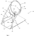
- the golf swing training device 100 includes a hoop 200 positioned above and inclined relative to an operating surface 112 and a carriage 300 coupled to the hoop 200, wherein the carriage 300 includes a club holder 350.
- the golf swing training device 100 delivers the club head square to the ball.
- Existing golf training devices typically incorporate a guide rail or board positioned underneath the shaft of the golf club 400 and do not control movement of the hands of the golfer.
- the club holder 350 of the present disclosure positions the club 400, and thus the hands of the golfer, beneath the plane defined by the circumference of the hoop 200, such that the golfer can obtain the preferred hands position at address with arms dropping vertically from the shoulders, have his/her hands guided on the preferred plane and importantly permit the current invention to guide the shaft into the "laid off" position both on the backswing and follow through.
- the golf swing training device 100 enables a golf player to repeatedly practise and improve his/her golf swing.
- the golf swing training device 100 guides the hands of a user along an intended swing path, from the backswing, through the point of impact, and to the follow through. This results in the user experiencing having his/her hands and a club 400 guided through a well executed golf swing substantially along a single plane.
- the golf swing training device 100 guides the golf club shaft angle from address, through the backswing, into the downswing and then all the way to the top of the follow through, so that the user is in no doubt as to any part of the swing.
- the golf swing training device 100 includes a base 110.
- the base 110 provides an operating surface 112 for the user to stand on.
- the operating surface 112 may include an aperture or other formation for receiving a golf tee (not shown).
- the operating surface 112 may include one or more portions of artificial grass, matting, pad, or other suitable covering from which a golf ball may be struck.
- the operating surface 112 may also include visual markings, such as a centreline marking, or suggested foot position markers, and other alignment markers. Such visual markings may be used to align a user correctly relative to the device 100 and an intended target line.
- the visual markings can be used as reference points by the user, alone or in combination with a golf coach or teaching professional. Such reference points may be particularly useful when used in conjunction with a video recording device for recording instances of the user's swing.
- the golf swing training device 100 of a first embodiment includes a support frame 120, which is secured to and extends upwardly away from the base 110, at an angle of approximately 55 degrees relative to the generally horizontal operating surface 112.
- the support frame 120 includes two generally parallel legs 122, which are each connected to a mounting bracket 124, which is secured to the base 110.
- At least one diagonal or horizontal brace 130 connects the two generally parallel legs 122.
- the diagonal or horizontal brace 130 provides additional stiffness and rigidity.
- a media support unit 140 is mounted to the central portion of the X-shaped formation 132.
- the media support unit 140 enables an electronic media device (not shown) such as a tablet, monitor or laptop to be supported with the screen facing the user. This enables instructional material to be shown to the user before, during, or after practice of the golf swing.
- the electronic media device may be coupled to a video recording device, such as a video camera, to allow a user to record and view swings during a practice session.
- the electronic media device includes a video or still camera.
- the electronic media device may be a tablet computing device that includes a video camera.
- the electronic media device may also be coupled to a launch monitor or other tracking system, such as launch monitors made by Trackman A/S, Flightscope, Accusport, and the like, so that the user can view launch information relating to each swing.
- launch information can include, for example, angle of attack, swing path, spin rate, clubhead speed, ball speed, launch angle, apex, angle of descent, carry, roll, and total distance.
- Coupling of the electronic media device to a video camera or launch monitor may be effected using wired or wireless technologies, including Ethernet, Bluetooth, Wi-Fi, ANT+, and the like.
- each leg 122 is connected to a double ring or hoop 200.
- the hoop 200 includes a first ring 202 and a second ring 204 having a larger diameter, such that the first ring 202 is located concentrically within the second ring 204, and an annular clearance is located between the first and second rings 202, 204.
- a plurality of radially extending spokes 210 extend between and connect the first and second rings 202, 204.
- Each of the first and second rings 202, 204 is generally toroidal, and located in the same plane. However, it will be appreciated that the first and second rings 202, 204 may be manufactured with other cross-sectional profiles. It will be further appreciated that the spokes 210 may be replaced by other coupling devices that maintain the position of the first and second rings 202, 204 relative to one another.
- the hoop 200 may be inclined at an angle relative to a vertical axis by an angle ⁇ , as best seen in Fig. 4 .
- the angle ⁇ is preferably in the range of between about 0 to 20 degrees.
- the hoop 200 has an axis of symmetry, being an axis passing through a central point of the hoop 200, similar to an axle of a wheel.
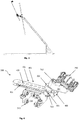
- a first embodiment of a carriage 300 of the golf swing training device 100 is depicted in Figs. 6 to 8 .
- the carriage 300 is operatively associated with the hoop 200, as shown in Figs. 1 to 5 .
- the carriage 300 includes a carriage wedge bracket 302 connected to an arm 304.
- a club holder 350 is located at one end of the arm 304, and a roller dolly 306 is located at a generally opposing end of the carriage 300.
- a plurality of rollers 310 are mounted to the roller dolly 306. As shown in Figs. 7 and 8 , the rollers 310 include a first set of rollers 320 and a second set of rollers 330. The first set of rollers 320 engages with the first, inner ring 202 and the second set of rollers 330 engages with the second, outer ring 204 of the hoop 200. This is schematically depicted in Fig. 7 .
- the rollers 310 are nylon wheeled bearings.
- the interaction between the first and second rings 202, 204 and the first and second sets of rollers 320, 330 results in movement of the roller dolly 306 being restricted to arcuate movement around a circumference of the hoop 200, in a single plane. Accordingly, the roller dolly 306 is prevented from pivoting about an axis defined by a local tangent line intersecting a portion of the hoop 200.
- Each set of rollers 320, 330 preferably has six rollers. However, it will be appreciated that greater than or fewer than six rollers 310 may be utilised in each set of rollers 320, 330. The combination of the two sets of rollers 320, 330 prevents the carriage 300 from being unintentionally removed from the hoop 200.
- the carriage 300 includes a club holder 350 for engaging a shaft of a golf club 400.
- the club holder 350 is adapted to engage an upper portion of the shaft adjacent to a grip portion of the golf club 400.
- the club holder 350 includes an external sleeve 352 and an internal, removable sleeve 354, which is preferably manufactured from an elastically deformable polymer.
- the internal sleeve 354 is a rubber sleeve with a slit along a longitudinal axis, such that the internal sleeve 354 may be slipped onto the shaft of a golf club 400.
- the golf shaft is passed through the external sleeve 352 and the internal sleeve 354 is then fitted to the golf shaft, such that the internal sleeve 354 is located between the shaft of the golf club 400 and the external sleeve 352.
- a plurality of fasteners 360 pass through holes formed in the external sleeve 352, and can be adjusted to apply a force against the external wall of the internal sleeve 354. This permits the golf club 400 to be held in the desired location without damaging the golf club shaft or grip.
- the external sleeve 352 may be rotatable relative to the internal sleeve 354.
- the support frame 120 supports the hoop 200 in such a way that permits the golf club 400 when mounted to the carriage 300 to swing in an unimpeded manner along a controlled path, as directed by the user's hands. During the path of the golf swing, the roller holding dolly 306 remains generally in a single plane. It will be appreciated by a person skilled in the relevant art that other embodiments of the support frame 120 may be envisaged, such as the wall mounted support frame of Fig 14 to 17 .
- the golf swing training device 100 optionally includes one or more means of adjustment that enable the golf swing training device 100 to be customised for a large percentage of potential users.
- Embodiments of the golf swing training device 100 optionally include an adjustment means 401 for varying the radius of the swing arc.
- the adjustment means 401 includes an adjustment plate 402 shown in Fig. 6 .
- the adjustment plate 402 permits the location of the rollers 310 to be adjusted relative to the carriage wedge bracket 302 of the carriage 300, thereby changing the radius of the swing arc.
- the arm 304 of the carriage 300 may be telescopically or otherwise adjustable in length.
- Embodiments of the golf swing training device 100 optionally enable the height of the hoop 200 to be adjustable via the vertical part of the arm 120 sliding up or down in a sleeved base mount.
- Embodiments of the golf swing training device 100 optionally enable the angle of the hoop 200 relative to the generally horizontal operating surface 112 to be variable, such that the angle of the hoop 200 can be set to suit an individual user at an optimised ideal angle to guide the user's hands along the intended swing path, in the backswing, through the point of impact, and the follow through.
- the angle of the hoop 200 is adjusted via spaced holes in bracket 152.
- the golf swing training device 100 does not include a base 100.
- the support frame 120 is adapted to be secured to the ground via mounting brackets, plates, pegs, guy ropes, or other suitable securing devices.
- the support frame is self-supporting, such that the support frame 120 is able to stand upright without a securing device.
- horizontal support members extending back underneath the hoop 200 may be attached to the mounting bracket 124.
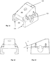
- the wedge bracket 302 is depicted in isolation in Figs. 11 to 13 in perspective, front and side plan views.
- the wedge bracket 302 effectively provides an angular offset of the club holder 350 relative to the roller dolly 306.
- the wedge bracket 302 is pivotally secured to the arm 304, as depicted in Fig. 6 with a pivot pin or bearing 312.
- the wedge bracket 302 is interchangeable, and can readily be replaced with a different wedge bracket 302 having a different angle of inclination y.
- the wedge bracket 302 is mounted on the adjustment plate 402.
- the adjustment plate 402 has a plurality of recesses or notches 403 which are located on two generally parallel, longitudinally extending sides of the adjustment plate 402.
- the wedge bracket 302 includes a pair of clamp jaws 321, seated in openings 323 formed on opposing sides of the wedge bracket 302.
- the clamp jaws 321 are located on opposing sides of the wedge bracket 302, and a screw 322 or other suitable fastener extends between them. By tightening the screw 322, the two clamp jaws 321 are pulled toward each other.
- Each clamp jaw 321 includes a partially cylindrical projection which corresponds in shape with the notches 403.
- the screw 322 may be provided with a knob or handle to obviate the need for tools when making an adjustment.
- the wedge bracket 302 may be provided in different angles ⁇ (See the side view of Fig. 13 ). As such, the user or trainer can readily interchange the wedge bracket 302 to increase or decrease the angle ⁇ to suit different clubs. In one version, not depicted in the drawings, the wedge bracket 302 may be selectively adjustable between different angles ⁇ .
- An underside of the wedge bracket 302 includes two arms or projections 335 which are directed toward each other.
- the arms 335 define a receptacle 332 for receiving the adjustment plate 402.
- the location of the club holder 350 relative to the roller dolly 306 can be adjusted in one of two ways.
- a first adjustment means is provided on account of the adjustment plate 402 being longitudinally moved, by retracting the screw 322 and sliding the adjustment plate 402 longitudinally before re-engaging the screw 322, such that the clamp jaws 321 engage with a different recess 403.
- a second adjustment means is provided on account of the central region of the adjustment plate 402 having a plurality of holes 420 arranged on a common axis, and a fastener extends through at least one of the holes 420 and engages with a body portion 332 of the roller dolly 306.
- the golf swing training device 100 allows small or large adjustment of the club 400 position relative to the hoop 200, and therefore the effective diameter of the hoop 200 from a user point of view, by making an adjustment with respect to one or both of the first and second adjustment means.
- the roller dolly 306 performs this function.
- the second core element is the path that the golf club 400 and, in particular, that the shaft prescribes and it is the wedge bracket 302, the arm 304 and the bolt with bearing 312 that perform this function as follows.
- a longitudinal portion of the arm 304 is generally parallel to a plane passing through both rings of the dual hoops 200 when the club 400 is located in an initial, address position.
- the longitudinal portion of the arm 304 becomes angularly inclined relative to the plane passing through both rings of the dual hoops 200.
- the angle formed between the shaft of a six iron and the ground is approximately 60 degrees. If the club 400 is rotated about the wedge bracket 302, through an angle of 180 degrees, such that the club head becomes the highest portion of the club 400, the club 400 is subsequently oriented such that the angle between the shaft and the ground is again approximately 60 degrees. In so doing the club 400 and the club shaft angle is precisely guided along the prescribed ideal path throughout the total swing, while the roller dolly 306 keeps the hands tracking on the ideal swing plane of about 80 degrees.
- a desired golf club 400 such as a 5 or 6 iron, is fitted to the carriage 300, and secured in the manner described above.
- the vertical height of the grip portion of the golf club 400 may be adjusted within the carriage 300 to suit specific dimensions, such as height and arm length of the user. This may be done by making an adjustment of the golf club 400 relative to the internal sleeve 354.
- the two generally parallel legs 122 of the support frame 120 can be selectively telescopically adjustable vertically, or otherwise extensible or angularly adjustable to alter the vertical position of the hoop 200.
- a player stands on the operating surface 112, and takes grip of the golf club.
- the head and shoulders of the player are inserted through the central opening formed in the hoop 200, as depicted schematically in Fig. 3 .
- the player's hand grip is located adjacent to the roller dolly 306. This means that during rotation through the golf swing, the arc that the user's hands follow corresponds generally to the arc defined by the hoop 200.
- the hoop 200 provides a track along which the roller dolly 306 of the carriage 300 is permitted to run freely, and smoothly.
- the roller dolly 306 is forced to maintain a consistent and predetermined angular orientation during rotation, relative to a plane passing through the first and second rings 202, 204.
- the arm 304 is pivotally secured to the wedge bracket 302, with a pin or shaft 312 as depicted in Fig. 6 .
- the shaft 312 enables the arm 304 to swing or pivot relative to the wedge portion 302 during rotation about the hoop 200, about an axis which is generally perpendicular to a plane passing through the first and second rings 202, 204.
- a mounting collar 370 is coupled to each end of the external sleeve 352 and is nylon lined and grooved to limit the rotation of the external sleeve.
- the mounting collar 370 is adapted to limit rotation of the external sleeve 352 to approximately 45 degrees clockwise and 22.5 degrees anticlockwise, by using a pin and groove design. Such rotation of the external sleeve 352 occurs about a longitudinal axis of the shaft of the golf club 400.
- a pair of bearings 362 enable the inner sleeve 354 to pivot relative to the external sleeve 352.
- the user is permitted to rotate the golf club 400 up to 45 degrees at the end of the downswing (follow through), and up to 45 degrees at the top of the backswing.
- the carriage 300 promotes the club head returning back to square at impact on a slightly in-to-out path.
- Such an in-to-out path is desirable as it promotes a golf shot with a slight draw, from right to left for a right-handed player, and from left to right for a left handed player.
- the user may watch educational material, such as a video shown on a tablet or laptop computer or other electronic media device mounted on the media support unit 140.
- an electronic media device may be coupled to a launch monitor, so that launch information is able to be displayed on a screen of the electronic media device.
- a video of the player may be displayed adjacent to or overlaid by a video of a professional golfer.
- the analysis device may measure data relating to the club and/or the swing and may be implemented, for example, using a video camera, SkyPro by SkyGolf, MySwing by noisytom, SwingSmart, Zepp, SwingTip, 3Bays Golf Swing Analyzer, or any other golf swing analyser.
- the analysis device is optionally configurable to connect via a wired or wireless connection to an electronic media device located in the media support unit 140.
- the carriage 300 holds the golf club 400 close to the user's grip, such that the user's hands are directly opposite the carriage 300 on the dual hoop 200.
- the user is guided to achieve the desirable predetermined path and swing plane.
- the hoop 200 is located above the user's hands and the shaft of the golf club 400, thereby permitting the golf club 400 to be laid off during the backswing, the downswing and the follow through and for the user's hands and club to be genuinely guided along the same or a similar path that would be taken by many professional golfers.
- the golf swing training device 100 assists in building consistency and accuracy in a player's swing.
- the golf swing training device 100 guides the golfer's hands and club 400 in a way that mimics the swing of typical professional tour golfers.
- the golf swing training device 100 permits the user to groove in the correct swing by repetition, every day if desired. It is well known that even after a series of lessons, most golfers revert to their original bad habits after a month or two or, even worse, practise inaccurately and ingrain a poor swing path. Most professional golfers have a coach who is responsible for ensuring that bad habits do not creep in. This training device has the potential to fill the same role as the coach of a professional golfer.
- FIG. 23 to 25 A second embodiment of the golf swing training device 1000 is depicted in Figs. 23 to 25 .
- Like reference numerals are used to denote features which are unchanged between the first and second embodiments, and the following description is focussed primarily on the differences.
- the length of the arm 304 is greater.
- the arm 304 is pivotal about the shaft 334.
- Figs. 18 to 22 show a putting attachment 600 for use with the golf swing training device 100, for training a user's putting technique.
- the putting attachment 600 holds or retains any putter 402 and similarly guides the hands along the line of the intended putt both in the backswing and the follow through. This is achieved by adjusting the hoop 200 angle to 90 degrees to the floor so that the carriage 300 follows this line and, consequently so do the player's hands.
- the putting attachment 600 permits any putter 402 shaft to be set at the manufacturers intended angle, on account of the pivot connection 602 that is easily adjusted by hand, by loosening then adjusting the club 402 shaft angle, then tightening knob 604.
- the putting attachment 600 utilises a putter bracket 610 which is generally flat (as opposed to the wedge bracket 302), as shown in detail in Figs. 21 and 22 .
- the putting attachment 600 is used with the standard carriage assembly 300 described above.
- the putter bracket 610 engages with the adjustment plate 402, and may be adjusted in the manner outlined above with respect to the wedge bracket 302.
- the knob 604 is secured to a pair of opposing clamp plates 608 which secure a clip 609 around the shaft of the putter 402.
- the third element of the technique that has been adopted by many touring professional golfers is that the stroke is performed with a rocking shoulder/arm action, with nil or very little movement in the wrists. In other words the wrists remain firm throughout the stroke.
- the present disclosure guides the player precisely in each of the above elements.
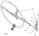
- Figs. 14 to 17 depict a wall mounting assembly 500 for use with the golf swing training device 100.
- the wall mounting assembly 500 includes a pair of wall securement members 502.
- the wall securement members 502 are secured to a wall or other generally vertical surface with suitable fasteners, such as masonry anchors or coach screws, depending on the material that the wall is fabricated from.
- the hoop 200 is generally parallel with the wall and is located in proximity to the wall. This provides space saving advantages when not in use.
- each of the pair of pivot arms 504 pivots about a pin 506.
- a distal end of each arm 504 has a projection 511 which extends into a slot 512 formed within a hoop mounting arm 550.
- the projection 511 reaches the end of the slot 512, the range of angular motion of the hoop mounting arm 550 is restricted, and this defines the second, in use configuration.
- the wall mounting unit 500 is based on a three bar linkage system.
- the golf swing training device 100 permits the player to practice the correct swing in slow motion. The reason this is important is because a typical swing takes about 2 seconds. In this time a player can only work on one, perhaps two thoughts, whereas there are usually 5 or 6 issues that need to be addressed - such as flat wrist at top, on the downswing - shoulders moving under & through, not around or towards the front, right elbow tucking into the right side on the downswing, releasing the club head as the hands pass the right thigh i.e. as late as possible for maximum acceleration through the ball, no lateral body movement in backswing, head steady and no lateral movement in follow through, club shaft creating the same plane on the follow through as it did on the backswing.
- each of these issues can be corrected in one swing, then gradually implemented into the players swing with just a few minutes each day on the trainer.
- the golf swing training device 100 guides the player correctly through each of the above movements/actions.
- the golf swing training device 100 is suitable for either right or left handed players.
- the golf swing training device 100 may be sold with either or both of the wall mounting unit 500 or the floor mounted base 110 and support frame 120, depending on user preference.
- the components of the golf swing training device 100 may be fabricated from metal, or plastic (via plastic injection moulding or another suitable forming process).
- the golf swing training device 100 locates the hoop 200 above the user's hands. This prevents the hoop 200 position from interfering with the club shaft during the backswing, the downswing and the follow through. In existing golf swing training devices, the hoop is not located above the user's hands, thereby preventing the club from taking the correct swing plane by interfering with the club shaft on both backswing and follow through.
- the second embodiment of the invention when used with the wall mounting assembly 500 can be folded away when not in use, for space saving and storage purposes.
Landscapes
- Engineering & Computer Science (AREA)
- General Health & Medical Sciences (AREA)
- Health & Medical Sciences (AREA)
- Physical Education & Sports Medicine (AREA)
- Business, Economics & Management (AREA)
- Mechanical Engineering (AREA)
- Physics & Mathematics (AREA)
- Entrepreneurship & Innovation (AREA)
- Educational Administration (AREA)
- Educational Technology (AREA)
- General Physics & Mathematics (AREA)
- Theoretical Computer Science (AREA)
- Golf Clubs (AREA)
- Rehabilitation Tools (AREA)
Claims (23)
- Golfschwungübungsvorrichtung, umfassend:einen Reifen (200), der über und geneigt zu einem Untergrund (112) angeordnet ist;einen Stützrahmen (120), der mit dem Reifen (200) verbunden ist, um diesen zu stützen; undeinen Schlitten (300) mit einem Körperabschnitt, einer mit dem Körperabschnitt schwenkbar verbundenen Schlägerhalterung (350) und einem mit dem Körperabschnitt verbundenen Rollblock (306), wobei der Rollblock (306) an dem Reifen (200) befestigt und um den Umfang des Reifens herum drehbar ist;wobei eine Schlägerschaftlängsachse der Schlägerhalterung (350) winkelig versetzt relativ zu einer sich senkrecht zu einer Symmetrieachse des Reifens erstrechenden Reifenebene verläuft;wobei die Schlägerhalterung (350) auf der Seite des Reifens angeordnet ist, an der ein Benutzer der Golfschwungübungsvorrichtung in Bezug auf den Reifen (200) steht;dadurch gekennzeichnet, dassder Rollblock (360) und/der der Schlittenkörperabschnitt verstellbar ist/sind, um selektiv einen Radius eines Bogens, den eine Hand des Benutzers beschreibt, zu ändern.
- Golfschwungübungsvorrichtung gemäß Anspruch 1, die des Weiteren eine zwischen dem Körperabschnitt und der Schlägerhalterung (350) angeordnete Keilklemme (302) aufweist, wobei die Keilklemme (302) selektiv austauschbar oder verstellbar ist, um den Winkelversatz der Schlägerschaftlängsachse relativ zu der Reifenebene zu verändern.
- Golfschwungübungsvorrichtung gemäß Anspruch 2, wobei die Schlägerschaftlängsachse im Wesentlichen senkrecht zu einer Schwenkachse verläuft, um die die Schlägerhalterung (350) schwenkbar mit der Keilklemme (302) verbunden ist, wobei die Golfschwungübungsvorrichtung des Weiteren einen Schlägerhalterungsarm (304) mit einem schwenkbaren mit einer geneigten Oberfläche der Keilklemme (302) verbundenen proximalen End und einem mit der Schlägerhalterung (350) verbundenem distalen End aufweist.
- Golfschwungübungsvorrichtung gemäß einem der vorhergehenden Ansprüche, wobei der Reifen (200) einen ersten Ring (202) und einen zweiten Ring (204), dessen Durchmesser größer als der des konzentrisch in dem zweiten Ring (204) angeordneten ersten Ringes (202) ist, aufweist.
- Golfschwungübungsvorrichtung gemäß Anspruch 4, wobei der erste Ring und der zweite Ring (202, 204) jeweils toroidal im Querschnitt und koplanar sind.
- Golfschwungübungsvorrichtung gemäß Anspruch 4 oder 5, wobei sich zwischen dem ersten Ring und dem zweiten Ring (202, 204) ein ringförmiger Spalt befindet.
- Golfschwungübungsvorrichtung gemäß einem der Ansprüche 2 bis 6, wobei der Rollblock (306) eine Mehrzahl von Rollen (310) aufweist, die dazu ausgebildet sind, mit dem ersten und dem zweiten Ring (202, 204) in Eingriff zu gelangen.
- Golfschwungübungsvorrichtung gemäß Anspruch 7, die einen ersten Satz von mit dem ersten Ring (202) in Eingriff stehenden Rollen (320) und einen zweiten Satz von mit dem zweiten Ring (204) in Eingriff stehenden Rollen (330) aufweist.
- Golfschwungübungsvorrichtung gemäß Anspruch 8, wobei der erste und der zweite Rollensatz (320, 330) und der erste und der zweite Ring (202, 204) die Bewegung des Rollblocks (306) auf eine bogenförmige Bewegung um den Umfang des Reifens (200) in einer einzigen Ebene begrenzen.
- Golfschwungübungsvorrichtung gemäß Anspruch 1, wobei der Rollblock (306) schwenkbar relativ zu dem Körperabschnitt des Schlittens (300) ausgebildet ist.
- Golfschwungübungsvorrichtung gemäß Anspruch 10, wobei der Rollblock (306) mit dem Körperabschnitt des Schlittens (300) über eine Achse (334) gekoppelt ist.
- Golfschwungübungsvorrichtung gemäß einem der vorhergehenden Ansprüche, wobei die Schlägerhalterung (350) dazu ausgebildet ist, einen Golfschläger (400) derart schwenkbar zu haltern, dass der Golfschläger (400) um eine Golfschlägerlängsachse schwenkbar ist.
- Golfschwungübungsvorrichtung gemäß Anspruch 12, wobei die Golfschlägerhalterung eine äußere Manschette (352) und eine innere Manschette (354) aufweist, die dazu ausgebildet sind, einen Abschnitt des Golfschlägerschafts (400) aufzunehmen und an diesem anzuliegen, wobei die innere Manschette (354) drehbar relativ zu der äußeren Manschette (352) ausgebildet ist.
- Golfschwungübungsvorrichtung gemäß einem der vorhergehenden Ansprüche, wobei ein Griffbereich des Griffs des Golfschlägers (400) benachbart zu dem Rollblock (306) derart angeordnet ist, das bei Gebrauch die Hände des Benutzers so ausgerichtet sind, dass sie einem Bogen folgen, der im Wesentlichen dem Bogen entspricht, dem die Rollen folgen.
- Golfschwungübungsvorrichtung gemäß einem der vorhergehenden Ansprüche, umfassend eine an dem Stützrahmen befestigte Medienhalterungseinheit (140).
- Golfschwungübungsvorrichtung gemäß Anspruch 2, wobei die Keilklemme (302) auf einer Halteplatte befestigt ist, wobei die Keilklemme (302) selektiv relativ zu einer Längsachse der Halteplatte bewegbar ist, um den Radius des Rotationsbogens der Schlägerhalterung (350) einzustellen.
- Golfschwungübungsvorrichtung gemäß Anspruch 16, wobei die Halteplatte an dem Schlittenkörperabschnitt befestig ist und die Halteplatte selektiv relativ zu dem Körperabschnitt des Schlittens bewegbar ist, um den Radius des Rotationsbogens der Schlägerhalterung (350) einzustellen.
- Golfschwungübungsvorrichtung gemäß einem der vorhergehenden Ansprüche, die des Weiteren einen Verlängerungsarm (304) aufweist, der zwischen der Schlägerhalterung und dem Rollblock (306) derart angeordnet ist, dass die Schlägerhalterung unterhalb eines untersten Abschnitts des Reifens (200) angeordnet ist, wenn sich die Schlägerhalterung in der Ansprechposition befindet.
- Golfschwungübungsvorrichtung gemäß Anspruch 18, wobei der Verlängerungsarm (304) schwenkbar an der Keilklemme (302) befestigt ist.
- Golfschwungübungsvorrichtung gemäß einem der vorhergehenden Ansprüche, die eine Wandbefestigungsanordnung (500) zur Befestigung des Reifens (200) an einer Wand oder anderen Oberfläche aufweist.
- Golfschwungübungsvorrichtung gemäß Anspruch 20, wobei die Wandbefestigungsanordnung (500) umfasst:wenigstens ein Wandbefestigungselement (502) zur Befestigung an einer Wand oder anderen Oberfläche;einen Schwenkarm (504) mit einem proximalen Ende, das schwenkbar an dem Wandbefestigungselement (502) befestig ist, und einem distalen Ende; undeinen Reifenbefestigungsarm (550) mit einem proximalen Ende, das schwenkbar an dem Wandbefestigungselement (502) befestigt ist, und einem distalen Ende, das schwenkbar an dem Reifen (200) befestigt ist,wobei das distale Ende des Schwenkarms (504) einen Vorsprung (511) aufweist, der in einen entsprechenden in dem Reifenbefestigungsarm (550) ausgebildeten Längsschlitz eingreift.
- Golfschwungübungsvorrichtung gemäß Anspruch 21, wobei bei einer Befestigung an einer Wand oder einer anderen im Wesentlichen vertikalen Oberfläche das proximale Ende des Reifenbefestigungsarms vertikal unterhalb des proximalen Endes de Schwenkarms angeordnet ist.
- Golfschwungübungsvorrichtung gemäß Anspruch 1, die des Weiteren eine zwischen dem Körperabschnitt und der Schlägerhalterung angeordneten Putter-Klemme (610) aufweist, wobei die Putter-Klemme (610) verstellbar mit der Schlägerhalterung derart verbunden ist, dass der Winkelversatz der Schlägerschaftlängsachse relativ zur Reifenebene selektiv veränderbar ist.
Applications Claiming Priority (3)
| Application Number | Priority Date | Filing Date | Title |
|---|---|---|---|
| AU2014904922A AU2014904922A0 (en) | 2014-12-05 | Golf swing training device | |
| AU2015903664A AU2015903664A0 (en) | 2015-09-08 | Golf swing training device | |
| PCT/AU2015/050770 WO2016086277A1 (en) | 2014-12-05 | 2015-12-04 | Golf swing training device |
Publications (3)
| Publication Number | Publication Date |
|---|---|
| EP3226986A1 EP3226986A1 (de) | 2017-10-11 |
| EP3226986A4 EP3226986A4 (de) | 2018-08-15 |
| EP3226986B1 true EP3226986B1 (de) | 2020-02-12 |
Family
ID=56090743
Family Applications (1)
| Application Number | Title | Priority Date | Filing Date |
|---|---|---|---|
| EP15864652.1A Active EP3226986B1 (de) | 2014-12-05 | 2015-12-04 | Golfschwungübungsvorrichtung |
Country Status (8)
| Country | Link |
|---|---|
| US (1) | US10258858B2 (de) |
| EP (1) | EP3226986B1 (de) |
| JP (1) | JP6753864B2 (de) |
| CN (1) | CN106999758B (de) |
| AU (1) | AU2015358300B2 (de) |
| NZ (1) | NZ732207A (de) |
| WO (1) | WO2016086277A1 (de) |
| ZA (1) | ZA201704152B (de) |
Families Citing this family (5)
| Publication number | Priority date | Publication date | Assignee | Title |
|---|---|---|---|---|
| USD983915S1 (en) * | 2021-02-03 | 2023-04-18 | Bradley R. Mason | Flattened ring-shaped golf alignment stick stand |
| USD983297S1 (en) * | 2021-02-03 | 2023-04-11 | Bradley R. Mason | Ring-shaped golf alignment stick stand |
| USD984571S1 (en) * | 2021-02-03 | 2023-04-25 | Bradley R. Mason | Disc-shaped golf alignment stick stand |
| CN113674598B (zh) * | 2021-07-21 | 2023-05-26 | 深圳市踏奇空间科技有限公司 | 一种模拟晶状体变形近视用仿生眼球教具 |
| US20250205550A1 (en) * | 2023-12-22 | 2025-06-26 | Golftec Enterprises Llc | Systems and methods for single mobile device launch monitor and motion capture |
Family Cites Families (19)
| Publication number | Priority date | Publication date | Assignee | Title |
|---|---|---|---|---|
| US1567530A (en) | 1924-04-02 | 1925-12-29 | Ronald G Macnaughton | Golf swing device |
| US4034991A (en) * | 1974-03-18 | 1977-07-12 | Jess Oppenheimer | Swing training apparatus |
| GB2039221B (en) * | 1978-11-17 | 1982-09-22 | Richards R | Golf swing simulator |
| JPS5957971U (ja) * | 1982-10-07 | 1984-04-16 | 並木 清一 | ゴルフ練習装置 |
| GB8724226D0 (en) * | 1987-10-15 | 1987-11-18 | Higginson N | Golf training apparatus |
| GB9019055D0 (en) * | 1990-08-31 | 1990-10-17 | Higginson Norman | Golf training apparatus |
| US5072942A (en) * | 1990-09-21 | 1991-12-17 | Swing Right Manufacturing Inc. | Golf swing training device |
| US5242344A (en) * | 1990-10-31 | 1993-09-07 | Hundley Kenneth W | Limb movement exercising and training apparatus |
| US5595545A (en) | 1995-10-03 | 1997-01-21 | Track Trainer, Inc. | Golf swing training track apparatus |
| KR100419956B1 (ko) * | 2001-07-03 | 2004-02-25 | 조진형 | 골프의 스윙 연습장치 |
| US20080153618A1 (en) * | 2006-11-17 | 2008-06-26 | Callaway Golf Company | Golf swing training system, method and device |
| WO2009007903A2 (en) * | 2007-07-06 | 2009-01-15 | Xemp Golfing Technologies Cc | Golf teaching apparatus |
| US8974316B2 (en) * | 2010-04-22 | 2015-03-10 | Joseph Sery | Putting/chipping trainer |
| DE102010052670A1 (de) * | 2010-11-26 | 2012-05-31 | Robert Wolf | Vorrichtung und Verfahren zum Trainieren des Golfschwungs |
| KR101212883B1 (ko) * | 2011-06-17 | 2013-01-09 | 김대영 | 골프 타격 연습기 |
| US8591349B1 (en) * | 2011-06-22 | 2013-11-26 | Herman L. Jones | Putting training device |
| US8715098B2 (en) * | 2011-09-14 | 2014-05-06 | David Napolitano | Golf swing training device |
| CN202751764U (zh) * | 2012-08-03 | 2013-02-27 | 段宝永 | 高尔夫挥杆平面训练器 |
| CN104127997B (zh) * | 2014-07-15 | 2017-02-08 | 中山市迈进高尔夫用品有限公司 | 练习高尔夫球挥杆动作的健身器材 |
-
2015
- 2015-12-04 CN CN201580066267.3A patent/CN106999758B/zh active Active
- 2015-12-04 US US15/531,928 patent/US10258858B2/en active Active
- 2015-12-04 NZ NZ732207A patent/NZ732207A/en unknown
- 2015-12-04 EP EP15864652.1A patent/EP3226986B1/de active Active
- 2015-12-04 AU AU2015358300A patent/AU2015358300B2/en active Active
- 2015-12-04 JP JP2017548502A patent/JP6753864B2/ja active Active
- 2015-12-04 WO PCT/AU2015/050770 patent/WO2016086277A1/en not_active Ceased
-
2017
- 2017-06-15 ZA ZA2017/04152A patent/ZA201704152B/en unknown
Non-Patent Citations (1)
| Title |
|---|
| None * |
Also Published As
| Publication number | Publication date |
|---|---|
| EP3226986A1 (de) | 2017-10-11 |
| AU2015358300B2 (en) | 2018-05-10 |
| JP2018504251A (ja) | 2018-02-15 |
| ZA201704152B (en) | 2019-05-29 |
| NZ732207A (en) | 2018-06-29 |
| CN106999758B (zh) | 2020-04-03 |
| US20170259151A1 (en) | 2017-09-14 |
| CN106999758A (zh) | 2017-08-01 |
| US10258858B2 (en) | 2019-04-16 |
| AU2015358300A1 (en) | 2017-06-15 |
| EP3226986A4 (de) | 2018-08-15 |
| JP6753864B2 (ja) | 2020-09-09 |
| WO2016086277A1 (en) | 2016-06-09 |
Similar Documents
| Publication | Publication Date | Title |
|---|---|---|
| US9283463B2 (en) | Golf swing training apparatus | |
| USRE47332E1 (en) | Golf training system and method | |
| US10258858B2 (en) | Golf swing training device | |
| US8715098B2 (en) | Golf swing training device | |
| US20070275788A1 (en) | Method and apparatus for training a golf swing | |
| US8277331B2 (en) | Golf training method and apparatus | |
| JP2022000273A (ja) | スポーツトレーニング補助具 | |
| US20150217175A1 (en) | Multipurpose golf training aid | |
| US8088018B2 (en) | Golf aid | |
| US9707464B2 (en) | Golf club training aid and golf club | |
| US20130244804A1 (en) | Golf Swing Training Device | |
| US7846035B2 (en) | Golf swing exercising/training apparatus and associated method | |
| WO2009007903A2 (en) | Golf teaching apparatus | |
| US20100216562A1 (en) | Golf teaching apparatus | |
| US7641567B2 (en) | Gold putting training apparatus and method | |
| KR200425800Y1 (ko) | 골프연습용 스윙교정장치 | |
| KR200397928Y1 (ko) | 퍼팅용 골프채 및 그 퍼팅교정구 | |
| US11745074B1 (en) | Golf swing training aid | |
| JP2814199B2 (ja) | ゴルフスイング練習装置 | |
| JP2541528Y2 (ja) | ゴルフスイング練習機 | |
| KR20100018172A (ko) | 골프 연습용 보조기구 및 이를 이용한 연습 방법 | |
| JP3192606U (ja) | ゴルフスイング練習装置 | |
| KR19980059471U (ko) | 골프의 퍼팅 및 스윙연습장치 | |
| JP2003126320A (ja) | アドレス補正ゴルフ練習器 | |
| JP2005329259A (ja) | パタ−プログレス装置 |
Legal Events
| Date | Code | Title | Description |
|---|---|---|---|
| STAA | Information on the status of an ep patent application or granted ep patent |
Free format text: STATUS: THE INTERNATIONAL PUBLICATION HAS BEEN MADE |
|
| PUAI | Public reference made under article 153(3) epc to a published international application that has entered the european phase |
Free format text: ORIGINAL CODE: 0009012 |
|
| STAA | Information on the status of an ep patent application or granted ep patent |
Free format text: STATUS: REQUEST FOR EXAMINATION WAS MADE |
|
| 17P | Request for examination filed |
Effective date: 20170630 |
|
| AK | Designated contracting states |
Kind code of ref document: A1 Designated state(s): AL AT BE BG CH CY CZ DE DK EE ES FI FR GB GR HR HU IE IS IT LI LT LU LV MC MK MT NL NO PL PT RO RS SE SI SK SM TR |
|
| AX | Request for extension of the european patent |
Extension state: BA ME |
|
| DAV | Request for validation of the european patent (deleted) | ||
| DAX | Request for extension of the european patent (deleted) | ||
| A4 | Supplementary search report drawn up and despatched |
Effective date: 20180716 |
|
| RIC1 | Information provided on ipc code assigned before grant |
Ipc: A63B 69/36 20060101AFI20180710BHEP |
|
| GRAP | Despatch of communication of intention to grant a patent |
Free format text: ORIGINAL CODE: EPIDOSNIGR1 |
|
| STAA | Information on the status of an ep patent application or granted ep patent |
Free format text: STATUS: GRANT OF PATENT IS INTENDED |
|
| INTG | Intention to grant announced |
Effective date: 20191029 |
|
| GRAS | Grant fee paid |
Free format text: ORIGINAL CODE: EPIDOSNIGR3 |
|
| GRAA | (expected) grant |
Free format text: ORIGINAL CODE: 0009210 |
|
| STAA | Information on the status of an ep patent application or granted ep patent |
Free format text: STATUS: THE PATENT HAS BEEN GRANTED |
|
| AK | Designated contracting states |
Kind code of ref document: B1 Designated state(s): AL AT BE BG CH CY CZ DE DK EE ES FI FR GB GR HR HU IE IS IT LI LT LU LV MC MK MT NL NO PL PT RO RS SE SI SK SM TR |
|
| REG | Reference to a national code |
Ref country code: GB Ref legal event code: FG4D |
|
| REG | Reference to a national code |
Ref country code: CH Ref legal event code: EP |
|
| REG | Reference to a national code |
Ref country code: AT Ref legal event code: REF Ref document number: 1231313 Country of ref document: AT Kind code of ref document: T Effective date: 20200215 |
|
| REG | Reference to a national code |
Ref country code: IE Ref legal event code: FG4D |
|
| REG | Reference to a national code |
Ref country code: DE Ref legal event code: R096 Ref document number: 602015047066 Country of ref document: DE |
|
| PG25 | Lapsed in a contracting state [announced via postgrant information from national office to epo] |
Ref country code: RS Free format text: LAPSE BECAUSE OF FAILURE TO SUBMIT A TRANSLATION OF THE DESCRIPTION OR TO PAY THE FEE WITHIN THE PRESCRIBED TIME-LIMIT Effective date: 20200212 Ref country code: FI Free format text: LAPSE BECAUSE OF FAILURE TO SUBMIT A TRANSLATION OF THE DESCRIPTION OR TO PAY THE FEE WITHIN THE PRESCRIBED TIME-LIMIT Effective date: 20200212 Ref country code: NO Free format text: LAPSE BECAUSE OF FAILURE TO SUBMIT A TRANSLATION OF THE DESCRIPTION OR TO PAY THE FEE WITHIN THE PRESCRIBED TIME-LIMIT Effective date: 20200512 |
|
| REG | Reference to a national code |
Ref country code: LT Ref legal event code: MG4D |
|
| REG | Reference to a national code |
Ref country code: NL Ref legal event code: MP Effective date: 20200212 |
|
| PG25 | Lapsed in a contracting state [announced via postgrant information from national office to epo] |
Ref country code: BG Free format text: LAPSE BECAUSE OF FAILURE TO SUBMIT A TRANSLATION OF THE DESCRIPTION OR TO PAY THE FEE WITHIN THE PRESCRIBED TIME-LIMIT Effective date: 20200512 Ref country code: LV Free format text: LAPSE BECAUSE OF FAILURE TO SUBMIT A TRANSLATION OF THE DESCRIPTION OR TO PAY THE FEE WITHIN THE PRESCRIBED TIME-LIMIT Effective date: 20200212 Ref country code: SE Free format text: LAPSE BECAUSE OF FAILURE TO SUBMIT A TRANSLATION OF THE DESCRIPTION OR TO PAY THE FEE WITHIN THE PRESCRIBED TIME-LIMIT Effective date: 20200212 Ref country code: HR Free format text: LAPSE BECAUSE OF FAILURE TO SUBMIT A TRANSLATION OF THE DESCRIPTION OR TO PAY THE FEE WITHIN THE PRESCRIBED TIME-LIMIT Effective date: 20200212 Ref country code: IS Free format text: LAPSE BECAUSE OF FAILURE TO SUBMIT A TRANSLATION OF THE DESCRIPTION OR TO PAY THE FEE WITHIN THE PRESCRIBED TIME-LIMIT Effective date: 20200612 Ref country code: GR Free format text: LAPSE BECAUSE OF FAILURE TO SUBMIT A TRANSLATION OF THE DESCRIPTION OR TO PAY THE FEE WITHIN THE PRESCRIBED TIME-LIMIT Effective date: 20200513 |
|
| PG25 | Lapsed in a contracting state [announced via postgrant information from national office to epo] |
Ref country code: NL Free format text: LAPSE BECAUSE OF FAILURE TO SUBMIT A TRANSLATION OF THE DESCRIPTION OR TO PAY THE FEE WITHIN THE PRESCRIBED TIME-LIMIT Effective date: 20200212 |
|
| PG25 | Lapsed in a contracting state [announced via postgrant information from national office to epo] |
Ref country code: SK Free format text: LAPSE BECAUSE OF FAILURE TO SUBMIT A TRANSLATION OF THE DESCRIPTION OR TO PAY THE FEE WITHIN THE PRESCRIBED TIME-LIMIT Effective date: 20200212 Ref country code: DK Free format text: LAPSE BECAUSE OF FAILURE TO SUBMIT A TRANSLATION OF THE DESCRIPTION OR TO PAY THE FEE WITHIN THE PRESCRIBED TIME-LIMIT Effective date: 20200212 Ref country code: SM Free format text: LAPSE BECAUSE OF FAILURE TO SUBMIT A TRANSLATION OF THE DESCRIPTION OR TO PAY THE FEE WITHIN THE PRESCRIBED TIME-LIMIT Effective date: 20200212 Ref country code: EE Free format text: LAPSE BECAUSE OF FAILURE TO SUBMIT A TRANSLATION OF THE DESCRIPTION OR TO PAY THE FEE WITHIN THE PRESCRIBED TIME-LIMIT Effective date: 20200212 Ref country code: RO Free format text: LAPSE BECAUSE OF FAILURE TO SUBMIT A TRANSLATION OF THE DESCRIPTION OR TO PAY THE FEE WITHIN THE PRESCRIBED TIME-LIMIT Effective date: 20200212 Ref country code: LT Free format text: LAPSE BECAUSE OF FAILURE TO SUBMIT A TRANSLATION OF THE DESCRIPTION OR TO PAY THE FEE WITHIN THE PRESCRIBED TIME-LIMIT Effective date: 20200212 Ref country code: CZ Free format text: LAPSE BECAUSE OF FAILURE TO SUBMIT A TRANSLATION OF THE DESCRIPTION OR TO PAY THE FEE WITHIN THE PRESCRIBED TIME-LIMIT Effective date: 20200212 Ref country code: PT Free format text: LAPSE BECAUSE OF FAILURE TO SUBMIT A TRANSLATION OF THE DESCRIPTION OR TO PAY THE FEE WITHIN THE PRESCRIBED TIME-LIMIT Effective date: 20200705 Ref country code: ES Free format text: LAPSE BECAUSE OF FAILURE TO SUBMIT A TRANSLATION OF THE DESCRIPTION OR TO PAY THE FEE WITHIN THE PRESCRIBED TIME-LIMIT Effective date: 20200212 |
|
| REG | Reference to a national code |
Ref country code: DE Ref legal event code: R097 Ref document number: 602015047066 Country of ref document: DE |
|
| REG | Reference to a national code |
Ref country code: AT Ref legal event code: MK05 Ref document number: 1231313 Country of ref document: AT Kind code of ref document: T Effective date: 20200212 |
|
| PLBE | No opposition filed within time limit |
Free format text: ORIGINAL CODE: 0009261 |
|
| STAA | Information on the status of an ep patent application or granted ep patent |
Free format text: STATUS: NO OPPOSITION FILED WITHIN TIME LIMIT |
|
| 26N | No opposition filed |
Effective date: 20201113 |
|
| PG25 | Lapsed in a contracting state [announced via postgrant information from national office to epo] |
Ref country code: AT Free format text: LAPSE BECAUSE OF FAILURE TO SUBMIT A TRANSLATION OF THE DESCRIPTION OR TO PAY THE FEE WITHIN THE PRESCRIBED TIME-LIMIT Effective date: 20200212 Ref country code: IT Free format text: LAPSE BECAUSE OF FAILURE TO SUBMIT A TRANSLATION OF THE DESCRIPTION OR TO PAY THE FEE WITHIN THE PRESCRIBED TIME-LIMIT Effective date: 20200212 |
|
| PG25 | Lapsed in a contracting state [announced via postgrant information from national office to epo] |
Ref country code: SI Free format text: LAPSE BECAUSE OF FAILURE TO SUBMIT A TRANSLATION OF THE DESCRIPTION OR TO PAY THE FEE WITHIN THE PRESCRIBED TIME-LIMIT Effective date: 20200212 Ref country code: PL Free format text: LAPSE BECAUSE OF FAILURE TO SUBMIT A TRANSLATION OF THE DESCRIPTION OR TO PAY THE FEE WITHIN THE PRESCRIBED TIME-LIMIT Effective date: 20200212 |
|
| REG | Reference to a national code |
Ref country code: CH Ref legal event code: PL |
|
| PG25 | Lapsed in a contracting state [announced via postgrant information from national office to epo] |
Ref country code: MC Free format text: LAPSE BECAUSE OF FAILURE TO SUBMIT A TRANSLATION OF THE DESCRIPTION OR TO PAY THE FEE WITHIN THE PRESCRIBED TIME-LIMIT Effective date: 20200212 |
|
| REG | Reference to a national code |
Ref country code: BE Ref legal event code: MM Effective date: 20201231 |
|
| PG25 | Lapsed in a contracting state [announced via postgrant information from national office to epo] |
Ref country code: LU Free format text: LAPSE BECAUSE OF NON-PAYMENT OF DUE FEES Effective date: 20201204 Ref country code: IE Free format text: LAPSE BECAUSE OF NON-PAYMENT OF DUE FEES Effective date: 20201204 |
|
| PG25 | Lapsed in a contracting state [announced via postgrant information from national office to epo] |
Ref country code: LI Free format text: LAPSE BECAUSE OF NON-PAYMENT OF DUE FEES Effective date: 20201231 Ref country code: CH Free format text: LAPSE BECAUSE OF NON-PAYMENT OF DUE FEES Effective date: 20201231 |
|
| PG25 | Lapsed in a contracting state [announced via postgrant information from national office to epo] |
Ref country code: TR Free format text: LAPSE BECAUSE OF FAILURE TO SUBMIT A TRANSLATION OF THE DESCRIPTION OR TO PAY THE FEE WITHIN THE PRESCRIBED TIME-LIMIT Effective date: 20200212 Ref country code: MT Free format text: LAPSE BECAUSE OF FAILURE TO SUBMIT A TRANSLATION OF THE DESCRIPTION OR TO PAY THE FEE WITHIN THE PRESCRIBED TIME-LIMIT Effective date: 20200212 Ref country code: CY Free format text: LAPSE BECAUSE OF FAILURE TO SUBMIT A TRANSLATION OF THE DESCRIPTION OR TO PAY THE FEE WITHIN THE PRESCRIBED TIME-LIMIT Effective date: 20200212 |
|
| PG25 | Lapsed in a contracting state [announced via postgrant information from national office to epo] |
Ref country code: MK Free format text: LAPSE BECAUSE OF FAILURE TO SUBMIT A TRANSLATION OF THE DESCRIPTION OR TO PAY THE FEE WITHIN THE PRESCRIBED TIME-LIMIT Effective date: 20200212 Ref country code: AL Free format text: LAPSE BECAUSE OF FAILURE TO SUBMIT A TRANSLATION OF THE DESCRIPTION OR TO PAY THE FEE WITHIN THE PRESCRIBED TIME-LIMIT Effective date: 20200212 |
|
| PG25 | Lapsed in a contracting state [announced via postgrant information from national office to epo] |
Ref country code: BE Free format text: LAPSE BECAUSE OF NON-PAYMENT OF DUE FEES Effective date: 20201231 |
|
| PGFP | Annual fee paid to national office [announced via postgrant information from national office to epo] |
Ref country code: DE Payment date: 20251211 Year of fee payment: 11 |
|
| PGFP | Annual fee paid to national office [announced via postgrant information from national office to epo] |
Ref country code: GB Payment date: 20251219 Year of fee payment: 11 |
|
| PGFP | Annual fee paid to national office [announced via postgrant information from national office to epo] |
Ref country code: FR Payment date: 20251223 Year of fee payment: 11 |