EP3226537B1 - Mobiles endgerät und verfahren zur steuerung davon - Google Patents
Mobiles endgerät und verfahren zur steuerung davon Download PDFInfo
- Publication number
- EP3226537B1 EP3226537B1 EP16202999.5A EP16202999A EP3226537B1 EP 3226537 B1 EP3226537 B1 EP 3226537B1 EP 16202999 A EP16202999 A EP 16202999A EP 3226537 B1 EP3226537 B1 EP 3226537B1
- Authority
- EP
- European Patent Office
- Prior art keywords
- image
- display
- displayed
- camera
- mobile terminal
- Prior art date
- Legal status (The legal status is an assumption and is not a legal conclusion. Google has not performed a legal analysis and makes no representation as to the accuracy of the status listed.)
- Active
Links
- 238000000034 method Methods 0.000 title claims description 18
- 239000002131 composite material Substances 0.000 claims description 141
- 230000004044 response Effects 0.000 claims description 14
- 238000004891 communication Methods 0.000 claims description 10
- 230000008859 change Effects 0.000 claims description 3
- 230000006870 function Effects 0.000 description 9
- 230000033001 locomotion Effects 0.000 description 7
- 230000008569 process Effects 0.000 description 5
- 235000008733 Citrus aurantifolia Nutrition 0.000 description 4
- 235000011941 Tilia x europaea Nutrition 0.000 description 4
- 230000000694 effects Effects 0.000 description 4
- 239000004571 lime Substances 0.000 description 4
- 230000008901 benefit Effects 0.000 description 3
- 230000003287 optical effect Effects 0.000 description 3
- 230000003213 activating effect Effects 0.000 description 2
- 238000010586 diagram Methods 0.000 description 2
- 230000005236 sound signal Effects 0.000 description 2
- 230000001133 acceleration Effects 0.000 description 1
- 230000004075 alteration Effects 0.000 description 1
- 230000005540 biological transmission Effects 0.000 description 1
- 230000001413 cellular effect Effects 0.000 description 1
- 239000000470 constituent Substances 0.000 description 1
- 238000012937 correction Methods 0.000 description 1
- 238000013500 data storage Methods 0.000 description 1
- 238000001514 detection method Methods 0.000 description 1
- 230000036541 health Effects 0.000 description 1
- 238000005286 illumination Methods 0.000 description 1
- 238000010295 mobile communication Methods 0.000 description 1
- 238000012986 modification Methods 0.000 description 1
- 230000004048 modification Effects 0.000 description 1
- 238000012545 processing Methods 0.000 description 1
- 230000005855 radiation Effects 0.000 description 1
- 239000010454 slate Substances 0.000 description 1
- 239000004984 smart glass Substances 0.000 description 1
- 239000007787 solid Substances 0.000 description 1
- 239000000126 substance Substances 0.000 description 1
- 230000000007 visual effect Effects 0.000 description 1
Images


Classifications
-
- H—ELECTRICITY
- H04—ELECTRIC COMMUNICATION TECHNIQUE
- H04N—PICTORIAL COMMUNICATION, e.g. TELEVISION
- H04N5/00—Details of television systems
- H04N5/222—Studio circuitry; Studio devices; Studio equipment
- H04N5/262—Studio circuits, e.g. for mixing, switching-over, change of character of image, other special effects ; Cameras specially adapted for the electronic generation of special effects
- H04N5/265—Mixing
-
- H—ELECTRICITY
- H04—ELECTRIC COMMUNICATION TECHNIQUE
- H04N—PICTORIAL COMMUNICATION, e.g. TELEVISION
- H04N23/00—Cameras or camera modules comprising electronic image sensors; Control thereof
- H04N23/80—Camera processing pipelines; Components thereof
-
- H—ELECTRICITY
- H04—ELECTRIC COMMUNICATION TECHNIQUE
- H04N—PICTORIAL COMMUNICATION, e.g. TELEVISION
- H04N5/00—Details of television systems
- H04N5/222—Studio circuitry; Studio devices; Studio equipment
- H04N5/262—Studio circuits, e.g. for mixing, switching-over, change of character of image, other special effects ; Cameras specially adapted for the electronic generation of special effects
- H04N5/2621—Cameras specially adapted for the electronic generation of special effects during image pickup, e.g. digital cameras, camcorders, video cameras having integrated special effects capability
-
- G—PHYSICS
- G06—COMPUTING; CALCULATING OR COUNTING
- G06T—IMAGE DATA PROCESSING OR GENERATION, IN GENERAL
- G06T11/00—2D [Two Dimensional] image generation
- G06T11/60—Editing figures and text; Combining figures or text
-
- H—ELECTRICITY
- H04—ELECTRIC COMMUNICATION TECHNIQUE
- H04M—TELEPHONIC COMMUNICATION
- H04M1/00—Substation equipment, e.g. for use by subscribers
- H04M1/72—Mobile telephones; Cordless telephones, i.e. devices for establishing wireless links to base stations without route selection
- H04M1/724—User interfaces specially adapted for cordless or mobile telephones
-
- H—ELECTRICITY
- H04—ELECTRIC COMMUNICATION TECHNIQUE
- H04N—PICTORIAL COMMUNICATION, e.g. TELEVISION
- H04N13/00—Stereoscopic video systems; Multi-view video systems; Details thereof
- H04N13/20—Image signal generators
- H04N13/204—Image signal generators using stereoscopic image cameras
- H04N13/207—Image signal generators using stereoscopic image cameras using a single 2D image sensor
- H04N13/218—Image signal generators using stereoscopic image cameras using a single 2D image sensor using spatial multiplexing
-
- H—ELECTRICITY
- H04—ELECTRIC COMMUNICATION TECHNIQUE
- H04N—PICTORIAL COMMUNICATION, e.g. TELEVISION
- H04N23/00—Cameras or camera modules comprising electronic image sensors; Control thereof
- H04N23/45—Cameras or camera modules comprising electronic image sensors; Control thereof for generating image signals from two or more image sensors being of different type or operating in different modes, e.g. with a CMOS sensor for moving images in combination with a charge-coupled device [CCD] for still images
-
- H—ELECTRICITY
- H04—ELECTRIC COMMUNICATION TECHNIQUE
- H04N—PICTORIAL COMMUNICATION, e.g. TELEVISION
- H04N23/00—Cameras or camera modules comprising electronic image sensors; Control thereof
- H04N23/60—Control of cameras or camera modules
- H04N23/63—Control of cameras or camera modules by using electronic viewfinders
- H04N23/631—Graphical user interfaces [GUI] specially adapted for controlling image capture or setting capture parameters
- H04N23/632—Graphical user interfaces [GUI] specially adapted for controlling image capture or setting capture parameters for displaying or modifying preview images prior to image capturing, e.g. variety of image resolutions or capturing parameters
-
- H—ELECTRICITY
- H04—ELECTRIC COMMUNICATION TECHNIQUE
- H04N—PICTORIAL COMMUNICATION, e.g. TELEVISION
- H04N23/00—Cameras or camera modules comprising electronic image sensors; Control thereof
- H04N23/60—Control of cameras or camera modules
- H04N23/667—Camera operation mode switching, e.g. between still and video, sport and normal or high- and low-resolution modes
-
- H—ELECTRICITY
- H04—ELECTRIC COMMUNICATION TECHNIQUE
- H04N—PICTORIAL COMMUNICATION, e.g. TELEVISION
- H04N5/00—Details of television systems
- H04N5/222—Studio circuitry; Studio devices; Studio equipment
- H04N5/262—Studio circuits, e.g. for mixing, switching-over, change of character of image, other special effects ; Cameras specially adapted for the electronic generation of special effects
- H04N5/2628—Alteration of picture size, shape, position or orientation, e.g. zooming, rotation, rolling, perspective, translation
-
- H—ELECTRICITY
- H04—ELECTRIC COMMUNICATION TECHNIQUE
- H04N—PICTORIAL COMMUNICATION, e.g. TELEVISION
- H04N5/00—Details of television systems
- H04N5/222—Studio circuitry; Studio devices; Studio equipment
- H04N5/262—Studio circuits, e.g. for mixing, switching-over, change of character of image, other special effects ; Cameras specially adapted for the electronic generation of special effects
- H04N5/272—Means for inserting a foreground image in a background image, i.e. inlay, outlay
-
- H—ELECTRICITY
- H04—ELECTRIC COMMUNICATION TECHNIQUE
- H04N—PICTORIAL COMMUNICATION, e.g. TELEVISION
- H04N5/00—Details of television systems
- H04N5/222—Studio circuitry; Studio devices; Studio equipment
- H04N5/28—Mobile studios
-
- G—PHYSICS
- G06—COMPUTING; CALCULATING OR COUNTING
- G06T—IMAGE DATA PROCESSING OR GENERATION, IN GENERAL
- G06T2207/00—Indexing scheme for image analysis or image enhancement
- G06T2207/10—Image acquisition modality
- G06T2207/10004—Still image; Photographic image
-
- G—PHYSICS
- G06—COMPUTING; CALCULATING OR COUNTING
- G06T—IMAGE DATA PROCESSING OR GENERATION, IN GENERAL
- G06T2207/00—Indexing scheme for image analysis or image enhancement
- G06T2207/10—Image acquisition modality
- G06T2207/10016—Video; Image sequence
-
- G—PHYSICS
- G06—COMPUTING; CALCULATING OR COUNTING
- G06T—IMAGE DATA PROCESSING OR GENERATION, IN GENERAL
- G06T2207/00—Indexing scheme for image analysis or image enhancement
- G06T2207/20—Special algorithmic details
- G06T2207/20212—Image combination
- G06T2207/20221—Image fusion; Image merging
-
- G—PHYSICS
- G06—COMPUTING; CALCULATING OR COUNTING
- G06T—IMAGE DATA PROCESSING OR GENERATION, IN GENERAL
- G06T2210/00—Indexing scheme for image generation or computer graphics
- G06T2210/62—Semi-transparency
-
- H—ELECTRICITY
- H04—ELECTRIC COMMUNICATION TECHNIQUE
- H04M—TELEPHONIC COMMUNICATION
- H04M2201/00—Electronic components, circuits, software, systems or apparatus used in telephone systems
- H04M2201/38—Displays
-
- H—ELECTRICITY
- H04—ELECTRIC COMMUNICATION TECHNIQUE
- H04M—TELEPHONIC COMMUNICATION
- H04M2250/00—Details of telephonic subscriber devices
- H04M2250/52—Details of telephonic subscriber devices including functional features of a camera
Definitions
- the present disclosure relates to a mobile terminal having a plurality of cameras, and a control method thereof.
- Terminals can be generally classified into mobile/portable terminals or stationary terminals. Mobile terminals may also be classified as handheld terminals or vehicle mounted terminals.
- Mobile terminals have become increasingly more functional. Examples of such functions include data and voice communications, capturing images and video via a camera, recording audio, playing music files via a speaker system, and displaying images and video on a display. Some mobile terminals include additional functionality which supports game playing, while other terminals are configured as multimedia players. More recently, mobile terminals have been configured to receive broadcast and multicast signals which permit viewing of content such as videos and television programs.
- a mobile terminal can capture still images or moving images, play music or video files, play games, receive broadcast and the like, so as to be implemented as an integrated multimedia player.
- a capture function in a mobile terminal has emerged as a main function rather than an ancillary function, and the importance has increased.
- a camera of a mobile terminal has emphasized features such as a number of pixels, a self camera correction function or the like, but in recent years, it supports photographing comparable to a DSLR camera in various aspects such as auto focus (AF), wide angle or the like. Due to such a trend, efforts for capturing current situation in various fields of view in a more real sense have continued. In other words, the need for techniques capable of expressing current situation in a collective manner has increased. Examples and possible embodiments of the prior art may be found in US 2012/274808 A1 , US 2013/235224 A1 , US 2010/321533 A1 , US 2010/321533 A1 , US 2014/253693 A or US 2012/176503 A1 .
- An object of the present disclosure is to solve the foregoing problems and other problems.
- Another object of the present disclosure is to provide a mobile terminal capable of capturing a still image and a video at the same time with a plurality of cameras, and generating one composite image including the captured still image and video.
- Mobile terminals described herein may include cellular phones, smart phones, laptop computers, digital broadcasting terminals, personal digital assistants (PDAs), portable multimedia players (PMPs), navigators, slate PCs, tablet PCs, ultra books, wearable devices (for example, smart watches, smart glasses, head mounted displays (HMDs)), and the like.
- PDAs personal digital assistants
- PMPs portable multimedia players
- slate PCs slate PCs
- tablet PCs ultra books
- wearable devices for example, smart watches, smart glasses, head mounted displays (HMDs)
- HMDs head mounted displays
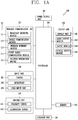
- FIG. 1A is a block diagram of a mobile terminal in accordance with the present disclosure
- FIGS. 1B and 1C are conceptual views of one example of the mobile terminal, viewed from different directions.
- the mobile terminal 100 may include components, such as a wireless communication unit 110, an input unit 120, a sensing unit 140, an output unit 150, an interface unit 160, a memory 170, a controller 180, a power supply unit 190 and the like.
- FIG. 1A illustrates the mobile terminal having various components, but implementing all of the illustrated components is not a requirement. Greater or fewer components may alternatively be implemented.
- the wireless communication unit 110 of those components may typically include one or more modules which permit wireless communications between the mobile terminal 100 and a wireless communication system, between the mobile terminal 100 and another mobile terminal 100, or between the mobile terminal 100 and a network within which another mobile terminal 100 (or an external server) is located.
- the wireless communication unit 110 may include at least one of a broadcast receiving module 111, a mobile communication module 112, a wireless Internet module 113, a short-range communication module 114, a location information module 115 and the like.
- the input unit 120 may include a camera 121 for inputting an image signal, a microphone 122 or an audio input module for inputting an audio signal, or a user input unit 123 (for example, a touch key, a push key (or a mechanical key), etc.) for allowing a user to input information. Audio data or image data collected by the input unit 120 can be analyzed and processed by a user's control command.
- the sensing unit 140 may include at least one sensor which senses at least one of internal information of the mobile terminal, a surrounding environment of the mobile terminal and user information.
- the sensing unit 140 may include a proximity sensor 141, an illumination sensor 142, a touch sensor, an acceleration sensor, a magnetic sensor, a G-sensor, a gyroscope sensor, a motion sensor, an RGB sensor, an infrared (IR) sensor, a finger scan sensor, a ultrasonic sensor, an optical sensor (for example, refer to the camera 121), a microphone 122, a battery gage, an environment sensor (for example, a barometer, a hygrometer, a thermometer, a radiation detection sensor, a thermal sensor, a gas sensor, etc.), and a chemical sensor (for example, an electronic nose, a health care sensor, a biometric sensor, etc.).
- the mobile terminal disclosed herein may utilize information in such a manner of combining information sensed by at least two sensors of those sensors.
- the output unit 150 can output an audio signal, a video signal or a tactile signal.
- the output unit 150 may include a display unit 151, an audio output module 152, a haptic module 153, an optical output module 154 and the like.
- the display unit 151 can have an inter-layered structure or an integrated structure with a touch sensor so as to implement a touch screen.
- the touch screen may provide an output interface between the mobile terminal 100 and a user, as well as functioning as the user input unit 123 which provides an input interface between the mobile terminal 100 and the user.
- the interface unit 160 serves as an interface with various types of external devices connected with the mobile terminal 100.
- the interface unit 160 may include wired or wireless headset ports, external power supply ports, wired or wireless data ports, memory card ports, ports for connecting a device having an identification module, audio input/output (I/O) ports, video I/O ports, earphone ports, or the like.
- the mobile terminal 100 may execute an appropriate control associated with a connected external device, in response to the external device being connected to the interface unit 160.
- the memory 170 can store a plurality of application programs (or applications) executed in the mobile terminal 100, data for operations of the mobile terminal 100, instruction words, and the like. At least some of those application programs can be downloaded from an external server via wireless communication. Some others of those application programs can be installed within the mobile terminal 100 at the time of being shipped for basic functions of the mobile terminal 100 (for example, receiving a call, placing a call, receiving a message, sending a message, etc.). Further, the application programs can be stored in the memory 170, installed in the mobile terminal 100, and executed by the controller 180 to perform an operation (or a function) of the mobile terminal 100.
- the controller 180 can typically control an overall operation of the mobile terminal 100 in addition to the operations associated with the application programs.
- the controller 180 can provide or process information or functions appropriate for a user by processing signals, data, information and the like, which are input or output by the aforementioned components, or activating the application programs stored in the memory 170.
- the controller 180 can control at least part of the components illustrated in FIG. 1A , in order to drive the application programs stored in the memory 170. In addition, the controller 180 can drive the application programs by combining at least two of the components included in the mobile terminal 100 for operation.
- the power supply unit 190 may receive external power or internal power and supply appropriate power required for operating respective elements and components included in the mobile terminal 100 under the control of the controller 180.
- the power supply unit 190 may include a battery, and the battery can be an embedded battery or a replaceable battery.
- At least part of those elements and components can be combined to implement operation and control of the mobile terminal or a control method of the mobile terminal according to various exemplary embodiments described herein. Also, the operation and control or the control method of the mobile terminal can be implemented in the mobile terminal in such a manner of activating at least one application program stored in the memory 170.
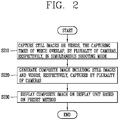
- FIG. 2 is a flow chart illustrating a control method of a mobile terminal according to the present disclosure. Referring to FIG. 2 , the process (S210) of capturing a still image and a video, respectively, the capturing times of which overlap with each other, by a plurality of cameras in a preset simultaneous shooting mode is performed.
- the simultaneous shooting mode can be defined as a mode in which images or videos are captured by a plurality of cameras in a partially or entirely overlapping manner in the capturing times thereof. For example, video capturing by the rear camera 121b can be started while at the same time capturing a still image by the front camera 121a.
- a composite image can be defined as an image in which a plurality of still images or videos, the capturing times of which partially or entirely overlap, can be consecutively displayed.
- the composite image can have a file format including a plurality of images.
- the composite image can have a format in which a plurality of images captured in an overlapping manner in the capturing times are consecutively displayed.
- a plurality of images can be consecutively connected based on whether image capturing time points overlap or not.
- a video captured by the rear camera 121b can be displayed.
- the composite images can be stored and displayed in a separate folder within a photo album.
- the composite images can be stored and displayed in a temporary storage folder until the completion of capturing.
- a still image included in the composite image can be first displayed. Then, when a drag input or the like is applied, a video included in the composite image can be played back.
- the step S220 may include generating a composite image including a still image captured by at least one of the plurality of cameras and a video captured by at least another camera based on the application of a preset user input in the simultaneous shooting mode.
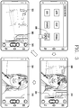
- FIG. 3 is a conceptual view illustrating an embodiment in which a preview image is displayed in a flip photo mode.
- a touch input is applied to an icon 300 corresponding to a simultaneous shooting mode (flip photo mode) in a camera environment setting mode
- the mobile terminal enters a flip photo mode.
- a preview image 330 in which a first preview image 310 by a first camera overlaps with a second preview image 320 by a second camera can be displayed for a predetermined period of time.
- the preview image 310 by the front camera 121a and the preview image 320 by the rear camera 121b can be displayed in an overlapping manner for a short period of time.
- a transparency setting bar 340 for displaying or being set to the transparency of a preview image can be displayed.
- a gauge value 350 of 50% can be displayed on the transparency setting bar 340 while displaying the overlapping preview image 330.
- the overlapping preview image 330 is displayed for a predetermined period of time, only a preview image by a camera set to an initial value (default value) can be displayed.
- a gauge value (0%) is not displayed on the transparency setting bar 340.
- a gauge value 360 of 100% may not be displayed on the transparency setting bar 340.
- a preview image 330 by the front camera 121a and rear camera 121b can be displayed in an overlapping manner. Then, only a preview image (310 or 320) by the front camera 121a or rear camera 121b can be displayed, and the transparency setting bar 340 indicating the transparency of a preview image being displayed can be displayed at the same time.
- FIG. 4 is a conceptual view illustrating an embodiment in which a composite image is generated in a flip photo mode.
- a gauge value (0%) is not displayed on the transparency setting bar 340.
- the front camera 121a and rear camera 121b capture images respectively at the same time.
- the front camera 121a and rear camera 121b can capture the images 310, 320 which are seen as previews, respectively, at the same time.
- an animation effect or the like 420 in which the image 310 captured by the front camera 121a and the image 320 captured by the rear camera 121b are three-dimensionally viewed in an overlapping manner can be displayed. Then, one composite image including images captured by the front camera 121a and rear camera 121b, respectively, can be generated. In one embodiment, while generating a composite image, a message popup window 430 indicating this can be displayed.
- the controller 180 can display a plurality of preview images by the plurality of cameras in an overlapping manner on the display unit 151. Furthermore, the controller 180 can display an object for setting the transparency of the plurality of preview images on the display unit 151.
- FIGS. 5 through 7 are conceptual views illustrating another embodiment in which a preview image is displayed in a flip photo mode.
- a gauge value (0%) is not displayed on the transparency setting bar 340.
- the first preview image 310 by the front camera 121a and the second preview image 320 by the rear camera 121b can be adjusted at the same time.
- the first preview image 310 by the front camera 121a and the second preview image 320 by the rear camera 121b can be displayed in an overlapping manner. Furthermore, a gauge value 510 of 50% can be displayed on the transparency setting bar 340.
- the transparency of the first preview image 310 by the front camera 121a being displayed can increase, and the transparency of the second preview image 320 by the rear camera 121b can decrease.
- the first preview image 310 can be dimly displayed and the second preview image 320 can be clearly displayed, and thus two images 310, 320 can be displayed in an overlapping manner.
- the first preview image 310 by the front camera 121a and the second preview image 320 by the rear camera 121b can be displayed in an overlapping manner. Furthermore, a gauge value 510 of 50% can be displayed on the transparency setting bar 340.
- the transparency of the first preview image 310 by the front camera 121a being displayed can increase, and the transparency of the second preview image 320 by the rear camera 121b can decrease.
- the first preview image 310 can gradually disappear and only the second preview image 320 can be displayed.
- a touch input when a touch input is applied to an uppermost point of the transparency setting bar 340, only the second preview image 320 by the rear camera 121b can be displayed. Furthermore, a gauge value 520 of 100% can be displayed on the transparency setting bar 340.
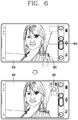
- the controller 180 can display a plurality of preview images by the plurality of cameras, respectively, in one region of the display unit 151. Furthermore, the controller 180 can change locations displayed with the plurality of preview images based on the application of a preset user input.
- the first preview image 310 by the front camera 121a and the second preview image 320 by the rear camera 121b can be respectively displayed in one region of the screen 151.
- the first preview image 310 can be displayed on the entire screen display unit 151, and a thumbnail of the second preview image 320 can be displayed in a small size on the first preview image 310.
- the thumbnail can move to a location to which the drag input is applied.
- the first preview image 310 can be displayed on the entire screen display unit 151, and a thumbnail of the second preview image 320 can be displayed in a small size on the first preview image 310. Subsequently, when a pinch-out input 710 is applied to the thumbnail of the second preview image 320, a size of the thumbnail can increase in proportion to the extent to which the pinch-out input is applied.
- the locations of the preview images 310, 320 being displayed can be changed.
- the second preview image 320 can be displayed on the entire screen, and the thumbnail of the first preview image 310 can be displayed in a small size on the second preview image 320.
- the thumbnail of the second preview image 320 can be increased.
- the locations of the displayed preview images 310, 320 can be changed.
- the controller 180 can also display a plurality of still images or videos corresponding to a plurality of composite images, respectively, generated in the simultaneous shooting mode based on the application of a preset user input. Furthermore, the controller 180 can generate a new composite image including an image selected among the plurality of still images and videos based on the application of a preset user input.
- FIGS. 8 through 11 are conceptual views illustrating an embodiment in which composite images are displayed and edited.
- a touch input is applied to a thumbnail icon or photo album (gallery) icon 820 corresponding to a captured image subsequent to capturing in a flip photo mode, a screen for showing a recently generated composite image can be displayed.
- thumbnail icon or photo album (gallery) icon 820 corresponding to a captured image subsequent to capturing in a flip photo mode
- composite images generated in a flip photo mode can be stored in a separate folder within a photo album. Accordingly, when a touch input is applied to the photo album icon 820, a folder including composite images generated in a flip photo mode can be displayed. Here, if a separate folder does not exist, it can be automatically generated. Alternatively, an indicator (refer to FIG. 17 ) indicating a composite image on a thumbnail of an image within the photo album can be displayed.
- composite images generated in a flip photo mode can be stored in a temporary storage unit until the completion of capturing (or for a predetermined period of time). Accordingly, when a touch input is applied to the thumbnail image 810 corresponding to a captured image, a folder 800 (quick view) in a temporary storage unit can be displayed.
- Composite images can be displayed on the folder 800 in such a temporary storage unit according to a recently generated order.
- still images or videos (1234) captured by the front camera 121a are displayed at the upper side
- still images or videos (abcd) captured by the rear camera 121b can be displayed at the lower side.
- still images or videos being displayed at the upper and lower sides images can be paired with each other.
- composite images can be defined (configured) with images (still images or videos) being paired.
- a most recently generated first composite image may include a first image (1) and an a-image (a).
- the first image (CD) can be captured by the front camera 121a most recently, and the a-image (a) can be captured by the rear camera 121b to overlap with the capturing time of the first image (1).
- the first image (1) can be displayed at an upper left end, and the a-image (a) can be displayed at a lower left end.
- the a-image (a) can be displayed directly under the first image (1) to indicate images being paired with each other.
- a line connected between the first image (1) and the a-image (a) can be displayed.
- a second composite image generated immediately prior to generating the first composite image may include a second image (2) and a b-image (b).
- the second image (2) can be captured by the front camera 121a immediately prior to generating the first composite image
- the b-image (b) can be captured by the rear camera 121b to overlap with the capturing time of the second image (2).
- the second image (2) can be displayed at the right side of the first image (1), and the b-image (b) can be displayed at the right side of the a-image (a).
- the b-image (b) can be displayed directly under the second image (2) to indicate images being paired with each other.
- a line connected between the second image (2) and the b-image (b) can be displayed.
- a drag input can be applied to delete a composite image being temporarily stored. Specifically, when a drag input from the first image (1) to the a-image (a) is applied, the first image (1) and a-image (a) can be deleted from the temporary storage folder 800. In other words, the first composite image (1-a) can be deleted.
- the folder 800 (quick view) in a temporary storage unit can be displayed as illustrated in FIG. 8 .
- still images or videos (1234) captured by the front camera 121a are displayed at the upper side
- still images or videos (abcd) captured by the rear camera 121b can be displayed at the lower side.
- still images or videos being displayed at the upper and lower sides images (still images or videos), the capturing times of which overlap, can be paired with each other.
- the first composite image (1-a) and second composite image (2-b) can be edited.
- a new composite image (2-a) including the second image (2) and a-image (a) can be generated. Accordingly, the first composite image (1-a) and second composite image (2-b) can be deleted, and the first image (1) and b-image (b) may remain as one image, respectively (I).
- a composite image (2-a) including the second image (2) and a-image (a) and a composite image (1-b) including the first image (1) and b-image (b) can be newly generated.
- pairs of images forming the first composite image (1-a) and second composite image (2-b) can be exchanged (II).
- each image can be deleted from the folder 800 in the temporary storage unit.
- a touch input can be applied to the edit icon 910 when that the folder 800 in the temporary storage unit is being displayed, and then a drag input 1000 by two fingers can be applied from a third composite image (3-c) to the first composite image (1-a).
- a new composite image including the third composite image (3- ⁇ ) and first composite image (1-a) can be generated.
- the first image (1) and third image (3) captured by the front camera 121a can be displayed at the upper side, and the a-image (a) and c-image (c) can be displayed at the lower side while being paired. Then, when a touch input is applied to the save icon 930, an edit result can be stored.
- Such an edit result can be checked through the playback of a composite image.
- the first image (1) can be played back and then the third image (3) can be subsequently played back.
- the a-image (a) can be played back and then the c-image (c) can be played back.
- the order of displaying images can be changed according to the direction to which a drag input is applied. Specifically, when a drag input by two fingers is applied from the first composite image (1-a) to the third composite image (3- ⁇ ), during the playback of the composite image (13-ac), as an image captured by the front camera 121a, the third image (3) can be played back and then the first image (1) can be played back. Similarly, as an image captured by the rear camera 121b, the c-image (c) can be played back and then the a-image (a) can be played back.
- a touch input can be applied to the edit icon 910 when the folder 800 in the temporary storage unit is being displayed, and then a still image or video desired to be included in a new composite image can be selected.
- a new composite image (12-3) including the first image (1), second image (2) and third image (3) can be generated.
- a composite image (1-4) including the first image (1) and fourth image (4), a composite image (5-3) including the fifth image (5) and third image (3), and a composite image (2-6) including the second image (2) and sixth image (6) can be deleted.
- a composite image (12-3) including the first image (1) and second image (2) as an image captured by the front camera 121a, and including the third image (3) as an image captured by the rear camera 121b can be generated.
- the fourth image (4), fifth image (5) and sixth image (6) that have been included in the deleted composite image may respectively remain as one image. Then, when a touch input is applied to the save icon 930, an edit result can be stored.
- controller 180 can control a still image to be captured by at least one of the plurality of cameras, and a video to be captured by at least another camera corresponding to a preset condition based on the application of a preset user input in the simultaneous shooting mode.
- FIGS. 12 through 14 are conceptual views illustrating an embodiment in which a still image and a video are captured in a flip photo mode. Specifically, when a video is captured along with a still image in a flip photo mode, a camera for capturing the video can be selected based on a size of the preview screen ( FIG. 13 ), a preview screen (hereinafter, the detailed description thereof will be described) being currently displayed, whether or not a specific condition is sensed ( FIG. 12 ), a user's selection ( FIG. 14 ), and the like.
- a long touch input can be applied to a capture icon when a preview image 1210 by the front camera 121a is being displayed and a situational awareness sensor is activated (ON) in a flip photo mode. Accordingly, a still image can be captured with the front camera 121a, and a video can be captured with the rear camera 121b. In this instance, only a captured image 1210 by the front camera 121a can be viewed or only a video 1220 being captured by the rear camera 121b can be viewed.
- the rear camera 121b can capture a video for a short moment upon sensing a specific situation.
- the specific situation can be sensed based on the movement of the terminal 100, the movement of a subject, other information, and the like.
- a video can be captured to seize a moment at which the movement of a subject is sensed (a moment of extinguishing candles on a cake, a moment at which a batter hits the ball in a baseball field, and the like) or capture a moment of snowing, raining, sunset, sunrise or the like by analyzing the weather or receiving the weather information.
- a situational awareness sensor can be configured with various sensors to sense the situation.
- the situational awareness sensor may include a voice recognition sensor, and a sensor capable of sensing the movement of an object within a subject.
- a video by the rear camera 121b can be captured from a moment at which an image is captured by the front camera 121a. At this time, the rear camera 121b can capture a video only for a short moment.
- a still image can be captured using a camera on which a preview image is currently being displayed, and a video can be captured using a camera on which a preview image is not viewed.
- a still image can be captured using the front camera 121a on which a preview image 1210 is currently being displayed, and a video can be captured using the rear camera 121b.
- a composite image including a still image and a video (video for a short moment) can be generated.
- the controller 180 can set a size of a region being displayed with the plurality of preview images based on the application of a preset user input, and select a plurality of cameras to capture image images or videos among the plurality of cameras.
- the entire screen 151 can be divided into a first region and a second region with the same size. Accordingly, a preview image 1210 by the front camera 121a and a preview image 1220 by the rear camera 121b can be displayed on the divided first and second regions, respectively.
- a size of the divided first and second regions can be adjusted to select a camera on which a video (or still image) is to be captured.
- a video can be captured using a camera for displaying a preview image on a larger region.
- a still image 1310 can be captured using the front camera 121a and a video 1320 can be captured using the rear camera 121b.
- a video 1330 can be captured using the front camera 121a and a still image 1340 can be captured using the rear camera 121b.
- a composite image including a still image and a video (video for a short moment) can be generated.
- the rear camera 121b can be selected as a camera for capturing a video.
- an image 1210 can be captured by the front camera 121a, and a video 1420 can be captured by the rear camera 121b.
- the video 1420 being captured by the rear camera 121b or a thumbnail of the video can be displayed in a small size on a portion of the screen 151.
- a composite image including a still image and a video (video for a short moment) can be generated.
- FIG. 15 is a conceptual view illustrating an embodiment in which a plurality of videos are captured in a flip photo mode.
- a touch input is applied to a video icon 1500 in a flip photo mode
- a video can be captured by the front camera 121a and rear camera 121b, respectively.
- a first video 1501 being captured by the front camera 121a can be displayed on the entire screen 151, and a second video 1502 being captured by the rear camera 121b can be displayed in a small size on a portion of the screen 151.
- a composite image including the first video 1501 and second video 1502 can be generated.
- an icon 1503 corresponding to the first video 1501 can be displayed.
- the first video 1501 can be displayed on the entire screen 151, and each image included in the first video 1501 and second video 1502 can be displayed on the same time line.
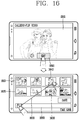
- FIG. 16 is a conceptual view illustrating an embodiment in which a composite image including a plurality of videos is edited.
- a touch input is applied to the icon 1503 in FIG. 15 , a folder in which a composite image is temporarily stored or a folder in which a composite image within a photo album is separately stored can be displayed.
- the first video 1501 can be displayed on the entire screen 151, and an edit icon 1600 can be displayed at an lower end.
- a touch input is applied to the edit icon 1600, a time line 1660 for generating a new video, images included in the first video 1501, images 1620 included in the second video 1502 can be displayed according to a time sequence.
- images 1610 included in the first video 1501 captured by the front camera 121a can be displayed at an upper side
- images 1620 included in the second video 1502 captured by the rear camera 121b can be displayed at a lower side.
- the images 1610, 1620 can be respectively displayed according to a captured time sequence. Accordingly, images captured at the same time can be displayed with a pair.
- a first image 1640 and a second image 1650 can be displayed with a pair at the upper and lower sides as images captured at the same time.
- a drag input can be applied to one of the images 1610, 1620 to move them to the time lime 1660 for generating a new video.
- a drag input to the time lime 1660 when a drag input to the time lime 1660 is applied on the first image 1640, a thumbnail of the first image 1640 can be displayed on the time lime 1660.
- a drag input to the time lime 1660 can be applied on other images to select scenes (images) that follow the first image 1640, and a touch input can be applied to the save icon to generate a new video.
- the controller 180 can display at least one still image included in a composite image at preset time intervals based on the application of a preset user input when another still image included in the composite image generated in the simultaneous shooting mode is being displayed.
- a still image being displayed can be switched based on a (force) touch input, an input of tilting the body, an eye tracking, a tactile sensing change, or the like.
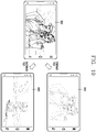
- FIGS. 17 and 18 are conceptual views illustrating an embodiment in which a composite image including a plurality of still images is played back.
- composite images generated in a flip photo mode can be stored in a temporary storage space or a separate folder within a photo album.
- an indicator for indicating a composite image can be displayed on a thumbnail or the thumbnail can be displayed in a preset specific shape.
- an icon having a specific shape can be displayed (F) on a thumbnail of the first composite image within a photo album.
- a thumbnail 1704 of the first composite image within a photo album can be displayed in a shape in which a first still image 1701 and a second still image 1702 included in the first composite image overlap.
- the first still image 1701 can be displayed on the entire screen 151.
- an image 1703 in which the first still image 1701 and second still image 1702 overlap can be displayed for a predetermined period of time.
- the second still image 1702 can be displayed again for a predetermined period of time.
- still images included in a composite image can be sequentially displayed by a touch input.
- the first still image 1701 disappears while displaying the second still image 1702.
- the first still image and second still image can be displayed in an overlapping manner for a predetermined period of time.
- a displayed image can be switched according to a physical distance between the user and the terminal 100. Specifically, a first still image can be displayed when a distance between the user and terminal 100 is close. Subsequently, as the distance between the user and terminal 100 becomes far, the first still image can be gradually dimmed, and the second still image can be clearly displayed (eye tracking).
- a first still image or second still image can be displayed according to an angle or direction of tilting the terminal 100.
- an image can be immediately switched to another image, and gradually switched in an overlapping manner for a predetermined period of time.
- the first still image 1701 included in the first composite image can be displayed on the entire screen 151, and the second still image 1702 captured along with the first still image 1701 at the same time maybe displayed in a separate one region.
- the display locations of the images 1701, 1702 can be changed to each other.
- the second still image 1702 can be displayed on the entire screen 151, and the first still image 1701 can be displayed in a separate one region.
- controller 180 can display only a still image or video based on the application of a preset user input when the still image and the video included in a composite image generated in the simultaneous shooting mode are being displayed in an overlapping manner.
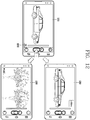
- FIGS. 19 through 21 are conceptual views illustrating an embodiment in which a composite image consisting of a plurality of still images and videos is played back.
- a composite image may include a still image 1910 and a video 1920, and can be displayed with an image 1930 in which initial or major screens (images) of the still image 1910 and video 1920 overlap.
- only an image captured by the front camera 121a or rear camera 121b can be selectively displayed according to a direction of tilting the terminal 100.
- only the still image 1910 captured by the front camera 121a can be displayed on the entire screen 151.
- the controller 180 can play back the video in a forward or reverse direction based on the application of a preset user input when a video included in the composite image is being displayed.
- a playback direction of a video 2010 included in a composite image can be set according to a direction of tilting the terminal 100.
- the video 2010 can be played back (2020) in a forward direction.
- the video 2010 can be played back (2030) in a reverse direction.
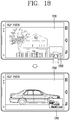
- the controller 180 can display a video included in a composite image based on the application of a preset user input when a still image included in the composite image generated in the simultaneous shooting mode is being displayed.
- the still image 2110 can be displayed on the entire screen 151.
- an indicator 2120 for indicating the existence of the video 2140, the capturing time of which overlaps can be displayed at a lower end of the still image 2110 being displayed. For example, a portion 2120 in which an image seems to be folded can be displayed.
- the controller 180 can play back a still image or video that has captured an object based on the application of a preset user input selecting the object within a still image or video when the still image or video included in a composite image generated in the simultaneous shooting mode is being displayed.
- FIG. 22 is a conceptual view illustrating an embodiment in which only a portion displayed with a specific object on a video is separately played back.
- a focus region 2220, 2230, 2240 for selecting a specific subject can be displayed on a video 2210 captured for a short period of time.
- the focus region 2220, 2230, 2240 can be displayed with a circle, a rectangle or the like to include a face of a figure.
- a portion 2250 in which the first figure is a main subject on the video 2210 can be played back on a separate window. Furthermore, when a touch input is applied to the save icon 2260, the portion 2250 in which the first figure is a main subject on the video 2210 can be stored as a separate video file.
- the video 2210 when a touch input is applied to a background region 2270 other than a figure on the video 2210, the video 2210 can be played back 2280 on the entire screen 151. According to the embodiment of FIG. 22 , only a portion of a specific object on the entire video can be played back or separately stored.
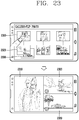
- FIG. 23 is a conceptual view illustrating another embodiment in which a composite image including a plurality of still images and videos is played back.
- a composite image may include still images or videos captured by a plurality of cameras.
- a first composite image may include a first still image 2310 captured by the front camera 121a, an a-video 2320 captured by a first rear camera, a b-video 2330 captured by a second rear camera.
- the front camera 121a can capture a first still image 2310.
- the first rear camera and second rear camera can capture the a-video 2320 and b-video 2330, respectively.
- the videos 2320, 2330 can be captured along with the first still image 2310 at the same time or captured when a specific condition such as the movement of a subject is sensed. Then, a first composite image including the first image 2310, a-video 2320 and b-video 2330 can be generated.
- the first composite image can be stored in a separate temporary storage folder or stored in a separate folder within a gallery.
- the first still image 2310 captured by the front camera 121a can be displayed at an upper side, and the a-video 2320 and b-video 2330 captured by the first and the second rear camera, respectively, can be displayed at a lower side while being paired. At this time, a line for connecting images with a pair can be displayed.
- the first composite image can be displayed.
- the first still image 2310, a-video 2320 and b-video 2330 can be displayed on each of the divided screens 151.
- each image can be played back at the same time.
- individual images included in the composite image can be shared or the entire composite image can be shared.
- a composite image and individual images included in the composite image can be respectively stored, and the composite image can be changed to an individual image.
- the first image can be deleted from the first and the second image included in the composite image. As a result, only the second image remains.
- controller 180 can control still images to be consecutively captured by one of the plurality of cameras based on the application of a preset user input in the simultaneous shooting mode, and generate a composite image in which the same objects within the consecutively captured still images are combined to be displayed at the same time.
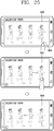
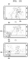
- FIGS. 24 and 25 are conceptual views illustrating an embodiment associated with the playback of consecutively captured still images.
- a specific shooting technique is selected in a flip photo mode, a plurality of images 2410, 2420, 2430, 2440 can be captured at short time intervals.
- one composite image 2400 in which a subject is combined with a background image can be generated.
- the composite image 2400 can be stored in a separate folder within a photo album.
- another composite image including the composite image 2400 can be generated.
- a composite image including the composite image 2400 and the plurality of images 2410, 2420, 2430, 2440 captured at short time intervals can be generated.
- the controller 180 can display the consecutively captured still images in a capture sequence based on a preset user input applied to the composite image. In another embodiment, the controller 180 can display the consecutively captured still images in a reverse order to the capture sequence based on a preset user input applied to the composite image.
- a plurality of images captured at short time intervals while a touch input 2500 is applied to the composite image 2400 can be sequentially displayed (2510) according to a time sequence.
- a subject at a next time can be displayed when a subject at a previous time has been displayed. Accordingly, the process of moving a subject can be sequentially displayed according to a time sequence.
- a finger touching the composite image 2400 is released, a plurality of images captured at short time intervals can be displayed (2520) in a reverse order to the capture time sequence.
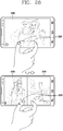
- FIGS. 26 through 28 are conceptual views illustrating an embodiment in which a composite image consisting of a plurality of videos is played back.
- a drag input or swipe input 2620 can be applied while a first video constituting a composite image is played back (2610) on the entire screen.
- a second video which is another video constituting a composite image
- a thumbnail 2650 of the first video being played back on the entire screen can be displayed on the time line.
- the second video being played back (2640) in a separate one region from the first video being played back (2610) on the entire screen can be a video captured at the same time.
- the second video can be played back (2630) on the entire screen, and the first video can be played back (2660) in a separate one region.
- a thumbnail 2670 of the second video being played back on the entire screen can be displayed on the time line.
- a drag input or swipe input 2700 can be applied while the first video constituting a composite image is being played back (2610) on the entire screen. Accordingly, the second video, which is another video constituting a composite image, can be played back (2630) on the entire screen.
- a pinch-in input 2810 can be applied while a first video 2830 constituting a composite image is being played back on the entire screen. Accordingly, the entire screen can be divided into regions, and videos constituting a composite image can be played back in the divided regions, respectively. In other words, a first video 2830 and a second video 2840 constituting a composite image can be played back in the divided regions, respectively. Subsequently, when a pinch-out input 2820 is applied, it may return again to an initial state. In other words, only the first video 2830 can be played back on the entire screen.
- Embodiments of the present disclosure have an advantage of capturing at the same time with multi-camera lenses, and providing an image combination mode according to various visual effects.
- embodiments have an advantage of automatically capturing meaningful photos and videos without editing using a situational awareness sensor.
- the present disclosure has an advantage of more specifically displaying only a portion associated with a specific subject such as a moving object or the like.
- the foregoing present invention can be implemented as codes readable by a computer on a medium written by the program.
- the computer-readable media may include all kinds of recording devices in which data readable by a computer system is stored. Examples of the computer-readable media may include hard disk drive (HDD), solid state disk (SSD), ROM, RAM, CD-ROM, magnetic tape, floppy disk, and optical data storage device, and the like, and also include a device implemented in the form of a carrier wave (for example, transmission via the Internet).
- the computer may include the controller 180 of the terminal. Accordingly, the detailed description thereof should not be construed as restrictive in all aspects but considered as illustrative. The scope of the invention should be determined by reasonable interpretation of the appended claims.
Landscapes
- Engineering & Computer Science (AREA)
- Signal Processing (AREA)
- Multimedia (AREA)
- Human Computer Interaction (AREA)
- Physics & Mathematics (AREA)
- General Physics & Mathematics (AREA)
- Theoretical Computer Science (AREA)
- Computer Networks & Wireless Communication (AREA)
- Telephone Function (AREA)
- Studio Devices (AREA)
Claims (14)
- Mobiles Endgerät (100), das aufweist:einen drahtlosen Kommunikationsprozessor (110), der konfiguriert ist, um drahtlose Kommunikation bereitzustellen;eine Anzeige (151);eine erste Kamera, die konfiguriert ist, um ein Standbild aufzunehmen, und eine zweite Kamera, die konfiguriert ist, um ein Videobild zu überlappenden Aufnahmezeiten in einer vorgegebenen Simultanaufhahmebetriebsart aufzunehmen; undeine Steuerung (180), die konfiguriert ist, um:die Anzeige zu steuern, um ein Vorschaubild (330) anzuzeigen, in dem ein erstes Vorschaubild (310) von der ersten Kamera mit einem zweiten Vorschaubild (320) von der zweiten Kamera überlappt, wenn eine Berührungseingabe auf ein Piktogramm (300) eingegeben wird, das der vorgegebenen Simultanaufnahmebetriebsart entspricht,wobei ein Transparenzfestlegungsbalken (340) zum Festlegen einer Transparenz des Vorschaubilds (330) auf der Anzeige angezeigt wird,wenn eine vorgegebene Berührungseingabe auf den Transparenzfestlegungsbalken (340) angewendet wird, die Transparenz des Vorschaubilds einzustellen, wobei die Transparenz des ersten Vorschaubilds (310) von der ersten Kamera und die Transparenz des zweiten Vorschaubilds (320) von der zweiten Kamera ansprechend auf die vorgegebene Berührungseingabe gleichzeitig eingestellt werden, ansprechend auf eine vorgegebene Benutereingabe, ein zusammengesetztes Bild, welches das von der ersten Kamera aufgenommene Standbild und das von der zweiten Kamera aufgenommene Videobild umfasst, zu erzeugen und das zusammengesetzte Bild auf der Anzeige anzuzeigen.
- Mobiles Endgerät nach Anspruch 1, wobei die Steuerung ferner konfiguriert ist, um nur das zweite Vorschaubild auf der Anzeige anzuzeigen, indem die Transparenz des ersten Vorschaubilds und die Transparenz des zweiten Vorschaubilds gleichzeitig eingestellt werden.
- Mobiles Endgerät nach den Ansprüchen 1 bis 2, wobei die Steuerung ferner konfiguriert ist, um das erste Vorschaubild, das dem Standbild entspricht, als Vollbild und das zweite Vorschaubild, das dem Videobild entspricht, als Miniaturbild auf der Anzeige anzuzeigen, und
Orte der ersten und zweiten Vorschaubilder auf der Anzeige ansprechend auf eine spezifische Benutzereingabe zu ändern. - Mobiles Endgerät nach den Ansprüchen 1 bis 3, wobei die Steuerung ferner konfiguriert ist, um ein erstes erzeugtes zusammengesetztes Bild auf der Anzeige anzuzeigen, indem ein erstes Standbild an einem ersten Anzeigeort auf der Anzeige und ein erstes Videobild auf einem zweiten Ort auf der Anzeige angezeigt werden, und ein zweites erzeugtes zusammengesetztes Bild auf der Anzeige anzuzeigen, indem ein zweites Standbild an einem dritten Anzeigeort und ein zweites Videobild an einem vierten Anzeigeort auf der Anzeige angezeigt werden.
- Mobiles Endgerät nach den Ansprüchen 1 bis 4, wobei die Steuerung ferner konfiguriert ist, um ein drittes zusammengesetztes Bild zu erzeugen, das beliebige zwei oder mehr Ausgewählte des ersten Standbilds, des zweiten Standbilds, des ersten Videobilds und des zweiten Videobilds umfasst.
- Mobiles Endgerät nach den Ansprüchen 1 bis 5, wobei die Steuerung ferner konfiguriert ist, um das Standbild unter Verwendung der ersten Kamera und das Video unter Verwendung der zweiten Kamera ansprechend auf eine vorgegebene Bedingung in der Simultanaufhahmebetriebsart aufzunehmen.
- Mobiles Endgerät nach den Ansprüchen 1 bis 6, wobei die Steuerung ferner konfiguriert ist, um:eine Anzeigegröße eines ersten Bereichs, der mit dem ersten Vorschaubild angezeigt wird, und eine Anzeigegröße eines zweiten Bereichs, der mit dem zweiten Vorschaubild angezeigt wird, ansprechend auf eine spezifische Benutzereingabe festzulegen, undansprechend auf die spezifische Benutzereingabe, welche die Anzeigegröße des zweiten Bereichs größer als die Anzeigegröße des ersten Bereichs vergrößert, die zweite Kamera zum Aufnehmen des Videobilds auszuwählen.
- Mobiles Endgerät nach den Ansprüchen 1 bis 7, wobei die Steuerung ferner konfiguriert ist, um ansprechend auf eine spezifische Benutzereingabe in vorgegebenen Zeitabständen Standbilder in dem zusammengesetzten Bild anzuzeigen.
- Mobiles Endgerät nach den Ansprüchen 1 bis 8, wobei die Steuerung ferner konfiguriert ist, um ansprechend auf eine spezifische Benutzereingabe, wenn das zusammengesetzte Bild angezeigt wird, nur das Standbild oder das Videobild anzuzeigen.
- Mobiles Endgerät nach den Ansprüchen 1 bis 9, wobei die Steuerung ferner konfiguriert ist, um ansprechend auf eine spezifische Benutzereingabe, wenn das in dem zusammengesetzten Bild enthaltene Standbild in der Simultanaufnahmebetriebsart angezeigt wird, das in dem zusammengesetzten Bild enthaltene Videobild anzuzeigen, und um ansprechend auf eine vorgegebene Benutzereingabe, wenn das in dem zusammengesetzten Bild enthaltene Videobild angezeigt wird, das Videobild in einer Vorwärts- oder Rückwärtsrichtung abzuspielen.
- Mobiles Endgerät nach den Ansprüchen 1 bis 10, wobei die Steuerung ferner konfiguriert ist, um, wenn das Videobild mehrere Objekte enthält, das Standbild anzuzeigen oder ein Videobild abzuspielen, das ein benutzerausgewähltes Objekt von den mehren Objekten umfasst.
- Mobiles Endgerät nach den Ansprüchen 1 bis 11, wobei die Steuerung ferner konfiguriert ist, um:ansprechend auf eine spezifische Benutzereingabe in der Simultanaufnahmebetriebsart fortlaufend mehrere Standbilder durch die erste Kamera aufzunehmen,ein anderes zusammengesetztes Bild zu erzeugen, das die fortlaufend aufgenommenen Standbilder enthält, unddas andere zusammengesetzte Bild auf der Anzeige anzuzeigen.
- Mobiles Endgerät nach den Ansprüchen 1 bis 12, wobei die Steuerung ferner konfiguriert ist, um die fortlaufend aufgenommenen Standbilder basierend auf einer vorgegebenen Benutzereingabe, die auf das zusammengesetzte Bild angewendet wird, in einer Aufnahmesequenz anzuzeigen, und
die fortlaufend aufgenommenen Standbilder basierend auf einer anderen Benutzereingabe, die auf das zusammengesetzte Bild angewendet wird, in einer zu der Aufnahmesequenz umgekehrten Reihenfolge anzuzeigen. - Verfahren zur Steuerung eines mobilen Endgeräts (100), wobei das Verfahren aufweist:Aufnehmen eines Standbilds über eine erste Kamera des mobilen Endgeräts und Aufnehmen eines Videobilds zu überlappenden Aufnahmezeiten über eine zweite Kamera des mobilen Endgeräts in einer vorgegebenen Simultanaufnahmebetriebsart;Steuern einer Anzeige über eine Steuerung (180) des mobilen Endgeräts, um ein Vorschaubild (330) anzuzeigen, in dem ein erstes Vorschaubild (310) von der ersten Kamera mit einem zweiten Vorschaubild (320) von der zweiten Kamera überlappt, wenn eine Berührungseingabe auf ein Piktogramm (300) eingegeben wird, das der vorgegebenen Simultanaufhahmebetriebsart entspricht,wobei ein Transparenzfestlegungsbalken (340) zum Festlegen einer Transparenz des Vorschaubilds (330) auf der Anzeige angezeigt wird,wenn eine vorgegebene Berührungseingabe auf den Transparenzfestlegungsbalken (340) angewendet wird, die Transparenz des Vorschaubilds einzustellen, wobei die Transparenz des ersten Vorschaubilds (310) von der ersten Kamera und die Transparenz des zweiten Vorschaubilds (320) von der zweiten Kamera ansprechend auf die vorgegebene Berührungseingabe gleichzeitig eingestellt werden,ansprechend auf eine vorgegebene Benutzereingabe über die Steuerung (180) des mobilen Endgeräts ein zusammengesetztes Bild, welches das von der ersten Kamera aufgenommene Standbild und das von der zweiten Kamera aufgenommene Videobild umfasst, zu erzeugen; unddas zusammengesetzte Bild auf der Anzeige (151) des mobilen Endgeräts anzuzeigen.
Applications Claiming Priority (1)
| Application Number | Priority Date | Filing Date | Title |
|---|---|---|---|
| KR1020160039588A KR20170112492A (ko) | 2016-03-31 | 2016-03-31 | 이동 단말기 및 그 제어방법 |
Publications (2)
| Publication Number | Publication Date |
|---|---|
| EP3226537A1 EP3226537A1 (de) | 2017-10-04 |
| EP3226537B1 true EP3226537B1 (de) | 2019-09-25 |
Family
ID=57539103
Family Applications (1)
| Application Number | Title | Priority Date | Filing Date |
|---|---|---|---|
| EP16202999.5A Active EP3226537B1 (de) | 2016-03-31 | 2016-12-08 | Mobiles endgerät und verfahren zur steuerung davon |
Country Status (3)
| Country | Link |
|---|---|
| US (1) | US10104312B2 (de) |
| EP (1) | EP3226537B1 (de) |
| KR (1) | KR20170112492A (de) |
Cited By (1)
| Publication number | Priority date | Publication date | Assignee | Title |
|---|---|---|---|---|
| CN110149479A (zh) * | 2019-05-20 | 2019-08-20 | 上海闻泰信息技术有限公司 | 双摄像头成像方法、装置、终端和介质 |
Families Citing this family (19)
| Publication number | Priority date | Publication date | Assignee | Title |
|---|---|---|---|---|
| EP3182692B1 (de) * | 2014-08-12 | 2023-12-20 | Sony Group Corporation | Informationsverarbeitungsvorrichtung, programm und informationsverarbeitungsverfahren |
| GB2531758A (en) * | 2014-10-29 | 2016-05-04 | Nokia Technologies Oy | Method and apparatus for determining the capture mode following capture of the content |
| US10194078B2 (en) * | 2017-06-09 | 2019-01-29 | Immersion Corporation | Haptic enabled device with multi-image capturing abilities |
| US10855730B2 (en) * | 2017-10-31 | 2020-12-01 | Crestron Electronics, Inc. | Clean video switch among multiple video feeds in a security system |
| CN108234891B (zh) * | 2018-04-04 | 2019-11-05 | 维沃移动通信有限公司 | 一种拍照方法及移动终端 |
| CN113170038B (zh) * | 2018-11-29 | 2023-06-13 | 富士胶片株式会社 | 抖动校正控制装置、抖动校正控制装置的工作方法、存储介质及摄像装置 |
| EP3873084B1 (de) * | 2018-12-06 | 2023-10-04 | Huawei Technologies Co., Ltd. | Verfahren zum fotografieren eines bildes mit langer belichtung und elektronische vorrichtung |
| CN110010061A (zh) * | 2019-03-27 | 2019-07-12 | 武汉华星光电半导体显示技术有限公司 | 显示装置及其制造方法 |
| CN110784674B (zh) | 2019-10-30 | 2022-03-15 | 北京字节跳动网络技术有限公司 | 视频处理的方法、装置、终端及存储介质 |
| US11997409B2 (en) | 2019-10-30 | 2024-05-28 | Beijing Bytedance Network Technology Co., Ltd. | Video processing method and apparatus, and terminal and storage medium |
| CN113573124B (zh) * | 2020-04-29 | 2023-05-09 | 海信视像科技股份有限公司 | 显示设备及摄像头检测方法 |
| WO2022226745A1 (zh) * | 2021-04-26 | 2022-11-03 | 深圳市大疆创新科技有限公司 | 拍摄方法、控制装置、拍摄设备及存储介质 |
| KR102514852B1 (ko) * | 2021-05-18 | 2023-03-29 | 주식회사 쓰리아이 | 단말기 거치대와 연동하는 휴대 단말기 및 그를 이용한 화상 합성 방법 |
| CN115473996B (zh) * | 2021-06-11 | 2024-04-05 | 荣耀终端有限公司 | 一种视频拍摄方法及电子设备 |
| CN114143462A (zh) * | 2021-11-30 | 2022-03-04 | 维沃移动通信有限公司 | 拍摄方法及装置 |
| CN116112787B (zh) * | 2022-07-05 | 2023-10-20 | 荣耀终端有限公司 | 拍照时显示缩略图的方法和电子设备 |
| CN114845059B (zh) * | 2022-07-06 | 2022-11-18 | 荣耀终端有限公司 | 一种拍摄方法及相关设备 |
| CN117425057A (zh) | 2022-07-07 | 2024-01-19 | 抖音视界(北京)有限公司 | 用于影像拍摄的方法、装置、设备和存储介质 |
| CN115334246A (zh) * | 2022-09-06 | 2022-11-11 | 抖音视界有限公司 | 用于影像拍摄的方法、装置、设备和存储介质 |
Family Cites Families (7)
| Publication number | Priority date | Publication date | Assignee | Title |
|---|---|---|---|---|
| KR101709935B1 (ko) | 2009-06-23 | 2017-02-24 | 삼성전자주식회사 | 영상촬영장치 및 그 제어방법 |
| KR101739379B1 (ko) | 2011-01-11 | 2017-05-24 | 삼성전자주식회사 | 디지털 촬영 장치 및 이의 제어 방법 |
| US8988558B2 (en) * | 2011-04-26 | 2015-03-24 | Omnivision Technologies, Inc. | Image overlay in a mobile device |
| US20130083151A1 (en) * | 2011-09-30 | 2013-04-04 | Lg Electronics Inc. | Electronic device and method for controlling electronic device |
| JP5884421B2 (ja) | 2011-11-14 | 2016-03-15 | ソニー株式会社 | 画像処理装置、画像処理装置の制御方法およびプログラム |
| US8866943B2 (en) | 2012-03-09 | 2014-10-21 | Apple Inc. | Video camera providing a composite video sequence |
| KR102153435B1 (ko) | 2013-12-20 | 2020-09-08 | 엘지전자 주식회사 | 이동 단말기 및 이의 제어방법 |
-
2016
- 2016-03-31 KR KR1020160039588A patent/KR20170112492A/ko not_active Application Discontinuation
- 2016-10-03 US US15/283,586 patent/US10104312B2/en active Active
- 2016-12-08 EP EP16202999.5A patent/EP3226537B1/de active Active
Non-Patent Citations (1)
| Title |
|---|
| None * |
Cited By (1)
| Publication number | Priority date | Publication date | Assignee | Title |
|---|---|---|---|---|
| CN110149479A (zh) * | 2019-05-20 | 2019-08-20 | 上海闻泰信息技术有限公司 | 双摄像头成像方法、装置、终端和介质 |
Also Published As
| Publication number | Publication date |
|---|---|
| EP3226537A1 (de) | 2017-10-04 |
| US10104312B2 (en) | 2018-10-16 |
| US20170289462A1 (en) | 2017-10-05 |
| KR20170112492A (ko) | 2017-10-12 |
Similar Documents
| Publication | Publication Date | Title |
|---|---|---|
| EP3226537B1 (de) | Mobiles endgerät und verfahren zur steuerung davon | |
| US11816303B2 (en) | Device, method, and graphical user interface for navigating media content | |
| US10848661B2 (en) | Devices, methods, and graphical user interfaces for capturing and recording media in multiple modes | |
| US10686990B2 (en) | Mobile terminal and method of controlling the same | |
| EP3125524A1 (de) | Tragbares endgerät und verfahren zur steuerung davon | |
| EP3136705B1 (de) | Tragbares endgerät und verfahren zur steuerung davon | |
| US9185286B2 (en) | Combining effective images in electronic device having a plurality of cameras | |
| JP4811452B2 (ja) | 画像処理装置、画像表示方法および画像表示プログラム | |
| JP2022549236A (ja) | 機械翻訳方法および電子デバイス | |
| EP3147906A1 (de) | Mobiles endgerät und verfahren zur steuerung davon | |
| US20160165133A1 (en) | Method of controlling camera of device and device thereof | |
| EP3154255B1 (de) | Bildgebungsvorrichtung und videoerzeugungsverfahren | |
| CN110069181B (zh) | 跨文件夹的文件处理方法、装置、设备及存储介质 | |
| KR20180133743A (ko) | 이동 단말기 및 그 제어 방법 | |
| EP3226544A1 (de) | Mobiles endgerät und verfahren zur steuerung davon | |
| JP2014123378A (ja) | 文字拡大表示方法 | |
| KR20180131908A (ko) | 이동 단말기 및 그것의 동작방법 | |
| CN111381750B (zh) | 电子装置及其控制方法和计算机可读存储介质 | |
| KR20160022550A (ko) | 이동 단말기 | |
| US20240045572A1 (en) | Device, method, and graphical user interface for navigating media content | |
| US20230254555A1 (en) | Electronic apparatus, control method therefor, and computer-readable storage medium storing program | |
| WO2023160143A1 (zh) | 浏览多媒体内容的方法及装置 | |
| KR20200079209A (ko) | 이동 단말기 및 그 제어 방법 |
Legal Events
| Date | Code | Title | Description |
|---|---|---|---|
| PUAI | Public reference made under article 153(3) epc to a published international application that has entered the european phase |
Free format text: ORIGINAL CODE: 0009012 |
|
| STAA | Information on the status of an ep patent application or granted ep patent |
Free format text: STATUS: REQUEST FOR EXAMINATION WAS MADE |
|
| 17P | Request for examination filed |
Effective date: 20161208 |
|
| AK | Designated contracting states |
Kind code of ref document: A1 Designated state(s): AL AT BE BG CH CY CZ DE DK EE ES FI FR GB GR HR HU IE IS IT LI LT LU LV MC MK MT NL NO PL PT RO RS SE SI SK SM TR |
|
| AX | Request for extension of the european patent |
Extension state: BA ME |
|
| STAA | Information on the status of an ep patent application or granted ep patent |
Free format text: STATUS: EXAMINATION IS IN PROGRESS |
|
| 17Q | First examination report despatched |
Effective date: 20180814 |
|
| GRAP | Despatch of communication of intention to grant a patent |
Free format text: ORIGINAL CODE: EPIDOSNIGR1 |
|
| STAA | Information on the status of an ep patent application or granted ep patent |
Free format text: STATUS: GRANT OF PATENT IS INTENDED |
|
| INTG | Intention to grant announced |
Effective date: 20190412 |
|
| GRAS | Grant fee paid |
Free format text: ORIGINAL CODE: EPIDOSNIGR3 |
|
| GRAA | (expected) grant |
Free format text: ORIGINAL CODE: 0009210 |
|
| STAA | Information on the status of an ep patent application or granted ep patent |
Free format text: STATUS: THE PATENT HAS BEEN GRANTED |
|
| AK | Designated contracting states |
Kind code of ref document: B1 Designated state(s): AL AT BE BG CH CY CZ DE DK EE ES FI FR GB GR HR HU IE IS IT LI LT LU LV MC MK MT NL NO PL PT RO RS SE SI SK SM TR |
|
| REG | Reference to a national code |
Ref country code: GB Ref legal event code: FG4D |
|
| REG | Reference to a national code |
Ref country code: CH Ref legal event code: EP |
|
| REG | Reference to a national code |
Ref country code: AT Ref legal event code: REF Ref document number: 1184968 Country of ref document: AT Kind code of ref document: T Effective date: 20191015 |
|
| REG | Reference to a national code |
Ref country code: IE Ref legal event code: FG4D |
|
| REG | Reference to a national code |
Ref country code: DE Ref legal event code: R096 Ref document number: 602016021173 Country of ref document: DE |
|
| REG | Reference to a national code |
Ref country code: NL Ref legal event code: MP Effective date: 20190925 |
|
| PG25 | Lapsed in a contracting state [announced via postgrant information from national office to epo] |
Ref country code: NO Free format text: LAPSE BECAUSE OF FAILURE TO SUBMIT A TRANSLATION OF THE DESCRIPTION OR TO PAY THE FEE WITHIN THE PRESCRIBED TIME-LIMIT Effective date: 20191225 Ref country code: SE Free format text: LAPSE BECAUSE OF FAILURE TO SUBMIT A TRANSLATION OF THE DESCRIPTION OR TO PAY THE FEE WITHIN THE PRESCRIBED TIME-LIMIT Effective date: 20190925 Ref country code: HR Free format text: LAPSE BECAUSE OF FAILURE TO SUBMIT A TRANSLATION OF THE DESCRIPTION OR TO PAY THE FEE WITHIN THE PRESCRIBED TIME-LIMIT Effective date: 20190925 Ref country code: LT Free format text: LAPSE BECAUSE OF FAILURE TO SUBMIT A TRANSLATION OF THE DESCRIPTION OR TO PAY THE FEE WITHIN THE PRESCRIBED TIME-LIMIT Effective date: 20190925 Ref country code: FI Free format text: LAPSE BECAUSE OF FAILURE TO SUBMIT A TRANSLATION OF THE DESCRIPTION OR TO PAY THE FEE WITHIN THE PRESCRIBED TIME-LIMIT Effective date: 20190925 Ref country code: BG Free format text: LAPSE BECAUSE OF FAILURE TO SUBMIT A TRANSLATION OF THE DESCRIPTION OR TO PAY THE FEE WITHIN THE PRESCRIBED TIME-LIMIT Effective date: 20191225 |
|
| REG | Reference to a national code |
Ref country code: LT Ref legal event code: MG4D |
|
| PG25 | Lapsed in a contracting state [announced via postgrant information from national office to epo] |
Ref country code: LV Free format text: LAPSE BECAUSE OF FAILURE TO SUBMIT A TRANSLATION OF THE DESCRIPTION OR TO PAY THE FEE WITHIN THE PRESCRIBED TIME-LIMIT Effective date: 20190925 Ref country code: GR Free format text: LAPSE BECAUSE OF FAILURE TO SUBMIT A TRANSLATION OF THE DESCRIPTION OR TO PAY THE FEE WITHIN THE PRESCRIBED TIME-LIMIT Effective date: 20191226 Ref country code: RS Free format text: LAPSE BECAUSE OF FAILURE TO SUBMIT A TRANSLATION OF THE DESCRIPTION OR TO PAY THE FEE WITHIN THE PRESCRIBED TIME-LIMIT Effective date: 20190925 |
|
| REG | Reference to a national code |
Ref country code: AT Ref legal event code: MK05 Ref document number: 1184968 Country of ref document: AT Kind code of ref document: T Effective date: 20190925 |
|
| PG25 | Lapsed in a contracting state [announced via postgrant information from national office to epo] |
Ref country code: IT Free format text: LAPSE BECAUSE OF FAILURE TO SUBMIT A TRANSLATION OF THE DESCRIPTION OR TO PAY THE FEE WITHIN THE PRESCRIBED TIME-LIMIT Effective date: 20190925 Ref country code: ES Free format text: LAPSE BECAUSE OF FAILURE TO SUBMIT A TRANSLATION OF THE DESCRIPTION OR TO PAY THE FEE WITHIN THE PRESCRIBED TIME-LIMIT Effective date: 20190925 Ref country code: RO Free format text: LAPSE BECAUSE OF FAILURE TO SUBMIT A TRANSLATION OF THE DESCRIPTION OR TO PAY THE FEE WITHIN THE PRESCRIBED TIME-LIMIT Effective date: 20190925 Ref country code: PT Free format text: LAPSE BECAUSE OF FAILURE TO SUBMIT A TRANSLATION OF THE DESCRIPTION OR TO PAY THE FEE WITHIN THE PRESCRIBED TIME-LIMIT Effective date: 20200127 Ref country code: NL Free format text: LAPSE BECAUSE OF FAILURE TO SUBMIT A TRANSLATION OF THE DESCRIPTION OR TO PAY THE FEE WITHIN THE PRESCRIBED TIME-LIMIT Effective date: 20190925 Ref country code: PL Free format text: LAPSE BECAUSE OF FAILURE TO SUBMIT A TRANSLATION OF THE DESCRIPTION OR TO PAY THE FEE WITHIN THE PRESCRIBED TIME-LIMIT Effective date: 20190925 Ref country code: EE Free format text: LAPSE BECAUSE OF FAILURE TO SUBMIT A TRANSLATION OF THE DESCRIPTION OR TO PAY THE FEE WITHIN THE PRESCRIBED TIME-LIMIT Effective date: 20190925 Ref country code: AT Free format text: LAPSE BECAUSE OF FAILURE TO SUBMIT A TRANSLATION OF THE DESCRIPTION OR TO PAY THE FEE WITHIN THE PRESCRIBED TIME-LIMIT Effective date: 20190925 Ref country code: AL Free format text: LAPSE BECAUSE OF FAILURE TO SUBMIT A TRANSLATION OF THE DESCRIPTION OR TO PAY THE FEE WITHIN THE PRESCRIBED TIME-LIMIT Effective date: 20190925 |
|
| PG25 | Lapsed in a contracting state [announced via postgrant information from national office to epo] |
Ref country code: IS Free format text: LAPSE BECAUSE OF FAILURE TO SUBMIT A TRANSLATION OF THE DESCRIPTION OR TO PAY THE FEE WITHIN THE PRESCRIBED TIME-LIMIT Effective date: 20200224 Ref country code: CZ Free format text: LAPSE BECAUSE OF FAILURE TO SUBMIT A TRANSLATION OF THE DESCRIPTION OR TO PAY THE FEE WITHIN THE PRESCRIBED TIME-LIMIT Effective date: 20190925 Ref country code: SM Free format text: LAPSE BECAUSE OF FAILURE TO SUBMIT A TRANSLATION OF THE DESCRIPTION OR TO PAY THE FEE WITHIN THE PRESCRIBED TIME-LIMIT Effective date: 20190925 Ref country code: SK Free format text: LAPSE BECAUSE OF FAILURE TO SUBMIT A TRANSLATION OF THE DESCRIPTION OR TO PAY THE FEE WITHIN THE PRESCRIBED TIME-LIMIT Effective date: 20190925 |
|
| REG | Reference to a national code |
Ref country code: DE Ref legal event code: R097 Ref document number: 602016021173 Country of ref document: DE |
|
| PG2D | Information on lapse in contracting state deleted |
Ref country code: IS |
|
| PG25 | Lapsed in a contracting state [announced via postgrant information from national office to epo] |
Ref country code: DK Free format text: LAPSE BECAUSE OF FAILURE TO SUBMIT A TRANSLATION OF THE DESCRIPTION OR TO PAY THE FEE WITHIN THE PRESCRIBED TIME-LIMIT Effective date: 20190925 Ref country code: IS Free format text: LAPSE BECAUSE OF FAILURE TO SUBMIT A TRANSLATION OF THE DESCRIPTION OR TO PAY THE FEE WITHIN THE PRESCRIBED TIME-LIMIT Effective date: 20200126 |
|
| PLBE | No opposition filed within time limit |
Free format text: ORIGINAL CODE: 0009261 |
|
| REG | Reference to a national code |
Ref country code: CH Ref legal event code: PL |
|
| STAA | Information on the status of an ep patent application or granted ep patent |
Free format text: STATUS: NO OPPOSITION FILED WITHIN TIME LIMIT |
|
| REG | Reference to a national code |
Ref country code: BE Ref legal event code: MM Effective date: 20191231 |
|
| PG25 | Lapsed in a contracting state [announced via postgrant information from national office to epo] |
Ref country code: MC Free format text: LAPSE BECAUSE OF FAILURE TO SUBMIT A TRANSLATION OF THE DESCRIPTION OR TO PAY THE FEE WITHIN THE PRESCRIBED TIME-LIMIT Effective date: 20190925 |
|
| 26N | No opposition filed |
Effective date: 20200626 |
|
| PG25 | Lapsed in a contracting state [announced via postgrant information from national office to epo] |
Ref country code: IE Free format text: LAPSE BECAUSE OF NON-PAYMENT OF DUE FEES Effective date: 20191208 Ref country code: LU Free format text: LAPSE BECAUSE OF NON-PAYMENT OF DUE FEES Effective date: 20191208 |
|
| PG25 | Lapsed in a contracting state [announced via postgrant information from national office to epo] |
Ref country code: CH Free format text: LAPSE BECAUSE OF NON-PAYMENT OF DUE FEES Effective date: 20191231 Ref country code: SI Free format text: LAPSE BECAUSE OF FAILURE TO SUBMIT A TRANSLATION OF THE DESCRIPTION OR TO PAY THE FEE WITHIN THE PRESCRIBED TIME-LIMIT Effective date: 20190925 Ref country code: LI Free format text: LAPSE BECAUSE OF NON-PAYMENT OF DUE FEES Effective date: 20191231 Ref country code: BE Free format text: LAPSE BECAUSE OF NON-PAYMENT OF DUE FEES Effective date: 20191231 |
|
| PG25 | Lapsed in a contracting state [announced via postgrant information from national office to epo] |
Ref country code: CY Free format text: LAPSE BECAUSE OF FAILURE TO SUBMIT A TRANSLATION OF THE DESCRIPTION OR TO PAY THE FEE WITHIN THE PRESCRIBED TIME-LIMIT Effective date: 20190925 |
|
| PG25 | Lapsed in a contracting state [announced via postgrant information from national office to epo] |
Ref country code: HU Free format text: LAPSE BECAUSE OF FAILURE TO SUBMIT A TRANSLATION OF THE DESCRIPTION OR TO PAY THE FEE WITHIN THE PRESCRIBED TIME-LIMIT; INVALID AB INITIO Effective date: 20161208 Ref country code: MT Free format text: LAPSE BECAUSE OF FAILURE TO SUBMIT A TRANSLATION OF THE DESCRIPTION OR TO PAY THE FEE WITHIN THE PRESCRIBED TIME-LIMIT Effective date: 20190925 |
|
| PGFP | Annual fee paid to national office [announced via postgrant information from national office to epo] |
Ref country code: DE Payment date: 20211105 Year of fee payment: 6 |
|
| PG25 | Lapsed in a contracting state [announced via postgrant information from national office to epo] |
Ref country code: TR Free format text: LAPSE BECAUSE OF FAILURE TO SUBMIT A TRANSLATION OF THE DESCRIPTION OR TO PAY THE FEE WITHIN THE PRESCRIBED TIME-LIMIT Effective date: 20190925 |
|
| PG25 | Lapsed in a contracting state [announced via postgrant information from national office to epo] |
Ref country code: MK Free format text: LAPSE BECAUSE OF FAILURE TO SUBMIT A TRANSLATION OF THE DESCRIPTION OR TO PAY THE FEE WITHIN THE PRESCRIBED TIME-LIMIT Effective date: 20190925 |
|
| REG | Reference to a national code |
Ref country code: DE Ref legal event code: R079 Ref document number: 602016021173 Country of ref document: DE Free format text: PREVIOUS MAIN CLASS: H04N0005225000 Ipc: H04N0023000000 |
|
| REG | Reference to a national code |
Ref country code: DE Ref legal event code: R119 Ref document number: 602016021173 Country of ref document: DE |
|
| PG25 | Lapsed in a contracting state [announced via postgrant information from national office to epo] |
Ref country code: DE Free format text: LAPSE BECAUSE OF NON-PAYMENT OF DUE FEES Effective date: 20230701 |
|
| PGFP | Annual fee paid to national office [announced via postgrant information from national office to epo] |
Ref country code: GB Payment date: 20231106 Year of fee payment: 8 |
|
| PGFP | Annual fee paid to national office [announced via postgrant information from national office to epo] |
Ref country code: FR Payment date: 20231107 Year of fee payment: 8 |