EP3226352B1 - Anschlussvorrichtung und verdrahtungsvorrichtung damit - Google Patents
Anschlussvorrichtung und verdrahtungsvorrichtung damit Download PDFInfo
- Publication number
- EP3226352B1 EP3226352B1 EP17163457.9A EP17163457A EP3226352B1 EP 3226352 B1 EP3226352 B1 EP 3226352B1 EP 17163457 A EP17163457 A EP 17163457A EP 3226352 B1 EP3226352 B1 EP 3226352B1
- Authority
- EP
- European Patent Office
- Prior art keywords
- terminal
- electric wire
- terminal device
- pressing
- terminal portion
- Prior art date
- Legal status (The legal status is an assumption and is not a legal conclusion. Google has not performed a legal analysis and makes no representation as to the accuracy of the status listed.)
- Active
Links
- 238000003825 pressing Methods 0.000 claims description 178
- 238000003780 insertion Methods 0.000 claims description 96
- 230000037431 insertion Effects 0.000 claims description 96
- 239000000470 constituent Substances 0.000 description 22
- 239000000463 material Substances 0.000 description 12
- 239000004020 conductor Substances 0.000 description 10
- 239000002184 metal Substances 0.000 description 9
- 229910052751 metal Inorganic materials 0.000 description 9
- 238000009413 insulation Methods 0.000 description 7
- 238000005452 bending Methods 0.000 description 5
- 238000005520 cutting process Methods 0.000 description 5
- 238000005304 joining Methods 0.000 description 5
- 238000000034 method Methods 0.000 description 4
- 239000010949 copper Substances 0.000 description 3
- 229920003002 synthetic resin Polymers 0.000 description 3
- 239000000057 synthetic resin Substances 0.000 description 3
- 229910000906 Bronze Inorganic materials 0.000 description 2
- RYGMFSIKBFXOCR-UHFFFAOYSA-N Copper Chemical compound [Cu] RYGMFSIKBFXOCR-UHFFFAOYSA-N 0.000 description 2
- 229910000881 Cu alloy Inorganic materials 0.000 description 2
- 229910000831 Steel Inorganic materials 0.000 description 2
- 239000010974 bronze Substances 0.000 description 2
- 239000011248 coating agent Substances 0.000 description 2
- 238000000576 coating method Methods 0.000 description 2
- 229910052802 copper Inorganic materials 0.000 description 2
- KUNSUQLRTQLHQQ-UHFFFAOYSA-N copper tin Chemical compound [Cu].[Sn] KUNSUQLRTQLHQQ-UHFFFAOYSA-N 0.000 description 2
- 238000006073 displacement reaction Methods 0.000 description 2
- 238000001125 extrusion Methods 0.000 description 2
- 238000004080 punching Methods 0.000 description 2
- 230000006641 stabilisation Effects 0.000 description 2
- 238000011105 stabilization Methods 0.000 description 2
- 239000010959 steel Substances 0.000 description 2
- 229910001369 Brass Inorganic materials 0.000 description 1
- XEEYBQQBJWHFJM-UHFFFAOYSA-N Iron Chemical compound [Fe] XEEYBQQBJWHFJM-UHFFFAOYSA-N 0.000 description 1
- OAICVXFJPJFONN-UHFFFAOYSA-N Phosphorus Chemical compound [P] OAICVXFJPJFONN-UHFFFAOYSA-N 0.000 description 1
- ATJFFYVFTNAWJD-UHFFFAOYSA-N Tin Chemical compound [Sn] ATJFFYVFTNAWJD-UHFFFAOYSA-N 0.000 description 1
- 239000010951 brass Substances 0.000 description 1
- 238000002788 crimping Methods 0.000 description 1
- 230000000994 depressogenic effect Effects 0.000 description 1
- 230000005611 electricity Effects 0.000 description 1
- 230000002452 interceptive effect Effects 0.000 description 1
- 239000007769 metal material Substances 0.000 description 1
- 238000003466 welding Methods 0.000 description 1
Images


Classifications
-
- H—ELECTRICITY
- H01—ELECTRIC ELEMENTS
- H01R—ELECTRICALLY-CONDUCTIVE CONNECTIONS; STRUCTURAL ASSOCIATIONS OF A PLURALITY OF MUTUALLY-INSULATED ELECTRICAL CONNECTING ELEMENTS; COUPLING DEVICES; CURRENT COLLECTORS
- H01R4/00—Electrically-conductive connections between two or more conductive members in direct contact, i.e. touching one another; Means for effecting or maintaining such contact; Electrically-conductive connections having two or more spaced connecting locations for conductors and using contact members penetrating insulation
- H01R4/28—Clamped connections, spring connections
- H01R4/48—Clamped connections, spring connections utilising a spring, clip, or other resilient member
- H01R4/4809—Clamped connections, spring connections utilising a spring, clip, or other resilient member using a leaf spring to bias the conductor toward the busbar
- H01R4/4828—Spring-activating arrangements mounted on or integrally formed with the spring housing
- H01R4/48365—Spring-activating arrangements mounted on or integrally formed with the spring housing with integral release means
-
- H—ELECTRICITY
- H01—ELECTRIC ELEMENTS
- H01R—ELECTRICALLY-CONDUCTIVE CONNECTIONS; STRUCTURAL ASSOCIATIONS OF A PLURALITY OF MUTUALLY-INSULATED ELECTRICAL CONNECTING ELEMENTS; COUPLING DEVICES; CURRENT COLLECTORS
- H01R4/00—Electrically-conductive connections between two or more conductive members in direct contact, i.e. touching one another; Means for effecting or maintaining such contact; Electrically-conductive connections having two or more spaced connecting locations for conductors and using contact members penetrating insulation
- H01R4/28—Clamped connections, spring connections
- H01R4/48—Clamped connections, spring connections utilising a spring, clip, or other resilient member
-
- H—ELECTRICITY
- H01—ELECTRIC ELEMENTS
- H01R—ELECTRICALLY-CONDUCTIVE CONNECTIONS; STRUCTURAL ASSOCIATIONS OF A PLURALITY OF MUTUALLY-INSULATED ELECTRICAL CONNECTING ELEMENTS; COUPLING DEVICES; CURRENT COLLECTORS
- H01R13/00—Details of coupling devices of the kinds covered by groups H01R12/70 or H01R24/00 - H01R33/00
- H01R13/02—Contact members
Definitions
- This invention generally relates to a terminal device.
- the terminal device described in the Document 1 includes a terminal portion (terminal plate) made of conductive material and a locking spring.
- the terminal portion has a C-shape, and the locking spring is housed in a space surrounded by the terminal portion.
- the locking spring has a central piece, a locking piece and a pressing piece, which are formed by bending a plate material that is elastic.
- the locking piece and the pressing piece are provided at both ends of the central piece, respectively.
- the electric wire when inserted from an insertion port (electric wire insertion-hole), the electric wire is sandwiched and held by a spring force of the locking spring between both of the locking piece and the pressing piece and a contact piece of the terminal portion. In this state, the electric wire can be locked by an end edge of the locking piece biting into the electric wire, and further, the pressing piece elastically holds the electric wire between itself and the terminal portion by the pressing piece pressing the electric wire against the terminal portion.
- the terminal portion is provided as a component independently separated from a member for pressing the electric wire toward the terminal portion (the pressing piece of the locking spring), there is a possibility that a force of pressing the electric wire against the terminal portion varies depending on assembly accuracy, temperature characteristics or the like of the terminal portion and the locking spring, for example. As a result, it may cause a contact state of the electric wire in contact with the terminal portion to be unstable.
- US 4 036 545 A discloses a connector assembly for electrically connecting a first wire to a second insulation clad wire.
- a connector assembly comprises a unitary terminal including a rigid portion having a wire trap means for receiving a conductive part of the first wire and a wire piercing side with a first insulation cutting edge formed thereon.
- the terminal also includes a resilient portion spaced from the wire piercing side having a second insulation cutting edge thereon facing the first cutting edge.
- EP 2 993 734 A1 discloses a terminal for electrical spring connection comprising an electrically conductive element configured to operate as electricity busbar, a leaf spring configured to be operatively coupled to the electrically conductive element to lock in a removable manner against the electrically conductive element at least one electrical conductor.
- US 4 978 315 A discloses a multi-conductor electrical connector for mounting on a printed circuit board which includes two rows of staggered insertion holes.
- JPS5453283A describes a screwless terminal device. Under a terminal board, is arranged a lock spring at one end of which a locking piece, protruding obliquely upward, is provided. The locking piece is sloped obliquely upward so that its position may be farther from a wire insertion port as it goes upward. And the terminal board is provided in one unit with a support unit electrically conneced to the board further with the lock spring supported.
- a handle unit is turned over to insert the wire from into the wire insertion port, and if released the handle unit, the locking piece is pushed by a tension of the lock spring with the wire depressed, and a top end of the locking piece of the lock spring depresses the wire to make an intrusion thus processing a mechanical holding.
- the present invention has been made in view of the above-described problems, and an object of the present invention is to provide a terminal device and a wiring apparatus with the same, which can suppress a contact state of an electric wire in contact with a terminal portion from falling into an unstable state.
- the present invention relates to a terminal device according to claim 1, while claims 2 to 11 relate to specifically advantageous realizations of the terminal device according to claim 1.
- the present invention also relates to a wiring apparatus according to claim 12, comprising such a terminal device and an apparatus body configured to house therein the terminal device.
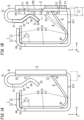
- a terminal device 1 is a so-called quick connection terminal, to which an electric wire 100 can be connected by the electric wire 100 being inserted thereto.
- the terminal device 1 includes a terminal portion 2 having electrical conductivity.
- the terminal portion 2 and the electric wire 100 are electrically connected to each other by the electric wire 100 coming into contact with the terminal portion 2.
- FIG. 1A illustrates only the terminal device 1 in a state where the electric wire 100 is not connected
- FIG. 1B illustrates the terminal device 1 and the electric wire 100 in a state where the electric wire 100 is connected, partially indicated by imaginary lines (two-dot chain lines).
- the terminal device 1 may be used for a wiring apparatus such as a switch or an outlet.
- a wiring apparatus 10 with the terminal device 1 (refer to FIG. 8 ) will be explained in a column of "(2.7) Wiring Apparatus" described later.
- the terminal device 1 includes a pressing portion 3 and a locking portion 4 in addition to the terminal portion 2.
- the electric wire 100 entering from an insertion port 11 is inserted between the terminal portion 2 and the pressing portion 3, the electric wire 100 is electrically connected to the terminal portion 2.
- the terminal portion 2 and the locking portion 4 movement of the electric wire 100 toward the insertion port 11 is restricted by the locking portion 4, and accordingly, the electric wire 100 is locked.
- the insertion port 11 mentioned herein is a space which the electric wire 100 passes through to be introduced between the terminal portion 2 and both of the pressing portion 3 and the locking portion 4, the terminal device 1 is not needed to have the insertion port 11 with an entity, and may have only a function as the insertion port 11.
- the insertion port 11 may be an insertion-hole 81 (refer to FIG. 5 ) with an entity, which is formed in a casing 8 (refer to FIG. 5 ) described later.
- the electric wire 100 When the electric wire 100 is an insulated wire where a core wire made of a conductor is covered with an insulation coating, an end of the electric wire 100 from which the insulation coating is peeled off, namely only the core wire, is inserted from the insertion port 11.
- the electric wire 100 may be any of a single wire where the core wire is formed of a single conductor wire, and a stranded wire where the core wire is formed of two or more conductor wires.
- terminal device 1 a basic configuration of the terminal device 1 will be described in detail with reference to FIGS. 1A to 4B .
- a "facing direction” in which the terminal portion 2 and the pressing portion 3 face each other is defined as an X axis direction, and a direction of directing to the terminal portion 2, when viewed from the pressing portion 3, is defined as a positive direction of an X axis.
- an "inserting direction” in which the electric wire 100 is inserted is defined as a Y axis direction, and a direction of inserting the electric wire 100 is defined as a positive direction of a Y axis.
- a direction in which two electric wires 100 connected to the terminal device 1 are arranged is defined as a Z axis direction (i.e., a direction perpendicular to a paper face of FIG. 1A ), and a direction of directing to the front side of the paper face of FIG. 1A is defined as a positive direction of a Z axis.
- the purpose of those directions is not to restrict a use direction of the terminal device 1.
- Arrows indicating the directions of the X axis, the Y axis and the Z axis in the figures are illustrated merely for convenience of explanation, and the arrows each do not have an entity.
- a matter that the facing direction and the inserting direction are exactly orthogonal to each other (cross at an angle of 90°) is not an essential constituent for the terminal device 1 as long as those directions cross each other.
- the terminal device 1 is a bipolar type of terminal device that is connectable with at most two electric wires 100. That is, since the terminal device 1 has two insertion ports 11, two electric wires 100 can be simultaneously connected through the two insertion ports 11, respectively. In the terminal device 1, since the two electric wires 100 are electrically connected to the single terminal portion 2, the two electric wires 100 connected in the terminal device 1 are electrically connected to each other via the terminal portion 2.
- the terminal device 1 may be therefore used as a feed terminal, for example.
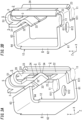
- the terminal device 1 includes two members: a terminal block 12; and a spring block 13.
- the terminal block 12 and the spring block 13 are respectively provided as different members. In other words, the terminal block 12 and the spring block 13 are members independently separated from each other.
- the terminal portion 2 and the pressing portion 3 are included in the terminal block 12.
- the locking portion 4 is included in the spring block 13.
- the terminal block 12 is formed of a metal plate having electrical conductivity.
- the spring block 13 is formed of a metal plate having elasticity.
- the terminal block 12 (pressing portion 3) and the spring block 13 (locking portion 4) are made of materials different from each other, respectively.
- the spring block 13 is combined with the terminal block 12 so as to be housed in a space surrounded by the terminal block 12.
- the terminal block 12 includes a connecting portion 5 and a holding portion 6, in addition to the terminal portion 2 and the pressing portion 3.
- the connecting portion 5 is to join the terminal portion 2 and the pressing portion 3.
- the connecting portion 5 joins: an end on an opposite side, of the terminal portion 2, from the insertion ports 11 in the Y axis direction; and the pressing portion 3.
- ends (upper ends in FIG. 3A ) on opposite sides, of the terminal portion 2 and the pressing portion 3, from the insertion ports 11 in the Y axis direction are joined to each other by the connecting portion 5.
- the terminal block 12 is made of copper (Cu) for example.
- the terminal device 1 is a bipolar type, the pressing portion 3 is provided in plural and the connecting portion 5 is also provided in plural (two pressing portions 3 and two connecting portions 5 in this embodiment).
- the terminal device 1 has a configuration that is in plane symmetry with respect to the Z axis direction in which two pressing portions 3 (or two connecting portions 5) are arranged. For this reason, hereinafter, unless otherwise noted, only one of the two pressing portions 3 will be explained, and explanation of the other of the two pressing portions 3 will be appropriately omitted. Similarly, only one of the two connecting portions 5 will be explained, and explanation of the other of the two connecting portions 5 will be appropriately omitted.
- the pressing portions 3, the connecting portions 5, the terminal portion 2 and the holding portion 6 are integrally formed.
- the terminal portion 2, the two pressing portions 3, the two connecting portions 5 and the holding portion 6 are made of a sheet of metal plate.
- the terminal portion 2, pressing portions 3, connecting portions 5 and holding portion 6, which constitute the terminal block 12, are formed by a sheet of metal plate being subjected to punching and bending.
- the terminal portion 2 has a rectangular plate shape.
- the terminal portion 2 is configured so that one surface 20 in a thickness direction thereof (X axis direction) faces the pressing portions 3. That is, the electric wire 100 inserted from the insertion port 11 is introduced between the one surface 20 of the terminal portion 2 and a corresponding pressing portion 3, and electrically connected to the terminal portion 2 so as to be in contact with the one surface 20 of the terminal portion 2.
- the terminal portion 2 is provided in the one surface 20 with a guide groove 23 that extends in the Y axis direction.
- the guide groove 23 restricts movement of the electric wire 100 toward directions other than the Y axis direction, in a plane (Y-Z plane) along the one surface 20, thereby limiting a moving direction of the electric wire 100 to only the Y axis direction.
- the guide grooves 23 is provided in two so as to respectively correspond to two electric wires 100, and two guide grooves 23 are formed in the one surface 20 of the terminal portion 2.
- the two guide grooves 23 are respectively arranged at both ends of the one surface 20 in the Z axis direction.
- Each guide groove 23 has a bottom surface 231 that is shaped so that a cross-sectional shape of the bottom surface 231 perpendicular to the inserting direction is curved convexly toward the positive direction of the X axis.
- each guide groove 23 is formed by curving part of the terminal portion 2.
- the terminal portion 2 is provided in a central region of the one surface 20 with an opening window 24 that penetrates the terminal portion 2 in the thickness direction thereof.
- the opening window 24 has a rectangular opened shape.
- the opening window 24 is a hole which part of a release member 9 described later is made to pass through.
- each pressing portion 3 is disposed at a position of facing a first region 21 of the one surface 20 of the terminal portion 2 in the X axis direction (the facing direction).
- the first region 21 mentioned herein is a region facing a corresponding pressing portion 3, of the one surface 20 of the terminal portion 2.
- Each pressing portion 3 is configured to hold an electric wire 100 inserted along the Y axis direction from the insertion port 11 so that the electric wire 100 is sandwiched between itself and the first region 21.
- the pressing portion 3 applies to the electric wire 100 a force in a direction of pressing the electric wire 100 against the one surface 20. That is, the electric wire 100 is pressed against the first region 21 of the one surface 20 of the terminal portion 2 by the pressing portion 3, which can generate a proper contact pressure between the terminal portion 2 and the electric wire 100.
- Each pressing portion 3 includes a first pressing piece 31, a second pressing piece 32 and a third pressing piece 33.
- the first pressing piece 31, second pressing piece 32 and third pressing piece 33 are arranged along the Y axis direction in order of the first pressing piece 31, second pressing piece 32 and third pressing piece 33 from the side of the connecting portion 5 (i.e., the side opposite from the insertion port 11).
- the first pressing piece 31 has a rectangular plate shape, and is substantially parallel to the one surface 20 of the terminal portion 2. An end on an opposite side, of the first pressing piece 31, from the insertion port 11 in the Y axis direction is connected with the connecting portion 5. Another end of the first pressing piece 31 on the side of the insertion port 11 in the Y axis direction is connected with the second pressing piece 32.
- the second pressing piece 32 has a rectangular plate shape, and is inclined relative to the one surface 20 of the terminal portion 2 so as to be closer to the terminal portion 2 as approaching the insertion port 11 in the Y axis direction. An end on an opposite side, of the second pressing piece 32, from the first pressing piece 31 in the Y axis direction is connected with the third pressing piece 33.
- the third pressing piece 33 has a rectangular plate shape, and is inclined relative to the one surface 20 of the terminal portion 2 so as to be closer to the terminal portion 2 as separated from the insertion port 11 in the Y axis direction.
- the third pressing piece 33 has a structure that a cross-sectional shape thereof perpendicular to the Z axis direction is approximately a V-shape together with the second pressing piece 32.
- a contact portion 34 which joins the second pressing piece 32 and the third pressing piece 33, is at a position closest to the one surface 20 of the terminal portion 2.
- the pressing portion 3 includes the contact portion 34 curved convexly toward the terminal portion 2 in the X axis direction, in a plane (X-Y plane) including both of the X axis direction and the Y axis direction.
- the contact portion 34 is curved at a prescribed radius of curvature.
- each connecting portion 5 is projected toward a direction opposite to the insertion port 11 from an end on the opposite side, of the terminal portion 2, from the insertion port 11 in the Y axis direction. That is, the terminal portion 2 and each pressing portion 3 are joined to each other by the connecting portion 5 provided so as to be projected in the positive direction of the Y axis from the ends (upper ends in FIG. 3A ) on the opposite side, thereof, from the insertion port 11 in the Y axis direction.
- Each connecting portion 5 includes a curved part 51.
- the curved part 51 is curved convexly toward a direction opposite to the insertion port 11 in the Y axis direction, in a plane (X-Y plane) including both of the X axis direction and the Y axis direction.
- the curved part 51 is curved like a circular arc shape.
- the curved part 51 has an internal diameter that is approximately equal to a distance between the first pressing piece 31 of the pressing portion 3 and the terminal portion 2.
- each connecting portion 5 is set so that a size thereof in the Z axis direction is smaller than a size of a corresponding pressing portion 3 in the Z axis direction. More specifically, the connecting portions 5 are not formed over the full length of the terminal portion 2 in the Z axis direction, but formed so as to avoid interference with regions, in which the guide grooves 23 are formed, of the terminal portion 2. Accordingly, each connecting portion 5 can have a lower elastic coefficient and can be more easily bent, compared with a case where the size of each connecting portion 5 in the Z axis direction is equal to the size of the corresponding pressing portion 3 in the Z axis direction.
- the holding portion 6 is formed integrally with the terminal portion 2, and configured so as to hold, between itself and the terminal portion 2, the locking portion 4 (spring block 13).
- the holding portion 6 is provided so as to be projected from an end on an opposite side, of the terminal portion 2, from the connecting portions 5 in the Y axis direction. That is, the holding portion 6 is connected with the end (lower end in FIG. 3A ) of the terminal portion 2 on the side of the insertion port 11 in the Y axis direction.
- the holding portion 6 includes a first holding piece 61, a second holding piece 62 and a third holding piece 63.
- the first holding piece 61, second holding piece 62 and third holding piece 63 are continuously arranged in order of the first holding piece 61, second holding piece 62 and third holding piece 63 from the side of the terminal portion 2.
- all of: a part of joining the terminal portion 2 and the first holding piece 61; a joining part between the first and second holding pieces 61 and 62; and a joining part (a restricting part 64) between the second and third holding pieces 62 and 63 are curved at a prescribed radius of curvature.
- the first holding piece 61 has a rectangular plate shape, and is projected in the negative direction of the X axis from the terminal portion 2.
- the first holding piece 61 and the terminal portion 2 are substantially orthogonal to each other.
- An end on an opposite side, of the first holding piece 61, from the terminal portion 2 in the X axis direction is connected with the second holding piece 62.
- the second holding piece 62 has a rectangular plate shape, and is projected in the positive direction of the Y axis from the first holding piece 61.
- the second holding piece 62 and the first holding piece 61 are substantially orthogonal to each other.
- An end on an opposite side, of the second holding piece 62, from the first holding piece 61 in the Y axis direction is connected with the third holding piece 63.
- the third holding piece 63 has a rectangular plate shape, and is projected in the positive direction of the X axis from the second holding piece 62.
- the third holding piece 63 and the second holding piece 62 are substantially orthogonal
- the holding portion 6 positions the spring block 13 by the restricting part 64 that is a part of joining the second and third holding pieces 62 and 63.
- a dimensional relationship between the second holding piece 62 and the terminal portion 2 is defined so that those lengths in the Y axis direction are approximately the same as each other.
- the holding portion 6 therefore has a structure that a cross-sectional shape thereof perpendicular to the Z axis direction is approximately a rectangular frame shape together with the terminal portion 2.
- the spring block 13 is housed in a space surrounded by the holding portion 6 and the terminal portion 2.
- a dimensional relationship between the first holding piece 61 and the third holding piece 63 is defined so that, in the X axis direction, a size of the third holding piece 63 is smaller than a size of the first holding piece 61, thereby forming a gap between the third holding piece 63 and the terminal portion 2.
- the pressing portion 3 is introduced through this gap into the space between the second holding piece 62 and the terminal portion 2.
- the first holding piece 61 is provided with a cutout-hole 611 that penetrates the first holding piece 61 in a thickness direction thereof.
- the cutout-hole 611 is disposed at a position corresponding to the insertion port 11.
- the electric wire 100 inserted from the insertion port 11 can be therefore introduced through the cutout-hole 611 into the space surrounded by the holding portion 6 and the terminal portion 2.
- the cutout-hole 611 is provided in two so as to respectively correspond to two electric wires 100, and two cutout-holes 611 are formed in the first holding piece 61.
- the two cutout-holes 611 are respectively disposed at both ends of the first holding piece 61 in the Z axis direction.
- the first holding piece 61 is provided in a central part thereof with a through-hole 612 that penetrates the first holding piece 61 in the thickness direction thereof.
- the through-hole 612 has a circular opened shape. Since the through-hole 612 is not an essential constituent for the terminal device 1, the through-hole 612 may be omitted.
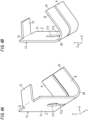
- the spring block 13 includes an extending portion 7 in addition to the locking portion 4.
- the spring block 13 is made of Steel Special Use Stainless (SUS) for example.
- the spring block 13 is formed of a metal plate thinner than the terminal block 12.
- the terminal device 1 since the terminal device 1 is a bipolar type, the locking portion 4 is provided in plural (in this embodiment, two locking portions).
- the terminal device 1 has a configuration that is in plane symmetry with respect to the Z axis direction in which two locking portions 4 are arranged. For this reason, hereinafter, unless otherwise noted, only one of the two locking portions 4 will be explained and explanation of the other of the two locking portions 4 will be appropriately omitted.
- the locking portions 4 and the extending portion 7 are integrally formed.
- the two locking portions 4 and the extending portion 7 are made of a sheet of metal plate.
- the locking portions 4 and extending portion 7, which constitute the spring block 13, are formed by a sheet of metal plate being subjected to punching and bending.
- each locking portion 4 is disposed at a position of facing a second region 22 of the one surface 20 of the terminal portion 2 in the X axis direction (the facing direction).
- the second region 22 mentioned herein is a region that is different from the first region 21, of the one surface 20 of the terminal portion 2, in the Y axis direction, and faces the locking portion 4.
- the second region 22 is disposed between the first region 21 and the insertion port 11 in the Y axis direction. That is, the first region 21 and the second region 22 are arranged along the Y axis direction in order of the second region 22 and the first region 21 from the side of the insertion port 11.
- Each locking portion 4 is configured to restrict movement of the electric wire 100 toward the insertion port 11 by contact with the electric wire 100 inserted along the Y axis direction from the insertion port 11.
- the locking portion 4 is configured to sandwich the electric wire 100 between itself and the second region 22. That is, the electric wire 100 is pressed against the second region 22 of the one surface 20 of the terminal portion 2 by the locking portion 4, which can generate a proper contact pressure between the terminal portion 2 and the electric wire 100.
- each locking portion 4 has a rectangular plate shape, and is inclined relative to the one surface 20 of the terminal portion 2 so as to be closer to the terminal portion 2 as separated from the insertion port 11 in the Y axis direction.
- Each locking portion 4 is configured to restrict the movement of the electric wire 100 toward the insertion port 11 by the locking portion 4 being, at an end edge 41 thereof closest to the one surface 20 of the terminal portion 2, in contact with the electric wire 100.
- each locking portion 4 is projected, from a part (spring part 42) joining the each locking portion 4 and the extending portion 7, in a direction (i.e., the positive direction of the Y axis) in which the electric wire 100 is inserted, and inclined relative to the one surface 20 of the terminal portion 2 so as to make the end edge 41 closer to the one surface 20 of the terminal portion 2. While the electric wire 100 is introduced between the one surface 20 of the terminal portion 2 and the locking portion 4, the end edge 41 of the locking portion 4 is in contact with the electric wire 100.
- the extending portion 7 is projected, in a direction opposite to the insertion port 11, from ends (lower ends in FIG. 4A ) of the locking portions 4 on the side of the insertion port 11 in the Y axis direction.
- the extending portion 7 is constituted by part of the spring block 13, which extends in the positive direction of the Y axis from an end on an opposite side, of the locking portion 4, from the end edge 41.
- the spring part 42 which is a part of joining the locking portion 4 and the extending portion 7, applies an elastic force to the locking portion 4.
- the spring block 13 includes the spring part 42 curved convexly toward the side of the insertion port 11 in the Y axis direction, in a plane (X-Y plane) including both of the X axis direction and the Y axis direction.
- the spring part 42 is curved at a prescribed radius of curvature.
- the extending portion 7 includes a first extending piece 71 and a second extending piece 72.
- the first extending piece 71 and the second extending piece 72 are connected with each other in order of the first extending piece 71 and the second extending piece 72 from the side of the locking portion 4.
- the first extending piece 71 has a rectangular plate shape, and as shown in FIGS. 1A and 1B , is approximately parallel to the one surface 20 of the terminal portion 2. An end of the first extending piece 71 on a side of the insertion port 11 in the Y axis direction is connected with the locking portion 4. Another end on an opposite side, of the first extending piece 71, from the locking portion 4 in the Y axis direction is connected with the second extending piece 72.
- the second extending piece 72 has a rectangular plate shape, and is projected in the positive direction of the X axis from the first extending piece 71.
- the second extending piece 72 and the first extending piece 71 are substantially orthogonal to each other.
- the second extending piece 72 has a structure that a cross-sectional shape thereof perpendicular to the Z axis direction is approximately an L-shape together with the first extending piece 71.
- the spring block 13 is positioned with respect to the terminal block 12 by making a corner 73, which is a part of joining the first and second extending pieces 71 and 72, come into contact with the restricting part 64 of the terminal block 12.
- the corner 73 is always not in contact with the restricting part 64, but there is a gap between the corner 73 and the restricting part 64.
- the corner 73 comes into contact with the restricting part 64, and the movement of the spring block 13 can be accordingly restricted. Therefore, the spring block 13 is positioned with respect to the terminal block 12.
- the corner 73 is curved at a prescribed radius of curvature.
- a size of the spring block 13 in the Y axis direction is defined so as to be slightly smaller than a distance between the first holding piece 61 and the third holding piece 63 of the terminal block 12.
- a size of the spring block 13 in the X axis direction is defined so as to be slightly larger than a distance between the terminal portion 2 and the second holding piece 62 of the terminal block 12. Accordingly, the spring block 13 is slightly loosely positioned in the Y axis direction, and can be housed in a space surrounded by the holding portion 6 and the terminal portion 2 so as to be in a compressed state in the X axis direction.
- the spring part 42 is elastically deformed so as to cause the end edges 41 of the locking portions 4 to be closer to the first extending piece 71, and the spring block 13 accordingly falls into the compressed state in the X axis direction.
- a dimensional relationship between the second extending piece 72 and the third holding piece 63 is defined so that those lengths in the X axis direction are approximately equal to each other, which can form, between the second extending piece 72 and the terminal portion 2, a gap for introducing the pressing portion 3 between the second holding piece 62 and the terminal portion 2.
- the first extending piece 71 is provided in a central part thereof with a through-hole 711 that penetrates the first extending piece 71 in a thickness direction thereof.
- the through-hole 711 has a circular opened shape.
- the first extending piece 71 is further provided with a slit 712 that penetrates the first extending piece 71 in the thickness direction thereof and extends from the through-hole 711 toward the locking portions 4.
- the slit 712 extends to the end edges 41 of the locking portions 4 through the spring part 42.
- the two locking portions 4 are separated from each other in the Z axis direction by the slit 712. Since the through-hole 711 is not an essential constituent for the terminal device 1, the through-hole 711 may be omitted.
- a first distance L1 is set so as to be larger than a second distance L2, where the first distance L1 represents a distance between each pressing portion 3 and a corresponding first region 21, and the second distance L2 represents a distance between each locking portion 4 and a corresponding second region 22.
- the terminal portion 2 is provided in the one surface 20 with the guide grooves 23, the first and second distances L1 and L2 mentioned above and a third distance L3 mentioned later are all defined based on a bottom surface 231 that is the deepest part of each guide groove 23, as a reference.
- the first distance L1 is a distance between: the contact portion 34, which is at a position closest to the one surface 20 of the terminal portion 2, of each pressing portion 3; and the bottom surface 231 that is the deepest part of the corresponding guide groove 23 in the first region 21 of the terminal portion 2.
- the second distance L2 is a distance between: the end edge 41, which is at a position closest to the one surface 20 of the terminal portion 2, of each locking portion 4; and the bottom surface 231 that is the deepest part of the corresponding guide groove 23 in the second region 22 of the terminal portion 2.
- each pressing portion 3 namely the third pressing piece 33 is inclined relative to the one surface 20 of the terminal portion 2 so as to be further separated from the terminal portion 2 as approaching the insertion port 11 in the Y axis direction. That is, the third pressing piece 33 is inclined so as to be further separated from the terminal portion 2 as separated from the contact portion 34. Accordingly, a distance between: an end edge on the opposite side, of the third pressing piece 33, from the contact portion 34; and the terminal portion 2 is larger than a distance between the contact portion 34 and the terminal portion 2.
- a distance between: the end edge on the opposite side, of the third pressing piece 33, from the contact portion 34; and the bottom surface 231 that is the deepest part of the corresponding guide groove 23 of the terminal portion 2 is defined as the third distance L3.
- the relationship between the first, second and third distances L1, L2 and L3 meets that the first distance L1 is larger than the second distance L2, and the third distance L3 is larger than the first distance L1 (L2 ⁇ L1 ⁇ L3).
- the electric wire 100 to be inserted from the insertion port 11 preferably has a wire diameter ⁇ X that is more than the first distance L1 and less than the third distance L3.
- the wire diameter ⁇ X of the electric wire 100 mentioned herein is a wire diameter ⁇ X of an electric wire 100 defined as an electric wire connectable with the terminal device 1.
- the wire diameter ⁇ X corresponds to a diameter of a core wire to be inserted from the insertion port 11.
- first, second and third distances L1, L2 and L3 and the wire diameter ⁇ X meets that the first distance L1 is larger than the second distance L2, and the wire diameter ⁇ X is larger than the first distance L1, and the third distance L3 is larger than the wire diameter ⁇ X (L2 ⁇ L1 ⁇ ⁇ X ⁇ L3).
- the wire diameter ⁇ X mentioned herein means an outer diameter of the electric wire 100 to be inserted from the insertion port 11 (a diameter of the core wire in the case of the insulated wire), and may be appropriately determined in accordance with, for example, IEC (International Electrotechnical Commission) standard or the like.
- a worker inserts the electric wire 100 as a connected target into the terminal device 1 through the insertion port 11 in the positive direction of the Y axis.
- an end of the electric wire 100 is first introduced between the locking portion 4 and the terminal portion 2 (the second region 22).
- the second distance L2 and the wire diameter ⁇ X of the electric wire 100 have the dimensional relationship of "L2 ⁇ ⁇ X", as described in the column of "(2.4) Dimensional Relationship".
- the locking portion 4 is pressed by the end of the electric wire 100, and the end edge 41 of the locking portion 4 is displaced in a direction of being separated from the one surface 20 of the terminal portion 2.
- the spring part 42 is elastically deformed so that its radius of curvature is reduced.
- the locking portion 4 therefore applies, to the electric wire 100, a force in a direction of pressing the electric wire 100 against the terminal portion 2.
- the end of the electric wire 100 is introduced between the pressing portion 3 and the terminal portion 2 (the first region 21).
- the first distance L1, the third distance L3 and the wire diameter ⁇ X of the electric wire 100 have the dimensional relationship of "L1 ⁇ ⁇ X ⁇ L3", as described in the column of "(2.4) Dimensional Relationship".
- the end of the electric wire 100 is guided by the third pressing piece 33 so as to be introduced between the contact portion 34 and the terminal portion 2.
- the contact portion 34 is then pressed by the end of the electric wire 100, and the contact portion 34 of the pressing portion 3 is therefore displaced in a direction of being separated from the one surface 20 of the terminal portion 2.
- the connecting portion 5 is elastically deformed so that a radius of curvature of the curved part 51 is increased.
- the pressing portion 3 therefore applies, to the electric wire 100, a force in a direction of pressing the electric wire 100 against the terminal portion 2.
- a positional relationship between the locking portion 4 and the pressing portion 3, and a size of each of the locking portion 4 and the pressing portion 3 are defined so that the locking portion 4 does not come into contact with the pressing portion 3 when the end edge 41 of the locking portion 4 is displaced in a direction of being separated from the one surface 20 of the terminal portion 2.
- the positional relationship between the locking portion 4 and the pressing portion 3 in the Y axis direction, and the size of each of the locking portion 4 and the pressing portion 3 are defined so that the pressing portion 3 is not disposed on a locus of the end edge 41 of the locking portion 4.
- the locking portion 4 and the pressing portion 3 are not simultaneously displaced, but the locking portion 4 is first displaced and the pressing portion 3 is then displaced. Accordingly, the magnitude of a force required for inserting the electric wire 100 can be more reduced, compared with a configuration that the locking portion 4 and the pressing portion 3 are simultaneously displaced.
- a distance between the first region 21 and the second region 22 in the Y axis direction is preferably made as small as possible.
- a length of the electric wire 100 which should be inserted can be reduced by reducing the distance between the first region 21 and the second region 22, which can downsize the terminal device 1.
- the terminal device 1 includes the casing 8 and the release member 9, in addition to the above-mentioned terminal block 12 and spring block 13.
- the casing 8 is made of material having electric insulation, such as synthetic resin.
- the casing 8 is shaped like a box that has a space for housing the terminal block 12 and the spring block 13. In a state where the terminal block 12 and the spring block 13 have been housed in the casing 8, at least the holding portion 6 is fixed to the casing 8.
- the box-shaped casing 8 is illustrated, which are opened in two directions of the positive direction of the Y axis and the positive direction of the Z axis.
- the casing 8 is provided with an insertion-hole 81 that is disposed at a position corresponding to the insertion port 11, of the casing 8, and penetrates a bottom plate of the casing 8 in the Y axis direction.
- the insertion-hole 81 has a circular opened shape, and is provided in two so as to correspond to two electric wires 100. Although illustration of the insertion port 11 is omitted in FIGS. 5 to 6B , the insertion-hole 81 of the casing 8 corresponds to the insertion port 11 in the terminal device 1 with the casing as above.
- the casing 8 is provided with an operational window 82 that is disposed at a position corresponding to the opening window 24, of the casing 8, and penetrates a side wall of the casing 8 in the X axis direction.
- the operational window 82 is a hole which an action part 93 of the release member 9 described later is made to pass through.
- the casing 8 is provided with a pair of bearing parts 83 for holding the release member 9, and the bearing parts 83 are respectively formed in inside surfaces, which are paired and face each other in the Z axis direction, of inside surfaces of the operational window 82.
- a shaft part 91 of the release member 9 as described later is inserted in the pair of bearing parts 83.
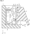
- the release member 9 is a member for releasing the restriction of the movement of the electric wire 100, performed by the locking portion 4, namely the locking of the electric wire 100 by the locking portion 4.
- the release member 9 is made of material having electric insulation, such as synthetic resin.
- the release member 9 is configured to be movable relatively to the terminal portion 2 between a normal position and a release position.
- the release member 9 is configured to apply, when moved from the normal position to the release position, a force to the locking portion 4 in a direction of being separated from the second region 22 so as to release the restriction (the locking) of the movement of the electric wire 100 by the locking portion 4.
- FIGS. 6A to 7 show a state where the release member 9 is at the normal position.
- the release member 9 includes the shaft part 91, an operational part 92 and the action part 93.
- the shaft part 91 has a columnar shape extending along the Z axis direction.
- the release member 9 is held by the casing 8 in a state where the release member 9 can be turned around the shaft part 91 with respect to the casing 8, by both ends of the shaft part 91 in the Z axis direction being respectively inserted into the paired bearing parts 83.
- the release member 9 can be turned (moved) between the normal position and the release position around the shaft part 91.
- the operational part 92 is a part to be operated for moving the release member 9 from the normal position to the release position.
- the release member 9 is held by the casing 8 so that at least part of the operational part 92 is exposed from the casing 8.
- the action part 93 is a part for applying to the locking portion 4 a force in a direction of being separated from the second region 22, when the release member 9 is moved from the normal position to the release position.
- the release member 9 is held by the casing 8 so that at least part of the action part 93 is made to face the end edge 41 of the locking portion 4 through the operational window 82 of the casing 8 and the opening window 24 of the terminal portion 2.
- the worker when the connection between the terminal device 1 and the electric wire 100 is released, the worker operates the release member 9 to release the locking of the electric wire 100, performed by the locking portion 4, and accordingly, can pull out the electric wire 100 from the insertion port 11. That is, when the worker pushes the operational part 92 in a direction shown by an arrow A1 in FIG. 7 from the state where the release member 9 is at the normal position, the release member 9 is turned around the shaft part 91, and moved to the release position. At this time, the action part 93 is moved in a direction shown by an arrow A2 in FIG. 7 , and applies to the end edge 41 of the locking portion 4 a force in a direction of being separated from the second region 22. When the end edge 41 is moved in the direction of being separated from the second region 22, the locking portion 4 is separated from the electric wire 100. The restriction (the locking) of the movement of the electric wire 100 by the locking portion 4 can be therefore released.
- the terminal device 1 in this embodiment is configured so that a force is applied from the single release member 9 simultaneously to the two locking portions 4. That is, the action part 93 of the release member 9 is disposed at a position over the two locking portions 4 in the Z axis direction.
- the release member 9 is moved from the normal position to the release position, the force in the direction of being separated from the second region 22 is applied simultaneously to the two locking portions 4, and the locking by the two locking portions 4 is simultaneously released.
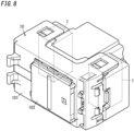
- the terminal device 1 with the above-mentioned configuration can be used for a wiring apparatus 10 as shown in FIG. 8 , for example.
- the wiring apparatus 10 illustrated in FIG. 8 is a switch to be attached to a wall in a building or the like and to be used.
- the wiring apparatus 10 includes: an apparatus body 101 having a rectangular parallelepiped shape; and the terminal device 1 housed in the apparatus body 101.
- the apparatus body 101 is provided on a front surface thereof with a handle 102.
- the wiring apparatus 10 is configured so that a contact point in the apparatus body 101 is switched on/off whenever the handle 102 is pushed.
- the wiring apparatus 10 includes two terminal devices 1, each of which is the terminal device 1 with the above-mentioned configuration.
- the two terminal devices 1 are housed in the apparatus body 101 so that insertion-holes 81 (refer to FIG. 5 ) thereof are exposed on a rear surface of the apparatus body 101. Accordingly, in the wiring apparatus 10, connection of the electric wire 100 can be achieved by the electric wire 100 being inserted from the side of the rear surface of the apparatus body 101.
- the casing 8 (refer to FIG. 5 ) of the terminal device 1 may be a member independently separated from a case body of the apparatus body 101, or may be part of the case body of the apparatus body 101.
- the release member 9 (refer to FIG. 7 ) is held by the case body of the apparatus body 101 or the casing 8 so that at least part of the operational part 92 (refer to FIG. 7 ) is exposed from the case body of the apparatus body 101.
- a terminal device 1 includes a terminal portion 2, a pressing portion 3, a locking portion 4 and a connecting portion 5.
- the pressing portion 3 is disposed to face one surface 20 of the terminal portion 2, and configured to hold an electric wire 100 inserted along an inserting direction (Y axis direction) from an insertion port 11 so that the electric wire 100 is sandwiched between the pressing portion 3 and the terminal portion 2.
- the locking portion 4 is elastic; disposed to face the one surface 20 of the terminal portion 2; and configured to restrict movement of the electric wire 100 toward the insertion port 11 by contact with the electric wire 100.
- the connecting portion 5 joins the terminal portion 2 and the pressing portion 3.
- the electric wire 100 is held at two positions: between the pressing portion 3 and the terminal portion 2; and between the locking portion 4 and the terminal portion 2, the electric wire 100 is suppressed from being inclined with respect to the inserting direction (Y axis direction).
- the electric wire 100 can be brought into surface-contact with the terminal portion 2 regardless of hardness of the electric wire 100, which can stabilize a contact state between the electric wire 100 and the terminal portion 2.
- the stabilization of the contact state between the electric wire 100 and the terminal portion 2 can lead to a stabilization of a contact resistance between the electric wire 100 and the terminal portion 2, and therefore, an increase in temperature of the terminal portion 2 can be suppressed by an increase in the contact resistance.
- the pressing portion 3 of pressing the electric wire 100 against the terminal portion 2 by sandwiching the electric wire 100 between itself and the terminal portion 2 is joined to the terminal portion 2 by the connecting portion 5.
- the pressing portion 3 can be treated as a single component together with the terminal portion 2.
- the force of pressing the electric wire 100 against the terminal portion 2 is further suppressed from varying, compared with a case where the terminal portion 2 and the pressing portion 3 are components independently separated from each other. Therefore, the terminal device 1 has an advantage that the contact state of the electric wire 100 in contact with the terminal portion 2 can be suppressed from falling into an unstable state.
- the locking portion 4 in the first aspect, in the inserting direction (Y axis direction), the locking portion 4 is preferably disposed between the pressing portion 3 and the insertion port 11. According to this configuration, the locking portion 4 locks the electric wire 100 at a position close to the insertion port 11, and the pressing portion 3 presses the electric wire 100 against the terminal portion 2 at a position far from the insertion port 11. Accordingly, even when a force in a direction perpendicular to the inserting direction (Y axis direction) is applied to the electric wire 100, the force of pressing the electric wire 100 against the terminal portion 2 is stabilized, and the contact state between the terminal portion 2 and the electric wire 100 can be easily stabilized. Note that this configuration is not an essential constituent for the terminal device 1, and for example, the pressing portion 3 may be disposed between the locking portion 4 and the insertion port 11 in the inserting direction (Y axis direction).
- the connecting portion 5 joins: an end of the terminal portion 2 on an opposite side from the insertion port 11 in the inserting direction (Y axis direction); and an end of the pressing portion 3 on an opposite side from the insertion port 11 in the inserting direction (Y axis direction). According to this configuration, the electric wire 100 inserted from the insertion port 11 can be suppressed from interfering with the connecting portion 5, and the flexibility of design of the connecting portion 5 can be enhanced.
- the connecting portion 5 is preferably projected, toward a direction opposite to the insertion port 11, from the end on the opposite side, of the terminal portion 2, from the insertion port 11 in the inserting direction (Y axis direction). According to this configuration, since a distance between the pressing portion 3 and a fulcrum when the pressing portion 3 is displaced is increased depending on a projected amount of the connecting portion 5, it is possible to sufficiently secure a displacement amount of the pressing portion 3 while reducing a deformed amount of the connecting portion 5. A selection width of a wire diameter ⁇ X of a connectable electric wire 100 can be therefore extended. Note that this configuration is not an essential constituent for the terminal device 1, and for example, the connecting portion 5 may not be projected from the end on the opposite side, of the terminal portion 2, from the insertion port 11 in the inserting direction (Y axis direction).
- the connecting portion 5 preferably includes a curved part 51, and the curved part 51 is preferably curved convexly toward the direction opposite to the insertion port 11 in the inserting direction, in a plane including both of the inserting direction and a facing direction in which the pressing portion 3 and the terminal portion 2 face each other.
- a stress applied to the connecting portion 5 upon the displacement of the pressing portion 3 is dispersed in the curved part 51, and the stress is therefore suppressed from being generated intensively in the connecting portion 5.
- the connecting portion 5 is suppressed from plastically deforming, and the pressing force of the pressing portion 3 can be easily maintained.
- this configuration is not an essential constituent for the terminal device 1, and for example, the connecting portion 5 may not include the curved part 51.
- a terminal device 1 in any one of the first to fourth aspects, preferably includes a plurality of the pressing portions 3 (two pressing portions in the case of the First Embodiment), each of which is configured to individually hold a corresponding electric wire 100 of a plurality of the electric wires 100 so that the corresponding electric wire 100 is sandwiched between the each pressing portion 3 and the terminal portion 2.
- the pressing portions 3 individually applies a pressing force to a corresponding electric wire 100 of a plurality of the electric wires 100 respectively inserted from a plurality of the insertion ports 11, the followability of the pressing portions 3 to the electric wires 100 can be improved, and the contact state between the electric wires 100 and the terminal portion 2 can be stabilized.
- a single pressing portion 3 may be configured to hold a plurality of the electric wires 100, respectively inserted from a plurality of the insertion ports 11, between the single pressing portion 3 and the terminal portion 2.
- the pressing portion 3, the connecting portion 5 and the terminal portion 2 are preferably integrally formed. According to this configuration, since the pressing portion 3 is electrically conductive to the terminal portion 2 via the connecting portion 5, the electric wire 100 can be electrically connected to the terminal portion 2 even when brought into contact with any of the terminal portion 2 and the pressing portion 3. The contact resistance between the electric wire 100 and the terminal portion 2 can be therefore further stabilized. Note that this configuration is not an essential constituent for the terminal device 1, and for example, the pressing portion 3, the connecting portion 5 and the terminal portion 2 may be members independently separated from one another.
- the pressing portion 3 preferably includes a contact portion 34, and the contact portion 34 is curved convexly toward the terminal portion 2 in a facing direction in which the pressing portion 3 and the terminal portion 2 face each other, in a plane including both of the inserting direction and the facing direction.
- the electric wire 100 is moved in the inserting direction (Y axis direction)
- the electric wire 100 comes into contact with the contact portion 34 of the pressing portion 3
- the electric wire 100 is suppressed from being caught by the pressing portion 3.
- the electric wire 100 can be therefore smoothly inserted into or removed from the terminal device 1.
- this configuration is not an essential constituent for the terminal device 1, and for example, the pressing portion 3 may not include the curved contact portion 34.
- the locking portion 4 is preferably inclined relative to the one surface 20 of the terminal portion 2 so as to be closer to the terminal portion 2 as separated from the insertion port 11 in the inserting direction (Y axis direction).
- the locking portion 4 is preferably configured to restrict the movement of the electric wire 100 toward the insertion port 11 by the locking portion 4 being, at an end edge 41 thereof closest to the one surface 20 of the terminal portion 2, in contact with the electric wire 100.
- the locking portion 4 is pressed by an end of the electric wire 100, and the end edge 41 of the locking portion 4 is displaced in a direction of being separated from the one surface 20 of the terminal portion 2.
- the electric wire 100 can be therefore inserted without operation to the release member 9.
- this configuration is not an essential constituent for the terminal device 1, and for example, the locking portion 4 may have a shape different from the above-mentioned shape.
- the terminal portion 2 is preferably provided in the one surface 20 with a guide groove 23 extending in the inserting direction (Y axis direction).
- Y axis direction movement of the electric wire 100 to directions other than the inserting direction (Y axis direction) in a plane along the one surface 20 is restricted by the guide groove 23.
- Workability for inserting the electric wire 100 can be therefore improved.
- the electric wire 100 is a stranded wire with a core wire formed of two or more conductor wires, the conductor wires forming the core wire hardly fall apart by the electric wire 100 passing through the guide groove 23.
- this configuration is not an essential constituent for the terminal device 1, and for example, the guide groove 23 may be omitted.
- the guide groove 23 preferably has a bottom surface 231 that is shaped so that a cross-sectional shape of the bottom surface 231 perpendicular to the inserting direction (Y axis direction) is curved convexly toward a direction opposite to the pressing portion 3 in a facing direction in which the pressing portion 3 and the terminal portion 2 face each other.
- the electric wire 100 can be made so as to easily pass through a center of the guide groove 23 in a width direction thereof (Z axis direction).
- the guide groove 23 may have a bottom surface 231 formed like a V-shape.
- a terminal device 1 according to an eleventh aspect in any one of the first to tenth aspects, preferably further includes a release member 9 that is movable relatively to the terminal portion 2 between a normal position and a release position.
- the release member 9 is preferably configured to apply, when moved from the normal position to the release position, a force to the locking portion 4 in a direction of being separated from the one surface 20 of the terminal portion 2 so as to release restriction of movement of the electric wire 100 performed by the locking portion 4.
- the electric wire 100 can be easily pulled out in a state where the restriction of movement of the electric wire 100 performed by the locking portion 4 has been released by operating the release member 9.
- this configuration is not an essential constituent for the terminal device 1, and for example, the release member 9 may be omitted.
- the pressing portion 3 and the locking portion 4 are preferably members independently separated from each other. According to this configuration, the pressing portion 3 of pressing the electric wire 100 against the terminal portion 2 by sandwiching the electric wire 100 between itself and the terminal portion 2 is a member independently separated from the locking portion 4 of locking the electric wire 100. Accordingly, for example, even when a force is applied from the electric wire 100 to the locking portion 4 upon insertion of the electric wire 100, this force is not transmitted from the locking portion 4 to the pressing portion 3, and the force of pressing the electric wire 100 against the terminal portion 2 is therefore easily stabilized.
- the terminal device 1 has an advantage that the contact state of the electric wire 100 in contact with the terminal portion 2 can be suppressed from falling into an unstable state.
- this configuration is not an essential constituent for the terminal device 1, and for example, the pressing portion 3 and the locking portion 4 may be formed integrally with each other.
- a first distance L1 is preferably larger than a second distance L2, where the first distance L1 is a distance between the pressing portion 3 and the one surface 20 of the terminal portion 2, and the second distance L2 is a distance between the locking portion 4 and the one surface 20 of the terminal portion 2.
- the pressing portion 3 since an interval between the pressing portion 3 and the terminal portion 2 is wider than an interval between the locking portion 4 and the terminal portion 2, the pressing portion 3 hardly interrupts movement of the electric wire 100 in the inserting direction (Y axis direction), and the electric wire 100 can be therefore smoothly inserted/removed.
- this configuration is not an essential constituent for the terminal device 1, and for example, the first distance L1 may be equal to or smaller than the second distance L2.
- an end of the pressing portion 3 on a side of the insertion port 11 in the inserting direction is preferably inclined relative to the one surface 20 of the terminal portion 2.
- the end of the pressing portion 3 on the side of the insertion port 11 in the inserting direction is preferably inclined so as to be further separated from the terminal portion 2 as approaching the insertion port 11 in the inserting direction.
- this configuration upon insertion of the electric wire 100, an end of the electric wire 100 is guided by the end of the pressing portion 3 on the side of the insertion port 11 in the inserting direction (Y axis direction) so as to be introduced between the pressing portion 3 and the terminal portion 2, and accordingly, the insertion of the electric wire 100 can be easily achieved.
- this configuration is not an essential constituent for the terminal device 1, and for example, the end of the pressing portion 3 on the side of the insertion port 11 in the inserting direction (Y axis direction) may not be inclined relative to the one surface 20 of the terminal portion 2.
- a terminal device 1 in any one of the first to fourteenth aspects, preferably further includes a holding portion 6 that is formed integrally with the terminal portion 2, and the holding portion 6 is preferably configured to hold a spring block 13 including the locking portion 4 between the holding portion 6 and the terminal portion 2.
- the holding portion 6 since a relative position of the locking portion 4 with respect to the terminal portion 2 is determined by the holding portion 6, the electric wire 100 can be stably locked by the locking portion 4.
- the holding portion 6 is made of metal material, the relative position of the locking portion 4 with respect to the terminal portion 2 is hardly varied depending on a change in temperature or the like, compared with a case where the locking portion 4 is held by the casing 8 and the like made of synthetic resin, for example.
- this configuration is not an essential constituent for the terminal device 1, and for example, the holding portion 6 may be omitted and the spring block 13 may be held by the casing 8 and the like.
- the holding portion 6 preferably includes a restricting part 64.
- the restricting part 64 is preferably in contact with the spring block 13 on an opposite side of the spring block 13 from the insertion port 11 in the inserting direction (Y axis direction), and in contact with the spring block 13 on an opposite side of the spring block 13 from the terminal portion 2 in a facing direction (X axis direction) in which the pressing portion 3 and the terminal portion 2 face each other.
- this configuration since movement of the spring block 13 in a direction of being separated from the insertion port 11 and the terminal portion 2 is restricted by the restricting part 64, the spring block 13 is positionally stabilized upon the insertion of the electric wire 100, and accordingly, the electric wire 100 can be stably locked by the locking portion 4.
- this configuration is not an essential constituent for the terminal device 1, and for example, the restricting part 64 may be omitted and the movement of the spring block 13 may be restricted by the casing 8 and the like.
- the pressing portion 3 and the locking portion 4 are preferably made of materials different from each other, respectively. According to this configuration, it is possible to apply the best material for each of: the pressing portion 3 for pressing the electric wire 100 against the terminal portion 2; and the locking portion 4 for locking the electric wire 100. For example, it is possible to apply material having excellent electrical conductivity for the pressing portion 3, and material having excellent elasticity for the locking portion 4. Note that this configuration is not an essential constituent for the terminal device 1, and for example, the pressing portion 3 and the locking portion 4 may be made of the same material.
- a wiring apparatus 10 includes: the terminal device 1 according to any one of the first to seventeenth aspects; and an apparatus body 101 configured to house therein the terminal device 1. According to this configuration, the wiring apparatus 10 has an advantage that the contact state of the electric wire 100 in contact with the terminal portion 2 can be suppressed from falling into an unstable state.
- the terminal device 1 is not limited to be used for the wiring apparatus 10, but may be to be used for an electrical apparatus such as a home appliance, or the terminal device 1 may be used alone.
- the guide groove 23 is not limited to have the configuration that the part of the terminal portion 2 is formed to be curved as described in the First Embodiment, but may have a configuration that is formed by cutting the one surface 20 of the terminal portion 2 through a cutting process, for example.
- the terminal portion 2, pressing portion 3, connecting portion 5 and holding portion 6, which constitute the terminal block 12, are not limited to have the configuration that is formed by bending a single metal plate, but may be formed through an extrusion molding process or the like, for example.
- the locking portion 4 and extending portion 7, which constitute the spring block 13 are not limited to have the configuration that is formed by bending a single metal plate, but may be formed through an extrusion molding process or the like, for example.
- the contact portion 34 is curved at a prescribed radius of curvature is not an essential constituent for the terminal device 1, and for example, the contact portion 34 may be formed angularly.
- the matter that the corners of the holding portion 6 and the corners of the extending portion 7 are curved at a prescribed radius of curvature is not an essential constituent for the terminal device 1, and for example, they may be formed angularly.
- the matter that the spring part 42 is curved at a prescribed radius of curvature is not an essential constituent for the terminal device 1, and for example, it may be formed angularly.
- the material for the terminal block 12 is not limited to copper, but may be copper alloy such as brass, tin (Sn) bronze or phosphor (P) bronze.
- the material for the spring block 13 is not limited to Steel Special Use Stainless, but may be for example iron (Fe), copper alloy or the like.
- the terminal block 12 (pressing portion 3) and the spring block 13 (locking portion 4) may be made of the same material.
- the terminal device 1 is not limited to a bipolar type of terminal device that is connectable with at most two electric wires 100, but may be a terminal device that is connectable with three or more electric wires 100, such as a three-pole type connectable with at most three electric wires 100, or a four-pole type connectable with at most four electric wires 100.
- the number of each of the pressing portions 3, locking portions 4 and connecting portions 5 is preferably equal to the number of the poles. That is, when the terminal device 1 is a three-pole type, the number of each of the pressing portions 3, locking portions 4 and connecting portions 5 is preferably three.
- the pressing portion 3, connecting portion 5 and terminal portion 2 are not limited to be formed integrally, but may be members independently separated from one another. More specifically, the pressing portion 3, connecting portion 5 and terminal portion 2 independently separated from one another may be coupled with one another by, for example, caulking, welding, crimping or the like.
- the release member 9 is operated only when the electric wire 100 is pulled out, it may be operated when the electric wire 100 is inserted. That is, when connecting the electric wire 100 to the terminal device 1, the worker may operate the release member 9 and insert the electric wire 100 in a state where the end edge 41 of the locking portion 4 has been displaced in a direction of being separated from the one surface 20 of the terminal portion 2 by the operation of the release member 9.
- a terminal device 1A according to this embodiment is a unipolar type of terminal device that is connectable with only one electric wire.
- components similar to those of the First Embodiment are assigned with the same reference signs and explanations thereof will be appropriately omitted.
- the terminal device 1A corresponds to a configuration that is obtained by dividing the terminal device 1 (refer to FIGS. 6A and 6B ) according to the First Embodiment into two equal parts in the Z axis direction. That is, the number of the insertion port 11 in the terminal device 1A is one, and one electric wire 100 can be connected through the one insertion port 11. In the terminal device 1A, the one electric wire 100 is electrically connected to a single terminal portion 2. In the terminal device 1A, each of the pressing portion 3, locking portion 4 and connecting portion 5 is provided in one.
- the terminal device 1A of this embodiment explained above has an advantage that the contact state of the electric wire 100 in contact with the terminal portion 2 can be suppressed from falling into an unstable state. Furthermore similarly to the First Embodiment, the terminal device 1A may be used for the wiring apparatus 10 (refer to FIG. 8 ).
- the configuration of the Second Embodiment can be applied appropriately in combination with the configuration (including the variations) of the First Embodiment.
Claims (12)
- Anschlussvorrichtung (1, 1A), aufweisend:einen Anschlussabschnitt (2);einen Druckabschnitt (3), der so angeordnet ist, dass er einer Fläche (20) des Anschlussabschnitts (2) zugewandt ist, wobei der Druckabschnitt (3) konfiguriert ist, um einen elektrischen Draht (100) zu halten der entlang einer Einführrichtung von einer Einführöffnung (11) aus eingeführt wird, so dass der elektrische Draht (100) zwischen dem Druckabschnitt (3) und dem Anschlussabschnitt (2) sandwichartig angeordnet ist;einen Verriegelungsabschnitt (4), der elastisch ist, wobei der Verriegelungsabschnitt (4) so angeordnet ist, dass er der einen Fläche (20) des Anschlussabschnitts (2) zugewandt ist, und der Verriegelungsabschnitt (4) konfiguriert ist, um eine Bewegung des elektrischen Drahts (100) in Richtung der Einführöffnung (11) durch einen Kontakt mit dem elektrischen Draht (100) zu begrenzen; undeinen Verbindungsabschnitt (5), der den Anschlussabschnitt (2) und den Druckabschnitt (3) verbindet;dadurch gekennzeichnet, dass:
der Verbindungsabschnitt (5) verbindet: ein Ende des Anschlussabschnitts (2) auf einer der Einführöffnung (11) in der Einführrichtung entgegengesetzten Seite; und ein Ende des Druckabschnitts (3) auf einer der Einführöffnung (11) in der Einführrichtung entgegengesetzten Seite. - Anschlussvorrichtung (1, 1A) nach Anspruch 1, wobei in der Einführrichtung der Verriegelungsabschnitt (4) zwischen dem Druckabschnitt (3) und der Einführöffnung (11) angeordnet ist.
- Anschlussvorrichtung (1, 1A) nach Anspruch 1 oder 2, wobei der Verbindungsabschnitt (5) von dem Ende auf der entgegengesetzten Seite des Anschlussabschnitts (2) von der Einführöffnung (11) in der Einführrichtung in eine der Einführöffnung (11) entgegengesetzte Richtung vorsteht.
- Anschlussvorrichtung (1, 1A) nach Anspruch 3,
wobei der Verbindungsabschnitt (5) einen gekrümmten Teil (51) aufweist, wobei der gekrümmte Teil (51) konvex in Richtung der Richtung gekrümmt ist, die der Einführöffnung (11) in der Einführrichtung entgegengesetzt ist, in einer Ebene, die sowohl die Einführrichtung als auch eine zugewandte Richtung umfasst, in der der Druckabschnitt (3) und der Anschlussabschnitt (2) einander zugewandt sind. - Anschlussvorrichtung (1, 1A) nach einem der Ansprüche 1 bis 4, mehrere Druckabschnitte (3) aufweisend, von denen jeder konfiguriert ist, um individuell einen entsprechenden elektrischen Draht (100) von mehreren elektrischen Drähten (100) zu halten, so dass der entsprechende elektrische Draht (100) zwischen jedem Druckabschnitt (3) und dem Anschlussabschnitt (2) sandwichartig angeordnet ist.
- Anschlussvorrichtung (1, 1A) nach einem der Ansprüche 1 bis 5, wobei der Druckabschnitt (3), der Verbindungsabschnitt (5) und der Anschlussabschnitt (2) einstückig gebildet sind.
- Anschlussvorrichtung (1, 1A) nach einem der Ansprüche 1 bis 6, wobei
der Druckabschnitt (3) einen Kontaktabschnitt (34) aufweist, wobei der Kontaktabschnitt (34) in einer Ebene, die sowohl die Einführrichtung als auch die zugewandte Richtung umfasst, in Richtung des Anschlussabschnitts (2) in einer zugewandten Richtung, in der der Druckabschnitt (3) und der Anschlussabschnitt (2) einander zugewandt sind, konvex gekrümmt ist. - Anschlussvorrichtung (1, 1A) nach einem der Ansprüche 1 bis 7, wobei:der Verriegelungsabschnitt (4) in Bezug auf die eine Fläche (20) des Anschlussabschnitts (2) so geneigt ist, dass er sich näher an dem Anschlussabschnitt (2) befindet, wenn er von der Einführöffnung (11) in der Einführrichtung getrennt ist; undder Verriegelungsabschnitt (4) konfiguriert ist, um die Bewegung des elektrischen Drahts (100) in Richtung der Einführöffnung (11) dadurch zu begrenzen, dass der Verriegelungsabschnitt (4) an einer Endkante (41) davon, die der einen Fläche (20) des Anschlussabschnitts (2) am nächsten ist, in Kontakt mit dem elektrischen Draht (100) steht.
- Anschlussvorrichtung (1, 1A) nach einem der Ansprüche 1 bis 8, wobei der Anschlussabschnitt (2) in der einen Fläche (20) mit einer Führungsnut (23) versehen ist, die sich in der Einführrichtung erstreckt.
- Anschlussvorrichtung (1, 1A) nach Anspruch 9, wobei
die Führungsnut (23) eine Bodenfläche (231) aufweist, die so geformt ist, dass eine Querschnittsform der Bodenfläche (231), die senkrecht zu der Einführrichtung ist, konvex in eine Richtung gekrümmt ist, die zu dem Druckabschnitt (3) in einer zugewandten Richtung entgegengesetzt ist, in der der Druckabschnitt (3) und der Anschlussabschnitt (2) einander zugewandt sind. - Anschlussvorrichtung (1, 1A) nach einem der Ansprüche 1 bis 10, ferner ein Freigabeelement (9) aufweisend, das in Bezug auf den Anschlussabschnitt (2) zwischen einer normalen Position und einer Freigabeposition bewegbar ist, wobei
das Freigabeelement (9) konfiguriert ist, um, wenn es von der normalen Position in die Freigabeposition bewegt wird, eine Kraft auf den Verriegelungsabschnitt (4) in einer Richtung auszuüben, in der es von der einen Fläche (20) des Anschlussabschnitts (2) getrennt wird, um so eine Begrenzung einer Bewegung des elektrischen Drahts (100), die durch den Verriegelungsabschnitt (4) durchgeführt wird, freizugeben. - Verdrahtungsvorrichtung (10), aufweisend:die Anschlussvorrichtung (1, 1A) nach einem der Ansprüche 1 bis 11; undeinen Vorrichtungskörper (101), der konfiguriert ist, um die Anschlussvorrichtung (1, 1A) darin aufzunehmen.
Applications Claiming Priority (1)
| Application Number | Priority Date | Filing Date | Title |
|---|---|---|---|
| JP2016066914A JP2017183022A (ja) | 2016-03-29 | 2016-03-29 | 端子装置及びそれを備えた配線器具 |
Publications (2)
| Publication Number | Publication Date |
|---|---|
| EP3226352A1 EP3226352A1 (de) | 2017-10-04 |
| EP3226352B1 true EP3226352B1 (de) | 2024-03-27 |
Family
ID=58454925
Family Applications (1)
| Application Number | Title | Priority Date | Filing Date |
|---|---|---|---|
| EP17163457.9A Active EP3226352B1 (de) | 2016-03-29 | 2017-03-29 | Anschlussvorrichtung und verdrahtungsvorrichtung damit |
Country Status (3)
| Country | Link |
|---|---|
| EP (1) | EP3226352B1 (de) |
| JP (1) | JP2017183022A (de) |
| CN (1) | CN107240786A (de) |
Families Citing this family (4)
| Publication number | Priority date | Publication date | Assignee | Title |
|---|---|---|---|---|
| FR3073681B1 (fr) * | 2017-11-10 | 2020-10-16 | Debflex | Dispositif de connexion et deconnexion d'un cable electrique |
| DE102018116665A1 (de) * | 2018-07-10 | 2020-01-16 | Wago Verwaltungsgesellschaft Mbh | Leiteranschlussklemme |
| FR3091958B1 (fr) * | 2019-01-18 | 2021-01-22 | Legrand France | Lame ressort d’une borne de connexion à serrage automatique |
| JP2022110498A (ja) * | 2021-01-18 | 2022-07-29 | オムロン株式会社 | 端子台 |
Citations (1)
| Publication number | Priority date | Publication date | Assignee | Title |
|---|---|---|---|---|
| JPS5453283A (en) * | 1977-09-30 | 1979-04-26 | Matsushita Electric Works Ltd | Screwless terminal device |
Family Cites Families (5)
| Publication number | Priority date | Publication date | Assignee | Title |
|---|---|---|---|---|
| US4036545A (en) * | 1976-05-06 | 1977-07-19 | Molex Incorporated | Connector assembly |
| US4978315A (en) * | 1990-04-10 | 1990-12-18 | Molex Incorporated | Multiple-conductor electrical connector and stamped and formed contacts for use therewith |
| JP4303413B2 (ja) | 2000-11-15 | 2009-07-29 | パナソニック電工株式会社 | 端子装置 |
| DE10232256B4 (de) * | 2002-07-17 | 2009-07-16 | Phoenix Contact Gmbh & Co. Kg | Klemmfedervorichtung für eine Federkraftklemme |
| EP2993734A1 (de) * | 2014-09-04 | 2016-03-09 | Bticino S.p.A. | Elektrische federanschlussklemme |
-
2016
- 2016-03-29 JP JP2016066914A patent/JP2017183022A/ja active Pending
-
2017
- 2017-03-29 EP EP17163457.9A patent/EP3226352B1/de active Active
- 2017-03-29 CN CN201710197534.1A patent/CN107240786A/zh active Pending
Patent Citations (1)
| Publication number | Priority date | Publication date | Assignee | Title |
|---|---|---|---|---|
| JPS5453283A (en) * | 1977-09-30 | 1979-04-26 | Matsushita Electric Works Ltd | Screwless terminal device |
Also Published As
| Publication number | Publication date |
|---|---|
| JP2017183022A (ja) | 2017-10-05 |
| EP3226352A1 (de) | 2017-10-04 |
| CN107240786A (zh) | 2017-10-10 |
Similar Documents
| Publication | Publication Date | Title |
|---|---|---|
| EP3226352B1 (de) | Anschlussvorrichtung und verdrahtungsvorrichtung damit | |
| US7507106B2 (en) | Push-in wire connector with improved busbar | |
| US8979573B1 (en) | Connector block with spring-loaded electrical terminal assemblies | |
| TWI451646B (zh) | 快速連結終端裝置 | |
| US3633152A (en) | Box edge electrical connector | |
| US3665373A (en) | Push-in connector switch | |
| EP1744405A2 (de) | Elektrischer Verbinder und Herstellungsverfahren | |
| US20160233601A1 (en) | Header, receptacle, connector, and method of manufacturing the header | |
| JP2008226736A (ja) | 多極同軸コネクタ | |
| JP2008112682A (ja) | カードエッジ型コネクタ | |
| EP3226351B1 (de) | Endgerätevorrichtung und verdrahtungsvorrichtung damit | |
| KR100803228B1 (ko) | 동축 케이블용 커넥터 | |
| JP2008048532A (ja) | 電気接続箱へのフラットケーブル接続構造および接続方法 | |
| JP2009037748A (ja) | ケーブルコネクタ及びケーブル接続方法 | |
| CN109075464B (zh) | 电接线端子以及方法 | |
| EP0951092A2 (de) | Elektrischer Verbinder für Koaxialkabel | |
| US11095070B2 (en) | Electrical connector | |
| WO2017195750A1 (ja) | 端子装置及びそれを備えた配線器具 | |
| JP6870662B2 (ja) | 電線用接続器具及び電気機器 | |
| US9825376B2 (en) | Pressure welding contact having a bellows type terminal and pressure welding connector | |
| CN108615983B (zh) | 按压开关接线装置 | |
| EP3128615B1 (de) | Endgerät | |
| WO2018074537A1 (ja) | 端子装置及びそれを備えた配線器具 | |
| US3729612A (en) | Switch mechanism including quick detachable electrical connector means | |
| US11901686B2 (en) | Junction box |
Legal Events
| Date | Code | Title | Description |
|---|---|---|---|
| PUAI | Public reference made under article 153(3) epc to a published international application that has entered the european phase |
Free format text: ORIGINAL CODE: 0009012 |
|
| STAA | Information on the status of an ep patent application or granted ep patent |
Free format text: STATUS: REQUEST FOR EXAMINATION WAS MADE |
|
| 17P | Request for examination filed |
Effective date: 20170329 |
|
| AK | Designated contracting states |
Kind code of ref document: A1 Designated state(s): AL AT BE BG CH CY CZ DE DK EE ES FI FR GB GR HR HU IE IS IT LI LT LU LV MC MK MT NL NO PL PT RO RS SE SI SK SM TR |
|
| AX | Request for extension of the european patent |
Extension state: BA ME |
|
| STAA | Information on the status of an ep patent application or granted ep patent |
Free format text: STATUS: EXAMINATION IS IN PROGRESS |
|
| 17Q | First examination report despatched |
Effective date: 20191018 |
|
| STAA | Information on the status of an ep patent application or granted ep patent |
Free format text: STATUS: EXAMINATION IS IN PROGRESS |
|
| STAA | Information on the status of an ep patent application or granted ep patent |
Free format text: STATUS: EXAMINATION IS IN PROGRESS |
|
| GRAP | Despatch of communication of intention to grant a patent |
Free format text: ORIGINAL CODE: EPIDOSNIGR1 |
|
| STAA | Information on the status of an ep patent application or granted ep patent |
Free format text: STATUS: GRANT OF PATENT IS INTENDED |
|
| RIC1 | Information provided on ipc code assigned before grant |
Ipc: H01R 43/16 20060101ALN20230621BHEP Ipc: H01R 4/48 20060101AFI20230621BHEP |
|
| INTG | Intention to grant announced |
Effective date: 20230707 |
|
| RIC1 | Information provided on ipc code assigned before grant |
Ipc: H01R 43/16 20060101ALN20230627BHEP Ipc: H01R 4/48 20060101AFI20230627BHEP |
|
| GRAJ | Information related to disapproval of communication of intention to grant by the applicant or resumption of examination proceedings by the epo deleted |
Free format text: ORIGINAL CODE: EPIDOSDIGR1 |
|
| STAA | Information on the status of an ep patent application or granted ep patent |
Free format text: STATUS: EXAMINATION IS IN PROGRESS |
|
| GRAP | Despatch of communication of intention to grant a patent |
Free format text: ORIGINAL CODE: EPIDOSNIGR1 |
|
| STAA | Information on the status of an ep patent application or granted ep patent |
Free format text: STATUS: GRANT OF PATENT IS INTENDED |
|
| INTC | Intention to grant announced (deleted) | ||
| INTG | Intention to grant announced |
Effective date: 20231020 |
|
| RIC1 | Information provided on ipc code assigned before grant |
Ipc: H01R 43/16 20060101ALN20231006BHEP Ipc: H01R 4/48 20060101AFI20231006BHEP |
|
| GRAS | Grant fee paid |
Free format text: ORIGINAL CODE: EPIDOSNIGR3 |
|
| GRAA | (expected) grant |
Free format text: ORIGINAL CODE: 0009210 |
|
| STAA | Information on the status of an ep patent application or granted ep patent |
Free format text: STATUS: THE PATENT HAS BEEN GRANTED |
|
| AK | Designated contracting states |
Kind code of ref document: B1 Designated state(s): AL AT BE BG CH CY CZ DE DK EE ES FI FR GB GR HR HU IE IS IT LI LT LU LV MC MK MT NL NO PL PT RO RS SE SI SK SM TR |
|
| REG | Reference to a national code |
Ref country code: GB Ref legal event code: FG4D |
|
| REG | Reference to a national code |
Ref country code: CH Ref legal event code: EP |
|
| REG | Reference to a national code |
Ref country code: DE Ref legal event code: R096 Ref document number: 602017080329 Country of ref document: DE |
|
| PGFP | Annual fee paid to national office [announced via postgrant information from national office to epo] |
Ref country code: AT Payment date: 20240403 Year of fee payment: 8 |