EP3226207B1 - Fahrzeug mit automatischem betrieb - Google Patents
Fahrzeug mit automatischem betrieb Download PDFInfo
- Publication number
- EP3226207B1 EP3226207B1 EP17160833.4A EP17160833A EP3226207B1 EP 3226207 B1 EP3226207 B1 EP 3226207B1 EP 17160833 A EP17160833 A EP 17160833A EP 3226207 B1 EP3226207 B1 EP 3226207B1
- Authority
- EP
- European Patent Office
- Prior art keywords
- marker
- image
- operation vehicle
- camera
- situation
- Prior art date
- Legal status (The legal status is an assumption and is not a legal conclusion. Google has not performed a legal analysis and makes no representation as to the accuracy of the status listed.)
- Active
Links
Images


Classifications
-
- G—PHYSICS
- G05—CONTROLLING; REGULATING
- G05D—SYSTEMS FOR CONTROLLING OR REGULATING NON-ELECTRIC VARIABLES
- G05D1/00—Control of position, course, altitude or attitude of land, water, air or space vehicles, e.g. using automatic pilots
- G05D1/02—Control of position or course in two dimensions
- G05D1/021—Control of position or course in two dimensions specially adapted to land vehicles
- G05D1/0231—Control of position or course in two dimensions specially adapted to land vehicles using optical position detecting means
- G05D1/0246—Control of position or course in two dimensions specially adapted to land vehicles using optical position detecting means using a video camera in combination with image processing means
- G05D1/0253—Control of position or course in two dimensions specially adapted to land vehicles using optical position detecting means using a video camera in combination with image processing means extracting relative motion information from a plurality of images taken successively, e.g. visual odometry, optical flow
-
- G—PHYSICS
- G06—COMPUTING OR CALCULATING; COUNTING
- G06T—IMAGE DATA PROCESSING OR GENERATION, IN GENERAL
- G06T7/00—Image analysis
- G06T7/70—Determining position or orientation of objects or cameras
- G06T7/73—Determining position or orientation of objects or cameras using feature-based methods
- G06T7/74—Determining position or orientation of objects or cameras using feature-based methods involving reference images or patches
-
- A—HUMAN NECESSITIES
- A01—AGRICULTURE; FORESTRY; ANIMAL HUSBANDRY; HUNTING; TRAPPING; FISHING
- A01D—HARVESTING; MOWING
- A01D34/00—Mowers; Mowing apparatus of harvesters
- A01D34/006—Control or measuring arrangements
- A01D34/008—Control or measuring arrangements for automated or remotely controlled operation
-
- A—HUMAN NECESSITIES
- A01—AGRICULTURE; FORESTRY; ANIMAL HUSBANDRY; HUNTING; TRAPPING; FISHING
- A01D—HARVESTING; MOWING
- A01D34/00—Mowers; Mowing apparatus of harvesters
- A01D34/01—Mowers; Mowing apparatus of harvesters characterised by features relating to the type of cutting apparatus
- A01D34/412—Mowers; Mowing apparatus of harvesters characterised by features relating to the type of cutting apparatus having rotating cutters
- A01D34/63—Mowers; Mowing apparatus of harvesters characterised by features relating to the type of cutting apparatus having rotating cutters having cutters rotating about a vertical axis
- A01D34/64—Mowers; Mowing apparatus of harvesters characterised by features relating to the type of cutting apparatus having rotating cutters having cutters rotating about a vertical axis mounted on a vehicle, e.g. a tractor, or drawn by an animal or a vehicle
-
- A—HUMAN NECESSITIES
- A01—AGRICULTURE; FORESTRY; ANIMAL HUSBANDRY; HUNTING; TRAPPING; FISHING
- A01D—HARVESTING; MOWING
- A01D34/00—Mowers; Mowing apparatus of harvesters
- A01D34/01—Mowers; Mowing apparatus of harvesters characterised by features relating to the type of cutting apparatus
- A01D34/412—Mowers; Mowing apparatus of harvesters characterised by features relating to the type of cutting apparatus having rotating cutters
- A01D34/63—Mowers; Mowing apparatus of harvesters characterised by features relating to the type of cutting apparatus having rotating cutters having cutters rotating about a vertical axis
- A01D34/81—Casings; Housings
-
- B—PERFORMING OPERATIONS; TRANSPORTING
- B60—VEHICLES IN GENERAL
- B60W—CONJOINT CONTROL OF VEHICLE SUB-UNITS OF DIFFERENT TYPE OR DIFFERENT FUNCTION; CONTROL SYSTEMS SPECIALLY ADAPTED FOR HYBRID VEHICLES; ROAD VEHICLE DRIVE CONTROL SYSTEMS FOR PURPOSES NOT RELATED TO THE CONTROL OF A PARTICULAR SUB-UNIT
- B60W30/00—Purposes of road vehicle drive control systems not related to the control of a particular sub-unit, e.g. of systems using conjoint control of vehicle sub-units
- B60W30/18—Propelling the vehicle
-
- G—PHYSICS
- G05—CONTROLLING; REGULATING
- G05D—SYSTEMS FOR CONTROLLING OR REGULATING NON-ELECTRIC VARIABLES
- G05D1/00—Control of position, course, altitude or attitude of land, water, air or space vehicles, e.g. using automatic pilots
- G05D1/02—Control of position or course in two dimensions
- G05D1/021—Control of position or course in two dimensions specially adapted to land vehicles
- G05D1/0212—Control of position or course in two dimensions specially adapted to land vehicles with means for defining a desired trajectory
- G05D1/0223—Control of position or course in two dimensions specially adapted to land vehicles with means for defining a desired trajectory involving speed control of the vehicle
-
- G—PHYSICS
- G05—CONTROLLING; REGULATING
- G05D—SYSTEMS FOR CONTROLLING OR REGULATING NON-ELECTRIC VARIABLES
- G05D1/00—Control of position, course, altitude or attitude of land, water, air or space vehicles, e.g. using automatic pilots
- G05D1/02—Control of position or course in two dimensions
- G05D1/021—Control of position or course in two dimensions specially adapted to land vehicles
- G05D1/0212—Control of position or course in two dimensions specially adapted to land vehicles with means for defining a desired trajectory
- G05D1/0225—Control of position or course in two dimensions specially adapted to land vehicles with means for defining a desired trajectory involving docking at a fixed facility, e.g. base station or loading bay
-
- G—PHYSICS
- G05—CONTROLLING; REGULATING
- G05D—SYSTEMS FOR CONTROLLING OR REGULATING NON-ELECTRIC VARIABLES
- G05D1/00—Control of position, course, altitude or attitude of land, water, air or space vehicles, e.g. using automatic pilots
- G05D1/02—Control of position or course in two dimensions
- G05D1/021—Control of position or course in two dimensions specially adapted to land vehicles
- G05D1/0231—Control of position or course in two dimensions specially adapted to land vehicles using optical position detecting means
- G05D1/0234—Control of position or course in two dimensions specially adapted to land vehicles using optical position detecting means using optical markers or beacons
-
- G—PHYSICS
- G05—CONTROLLING; REGULATING
- G05D—SYSTEMS FOR CONTROLLING OR REGULATING NON-ELECTRIC VARIABLES
- G05D1/00—Control of position, course, altitude or attitude of land, water, air or space vehicles, e.g. using automatic pilots
- G05D1/02—Control of position or course in two dimensions
- G05D1/021—Control of position or course in two dimensions specially adapted to land vehicles
- G05D1/0231—Control of position or course in two dimensions specially adapted to land vehicles using optical position detecting means
- G05D1/0246—Control of position or course in two dimensions specially adapted to land vehicles using optical position detecting means using a video camera in combination with image processing means
-
- G—PHYSICS
- G06—COMPUTING OR CALCULATING; COUNTING
- G06F—ELECTRIC DIGITAL DATA PROCESSING
- G06F18/00—Pattern recognition
- G06F18/20—Analysing
- G06F18/22—Matching criteria, e.g. proximity measures
-
- G—PHYSICS
- G06—COMPUTING OR CALCULATING; COUNTING
- G06T—IMAGE DATA PROCESSING OR GENERATION, IN GENERAL
- G06T7/00—Image analysis
- G06T7/70—Determining position or orientation of objects or cameras
- G06T7/73—Determining position or orientation of objects or cameras using feature-based methods
-
- G—PHYSICS
- G06—COMPUTING OR CALCULATING; COUNTING
- G06V—IMAGE OR VIDEO RECOGNITION OR UNDERSTANDING
- G06V20/00—Scenes; Scene-specific elements
- G06V20/50—Context or environment of the image
- G06V20/56—Context or environment of the image exterior to a vehicle by using sensors mounted on the vehicle
-
- A—HUMAN NECESSITIES
- A01—AGRICULTURE; FORESTRY; ANIMAL HUSBANDRY; HUNTING; TRAPPING; FISHING
- A01D—HARVESTING; MOWING
- A01D2101/00—Lawn-mowers
-
- B—PERFORMING OPERATIONS; TRANSPORTING
- B60—VEHICLES IN GENERAL
- B60W—CONJOINT CONTROL OF VEHICLE SUB-UNITS OF DIFFERENT TYPE OR DIFFERENT FUNCTION; CONTROL SYSTEMS SPECIALLY ADAPTED FOR HYBRID VEHICLES; ROAD VEHICLE DRIVE CONTROL SYSTEMS FOR PURPOSES NOT RELATED TO THE CONTROL OF A PARTICULAR SUB-UNIT
- B60W2420/00—Indexing codes relating to the type of sensors based on the principle of their operation
- B60W2420/40—Photo, light or radio wave sensitive means, e.g. infrared sensors
- B60W2420/403—Image sensing, e.g. optical camera
-
- G—PHYSICS
- G06—COMPUTING OR CALCULATING; COUNTING
- G06T—IMAGE DATA PROCESSING OR GENERATION, IN GENERAL
- G06T2207/00—Indexing scheme for image analysis or image enhancement
- G06T2207/10—Image acquisition modality
- G06T2207/10016—Video; Image sequence
-
- G—PHYSICS
- G06—COMPUTING OR CALCULATING; COUNTING
- G06T—IMAGE DATA PROCESSING OR GENERATION, IN GENERAL
- G06T2207/00—Indexing scheme for image analysis or image enhancement
- G06T2207/30—Subject of image; Context of image processing
- G06T2207/30204—Marker
-
- G—PHYSICS
- G06—COMPUTING OR CALCULATING; COUNTING
- G06T—IMAGE DATA PROCESSING OR GENERATION, IN GENERAL
- G06T2207/00—Indexing scheme for image analysis or image enhancement
- G06T2207/30—Subject of image; Context of image processing
- G06T2207/30248—Vehicle exterior or interior
- G06T2207/30252—Vehicle exterior; Vicinity of vehicle
Definitions
- the present invention relates to an automatic operation vehicle.
- the present invention particularly relates to an automatic operation vehicle capable of reducing the labor of a user in setting an operation area in which the automatic operation vehicle performs an operation.
- an automatic operation vehicle that is equipped with an operation device such as a mowing blade and actuates the operation device while automatically traveling in a set operation area.
- the operation area in which the automatic operation vehicle automatically travels is set by, for example, placing a physical barrier such as a wire by a user. For this reason, if the automatic operation vehicle contacts the physical barrier, it changes the direction by, for example, turning not to travel outside the operation area.
- U.S. Patent Application Publication No. 2015/0271991 discloses a robot mower (automatic operation vehicle) that need not a physical barrier and can store the position information of the boundary between the inside and the outside of an operation area.
- This automatic operation vehicle is provided with a handle grippable by a user.
- the user can grip the handle and guide the traveling of the automatic operation vehicle. While the user is guiding the traveling of the automatic operation vehicle along the boundary between the inside and the outside of an operation area, the automatic operation vehicle acquires and stores the current position of its own, thereby storing the position of the boundary.
- the automatic operation vehicle After storing the boundary between the inside and the outside of the operation area, the automatic operation vehicle compares the current position of its own with the position of the boundary between the inside and the outside of the operation area, thereby implementing traveling only in the operation area. Hence, for this automatic operation vehicle, the user need not place a physical barrier such as a wire throughout the boundary between the inside and the outside of the operation area.
- WO 2012008702 A2 discloses a robot cleaner and a method for controlling the same.
- the robot cleaner is capable of recognizing its position by extracting one or more feature points having 2D coordinate information with respect to each of a plurality of images, by matching the feature points with each other, and then by creating a matching point having 3D coordinate information. Matching points having 3D coordinate information are created to recognize the position of the robot cleaner, and the recognized position is verified based on a moving distance measured by using a sensor. This may allow to recognize precisely a position of the robot cleaner, and allow the robot cleaner to perform a cleaning operation or a running operation by interworking the precisely recognized position with a map.
- US 2014/0235267 A1 provides a method for recognizing a position of a mobile robot by using arbitrarily shaped ceiling features on a ceiling
- the mobile robot includes an image input unit, an encoder sensing unit, a computation unit, a control unit, a storage unit, and a driving unit.
- the method comprises a feature extraction step of extracting features, which include an arbitrarily shaped ceiling feature from an outline extracted from image information obtained by the image input unit.
- a descriptor indicating the characteristics of the arbitrarily shaped ceiling feature is assigned.
- the method recognizes a position of the mobile robot device by using the extracted features.
- EP 2 495 632 A1 relates to a map generating and updating method for mobile robot position recognition.
- a position recognition error can be minimized by registering landmarks extracted during map generation and landmarks extracted based on a probable error in inferred landmarks.
- An accuracy of landmarks pre-registered during map generation is calculated.
- the level of landmarks of low accuracy is adjusted or landmarks, which have been registered erroneously, are removed.
- US 2014/0169636 A1 provides a method for estimating a camera attitude, based on the past-detected position of a marker and an appropriate camera attitude provided during current frame imaging.
- the position of the maker to the current frame is approximately predicted.
- An attitude of the camera which optimizes an estimation function is obtained for re-estimating the camera attitude.
- the estimation function needs, as its condition, a distance between the marker neighboring points included in the point groups and an estimation plane on which the marker is positioned.
- the point groups include many points extracted from the neighborhood of the marker, so that the preliminarily estimated approximate camera attitude can be corrected and estimated with higher accuracy even in an environment with occlusion.
- the present inventors recognized that there is room for improvement of an existing automatic operation vehicle to reduce the labor of a user in setting an operation area. Furthermore the problem of the automatic operation vehicle reliably and accurately setting the operation area and coping with visual obstacles in the process of setting the operation area is to be addressed.
- An aspect of the present invention provides an automatic operation vehicle capable of reducing the labor of a user in setting an operation area in which the automatic operation vehicle performs an operation.
- the present invention in its first aspect provides an automatic operation vehicle as specified in claims 1 to 4.
- the present invention in its second aspect provides a method as specified in claim 5.
- the present invention in its third aspect provides a program as specified in claim 6.
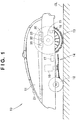
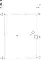
- FIG. 1 shows a robot mower capable of autonomously traveling to mow a lawn.
- the operation vehicle 10 includes a housing 11, left and right front wheels 12 provided on the front side of the housing 11, left and right rear wheels 13 provided on the rear side of the housing 11, and an operation unit 14 provided on the lower side at the center of the housing 11.
- a mowing blade is shown as an example of the operation unit 14 in the case in which the operation vehicle 10 is a robot mower.
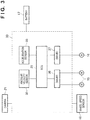
- the operation vehicle 10 includes, in the housing 11, left and right traveling motors 15 that individually drive the left and right rear wheels 13, a driving motor 16 that drives the operation unit 14, a battery 17, a wheel speed sensor 18, and a circuit board 30 on which an ECU (Electronic Control Unit) 31, an angular velocity sensor 32, and an acceleration sensor 33 are mounted.
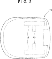
- the operation vehicle 10 also has, on the housing 11, a camera 21 capable of capturing the outside of the operation vehicle 10.
- the camera 21 includes, for example, an image sensor such as a CCD or CMOS sensor and an imaging lens configured to form an image of an object on the imaging plane of the image sensor, and can generate an image of a digital format.
- the traveling motors 15, the driving motor 16, the wheel speed sensor 18, the ECU 31, the angular velocity sensor 32, the acceleration sensor 33, and the camera 21 receive power supplied from the battery 17.
- the traveling motors 15, the driving motor 16, the wheel speed sensor 18, the angular velocity sensor 32, the acceleration sensor 33, and the camera 21 may receive power supplied from the battery 17 via the ECU 31.
- the ECU 31 receives signals (or data) from the wheel speed sensor 18, the angular velocity sensor 32, the acceleration sensor 33, and the camera 21 and controls the operations of the traveling motors 15 and the driving motor 16.
- the ECU 31 individually controls the left and right traveling motors 15, thereby controlling the movement of the operation vehicle 10.
- the left traveling motor 15 individually drives the left rear wheel 13, and the right traveling motor 15 individually drives the right rear wheel 13.
- the operation vehicle 10 travels straight forward (moves ahead).
- both the left and right traveling motors 15 rotate in the reverse direction at a uniform velocity, the operation vehicle 10 travels straight backward (moves back).
- the operation vehicle 10 turns in the direction of the motor with the lower rotation speed out of the left and right traveling motors 15. If one of the left and right traveling motors 15 rotates in the forward direction, and the other rotates in the reverse direction at the same rotation speed, the operation vehicle 10 can turn in the direction of the reversely rotating motor out of the left and right traveling motors 15 without changing the position of the operation vehicle 10.
- the circuit board 30 includes the ECU 31, the angular velocity sensor 32, the acceleration sensor 33, a driver 36 that individually controls the rotations of the left and right traveling motors 15, and a driver 37 that controls the rotation of the driving motor 16.
- the circuit board 30 is electrically connected to the camera 21, the battery 17, and the wheel speed sensor 18.
- the angular velocity sensor 32 outputs, to the ECU 31, a signal representing a yaw rate that is the turning angle velocity of the barycentric position (not shown) of the operation vehicle 10 about a vertical axis. That is, the ECU 31 receives the signal representing the yaw rate from the angular velocity sensor 32, thereby acquiring the front direction (traveling direction) of the operation vehicle 10 by a calculation or the like.
- the acceleration sensor 33 outputs, to the ECU 31, a signal representing an acceleration acting in, for example, three directions, that is, the front-and-rear direction, the left-and-right direction, and the vertical direction of the operation vehicle 10.
- the acceleration sensor 33 need not always output a signal representing the acceleration acting in the three directions, and may output a signal representing an acceleration acting in, for example, one or two of the three directions.
- the driver 36 individually controls the rotations of the left and right traveling motors 15 in accordance with a signal received from the ECU 31.
- the driver 37 controls the rotation of the driving motor 16 in accordance with a signal received from the ECU 31.
- the angular velocity sensor 32, the acceleration sensor 33, the driver 36, and the driver 37 are provided on the circuit board 30 as constituent elements separated from the ECU 31.
- the ECU 31 may include at least one of them.
- the wheel speed sensor 18 is provided in the operation vehicle 10 to be able to detect the rotation speed of the rear wheels 13, and outputs a signal representing the rotation speed of the rear wheels 13 to the circuit board 30, more specifically, the ECU 31. That is, the ECU 31 receives the signal representing the rotation speed of the rear wheels 13 from the wheel speed sensor 18, thereby acquiring the distance of the movement of the operation vehicle 10 by a calculation or the like.
- the camera 21 is provided on the operation vehicle 10 to be able to capture the outside of the operation vehicle 10, and outputs the data of a captured image to the circuit board 30, more specifically, the ECU 31.
- one camera 21 is electrically connected to the circuit board 30.
- two or more cameras 21 may be connected to the circuit board 30.
- Cameras 21 in an appropriate number may be provided at appropriate positions on the operation vehicle 10 so as to capture the whole circumference of the operation vehicle 10. For example, a total of four cameras 21 may be provided such that one camera 21 is arranged on each of the front, rear, left, and right sides of the housing 11 of the operation vehicle 10. Alternatively, for example, one camera 21 having an angle of view capable of capturing the whole circumference of the operation vehicle 10 may be provided on the upper portion of the housing 11 of the operation vehicle 10.
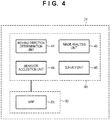
- the ECU 31 is formed from, for example, a microcomputer including a processing unit 40 such as a CPU (Central Processing Unit), and a storage unit 50 such as a RAM (Random Access Memory) and a ROM (Read Only Memory).
- the storage unit 50 stores map data (map) 51 concerning an operation area that is a range where the operation vehicle 10 performs an operation.
- the processing unit 40 for example, executes a program (not shown) stored in the storage unit 50, thereby functioning as a moving direction determination unit 41, an image analysis unit 43, a behavior acquisition unit 44, and a survey unit 45.
- a program not shown stored in the storage unit 50, thereby functioning as a moving direction determination unit 41, an image analysis unit 43, a behavior acquisition unit 44, and a survey unit 45.
- at least one of the moving direction determination unit 41, the image analysis unit 43, the behavior acquisition unit 44, or the survey unit 45 may be implemented by, for example, hardware such as an analog circuit.
- the moving direction determination unit 41 determines the direction (moving direction) to move the operation vehicle 10.
- the image analysis unit 43 receives an image obtained by capturing the outside of the operation vehicle 10 by the camera 21, and analyzes the image using, for example, known image processing and pattern matching methods. If the operation vehicle 10 includes a plurality of cameras 21, the image analysis unit 43 may analyze an image of the whole circumference of the operation vehicle 10, which is obtained by connecting captured images of the outside of the operation vehicle 10 received from the plurality of cameras 21. If the received image includes a marker (to be described later), the image analysis unit 43 extracts the marker. The image analysis unit 43 acquires the angle difference between the front direction (traveling direction) of the operation vehicle 10 and a direction indicating a marker extracted from the current position of the operation vehicle 10 by a calculation or the like.
- the behavior acquisition unit 44 acquires behavior information including the distance and direction of the movement of the operation vehicle 10.
- the behavior acquisition unit 44 acquires the distance of the movement of the operation vehicle 10 in accordance with a signal received from the wheel speed sensor 18 by a calculation or the like.
- the behavior acquisition unit 44 also acquires the direction of the movement of the operation vehicle 10 in accordance with a signal received from the angular velocity sensor 32 by a calculation or the like.
- the behavior acquisition unit 44 may further include, in the behavior information, for example, information acquired according to a signal received from the acceleration sensor 33 by a calculation or the like.
- the survey unit 45 acquires the position information of a marker extracted by the image analysis unit 43 by triangulation (to be described later) using the analysis result of the image analysis unit 43 and the behavior information obtained by the behavior acquisition unit 44.
- the survey unit 45 for example, reflects the obtained position information of the marker on the map 51.
- the operation vehicle 10 has, for example, an operation mode and a survey mode.
- the operation vehicle 10 autonomously travels in the operation area and performs an operation of, for example, mowing a lawn.
- the operation vehicle 10 acquires the position information of a marker and updates the map 51 during autonomous traveling.
- FIG. 5 shows an example in which the operation area 70 is viewed from above.
- the operation area 70 is represented by a range surrounded by a broken line.
- a station 60 capable of storing the operation vehicle 10 is illustrated. When stored in the station 60, the operation vehicle 10 can charge the battery 17. When the operation in the operation mode or the survey mode ends, the operation vehicle 10 may move to the station 60 and be stored. Note that in the example shown in Fig. 5 , the station 60 is arranged across the boundary between the inside and the outside of the operation area 70. However, the station 60 may be arranged inside the operation area 70 or outside the operation area 70.
- the operation vehicle 10 can set (or store) the operation area 70 on the map 51 stored in the storage unit 50 of the ECU 31.
- the map 51 is, for example, a two-dimensional map representing the same plane as the ground.
- Position information (two-dimensional coordinates) on the map 51 and position information (two-dimensional coordinates) on the real space have a correspondence relationship.
- the position information (two-dimensional coordinates) on the real space is represented by a coordinate plane on the same plane as the ground.
- the coordinate plane has its origin at a preset position or the position where the station 60 is arranged, and includes two coordinate axes, that is, an X-axis and a Y-axis intersecting the X-axis at a right angle. Note that in the example shown in Fig. 5 , the origin and the X- and Y-axes are not illustrated, and an example in the X-axis positive direction and the Y-axis positive direction is shown.
- the rectangular operation area 70 is shown.
- Markers 71 (71-1, 71-2, 71-3, and 71-4) exist at the four apexes of the rectangle. That is, in the example shown in Fig. 5 , the range inside a rectangle defined by four coordinate points corresponding to the positions of the four markers 71 (71-1, 71-2, 71-3, and 71-4) on the real space is set as the operation area 70 on the map 51.
- the operation vehicle 10 can acquire, by the behavior acquisition unit 44 of the ECU 31, behavior information including the distance of the movement of the operation vehicle 10 and the direction of the movement of the operation vehicle 10. For this reason, the operation vehicle 10 can grasp the current position of the operation vehicle 10 on the map 51.
- the operation vehicle 10 can travel only inside the operation area 70.
- the operation vehicle 10 can implement autonomously traveling only inside the operation area 70 and performing an operation of, for example, mowing a lawn.
- position information (two-dimensional coordinates) concerning the boundary between the inside and the outside of the operation area 70 on the real space needs to be grasped.
- the survey unit 45 acquires the position information (two-dimensional coordinates) of each marker 71 on the real space by triangulation as the position information concerning the boundary between the inside and the outside of the operation area 70.
- the user can edit the map 51.
- a position spaced apart from the position information of the marker 71 reflected on the map 51 by an arbitrary distance may be set on the boundary between the inside and the outside of the operation area 70.
- the marker 71 is an object that the image analysis unit 43 can extract from an image received from the camera 21, and may be, for example, a rod-shaped object capable of standing on the ground. A tree, a stone, or the like may be used as the marker 71 as long as the image analysis unit 43 can extract it from the image received from the camera 21.
- the marker 71 may be, for example, configured to be able to emit light in a specific frequency domain to be captured by the camera 21.
- FIG. 6 shows an example in which the operation vehicle 10 that moves in a constant direction and the marker 71 are viewed from above.
- L be the distance between a position 10-A and a position 10-B, through which the operation vehicle 10 moving in the constant direction passes.
- HA be the distance of a line that connects the position 10-A and the position of the marker 71.
- ⁇ A be the angle made by the direction of the movement of the operation vehicle 10 and the line that connects the position 10-A and the position of the marker 71.
- ⁇ B be the angle made by the direction of the movement of the operation vehicle 10 and a line that connects the position 10-B and the position of the marker 71.
- ⁇ be the angle made by the line that passes through the position 10-A and the position of the marker 71 and the line that passes through the position 10-B and the position of the marker 71.
- HA can be determined by calculating equation (2).
- the survey unit 45 can obtain L, ⁇ A, and ⁇ B as the operation vehicle 10 moves in the constant direction from the position 10-A to the position 10-B. That is, L is acquired by the behavior acquisition unit 44, and ⁇ A and ⁇ B are acquired by the image analysis unit 43.
- the survey unit 45 can acquire information representing that the marker 71 is arranged at a position spaced part from the position 10-A by HA in a direction with the angle difference ⁇ A with respect to the front direction (traveling direction) of the operation vehicle 10 at the position 10-A. In the above-described way, the survey unit 45 acquires the position information (two-dimensional coordinates) of the marker 71.
- first point corresponding to the position 10-A in Fig. 6
- second point corresponding to the position 10-B in Fig. 6
- first angle corresponding to the angle ⁇ A in Fig. 6
- second angle corresponding to the angle ⁇ B in Fig. 6
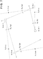
- FIG. 7 shows an example in which the operation vehicle 10 and the four markers 71 (71-1, 71-2, 71-3, and 71-4) are viewed from above.
- the operation vehicle 10 is assumed to start the survey mode at a position 10-1.
- the operation vehicle 10 that has started execution of the survey mode captures the outside of the operation vehicle 10 by the camera 21 at the position 10-1.
- the image analysis unit 43 receives the image captured by the camera 21 and analyzes it. If the marker 71-1 is included in the analyzed image, the image analysis unit 43 extracts the marker 71-1.
- the survey unit 45 starts acquiring the position information of the marker 71-1 extracted by the image analysis unit 43.
- the moving direction determination unit 41 determines the moving direction in which the operation vehicle 10 moves to acquire the position information. That is, the moving direction determination unit 41 determines, as the moving direction of the operation vehicle 10, a direction in which the operation vehicle 10 does not come into contact with the marker 71 (marker 71-1), and an angle difference ⁇ g ( ⁇ g1) with respect to the direction from the current position (position 10-1) of the operation vehicle 10 to the marker 71 (marker 71-1) is smaller than 90°.
- the operation vehicle 10 When the moving direction determination unit 41 determines the moving direction of the operation vehicle 10, the operation vehicle 10 turns until the front direction (traveling direction) matches the moving direction determined by the moving direction determination unit 41. After the front direction (traveling direction) matches the moving direction determined by the moving direction determination unit 41, the operation vehicle 10 moves (moves ahead) in the front direction (traveling direction). During the movement of the operation vehicle 10, the survey unit 45 acquires the position information of the marker 71 (marker 71-1) by the above-described triangulation.
- the moving direction determination unit 41 determines the moving direction of the operation vehicle 10. This makes it possible to acquire the position information of the marker 71 without causing the user to acquire the position information of the marker 71 by himself/herself and guide the moving direction of the operation vehicle 10.
- the moving direction determined by the moving direction determination unit 41 is a direction in which the operation vehicle 10 does not come into contact with the marker 71, and the angle difference ⁇ g with respect to the direction from the current position of the operation vehicle 10 to the marker 71 is smaller than 90°, a timing is generated at which the distance between the operation vehicle 10 and the marker 71 shortens during the movement of the operation vehicle 10 in the determined moving direction.
- the position information of the marker 71 can be acquired based on an image captured when the distance to the marker 71 is short.
- the moving direction determined by the moving direction determination unit 41 may be a direction in which the operation vehicle 10 does not come into contact with the marker 71, and the angle difference ⁇ g with respect to the direction from the current position of the operation vehicle 10 to the marker 71 is smaller than 45°. In this case, the timing at which the distance between the operation vehicle 10 and the marker 71 shortens is sufficiently generated during the movement of the operation vehicle 10 in the determined moving direction.
- the survey unit 45 may determine whether acquisition of the position information of the marker 71 (marker 71-1) extracted by the image analysis unit 43 is completed. Upon determining that acquisition of the position information of the marker 71 (marker 71-1) is not completed, the survey unit 45 may start acquiring the position information of the marker 71 (marker 71-1). For example, the survey unit 45 may refer to the map 51 and determine the marker 71 with stored position information as the marker 71 for which the position information acquisition is completed. Alternatively, the survey unit 45 may determine the marker 71 for which the position information acquisition was executed a predetermined number of times as the marker 71 for which the position information acquisition is completed.
- the survey unit 45 When the survey unit 45 starts acquiring the position information of the marker 71 for which the position information acquisition is not completed, the position information acquisition can be prevented from being executed again for the marker 71 for which the position information acquisition is already completed. As a result, for example, the power consumption of the battery 17 for the operation in the survey mode can be reduced.
- the image analysis unit 43 extracts all the markers 71.
- the survey unit 45 determines whether the plurality of markers 71 extracted by the image analysis unit 43 include the marker 71 for which the position information acquisition is not completed. If the marker 71 for which the position information acquisition is not completed is included, the survey unit 45 starts acquiring the position information of the marker 71 of the highest visibility from the current position of the operation vehicle 10 out of the markers 71 for which the position information acquisition is not completed.
- the marker 71 of the highest visibility from the current position of the operation vehicle 10 may be, for example, the marker 71 whose size on the received image is largest. For example, the same procedure as described above is repeated until the marker 71 for which the position information acquisition is not completed is not included any more in the image captured by the camera 21 at the position where the acquisition of the position information of the marker 71 is completed.
- an image captured by the camera 21 when the operation vehicle 10 is located at the position 10-1 includes the four markers 71 (71-1, 71-2, 71-3, and 71-4) for which the position information acquisition is not completed.
- the image analysis unit 43 extracts the four markers 71 (71-1, 71-2, 71-3, and 71-4) included in the received image, and the survey unit 45 determines that the acquisition of the position information of the four markers 71 (71-1, 71-2, 71-3, and 71-4) is not completed.
- the survey unit 45 starts acquiring the position information of the marker 71-1 of the highest visibility from the current position (position 10-1) of the operation vehicle 10 out of the four markers 71 (71-1, 71-2, 71-3, and 71-4) for which the position information acquisition is not completed. Then, the moving direction determination unit 41 determines the moving direction of the operation vehicle 10. While the operation vehicle 10 is moving in the determined moving direction, the survey unit 45 acquires the position information of the marker 71-1.
- an image captured by the camera 21 at a position (for example, a position 10-2) where the acquisition of the position information of the marker 71-1 is completed includes the four markers 71 (71-1, 71-2, 71-3, and 71-4).
- the image analysis unit 43 extracts the four markers 71 (71-1, 71-2, 71-3, and 71-4) included in the received image, and the survey unit 45 determines that the acquisition of the position information of the three markers 71 (71-2, 71-3, and 71-4) is not completed.
- the survey unit 45 starts acquiring the position information of the marker 71-2 of the highest visibility from the current position (position 10-2) of the operation vehicle 10 out of the three markers 71 (71-2, 71-3, and 71-4) for which the position information acquisition is not completed.
- a position for example, a position 10-3 where the acquisition of the position information of the marker 71-2 is completed
- acquisition of the position information of the marker 71-3 is started in accordance with the same procedure as described above.
- a position for example, a position 10-4 where the acquisition of the position information of the marker 71-3 is completed
- acquisition of the position information of the marker 71-4 is started in accordance with the same procedure as described above.
- the moving direction determined by the moving direction determination unit 41 is a direction in which the operation vehicle 10 does not come into contact with the marker 71, and the angle difference ⁇ g ( ⁇ g1, ⁇ g2, ⁇ g3, or ⁇ g4) with respect to the direction from the current position of the operation vehicle 10 to the marker 71 is smaller than 90°.
- the operation vehicle 10 may end the operation in the survey mode. However, alternatively, for example, if the acquisition of the position information of all markers 71 is completed three times, the operation vehicle 10 may end the operation in the survey mode.
- the survey unit 45 determines the marker 71 whose position information is to be acquired. Hence, the user need not determine the marker 71 whose position information is to be acquired. In addition, the survey unit 45 starts acquiring the position information of the marker 71 of the highest visibility from the current position of the operation vehicle 10 out of the markers 71 for which the position information acquisition is not completed. For example, as compared to a case in which the acquisition of the position information of the marker 71 farthest from the current position of the operation vehicle 10 is started, the moving distance needed until the position information acquisition is completed for all markers 71 is shortened. As a result, the power consumption of the battery 17 for the operation in the survey mode can be reduced.
- step S101 the camera 21 of the operation vehicle 10 captures the outside of the operation vehicle 10.
- step S102 the image analysis unit 43 analyzes the image captured by the camera 21 and extracts the markers 71 included in the image.
- step S103 the survey unit 45 determines whether the markers 71 extracted by the image analysis unit 43 include the marker 71 for which the position information acquisition is not completed.
- step S104 the survey unit 45 determines the marker 71 whose position information is to be acquired, and the moving direction determination unit 41 determines the moving direction of the operation vehicle 10.
- step S105 the operation vehicle 10 starts moving in the moving direction determined by the moving direction determination unit 41, and during the movement of the operation vehicle 10 in the moving direction, the survey unit 45 acquires the position information of the marker 71 by the above-described triangulation.
- step S106 the survey unit 45 reflects the acquired position information of the marker 71 on the map 51 and updates the map 51.
- the process returns to step S101. That is, the processes of steps S101 to S106 are repeated until it is determined in step S103 that the markers 71 extracted by the image analysis unit 43 do not include the marker 71 for which the position information acquisition is not completed.
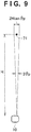
- Fig. 9 shows an example in which the operation vehicle 10 and the marker 71 are viewed from above. In the example shown in Fig. 9 , the operation vehicle 10 and the marker 71 are spaced apart by a distance H.
- an error occurs because of the resolution of the image sensor, the focal length of the imaging lens, and the like.
- an imaging error ⁇ p (the range of the imaging error is 2 ⁇ p) of a predetermined angle occurs when the camera 21 captures an image.
- the imaging error ⁇ p occurs, the marker 71 spaced apart from the operation vehicle 10 by the distance H is captured while including an error in the range of 2Htan ⁇ p on the real space. That is, the influence of the imaging error becomes large as the distance between the camera 21 and the marker 71 increases.
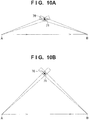
- a region 76 shown in Figs. 10A and 10B represents the range of an error in acquiring the position information of the marker 71 using triangulation.
- the region 76 is a region formed by the overlap of an imaging error generated when capturing the marker 71 at a position A that is an example of the first point and an imaging error generated when capturing the marker 71 at a position B that is an example of the second point.
- the distance from the position A (first point) to the marker 71 and the distance from the position B (second point) to the marker 71 almost equal.
- the region 76 is smaller in Fig. 10B in which the angle made by the position A (first point), the marker 71, and the position B (second point) is close to 90° than in Fig. 10A .
- the angle made by the position A (first point), the marker 71, and the position B (second point) is the same as the angle difference between the first angle and the second angle.
- the accuracy of the acquisition of the position information of the marker 71 improves as the angle difference between the first angle and the second angle used in the triangulation becomes close to 90°. That is, the survey unit 45 determines the first point and/or the second point during the movement of the operation vehicle 10 in the moving direction such that the angle difference between the first angle and the second angle becomes close to 90°, thereby reducing the imaging error. As a result, the user need not determine the first point and the second point to guarantee the accuracy of the acquisition of the position information of the marker 71.
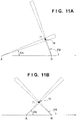
- Figs. 11A and 11B show two examples representing the accuracy of the acquisition of the position information of the marker 71 using triangulation in a case in which the angle difference between the first angle and the second angle is about 90°.
- the region 76 in Fig. 11A is larger than the region 76 in Fig. 11B . This is because the distance from the position A (first point) to the marker 71 in Fig. 11A is longer than the distance from the position A (first point) to the marker 71 in Fig. 11B , and therefore, the imaging error has a large influence.
- both the distance between the first point and the marker 71 and the distance between the second point and the marker 71 are shortest under the condition that the first angle ⁇ A of about 45° and the second angle ⁇ B of about 135° hold, as shown in Fig. 11B . That is, during the movement of the operation vehicle 10 in the moving direction, the survey unit 45 determines the first point such that the first angle becomes close to 45° and also determines the second point such that the second angle becomes close to 135°, thereby improving the accuracy of the acquisition of the position information of the marker 71.
- the moving direction determined by the moving direction determination unit 41 when the survey unit 45 starts acquiring the position information of the marker 71 may be a direction in which the operation vehicle 10 does not come into contact with the marker 71, and the angle difference ⁇ g with respect to the direction from the current position of the operation vehicle 10 to the marker 71 is smaller than 45°. That is, if the moving direction of the operation vehicle 10 is a direction in which the angle difference ⁇ g with respect to the direction from the current position of the operation vehicle 10 to the marker 71 is smaller than 45°, during the movement, the operation vehicle 10 always passes through the first point at which the first angle is 45°.
- FIG. 12 shows an example of a detailed process of step S105 in the flowchart of Fig. 8 .
- step S201 the survey unit 45 determines whether a marker detection flag is ON. If YES in step S201, the process advances to step S205. If NO in step S201, the process advances to step S202. Note that immediately after the process advances from step S104 to step S105 in the flowchart of Fig. 8 , the marker detection flag is OFF.
- step S202 the survey unit 45 determines whether an image captured by the camera 21 at the current position includes the marker 71. If YES in step S202, the process advances to step S203. If NO in step S202, the process returns to START.
- step S203 the survey unit 45 stores, as the first angle, the angle difference between the moving direction of the operation vehicle 10 at the position where the image determined in step S202 was captured and the direction from the operation vehicle 10 to the marker 71.
- the angle difference between the moving direction of the operation vehicle 10 at the position where the image was captured and the direction from the operation vehicle 10 to the marker 71 will also be referred to as a marker detection angle hereinafter.
- the survey unit 45 receives the marker detection angle from, for example, the image analysis unit 43.
- step S203 the survey unit 45 also stores the position where the image determined in step S202 was captured as the first point. The position where the image was captured will also be referred to as a marker detection position hereinafter.
- the survey unit 45 receives the marker detection position from, for example, the behavior acquisition unit 44.
- step S204 the survey unit 45 turns on the marker detection flag.
- step S205 the survey unit 45 determines whether the first angle is determined. If YES in step S205, the process advances to step S211. If NO in step S205, the process advances to step S206.
- step S206 the survey unit 45 determines whether an image captured by the camera 21 at the current position includes the marker 71. If YES in step S206, the process advances to step S207. If NO in step S206, the procedure ends. Note that if step S206 ends with NO, and the procedure ends, a situation in which the marker 71 that should be detectable cannot be detected due to some reason (the image analysis unit 43 cannot extract the marker 71) has occurred. Hence, the process returns to, for example, step S101 in the flowchart of Fig. 8 .
- step S207 the survey unit 45 determines whether the marker detection angle at the position where the image determined in step S206 was captured is closer to 45° than the first angle. If YES in step S207, the process advances to step S208. If NO in step S207, the process advances to step S209.
- step S208 the survey unit 45 stores (overwrites) the marker detection angle at the position where the image determined in step S206 was captured newly as the first angle in place of the currently stored first angle. In step S208, the survey unit 45 also stores (overwrites) the position where the image determined in step S206 was captured newly as the first point in place of the currently stored first point.
- step S209 the survey unit 45 determines the currently stored first angle and the currently stored first point as the first angle and the first point to be used in triangulation.
- step S210 the survey unit 45 stores the marker detection angle at the position where the image determined in step S206 was captured as the second angle, and stores the position where the image was captured as the second point.
- the survey unit 45 can determine the first point during the movement of the operation vehicle 10 in the moving direction such that the first angle becomes close to 45°. As a result, the accuracy of the acquisition of the position information of the marker 71 improves.
- step S211 the survey unit 45 determines whether an image captured by the camera 21 at the current position includes the marker 71. If YES in step S211, the process advances to step S212. If NO in step S211, the process advances to step S214.
- step S212 the survey unit 45 determines whether the angle difference between the determined first angle and the marker detection angle at the position where the image determined in step S211 was captured is closer to 90° than the angle difference between the determined first angle and the currently stored second angle. If YES in step S212, the process advances to step S213. If NO in step S212, the process advances to step S214. In step S213, the survey unit 45 stores the marker detection angle at the position where the image determined in step S211 was captured newly as the second angle in place of the currently stored second angle. In step S213, the survey unit 45 also stores the position where the image determined in step S211 was captured newly as the second point in place of the currently stored second point. When the process of step S213 ends, the process returns to START.
- step S214 the survey unit 45 determines the currently stored second angle and the currently stored second point as the second angle and the second point to be used in triangulation.
- step S215 the survey unit 45 calculates and acquires the position information of the marker 71 by triangulation using the determined first angle, the determined second angle, and the distance between the determined first point and the determined second point.
- the procedure ends. That is, when the process of step S215 ends, the process advances to step S106 in the flowchart of Fig. 8 .
- the survey unit 45 can determine the second point during the movement of the operation vehicle 10 in the moving direction such that the second angle becomes close to 135°. As a result, the accuracy of the acquisition of the position information of the marker 71 improves.
- the flowchart of Fig. 12 is merely an example, and the survey unit 45 need not execute the processes of all steps.
- the survey unit 45 may execute, for example, processing for determining the first point, that is, processing corresponding to steps S201 to S209 in the flowchart of Fig. 12 .
- the survey unit 45 may execute, for example, processing for determining the second point, that is, processing corresponding to steps S211 to S215 in the flowchart of Fig. 12 .
- the lost can occur when, for example, a tree, a rock, or the like whose position is fixed or a human, an animal, or the like whose position is not fixed stands as an obstacle 78 between the camera 21 and the marker 71.
- the lost can also occur due to, for example, backlight.
- Fig. 13 shows an example in which the operation vehicle 10 that moves in a predetermined moving direction and the marker 71 are viewed from above.
- Fig. 13 also shows the obstacle 78.
- the operation vehicle 10 and the marker 71 can be connected by a line from positions 10-A, 10-B, 10-E, and 10-F without an interference with the obstacle 78.
- the operation vehicle 10 and the marker 71 cannot be connected by a line from positions 10-C and 10-D without an interference with the obstacle 78.
- the image analysis unit 43 is assumed to recognize the marker 71 extracted before the occurrence of the lost and the marker 71 extracted after the lost is eliminated as different markers 71. For example, if such a lost occurs during the time when the operation vehicle 10 moves to cause the survey unit 45 to acquire the position information of the marker 71, the survey unit 45 is assumed to be unable to accurately acquire the position information of the marker 71 or unable to acquire the position information of the marker 71.
- information used by the survey unit 45 to acquire the position information of the marker 71 is limited to one of information (the marker detection angle and the marker detection position) obtained before the operation vehicle 10 reaches the position 10-C (before the occurrence of the lost) and information (the marker detection angle and the marker detection position) obtained after the operation vehicle 10 reaches the position 10-E (after the elimination of the lost).
- step S211 ends with NO
- step S206 ends with NO.
- the second angle and the second point stored during the time when the operation vehicle 10 moves to the position 10-C are determined as the second angle and the second point to be used in triangulation (step S214), and the position information of the marker 71 is obtained by triangulation using them together with the already determined first angle and first point (step S215). In this case, there is a possibility that the position information of the marker 71 cannot accurately be acquired.
- step S206 ends with NO, the procedure ends without acquiring the position information of the marker 71.
- the image analysis unit 43 can extract the marker 71 from a captured image again. Hence, the image analysis unit 43 may determine whether the marker 71 extracted before the occurrence of the lost and the marker 71 extracted after the elimination of the lost are the same marker 71. If the marker 71 extracted by the image analysis unit 43 before the occurrence of the lost and the marker 71 extracted after the elimination of the lost are the same marker 71, the survey unit 45 may acquire the position information of the marker 71 using both the information (the marker detection angle and the marker detection position) obtained before the occurrence of the lost and the information (the marker detection angle and the marker detection position) obtained after the elimination of the lost.
- the position information of the marker 71 can accurately be acquired.
- the user need not guide the operation vehicle 10 up to a position without an influence of the obstacle 78.
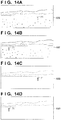
- FIG. 14A shows an image 80B captured at the position 10-B in the example of Fig. 13 .
- Fig. 14B shows an image 80E captured at the position 10-E in the example of Fig. 13 .
- Fig. 14C shows a processed image 80Bi as an example of an image for which the image analysis unit 43 has performed image processing of removing elements other than the marker 71 from the image 80B.
- Fig. 14D shows a processed image 80Ei as an example of an image for which the image analysis unit 43 has performed image processing of removing elements other than the marker 71 from the image 80E. Note that Figs. 14A to 14D do not illustrate the obstacle 78.
- the image analysis unit 43 may compare the shape feature of the landscape near the marker 71 on the image 80B with the shape feature of the landscape near the marker 71 on the image 80E. The image analysis unit 43 may determine based on the comparison result whether the marker 71 included in the image 80B and the marker 71 included in the image 80E are the same marker 71. According to this example of the method, the shape feature of the landscape near the marker 71 can be used for the determination. This is effective when, for example, a characteristic object (for example, a tree) is included in the landscape near the marker 71.
- a characteristic object for example, a tree
- This method also provides the effect of guaranteeing the accuracy of determination even in a case in which it is difficult to determine the matching using only the shape feature of the marker 71, for example, in a case in which an image captured after the elimination of the lost includes a plurality of markers 71 having the same shape.
- the image analysis unit 43 may predict a position where the marker 71 included in the image 80B is included in the image 80E using the distance between the position 10-B in the example of Fig. 13 and the position 10-E in the example of Fig. 13 and compare the predicted position of the marker 71 on the image 80E with the actual position of the marker 71 on the image 80E.
- the image analysis unit 43 may determine based on the comparison result whether the marker 71 included in the image 80B and the marker 71 included in the image 80E are the same marker 71. According to this example of the method, the distance of the movement of the operation vehicle 10 can be used for the determination.
- This method provides the effect of guaranteeing the accuracy of determination even in a case in which it is difficult to determine the matching using only the shape feature of the marker 71, for example, in a case in which an image captured after the elimination of the lost includes a plurality of markers 71 having the same shape.
- the image analysis unit 43 may compare the shape feature of the marker 71 on the processed image 80Bi with the shape feature of the marker 71 on the processed image 80Ei. The image analysis unit 43 may determine based on the comparison result whether the marker 71 included in the image 80B and the marker 71 included in the image 80E are the same marker 71. According to this example of the method, the shape feature of the marker 71 can be used for the determination. This is particularly effective when, for example, the marker 71 has a characteristic shape.
- the image analysis unit 43 may predict a position where the marker 71 included in the processed image 80Bi is included in the processed image 80Ei using the distance between the position 10-B in the example of Fig. 13 and the position 10-E in the example of Fig. 13 and compare the predicted position of the marker 71 on the processed image 80Ei with the actual position of the marker 71 on the processed image 80Ei.
- the image analysis unit 43 may determine based on the comparison result whether the marker 71 included in the image 80B and the marker 71 included in the image 80E are the same marker 71. According to this example of the method, the distance of the movement of the operation vehicle 10 can be used for the determination.
- This method provides the effect of guaranteeing the accuracy of determination even in a case in which it is difficult to determine the matching using only the shape feature of the marker 71, for example, in a case in which an image captured after the elimination of the lost includes a plurality of markers 71 having the same shape.
- the image analysis unit 43 may make a determination using a result obtained by solely executing one of the methods, or may make a general determination using a result obtained by executing two or more of the methods.
- the image analysis unit 43 may execute a method other than those described above and make a general determination in consideration of the result as well.
- the operation vehicle 10 may execute part of the examples of the operation described above.
- a first aspect according to the present invention is directed to an automatic operation vehicle that automatically performs an operation in an operation area, comprising:
- the situation in which the marker that could be extracted from the image captured by the camera cannot be extracted by the image analysis unit from the image captured by the camera is also called a lost.
- the lost can occur when, for example, an obstacle stands between the camera and the marker. If the image analysis unit cannot determine whether the marker extracted before the occurrence of the lost and the marker extracted after the elimination of the lost are the same marker, for example, the automatic operation vehicle is assumed to recognize the markers extracted by the image analysis unit before and after the occurrence of the lost as different markers. For example, if the lost occurs during the time when the automatic operation vehicle is acquiring the position information of the marker by triangulation, accurate acquisition of the position information of the marker or acquisition of the position information of the marker is assumed to be impossible.
- the image analysis unit determines whether the marker extracted before the occurrence of the lost and the marker extracted after the elimination of the lost are the same marker, the user need not guide the automatic operation vehicle up to a position without an influence of an obstacle during the movement of the automatic operation vehicle.
- the image analysis unit may determine whether the marker extracted before the occurrence of the situation and the marker extracted after the elimination of the situation are the same marker.
- the shape feature of the marker can be used for the determination.
- the image analysis unit may determine whether the marker extracted before the occurrence of the situation and the marker extracted after the elimination of the situation are the same marker.
- the shape feature of the landscape near the marker can be used for the determination.
- the image analysis unit may determine whether the marker extracted before the occurrence of the situation and the marker extracted after the elimination of the situation are the same marker.
- the distance of the movement of the automatic operation vehicle can be used for the determination.
Landscapes
- Engineering & Computer Science (AREA)
- Physics & Mathematics (AREA)
- General Physics & Mathematics (AREA)
- Automation & Control Theory (AREA)
- Radar, Positioning & Navigation (AREA)
- Remote Sensing (AREA)
- Aviation & Aerospace Engineering (AREA)
- Computer Vision & Pattern Recognition (AREA)
- Theoretical Computer Science (AREA)
- Life Sciences & Earth Sciences (AREA)
- Electromagnetism (AREA)
- Environmental Sciences (AREA)
- Multimedia (AREA)
- Data Mining & Analysis (AREA)
- Transportation (AREA)
- Evolutionary Computation (AREA)
- Mechanical Engineering (AREA)
- Artificial Intelligence (AREA)
- Evolutionary Biology (AREA)
- Bioinformatics & Computational Biology (AREA)
- Bioinformatics & Cheminformatics (AREA)
- General Engineering & Computer Science (AREA)
- Control Of Position, Course, Altitude, Or Attitude Of Moving Bodies (AREA)
- Guiding Agricultural Machines (AREA)
- Game Theory and Decision Science (AREA)
- Medical Informatics (AREA)
- Health & Medical Sciences (AREA)
- Business, Economics & Management (AREA)
- Traffic Control Systems (AREA)
- Image Processing (AREA)
- Image Analysis (AREA)
- Length Measuring Devices By Optical Means (AREA)
Claims (5)
- Automatischer Mäher (10), der automatisch einen Betrieb in einem Arbeitsbereich (70) ausführt, wobei das Fahrzeug umfasst:eine Bildanalyseeinrichtung (43), die konfiguriert ist, um eine Markierung (71) zu extrahieren, die in einem Bild enthalten ist, das von einer Kamera (21) aufgenommen wurde, die an dem automatischen Mäher (10) vorgesehen ist, und
dadurch gekennzeichnet, dasswenn eine Situation, in der die Markierung (71), die aus dem von der Kamera (21) aufgenommenen Bild extrahiert wurde, nicht durch das Bildanalysemittel (43) aus dem von der Kamera (43) aufgenommenen Bild extrahiert werden kann, während einer Bewegung des automatischen Mähers (10) in eine konstante Richtung aufgetreten ist, dann durch Verwendung eines Ergebnisses, das durch Vergleichen eines Formmerkmals einer Landschaft in der Nähe der Markierung (71) erhalten wurde, die in dem von der Kamera (21) aufgenommenen Bild vor dem Auftreten der Situation mit dem Formmerkmal einer Landschaft in der Nähe der Markierung (71) erhalten wurde, die in dem von der Kamera (21) aufgenommenen Bild nach Beseitigung der Situation enthalten ist,das Bildanalysemittel (43) bestimmt, ob die vor einem Auftreten der Situation extrahierte Markierung (71) und die nach einer Beseitigung der Situation extrahierte Markierung (71) die gleiche Markierung (71) sind. - Fahrzeug nach Anspruch 1, wobei ein Ergebnis verwendet wird, das durch Vergleichen eines Formmerkmals der Markierung (71), die in dem von der Kamera (21) vor dem Auftreten der Situation aufgenommenen Bild enthalten ist, mit einem Formmerkmal der Markierung (71) erhalten wird, das in dem von der Kamera (21) nach der Beseitigung der Situation aufgenommenen Bild enthalten ist,
das Bildanalysemittel bestimmt, ob die vor dem Auftreten der Situation extrahierte Markierung (71) und die nach der Beseitigung der Situation extrahierte Markierung (71) die gleiche Markierung (71) sind. - Fahrzeug nach Anspruch 1 oder 2, wobei unter Verwendung eines Ergebnisses, das durch Vorhersagen erhalten wurde, unter Verwendung eines Abstands von einer Position, in der die Kamera (21) vor dem Auftreten der Situation ein erstes Bild mit der Markierung (71) aufnimmt, zu einer Position, in der die Kamera (21) nach der Beseitigung der Situation ein zweites Bild mit der Markierung aufnimmt, einer Position, in der die im ersten Bild enthaltene Markierung (71) in einem zweiten Bild enthalten ist, und Vergleichen der vorhergesagten Position, in der die Markierung (71) enthalten ist, mit einer Position, in der die Markierung (71) tatsächlich in dem zweiten Bild enthalten ist,
das Bildanalysemittel (43) bestimmt, ob die vor dem Auftreten der Situation extrahierte Markierung (71) und die nach der Beseitigung der Situation extrahierte Markierung (71) die gleiche Markierung (71) sind. - Verfahren zum Steuern eines automatischen Mähers (10), der automatisch einen Betrieb in einem Arbeitsbereich (70) ausführt, wobei das Verfahren umfasst:Extrahieren einer Markierung (71), die in einem Bild enthalten ist, das von einer Kamera (21) aufgenommen wurde, die an dem automatischen Mäher (10) vorgesehen ist; und
dadurch gekennzeichnet, dass das Verfahren ferner umfasstwenn eine Situation, in der die Markierung (71), die aus dem von der Kamera (21) aufgenommenen Bild extrahiert wurde, nicht aus dem von der Kamera (21) aufgenommenen Bild extrahiert werden kann, während einer Bewegung des automatischen Mähers (10) in einer konstanten Richtung aufgetreten ist, dann durch Verwendung eines Ergebnisses, das durch Vergleichen eines Formmerkmals einer Landschaft in der Nähe der Markierung (71) erhalten wurde, die in dem von der Kamera (21) aufgenommenen Bild vor dem Auftreten der Situation mit dem Formmerkmal einer Landschaft in der Nähe der Markierung (71) erhalten wurde, die in dem von der Kamera (21) aufgenommenen Bild nach Beseitigung der Situation enthalten ist,Bestimmen, ob die vor einem Auftreten der Situation extrahierte Markierung (71) und die nach einer Beseitigung der Situation extrahierte Markierung (71) die gleiche Markierung (71) sind. - Programm, das einen automatischen Mäher (10), der automatisch einen Betrieb in einem Arbeitsbereich (70) ausführt, veranlasst, einen Prozess auszuführen, wobei der Prozess umfasst:Extrahieren einer Markierung (71), die in einem Bild enthalten ist, das von einer Kamera (21) aufgenommen wurde, die an dem automatischen Mäher (10) vorgesehen ist; und
dadurch gekennzeichnet, dass das Programm ferner umfasstwenn eine Situation, in der die Markierung (71), die aus dem von der Kamera (21) aufgenommenen Bild extrahiert wurde, nicht aus dem von der Kamera (21) aufgenommenen Bild extrahiert werden kann, während einer Bewegung des automatischen Mähers (10) in einer konstanten Richtung aufgetreten ist, dann durch Verwendung eines Ergebnisses, das durch Vergleichen eines Formmerkmals einer Landschaft in der Nähe der Markierung (71) erhalten wurde, die in dem von der Kamera (21) aufgenommenen Bild vor dem Auftreten der Situation mit dem Formmerkmal einer Landschaft in der Nähe der Markierung (71) erhalten wurde, die in dem von der Kamera (21) aufgenommenen Bild nach Beseitigung der Situation enthalten ist,Bestimmen, ob die vor einem Auftreten der Situation extrahierte Markierung (71) und die nach einer Beseitigung der Situation extrahierte Markierung (71) die gleiche Markierung (71) sind.
Applications Claiming Priority (1)
| Application Number | Priority Date | Filing Date | Title |
|---|---|---|---|
| JP2016055548A JP6280147B2 (ja) | 2016-03-18 | 2016-03-18 | 無人走行作業車 |
Publications (2)
| Publication Number | Publication Date |
|---|---|
| EP3226207A1 EP3226207A1 (de) | 2017-10-04 |
| EP3226207B1 true EP3226207B1 (de) | 2019-07-17 |
Family
ID=58461056
Family Applications (1)
| Application Number | Title | Priority Date | Filing Date |
|---|---|---|---|
| EP17160833.4A Active EP3226207B1 (de) | 2016-03-18 | 2017-03-14 | Fahrzeug mit automatischem betrieb |
Country Status (4)
| Country | Link |
|---|---|
| US (1) | US10068141B2 (de) |
| EP (1) | EP3226207B1 (de) |
| JP (1) | JP6280147B2 (de) |
| CN (1) | CN107203208B (de) |
Families Citing this family (10)
| Publication number | Priority date | Publication date | Assignee | Title |
|---|---|---|---|---|
| EP3315949B1 (de) * | 2015-06-23 | 2021-04-28 | Nec Corporation | Detektionssystem, detektionsverfahren und programm |
| CN109640618B (zh) * | 2016-06-24 | 2022-10-11 | Mtd产品公司 | 高效切割系统 |
| US10720125B2 (en) * | 2017-07-24 | 2020-07-21 | Intel Corporation | Method and system of wireless data transmission for virtual or augmented reality head mounted displays |
| EP3669629A4 (de) * | 2017-08-18 | 2021-05-19 | Suzhou Cleva Precision Machinery & Technology Co., Ltd. | Intelligenter mäher |
| KR101984926B1 (ko) | 2018-01-19 | 2019-05-31 | 엘지전자 주식회사 | 잔디깎기 로봇 |
| CN109254581B (zh) * | 2018-08-10 | 2021-07-02 | 合肥哈工库讯智能科技有限公司 | 一种基于运行状态分析的agv小车智能化运行调控系统 |
| WO2020105125A1 (ja) * | 2018-11-20 | 2020-05-28 | 本田技研工業株式会社 | 自律作業機、自律作業機の制御方法及びプログラム |
| JPWO2020105124A1 (ja) * | 2018-11-20 | 2021-10-28 | 本田技研工業株式会社 | 自律作業機、自律作業機の制御方法及びプログラム |
| EP3874924B1 (de) * | 2018-11-20 | 2023-08-09 | Honda Motor Co., Ltd. | Autonome arbeitsmaschine, steuerungsverfahren für autonome arbeitsmaschinen und programm |
| JP7303905B2 (ja) | 2019-12-20 | 2023-07-05 | 本田技研工業株式会社 | 作業機および処理装置 |
Family Cites Families (11)
| Publication number | Priority date | Publication date | Assignee | Title |
|---|---|---|---|---|
| KR100483548B1 (ko) * | 2002-07-26 | 2005-04-15 | 삼성광주전자 주식회사 | 로봇 청소기와 그 시스템 및 제어 방법 |
| JP4189377B2 (ja) * | 2004-12-24 | 2008-12-03 | 株式会社東芝 | 移動ロボット、移動ロボットの移動方法および移動プログラム |
| JP2010238008A (ja) * | 2009-03-31 | 2010-10-21 | Fujitsu Ltd | 映像特徴抽出装置、及びプログラム |
| US8849036B2 (en) * | 2009-10-30 | 2014-09-30 | Yujin Robot Co., Ltd. | Map generating and updating method for mobile robot position recognition |
| KR101677634B1 (ko) * | 2010-07-12 | 2016-11-18 | 엘지전자 주식회사 | 로봇 청소기 및 이의 제어 방법 |
| KR101311100B1 (ko) * | 2011-08-27 | 2013-09-25 | 고려대학교 산학협력단 | 천장 임의 형상 특성 활용 이동 로봇 위치 인식 방법 |
| CN103680291B (zh) * | 2012-09-09 | 2016-12-21 | 复旦大学 | 基于天花板视觉的同步定位与地图绘制的方法 |
| JP2014112055A (ja) * | 2012-12-05 | 2014-06-19 | Denso It Laboratory Inc | カメラ姿勢の推定方法およびカメラ姿勢の推定システム |
| US9354070B2 (en) * | 2013-10-31 | 2016-05-31 | Crown Equipment Corporation | Systems, methods, and industrial vehicles for determining the visibility of features |
| US9554508B2 (en) | 2014-03-31 | 2017-01-31 | Irobot Corporation | Autonomous mobile robot |
| JP2015225450A (ja) * | 2014-05-27 | 2015-12-14 | 村田機械株式会社 | 自律走行車、及び自律走行車における物体認識方法 |
-
2016
- 2016-03-18 JP JP2016055548A patent/JP6280147B2/ja not_active Expired - Fee Related
-
2017
- 2017-03-14 EP EP17160833.4A patent/EP3226207B1/de active Active
- 2017-03-16 US US15/460,774 patent/US10068141B2/en active Active
- 2017-03-16 CN CN201710157130.XA patent/CN107203208B/zh not_active Expired - Fee Related
Non-Patent Citations (1)
| Title |
|---|
| None * |
Also Published As
| Publication number | Publication date |
|---|---|
| EP3226207A1 (de) | 2017-10-04 |
| CN107203208A (zh) | 2017-09-26 |
| JP2017173875A (ja) | 2017-09-28 |
| US10068141B2 (en) | 2018-09-04 |
| CN107203208B (zh) | 2020-07-28 |
| US20170270369A1 (en) | 2017-09-21 |
| JP6280147B2 (ja) | 2018-02-14 |
Similar Documents
| Publication | Publication Date | Title |
|---|---|---|
| EP3226207B1 (de) | Fahrzeug mit automatischem betrieb | |
| EP3223101B1 (de) | Fahrzeug mit automatischem betrieb | |
| US11320833B2 (en) | Data processing method, apparatus and terminal | |
| US11351986B2 (en) | In-vehicle processing apparatus | |
| CN106104203B (zh) | 一种移动物体的距离检测方法、装置及飞行器 | |
| EP3223102B1 (de) | Fahrzeug mit automatischem betrieb | |
| EP3346237B1 (de) | Informationsverarbeitungsvorrichtung, informationsverarbeitungsverfahren und computerlesbares medium zur hinderniserkennung | |
| WO2022111017A1 (zh) | 一种基于 tof 摄像头的障碍物分类避障控制方法 | |
| CN112363513B (zh) | 一种基于深度信息的障碍物分类避障控制方法 | |
| KR102056147B1 (ko) | 자율주행차량을 위한 거리 데이터와 3차원 스캔 데이터의 정합 방법 및 그 장치 | |
| CN108481327B (zh) | 一种增强视觉的定位装置、定位方法及机器人 | |
| CN111213153A (zh) | 目标物体运动状态检测方法、设备及存储介质 | |
| KR20180094055A (ko) | 주차 지원 방법 및 장치 | |
| WO2004081683A1 (ja) | 自律移動ロボット | |
| WO2013145025A1 (ja) | ステレオカメラシステム及び移動体 | |
| JP4116116B2 (ja) | 移動体の測距原点認識装置 | |
| CN111897337B (zh) | 一种机器人沿边行走时的避障控制方法及其控制系统 | |
| JP7552608B2 (ja) | 情報処理装置、情報処理方法、及びプログラム | |
| EP4478298A1 (de) | Objektpositionserkennungsvorrichtung | |
| EP4718197A1 (de) | System und verfahren zur steuerung eines mobilen roboters, mobiler roboter und programm | |
| JP2002269570A (ja) | 周辺認識装置 | |
| JP2026062057A (ja) | 情報処理装置、情報処理方法、移動体、プログラム及びシステム | |
| CN120848497A (zh) | 水池自动清洁装置的控制方法、水池自动清洁装置和计算机存储介质 | |
| JP2002286416A (ja) | 障害物認識装置 |
Legal Events
| Date | Code | Title | Description |
|---|---|---|---|
| PUAI | Public reference made under article 153(3) epc to a published international application that has entered the european phase |
Free format text: ORIGINAL CODE: 0009012 |
|
| STAA | Information on the status of an ep patent application or granted ep patent |
Free format text: STATUS: THE APPLICATION HAS BEEN PUBLISHED |
|
| AK | Designated contracting states |
Kind code of ref document: A1 Designated state(s): AL AT BE BG CH CY CZ DE DK EE ES FI FR GB GR HR HU IE IS IT LI LT LU LV MC MK MT NL NO PL PT RO RS SE SI SK SM TR |
|
| AX | Request for extension of the european patent |
Extension state: BA ME |
|
| STAA | Information on the status of an ep patent application or granted ep patent |
Free format text: STATUS: REQUEST FOR EXAMINATION WAS MADE |
|
| 17P | Request for examination filed |
Effective date: 20180404 |
|
| RBV | Designated contracting states (corrected) |
Designated state(s): AL AT BE BG CH CY CZ DE DK EE ES FI FR GB GR HR HU IE IS IT LI LT LU LV MC MK MT NL NO PL PT RO RS SE SI SK SM TR |
|
| STAA | Information on the status of an ep patent application or granted ep patent |
Free format text: STATUS: EXAMINATION IS IN PROGRESS |
|
| 17Q | First examination report despatched |
Effective date: 20180612 |
|
| GRAP | Despatch of communication of intention to grant a patent |
Free format text: ORIGINAL CODE: EPIDOSNIGR1 |
|
| STAA | Information on the status of an ep patent application or granted ep patent |
Free format text: STATUS: GRANT OF PATENT IS INTENDED |
|
| INTG | Intention to grant announced |
Effective date: 20190130 |
|
| GRAS | Grant fee paid |
Free format text: ORIGINAL CODE: EPIDOSNIGR3 |
|
| GRAA | (expected) grant |
Free format text: ORIGINAL CODE: 0009210 |
|
| STAA | Information on the status of an ep patent application or granted ep patent |
Free format text: STATUS: THE PATENT HAS BEEN GRANTED |
|
| AK | Designated contracting states |
Kind code of ref document: B1 Designated state(s): AL AT BE BG CH CY CZ DE DK EE ES FI FR GB GR HR HU IE IS IT LI LT LU LV MC MK MT NL NO PL PT RO RS SE SI SK SM TR |
|
| REG | Reference to a national code |
Ref country code: GB Ref legal event code: FG4D |
|
| REG | Reference to a national code |
Ref country code: CH Ref legal event code: EP |
|
| REG | Reference to a national code |
Ref country code: IE Ref legal event code: FG4D |
|
| REG | Reference to a national code |
Ref country code: DE Ref legal event code: R096 Ref document number: 602017005261 Country of ref document: DE |
|
| REG | Reference to a national code |
Ref country code: AT Ref legal event code: REF Ref document number: 1156546 Country of ref document: AT Kind code of ref document: T Effective date: 20190815 |
|
| REG | Reference to a national code |
Ref country code: NL Ref legal event code: MP Effective date: 20190717 |
|
| REG | Reference to a national code |
Ref country code: LT Ref legal event code: MG4D |
|
| REG | Reference to a national code |
Ref country code: AT Ref legal event code: MK05 Ref document number: 1156546 Country of ref document: AT Kind code of ref document: T Effective date: 20190717 |
|
| PG25 | Lapsed in a contracting state [announced via postgrant information from national office to epo] |
Ref country code: NO Free format text: LAPSE BECAUSE OF FAILURE TO SUBMIT A TRANSLATION OF THE DESCRIPTION OR TO PAY THE FEE WITHIN THE PRESCRIBED TIME-LIMIT Effective date: 20191017 Ref country code: FI Free format text: LAPSE BECAUSE OF FAILURE TO SUBMIT A TRANSLATION OF THE DESCRIPTION OR TO PAY THE FEE WITHIN THE PRESCRIBED TIME-LIMIT Effective date: 20190717 Ref country code: SE Free format text: LAPSE BECAUSE OF FAILURE TO SUBMIT A TRANSLATION OF THE DESCRIPTION OR TO PAY THE FEE WITHIN THE PRESCRIBED TIME-LIMIT Effective date: 20190717 Ref country code: LT Free format text: LAPSE BECAUSE OF FAILURE TO SUBMIT A TRANSLATION OF THE DESCRIPTION OR TO PAY THE FEE WITHIN THE PRESCRIBED TIME-LIMIT Effective date: 20190717 Ref country code: HR Free format text: LAPSE BECAUSE OF FAILURE TO SUBMIT A TRANSLATION OF THE DESCRIPTION OR TO PAY THE FEE WITHIN THE PRESCRIBED TIME-LIMIT Effective date: 20190717 Ref country code: BG Free format text: LAPSE BECAUSE OF FAILURE TO SUBMIT A TRANSLATION OF THE DESCRIPTION OR TO PAY THE FEE WITHIN THE PRESCRIBED TIME-LIMIT Effective date: 20191017 Ref country code: AT Free format text: LAPSE BECAUSE OF FAILURE TO SUBMIT A TRANSLATION OF THE DESCRIPTION OR TO PAY THE FEE WITHIN THE PRESCRIBED TIME-LIMIT Effective date: 20190717 Ref country code: PT Free format text: LAPSE BECAUSE OF FAILURE TO SUBMIT A TRANSLATION OF THE DESCRIPTION OR TO PAY THE FEE WITHIN THE PRESCRIBED TIME-LIMIT Effective date: 20191118 Ref country code: NL Free format text: LAPSE BECAUSE OF FAILURE TO SUBMIT A TRANSLATION OF THE DESCRIPTION OR TO PAY THE FEE WITHIN THE PRESCRIBED TIME-LIMIT Effective date: 20190717 |
|
| REG | Reference to a national code |
Ref country code: DE Ref legal event code: R082 Ref document number: 602017005261 Country of ref document: DE Representative=s name: MITSCHERLICH, PATENT- UND RECHTSANWAELTE PARTM, DE |
|
| PG25 | Lapsed in a contracting state [announced via postgrant information from national office to epo] |
Ref country code: AL Free format text: LAPSE BECAUSE OF FAILURE TO SUBMIT A TRANSLATION OF THE DESCRIPTION OR TO PAY THE FEE WITHIN THE PRESCRIBED TIME-LIMIT Effective date: 20190717 Ref country code: ES Free format text: LAPSE BECAUSE OF FAILURE TO SUBMIT A TRANSLATION OF THE DESCRIPTION OR TO PAY THE FEE WITHIN THE PRESCRIBED TIME-LIMIT Effective date: 20190717 Ref country code: LV Free format text: LAPSE BECAUSE OF FAILURE TO SUBMIT A TRANSLATION OF THE DESCRIPTION OR TO PAY THE FEE WITHIN THE PRESCRIBED TIME-LIMIT Effective date: 20190717 Ref country code: RS Free format text: LAPSE BECAUSE OF FAILURE TO SUBMIT A TRANSLATION OF THE DESCRIPTION OR TO PAY THE FEE WITHIN THE PRESCRIBED TIME-LIMIT Effective date: 20190717 Ref country code: GR Free format text: LAPSE BECAUSE OF FAILURE TO SUBMIT A TRANSLATION OF THE DESCRIPTION OR TO PAY THE FEE WITHIN THE PRESCRIBED TIME-LIMIT Effective date: 20191018 Ref country code: IS Free format text: LAPSE BECAUSE OF FAILURE TO SUBMIT A TRANSLATION OF THE DESCRIPTION OR TO PAY THE FEE WITHIN THE PRESCRIBED TIME-LIMIT Effective date: 20191117 |
|
| PG25 | Lapsed in a contracting state [announced via postgrant information from national office to epo] |
Ref country code: TR Free format text: LAPSE BECAUSE OF FAILURE TO SUBMIT A TRANSLATION OF THE DESCRIPTION OR TO PAY THE FEE WITHIN THE PRESCRIBED TIME-LIMIT Effective date: 20190717 |
|
| PG25 | Lapsed in a contracting state [announced via postgrant information from national office to epo] |
Ref country code: IT Free format text: LAPSE BECAUSE OF FAILURE TO SUBMIT A TRANSLATION OF THE DESCRIPTION OR TO PAY THE FEE WITHIN THE PRESCRIBED TIME-LIMIT Effective date: 20190717 Ref country code: RO Free format text: LAPSE BECAUSE OF FAILURE TO SUBMIT A TRANSLATION OF THE DESCRIPTION OR TO PAY THE FEE WITHIN THE PRESCRIBED TIME-LIMIT Effective date: 20190717 Ref country code: DK Free format text: LAPSE BECAUSE OF FAILURE TO SUBMIT A TRANSLATION OF THE DESCRIPTION OR TO PAY THE FEE WITHIN THE PRESCRIBED TIME-LIMIT Effective date: 20190717 Ref country code: PL Free format text: LAPSE BECAUSE OF FAILURE TO SUBMIT A TRANSLATION OF THE DESCRIPTION OR TO PAY THE FEE WITHIN THE PRESCRIBED TIME-LIMIT Effective date: 20190717 Ref country code: EE Free format text: LAPSE BECAUSE OF FAILURE TO SUBMIT A TRANSLATION OF THE DESCRIPTION OR TO PAY THE FEE WITHIN THE PRESCRIBED TIME-LIMIT Effective date: 20190717 |
|
| PG25 | Lapsed in a contracting state [announced via postgrant information from national office to epo] |
Ref country code: CZ Free format text: LAPSE BECAUSE OF FAILURE TO SUBMIT A TRANSLATION OF THE DESCRIPTION OR TO PAY THE FEE WITHIN THE PRESCRIBED TIME-LIMIT Effective date: 20190717 Ref country code: IS Free format text: LAPSE BECAUSE OF FAILURE TO SUBMIT A TRANSLATION OF THE DESCRIPTION OR TO PAY THE FEE WITHIN THE PRESCRIBED TIME-LIMIT Effective date: 20200224 Ref country code: SM Free format text: LAPSE BECAUSE OF FAILURE TO SUBMIT A TRANSLATION OF THE DESCRIPTION OR TO PAY THE FEE WITHIN THE PRESCRIBED TIME-LIMIT Effective date: 20190717 Ref country code: SK Free format text: LAPSE BECAUSE OF FAILURE TO SUBMIT A TRANSLATION OF THE DESCRIPTION OR TO PAY THE FEE WITHIN THE PRESCRIBED TIME-LIMIT Effective date: 20190717 |
|
| REG | Reference to a national code |
Ref country code: DE Ref legal event code: R097 Ref document number: 602017005261 Country of ref document: DE |
|
| PLBE | No opposition filed within time limit |
Free format text: ORIGINAL CODE: 0009261 |
|
| STAA | Information on the status of an ep patent application or granted ep patent |
Free format text: STATUS: NO OPPOSITION FILED WITHIN TIME LIMIT |
|
| PG2D | Information on lapse in contracting state deleted |
Ref country code: IS |
|
| 26N | No opposition filed |
Effective date: 20200603 |
|
| PG25 | Lapsed in a contracting state [announced via postgrant information from national office to epo] |
Ref country code: SI Free format text: LAPSE BECAUSE OF FAILURE TO SUBMIT A TRANSLATION OF THE DESCRIPTION OR TO PAY THE FEE WITHIN THE PRESCRIBED TIME-LIMIT Effective date: 20190717 |
|
| PG25 | Lapsed in a contracting state [announced via postgrant information from national office to epo] |
Ref country code: MC Free format text: LAPSE BECAUSE OF FAILURE TO SUBMIT A TRANSLATION OF THE DESCRIPTION OR TO PAY THE FEE WITHIN THE PRESCRIBED TIME-LIMIT Effective date: 20190717 |
|
| REG | Reference to a national code |
Ref country code: CH Ref legal event code: PL |
|
| REG | Reference to a national code |
Ref country code: BE Ref legal event code: MM Effective date: 20200331 |
|
| PG25 | Lapsed in a contracting state [announced via postgrant information from national office to epo] |
Ref country code: LU Free format text: LAPSE BECAUSE OF NON-PAYMENT OF DUE FEES Effective date: 20200314 |
|
| PG25 | Lapsed in a contracting state [announced via postgrant information from national office to epo] |
Ref country code: CH Free format text: LAPSE BECAUSE OF NON-PAYMENT OF DUE FEES Effective date: 20200331 Ref country code: LI Free format text: LAPSE BECAUSE OF NON-PAYMENT OF DUE FEES Effective date: 20200331 Ref country code: IE Free format text: LAPSE BECAUSE OF NON-PAYMENT OF DUE FEES Effective date: 20200314 |
|
| PG25 | Lapsed in a contracting state [announced via postgrant information from national office to epo] |
Ref country code: BE Free format text: LAPSE BECAUSE OF NON-PAYMENT OF DUE FEES Effective date: 20200331 |
|
| REG | Reference to a national code |
Ref country code: DE Ref legal event code: R084 Ref document number: 602017005261 Country of ref document: DE |
|
| GBPC | Gb: european patent ceased through non-payment of renewal fee |
Effective date: 20210314 |
|
| PG25 | Lapsed in a contracting state [announced via postgrant information from national office to epo] |
Ref country code: GB Free format text: LAPSE BECAUSE OF NON-PAYMENT OF DUE FEES Effective date: 20210314 |
|
| PG25 | Lapsed in a contracting state [announced via postgrant information from national office to epo] |
Ref country code: MT Free format text: LAPSE BECAUSE OF FAILURE TO SUBMIT A TRANSLATION OF THE DESCRIPTION OR TO PAY THE FEE WITHIN THE PRESCRIBED TIME-LIMIT Effective date: 20190717 Ref country code: CY Free format text: LAPSE BECAUSE OF FAILURE TO SUBMIT A TRANSLATION OF THE DESCRIPTION OR TO PAY THE FEE WITHIN THE PRESCRIBED TIME-LIMIT Effective date: 20190717 |
|
| PGFP | Annual fee paid to national office [announced via postgrant information from national office to epo] |
Ref country code: FR Payment date: 20220118 Year of fee payment: 6 |
|
| PG25 | Lapsed in a contracting state [announced via postgrant information from national office to epo] |
Ref country code: MK Free format text: LAPSE BECAUSE OF FAILURE TO SUBMIT A TRANSLATION OF THE DESCRIPTION OR TO PAY THE FEE WITHIN THE PRESCRIBED TIME-LIMIT Effective date: 20190717 |
|
| PG25 | Lapsed in a contracting state [announced via postgrant information from national office to epo] |
Ref country code: FR Free format text: LAPSE BECAUSE OF NON-PAYMENT OF DUE FEES Effective date: 20230331 |
|
| PGFP | Annual fee paid to national office [announced via postgrant information from national office to epo] |
Ref country code: DE Payment date: 20260219 Year of fee payment: 10 |