EP3226182A1 - Dispositif, système et procédé de surveillance d'utilisation d'installations fonctionnelles - Google Patents
Dispositif, système et procédé de surveillance d'utilisation d'installations fonctionnelles Download PDFInfo
- Publication number
- EP3226182A1 EP3226182A1 EP16162515.7A EP16162515A EP3226182A1 EP 3226182 A1 EP3226182 A1 EP 3226182A1 EP 16162515 A EP16162515 A EP 16162515A EP 3226182 A1 EP3226182 A1 EP 3226182A1
- Authority
- EP
- European Patent Office
- Prior art keywords
- client device
- location
- functional facility
- facility
- detectors
- Prior art date
- Legal status (The legal status is an assumption and is not a legal conclusion. Google has not performed a legal analysis and makes no representation as to the accuracy of the status listed.)
- Withdrawn
Links
- 238000000034 method Methods 0.000 title claims abstract description 122
- 238000012544 monitoring process Methods 0.000 title claims abstract description 84
- 238000013507 mapping Methods 0.000 claims abstract description 69
- 230000015654 memory Effects 0.000 claims description 27
- 238000003860 storage Methods 0.000 claims description 21
- 238000004590 computer program Methods 0.000 claims description 11
- 238000007621 cluster analysis Methods 0.000 claims description 7
- 230000000644 propagated effect Effects 0.000 claims description 2
- 238000005259 measurement Methods 0.000 description 54
- 238000004891 communication Methods 0.000 description 40
- 230000006870 function Effects 0.000 description 22
- 230000008569 process Effects 0.000 description 18
- 238000003032 molecular docking Methods 0.000 description 17
- 230000005855 radiation Effects 0.000 description 17
- 238000010586 diagram Methods 0.000 description 10
- 238000012545 processing Methods 0.000 description 7
- 238000001514 detection method Methods 0.000 description 6
- 230000008878 coupling Effects 0.000 description 4
- 238000010168 coupling process Methods 0.000 description 4
- 238000005859 coupling reaction Methods 0.000 description 4
- 238000001914 filtration Methods 0.000 description 4
- 238000003491 array Methods 0.000 description 3
- 238000013475 authorization Methods 0.000 description 3
- 230000008859 change Effects 0.000 description 3
- 238000009826 distribution Methods 0.000 description 3
- 238000009499 grossing Methods 0.000 description 3
- 238000004519 manufacturing process Methods 0.000 description 3
- 230000006855 networking Effects 0.000 description 3
- 238000004458 analytical method Methods 0.000 description 2
- 230000000694 effects Effects 0.000 description 2
- 230000007774 longterm Effects 0.000 description 2
- 238000010295 mobile communication Methods 0.000 description 2
- 230000000737 periodic effect Effects 0.000 description 2
- 230000002035 prolonged effect Effects 0.000 description 2
- 230000004044 response Effects 0.000 description 2
- 150000003839 salts Chemical class 0.000 description 2
- 238000000060 site-specific infrared dichroism spectroscopy Methods 0.000 description 2
- 230000001960 triggered effect Effects 0.000 description 2
- 230000003936 working memory Effects 0.000 description 2
- 244000141359 Malus pumila Species 0.000 description 1
- 239000008186 active pharmaceutical agent Substances 0.000 description 1
- 235000021016 apples Nutrition 0.000 description 1
- 230000000712 assembly Effects 0.000 description 1
- 238000000429 assembly Methods 0.000 description 1
- 230000005540 biological transmission Effects 0.000 description 1
- 230000010267 cellular communication Effects 0.000 description 1
- 230000003247 decreasing effect Effects 0.000 description 1
- 230000008034 disappearance Effects 0.000 description 1
- 230000005670 electromagnetic radiation Effects 0.000 description 1
- 235000013305 food Nutrition 0.000 description 1
- 238000007429 general method Methods 0.000 description 1
- 238000012432 intermediate storage Methods 0.000 description 1
- 230000007787 long-term memory Effects 0.000 description 1
- 238000012423 maintenance Methods 0.000 description 1
- 238000012986 modification Methods 0.000 description 1
- 230000004048 modification Effects 0.000 description 1
- 238000005457 optimization Methods 0.000 description 1
- 230000008520 organization Effects 0.000 description 1
- 239000004065 semiconductor Substances 0.000 description 1
- 230000035945 sensitivity Effects 0.000 description 1
- 239000007787 solid Substances 0.000 description 1
- 241000894007 species Species 0.000 description 1
- 230000003068 static effect Effects 0.000 description 1
- 238000012546 transfer Methods 0.000 description 1
- 235000013311 vegetables Nutrition 0.000 description 1
Images


Classifications
-
- H—ELECTRICITY
- H04—ELECTRIC COMMUNICATION TECHNIQUE
- H04W—WIRELESS COMMUNICATION NETWORKS
- H04W4/00—Services specially adapted for wireless communication networks; Facilities therefor
- H04W4/02—Services making use of location information
-
- G—PHYSICS
- G06—COMPUTING; CALCULATING OR COUNTING
- G06Q—INFORMATION AND COMMUNICATION TECHNOLOGY [ICT] SPECIALLY ADAPTED FOR ADMINISTRATIVE, COMMERCIAL, FINANCIAL, MANAGERIAL OR SUPERVISORY PURPOSES; SYSTEMS OR METHODS SPECIALLY ADAPTED FOR ADMINISTRATIVE, COMMERCIAL, FINANCIAL, MANAGERIAL OR SUPERVISORY PURPOSES, NOT OTHERWISE PROVIDED FOR
- G06Q10/00—Administration; Management
- G06Q10/06—Resources, workflows, human or project management; Enterprise or organisation planning; Enterprise or organisation modelling
- G06Q10/063—Operations research, analysis or management
- G06Q10/0631—Resource planning, allocation, distributing or scheduling for enterprises or organisations
- G06Q10/06315—Needs-based resource requirements planning or analysis
-
- G—PHYSICS
- G06—COMPUTING; CALCULATING OR COUNTING
- G06F—ELECTRIC DIGITAL DATA PROCESSING
- G06F18/00—Pattern recognition
- G06F18/20—Analysing
- G06F18/23—Clustering techniques
- G06F18/232—Non-hierarchical techniques
- G06F18/2321—Non-hierarchical techniques using statistics or function optimisation, e.g. modelling of probability density functions
- G06F18/23213—Non-hierarchical techniques using statistics or function optimisation, e.g. modelling of probability density functions with fixed number of clusters, e.g. K-means clustering
-
- G—PHYSICS
- G06—COMPUTING; CALCULATING OR COUNTING
- G06Q—INFORMATION AND COMMUNICATION TECHNOLOGY [ICT] SPECIALLY ADAPTED FOR ADMINISTRATIVE, COMMERCIAL, FINANCIAL, MANAGERIAL OR SUPERVISORY PURPOSES; SYSTEMS OR METHODS SPECIALLY ADAPTED FOR ADMINISTRATIVE, COMMERCIAL, FINANCIAL, MANAGERIAL OR SUPERVISORY PURPOSES, NOT OTHERWISE PROVIDED FOR
- G06Q10/00—Administration; Management
- G06Q10/06—Resources, workflows, human or project management; Enterprise or organisation planning; Enterprise or organisation modelling
- G06Q10/063—Operations research, analysis or management
-
- G—PHYSICS
- G06—COMPUTING; CALCULATING OR COUNTING
- G06Q—INFORMATION AND COMMUNICATION TECHNOLOGY [ICT] SPECIALLY ADAPTED FOR ADMINISTRATIVE, COMMERCIAL, FINANCIAL, MANAGERIAL OR SUPERVISORY PURPOSES; SYSTEMS OR METHODS SPECIALLY ADAPTED FOR ADMINISTRATIVE, COMMERCIAL, FINANCIAL, MANAGERIAL OR SUPERVISORY PURPOSES, NOT OTHERWISE PROVIDED FOR
- G06Q10/00—Administration; Management
- G06Q10/08—Logistics, e.g. warehousing, loading or distribution; Inventory or stock management
-
- G—PHYSICS
- G06—COMPUTING; CALCULATING OR COUNTING
- G06Q—INFORMATION AND COMMUNICATION TECHNOLOGY [ICT] SPECIALLY ADAPTED FOR ADMINISTRATIVE, COMMERCIAL, FINANCIAL, MANAGERIAL OR SUPERVISORY PURPOSES; SYSTEMS OR METHODS SPECIALLY ADAPTED FOR ADMINISTRATIVE, COMMERCIAL, FINANCIAL, MANAGERIAL OR SUPERVISORY PURPOSES, NOT OTHERWISE PROVIDED FOR
- G06Q50/00—Information and communication technology [ICT] specially adapted for implementation of business processes of specific business sectors, e.g. utilities or tourism
- G06Q50/10—Services
-
- G—PHYSICS
- G08—SIGNALLING
- G08B—SIGNALLING OR CALLING SYSTEMS; ORDER TELEGRAPHS; ALARM SYSTEMS
- G08B21/00—Alarms responsive to a single specified undesired or abnormal condition and not otherwise provided for
- G08B21/18—Status alarms
- G08B21/22—Status alarms responsive to presence or absence of persons
-
- H—ELECTRICITY
- H04—ELECTRIC COMMUNICATION TECHNIQUE
- H04L—TRANSMISSION OF DIGITAL INFORMATION, e.g. TELEGRAPHIC COMMUNICATION
- H04L63/00—Network architectures or network communication protocols for network security
- H04L63/04—Network architectures or network communication protocols for network security for providing a confidential data exchange among entities communicating through data packet networks
- H04L63/0407—Network architectures or network communication protocols for network security for providing a confidential data exchange among entities communicating through data packet networks wherein the identity of one or more communicating identities is hidden
- H04L63/0421—Anonymous communication, i.e. the party's identifiers are hidden from the other party or parties, e.g. using an anonymizer
-
- H—ELECTRICITY
- H04—ELECTRIC COMMUNICATION TECHNIQUE
- H04W—WIRELESS COMMUNICATION NETWORKS
- H04W12/00—Security arrangements; Authentication; Protecting privacy or anonymity
- H04W12/06—Authentication
-
- H—ELECTRICITY
- H04—ELECTRIC COMMUNICATION TECHNIQUE
- H04W—WIRELESS COMMUNICATION NETWORKS
- H04W60/00—Affiliation to network, e.g. registration; Terminating affiliation with the network, e.g. de-registration
-
- H—ELECTRICITY
- H04—ELECTRIC COMMUNICATION TECHNIQUE
- H04W—WIRELESS COMMUNICATION NETWORKS
- H04W84/00—Network topologies
- H04W84/02—Hierarchically pre-organised networks, e.g. paging networks, cellular networks, WLAN [Wireless Local Area Network] or WLL [Wireless Local Loop]
- H04W84/10—Small scale networks; Flat hierarchical networks
- H04W84/12—WLAN [Wireless Local Area Networks]
Definitions
- the present invention relates to a system and method for monitoring the usage of a functional facility.
- the system comprises (i) a plurality of detectors for detecting the presence of at least one client device in the functional facility and which detectors are geographically mapped in the functional facility; and (ii) a client device mapping module for determining the location of the at least one client device detected by one or more of the plurality of detectors.
- the invention is directed to a method for monitoring the usage of a functional facility including one or more detectors, comprising in some embodiments the steps of (1) detecting an operable engagement made between a detector deployed in the functional facility and a computerized client device; (2) determining a location point of the computerized client device; and (3) providing an output which is descriptive of the detected operable engagement along with information relating to the determined location point.
- a further aspect of the invention concerns a computer program product for practicing the claimed method.
- the management of a functional facility such as an open-plan office includes provisioning and ensuring the allocation of sufficient resources that may be used during various periods of times by one or more individuals occupying the functional facility.
- resources can include, for example, office equipment, communications systems layout, workspaces (e.g., collaborative workspaces), sanitary facilities, and the like.
- workspaces e.g., collaborative workspaces
- sanitary facilities e.g., sanitary facilities, and the like.
- aspects of the present invention relate to devices, systems and methods for monitoring and analyzing the usage of functional facilities by individuals or users to allow, for example, estimating the operating costs of a functionality facility and, in response thereto, optimizing facility parameters, optionally automatically.
- the devices, system and methods may be operative to monitor simultaneously the usage of hundreds (e.g., 200 or more) or thousands (e.g., at least 1000 or 2000) of functional facilities.
- the devices, systems and methods may be operative to provide its operator with an output that includes or represents values which relate to parameters concerning the usage of functional facilities recorded, e.g., during a monitored time period and/or at a given time-stamp.
- the output may, for example, be presented as a heat map.
- the output may be provided in a time-lapsed manner.
- Example time lapse ratios for displaying an output concerning data collected during monitored time period may be, for example, at least 1 min/sec, at least 15 min/sec, at least 60 min/sec, at least 90 min/sec or at least 120min/sec.
- a time-lapse output may be provided at a speed which can be, e.g., at least 60 times, 900 times, 3600 times, 5400 times or at least 7200 faster than the actual duration of the monitored time period.
- a time lapse output may range from, e.g., 1 min/sec to 120min/sec; from 15 min/sec, to 60 min/sec, from 60 min/sec to 90 min/sec, from 1 min/sec to 15 min/sec, from 1 min/sec to 60 min/sec, from 60 min/sec to 90 min/sec or any other range.
- a time lapse output may be provided dynamically. For instance, during a given time period, the output may range from 1 min/sec to 120min/sec.
- the time lapse output may be adjusted automatically by the system according to an activity criteria. For example, at time periods where changes in usage are comparatively slower, the time lapse may be increased. Conversely, at time periods where changes in usage are comparatively more frequent, the time lapse may be decreased. In an embodiment, the time lapse may be selectively adjusted by the operator.
- the system may be operative and configured to provide values of statistical measures relating to functional facility usage.
- statistical measures may include peak, minimum, average, median, correlation, percentile and/or standard deviation relating to collected facility usage data. For example, a peak usage value of a certain time period may be provided along with a corresponding time-stamp.
- the time period and the type of statistical measure relating to the observations made during the said time period may be selected by the system's operator.
- Functional facilities may comprise, for example, office buildings, shopping malls, business centers, hospitals, commercial facilities, industrial facilities, storage facilities, school campuses, public recreational areas, public transportation stations, and/or car parking facilities such as multi-story parking garages.
- functional facility and “facility” may herein be used interchangeably.
- the term "user”, as used herein, may refer to any person which is associated with a computerized client device, e.g. through carrying, driving, transporting, or otherwise at least translationally moving along with the device within such functional facility substantially in synchronization.
- computerized client device may refer, for example, to a multifunctional mobile communication device also known as “smartphone”, a personal computer, a laptop computer, a tablet computer, a personal digital assistant, a wearable device, a handheld computer, a notebook computer, a vehicular device and/or any movable object which is operative to send and/or receive data wirelessly and to process received data.
- a multifunctional mobile communication device also known as "smartphone”
- personal computer a laptop computer, a tablet computer, a personal digital assistant, a wearable device, a handheld computer, a notebook computer, a vehicular device and/or any movable object which is operative to send and/or receive data wirelessly and to process received data.
- client device and “client device” may herein be used interchangeably.
- the one or more client device detectors that are located in a functional facility may be associated with data descriptive of facility location information to obtain detector location information.
- a "detector” may be capable of converting a physical stimulus into processable electronic data.
- a detector may also have sensing capabilities.
- detectors deployed in a functional facility may be capable of sensing received electromagnetic (EM) signal strength, the location of a client device emitting EM radiation, and/or other parameters related to electromagnetic radiation.
- EM electromagnetic
- a detector may also be embodied by a network switch or similar networking equipment.
- signal strength as referred to herein, as well as grammatical variations thereof, relates to any value providing an indication of the intensity of an EM field and may be expressed in Watts or in power ratio of decibels of the measured power referenced to one milliwatt (dBm) or any other appropriate unit or indicative value.
- a method for monitoring usage of a functional facility may comprise detecting, by a detector located in the functional facility, an operable engagement that is made between the detector and a client device.
- Such operable engagement may include, for example, connecting a client device (e.g., laptop computer) with a LAN switch; docking client device onto a docking station which is connected to a LAN connection; and/or the reception of a wireless signal emitted by a client device which is received, at a certain quality and for a minimum period of time, e.g., by an access point located in the functional facility.
- the method may then further include providing an output, which is descriptive of the detected operable engagement, along with location information relating to the detector. The output may be provided to an operator of the functional facility.
- the output may comprise identifying information of the client device whose presence is detected.
- client device identifier Such data descriptive of client device identifying information may herein be referred to as “client device identifier” or “client device ID”.
- client device ID may be associated with the detector location information.
- the output may comprise device location information.
- the device location information may be based on (e.g. inferred from) detector location information which detected the presence of the device.
- location information may herein be collectively referred to as “location information”.
- values of parameters related to the usage of the facility may be provided to the operator, e.g., in real-time, for monitoring and analysis purposes.
- real-time as used herein may also encompass the meaning of the term “substantially in real-time”.
- a client device ID may be associated with data descriptive of respective user identifying information. Such data may herein be referred to as "user-ID".
- the method may in some embodiments comprise a procedure for anonymizing the client device ID to obtain anonymized user-ID prior to providing an output which is indicative of a usage of a functional facility to an operator of the system.
- Example anonymization procedures that may be employed are outlined herein below in more detail.
- the system may comprise one or more sensors (e.g., employed by one or more detectors, respectively) for measuring a parameter which can indicate the presence of a client device in a functional facility. Responsive to measuring the parameter, at least one of the one or more sensors may produce a signal, which may be received and processed by a processor. The processed signal may indicate a distance of the client device from the selected at least one sensor. Based on the processed signal indicating the distance, the processor may generate an instruction to a controller for adjusting an orientation and/or location of the at least one sensor within the functional facility to improve sensor coverage.
- sensors e.g., employed by one or more detectors, respectively
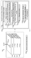
- Functional facility 1000 may have one or more floors, e.g., a first floor 1100, a second floor 1200, a third floor 1300 and a fourth floor 1400.
- System 2000 may herein also be referred to as “monitoring system” or “facility monitoring system”.
- Functional facility monitoring system 2000 may monitor facility usage based on detection and monitoring of the location of one or more computerized mobile client devices 2200 (e.g., first, second and third client devices 2200A-2200C ) located on a first facility floor 1100.
- the one or more client devices 2200 may be associated with one or more respective users (not shown).
- the one or more client devices 2200 may be considered to be comprised in monitoring system 2000.
- Monitoring system 2000 may include one or more external detectors 2400 (e.g., detectors 2400A-2400H ).
- the term "external detector”, as used herein, may refer to any device, apparatus and/or system that is external to computerized client device 2200. Monitoring system 2000 may in some embodiments further include a usage monitoring server 2500.
- the term "external detector” as used herein may refer to a sensor that is external to a client device.
- Some of detectors 2400 may, for example, be comprised in or embodied by LAN connection and/or wireless access points. An access point may, for example, be operative to establish Macro-, Femto- or Pico-cells of wireless communication.
- Parameters of functional facility 1000 may be mapped with reference to a local Cartesian coordinate system (LCS), schematically illustrated in FIGs. 1 and 2 by arrows X(LCS), Y(LCS) and Z(LCS) to obtain map information.
- Initial geographic facility information may be updated periodically or non-periodically (e.g., pseudo-randomly) and/or responsive to an input received by facility monitoring engine 2100 which is indicative of a change in a geographic parameter relating to functional facility 1000.
- Non-limiting examples of geographic facility information may refer to and/or comprise floor level information (e.g., derived from a digital terrain map or DTM associated with the local coordination system; location of walls, windows, doors, stairs, escalators, elevators; parking area including; e.g., indication of the number of free parking lots and, optionally, of their location; the location of toilets, bathrooms and/or of business areas; the name of the companies occupying the business areas and/or the type of service and/or products offered in the business areas; the location of living areas, public and private spaces, maintenance areas and/or restricted areas; the location of emergency equipment, emergency exits; and/or the like.
- floor level information e.g., derived from a digital terrain map or DTM associated with the local coordination system; location of walls, windows, doors, stairs, escalators, elevators; parking area including; e.g., indication of the number of free parking lots and, optionally, of their location; the location of toilets, bathrooms and/or of business areas; the name
- Non limiting examples of geographic facility information may further refer to and/or comprise information about the location of product items in a retail store as well as pricing, product number and/or other information about the items.
- product items may, for example, include apparel, food products, stationary products and/or toys.
- information about the location of point of sales (POS) of product items according to product categories may be mapped in functional facility 1000.
- POS point of sales
- the areas where sportswear and vegetables are offered for sale may be mapped in functional facility 1000.
- the location of each particular product item may be mapped in functional facility 1000.
- the location of a particular brand of sport shoe and of a species of apples, optionally along with associated product pricing may be mapped in functional facility 1000 by the local coordinate system.
- geographic facility information may comprise and/or refer to, for example, location information descriptive of detectors 2400 and associated operating parameters including, for instance, a detector identifier, detector type, boundaries of "dead zones", which are not covered by detectors 2400, permanently or intermittently; operating range (e.g., wireless coverage area); detector location relative to the local coordinate system; sensitivity; range; precision; resolution; accuracy; linearity; response time; and/or the like.
- location information descriptive of detectors 2400 and associated operating parameters including, for instance, a detector identifier, detector type, boundaries of "dead zones", which are not covered by detectors 2400, permanently or intermittently; operating range (e.g., wireless coverage area); detector location relative to the local coordinate system; sensitivity; range; precision; resolution; accuracy; linearity; response time; and/or the like.
- client devices 2200, external detectors 2400 and/or servers 2500 shown in the accompanying figures should by no means to be construed as limiting and is for illustrative purposes only.
- the number of communication links as illustrated herein should by no means be construed as limiting and is for illustrative purposes only.
- the arrows indicating a direction of flow of information over these links should not be construed as limiting.
- Client device 2200, external detectors 2400 and usage monitoring server 2500 may communicate with each other over a communication network 2900.
- Communication network 2900 may be comprised in or added to a facility communication network that interconnects communication components serving facility 1000 and its users.
- monitoring system 2000 may be operative to enable the implementation of methods, processes and/or operations for mapping the location of detectors 2400 in facility 1000 to obtain detector location information, which is respectively associated with detectors 2400.
- mapping of detectors 2400 may be performed on a floor-by-a floor basis.
- mapping and “geographically associating” may herein be used interchangeably.
- monitoring system 2000 may be operative to enable the implementation of methods, processes and/or operations for detecting and tracking client devices 2200 that are located in facility 1000 using detectors 2400. For instance, responsive to detecting the presence of client device 2200A in facility 1000 by the one or more detectors 2400, monitoring system 2000 may be operative to detect, track client device 2200A, based on detector location information which is associated with the detector that detected the presence of client device 2200A.
- facility monitoring engine 2100 may output a heat map which is indicative of the usage of areas in a functional facility during a time interval.
- facility monitoring engine 2100 may also relate to and/or include a module and/or a computerized application.
- Facility monitoring engine 2100 may be realized by one or more hardware, software and/or hybrid hardware/software modules, e.g., as outlined herein.
- the configuration of facility monitoring engine 2100 as outlined herein should by no means be construed as limiting and is therefore for illustrative purposes only.
- facility monitoring engine 2100 may, for example, comprise a detector mapping module 2110 and a mapping module 2120.
- detector mapping module 2110 may store geographic location information of detectors 2400 along with an identifier of the detector(s) 2400.
- mapping module 2120 may register the detection of a client device 2200 along with geographic facility information which is related to the geographic information that is associated with the detector(s) 2400 that detected the presence of the client device.
- Detector mapping module 2110 may, for example, include a wire-based detector mapping module 2112 and a wireless-based detector mapping module 2114 for the geographic mapping of detectors 2400 with respect to their location in functional facility 1000.
- the data descriptive of the geographic mapping of detectors 2400 is stored in monitoring system 2000 as detector location information.
- Wire-based detector mapping module 2112 may, for example, allow the mapping of client devices 2200 located in functional facility 1000.
- wireless-based detector mapping module 2114 may, for example, allow the mapping of wireless access points and/or of client devices 2200 in functional facility 1000.
- mapping module 2120 may provide device location information, responsive to detecting the presence of a client device 2200 by detectors 2400.
- Mapping module 2120 may, for example, comprise a wire-based client device mapping module 2122 and/or a wireless-based client device mapping module 2124.
- facility monitoring engine 2100 may include a registration module 2130.
- Registration module 2130 may, for example, register (e.g., based on an identifier received from a client device 2200 at one or more detectors 2400 ) ingress and egress of client device 2200 into/from functional facility 1000.
- registration module 2130 may store data descriptive of identifiers of client devices 2200 that are approved for use in conjunction with facility monitoring system 2000, e.g., by a system administrator.
- a network authentication module 2700 may be employed which is operative to authenticate client devices that attempt to communicably connect with system components of communication network 2900.
- Network authentication module 2700 may for example comprise an identity service engine (ISE) for verifying eligibility of users to access network 2900.
- ISE identity service engine
- a network authorization phase may be invoked by network authentication module 2700 defining what network resources the authorized user can access.
- facility monitoring engine 2100 may include an operator authentication module 2144 for verifying operator eligibility to use monitoring engine 2100. After authentication, an operator authorization phase may be invoked by operator authentication module 2144 defining what facility monitoring engine resources the authorized operator can access
- facility monitoring engine 2100 may include an anonymization module 2150 for protecting the privacy of the users that are associated with the client devices 2200.
- Detecting operable engagement may, for example, comprise detecting a communication connection made between the client device with a wired and/or wireless local area network (LAN) that is geographically associated with functional facility 1000; detecting the connection of a client device 2200 with a LAN switch located in the functional facility; the connection of a client device 2200 with another client device that is operable engaged with a detector 2400 of functional facility 1000 (e.g., a client device which is connected to a desktop computer via a USB cable); detecting a client device 2200 connecting with the facility's electrical hook-up (not shown), and/or the like.
- LAN local area network
- detectors 2400 are deployed throughout functional facility 1000.
- each personal desk (not shown) and each meeting room desk (not shown) may be equipped with a LAN connection 2920, which may act as (or comprised in) detectors 2400.
- a plurality of access points may be deployed in functional facility 1000 such to ensure a certain minimal signal reception at least in those areas of the facility, which are expected to be regularly frequented by users.
- jamming devices may be deployed in functional facility 1000 in areas where cellular communication would be considered disruptive (e.g., in sanitary areas). In some embodiments, such jamming devices may also act as client device detectors 2400.
- first facility floor 1100 may accommodate offices which may be divided by walls 1102, e.g., creating various distinct floor areas 1105A-1105D, schematically indicated by broken lines.
- Areas 1105A and 1105B may, for example, serve as workspaces (e.g., comprising personal workspaces or meeting rooms),
- area 1105C may, for example, comprise sanitary rooms, and
- area 1105D may comprise kitchen and dining room facilities.
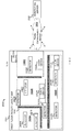
- a computerized client device 2200 may in some embodiments include one or more inertial sensors 2210i and non-inertial sensors 2210ii, a client device processor 2220, a client device memory 2230, a client device navigation engine or positioning module 2250, a client device communication module 2260, a client device user interface 2270, and a client device power module 2280 for powering the various components and/or application engines and/or modules of computerized client device 2200.
- client device processor 2220A, client device processor 2220B and client device processor 2220C indicate that these components are included in client devices 2200A, 2200B and 2200C, respectively.
- a detector 2400 may in some embodiments include a detector processor 2420, a detector memory 2430, a detector monitoring engine 2440, a detector communication module 2460, a detector user interface 2470 and a detector power module 2480 for powering the various components of detector 2400.
- Facility usage monitoring server 2500 may in some embodiments include a server database 2510, a server processor 2520, a server memory 2530, a server monitoring engine 2540, server communication module 2560, a server user interface 2570, and a server power module 2580 for powering the various components and/or application engines or modules of navigation server 2500.
- the various components of the one or more client devices 2200, detectors 2400 and/or monitoring server 2500 may communicate with each other over one or more communication buses (not shown) and/or signal lines (not shown).
- Inertial sensor 2210i may include, for example, one or more accelerometers and/or gyroscopes.
- Non-inertial sensors 2210ii may include, for example, one or more barometers, proximity sensors, altimeters, magnetometers, light sensors, touch screen sensors, receivers of a Global Positioning System, and/or a front and/or back camera.
- Client device memory 2230, detector memory 2430 and/or server memory 2530 may include one or more types of computer-readable storage media.
- client device memory 2230, detector memory 2430 and/or server memory 2530 may include transactional memory and/or long-term storage memory facilities and may function as file storage, document storage, program storage, and/or as a working memory.
- the latter may, for example, be in the form of a static random access memory (SRAM), dynamic random access memory (DRAM), read-only memory (ROM), cache or flash memory.
- client device memory 2230, detector memory (not shown) and/or server memory 2530 may, for example, include a volatile or non-volatile computer storage medium, a hard disk drive, a solid state drive, a magnetic storage medium, a flash memory and/or other storage facility.
- a hardware memory facility may, for example, store a fixed information set (e.g., software code) including, but not limited to, a file, program, application, source code, object code, and the like.
- client device memory 2230 and/or server memory 2530 may, for example, process temporally-based instructions.
- Client device communication module 2260, detector communication module 2460 and server communication module 2560 may, for example, include I/O device drivers (not shown) and network interface drivers (not shown) for enabling the transmission and/or reception of data over network 2900.
- a device driver may, for example, interface with a keypad or a USB port.
- a network interface driver may, for example, execute protocols for the Internet, or an Intranet, Wide Area Network (WAN), Local Area Network (LAN) employing, e.g., Wireless Local Area Network (WLAN)), Metropolitan Area Network (MAN), Personal Area Network (PAN), extranet, 2G, 3G, 3.5G, 4G including for example Mobile WIMAX or Long Term Evolution (LTE) advanced, Bluetooth ® , ZigBeeTM, near-field communication (NFC) and/or any other current or future communication network, standard, and/or system.
- WAN Wide Area Network
- LAN Local Area Network
- WLAN Wireless Local Area Network
- MAN Metropolitan Area Network
- PAN Personal Area Network
- extranet 2G, 3G, 3.5G, 4G including for example Mobile WIMAX or Long Term Evolution (LTE) advanced, Bluetooth ® , ZigBeeTM, near-field communication (NFC) and/or any other current or future communication network, standard, and/or system.
- Server 2500 may refer, for example, to one or more servers or storage systems and/or services associated with a business or corporate entity, including for example, a file hosting service, cloud storage service, online file storage provider, peer-to-peer file storage or hosting service and/or a cyberlocker.
- processor may additionally or alternatively refer to a controller.
- a processor such as for example client device processor 2220 and/or server processor 2520 may be implemented by various types of processor devices and/or processor architectures including, for example, embedded processors, communication processors, graphics processing unit (GPU)-accelerated computing, soft-core processors and/or embedded processors.
- GPU graphics processing unit
- Facility monitoring engine 2100 may be implemented by any suitable device, fully or partially.
- implementations and/or processes and/or elements and/or functions of facility monitoring engine 2100 may be implemented by client device(s) 2200, detector(s) 2400 and/or by monitoring server 2500.
- Respective implementations and/or processes and/or elements and/or functions of facility monitoring engine 2100 are herein referenced by labels 2240, 2440 and 2540, denoting "client device monitoring engine”, “detector monitoring engine” and “server monitoring engine”, respectively, causing facility monitoring system 2000 to operate as disclosed herein.
- client device memory 2230, detector memory 2430 and/or server memory 2530 may include instructions which, when executed e.g.
- client device processor 2220 processor (not shown) of detector 2400, and/or server processor 2520, may cause the execution of a monitoring method, process and/or operation.
- processor 2220 processor (not shown) of detector 2400, and/or server processor 2520, may cause the execution of a monitoring method, process and/or operation.
- client device processor 2220 processor (not shown) of detector 2400, and/or server processor 2520, may cause the execution of a monitoring method, process and/or operation.
- server processor 2520 may cause the execution of a monitoring method, process and/or operation.
- methods and processes disclosed herein may herein be discussed in conjunction with facility monitoring engine 2100.
- One or more hardware, software, and/or hybrid hardware/software modules may realize monitoring engine 2100.
- a method for geographically mapping a detector in a functional facility may include, as indicated by step 4100, receiving detector parameter data from one or more detectors that are located in the functional facility. The method may further include, as indicated by step 4200, geographically associating the received detector parameter data with a geographical location of the functional facility.
- Example procedures of geographically mapping a detector are outlined herein below in more detail.
- a method for geographically mapping a client device may include, as indicated by step 5100, detecting by a detector located and geographically mapped with respect to the functional facility, an operable engagement that is made between a detector and a computerized client device.
- the method may include, as indicated by step 5200, determining a location of the computerized client device.
- the method may include, as indicated by step 5300, providing an output descriptive of the detected operable engagement along with information relating to the determined location point.
- the location point of the client device is determined based on location information of the detector. Example procedures of geographically mapping a client device are outlined herein below in more detail.
- a communication network 2900 may in some embodiments comprise one or more network switches 2910, e.g. for communicably associating detectors 2400 (e.g. LAN connections 2920 ) with monitoring engine 2100 via communication links 2930 and respective ports 2911.
- detectors 2400 e.g. LAN connections 2920
- monitoring engine 2100 via communication links 2930 and respective ports 2911.
- LAN connections 2920 may, for example, comprise or embody some of detectors 2400. It is noted that some parts of communication links 2930 and/or 2940 may be implemented wirelessly.
- a first network switch 2910(I) may, for example, be communicably coupled with a first set of LAN interfaces 2920(I)(A)- 2920(I)(C) and a second network switch 2910(II) may be communicably coupled with a second set of LAN interfaces 2920(II)(A)- 2920(II)(B).
- the respective operative association or coupling between a network switch and a set of LAN interfaces is herein indicated by reference numerals within round brackets.
- the LAN interfaces of a given set i.e. of docking stations which are communicably coupled with the same network switch, may be deployed on the same floor.
- docking stations 2920(I)(A) - 2920(I)(C) of first network switch 2910(I) may be located on first facility floor 1100
- docking stations 2920(II)(A)- 2920(II)(B) may be deployed on second facility floor 1200.
- two or more network switches may be communicably coupled with sets of LAN connections that are located on the same floor.
- docking stations 2920(I)(A) to 2920(I)(B) of first network switch 2910(I) and docking stations 2920(II)(A) - 2920(II)(B) of second network switch 2920(II) may be located on the same facility floor 1300.
- LAN connections which are coupled with the same network switch may be located on different facility floors.
- docking station 2920(II)(A) may be located on first facility floor 1100
- docking station 2920(II)B may be located on fourth facility floor 1400.
- the location mapping of detectors 2400 comprised in or embodied by client LAN interfaces or docking stations 2920, may be performed by wire-based detector mapping module 2112, e.g. as outlined herein.
- the mapping of a LAN connection 2920 with a port of a network switch may include in some embodiments, as indicated by step 7100, communicably coupling, at a first geographic location, a client device to a LAN connection that is communicably coupled with a network switch via a port.
- the port may be associated with one of a plurality of VLANs which are associated with the given network switch.
- the client device may have an authorized and, optionally known, device identifier.
- client device 2200A may be communicably coupled with a first port 2911(I)(A) of first network switch 2910(I).
- Client device 2200A may, for example, be communicably coupled with first network switch 2910(I) by docking client device 2200A onto a docking station that comprises a LAN connection.
- a client device identifier may be, for example, the Media Access Control (MAC) Address of the device.
- Further data that may be received from a client device may be descriptive of the client device certificate name, username, organizational unit affiliation, team affiliation and/or the like.
- Username, organizational unit affiliation, team affiliation and MAC address may be used for inventory purposes, for example, to identify the users.
- the mapping method may, in an embodiment, further include receiving an identifier of the client device (e.g. "0xAA").
- a client device identifier may be received by monitoring system 2000 (e.g. by wire-based detector mapping module 2112 ) .
- the client device identifier may be fetched or provided.
- information descriptive of the first geographic information may be received by system 2000 (e.g. by wire-based detector mapping module 2112 ) .
- the first geographic location information may be provided by an administrator of monitoring system 2000.
- the mapping method may include, querying all network switches and, if applicable, the VLANs associated with the network switches, to determine which port of the network switches is currently communicably coupled with the client device (e.g., device 2200A ) employed for conducting the mapping procedure. If for example a match is found between the ID of device 2200A and a port, the port is mapped with the geographic location of the LAN connection 2920 (or the corresponding desk) to which device 2200A is connected. The same procedure may then be repeated for the next LAN connection 2920.
- the client device e.g., device 2200A
- caching or a caching procedure may be employed for mapping ports of network switches with LAN connections 2920, as exemplified herein below in more detail.
- the mapping method which employs caching may include, in an embodiment, determining if the client device with known and authorized identifier information is identified as having previously been connected to a LAN network entity (which comprises the port) or not.
- a LAN network entity which comprises the port
- Such LAN network entity may comprise a given network switch and, optionally, a given VLAN of a plurality of VLANs that are associated with the given network switch.
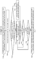
- wire-based detector mapping module 2112 may first determine if client device 2200A had already once been connected before with the given network switch and the given VLAN in a preceding mapping procedure, or not. If the result of the latter procedure is that client device 2200A was once connected with the given network switch and the given VLAN thereof in a preceding mapping procedure, then only the ports of same given VLAN may be queried (step 7305 ) . If, responsive to the querying, the ID of client device 2200A is found to be associated with one of the ports of the given VLAN, the said port is mapped with the LAN connection 2920 to which client device 2200A is currently connected to.
- step 7400 & 7500 the ID of client device 2200A is not found to be associated with one of the ports of the given VLAN. If, responsive to said querying, the ID of client device 2200A is found to be associated with one of the ports of any of the VLANs of the given network switch, then said port is mapped with the respective LAN connection 2920 ( steps 7600 & 7800 ) . Step 7800 is outlined in more detail further below. If no match is found between a port and the ID of client device 2200A, then all VLANs of all switches may be queried until such match is found (steps 7400 & 7500 ) .
- VLAN identifiers may be blacklisted (not read) and some whitelisted.
- Whitelisted VLAN identifiers (or simply VLANs) may be queried in the LAN connection mapping procedure, whereas blacklisted VLANs may not be queried.
- a step of authenticating a client device may be performed by network authentication module 2700 which is operative to authenticate client devices that attempt to communicably connect with system components of communication network 2900.
- network authentication module 2700 which is operative to authenticate client devices that attempt to communicably connect with system components of communication network 2900.
- different levels of authorization may be associated with different client devices 2200. Additional or alternative measures may be employed to prevent unauthorized access of client devices to communication network 2900.
- Network authentication module 2700 may, for example, employ wireless protocol IEEE 802.1X on network 2900, e.g., by Cisco ® Identity Service Engine (ISE) and/or any known or future communication protocol.
- client device identifiers may be readout by employing an application programming interface (API).
- APIs include representational state transfer (REST), and simple network management protocol (SNMP).
- the method may further include, as indicated by step 7700, determining if the port of the network switch to which the client device is connected, is "blacklisted".
- a port may be considered “blacklisted” if it is already employed or reserved for connecting a component to the network switch and, therefore, is not available for connection with a client device.
- port # n of first network switch 2910(I) and port #1 of second network switch 2910(II) may be blacklisted as they are in use for communicably coupling first network switch 2910(I) with second network switch 2910(II), e.g. via communication link 2931.
- the method may, in an embodiment, include, as indicated by step 7800, storing in system 2000 information which is descriptive of the first geographic information in association with data descriptive of the port.
- the geographic information may be the location of a desk or room, which is geographically mapped in system 2000, and the corresponding LAN connection.
- a LAN connection identifier may be stored in association with the first geographic location information.
- the VLAN which is associated with the port of the network switch is stored in association with the geographic location information.
- a time stamp may be stored in association with the first geographic information which is stored in association with the identifiers of the network switch and port.
- the time stamp indicates a time of recordation of the geographic association of the port(s) or detector(s).
- another time stamp of recordation may be associated with the ports prior to such network reconfiguration.
- geographic location information of a detector may be attributed with a start and an end time defining the time period during which the detector's geographic mapping was valid.
- the method may include repeating steps 7100-7800 at the next geographic location which features an arrangement for communicably coupling a client device to a network switch of functional facility 1000.
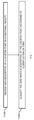
- FIG. 8 illustrates a flow chart of a method for geographically mapping client devices using wire-based LAN connections.
- Such method may include, as indicated by step 8100, detecting by detectors located and geographically mapped with respect to the functional facility, an operable engagement that is made between the plurality of detectors and computerized client devices.
- the step of detecting such operable engagement may comprise or may be followed by reading an identifier respective of the plurality of detected client devices and of the corresponding network switch (and optionally, of corresponding VLAN lists) along with the respective port identifier. For instance, referring to FIG.
- wire-based client device mapping module 2122 may receive (e.g. through readout or fetching) identifiers of client device 2200E, LAN interface 2920(I)(B), of first network switch 2911(I) and of port #46.
- wire-based client device mapping module 2122 may receive (e.g. read) VLAN lists.
- a client device identifier may be, for example, the Media Access Control (MAC) Address of the device.
- the client device identifier may be descriptive of the client device certificate name, username, organizational unit affiliation, team affiliation and/or the like.
- Username, organizational unit affiliation, team affiliation and MAC address may be used for inventory purposes, for example, to identify the users.
- Identifiers which are received in a present readout procedure of step 8100 may herein be referred to as "current identifiers".
- the method may include, as indicated by step 8200, storing the received identifiers as current identifiers in a database 2160.
- Database 2160 may, for example, be embodied (e.g. fully or partially) by server database 2510 of monitoring server 2500.
- the method may include, as indicated by box 8300, determining if there is a discrepancy between the current identifiers and identifiers (herein: "reference identifiers") which were received in a preceding readout cycle, by comparing the current identifiers against the reference identifiers.
- the method may further include, as indicated by box 8400, updating the list of reference identifiers to obtain an updated list of reference identifiers, in case of a discrepancy.
- Comparing the current identifiers against reference identifiers and updating the list of reference identifiers may, for example, be accomplished as follows.
- Each reference identifier may, for example, be tagged as «New», «Last Seen» and with time stamps named «Start Time», or «End Time» which indicate times of recordation of wireless and/or wire connection start and end times.
- a current client identifier that is not yet listed in the list of reference identifiers may be added to the said reference identifier list and tagged as «New».
- the identifier of client device 2200C may be listed as «New» if its identifier was not recorded in any of the previous cycles.
- the said reference identifier may be tagged as «Last Seen» in the list.
- a reference identifier may be tagged as «Last Seen» if the reference identifier was recorded in the previous readout cycle and a matching current identifier was found in the current readout cycle.
- the identifier of client device 2200A may be tagged as «Last Seen» if it was already identified as registered (listed) in the readout cycle which precedes the current readout cycle.
- the said reference identifier may be associated with an «End Time».
- the identifier of client device 2200C may be associated with a corresponding «End Time» if the identifier was registered in the preceding readout cycle, yet no matching identifier was found therefor in the current readout cycle.
- an «End Time» may be associated with an identifier is which is the time of recordation of the current readout at which, the client "disappeared”.
- readout for checking occupancy may be triggered periodically, e.g., every 5 minutes, 6 minutes or10 minutes.
- readout for checking occupancy may be triggered responsive to a notification received from a component of system 2000, e.g., responsive to an input received from a network switch. According to some embodiments, such trigger may override a periodic readout cycle.
- Each addition and/or change of recordation in an entry of the list of identifiers entry may be associated with a time stamp.
- FIG. 9 schematically illustrates a block diagram illustration of a wireless communication system deployed in a functional facility.
- detectors may be embodied or comprised in wireless access points.
- Wireless access points may be employed in wireless-based client device mapping in a functional facility.
- a detector having wireless communication capabilities may herein be referred to as "wireless access point”.
- detectors 2400E-2400H may herein also be referred to as wireless access points 2400E-2400H.
- a client device may communicate with access points over wireless communication links 2950, schematically illustrated herein by broken lines.
- Access points may communicate with facility monitoring engine 2100 over communication links 2960, which may be implemented by wire and/or wireless communication.
- Wireless access points 2400 may each comprise one or more antennas 2462 allowing wireless communication with client devices 2200 via antennas 2262, which may be part of the client device communication module 2260.
- antenna may include any suitable configuration, arrangement and/or configuration of one or more antenna elements, components, units, assemblies and/or arrays.
- wireless access points 2400E-2400H may be geographically mapped with respect to functional facility 1000 and stored as location information in system 2000.
- wireless-based client device mapping module 2124 may employ various techniques for estimating a location of one or more client devices, based on various measured values of electromagnetic (EM) radiation parameters received at the access points from the client devices. These location estimation techniques may, for example, be employed periodically or in a non-periodic manner (e.g. pseudo-randomly) by monitoring engine 2100.
- EM electromagnetic
- Such EM radiation parameters may, for example, include received signal strength (RSS), signal time-of-flight, phase difference, and/or the like. Measured values of parameters may be employed in trilateration and/or triangulation techniques for estimating the location of a client device. Location estimation may be performed by employing optimization techniques such as, for example, a Non Linear Model Fit.
- RSS received signal strength
- signal time-of-flight phase difference
- phase difference phase difference
- Measured values of parameters may be employed in trilateration and/or triangulation techniques for estimating the location of a client device. Location estimation may be performed by employing optimization techniques such as, for example, a Non Linear Model Fit.
- a location of client device 2200C may, for example, be estimated based on the RSS values measured at two or more access points 2400E-2400H and which are provided or reported as received signal strength indications (RSSI) to facility monitoring engine 2100.
- Wireless-based client device 2124 ( FIG. 1 ) may, for example, estimate the location of client device 2200C based on parameter values of the EM radiation that is emitted by client device 2200C and based on parameter values of the EM radiation received by the one or more access points 2400E-2400H and which originated from the same client device 2200C.
- EM parameter values may be provided to monitoring engine 2100 in association with respective client device and access point identifiers.
- wireless-based client device mapping module 2124 may receive values (e.g., RSSI values) related to one or more parameters of EM radiation emitted by client device 2200G and which are received by one or more access points 2400E-2400H in respective association with an identifier of client device 2200G and the one or more access points 2400E-2400H.
- Estimated client device location points may be stored in system 2000 (e.g., in database 2160 ) as client device location information.
- time stamps e.g., T1 (client device 2200D ), T2 (client device 2200D),..., Tn (client device 2200D )
- T1 client device 2200D
- T2 client device 2200D
- Tn client device 2200D
- EM radiation may be received at access points (e.g., 2400E-2400H ) passively. More specifically, some access points, while not participating in establishing and maintaining a communication link, may receive signals related to such link.
- access points e.g., 2400E-2400H
- access points may be operably associated (e.g., communicably coupled) with one or more Wireless Management Systems 2600.
- Wireless Management Systems include Cisco ® Wireless LAN Controller, Cisco ® Prime Infrastructure, and Cisco ® Mobility Services Engine (not shown).
- monitoring engine 2100 may receive (e.g., read) processed EM radiation parameter values which are related to EM radiation emitted by client device 2200, from such Wireless Management System(s) (not shown).
- monitoring engine 2100 may apply a wireless client device filter logic on information that is wirelessly received at access points from a plurality of client devices.
- the wireless client device filter logic may be employed for determining for which of the plurality client devices a location shall be estimated by facility monitoring engine 2100 based on values related to EM radiation received at the access points from the corresponding device. Accordingly, by applying the client device filter logic, a selection of client devices is made from the plurality of client devices. Applying the wireless client device filter logic may for example return no client devices or one or more of the plurality of client devices. In other words, the wireless client device filter logic employed by monitoring engine 2100 may determine whether the received information respective of the wireless client devices meets a "location estimation criterion" or not.
- the location estimation criterion may, for example, relate to one or more of the following parameters: service set identifier (SSID); building location (e.g., in cases where the same SSID is associated with office buildings of a given company and which are located at different locations); minimum time period at which EM radiation is received; and/or authentication information received at the access points from the client devices.
- SSID service set identifier
- building location e.g., in cases where the same SSID is associated with office buildings of a given company and which are located at different locations
- minimum time period at which EM radiation is received e.g., EM radiation carrying information emitted by client device 2200C
- EM radiation carrying information emitted by client device 2200C may be received at access points 2400E, 2400F, 2400G and 2400H
- EM radiation carrying information emitted by client device 2200D may be received at wireless access points 2400F and 2400H.
- the information emitted via EM radiation from client device 2200C may comprise authentication information which matches a location estimation criterion employed by the wireless client device filter logic.
- the information emitted via EM radiation by client device 2200D may not meet a location estimation criterion. Accordingly, monitoring engine 2100 may estimate the location for client device 2200C but not for client device 2200D.
- wireless-based client device mapping module 2124 may comprise a client device location module that is provided by a vendor of wireless networking equipment and which estimates the location of a client device in functional facility 1000.
- wireless-based client device mapping module may comprise a Cisco ® services mobility service module providing facility monitoring system 2000 with data descriptive of the location of a client device, e.g., based on RSSI.
- the location of a client device does not necessarily have to be estimated by such a vendor-provided device location module.
- the wireless client device filter logic may not be applied in configuration of systems 2000 where a client device location module is provided by a vendor of wireless networking equipment.
- data descriptive of a client device location may be fused by monitoring engine 2100 with data descriptive of values provided by inertial sensors 2210i and/or non-inertial sensors 2210ii ( Fig. 3 ).
- FIG. 10A schematically illustrates a flow chart of a method for geographically mapping client devices based on wireless signals, according to some embodiments.
- the method may include, as indicated by step 10100, receiving data descriptive of values of parameters that are related to EM radiation emitted by a client device.
- the method may in some embodiments optionally include employing a vendor-independent position estimation method to obtain, based on the received data, location information for the client device.
- the method may further include, as indicated by box 10200, receiving the location information of the client device based on the received data.
- location information of a client device may be obtained from a wireless management module and/or by employing a vendor-independent position estimation method.
- monitoring engine 2100 may apply location filter logic on the estimated client device location information of a plurality of client devices to obtain location information for a selection of respective client devices.
- Such filter logic may, for example, be aimed at "smoothing" out data points that are descriptive of time vs location, e.g. to remove outliers.
- filtering may be employed with respect to comparably short time periods or dwell times of client devices at estimated location points. By smoothing such data points, comparably short periods of dwell time of a client device at an estimated location may be disregarded in a facility usage analysis. Accordingly, the location points at which client devices are estimated to be located for a comparably short dwell time period are disregarded.
- the location filter logic may, for example, comprise a sliding moving average or a sliding moving median, a low-pass filter technique or the like.
- values of measured parameters of time and location are scaled.
- scaling as used herein, as well as grammatical variations thereof, may also encompass “normalizing”.
- values of x/y coordinates may be scaled to range from 0 to 1 (or 0-100%) of a floor's dimension, i.e. [0,1] .
- time measurements may for example be scaled to a scale ranging from 0 to 1, i.e. [0,1], and expressed in units of milliseconds.
- cluster analysis may be performed on data which is descriptive of estimated location points of wirelessly communicating client devices and associated time stamps of recordation of the estimated location points.
- the cluster analysis may be performed by monitoring engine 2100, e.g. by wireless-based client device mapping module 2124 of mapping module 2120 .
- Each one of a plurality of wireless client devices may be grouped by clustering to obtain data clusters.
- location points and time stamps respective of each one of a plurality of wireless client devices 2200 may be grouped according to the geographic distribution of the location points as a function of time. For example, for a given time stamp, a group of location points may be associated with a cluster if they are distributed in a certain geographic area within a relatively higher density than other location points.
- Cluster analysis techniques that may be employed may include, for example, Density-based Spatial Clustering of Applications with Noise (DBSCAN), K-Means, or the like.
- monitoring engine 2100 may in some embodiments determine a center point for each cluster. Further, with respect to each location point in a cluster which is associated with a given client device, a time stamp ( «start time») is recorded at which the appearance of location point is registered. If applicable, for each client device a time stamp ( «end time») is recorded at which the disappearance of the time stamp is registered by monitoring engine 2100, subsequent to recordation of the time stamp of appearance ( «Start time») of the same client device. In addition, for each estimated location point which is associated with the same client device in a cluster, a distance may be determined between the client device and the cluster's centerpoint.
- the location point may remain a member of the cluster or be removed from the cluster, e.g., by associating the location point to another cluster.
- the number of location points in a cluster may thus be updated dynamically by monitoring engine 2100.
- the cluster analysis may be repeated at (e.g. regular) intervals.
- the usage of functional facility 1000 may thus be facilitated by monitoring engine 2100 which is operative to dynamically determine clusters of estimated location points of wireless client devices (e.g. client devices 2200A-2200C ) .
- Estimated location points of client devices 2200 may be associated with floor numbers. Accordingly, cluster analysis may, in some embodiments, be performed on a floor-by-floor basis.
- a method for filtering and clustering of data descriptive of geographically mapped client devices may include, in some embodiments, as indicated in step 10300, smoothing data with respect to dwell times of client devices at location points.
- the method may in some embodiments further include, as indicated by step 10400, scaling data which is descriptive of estimated location points of client devices to obtained scaled data.
- the method may further include, as indicated by step 10500, performing cluster analysis, e.g. according to the geographic distribution of the location points as a function of time on the scaled data, to obtain clusters of estimated location points. Based on the data clusters, usage of a functional facility may be determined or monitored.
- cluster analysis e.g. according to the geographic distribution of the location points as a function of time on the scaled data
- location point information of a functional facility may be classified according to a dwell time criterion into a selected one of two or more location classifications of, e.g. "free", "occupied” and optionally “warm”, according to one or more classification criteria by a classifier engine (not shown) employed by monitoring engine 2100.
- classification criteria may relate to thresholds of vacant time periods, dwell time periods of a client device at a location point, and the identifier of the client device, as outlined herein below in greater detail.
- a location point may be classified as "occupied” if a client device is associated with network 2900 during a predetermined time period at the location point. Further, a location point may be classified as “free” if no client device is associated with network 2900 at that location. Finally, a location point may be classified as "warm” if a client device leaves a location point and the same client device returns to the previous location point within a certain time interval and no other client device connected to the said location point during this time interval.
- time interval and “time period” may be used interchangeably.
- a location point may be classified as “free” at time period(s) during which the location point is neither classified as “warm” or “occupied” by client devices, provided that such time period exceeds a first vacant time period threshold. In some embodiments, a location point may remain classified as “free” when the said time period exceeds the first vacant time period threshold and any dwell time which is measured from the time stamp at which the device is not registered with the location does not exceed a first dwell time period threshold.
- a location point may be classified as "occupied" at time period(s) during which the location point was continuously occupied by one or more client devices, provided that such time period exceeds a second dwell time period threshold.
- the above noted first dwell time period is smaller than or can be equal to the second dwell time period threshold.
- the location point may remain classified as "occupied” even if the client device has left and returned to the same location period within a time period which does not exceed a second minimum vacant threshold.
- the first vacant threshold is greater than or equal to the second minimum vacant threshold.
- monitoring engine 2100 may, in some embodiments, only consider or register that a certain location of functional facility 1000 is used by a client device when the location information which is associated with the device meets the corresponding classification (e.g. dwell time) criterion.
- a client device may be considered to "use” a certain location in functional facility 1000, when monitoring engine 2100 determines that the client device continuously occupies or is continuously located at about the same location for a time period which exceeds the second dwell time period threshold.
- the second dwell time period threshold may, for example, be set to 10 minutes, 20 minutes or 30 minutes. In the following two scenarios, a threshold time period with a dwell time of 30 minutes is exemplified.
- client device 2200C which is connected with the same port (e.g. via docking station 2920(II)(1) from 9:00AM to 11:00AM is considered a single use or visit.
- client device 2200C connected with docking station 2920(I)(1) for 30minutes from 9:00AM to 9:30AM (e.g. located on a personal desk) and from 9:30 AM to 10:00AM with docking station 2920(II)(1) (e.g. located in a meeting room) and then again with docking station 2920(I)(1) from 10:00AM to 11:00 AM (located on the same personal desk), is considered or registered as three distinct uses or visit.
- time periods of continuous disconnection may for example be 60 seconds or less, 50 seconds or less, 40 seconds or less, 30 seconds or less, 20 seconds or less, 10 seconds or less, 5 seconds or less, 2 seconds or less, or 1 second or less.
- the time periods that may be disregarded may be defined by a fraction of the second dwell time period threshold such as, for instance, 1/10 or less, 1/15 or less, or 1/20 or less, or 1/50 or less of the second dwell time period threshold.
- a location point may be classified as "warm” if a client device which was registered as occupying a location point leaves or unregisters from the location point; and the time period that has passed since the client device has left the location point does not exceed a time period which is greater than the first vacant time period threshold. In some embodiments, the location point may remain classified as "warm” even if another or the same client device is again registered as being present at the location point for a time period which does not exceed a minimum dwell time period. While the following example scenarios are outlined with respect to client devices 2200B and 2200C, this should by no means construed limiting. Therefore, the described example scenarios are equally applicable to other wireless and non-wireless client devices as well.
- a location point classification method may include in some embodiments, as indicated by step 11100, receiving data which is descriptive of a location point in a functional facility.
- the method may further include, as indicated by step 11200, classifying the data which is descriptive of the location point according to classification criteria, e.g., by a classifier.
- classification criteria may relate to thresholds of vacant time periods, dwell time periods of a client device at a location point, and to the identifier of the client device, as outlined herein below in greater detail.
- only «warm» desks are returned, which may, for example, be achieved by determining the difference between «occupied and warm» - «occupied only».
- anonymizing an identifier may refer to anonymizing one or more identifiers of a client device, of a user, or both.
- data descriptive of identifiers of client devices may be anonymized to yield anonymized data for protecting the privacy of the users that are associated with the client devices which location are tracked by monitoring engine 2100.
- Anonymization may be performed while simultaneously enabling utility of the resulting anonymized data with respect to monitoring of facility usage.
- One or more of a variety of data anonymization techniques may be executed by anonymization module 2150 of monitoring engine 2100 to yield anonymized data.
- An example of an anonymization technique that may be employed includes hash encoding, optionally in combination with a randomly (or pseudo-randomly) generated string, also known as "salt".
- the random string may remain unchanged or constant for a given set of data to be anonymized.
- the random string may change dynamically, e.g., periodically.
- an anonymization technique may include the procedure of receiving data which is descriptive of an anonymization level to be applied by anonymization module 2150.
- the number of anonymization levels that may be applied by anonymization module 2150 may vary for different embodiments and should not be limited to the examples outlined herein.
- the non-anonymization level may allow unlimited tracking of client devices 2200, i.e. no restrictions are imposed as to the privacy of the users of the client devices.
- the mid-anonymization level may provide some privacy protection to the users of client devices 2200.
- the high-anonymization level may provide a higher level of anonymization, i.e. privacy protection, compared to the mid-anonymized level.
- the mid- and high-anonymization may each have two or more anonymization sublevels.
- the plurality of anonymization sublevels may, for example, be defined by respective levels of client device traceability. Accordingly, in some embodiments, the applied anonymization technique may include the procedure of receiving data which is descriptive of a device traceability level which may then applied by anonymization module 2150.
- a first traceability level which may herein also be referred to as "single visit level”
- the identifier(s) of the client device and/or of the user(s) which is associated with the client device's identifier(s) is anonymized.
- anonymization module 2150 may anonymize the corresponding identifier(s).
- time stamps which indicate a time of recordation of a location of a client device may not be truncated, i.e., recorded "as is”.
- a second traceability level for example, which may herein also be referred to as "intra-time level"
- the identifier(s) respective of a client device may be associated with identical anonymizing identifiers during a certain time period. Accordingly, occurrences of detections by the one or more detectors within the time period, of the client device within the time period may be linked. For example, an identifier of client device 2200C that is detected for the first time within a time period by a detector (e.g., detector 2400B ), may be anonymized to yield anonymized data descriptive of an anonymized identifier which is unique to client device 2200C.
- a detector e.g., detector 2400B
- the same anonymized identifier may remain associated with client device 2200C as long as the time period has not passed.
- other anonymized data may be associated with client device 2200C.
- the other anonymized data may remain associated with the same client device as long as the time period has not passed.
- the time periods may alter dynamically. Such time period may, for example, have a duration of 4 hours, 8 hours, 12 hours, 24 hours or 36 hours.
- the time stamp for starting the measurement of such a time period may vary and start, for example, at 0:00AM, 6:00AM, 12:00AM. In this second traceability level, when, for example, the periods are calendrical days, the hours, minutes and seconds of the time stamps are truncated.
- the same anonymized data may remain associated with the respective client device, irrespective of any time period.
- the same anonymization data may remain associated with client device 2200B, once the presence of client device 2200B in functional facility 1000 is detected.
- the time stamp is truncated in its entirety.
- an anonymization technique may include, in some embodiments, as indicated by step 12100, receiving data which is descriptive of an anonymization level to be applied on data which is descriptive of an identifier of a client device.
- the method may further include, as indicated by step 12200, receiving data which is descriptive of a traceability level to be implemented in a client device which is associated with anonymized identifier data.
- FIG. 13 shows an example heat map image which is descriptive of the usage of a floor in a functional facility by client devices over a prolonged time period.
- the heat map refers to the usage during a time period of 72 hours, e.g. from April 1 2015 - April 3 2015.
- FIG. 14 shows an example snapshot image of the floor recorded at a first time of recordation, e.g. at 8:00AM on April 1 2015.
- FIG. 15 shows an example snapshot image of the floor recorded at a second time of recordation, e.g. at 10:30AM on April 1 2015.
- FIG. 16 shows an example snapshot image of the floor recorded at a third time of recordation, e.g. at 1 PM on April 1 2015
- Areas with green coloration indicate that an area is vacant at the time of recordation of the snapshot image. Areas with red coloration indicate that an area is occupied at the time of recordation of the snapshot.
- FIG. 17 schematically illustrates a product of manufacture 17000, according to some embodiments.
- Product 17000 may include a non-transitory tangible machine-readable storage medium 17100 to store logic 17120, which may be used, for example, to perform at least some of the functionality of facility monitoring engine 2100.
- each of the verbs, "comprise” “include” and “have”, and conjugates thereof, are used to indicate that the object or objects of the verb are not necessarily a complete listing of components, elements or parts of the subject or subjects of the verb.
- real-time may also encompass the meaning of the term “substantially in real-time” or “about real-time”.
- the platform and associated receivers may detect communication signals emitted from computerized end-user devices which may, for example, include a multifunction mobile communication device also known as "smartphone", a personal computer, a laptop computer, a tablet computer, a personal digital assistant, a wearable device, a handheld computer, a notebook computer, a vehicular device and/or a stationary device
- a multifunction mobile communication device also known as "smartphone”
- a personal computer a laptop computer, a tablet computer, a personal digital assistant, a wearable device, a handheld computer, a notebook computer, a vehicular device and/or a stationary device
- detection as well as grammatical variations thereof may encompass any processes that enable such “detection”, including sensing and/or monitoring.
- a digital computer system is programmed to perform particular functions pursuant to computer-executable instructions from program software that implements a method disclosed herein, it in effect becomes a special purpose computer particular to an embodiment of the method disclosed herein.
- the techniques necessary to achieve this are well known to those skilled in the art and thus are not further described herein.
- the methods and/or processes disclosed herein may be implemented as a computer program product such as, for example, a computer program tangibly embodied in an information carrier, for example, in a non-transitory computer-readable and/or non-transitory machine-readable storage device and/or in a propagated signal, for execution by or to control the operation of a data processing apparatus including, for example, one or more programmable processors and/or one or more computers.
- non-transitory computer-readable storage device and “non-transitory machine-readable storage device” encompasses distribution media, intermediate storage media, execution memory of a computer, and any other medium or device capable of storing for later reading by a computer program implementing embodiments of a method disclosed herein.
- a computer program product can be deployed to be executed on one computer or on multiple computers at one site or distributed across multiple sites and interconnected by a communication network.
- These computer readable program instructions may be provided to a processor of a general purpose computer, special purpose computer, or other programmable data processing apparatus to produce a machine, such that the instructions, which execute via the processor of the computer or other programmable data processing apparatus, create means for implementing the functions/acts specified in the flowchart and/or block diagram block or blocks.
- These computer readable program instructions may also be stored in a computer readable storage medium that can direct a computer, a programmable data processing apparatus, and/or other devices to function in a particular manner, such that the computer readable storage medium having instructions stored therein comprises an article of manufacture including instructions which implement aspects of the function/act specified in the flowchart and/or block diagram block or blocks.
- the computer readable program instructions may also be loaded onto a computer, other programmable data processing apparatus, or other device to cause a series of operational steps to be performed on the computer, other programmable apparatus or other device to produce a computer implemented process, such that the instructions which execute on the computer, other programmable apparatus, or other device implement the functions/acts specified in the flowchart and/or block diagram block or blocks.
- engine may comprise one or more computer modules, wherein a module may be a self-contained hardware and/or software component that interfaces with a larger system (Alan Freedman, The Computer Glossary 268, (8th ed. 1998)).
- a module may comprise a machine or machines executable instructions.
- a module may be embodied by a circuit or a controller programmed to cause the system to implement the method, process and/or operation as disclosed herein.
- a module may be implemented as a hardware circuit comprising, e.g., custom VLSI circuits or gate arrays, off-the-shelf semiconductors such as logic chips, transistors, or other discrete components.
- a module may also be implemented in programmable hardware devices such as field programmable gate arrays, programmable array logic, programmable logic devices or the like.
- operably coupled may encompass the meanings of the terms “responsively coupled”, “communicably coupled”, and the like.
- Discussions herein utilizing terms such as, for example, “processing”, “computing”, “calculating”, “determining”, “establishing”, “analyzing”, “checking”, “estimating”, “deriving”, or the like, may refer to operation(s) and/or process(es) of a computer, a computing platform, a computing system, or other electronic computing device, that manipulate and/or transform data represented as physical (e.g., electronic) quantities within the computer's registers and/or memories into other data similarly represented as physical quantities within the computer's registers and/or memories or other information storage medium that may store instructions to perform operations and/or processes.
- the term “determining” and “estimating” may also refer to “heuristically determining” and “heuristically estimating”, respectively.
Landscapes
- Business, Economics & Management (AREA)
- Engineering & Computer Science (AREA)
- Human Resources & Organizations (AREA)
- Economics (AREA)
- Strategic Management (AREA)
- Entrepreneurship & Innovation (AREA)
- Physics & Mathematics (AREA)
- General Physics & Mathematics (AREA)
- Theoretical Computer Science (AREA)
- Tourism & Hospitality (AREA)
- Marketing (AREA)
- General Business, Economics & Management (AREA)
- Operations Research (AREA)
- Quality & Reliability (AREA)
- Development Economics (AREA)
- Game Theory and Decision Science (AREA)
- Educational Administration (AREA)
- Computer Networks & Wireless Communication (AREA)
- Signal Processing (AREA)
- Computer Security & Cryptography (AREA)
- Data Mining & Analysis (AREA)
- General Engineering & Computer Science (AREA)
- Health & Medical Sciences (AREA)
- General Health & Medical Sciences (AREA)
- Primary Health Care (AREA)
- Emergency Management (AREA)
- Evolutionary Biology (AREA)
- Computing Systems (AREA)
- Computer Hardware Design (AREA)
- Evolutionary Computation (AREA)
- Computer Vision & Pattern Recognition (AREA)
- Bioinformatics & Computational Biology (AREA)
- Bioinformatics & Cheminformatics (AREA)
- Artificial Intelligence (AREA)
- Life Sciences & Earth Sciences (AREA)
- Probability & Statistics with Applications (AREA)
- Alarm Systems (AREA)
- Telephonic Communication Services (AREA)
- Management, Administration, Business Operations System, And Electronic Commerce (AREA)
Priority Applications (14)
| Application Number | Priority Date | Filing Date | Title |
|---|---|---|---|
| EP16162515.7A EP3226182A1 (fr) | 2016-03-29 | 2016-03-29 | Dispositif, système et procédé de surveillance d'utilisation d'installations fonctionnelles |
| CN202210257255.0A CN114760583A (zh) | 2016-03-29 | 2017-03-28 | 用于监控功能设施的使用的系统和方法 |
| KR1020207014460A KR102406440B1 (ko) | 2016-03-29 | 2017-03-28 | 기능 시설의 사용을 모니터링하기 위한 장치, 시스템 및 방법 |
| KR1020187025440A KR102183382B1 (ko) | 2016-03-29 | 2017-03-28 | 기능 시설의 사용을 모니터링하기 위한 장치, 시스템 및 방법 |
| KR1020207033195A KR102395608B1 (ko) | 2016-03-29 | 2017-03-28 | 기능 시설의 사용을 모니터링하기 위한 장치, 시스템 및 방법 |
| PCT/EP2017/057243 WO2017167709A1 (fr) | 2016-03-29 | 2017-03-28 | Dispositif, système et procédé de surveillance de l'utilisation d'installations fonctionnelles |
| CN201780013008.3A CN108701282B (zh) | 2016-03-29 | 2017-03-28 | 用于监控功能设施的使用的设备、系统和方法 |
| JP2018563943A JP6738443B2 (ja) | 2016-03-29 | 2017-03-28 | 機能施設の使用をモニタリングするための装置、システムおよび方法 |
| US16/088,772 US10600013B2 (en) | 2016-03-29 | 2017-03-28 | Device, system and method for monitoring usage of functional facilities |
| SG11201805528SA SG11201805528SA (en) | 2016-03-29 | 2017-03-28 | Device, system and method for monitoring usage of functional facilities |
| EP17713675.1A EP3437033A1 (fr) | 2016-03-29 | 2017-03-28 | Dispositif, système et procédé de surveillance de l'utilisation d'installations fonctionnelles |
| US16/788,523 US11080634B2 (en) | 2016-03-29 | 2020-02-12 | Device, system and method for monitoring usage of functional facilities |
| JP2020122974A JP7150353B2 (ja) | 2016-03-29 | 2020-07-17 | 機能施設の使用をモニタリングするための装置、システムおよび方法 |
| US17/135,452 US11386372B2 (en) | 2016-03-29 | 2020-12-28 | Device, system and method for monitoring usage of functional facilities |
Applications Claiming Priority (1)
| Application Number | Priority Date | Filing Date | Title |
|---|---|---|---|
| EP16162515.7A EP3226182A1 (fr) | 2016-03-29 | 2016-03-29 | Dispositif, système et procédé de surveillance d'utilisation d'installations fonctionnelles |
Publications (1)
| Publication Number | Publication Date |
|---|---|
| EP3226182A1 true EP3226182A1 (fr) | 2017-10-04 |
Family
ID=55646366
Family Applications (2)
| Application Number | Title | Priority Date | Filing Date |
|---|---|---|---|
| EP16162515.7A Withdrawn EP3226182A1 (fr) | 2016-03-29 | 2016-03-29 | Dispositif, système et procédé de surveillance d'utilisation d'installations fonctionnelles |
| EP17713675.1A Pending EP3437033A1 (fr) | 2016-03-29 | 2017-03-28 | Dispositif, système et procédé de surveillance de l'utilisation d'installations fonctionnelles |
Family Applications After (1)
| Application Number | Title | Priority Date | Filing Date |
|---|---|---|---|
| EP17713675.1A Pending EP3437033A1 (fr) | 2016-03-29 | 2017-03-28 | Dispositif, système et procédé de surveillance de l'utilisation d'installations fonctionnelles |
Country Status (7)
| Country | Link |
|---|---|
| US (3) | US10600013B2 (fr) |
| EP (2) | EP3226182A1 (fr) |
| JP (2) | JP6738443B2 (fr) |
| KR (3) | KR102406440B1 (fr) |
| CN (2) | CN114760583A (fr) |
| SG (1) | SG11201805528SA (fr) |
| WO (1) | WO2017167709A1 (fr) |
Cited By (3)
| Publication number | Priority date | Publication date | Assignee | Title |
|---|---|---|---|---|
| JP2022520711A (ja) * | 2019-01-04 | 2022-04-01 | ターガス インターナショナル エルエルシー | スマート・ワークスペース管理システム |
| US11747375B2 (en) | 2017-07-20 | 2023-09-05 | Targus International Llc | Systems, methods and devices for remote power management and discovery |
| US11818504B2 (en) | 2019-08-22 | 2023-11-14 | Targus International Llc | Systems and methods for participant-controlled video conferencing |
Families Citing this family (7)
| Publication number | Priority date | Publication date | Assignee | Title |
|---|---|---|---|---|
| DE102017219726A1 (de) * | 2017-11-07 | 2019-05-09 | Thyssenkrupp Ag | Verfahren zur Zugangskontrolle zu Gefahrenbereichen |
| US10636305B1 (en) * | 2018-11-16 | 2020-04-28 | Toyota Motor North America, Inc. | Systems and methods for determining parking availability on floors of multi-story units |
| KR102205671B1 (ko) * | 2019-01-30 | 2021-01-21 | 주식회사 랩피스 | 지능형 골프서비스 제공 시스템, 서버 및 방법 |
| CN112800298B (zh) * | 2021-02-01 | 2021-11-12 | 黄秋奋 | 一种基于互联网的电子商务数据处理方法及系统 |
| US11317371B1 (en) * | 2021-06-30 | 2022-04-26 | Hubstar International Limited | Scheduling allocation of resources to a number of devices based on time and location |
| US11909662B2 (en) | 2021-07-29 | 2024-02-20 | Zoom Video Communications, Inc. | Reservation-based resource configuration for dynamic workspaces |
| US11922347B2 (en) | 2021-07-29 | 2024-03-05 | Zoom Video Communications, Inc. | Future presence signaling for dynamic workspaces |
Citations (2)
| Publication number | Priority date | Publication date | Assignee | Title |
|---|---|---|---|---|
| US20090286550A1 (en) * | 2008-05-15 | 2009-11-19 | Brane Wolrd Ltd. | Tempo Spatial Data Extraction From Network Connected Devices |
| US20150242899A1 (en) * | 2014-02-27 | 2015-08-27 | Adam Farhi | Systems and methods for customer movement tracking analytics |
Family Cites Families (34)
| Publication number | Priority date | Publication date | Assignee | Title |
|---|---|---|---|---|
| US5754791A (en) * | 1996-03-25 | 1998-05-19 | I-Cube, Inc. | Hierarchical address translation system for a network switch |
| US7487112B2 (en) * | 2000-06-29 | 2009-02-03 | Barnes Jr Melvin L | System, method, and computer program product for providing location based services and mobile e-commerce |
| US7320070B2 (en) * | 2002-01-08 | 2008-01-15 | Verizon Services Corp. | Methods and apparatus for protecting against IP address assignments based on a false MAC address |
| JP4574456B2 (ja) * | 2005-06-07 | 2010-11-04 | 株式会社リコー | 通話制御方法及び通話制御プログラム |
| US20090083537A1 (en) * | 2005-08-10 | 2009-03-26 | Riverbed Technology, Inc. | Server configuration selection for ssl interception |
| US8061767B2 (en) | 2007-09-24 | 2011-11-22 | Massachusetts Institute Of Technology | Seat with 3D motion interface |
| WO2009061936A1 (fr) * | 2007-11-06 | 2009-05-14 | Three H Corporation | Procédé et système de surveillance de sécurité |
| US20090135133A1 (en) | 2007-11-26 | 2009-05-28 | Kunzler Patrik A | 3D Motion Control System and Method |
| US8310542B2 (en) * | 2007-11-28 | 2012-11-13 | Fuji Xerox Co., Ltd. | Segmenting time based on the geographic distribution of activity in sensor data |
| JP2009175909A (ja) * | 2008-01-23 | 2009-08-06 | Aruze Corp | 日報入力システム |
| KR20100030282A (ko) * | 2008-09-10 | 2010-03-18 | 주식회사 케이티 | 인터넷 단말의 위치정보 관리 장치 및 그 방법 |
| US8417262B2 (en) * | 2009-03-13 | 2013-04-09 | Tti Inventions D Llc | System and method for privacy-enabled mobile locator services with dynamic encounter horizon |
| JP5236693B2 (ja) | 2009-08-24 | 2013-07-17 | 株式会社フジクラ | 在室状況判定サーバ、在室状況判定システム、プログラム、および記録媒体 |
| WO2011116332A2 (fr) | 2010-03-18 | 2011-09-22 | SPI Surgical, Inc. | Cabine chirurgicale comprenant des interfaces multimodales et multicapteurs pour chirurgie robotisée, et procédés apparentés |
| US20110254681A1 (en) * | 2010-04-16 | 2011-10-20 | Infrasafe, Inc. | Security monitoring method |
| WO2012010282A1 (fr) | 2010-07-22 | 2012-01-26 | Inno-Motion Ag | Dispositif d'assise pour soutenir une personne assise |
| EP2642405B1 (fr) * | 2010-11-16 | 2019-05-22 | Nec Corporation | Système de traitement d'informations et procédé d'anonymisation |
| JP5714937B2 (ja) * | 2011-02-25 | 2015-05-07 | 大阪瓦斯株式会社 | 在席確認システム |
| US9424018B2 (en) * | 2011-03-21 | 2016-08-23 | Microsoft Technology Licensing, Llc | Filtering and promoting application store applications |
| WO2013131753A1 (fr) | 2012-03-08 | 2013-09-12 | Inno-Motion Ag | Dispositif de couchage équilibré |
| WO2014162331A1 (fr) * | 2013-04-01 | 2014-10-09 | 三菱電機株式会社 | Pont, système de réseau, unité extérieure de climatisation, et système de réseau de climatisation |
| US10719797B2 (en) * | 2013-05-10 | 2020-07-21 | Opower, Inc. | Method of tracking and reporting energy performance for businesses |
| WO2015001611A1 (fr) * | 2013-07-02 | 2015-01-08 | 株式会社日立製作所 | Système et procédé d'aide à la construction de réseau |
| JP5735592B2 (ja) * | 2013-08-28 | 2015-06-17 | ヤフー株式会社 | 情報処理装置、制御方法および制御プログラム |
| US9218034B2 (en) | 2014-02-13 | 2015-12-22 | Qualcomm Incorporated | User-directed motion gesture control |
| US9355236B1 (en) | 2014-04-03 | 2016-05-31 | Fuji Xerox Co., Ltd. | System and method for biometric user authentication using 3D in-air hand gestures |
| US9495801B2 (en) | 2014-05-01 | 2016-11-15 | Microsoft Technology Licensing, Llc | Pose tracking an augmented reality device |
| US20150324560A1 (en) * | 2014-05-09 | 2015-11-12 | Toshiba Global Commerce Solutions Holdings Corporation | Abbreviated Authentication of an Electronic Device's User |
| US9293042B1 (en) | 2014-05-19 | 2016-03-22 | Allstate Insurance Company | Electronic display systems connected to vehicles and vehicle-based systems |
| US10423769B2 (en) | 2014-06-12 | 2019-09-24 | Maxell, Ltd. | Information processing device, application software start-up system, and application software start-up method |
| CN104657826B (zh) * | 2015-02-15 | 2019-08-27 | 百度在线网络技术(北京)有限公司 | 资源分配方法和装置 |
| US9300925B1 (en) * | 2015-05-04 | 2016-03-29 | Jack Ke Zhang | Managing multi-user access to controlled locations in a facility |
| DE102015222388A1 (de) | 2015-11-13 | 2017-05-18 | Bayerische Motoren Werke Aktiengesellschaft | Vorrichtung und Verfahren zum Steuern einer Anzeigeeinrichtung in einem Kraftfahrzeug |
| KR102122983B1 (ko) | 2018-09-12 | 2020-06-15 | 서울과학기술대학교 산학협력단 | 수중 이동체용 조류 측정 센서 조립체 |
-
2016
- 2016-03-29 EP EP16162515.7A patent/EP3226182A1/fr not_active Withdrawn
-
2017
- 2017-03-28 CN CN202210257255.0A patent/CN114760583A/zh active Pending
- 2017-03-28 JP JP2018563943A patent/JP6738443B2/ja active Active
- 2017-03-28 US US16/088,772 patent/US10600013B2/en active Active
- 2017-03-28 KR KR1020207014460A patent/KR102406440B1/ko active IP Right Grant
- 2017-03-28 KR KR1020207033195A patent/KR102395608B1/ko active IP Right Grant
- 2017-03-28 SG SG11201805528SA patent/SG11201805528SA/en unknown
- 2017-03-28 EP EP17713675.1A patent/EP3437033A1/fr active Pending
- 2017-03-28 KR KR1020187025440A patent/KR102183382B1/ko active IP Right Grant
- 2017-03-28 WO PCT/EP2017/057243 patent/WO2017167709A1/fr active Application Filing
- 2017-03-28 CN CN201780013008.3A patent/CN108701282B/zh active Active
-
2020
- 2020-02-12 US US16/788,523 patent/US11080634B2/en active Active
- 2020-07-17 JP JP2020122974A patent/JP7150353B2/ja active Active
- 2020-12-28 US US17/135,452 patent/US11386372B2/en active Active
Patent Citations (2)
| Publication number | Priority date | Publication date | Assignee | Title |
|---|---|---|---|---|
| US20090286550A1 (en) * | 2008-05-15 | 2009-11-19 | Brane Wolrd Ltd. | Tempo Spatial Data Extraction From Network Connected Devices |
| US20150242899A1 (en) * | 2014-02-27 | 2015-08-27 | Adam Farhi | Systems and methods for customer movement tracking analytics |
Cited By (3)
| Publication number | Priority date | Publication date | Assignee | Title |
|---|---|---|---|---|
| US11747375B2 (en) | 2017-07-20 | 2023-09-05 | Targus International Llc | Systems, methods and devices for remote power management and discovery |
| JP2022520711A (ja) * | 2019-01-04 | 2022-04-01 | ターガス インターナショナル エルエルシー | スマート・ワークスペース管理システム |
| US11818504B2 (en) | 2019-08-22 | 2023-11-14 | Targus International Llc | Systems and methods for participant-controlled video conferencing |
Also Published As
| Publication number | Publication date |
|---|---|
| KR20200076706A (ko) | 2020-06-29 |
| KR102406440B1 (ko) | 2022-06-08 |
| JP2019511800A (ja) | 2019-04-25 |
| US11386372B2 (en) | 2022-07-12 |
| EP3437033A1 (fr) | 2019-02-06 |
| JP6738443B2 (ja) | 2020-08-12 |
| KR20200134330A (ko) | 2020-12-01 |
| US20190108467A1 (en) | 2019-04-11 |
| KR20180108782A (ko) | 2018-10-04 |
| CN108701282A (zh) | 2018-10-23 |
| CN114760583A (zh) | 2022-07-15 |
| KR102183382B1 (ko) | 2020-11-27 |
| JP2020194549A (ja) | 2020-12-03 |
| WO2017167709A1 (fr) | 2017-10-05 |
| SG11201805528SA (en) | 2018-07-30 |
| KR102395608B1 (ko) | 2022-05-09 |
| CN108701282B (zh) | 2022-03-22 |
| US20200184397A1 (en) | 2020-06-11 |
| US11080634B2 (en) | 2021-08-03 |
| US20210117894A1 (en) | 2021-04-22 |
| JP7150353B2 (ja) | 2022-10-11 |
| US10600013B2 (en) | 2020-03-24 |
Similar Documents
| Publication | Publication Date | Title |
|---|---|---|
| US11386372B2 (en) | Device, system and method for monitoring usage of functional facilities | |
| Akkaya et al. | IoT-based occupancy monitoring techniques for energy-efficient smart buildings | |
| CN107251624B (zh) | 移动设备的位置确定 | |
| CN107919001A (zh) | 使用无线服务网状网络的入侵者检测 | |
| US10115253B2 (en) | Electronic location identiication and tracking system with beacon clustering | |
| US10885573B2 (en) | Device association-based locating system and method | |
| CN111654954B (zh) | 将信息与资产或物理空间关联的系统及方法 | |
| US20090077620A1 (en) | Method and System for Location-Based Wireless Network | |
| US20190230620A1 (en) | Mobile device mapping for wireless access point connection management and device automation | |
| US20160269984A1 (en) | Proximity recognition system | |
| WO2017072639A1 (fr) | Création et surveillance de zones géo-repérées | |
| US11815357B2 (en) | Method and apparatus for indoor mapping, positioning, or navigation | |
| Youssef | CoSDEO 2016 Keynote: A decade later—Challenges: Device-free passive localization for wireless environments | |
| Sangogboye et al. | Scalable and accurate estimation of room-level people counts from multi-modal fusion of perimeter sensors and wifi trajectories | |
| Baeta et al. | Mining users mobility at public transportation | |
| Tanaka et al. | AkiKomi: Design and Implementation of a Mobile App System for Real-time Room Occupancy Estimation | |
| Faye et al. | DISCO: Ultra-Lightweight Mobility Discovery | |
| US10547980B1 (en) | Device movement correlations | |
| Tsiamitros et al. | Evaluation of non-intrusive positioning for public environments | |
| Shen et al. | Wi-Fi Location-Based Services (LBS) for Occupancy Sensing in Buildings: A Technical Overview | |
| Cianca et al. | Radios for Crowd Counting Applications | |
| Holý et al. | System for simultaneous object identification & sector indoor localization (OIDSIL) |
Legal Events
| Date | Code | Title | Description |
|---|---|---|---|
| PUAI | Public reference made under article 153(3) epc to a published international application that has entered the european phase |
Free format text: ORIGINAL CODE: 0009012 |
|
| AK | Designated contracting states |
Kind code of ref document: A1 Designated state(s): AL AT BE BG CH CY CZ DE DK EE ES FI FR GB GR HR HU IE IS IT LI LT LU LV MC MK MT NL NO PL PT RO RS SE SI SK SM TR |
|
| AX | Request for extension of the european patent |
Extension state: BA ME |
|
| STAA | Information on the status of an ep patent application or granted ep patent |
Free format text: STATUS: THE APPLICATION IS DEEMED TO BE WITHDRAWN |
|
| 18D | Application deemed to be withdrawn |
Effective date: 20180405 |