EP3225530B1 - Natural gas hydrate tank container loading system enabling automated connection of electric power line and boil-off gas pipe - Google Patents
Natural gas hydrate tank container loading system enabling automated connection of electric power line and boil-off gas pipe Download PDFInfo
- Publication number
- EP3225530B1 EP3225530B1 EP14906818.1A EP14906818A EP3225530B1 EP 3225530 B1 EP3225530 B1 EP 3225530B1 EP 14906818 A EP14906818 A EP 14906818A EP 3225530 B1 EP3225530 B1 EP 3225530B1
- Authority
- EP
- European Patent Office
- Prior art keywords
- gas hydrate
- natural gas
- electric power
- boil
- hydrate tank
- Prior art date
- Legal status (The legal status is an assumption and is not a legal conclusion. Google has not performed a legal analysis and makes no representation as to the accuracy of the status listed.)
- Active
Links
Images



Classifications
-
- F—MECHANICAL ENGINEERING; LIGHTING; HEATING; WEAPONS; BLASTING
- F17—STORING OR DISTRIBUTING GASES OR LIQUIDS
- F17C—VESSELS FOR CONTAINING OR STORING COMPRESSED, LIQUEFIED OR SOLIDIFIED GASES; FIXED-CAPACITY GAS-HOLDERS; FILLING VESSELS WITH, OR DISCHARGING FROM VESSELS, COMPRESSED, LIQUEFIED, OR SOLIDIFIED GASES
- F17C1/00—Pressure vessels, e.g. gas cylinder, gas tank, replaceable cartridge
- F17C1/002—Storage in barges or on ships
-
- B—PERFORMING OPERATIONS; TRANSPORTING
- B63—SHIPS OR OTHER WATERBORNE VESSELS; RELATED EQUIPMENT
- B63B—SHIPS OR OTHER WATERBORNE VESSELS; EQUIPMENT FOR SHIPPING
- B63B25/00—Load-accommodating arrangements, e.g. stowing, trimming; Vessels characterised thereby
- B63B25/02—Load-accommodating arrangements, e.g. stowing, trimming; Vessels characterised thereby for bulk goods
- B63B25/04—Load-accommodating arrangements, e.g. stowing, trimming; Vessels characterised thereby for bulk goods solid
-
- B—PERFORMING OPERATIONS; TRANSPORTING
- B63—SHIPS OR OTHER WATERBORNE VESSELS; RELATED EQUIPMENT
- B63B—SHIPS OR OTHER WATERBORNE VESSELS; EQUIPMENT FOR SHIPPING
- B63B25/00—Load-accommodating arrangements, e.g. stowing, trimming; Vessels characterised thereby
- B63B25/02—Load-accommodating arrangements, e.g. stowing, trimming; Vessels characterised thereby for bulk goods
- B63B25/08—Load-accommodating arrangements, e.g. stowing, trimming; Vessels characterised thereby for bulk goods fluid
-
- B—PERFORMING OPERATIONS; TRANSPORTING
- B63—SHIPS OR OTHER WATERBORNE VESSELS; RELATED EQUIPMENT
- B63J—AUXILIARIES ON VESSELS
- B63J3/00—Driving of auxiliaries
-
- F—MECHANICAL ENGINEERING; LIGHTING; HEATING; WEAPONS; BLASTING
- F16—ENGINEERING ELEMENTS AND UNITS; GENERAL MEASURES FOR PRODUCING AND MAINTAINING EFFECTIVE FUNCTIONING OF MACHINES OR INSTALLATIONS; THERMAL INSULATION IN GENERAL
- F16C—SHAFTS; FLEXIBLE SHAFTS; ELEMENTS OR CRANKSHAFT MECHANISMS; ROTARY BODIES OTHER THAN GEARING ELEMENTS; BEARINGS
- F16C13/00—Rolls, drums, discs, or the like; Bearings or mountings therefor
- F16C13/02—Bearings
- F16C13/022—Bearings supporting a hollow roll mantle rotating with respect to a yoke or axle
- F16C13/024—Bearings supporting a hollow roll mantle rotating with respect to a yoke or axle adjustable for positioning, e.g. radial movable bearings for controlling the deflection along the length of the roll mantle
- F16C13/026—Bearings supporting a hollow roll mantle rotating with respect to a yoke or axle adjustable for positioning, e.g. radial movable bearings for controlling the deflection along the length of the roll mantle by fluid pressure
-
- F—MECHANICAL ENGINEERING; LIGHTING; HEATING; WEAPONS; BLASTING
- F17—STORING OR DISTRIBUTING GASES OR LIQUIDS
- F17C—VESSELS FOR CONTAINING OR STORING COMPRESSED, LIQUEFIED OR SOLIDIFIED GASES; FIXED-CAPACITY GAS-HOLDERS; FILLING VESSELS WITH, OR DISCHARGING FROM VESSELS, COMPRESSED, LIQUEFIED, OR SOLIDIFIED GASES
- F17C13/00—Details of vessels or of the filling or discharging of vessels
- F17C13/02—Special adaptations of indicating, measuring, or monitoring equipment
- F17C13/026—Special adaptations of indicating, measuring, or monitoring equipment having the temperature as the parameter
-
- F—MECHANICAL ENGINEERING; LIGHTING; HEATING; WEAPONS; BLASTING
- F17—STORING OR DISTRIBUTING GASES OR LIQUIDS
- F17C—VESSELS FOR CONTAINING OR STORING COMPRESSED, LIQUEFIED OR SOLIDIFIED GASES; FIXED-CAPACITY GAS-HOLDERS; FILLING VESSELS WITH, OR DISCHARGING FROM VESSELS, COMPRESSED, LIQUEFIED, OR SOLIDIFIED GASES
- F17C13/00—Details of vessels or of the filling or discharging of vessels
- F17C13/04—Arrangement or mounting of valves
-
- F—MECHANICAL ENGINEERING; LIGHTING; HEATING; WEAPONS; BLASTING
- F17—STORING OR DISTRIBUTING GASES OR LIQUIDS
- F17C—VESSELS FOR CONTAINING OR STORING COMPRESSED, LIQUEFIED OR SOLIDIFIED GASES; FIXED-CAPACITY GAS-HOLDERS; FILLING VESSELS WITH, OR DISCHARGING FROM VESSELS, COMPRESSED, LIQUEFIED, OR SOLIDIFIED GASES
- F17C13/00—Details of vessels or of the filling or discharging of vessels
- F17C13/08—Mounting arrangements for vessels
- F17C13/082—Mounting arrangements for vessels for large sea-borne storage vessels
-
- F—MECHANICAL ENGINEERING; LIGHTING; HEATING; WEAPONS; BLASTING
- F17—STORING OR DISTRIBUTING GASES OR LIQUIDS
- F17C—VESSELS FOR CONTAINING OR STORING COMPRESSED, LIQUEFIED OR SOLIDIFIED GASES; FIXED-CAPACITY GAS-HOLDERS; FILLING VESSELS WITH, OR DISCHARGING FROM VESSELS, COMPRESSED, LIQUEFIED, OR SOLIDIFIED GASES
- F17C13/00—Details of vessels or of the filling or discharging of vessels
- F17C13/12—Arrangements or mounting of devices for preventing or minimising the effect of explosion ; Other safety measures
- F17C13/126—Arrangements or mounting of devices for preventing or minimising the effect of explosion ; Other safety measures for large storage containers for liquefied gas
-
- H—ELECTRICITY
- H01—ELECTRIC ELEMENTS
- H01R—ELECTRICALLY-CONDUCTIVE CONNECTIONS; STRUCTURAL ASSOCIATIONS OF A PLURALITY OF MUTUALLY-INSULATED ELECTRICAL CONNECTING ELEMENTS; COUPLING DEVICES; CURRENT COLLECTORS
- H01R13/00—Details of coupling devices of the kinds covered by groups H01R12/70 or H01R24/00 - H01R33/00
- H01R13/005—Electrical coupling combined with fluidic coupling
-
- H—ELECTRICITY
- H01—ELECTRIC ELEMENTS
- H01R—ELECTRICALLY-CONDUCTIVE CONNECTIONS; STRUCTURAL ASSOCIATIONS OF A PLURALITY OF MUTUALLY-INSULATED ELECTRICAL CONNECTING ELEMENTS; COUPLING DEVICES; CURRENT COLLECTORS
- H01R13/00—Details of coupling devices of the kinds covered by groups H01R12/70 or H01R24/00 - H01R33/00
- H01R13/62—Means for facilitating engagement or disengagement of coupling parts or for holding them in engagement
- H01R13/629—Additional means for facilitating engagement or disengagement of coupling parts, e.g. aligning or guiding means, levers, gas pressure electrical locking indicators, manufacturing tolerances
-
- H—ELECTRICITY
- H02—GENERATION; CONVERSION OR DISTRIBUTION OF ELECTRIC POWER
- H02K—DYNAMO-ELECTRIC MACHINES
- H02K7/00—Arrangements for handling mechanical energy structurally associated with dynamo-electric machines, e.g. structural association with mechanical driving motors or auxiliary dynamo-electric machines
- H02K7/18—Structural association of electric generators with mechanical driving motors, e.g. with turbines
- H02K7/1807—Rotary generators
- H02K7/1815—Rotary generators structurally associated with reciprocating piston engines
-
- H—ELECTRICITY
- H02—GENERATION; CONVERSION OR DISTRIBUTION OF ELECTRIC POWER
- H02S—GENERATION OF ELECTRIC POWER BY CONVERSION OF INFRARED RADIATION, VISIBLE LIGHT OR ULTRAVIOLET LIGHT, e.g. USING PHOTOVOLTAIC [PV] MODULES
- H02S10/00—PV power plants; Combinations of PV energy systems with other systems for the generation of electric power
-
- B—PERFORMING OPERATIONS; TRANSPORTING
- B63—SHIPS OR OTHER WATERBORNE VESSELS; RELATED EQUIPMENT
- B63B—SHIPS OR OTHER WATERBORNE VESSELS; EQUIPMENT FOR SHIPPING
- B63B25/00—Load-accommodating arrangements, e.g. stowing, trimming; Vessels characterised thereby
- B63B25/02—Load-accommodating arrangements, e.g. stowing, trimming; Vessels characterised thereby for bulk goods
- B63B25/08—Load-accommodating arrangements, e.g. stowing, trimming; Vessels characterised thereby for bulk goods fluid
- B63B2025/087—Load-accommodating arrangements, e.g. stowing, trimming; Vessels characterised thereby for bulk goods fluid comprising self-contained tanks installed in the ship structure as separate units
-
- B—PERFORMING OPERATIONS; TRANSPORTING
- B63—SHIPS OR OTHER WATERBORNE VESSELS; RELATED EQUIPMENT
- B63J—AUXILIARIES ON VESSELS
- B63J3/00—Driving of auxiliaries
- B63J2003/001—Driving of auxiliaries characterised by type of power supply, or power transmission, e.g. by using electric power or steam
- B63J2003/002—Driving of auxiliaries characterised by type of power supply, or power transmission, e.g. by using electric power or steam by using electric power
-
- B—PERFORMING OPERATIONS; TRANSPORTING
- B63—SHIPS OR OTHER WATERBORNE VESSELS; RELATED EQUIPMENT
- B63J—AUXILIARIES ON VESSELS
- B63J3/00—Driving of auxiliaries
- B63J2003/001—Driving of auxiliaries characterised by type of power supply, or power transmission, e.g. by using electric power or steam
- B63J2003/007—Driving of auxiliaries characterised by type of power supply, or power transmission, e.g. by using electric power or steam by using a gas, other than steam, as power transmission medium, e.g. for pneumatic power transmission
-
- F—MECHANICAL ENGINEERING; LIGHTING; HEATING; WEAPONS; BLASTING
- F17—STORING OR DISTRIBUTING GASES OR LIQUIDS
- F17C—VESSELS FOR CONTAINING OR STORING COMPRESSED, LIQUEFIED OR SOLIDIFIED GASES; FIXED-CAPACITY GAS-HOLDERS; FILLING VESSELS WITH, OR DISCHARGING FROM VESSELS, COMPRESSED, LIQUEFIED, OR SOLIDIFIED GASES
- F17C2201/00—Vessel construction, in particular geometry, arrangement or size
- F17C2201/01—Shape
- F17C2201/0104—Shape cylindrical
- F17C2201/0119—Shape cylindrical with flat end-piece
-
- F—MECHANICAL ENGINEERING; LIGHTING; HEATING; WEAPONS; BLASTING
- F17—STORING OR DISTRIBUTING GASES OR LIQUIDS
- F17C—VESSELS FOR CONTAINING OR STORING COMPRESSED, LIQUEFIED OR SOLIDIFIED GASES; FIXED-CAPACITY GAS-HOLDERS; FILLING VESSELS WITH, OR DISCHARGING FROM VESSELS, COMPRESSED, LIQUEFIED, OR SOLIDIFIED GASES
- F17C2201/00—Vessel construction, in particular geometry, arrangement or size
- F17C2201/05—Size
- F17C2201/054—Size medium (>1 m3)
-
- F—MECHANICAL ENGINEERING; LIGHTING; HEATING; WEAPONS; BLASTING
- F17—STORING OR DISTRIBUTING GASES OR LIQUIDS
- F17C—VESSELS FOR CONTAINING OR STORING COMPRESSED, LIQUEFIED OR SOLIDIFIED GASES; FIXED-CAPACITY GAS-HOLDERS; FILLING VESSELS WITH, OR DISCHARGING FROM VESSELS, COMPRESSED, LIQUEFIED, OR SOLIDIFIED GASES
- F17C2205/00—Vessel construction, in particular mounting arrangements, attachments or identifications means
- F17C2205/01—Mounting arrangements
- F17C2205/0103—Exterior arrangements
- F17C2205/0107—Frames
-
- F—MECHANICAL ENGINEERING; LIGHTING; HEATING; WEAPONS; BLASTING
- F17—STORING OR DISTRIBUTING GASES OR LIQUIDS
- F17C—VESSELS FOR CONTAINING OR STORING COMPRESSED, LIQUEFIED OR SOLIDIFIED GASES; FIXED-CAPACITY GAS-HOLDERS; FILLING VESSELS WITH, OR DISCHARGING FROM VESSELS, COMPRESSED, LIQUEFIED, OR SOLIDIFIED GASES
- F17C2205/00—Vessel construction, in particular mounting arrangements, attachments or identifications means
- F17C2205/01—Mounting arrangements
- F17C2205/0103—Exterior arrangements
- F17C2205/0111—Boxes
-
- F—MECHANICAL ENGINEERING; LIGHTING; HEATING; WEAPONS; BLASTING
- F17—STORING OR DISTRIBUTING GASES OR LIQUIDS
- F17C—VESSELS FOR CONTAINING OR STORING COMPRESSED, LIQUEFIED OR SOLIDIFIED GASES; FIXED-CAPACITY GAS-HOLDERS; FILLING VESSELS WITH, OR DISCHARGING FROM VESSELS, COMPRESSED, LIQUEFIED, OR SOLIDIFIED GASES
- F17C2205/00—Vessel construction, in particular mounting arrangements, attachments or identifications means
- F17C2205/01—Mounting arrangements
- F17C2205/0153—Details of mounting arrangements
- F17C2205/0157—Details of mounting arrangements for transport
-
- F—MECHANICAL ENGINEERING; LIGHTING; HEATING; WEAPONS; BLASTING
- F17—STORING OR DISTRIBUTING GASES OR LIQUIDS
- F17C—VESSELS FOR CONTAINING OR STORING COMPRESSED, LIQUEFIED OR SOLIDIFIED GASES; FIXED-CAPACITY GAS-HOLDERS; FILLING VESSELS WITH, OR DISCHARGING FROM VESSELS, COMPRESSED, LIQUEFIED, OR SOLIDIFIED GASES
- F17C2205/00—Vessel construction, in particular mounting arrangements, attachments or identifications means
- F17C2205/01—Mounting arrangements
- F17C2205/0153—Details of mounting arrangements
- F17C2205/0169—Details of mounting arrangements stackable
-
- F—MECHANICAL ENGINEERING; LIGHTING; HEATING; WEAPONS; BLASTING
- F17—STORING OR DISTRIBUTING GASES OR LIQUIDS
- F17C—VESSELS FOR CONTAINING OR STORING COMPRESSED, LIQUEFIED OR SOLIDIFIED GASES; FIXED-CAPACITY GAS-HOLDERS; FILLING VESSELS WITH, OR DISCHARGING FROM VESSELS, COMPRESSED, LIQUEFIED, OR SOLIDIFIED GASES
- F17C2205/00—Vessel construction, in particular mounting arrangements, attachments or identifications means
- F17C2205/03—Fluid connections, filters, valves, closure means or other attachments
- F17C2205/0302—Fittings, valves, filters, or components in connection with the gas storage device
- F17C2205/0323—Valves
-
- F—MECHANICAL ENGINEERING; LIGHTING; HEATING; WEAPONS; BLASTING
- F17—STORING OR DISTRIBUTING GASES OR LIQUIDS
- F17C—VESSELS FOR CONTAINING OR STORING COMPRESSED, LIQUEFIED OR SOLIDIFIED GASES; FIXED-CAPACITY GAS-HOLDERS; FILLING VESSELS WITH, OR DISCHARGING FROM VESSELS, COMPRESSED, LIQUEFIED, OR SOLIDIFIED GASES
- F17C2205/00—Vessel construction, in particular mounting arrangements, attachments or identifications means
- F17C2205/03—Fluid connections, filters, valves, closure means or other attachments
- F17C2205/0302—Fittings, valves, filters, or components in connection with the gas storage device
- F17C2205/0352—Pipes
-
- F—MECHANICAL ENGINEERING; LIGHTING; HEATING; WEAPONS; BLASTING
- F17—STORING OR DISTRIBUTING GASES OR LIQUIDS
- F17C—VESSELS FOR CONTAINING OR STORING COMPRESSED, LIQUEFIED OR SOLIDIFIED GASES; FIXED-CAPACITY GAS-HOLDERS; FILLING VESSELS WITH, OR DISCHARGING FROM VESSELS, COMPRESSED, LIQUEFIED, OR SOLIDIFIED GASES
- F17C2205/00—Vessel construction, in particular mounting arrangements, attachments or identifications means
- F17C2205/03—Fluid connections, filters, valves, closure means or other attachments
- F17C2205/0302—Fittings, valves, filters, or components in connection with the gas storage device
- F17C2205/037—Quick connecting means, e.g. couplings
- F17C2205/0373—Adapters
-
- F—MECHANICAL ENGINEERING; LIGHTING; HEATING; WEAPONS; BLASTING
- F17—STORING OR DISTRIBUTING GASES OR LIQUIDS
- F17C—VESSELS FOR CONTAINING OR STORING COMPRESSED, LIQUEFIED OR SOLIDIFIED GASES; FIXED-CAPACITY GAS-HOLDERS; FILLING VESSELS WITH, OR DISCHARGING FROM VESSELS, COMPRESSED, LIQUEFIED, OR SOLIDIFIED GASES
- F17C2221/00—Handled fluid, in particular type of fluid
- F17C2221/03—Mixtures
- F17C2221/032—Hydrocarbons
- F17C2221/033—Methane, e.g. natural gas, CNG, LNG, GNL, GNC, PLNG
-
- F—MECHANICAL ENGINEERING; LIGHTING; HEATING; WEAPONS; BLASTING
- F17—STORING OR DISTRIBUTING GASES OR LIQUIDS
- F17C—VESSELS FOR CONTAINING OR STORING COMPRESSED, LIQUEFIED OR SOLIDIFIED GASES; FIXED-CAPACITY GAS-HOLDERS; FILLING VESSELS WITH, OR DISCHARGING FROM VESSELS, COMPRESSED, LIQUEFIED, OR SOLIDIFIED GASES
- F17C2221/00—Handled fluid, in particular type of fluid
- F17C2221/03—Mixtures
- F17C2221/032—Hydrocarbons
- F17C2221/036—Hydrates
-
- F—MECHANICAL ENGINEERING; LIGHTING; HEATING; WEAPONS; BLASTING
- F17—STORING OR DISTRIBUTING GASES OR LIQUIDS
- F17C—VESSELS FOR CONTAINING OR STORING COMPRESSED, LIQUEFIED OR SOLIDIFIED GASES; FIXED-CAPACITY GAS-HOLDERS; FILLING VESSELS WITH, OR DISCHARGING FROM VESSELS, COMPRESSED, LIQUEFIED, OR SOLIDIFIED GASES
- F17C2223/00—Handled fluid before transfer, i.e. state of fluid when stored in the vessel or before transfer from the vessel
- F17C2223/01—Handled fluid before transfer, i.e. state of fluid when stored in the vessel or before transfer from the vessel characterised by the phase
- F17C2223/0146—Two-phase
- F17C2223/0184—Liquids and solids
-
- F—MECHANICAL ENGINEERING; LIGHTING; HEATING; WEAPONS; BLASTING
- F17—STORING OR DISTRIBUTING GASES OR LIQUIDS
- F17C—VESSELS FOR CONTAINING OR STORING COMPRESSED, LIQUEFIED OR SOLIDIFIED GASES; FIXED-CAPACITY GAS-HOLDERS; FILLING VESSELS WITH, OR DISCHARGING FROM VESSELS, COMPRESSED, LIQUEFIED, OR SOLIDIFIED GASES
- F17C2227/00—Transfer of fluids, i.e. method or means for transferring the fluid; Heat exchange with the fluid
- F17C2227/01—Propulsion of the fluid
- F17C2227/0128—Propulsion of the fluid with pumps or compressors
- F17C2227/0157—Compressors
-
- F—MECHANICAL ENGINEERING; LIGHTING; HEATING; WEAPONS; BLASTING
- F17—STORING OR DISTRIBUTING GASES OR LIQUIDS
- F17C—VESSELS FOR CONTAINING OR STORING COMPRESSED, LIQUEFIED OR SOLIDIFIED GASES; FIXED-CAPACITY GAS-HOLDERS; FILLING VESSELS WITH, OR DISCHARGING FROM VESSELS, COMPRESSED, LIQUEFIED, OR SOLIDIFIED GASES
- F17C2227/00—Transfer of fluids, i.e. method or means for transferring the fluid; Heat exchange with the fluid
- F17C2227/03—Heat exchange with the fluid
- F17C2227/0337—Heat exchange with the fluid by cooling
-
- F—MECHANICAL ENGINEERING; LIGHTING; HEATING; WEAPONS; BLASTING
- F17—STORING OR DISTRIBUTING GASES OR LIQUIDS
- F17C—VESSELS FOR CONTAINING OR STORING COMPRESSED, LIQUEFIED OR SOLIDIFIED GASES; FIXED-CAPACITY GAS-HOLDERS; FILLING VESSELS WITH, OR DISCHARGING FROM VESSELS, COMPRESSED, LIQUEFIED, OR SOLIDIFIED GASES
- F17C2227/00—Transfer of fluids, i.e. method or means for transferring the fluid; Heat exchange with the fluid
- F17C2227/03—Heat exchange with the fluid
- F17C2227/0367—Localisation of heat exchange
- F17C2227/0369—Localisation of heat exchange in or on a vessel
- F17C2227/0376—Localisation of heat exchange in or on a vessel in wall contact
-
- F—MECHANICAL ENGINEERING; LIGHTING; HEATING; WEAPONS; BLASTING
- F17—STORING OR DISTRIBUTING GASES OR LIQUIDS
- F17C—VESSELS FOR CONTAINING OR STORING COMPRESSED, LIQUEFIED OR SOLIDIFIED GASES; FIXED-CAPACITY GAS-HOLDERS; FILLING VESSELS WITH, OR DISCHARGING FROM VESSELS, COMPRESSED, LIQUEFIED, OR SOLIDIFIED GASES
- F17C2227/00—Transfer of fluids, i.e. method or means for transferring the fluid; Heat exchange with the fluid
- F17C2227/03—Heat exchange with the fluid
- F17C2227/0367—Localisation of heat exchange
- F17C2227/0369—Localisation of heat exchange in or on a vessel
- F17C2227/0376—Localisation of heat exchange in or on a vessel in wall contact
- F17C2227/0383—Localisation of heat exchange in or on a vessel in wall contact outside the vessel
-
- F—MECHANICAL ENGINEERING; LIGHTING; HEATING; WEAPONS; BLASTING
- F17—STORING OR DISTRIBUTING GASES OR LIQUIDS
- F17C—VESSELS FOR CONTAINING OR STORING COMPRESSED, LIQUEFIED OR SOLIDIFIED GASES; FIXED-CAPACITY GAS-HOLDERS; FILLING VESSELS WITH, OR DISCHARGING FROM VESSELS, COMPRESSED, LIQUEFIED, OR SOLIDIFIED GASES
- F17C2250/00—Accessories; Control means; Indicating, measuring or monitoring of parameters
- F17C2250/03—Control means
-
- F—MECHANICAL ENGINEERING; LIGHTING; HEATING; WEAPONS; BLASTING
- F17—STORING OR DISTRIBUTING GASES OR LIQUIDS
- F17C—VESSELS FOR CONTAINING OR STORING COMPRESSED, LIQUEFIED OR SOLIDIFIED GASES; FIXED-CAPACITY GAS-HOLDERS; FILLING VESSELS WITH, OR DISCHARGING FROM VESSELS, COMPRESSED, LIQUEFIED, OR SOLIDIFIED GASES
- F17C2250/00—Accessories; Control means; Indicating, measuring or monitoring of parameters
- F17C2250/04—Indicating or measuring of parameters as input values
- F17C2250/0404—Parameters indicated or measured
- F17C2250/043—Pressure
-
- F—MECHANICAL ENGINEERING; LIGHTING; HEATING; WEAPONS; BLASTING
- F17—STORING OR DISTRIBUTING GASES OR LIQUIDS
- F17C—VESSELS FOR CONTAINING OR STORING COMPRESSED, LIQUEFIED OR SOLIDIFIED GASES; FIXED-CAPACITY GAS-HOLDERS; FILLING VESSELS WITH, OR DISCHARGING FROM VESSELS, COMPRESSED, LIQUEFIED, OR SOLIDIFIED GASES
- F17C2250/00—Accessories; Control means; Indicating, measuring or monitoring of parameters
- F17C2250/04—Indicating or measuring of parameters as input values
- F17C2250/0404—Parameters indicated or measured
- F17C2250/0439—Temperature
-
- F—MECHANICAL ENGINEERING; LIGHTING; HEATING; WEAPONS; BLASTING
- F17—STORING OR DISTRIBUTING GASES OR LIQUIDS
- F17C—VESSELS FOR CONTAINING OR STORING COMPRESSED, LIQUEFIED OR SOLIDIFIED GASES; FIXED-CAPACITY GAS-HOLDERS; FILLING VESSELS WITH, OR DISCHARGING FROM VESSELS, COMPRESSED, LIQUEFIED, OR SOLIDIFIED GASES
- F17C2250/00—Accessories; Control means; Indicating, measuring or monitoring of parameters
- F17C2250/06—Controlling or regulating of parameters as output values
- F17C2250/0605—Parameters
- F17C2250/0642—Composition; Humidity
- F17C2250/0652—Calorific or heating value
-
- F—MECHANICAL ENGINEERING; LIGHTING; HEATING; WEAPONS; BLASTING
- F17—STORING OR DISTRIBUTING GASES OR LIQUIDS
- F17C—VESSELS FOR CONTAINING OR STORING COMPRESSED, LIQUEFIED OR SOLIDIFIED GASES; FIXED-CAPACITY GAS-HOLDERS; FILLING VESSELS WITH, OR DISCHARGING FROM VESSELS, COMPRESSED, LIQUEFIED, OR SOLIDIFIED GASES
- F17C2260/00—Purposes of gas storage and gas handling
- F17C2260/02—Improving properties related to fluid or fluid transfer
- F17C2260/021—Avoiding over pressurising
-
- F—MECHANICAL ENGINEERING; LIGHTING; HEATING; WEAPONS; BLASTING
- F17—STORING OR DISTRIBUTING GASES OR LIQUIDS
- F17C—VESSELS FOR CONTAINING OR STORING COMPRESSED, LIQUEFIED OR SOLIDIFIED GASES; FIXED-CAPACITY GAS-HOLDERS; FILLING VESSELS WITH, OR DISCHARGING FROM VESSELS, COMPRESSED, LIQUEFIED, OR SOLIDIFIED GASES
- F17C2260/00—Purposes of gas storage and gas handling
- F17C2260/05—Improving chemical properties
- F17C2260/056—Improving fluid characteristics
-
- F—MECHANICAL ENGINEERING; LIGHTING; HEATING; WEAPONS; BLASTING
- F17—STORING OR DISTRIBUTING GASES OR LIQUIDS
- F17C—VESSELS FOR CONTAINING OR STORING COMPRESSED, LIQUEFIED OR SOLIDIFIED GASES; FIXED-CAPACITY GAS-HOLDERS; FILLING VESSELS WITH, OR DISCHARGING FROM VESSELS, COMPRESSED, LIQUEFIED, OR SOLIDIFIED GASES
- F17C2265/00—Effects achieved by gas storage or gas handling
- F17C2265/02—Mixing fluids
-
- F—MECHANICAL ENGINEERING; LIGHTING; HEATING; WEAPONS; BLASTING
- F17—STORING OR DISTRIBUTING GASES OR LIQUIDS
- F17C—VESSELS FOR CONTAINING OR STORING COMPRESSED, LIQUEFIED OR SOLIDIFIED GASES; FIXED-CAPACITY GAS-HOLDERS; FILLING VESSELS WITH, OR DISCHARGING FROM VESSELS, COMPRESSED, LIQUEFIED, OR SOLIDIFIED GASES
- F17C2265/00—Effects achieved by gas storage or gas handling
- F17C2265/03—Treating the boil-off
- F17C2265/031—Treating the boil-off by discharge
-
- F—MECHANICAL ENGINEERING; LIGHTING; HEATING; WEAPONS; BLASTING
- F17—STORING OR DISTRIBUTING GASES OR LIQUIDS
- F17C—VESSELS FOR CONTAINING OR STORING COMPRESSED, LIQUEFIED OR SOLIDIFIED GASES; FIXED-CAPACITY GAS-HOLDERS; FILLING VESSELS WITH, OR DISCHARGING FROM VESSELS, COMPRESSED, LIQUEFIED, OR SOLIDIFIED GASES
- F17C2265/00—Effects achieved by gas storage or gas handling
- F17C2265/04—Effects achieved by gas storage or gas handling using an independent energy source, e.g. battery
-
- F—MECHANICAL ENGINEERING; LIGHTING; HEATING; WEAPONS; BLASTING
- F17—STORING OR DISTRIBUTING GASES OR LIQUIDS
- F17C—VESSELS FOR CONTAINING OR STORING COMPRESSED, LIQUEFIED OR SOLIDIFIED GASES; FIXED-CAPACITY GAS-HOLDERS; FILLING VESSELS WITH, OR DISCHARGING FROM VESSELS, COMPRESSED, LIQUEFIED, OR SOLIDIFIED GASES
- F17C2265/00—Effects achieved by gas storage or gas handling
- F17C2265/07—Generating electrical power as side effect
-
- F—MECHANICAL ENGINEERING; LIGHTING; HEATING; WEAPONS; BLASTING
- F17—STORING OR DISTRIBUTING GASES OR LIQUIDS
- F17C—VESSELS FOR CONTAINING OR STORING COMPRESSED, LIQUEFIED OR SOLIDIFIED GASES; FIXED-CAPACITY GAS-HOLDERS; FILLING VESSELS WITH, OR DISCHARGING FROM VESSELS, COMPRESSED, LIQUEFIED, OR SOLIDIFIED GASES
- F17C2270/00—Applications
- F17C2270/01—Applications for fluid transport or storage
- F17C2270/0102—Applications for fluid transport or storage on or in the water
- F17C2270/0105—Ships
-
- Y—GENERAL TAGGING OF NEW TECHNOLOGICAL DEVELOPMENTS; GENERAL TAGGING OF CROSS-SECTIONAL TECHNOLOGIES SPANNING OVER SEVERAL SECTIONS OF THE IPC; TECHNICAL SUBJECTS COVERED BY FORMER USPC CROSS-REFERENCE ART COLLECTIONS [XRACs] AND DIGESTS
- Y02—TECHNOLOGIES OR APPLICATIONS FOR MITIGATION OR ADAPTATION AGAINST CLIMATE CHANGE
- Y02E—REDUCTION OF GREENHOUSE GAS [GHG] EMISSIONS, RELATED TO ENERGY GENERATION, TRANSMISSION OR DISTRIBUTION
- Y02E10/00—Energy generation through renewable energy sources
- Y02E10/50—Photovoltaic [PV] energy
- Y02E10/56—Power conversion systems, e.g. maximum power point trackers
Definitions
- the present invention relates to a loading system for transporting natural gas hydrate, and more particularly, to a natural gas hydrate tank container loading system which enables automated connection of an electric power line and a boil-off gas pipe, may stack and transport a plurality of natural gas hydrate tank containers for transporting the natural gas hydrate, and may automatically connect the electric power line only by stacking the respective containers without manually and individually performing, unlike the related art, connection of the electric power line for supplying electric power to a refrigerator for inhibiting the occurrence of boil-off gas (BOG) which naturally occurs in the respective natural gas hydrate tank containers during transportation of the natural gas hydrate.
- BOG boil-off gas
- the present invention relates to the natural gas hydrate tank container loading system configured as described above, which enables automated connection of the electric power line and the boil-off gas pipe, and may automatically connect the pipe only by stacking the respective containers without manually and individually performing, unlike the related art, connection of the boil-off gas pipe for discharging the boil-off gas BOG generated in the respective containers.
- hydrate is a solid substance in the form of ice including water molecules and gas molecules, and the hydrate is created as water and gas molecules come into contact with each other under predetermined pressure and a predetermined temperature.
- the hydrate is dissociated into water and gas molecules by changing pressure or a temperature, and the hydrate has high gas concentration because the hydrate has a crystal structure in which gas molecules are disposed in spaces made by water molecules, and as a result, the hydrate attracts attention as a new means for transporting and storing natural gas which is substituted for LNG.
- the natural gas hydrate may accommodate methane gas as much as up to 170 times a volume of the natural gas hydrate, and the phase equilibrium may be maintained when the natural gas hydrate is stored and transported at a temperature of about -20°C.
- 10-0840059 discloses a natural gas transporting means configured such that hydrated natural gas is sealed and stored in container type storage containers, the container type storage containers are stacked on a transport ship in a container stack pattern, a hermetic protective cover is installed at an upper side of the transport ship so that the stacked containers are included, a portion between the protective cover and the container type storage container is filled with inert gas, and a constant temperature is maintained in the protective cover by an inert gas cooling unit installed to be connected to the protective cover.
- a system comprising a plurality of natural gas hydrate tank containers which is stacked in a vertical direction, according to the preamble of claim 1 is known from Korean Patent No.
- the natural gas hydrate containers each include a main body which has a natural gas hydrate storage space that is sealed or opened by a door, a cooling unit which is installed in a main body so as to cool the storage space, a discharge port which is provided in the main body so as to discharge natural gas from the storage space and controls a discharge of natural gas, and a drain port which is provided in the main body so as to discharge water from the storage space and controls a discharge of water.
- Korean Patent No. 10-1262647 discloses a natural gas hydrate loading apparatus capable of efficiently loading a large amount of NGH because the NGH is loaded directly into a cargo hold of an NGH transport ship by using a loading apparatus installed outside the NGH transport ship, such that it is not necessary to install additional equipment for loading the NGH to the NGH transport ship, and thus ship costs and maintenance costs for the NGH transport ship are reduced, and a shape of the cargo hold of the NGH transport ship is efficiently made.
- 10-2014-0065588 discloses an apparatus and a method for unloading gas hydrate which are capable of unloading marine-transported gas hydrate in a gasified state to the ground by using a floating cargo hold separable from the transport ship, and a dock that confines the cargo hold to the interior of the dock.
- boil-off gas (BOG) is partially generated even in a case in which phase equilibrium of the natural gas hydrate is maintained, the boil-off gas causes an increase in pressure in a transport container such as a tank container, and the amount of generated boil-off gas may be rapidly increased in a case in which a predetermined temperature and pressure condition cannot be satisfied due to damage or a breakdown of the transport container such as the tank container.
- a refrigerator is installed and operated in the transport container such as the tank container in the related art.
- the transport container such as the tank container is an adiabatic compression container
- an operation of connecting the electric power line to the refrigerator and an operation of connecting a pipe for discharging boil-off gas need to be manually and individually performed after stacking the respective natural gas hydrate tank containers during transportation of the natural gas hydrate, and as a result, there is a problem in that the operations of connecting the electric power line and the pipe are very inconvenient and require a large amount of time.
- a natural gas hydrate tank container loading system which has a new configuration, may stack and transport a plurality of transport containers such as the tank container without excessively remodeling the existing ship such as a container ship or incurring costs, may stably supply electric power to the refrigerator for maintaining phase equilibrium of the respective transport containers during transportation with a simple configuration and low costs, and may effectively treat boil-off gas generated in the respective transport containers without discharging the boil-off gas to the outside, but an apparatus or a method, which meets all of the requirements, is not yet provided.
- an electric power line and pipe connecting structure for a natural gas hydrate tank container loading system which has a new configuration, and may automatically connect the electric power line and automatically connect the pipe by simultaneously stacking the respective containers, but an apparatus or a method, which meets all of the requirements, is not yet provided.
- the present invention has been made in an effort to solve the aforementioned problems in the related art, and an object of the present invention is to provide a natural gas hydrate tank container loading system which enables automated connection of an electric power line and a boil-off gas pipe, and may automatically connect the electric power line and automatically connect the pipe by simultaneously stacking respective natural gas hydrate tank containers, in order to solve problems of a transportation method using the natural gas hydrate tank container in the related art in that an operation of connecting the electric power line to a refrigerator for minimizing the amount of generated boil-off gas (BOG) and maintaining a phase equilibrium condition in the tank container and an operation of connecting the pipe for discharging the boil-off gas need to be manually and individually performed for transporting a large amount of natural gas hydrate to a long distance by using a ship, which causes an inconvenience.
- BOG generated boil-off gas
- the present invention provides a natural gas hydrate tank container loading system enabling automated connection of an electric power line and a boil-off gas pipe, which solves problems of natural gas hydrate transportation methods in the related art in that an operation of connecting the electric power line to a refrigerator for maintaining a phase equilibrium condition in a natural gas hydrate tank container and an operation of connecting the pipe for discharging boil-off gas generated in the respective natural gas hydrate tank containers are manually and individually performed during long-distance transportation of natural gas hydrate, which causes an inconvenience
- the natural gas hydrate tank container loading system comprising: a plurality of natural gas hydrate tank containers which is stacked in a vertical direction; a refrigerator which is installed at one side of each of the natural gas hydrate tank containers for maintaining phase equilibrium of natural gas hydrate stored in each of the natural gas hydrate tank containers; an electric power supply unit which is installed at an upper portion of an uppermost container among the plurality of the gas hydrate tank containers stacked in the vertical direction for supplying electric power for operating the respective refrigerators; an electric power
- the loading system may further include: a sensor unit which includes a plurality of sensors including temperature and pressure sensors for detecting a current state including an internal temperature or pressure in the respective natural gas hydrate tank containers; and a control unit which controls operations of the refrigerator and the electric power supply unit and an overall operation of the loading system based on the state detected by the respective sensors of the sensor unit.
- a sensor unit which includes a plurality of sensors including temperature and pressure sensors for detecting a current state including an internal temperature or pressure in the respective natural gas hydrate tank containers
- a control unit which controls operations of the refrigerator and the electric power supply unit and an overall operation of the loading system based on the state detected by the respective sensors of the sensor unit.
- the electric power supply unit may include a photovoltaic array which generates electric power by using sunlight, an electric generator which is operated by boil-off gas generated from the respective natural gas hydrate tank containers, a fuel tank which stores fuel to be supplied to the electric generator, a compressor which mixes fuel supplied from the fuel tank with boil-off gas generated from the natural gas hydrate tank container and supplies the mixed fuel and boil-off gas to the electric generator, a battery (rechargeable battery cells) which stores electrical energy generated by the photovoltaic array and the electric generator, a fuel safety device which prevents fire and explosion caused by a reverse flow during combustion of the boil-off gas, and a housing which accommodates the electric generator, the fuel tank, the compressor, the battery, and the fuel safety device, and the electric power supply unit may charge the battery by the electric generator operated by using the photovoltaic array and the boil-off gas (BOG), and may operate the refrigerator and the compressor by using electrical energy with which the battery is charged, such that phase equilibrium in the respective natural gas hydrate tank container is always maintained without being supplied with
- the loading system may further include a display unit which displays the current state including an internal temperature and pressure in the respective natural gas hydrate tank containers which is detected by the sensor unit so that the current state is monitored from the outside, a communication unit which transmits the current state of the loading system to the outside, and a fire extinguisher which copes with fire.
- the electric power line may be configured according to claim 5.
- the boil-off gas pipe may include: a conical or spherical valve opening and closing protrusion which is installed at one end side of the boil-off gas pipe so as to be opened by being pressed downward and closed when pressure is eliminated; a compressive spring which is installed at a lower side of the valve opening and closing protrusion; a connector which is installed at the other end side of the boil-off gas pipe so as to be coupled to the valve opening and closing protrusion; and a fixing means which fixes the valve opening and closing protrusion, the compressive spring, and the connector to upper and lower ends of the natural gas hydrate tank container, respectively, such that a connection valve, which is automatically opened as the valve opening and closing protrusion and the connector come into contact with each other when stacking the natural gas hydrate tank containers, is formed, and when the upper gas hydrate tank container is stacked in the vertical direction, the valve opening and closing protrusion of the lower gas hydrate tank container is automatically coupled to the connector of the upper gas hydrate tank container as the valve opening and closing protrusion
- the present invention provides a natural gas hydrate transportation ship comprising the natural gas hydrate tank container loading system enabling automated connection of a boil-off gas pipe.
- the present invention provides a natural gas hydrate transportation method configured to transport natural gas hydrate by using the natural gas hydrate tank container loading system enabling automated connection of a boil-off gas pipe.
- the natural gas hydrate tank container loading system which enables automated connection of the electric power line and the boil-off gas pipe, and may automatically connect the electric power line and automatically connect the pipe by simultaneously stacking respective natural gas hydrate tank containers, thereby solving the problems of the transportation methods using the natural gas hydrate tank container in the related art in that the operation of connecting the electric power line to the refrigerator and the operation of connecting the pipe for discharging boil-off gas need to be manually and individually performed after stacking the respective natural gas hydrate tank containers, which causes an inconvenience.
- the present invention relates to a natural gas hydrate tank container loading system which enables automated connection of an electric power line and a boil-off gas pipe, and may automatically connect the electric power line and automatically connect the pipe by simultaneously stacking respective natural gas hydrate tank containers, in order to solve problems of a transportation method using the natural gas hydrate tank container in the related art in that an operation of connecting the electric power line to a refrigerator for minimizing the amount of generated boil-off gas (BOG) and maintaining a phase equilibrium condition in the tank container and an operation of connecting the pipe for discharging the boil-off gas need to be manually and individually performed for transporting a large amount of natural gas hydrate to a long distance by using a ship, which causes an inconvenience.
- BOG boil-off gas
- FIG. 1 is a view schematically illustrating an entire configuration of the natural gas hydrate tank container loading system enabling automated connection of the electric power line and the boil-off gas pipe according to the exemplary embodiment of the present invention.
- a natural gas hydrate tank container loading system 10 enabling automated connection of an electric power line and a boil-off gas pipe according to the exemplary embodiment of the present invention roughly includes a plurality of natural gas hydrate tank containers 11 which is stacked to be stacked in a vertical direction, a refrigerator 12 which is installed at one side of each of the natural gas hydrate tank containers in order to maintain phase equilibrium of natural gas hydrate stored in each of the stacked natural gas hydrate tank containers, an electric power supply unit 13 which is installed at an upper end of the natural gas hydrate tank container 11, and includes an electric generator and a battery operated by using a photovoltaic array and boil-off gas (BOG) for supplying electric power for operating the respective refrigerators 12, a sensor unit 14 which includes various types of sensors such as temperature and pressure sensors for detecting a state such as an internal temperature or pressure in the respective natural gas hydrate tank containers, an electric power line 15 which is installed at one side of the natural gas hydrate tank container 11, and includes a connecting structure formed to be engaged with both ends for
- the loading system 10 may further include a display unit which displays the current state such as an internal temperature, and pressure in the respective natural gas hydrate tank containers which is detected by the sensor unit 14 so that the current state may be monitored from the outside, a communication unit which transmits the state of the loading system 10 to the outside, and a fire extinguisher which copes with fire that may occur at the electric generator operated by using the boil-off gas, and the refrigerator for maintaining the phase equilibrium in the natural gas hydrate tank container.
- a display unit which displays the current state such as an internal temperature, and pressure in the respective natural gas hydrate tank containers which is detected by the sensor unit 14 so that the current state may be monitored from the outside
- a communication unit which transmits the state of the loading system 10 to the outside
- a fire extinguisher which copes with fire that may occur at the electric generator operated by using the boil-off gas, and the refrigerator for maintaining the phase equilibrium in the natural gas hydrate tank container.
- the natural gas hydrate tank container loading system 10 enabling automated connection of the electric power line and the boil-off gas pipe is characterized by charging the battery by collecting electric power from the electric generator operated by using the boil-off gas (BOG) and the photovoltaic array installed to an uppermost container among the gas hydrate transport containers such as tank containers stacked in the vertical direction, and operating the refrigerator and a compressor for maintaining a phase equilibrium condition of the natural gas hydrate by using the electrical energy with which the battery is charged, and in this case, the operations of connecting the electric power line 15 and connecting the boil-off gas pipe 16 may be automatically performed by using the electric power line 15 and the boil-off gas pipe 16 having the connecting structures formed at both ends as described below without having to manually and individually performing the operations of connecting the electric power line 15 and connecting the boil-off gas pipe 16 unlike the related art.
- BOG boil-off gas
- the operations of connecting the electric power line 15 and connecting the boil-off gas pipe 16 may be automatically performed by using the electric power line 15 and the boil-off gas pipe 16 having the connecting structures formed at both
- FIG. 2 is a view schematically illustrating a specific configuration of the electric power supply unit 13 of the natural gas hydrate tank container loading system 10 enabling automated connection of the electric power line and the boil-off gas pipe according to the exemplary embodiment of the present invention which is illustrated in FIG. 1 .
- the electric power supply unit 13 includes a photovoltaic array 21 which generates electric power by using sunlight, and a battery (rechargeable battery cells) 22 which stores the electrical energy generated by the photovoltaic array 21, such that the electric power supply unit 13 is configured to operate the refrigerators 12 for maintaining phase equilibrium in the respective natural gas hydrate tank containers without being supplied with separate electric power.
- a photovoltaic array 21 which generates electric power by using sunlight
- a battery (rechargeable battery cells) 22 which stores the electrical energy generated by the photovoltaic array 21, such that the electric power supply unit 13 is configured to operate the refrigerators 12 for maintaining phase equilibrium in the respective natural gas hydrate tank containers without being supplied with separate electric power.
- the electric power supply unit 13 has a separate electric generator 23, a compressor 24, and a fuel tank 25 which are provided in a housing 26, as illustrated in FIG. 2 , so as to charge the embedded battery 22 in order to prepare for a situation in which an insufficient amount of electric power is generated by the photovoltaic array 21 due to a weather condition or the like.
- the electric power supply unit 13 is configured such that valves for discharging the boil-off gas (BOG) are installed to the natural gas hydrate tank containers, respectively, mixture gas is produced by mixing the boil-off gas (BOG) generated from the respective natural gas hydrate tank containers with fuel stored in the fuel tank 25 through the boil-off gas pipe 16, and the electric generator 23 is operated by supplying the mixture gas produced as described above to the electric generator 23 through the compressor 23, and as a result, it is possible to always ensure electric power sufficient to operate the respective refrigerators regardless of external factors such as a weather condition, and it is possible to treat the boil-off gas (BOG) generated from the respective natural gas hydrate tank containers in the natural gas hydrate tank container loading system 10 without discharging the boil-off gas to the outside, thereby eliminating a problem of environmental pollution or fire caused by a discharge of the boil-off gas (BOG) unlike the related art.
- valves for discharging the boil-off gas (BOG) are installed to the natural gas hydrate tank containers, respectively
- mixture gas is produced by mixing
- FIG. 3 is a view illustrating a concept of an entire configuration of the natural gas hydrate tank container loading system 10 enabling automated connection of the electric power line and the boil-off gas pipe according to the exemplary embodiment of the present invention which is configured as described above.
- the electric power supply unit 13 includes a temperature sensor, a detonation arrester, a quick closing valve, and a flashback pressure valve, and may further include a fuel safety device 27 which is included in the housing 26 and configured to prevent fire and explosion caused by a reverse flow during combustion of the boil-off gas (BOG).
- a fuel safety device 27 which is included in the housing 26 and configured to prevent fire and explosion caused by a reverse flow during combustion of the boil-off gas (BOG).
- BOG boil-off gas
- the natural gas hydrate tank container loading system 10 enabling automated connection of the electric power line and the boil-off gas pipe according to the present invention may be implemented as illustrated in FIGS. 1 to 3 , and as a result, it is possible to operate the refrigerator by charging the battery with electrical energy collected by the photovoltaic array 21, and thus to operate the refrigerator for maintaining phase equilibrium of the natural gas hydrate without being supplied with separate electric power, and in addition, the battery is also charged with electric power generated by operating the electric generator by using the boil-off gas BOG, and as a result, it is possible to ensure electric power sufficient to operate the refrigerator even in a case in which a weather condition is worsen which is a drawback in photovoltaic generation, such that it is possible to transport the natural gas hydrate to a long distance without having a separate electric power supply device, and thus to solve a problem of fire or environmental pollution caused by a discharge of the boil-off gas.
- the natural gas hydrate tank container loading system 10 enabling automated connection of the electric power line and the boil-off gas pipe may include an electric power line connecting structure which automatically connects the electric power line which is connected manually in the related art, and a boil-off gas pipe connecting structure which automatically connects a boil-off gas capturing pipe which is connected manually in the related art, as described below.
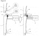
- FIG. 4 is a view schematically illustrating the electric power line connecting structure of the natural gas hydrate tank container loading system 10 enabling automated connection of the electric power line and the boil-off gas pipe according to the present invention, that is, FIG. 4 illustrates a specific configuration of part A indicated by a dotted line in FIG. 2 .
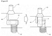
- FIG. 5 is a view schematically illustrating a specific configuration of the electric power line connecting structure of the natural gas hydrate tank container loading system 10 enabling automated connection of the electric power line and the boil-off gas pipe according to the present invention which is illustrated in FIG. 4 .
- one end side of the electric power line is configured to protect an electrode in a plug by a sloped water proof hinge type plug 41, which is hingedly connected in a state of being inclined to prevent an electric leakage caused by an inflow of rainwater or the like at normal times, and a compressive spring 42 installed below the sloped waterproof hinge type plug 41, and the other end side of the electric power line is configured to have a socket 43 coupled to the electrode of the sloped waterproof hinge type plug 41 and a pressing foot 44 for pressing the sloped waterproof hinge type plug 41 and to be fixed in the vicinity of upper and lower ends of the containers.
- connecting structures are configured at both end sides of the electric power line 15, and as a result, as illustrated in FIGS. 4 and 5 , when the upper gas hydrate tank container is stacked in the vertical direction, the electrode is exposed as the pressing foot 44 presses the sloped waterproof hinge type plug 41 and the sloped waterproof hinge type plug 41 is inserted into the socket 43 of the upper electric power line, such that the sloped waterproof hinge type plug 41 and the socket 43 are automatically coupled to each other, and when the sloped waterproof hinge type plug 41 and the socket 43 are separated from each other when removing the upper container, the sloped waterproof hinge type plug 41 automatically returns back to the original state by the compressive spring 42.
- the connecting structures are formed at both end sides of the electric power line as illustrated in FIGS. 4 and 5 , and as a result, it is possible to automatically perform operations of connecting and disconnecting the electric power line just by loading and unloading the containers.
- FIG. 6 is a view schematically illustrating the boil-off gas pipe connecting structure of the natural gas hydrate tank container loading system 10 enabling automated connection of the electric power line and the boil-off gas pipe according to the present invention, that is, FIG. 6 illustrates a specific configuration of part B indicated by a dotted line in FIG. 2 .
- the boil-off gas pipe connecting structure of the natural gas hydrate tank container loading system enabling automated connection of the electric power line and the boil-off gas pipe is configured such that a conical or spherical valve opening and closing protrusion 61 is formed at one end side of the boil-off gas pipe, and a compressive spring 62 is installed at a lower side of the valve opening and closing protrusion 61, and as a result, the valve opening and closing protrusion 61 is opened by being pressed downward, and the valve opening and closing protrusion 61 is closed when pressure is eliminated
- the boil-off gas pipe connecting structure is configured such that a connector 63, which is coupled to the valve opening and closing protrusion 61, is installed at the other end side of the boil-off gas pipe, and separate fixing means 64 are fixed to upper and lower end portions of the containers, respectively, thereby forming a connection valve which are automatically opened as the valve opening and closing protrusion 61 and the
- valve opening and closing protrusion 61 of the lower container is automatically coupled to the connector 63 of the upper container as the valve opening and closing protrusion 61 of the lower container is inserted into the connector 63 of the upper container, and the valve opening and closing protrusion 61 is automatically opened as the compressive spring 62 is pressed by a load of the container, and when the upper container is removed, the valve opening and closing protrusion 61 is closed as the valve opening and closing protrusion 61 automatically returns back to the original state by the compressive spring 62.
- the connecting structures are configured at both end sides of the boil-off gas pipe as illustrated in FIG. 6 , and as a result, it is possible to automatically perform operations of connecting and disconnecting the boil-off gas pipe just by loading and unloading the containers.
- the refrigerator is operated by charging the battery with electric power generated by operating the electric generator by using boil-off gas (BOG) and electrical energy collected by the photovoltaic array 21, such that it is possible to ensure electric power sufficient to operate the refrigerator for maintaining phase equilibrium of the natural gas hydrate without being supplied with separate electric power, transport the natural gas hydrate to a long distance, solve problems of fire or environmental pollution caused by a discharge of boil-off gas, and more quickly and easily perform the operations of loading and unloading the natural gas hydrate tank containers by automatically performing the operation of connecting the electric power line and the pipe which is performed manually in the related art.
- BOG boil-off gas
- the natural gas hydrate tank container loading system enabling automated connection of the electric power line and the boil-off gas pipe according to the present invention may be implemented.
- the natural gas hydrate tank container loading system enabling automated connection of the electric power line and the boil-off gas pipe
- the natural gas hydrate tank container loading system enabling automated connection of the electric power line and the boil-off gas pipe which is configured to automatically connecting the electric power line and connecting the pipe by simultaneously stacking the respective natural gas hydrate tank container, thereby solving problems of transportation methods using the natural gas hydrate tank containers in the related art in that the operation of connecting the electric power line to the refrigerator and the operation of connecting the pipe for discharging boil-off gas are manually and individually performed after stacking the respective natural gas hydrate tank containers, which causes an inconvenience.
Landscapes
- Engineering & Computer Science (AREA)
- Mechanical Engineering (AREA)
- General Engineering & Computer Science (AREA)
- Chemical & Material Sciences (AREA)
- Combustion & Propulsion (AREA)
- Ocean & Marine Engineering (AREA)
- Power Engineering (AREA)
- Physics & Mathematics (AREA)
- Fluid Mechanics (AREA)
- Filling Or Discharging Of Gas Storage Vessels (AREA)
Description
- The present invention relates to a loading system for transporting natural gas hydrate, and more particularly, to a natural gas hydrate tank container loading system which enables automated connection of an electric power line and a boil-off gas pipe, may stack and transport a plurality of natural gas hydrate tank containers for transporting the natural gas hydrate, and may automatically connect the electric power line only by stacking the respective containers without manually and individually performing, unlike the related art, connection of the electric power line for supplying electric power to a refrigerator for inhibiting the occurrence of boil-off gas (BOG) which naturally occurs in the respective natural gas hydrate tank containers during transportation of the natural gas hydrate.
- In addition, the present invention relates to the natural gas hydrate tank container loading system configured as described above, which enables automated connection of the electric power line and the boil-off gas pipe, and may automatically connect the pipe only by stacking the respective containers without manually and individually performing, unlike the related art, connection of the boil-off gas pipe for discharging the boil-off gas BOG generated in the respective containers.
- In general, hydrate is a solid substance in the form of ice including water molecules and gas molecules, and the hydrate is created as water and gas molecules come into contact with each other under predetermined pressure and a predetermined temperature. The hydrate is dissociated into water and gas molecules by changing pressure or a temperature, and the hydrate has high gas concentration because the hydrate has a crystal structure in which gas molecules are disposed in spaces made by water molecules, and as a result, the hydrate attracts attention as a new means for transporting and storing natural gas which is substituted for LNG.
- That is, it has been known that because the natural gas hydrate has a phase equilibrium (self-preservation) effect under a predetermined temperature and pressure condition, the natural gas hydrate may accommodate methane gas as much as up to 170 times a volume of the natural gas hydrate, and the phase equilibrium may be maintained when the natural gas hydrate is stored and transported at a temperature of about -20°C. Here, as examples in the related art for transporting the natural gas hydrate, for example, Korean Patent No.
10-0840059 10-1149498 - Further, as another example in the related art for transporting the natural gas hydrate, for example, Korean Patent No.
10-1262647 10-2014-0065588 - Various technologies for loading and transporting the natural gas hydrate have been presented in the related art as described above, but the natural gas hydrate transportation method in the related art has the following problems.
- That is, because boil-off gas (BOG) is partially generated even in a case in which phase equilibrium of the natural gas hydrate is maintained, the boil-off gas causes an increase in pressure in a transport container such as a tank container, and the amount of generated boil-off gas may be rapidly increased in a case in which a predetermined temperature and pressure condition cannot be satisfied due to damage or a breakdown of the transport container such as the tank container.
- Therefore, to minimize the amount of generated boil-off gas and maintain a phase equilibrium condition in the transport container such as the tank container, a refrigerator is installed and operated in the transport container such as the tank container in the related art.
- However, in general, there is a practical limitation in connecting electric power lines individually to the transport container such as the tank container, which loads and transports the natural gas hydrate with several thousands of TEU (Twenty-foot (6.1m) Equivalent Unit), and operating the refrigerator, and as a result, there is a problem in that to transport a large number of transport containers such as the tank container to a long distance by using the existing ships such as a container ship, it is necessary to maintain an appropriate temperature and pressure condition for maintaining phase equilibrium and to manage boil-off gas (BOG) which occurs naturally.
- In more detail, because the transport container such as the tank container is an adiabatic compression container, it is not greatly necessary to supply a heat quantity by the refrigerator in a case in which a transportation distance is short, but in a case in which a transportation distance becomes long, it is necessary to adjust a temperature condition for phase equilibrium by means of the refrigerator and the like because it may be difficult to maintain a temperature and pressure required for phase equilibrium of the adiabatic compression container over time.
- In addition, it is necessary to improve a pressure resistance capacity of the transport container in order to prevent the occurrence of a risk that pressure in the transport container such as the tank container is excessively increased due to the boil-off gas (BOG) and the transport container is damaged, but the improvement of the pressure resistance capacity of the transport container causes a problem of a decrease in the amount of loaded natural gas hydrate caused by a limitation in weight for each unit tank container because of an increase in load of the transport container itself, and a problem of an increase in transport container manufacturing costs.
- Further, in a case in which the boil-off gas is discharged to the outside of the transport container such as the tank container in order to prevent an increase in internal pressure, there is a problem of the occurrence of fire caused by lightning, friction, or spark, or a problem of environmental pollution.
- Furthermore, in the related art, an operation of connecting the electric power line to the refrigerator and an operation of connecting a pipe for discharging boil-off gas need to be manually and individually performed after stacking the respective natural gas hydrate tank containers during transportation of the natural gas hydrate, and as a result, there is a problem in that the operations of connecting the electric power line and the pipe are very inconvenient and require a large amount of time.
- Therefore, to solve the problems of the transportation method using the natural gas hydrate tank container in the related art, it is preferred to provide a natural gas hydrate tank container loading system which has a new configuration, may stack and transport a plurality of transport containers such as the tank container without excessively remodeling the existing ship such as a container ship or incurring costs, may stably supply electric power to the refrigerator for maintaining phase equilibrium of the respective transport containers during transportation with a simple configuration and low costs, and may effectively treat boil-off gas generated in the respective transport containers without discharging the boil-off gas to the outside, but an apparatus or a method, which meets all of the requirements, is not yet provided.
- In addition, to solve the problems of a transportation method using the natural gas hydrate tank containers in the related art in that the operation of connecting the electric power line to the refrigerator and the operation of connecting the pipe for discharging boil-off gas need to be manually and individually performed after stacking the containers, which causes an inconvenience, it is preferred to provide an electric power line and pipe connecting structure for a natural gas hydrate tank container loading system which has a new configuration, and may automatically connect the electric power line and automatically connect the pipe by simultaneously stacking the respective containers, but an apparatus or a method, which meets all of the requirements, is not yet provided.
- The present invention has been made in an effort to solve the aforementioned problems in the related art, and an object of the present invention is to provide a natural gas hydrate tank container loading system which enables automated connection of an electric power line and a boil-off gas pipe, and may automatically connect the electric power line and automatically connect the pipe by simultaneously stacking respective natural gas hydrate tank containers, in order to solve problems of a transportation method using the natural gas hydrate tank container in the related art in that an operation of connecting the electric power line to a refrigerator for minimizing the amount of generated boil-off gas (BOG) and maintaining a phase equilibrium condition in the tank container and an operation of connecting the pipe for discharging the boil-off gas need to be manually and individually performed for transporting a large amount of natural gas hydrate to a long distance by using a ship, which causes an inconvenience.
- To achieve the aforementioned object, the present invention provides a natural gas hydrate tank container loading system enabling automated connection of an electric power line and a boil-off gas pipe, which solves problems of natural gas hydrate transportation methods in the related art in that an operation of connecting the electric power line to a refrigerator for maintaining a phase equilibrium condition in a natural gas hydrate tank container and an operation of connecting the pipe for discharging boil-off gas generated in the respective natural gas hydrate tank containers are manually and individually performed during long-distance transportation of natural gas hydrate, which causes an inconvenience, the natural gas hydrate tank container loading system comprising: a plurality of natural gas hydrate tank containers which is stacked in a vertical direction; a refrigerator which is installed at one side of each of the natural gas hydrate tank containers for maintaining phase equilibrium of natural gas hydrate stored in each of the natural gas hydrate tank containers; an electric power supply unit which is installed at an upper portion of an uppermost container among the plurality of the gas hydrate tank containers stacked in the vertical direction for supplying electric power for operating the respective refrigerators; an electric power line which is installed at one side of the natural gas hydrate tank container and includes a connecting structure formed to be engaged with both ends for supplying electric power produced by the electric power supply unit to the respective refrigerators; and a boil-off gas pipe which is installed at one side of the natural gas hydrate tank container and includes a connecting structure formed to be engaged with both ends for supplying boil-off gas generated from the respective natural gas hydrate tank containers to the electric power supply unit.
- Here, the loading system may further include: a sensor unit which includes a plurality of sensors including temperature and pressure sensors for detecting a current state including an internal temperature or pressure in the respective natural gas hydrate tank containers; and a control unit which controls operations of the refrigerator and the electric power supply unit and an overall operation of the loading system based on the state detected by the respective sensors of the sensor unit.
- In addition, the electric power supply unit may include a photovoltaic array which generates electric power by using sunlight, an electric generator which is operated by boil-off gas generated from the respective natural gas hydrate tank containers, a fuel tank which stores fuel to be supplied to the electric generator, a compressor which mixes fuel supplied from the fuel tank with boil-off gas generated from the natural gas hydrate tank container and supplies the mixed fuel and boil-off gas to the electric generator, a battery (rechargeable battery cells) which stores electrical energy generated by the photovoltaic array and the electric generator, a fuel safety device which prevents fire and explosion caused by a reverse flow during combustion of the boil-off gas, and a housing which accommodates the electric generator, the fuel tank, the compressor, the battery, and the fuel safety device, and the electric power supply unit may charge the battery by the electric generator operated by using the photovoltaic array and the boil-off gas (BOG), and may operate the refrigerator and the compressor by using electrical energy with which the battery is charged, such that phase equilibrium in the respective natural gas hydrate tank container is always maintained without being supplied with separate electric power.
- Further, the loading system may further include a display unit which displays the current state including an internal temperature and pressure in the respective natural gas hydrate tank containers which is detected by the sensor unit so that the current state is monitored from the outside, a communication unit which transmits the current state of the loading system to the outside, and a fire extinguisher which copes with fire.
- Further, the electric power line may be configured according to claim 5.
- In addition, the boil-off gas pipe may include: a conical or spherical valve opening and closing protrusion which is installed at one end side of the boil-off gas pipe so as to be opened by being pressed downward and closed when pressure is eliminated; a compressive spring which is installed at a lower side of the valve opening and closing protrusion; a connector which is installed at the other end side of the boil-off gas pipe so as to be coupled to the valve opening and closing protrusion; and a fixing means which fixes the valve opening and closing protrusion, the compressive spring, and the connector to upper and lower ends of the natural gas hydrate tank container, respectively, such that a connection valve, which is automatically opened as the valve opening and closing protrusion and the connector come into contact with each other when stacking the natural gas hydrate tank containers, is formed, and when the upper gas hydrate tank container is stacked in the vertical direction, the valve opening and closing protrusion of the lower gas hydrate tank container is automatically coupled to the connector of the upper gas hydrate tank container as the valve opening and closing protrusion of the lower gas hydrate tank container is inserted into the connector of the upper gas hydrate tank container, the valve opening and closing protrusion is automatically opened as the compressive spring is pressed by a load of the upper gas hydrate tank container, and when the upper container is removed, the valve opening and closing protrusion is closed as the valve opening and closing protrusion automatically returns back to the original state by the compressive spring, such that operations of connecting and disconnecting the boil-off gas pipe are automatically performed just by loading and unloading the gas hydrate tank containers.
- In addition, the present invention provides a natural gas hydrate transportation ship comprising the natural gas hydrate tank container loading system enabling automated connection of a boil-off gas pipe.
- Further, the present invention provides a natural gas hydrate transportation method configured to transport natural gas hydrate by using the natural gas hydrate tank container loading system enabling automated connection of a boil-off gas pipe.
- According to the present invention as described above, there is provided the natural gas hydrate tank container loading system which enables automated connection of the electric power line and the boil-off gas pipe, and may automatically connect the electric power line and automatically connect the pipe by simultaneously stacking respective natural gas hydrate tank containers, thereby solving the problems of the transportation methods using the natural gas hydrate tank container in the related art in that the operation of connecting the electric power line to the refrigerator and the operation of connecting the pipe for discharging boil-off gas need to be manually and individually performed after stacking the respective natural gas hydrate tank containers, which causes an inconvenience.
-
-
FIG. 1 is a view schematically illustrating an entire configuration of a natural gas hydrate tank container loading system enabling automated connection of an electric power line and a boil-off gas pipe according to an exemplary embodiment of the present invention. -
FIG. 2 is a view schematically illustrating a specific configuration of an electric power supply unit of the natural gas hydrate tank container loading system enabling automated connection of the electric power line and the boil-off gas pipe according to the exemplary embodiment of the present invention which is illustrated inFIG. 1 . -
FIG. 3 is a view illustrating an entire configuration of the natural gas hydrate tank container loading system enabling automated connection of the electric power line and the boil-off gas pipe according to the exemplary embodiment of the present invention. -
FIG. 4 is a view schematically illustrating an electric power line connecting structure of the natural gas hydrate tank container loading system enabling automated connection of the electric power line and the boil-off gas pipe according to the present invention. -
FIG. 5 is a view schematically illustrating a specific configuration of the electric power line connecting structure of the natural gas hydrate tank container loading system enabling automated connection of the electric power line and the boil-off gas pipe according to the present invention which is illustrated inFIG. 4 . -
FIG. 6 is a view schematically illustrating a boil-off gas pipe connecting structure of the natural gas hydrate tank container loading system enabling automated connection of the electric power line and the boil-off gas pipe according to the present invention. - Hereinafter, a specific exemplary embodiment of a natural gas hydrate tank container loading system enabling automated connection of an electric power line and a boil-off gas pipe according to the present invention will be described with reference to the accompanying drawings.
- Here, it is noted that the following description is just one exemplary embodiment for implementing the present invention, and the present invention is not limited only to the contents of the exemplary embodiment to be described below.
- In addition, it is noted that in the description of the exemplary embodiment of the present invention, descriptions of parts, which are determined as being identical or similar to parts in the related art or being easily understood and implemented by those skill in the art, will be omitted for briefly describing the present invention.
- That is, as described below, the present invention relates to a natural gas hydrate tank container loading system which enables automated connection of an electric power line and a boil-off gas pipe, and may automatically connect the electric power line and automatically connect the pipe by simultaneously stacking respective natural gas hydrate tank containers, in order to solve problems of a transportation method using the natural gas hydrate tank container in the related art in that an operation of connecting the electric power line to a refrigerator for minimizing the amount of generated boil-off gas (BOG) and maintaining a phase equilibrium condition in the tank container and an operation of connecting the pipe for discharging the boil-off gas need to be manually and individually performed for transporting a large amount of natural gas hydrate to a long distance by using a ship, which causes an inconvenience.
- Next, a specific exemplary embodiment of the natural gas hydrate tank container loading system enabling automated connection of the electric power line and the boil-off gas pipe according to the present invention, which is configured as described above, will be described with reference to the drawings.
- First, referring to
FIG. 1, FIG. 1 is a view schematically illustrating an entire configuration of the natural gas hydrate tank container loading system enabling automated connection of the electric power line and the boil-off gas pipe according to the exemplary embodiment of the present invention. - As illustrated in
FIG. 1 , a natural gas hydrate tankcontainer loading system 10 enabling automated connection of an electric power line and a boil-off gas pipe according to the exemplary embodiment of the present invention roughly includes a plurality of natural gashydrate tank containers 11 which is stacked to be stacked in a vertical direction, arefrigerator 12 which is installed at one side of each of the natural gas hydrate tank containers in order to maintain phase equilibrium of natural gas hydrate stored in each of the stacked natural gas hydrate tank containers, an electricpower supply unit 13 which is installed at an upper end of the natural gashydrate tank container 11, and includes an electric generator and a battery operated by using a photovoltaic array and boil-off gas (BOG) for supplying electric power for operating therespective refrigerators 12, asensor unit 14 which includes various types of sensors such as temperature and pressure sensors for detecting a state such as an internal temperature or pressure in the respective natural gas hydrate tank containers, anelectric power line 15 which is installed at one side of the natural gashydrate tank container 11, and includes a connecting structure formed to be engaged with both ends for supplying electric power produced by the electricpower supply unit 13 to therefrigerator 12 of each of the natural gas hydrate tank containers, and a control unit (not illustrated) which includes a connecting structure formed to be engaged with both ends for supplying boil-off gas generated from the respective natural gas hydrate tank containers to an electric generator installed in the electricpower supply unit 13 together with fuel, and controls operations of the refrigerator and the electricpower supply unit 13 and an overall operation of theloading system 10 based on the state detected by the respective sensors of thesensor unit 14 and a boil-off gas pipe 16 installed at one side of the natural gashydrate tank container 11. - Further, although not illustrated, the
loading system 10 may further include a display unit which displays the current state such as an internal temperature, and pressure in the respective natural gas hydrate tank containers which is detected by thesensor unit 14 so that the current state may be monitored from the outside, a communication unit which transmits the state of theloading system 10 to the outside, and a fire extinguisher which copes with fire that may occur at the electric generator operated by using the boil-off gas, and the refrigerator for maintaining the phase equilibrium in the natural gas hydrate tank container. - That is, as illustrated in
FIG. 1 , the natural gas hydrate tankcontainer loading system 10 enabling automated connection of the electric power line and the boil-off gas pipe according to the exemplary embodiment of the present invention is characterized by charging the battery by collecting electric power from the electric generator operated by using the boil-off gas (BOG) and the photovoltaic array installed to an uppermost container among the gas hydrate transport containers such as tank containers stacked in the vertical direction, and operating the refrigerator and a compressor for maintaining a phase equilibrium condition of the natural gas hydrate by using the electrical energy with which the battery is charged, and in this case, the operations of connecting theelectric power line 15 and connecting the boil-offgas pipe 16 may be automatically performed by using theelectric power line 15 and the boil-offgas pipe 16 having the connecting structures formed at both ends as described below without having to manually and individually performing the operations of connecting theelectric power line 15 and connecting the boil-offgas pipe 16 unlike the related art. - In more detail, referring to
FIG. 2, FIG. 2 is a view schematically illustrating a specific configuration of the electricpower supply unit 13 of the natural gas hydrate tankcontainer loading system 10 enabling automated connection of the electric power line and the boil-off gas pipe according to the exemplary embodiment of the present invention which is illustrated inFIG. 1 . - As illustrated in
FIG. 2 , the electricpower supply unit 13 includes aphotovoltaic array 21 which generates electric power by using sunlight, and a battery (rechargeable battery cells) 22 which stores the electrical energy generated by thephotovoltaic array 21, such that the electricpower supply unit 13 is configured to operate therefrigerators 12 for maintaining phase equilibrium in the respective natural gas hydrate tank containers without being supplied with separate electric power. - Here, for example, the electric
power supply unit 13 has a separateelectric generator 23, acompressor 24, and afuel tank 25 which are provided in ahousing 26, as illustrated inFIG. 2 , so as to charge the embeddedbattery 22 in order to prepare for a situation in which an insufficient amount of electric power is generated by thephotovoltaic array 21 due to a weather condition or the like. - In more detail, in addition to the operation of generating electric power by using the
photovoltaic array 21, the electricpower supply unit 13 is configured such that valves for discharging the boil-off gas (BOG) are installed to the natural gas hydrate tank containers, respectively, mixture gas is produced by mixing the boil-off gas (BOG) generated from the respective natural gas hydrate tank containers with fuel stored in thefuel tank 25 through the boil-off gas pipe 16, and theelectric generator 23 is operated by supplying the mixture gas produced as described above to theelectric generator 23 through thecompressor 23, and as a result, it is possible to always ensure electric power sufficient to operate the respective refrigerators regardless of external factors such as a weather condition, and it is possible to treat the boil-off gas (BOG) generated from the respective natural gas hydrate tank containers in the natural gas hydrate tankcontainer loading system 10 without discharging the boil-off gas to the outside, thereby eliminating a problem of environmental pollution or fire caused by a discharge of the boil-off gas (BOG) unlike the related art. - That is, referring to
FIG. 3, FIG. 3 is a view illustrating a concept of an entire configuration of the natural gas hydrate tankcontainer loading system 10 enabling automated connection of the electric power line and the boil-off gas pipe according to the exemplary embodiment of the present invention which is configured as described above. - Here, as illustrated in
FIGS. 2 and3 , the electricpower supply unit 13 includes a temperature sensor, a detonation arrester, a quick closing valve, and a flashback pressure valve, and may further include afuel safety device 27 which is included in thehousing 26 and configured to prevent fire and explosion caused by a reverse flow during combustion of the boil-off gas (BOG). - Therefore, the natural gas hydrate tank
container loading system 10 enabling automated connection of the electric power line and the boil-off gas pipe according to the present invention may be implemented as illustrated inFIGS. 1 to 3 , and as a result, it is possible to operate the refrigerator by charging the battery with electrical energy collected by thephotovoltaic array 21, and thus to operate the refrigerator for maintaining phase equilibrium of the natural gas hydrate without being supplied with separate electric power, and in addition, the battery is also charged with electric power generated by operating the electric generator by using the boil-off gas BOG, and as a result, it is possible to ensure electric power sufficient to operate the refrigerator even in a case in which a weather condition is worsen which is a drawback in photovoltaic generation, such that it is possible to transport the natural gas hydrate to a long distance without having a separate electric power supply device, and thus to solve a problem of fire or environmental pollution caused by a discharge of the boil-off gas. - In addition, the natural gas hydrate tank
container loading system 10 enabling automated connection of the electric power line and the boil-off gas pipe according to the exemplary embodiment of the present invention, which is configured as described above, may include an electric power line connecting structure which automatically connects the electric power line which is connected manually in the related art, and a boil-off gas pipe connecting structure which automatically connects a boil-off gas capturing pipe which is connected manually in the related art, as described below. - Next, specific configurations of the electric power line connecting structure and the boil-off gas pipe connecting structure, which are configured to automatically perform the connection operations, which are performed manually in the related art, will be described with reference to
FIGS. 4 to 6 . - First, referring to
FIG. 4, FIG. 4 is a view schematically illustrating the electric power line connecting structure of the natural gas hydrate tankcontainer loading system 10 enabling automated connection of the electric power line and the boil-off gas pipe according to the present invention, that is,FIG. 4 illustrates a specific configuration of part A indicated by a dotted line inFIG. 2 . - In addition, referring to
FIG. 5, FIG. 5 is a view schematically illustrating a specific configuration of the electric power line connecting structure of the natural gas hydrate tankcontainer loading system 10 enabling automated connection of the electric power line and the boil-off gas pipe according to the present invention which is illustrated inFIG. 4 . - In more detail, as illustrated in
FIGS. 4 and5 , in the electric power line connecting structure of the natural gas hydrate tank container loading system enabling automated connection of the electric power line and the boil-off gas pipe according to the exemplary embodiment of the present invention, one end side of the electric power line is configured to protect an electrode in a plug by a sloped water proofhinge type plug 41, which is hingedly connected in a state of being inclined to prevent an electric leakage caused by an inflow of rainwater or the like at normal times, and acompressive spring 42 installed below the sloped waterproofhinge type plug 41, and the other end side of the electric power line is configured to have asocket 43 coupled to the electrode of the sloped waterproofhinge type plug 41 and apressing foot 44 for pressing the sloped waterproofhinge type plug 41 and to be fixed in the vicinity of upper and lower ends of the containers. - As described above, connecting structures are configured at both end sides of the
electric power line 15, and as a result, as illustrated inFIGS. 4 and5 , when the upper gas hydrate tank container is stacked in the vertical direction, the electrode is exposed as thepressing foot 44 presses the sloped waterproofhinge type plug 41 and the sloped waterproofhinge type plug 41 is inserted into thesocket 43 of the upper electric power line, such that the sloped waterproofhinge type plug 41 and thesocket 43 are automatically coupled to each other, and when the sloped waterproofhinge type plug 41 and thesocket 43 are separated from each other when removing the upper container, the sloped waterproofhinge type plug 41 automatically returns back to the original state by thecompressive spring 42. - Therefore, an operation of connecting the electric power line for operating the refrigerator is manually and individually performed in the related art, but according to the electric power line connecting structure of the natural gas hydrate tank container loading system enabling automated connection of the electric power line and the boil-off gas pipe according to the exemplary embodiment of the present invention, the connecting structures are formed at both end sides of the electric power line as illustrated in
FIGS. 4 and5 , and as a result, it is possible to automatically perform operations of connecting and disconnecting the electric power line just by loading and unloading the containers. - Next, referring to
FIG. 6, FIG. 6 is a view schematically illustrating the boil-off gas pipe connecting structure of the natural gas hydrate tankcontainer loading system 10 enabling automated connection of the electric power line and the boil-off gas pipe according to the present invention, that is,FIG. 6 illustrates a specific configuration of part B indicated by a dotted line inFIG. 2 . - In more detail, as illustrated in
FIG. 6 , the boil-off gas pipe connecting structure of the natural gas hydrate tank container loading system enabling automated connection of the electric power line and the boil-off gas pipe according to the exemplary embodiment of the present invention is configured such that a conical or spherical valve opening and closingprotrusion 61 is formed at one end side of the boil-off gas pipe, and acompressive spring 62 is installed at a lower side of the valve opening and closingprotrusion 61, and as a result, the valve opening and closingprotrusion 61 is opened by being pressed downward, and the valve opening and closingprotrusion 61 is closed when pressure is eliminated, and the boil-off gas pipe connecting structure is configured such that aconnector 63, which is coupled to the valve opening and closingprotrusion 61, is installed at the other end side of the boil-off gas pipe, and separate fixing means 64 are fixed to upper and lower end portions of the containers, respectively, thereby forming a connection valve which are automatically opened as the valve opening and closingprotrusion 61 and theconnector 63 come into contact with each other when stacking the containers. - With the aforementioned configuration, as illustrated in
FIG. 6 , when the upper gas hydrate tank container is stacked in the vertical direction, the valve opening and closingprotrusion 61 of the lower container is automatically coupled to theconnector 63 of the upper container as the valve opening and closingprotrusion 61 of the lower container is inserted into theconnector 63 of the upper container, and the valve opening and closingprotrusion 61 is automatically opened as thecompressive spring 62 is pressed by a load of the container, and when the upper container is removed, the valve opening and closingprotrusion 61 is closed as the valve opening and closingprotrusion 61 automatically returns back to the original state by thecompressive spring 62. - That is, an operation of connecting the pipe for discharging boil-off gas is manually and individually performed in the related art, but according to the boil-off gas pipe connecting structure of the natural gas hydrate tank container loading system enabling automated connection of the electric power line and the boil-off gas pipe according to the exemplary embodiment of the present invention, the connecting structures are configured at both end sides of the boil-off gas pipe as illustrated in
FIG. 6 , and as a result, it is possible to automatically perform operations of connecting and disconnecting the boil-off gas pipe just by loading and unloading the containers. - According to the configuration of the natural gas hydrate tank
container loading system 10 enabling automated connection of the electric power line and the boil-off gas pipe according to the exemplary embodiment of the present invention, the refrigerator is operated by charging the battery with electric power generated by operating the electric generator by using boil-off gas (BOG) and electrical energy collected by thephotovoltaic array 21, such that it is possible to ensure electric power sufficient to operate the refrigerator for maintaining phase equilibrium of the natural gas hydrate without being supplied with separate electric power, transport the natural gas hydrate to a long distance, solve problems of fire or environmental pollution caused by a discharge of boil-off gas, and more quickly and easily perform the operations of loading and unloading the natural gas hydrate tank containers by automatically performing the operation of connecting the electric power line and the pipe which is performed manually in the related art. - Therefore, as described above, the natural gas hydrate tank container loading system enabling automated connection of the electric power line and the boil-off gas pipe according to the present invention may be implemented.
- In addition, according to the present invention which implements the natural gas hydrate tank container loading system enabling automated connection of the electric power line and the boil-off gas pipe, there is provided the natural gas hydrate tank container loading system enabling automated connection of the electric power line and the boil-off gas pipe which is configured to automatically connecting the electric power line and connecting the pipe by simultaneously stacking the respective natural gas hydrate tank container, thereby solving problems of transportation methods using the natural gas hydrate tank containers in the related art in that the operation of connecting the electric power line to the refrigerator and the operation of connecting the pipe for discharging boil-off gas are manually and individually performed after stacking the respective natural gas hydrate tank containers, which causes an inconvenience.
- While the detailed description of the natural gas hydrate tank container loading system enabling automated connection of the electric power line and the boil-off gas pipe according to the present invention has been described above through the exemplary embodiments of the present invention, the present invention is not limited only to the contents of the exemplary embodiment, and thus the present invention may of course be variously modified, changed, combined, and substituted in accordance with design necessity and other various factors by those skilled in the art to which the present invention pertains, while still falling within the subject-matter of the claims.
-
- 10:
- natural gas hydrate tank container loading system
- 11:
- natural gas hydrate tank container
- 12:
- refrigerator
- 13:
- electric power supply unit
- 14:
- sensor unit
- 15:
- electric power line
- 16:
- boil-off gas pipe
- 21:
- photovoltaic array
- 22:
- battery
- 23:
- electric generator
- 24:
- compressor
- 25:
- fuel tank
- 26:
- housing
- 27:
- fuel safety device
- 41:
- sloped waterproof hinge type plug
- 42:
- compressive spring
- 43:
- socket
- 44:
- pressing foot
- 61:
- valve opening and closing protrusion
- 62:
- compressive spring
- 63:
- connector
- 64:
- fixing means
Claims (8)
- A natural gas hydrate tank container loading system (10) enabling automated connection of an electric power line (15) and a boil-off gas pipe (16), which solves problems of natural gas hydrate transportation methods in the related art in that an operation of connecting the electric power line (15) to a refrigerator (12) for maintaining a phase equilibrium condition in a natural gas hydrate tank container (11) and an operation of connecting the pipe (16) for discharging boil-off gas (BOG) generated in the respective natural gas hydrate tank containers (11) are manually and individually performed during long-distance transportation of natural gas hydrate, which causes an inconvenience, the natural gas hydrate tank container loading system (10) comprising:- a plurality of natural gas hydrate tank containers (11) which are stacked in a vertical direction; and- a refrigerator (12) which is installed at one side of each of the natural gas hydrate tank containers (11) for maintaining phase equilibrium of natural gas hydrate stored in each of the natural gas hydrate tank containers (11),characterized in that
the system further comprises:- an electric power supply unit (13) which is installed at an upper portion of an uppermost container (11) among the plurality of the gas hydrate tank containers (11) stacked in the vertical direction for supplying electric power for operating the respective refrigerators (12);an electric power line (15) which is installed at one side of the natural gas hydrate tank container (11) and includes an electric power line connecting structure formed to be engaged with both ends for supplying electric power produced by the electric power supply unit (13) to the respective refrigerators (12); and
a boil-off gas pipe (16) which is installed at one side of the natural gas hydrate tank container (11) and includes a boil-off gas pipe connecting structure formed to be engaged with both ends for supplying boil-off gas (BOG) generated from the respective natural gas hydrate tank containers (11) to the electric power supply unit (13). - The natural gas hydrate tank container loading system (10) of claim 1, wherein the loading system (10) further includes:- a sensor unit (14) which includes a plurality of sensors including temperature and pressure sensors for detecting a current state including an internal temperature or pressure in the respective natural gas hydrate tank containers (11); and- a control unit which controls operations of the refrigerator (12) and the electric power supply unit (13) and an overall operation of the loading system (10) based on the state detected by the respective sensors of the sensor unit (14).
- The natural gas hydrate tank container loading system (10) of claim 2, wherein the loading system (10) further includes:- a display unit which displays the current state including an internal temperature and pressure in the respective natural gas hydrate tank containers (11) which is detected by the sensor unit (14) so that the current state is monitored from the outside;- a communication unit which transmits the current state of the loading system (10) to the outside; and- a fire extinguisher which copes with fire.
- The natural gas hydrate tank container loading system (10) of claim 1, wherein the electric power supply unit (13) includes:- a photovoltaic array (21) which generates electric power by using sunlight;- an electric generator (23) which is operated by boil-off gas (BOG) generated from the respective natural gas hydrate tank containers (11);- a fuel tank (25) which stores fuel to be supplied to the electric generator (23);- a compressor (24) which mixes fuel supplied from the fuel tank (25) with boil-off gas (BOG) generated from the natural gas hydrate tank container (11) and supplies the mixed fuel and boil-off gas (BOG) to the electric generator (23);- a battery (22) (rechargeable battery cells) which stores electrical energy generated by the photovoltaic array (21) and the electric generator (23);- a fuel safety device (27) which prevents fire and explosion caused by a reverse flow during combustion of the boil-off gas (BOG); and- a housing (26) which accommodates the electric generator (23), the fuel tank (25), the compressor (24), the battery (22), and the fuel safety device (27),wherein the electric power supply unit (13) charges the battery (22) by the electric generator (23) operated by using the photovoltaic array (21) and the boil-off gas (BOG), and operates the refrigerator (12) and the compressor (24) by using electrical energy with which the battery (22) is charged, such that phase equilibrium in the respective natural gas hydrate tank container (11) is always maintained without being supplied with separate electric power.
- The natural gas hydrate tank container loading system (10) of claim 1, wherein the electric power line connecting structure of the electric power line (15) includes:- a sloped water proof hinge type plug (41) which is installed at one end side of the electric power line (15), which is hingedly connected in a state of being inclined in order to prevent an electric leakage caused by an inflow of foreign substances including rainwater and protect an electrode in the sloped water proof hinge type plug (41);- a compressive spring (42) installed at a lower side of the sloped water proof hinge type plug (41);- a socket (43) which is installed at the other end side of the electric power line (15), which is able to be coupled to the electrode in the sloped waterproof hinge type plug (41); and- a pressing foot (44) for pressing the sloped waterproof hinge type plug (41), which is formed at the other end side of the electric power line (15), such that when the upper gas hydrate tank container (11) is stacked in the vertical direction, the electrode is exposed as the pressing foot (44) presses the sloped waterproof hinge type plug (41) and the sloped waterproof hinge type plug (41) is inserted into the socket (43), such that the sloped waterproof hinge type plug (41) and the socket (43) are automatically coupled to each other, and when removing the upper gas hydrate tank container (11), the sloped waterproof hinge type plug (41) and the socket (43) are separated from each other, the sloped waterproof hinge type plug (41) automatically returns back to the original state by the compressive spring (42), such that operations of connecting and disconnecting the electric power line (15) is automatically performed just by loading and unloading the gas hydrate tank containers (11).
- The natural gas hydrate tank container loading system (10) of claim 1, wherein the boil-off gas pipe connecting structure of the boil-off gas pipe (16) includes:- a valve opening and closing protrusion (61) which is installed at one end side of the boil-off gas pipe (16) so as to be opened by being pressed downward and closed when pressure is eliminated;- a compressive spring (62) which is installed at a lower side of the valve opening and closing protrusion (61);- a connector (63) which is installed at the other end side of the boil-off gas pipe (16) so as to be coupled to the valve opening and closing protrusion (61); and- a fixing means (64) which fixes the valve opening and closing protrusion (61), the compressive spring (62), and the connector (63) to upper and lower ends of the natural gas hydrate tank container (11), respectively, such that a connection valve, which is automatically opened as the valve opening and closing protrusion (61) and the connector (63) come into contact with each other when stacking the natural gas hydrate tank containers (11), is formed, and when the upper gas hydrate tank container (11) is stacked in the vertical direction, the valve opening and closing protrusion (61) of the lower gas hydrate tank container (11) is automatically coupled to the connector (63) of the upper gas hydrate tank container (11) as the valve opening and closing protrusion (61) of the lower gas hydrate tank container (11) is inserted into the connector (63) of the upper gas hydrate tank container (11), the valve opening and closing protrusion (61) is automatically opened as the compressive spring (62) is pressed by a load of the upper gas hydrate tank container (11), and when the upper container (11) is removed, the valve opening and closing protrusion (61) is closed as the valve opening and closing protrusion (61) automatically returns back to the original state by the compressive spring (62), such that operations of connecting and disconnecting the boil-off gas pipe (16) are automatically performed just by loading and unloading the gas hydrate tank containers (11).
- A natural gas hydrate transportation ship comprising the natural gas hydrate tank container loading system (10) enabling automated connection of a boil-off gas pipe (16) according to any one of claims 1 to 6.
- A natural gas hydrate transportation method configured to transport natural gas hydrate by using the natural gas hydrate tank container loading system enabling automated connection of a boil-off gas pipe according to any one of the claims 1 to 6.
Applications Claiming Priority (2)
| Application Number | Priority Date | Filing Date | Title |
|---|---|---|---|
| KR1020140167302A KR101659873B1 (en) | 2014-11-27 | 2014-11-27 | Natural gas hydrate tank containers stack system capable of connecting power cable and boiled off gas pipes automatically |
| PCT/KR2014/012447 WO2016085028A1 (en) | 2014-11-27 | 2014-12-17 | Natural gas hydrate tank container loading system enabling automated connection of electric power line and boil-off gas pipe |
Publications (3)
| Publication Number | Publication Date |
|---|---|
| EP3225530A1 EP3225530A1 (en) | 2017-10-04 |
| EP3225530A4 EP3225530A4 (en) | 2018-05-23 |
| EP3225530B1 true EP3225530B1 (en) | 2019-10-30 |
Family
ID=56074567
Family Applications (1)
| Application Number | Title | Priority Date | Filing Date |
|---|---|---|---|
| EP14906818.1A Active EP3225530B1 (en) | 2014-11-27 | 2014-12-17 | Natural gas hydrate tank container loading system enabling automated connection of electric power line and boil-off gas pipe |
Country Status (7)
| Country | Link |
|---|---|
| US (1) | US10138930B2 (en) |
| EP (1) | EP3225530B1 (en) |
| JP (1) | JP6329323B2 (en) |
| KR (1) | KR101659873B1 (en) |
| CN (1) | CN107074326B (en) |
| DK (1) | DK3225530T3 (en) |
| WO (1) | WO2016085028A1 (en) |
Families Citing this family (10)
| Publication number | Priority date | Publication date | Assignee | Title |
|---|---|---|---|---|
| CN109455424A (en) * | 2017-09-06 | 2019-03-12 | 青岛中集特种冷藏设备有限公司 | Container and container group with it |
| GB201719399D0 (en) * | 2017-11-22 | 2018-01-03 | Bennamann Services Ltd | Liquid methane storage and fuel delivery system |
| CN109404726A (en) * | 2018-12-14 | 2019-03-01 | 中交第二航务工程勘察设计院有限公司 | A kind of cryogenic liquid pot type container is released collection device |
| DE202018005860U1 (en) * | 2018-12-17 | 2020-03-19 | Tge Marine Gas Engineering Gmbh | Monitoring device |
| CN109882258B (en) * | 2019-03-15 | 2024-05-28 | 华南理工大学 | A device for generating electricity and outputting electricity in a high-pressure natural gas pipeline |
| JP7226366B2 (en) * | 2020-02-12 | 2023-02-21 | トヨタ自動車株式会社 | fuel storage device |
| KR102904573B1 (en) * | 2020-10-16 | 2025-12-24 | 삼성중공업 주식회사 | Boil-off gas operating system |
| JP2022152490A (en) * | 2021-03-29 | 2022-10-12 | 株式会社前川製作所 | Inhibition device and inhibition method |
| CN117446369A (en) | 2022-07-19 | 2024-01-26 | 烟台创为新能源科技股份有限公司 | A special container for battery transportation |
| JP2026068808A (en) * | 2024-10-11 | 2026-04-23 | 川崎重工業株式会社 | Gas fuel supply system |
Family Cites Families (22)
| Publication number | Priority date | Publication date | Assignee | Title |
|---|---|---|---|---|
| US4331129A (en) * | 1979-07-05 | 1982-05-25 | Columbia Gas System Service Corporation | Solar energy for LNG vaporization |
| TW359736B (en) * | 1997-06-20 | 1999-06-01 | Exxon Production Research Co | Systems for vehicular, land-based distribution of liquefied natural gas |
| DZ2528A1 (en) * | 1997-06-20 | 2003-02-01 | Exxon Production Research Co | Container for the storage of pressurized liquefied natural gas and a process for the transport of pressurized liquefied natural gas and natural gas treatment system to produce liquefied natural gas under pressure. |
| JP4145063B2 (en) * | 2002-03-29 | 2008-09-03 | 株式会社川崎造船 | Cargo hold cooler |
| CN1690503A (en) * | 2004-04-21 | 2005-11-02 | 中国科学院过程工程研究所 | A method integrating the preparation of natural gas hydrate, storage and transportation of natural gas and distribution |
| CN100346104C (en) * | 2004-04-21 | 2007-10-31 | 中国科学院过程工程研究所 | Integration barge for natural gas synthesized hydrate storage and long distance transportation |
| KR100840059B1 (en) | 2004-09-06 | 2008-06-19 | 현대중공업 주식회사 | Natural gas transportation |
| JP4263163B2 (en) * | 2004-11-29 | 2009-05-13 | 株式会社川崎造船 | Gas hydrate pellet storage device and storage method thereof |
| JP4866642B2 (en) * | 2006-03-30 | 2012-02-01 | 三井造船株式会社 | Pellet cooler in natural gas hydrate production plant |
| EP2160539B1 (en) * | 2007-03-02 | 2017-05-03 | Enersea Transport LLC | Apparatus and method for flowing compressed fluids into and out of containment |
| KR100941485B1 (en) * | 2009-03-27 | 2010-02-10 | 한국가스공사연구개발원 | United gashydrate formation, transportation and decomposition apparatus |
| CN101520130A (en) * | 2009-04-10 | 2009-09-02 | 中国石油大学(华东) | Hydrate storage and transportation device |
| JP5339522B2 (en) * | 2009-05-12 | 2013-11-13 | ジャパンマリンユナイテッド株式会社 | Liquefied gas storage system |
| KR101149498B1 (en) * | 2009-08-12 | 2012-05-29 | 삼성중공업 주식회사 | Natural gas hydrate container |
| US8866334B2 (en) * | 2010-03-02 | 2014-10-21 | Icr Turbine Engine Corporation | Dispatchable power from a renewable energy facility |
| US8727821B2 (en) * | 2010-05-07 | 2014-05-20 | Daewoo Shipbuilding & Marine Engineering Co., Ltd. | Apparatus and method for generating electricity in liquefied natural gas carrier |
| KR101701279B1 (en) * | 2010-08-10 | 2017-02-02 | 대우조선해양 주식회사 | container tank having solar power generating system |
| FR2985802B1 (en) * | 2012-01-17 | 2014-03-14 | Air Liquide | MODULAR ELEMENT FOR GAS DISTRIBUTION UNDER PRESSURE AND CORRESPONDING INSTALLATION |
| KR101262647B1 (en) | 2012-08-14 | 2013-05-08 | 주식회사에스티엑스종합기술원 | Natural gas hydrate loading device |
| KR101255547B1 (en) * | 2012-09-04 | 2013-04-17 | 한국해양과학기술원 | Container for hydrate pallet storage, shipping and regasfication and method in using same |
| KR20140065588A (en) | 2012-11-16 | 2014-05-30 | 에스티엑스조선해양 주식회사 | Apparatus and method unloading gas hydrate |
| CN103754152A (en) * | 2013-11-27 | 2014-04-30 | 张延红 | Transport vehicle for transporting combustible ice |
-
2014
- 2014-11-27 KR KR1020140167302A patent/KR101659873B1/en active Active
- 2014-12-17 JP JP2017527347A patent/JP6329323B2/en active Active
- 2014-12-17 CN CN201480082954.XA patent/CN107074326B/en active Active
- 2014-12-17 DK DK14906818T patent/DK3225530T3/en active
- 2014-12-17 WO PCT/KR2014/012447 patent/WO2016085028A1/en not_active Ceased
- 2014-12-17 US US15/521,119 patent/US10138930B2/en active Active
- 2014-12-17 EP EP14906818.1A patent/EP3225530B1/en active Active
Non-Patent Citations (1)
| Title |
|---|
| None * |
Also Published As
| Publication number | Publication date |
|---|---|
| EP3225530A1 (en) | 2017-10-04 |
| CN107074326B (en) | 2018-06-22 |
| CN107074326A (en) | 2017-08-18 |
| KR20160063702A (en) | 2016-06-07 |
| JP6329323B2 (en) | 2018-05-23 |
| US10138930B2 (en) | 2018-11-27 |
| DK3225530T3 (en) | 2019-12-09 |
| WO2016085028A1 (en) | 2016-06-02 |
| US20170356599A1 (en) | 2017-12-14 |
| KR101659873B1 (en) | 2016-09-27 |
| EP3225530A4 (en) | 2018-05-23 |
| JP2017534528A (en) | 2017-11-24 |
Similar Documents
| Publication | Publication Date | Title |
|---|---|---|
| EP3225535B1 (en) | Natural gas hydrate tank container loading system enabling self-powered power generation and boil-off gas treatment | |
| US10138930B2 (en) | Natural gas hydrate tank container loading system enabling automated connection of electric power line and boil-off gas pipe | |
| EP2489586B1 (en) | Floating structure with fuel tank for gas fuel | |
| RU2589811C2 (en) | Vessel for transportation of compressed gas | |
| KR101255547B1 (en) | Container for hydrate pallet storage, shipping and regasfication and method in using same | |
| US10629872B2 (en) | Autonomous under water power supply device | |
| CN105845956A (en) | Integral methanol reforming fuel cell system | |
| KR102069568B1 (en) | Apparatus for transferring electrolyte and safety system including the same | |
| EP4475281A1 (en) | Battery pack | |
| KR102305899B1 (en) | Apparatus for transferring electrolyte and safety system including the same | |
| Chatelier | Entering a new era for electrical vessel on inland waterways | |
| US20120249077A1 (en) | Battery system for electricity transport vessel | |
| KR102888591B1 (en) | Bunkering Vessel capable of charging multiple fuels | |
| KR20150143583A (en) | Improved system for treating and supplying natural gas comprising a circuit for heating the tank | |
| KR20130123749A (en) | Charge system for energy storage apparatus, vehicle for charge applied for it and method of charge for energy storage apparatus using the same | |
| KR101370179B1 (en) | Ship with rechargeable liquefied fuel gas storage tank | |
| US20230369679A1 (en) | Battery rack and energy storage system comprising same | |
| KR102352046B1 (en) | Method of supply for hydrogen fuel of the hydrogen fuel cell propulsion vessel | |
| CN209150798U (en) | A kind of Novel low power consumption power off in standby state of electric device | |
| FR3024291A1 (en) | ENERGY GENERATION SYSTEM COMPRISING A FUEL CELL AND RECHARGEABLE BATTERY AND METHODS USING SUCH A DEVICE | |
| CN216012997U (en) | Battery pressure-bearing testing device | |
| KR102921643B1 (en) | Apparatus for transferring explosive material | |
| KR20210015198A (en) | System for suppressing fire and floater with the system | |
| CZ30009U1 (en) | Modular L-CNG and LNG filling station | |
| KR20170057724A (en) | Ship |
Legal Events
| Date | Code | Title | Description |
|---|---|---|---|
| STAA | Information on the status of an ep patent application or granted ep patent |
Free format text: STATUS: THE INTERNATIONAL PUBLICATION HAS BEEN MADE |
|
| PUAI | Public reference made under article 153(3) epc to a published international application that has entered the european phase |
Free format text: ORIGINAL CODE: 0009012 |
|
| STAA | Information on the status of an ep patent application or granted ep patent |
Free format text: STATUS: REQUEST FOR EXAMINATION WAS MADE |
|
| 17P | Request for examination filed |
Effective date: 20170515 |
|
| AK | Designated contracting states |
Kind code of ref document: A1 Designated state(s): AL AT BE BG CH CY CZ DE DK EE ES FI FR GB GR HR HU IE IS IT LI LT LU LV MC MK MT NL NO PL PT RO RS SE SI SK SM TR |
|
| AX | Request for extension of the european patent |
Extension state: BA ME |
|
| DAX | Request for extension of the european patent (deleted) | ||
| A4 | Supplementary search report drawn up and despatched |
Effective date: 20180419 |
|
| RIC1 | Information provided on ipc code assigned before grant |
Ipc: H02S 10/00 20140101ALI20180413BHEP Ipc: B63J 3/00 20060101ALI20180413BHEP Ipc: F17C 13/08 20060101ALI20180413BHEP Ipc: F17C 1/00 20060101ALI20180413BHEP Ipc: F17C 13/12 20060101ALI20180413BHEP Ipc: B63B 25/04 20060101AFI20180413BHEP |
|
| STAA | Information on the status of an ep patent application or granted ep patent |
Free format text: STATUS: EXAMINATION IS IN PROGRESS |
|
| 17Q | First examination report despatched |
Effective date: 20190213 |
|
| GRAP | Despatch of communication of intention to grant a patent |
Free format text: ORIGINAL CODE: EPIDOSNIGR1 |
|
| STAA | Information on the status of an ep patent application or granted ep patent |
Free format text: STATUS: GRANT OF PATENT IS INTENDED |
|
| INTG | Intention to grant announced |
Effective date: 20190524 |
|
| GRAS | Grant fee paid |
Free format text: ORIGINAL CODE: EPIDOSNIGR3 |
|
| GRAA | (expected) grant |
Free format text: ORIGINAL CODE: 0009210 |
|
| STAA | Information on the status of an ep patent application or granted ep patent |
Free format text: STATUS: THE PATENT HAS BEEN GRANTED |
|
| AK | Designated contracting states |
Kind code of ref document: B1 Designated state(s): AL AT BE BG CH CY CZ DE DK EE ES FI FR GB GR HR HU IE IS IT LI LT LU LV MC MK MT NL NO PL PT RO RS SE SI SK SM TR |
|
| RAP1 | Party data changed (applicant data changed or rights of an application transferred) |
Owner name: KOREA INSTITUTE OF OCEAN SCIENCE AND TECHNOLOGY |
|
| REG | Reference to a national code |
Ref country code: GB Ref legal event code: FG4D |
|
| REG | Reference to a national code |
Ref country code: CH Ref legal event code: EP |
|
| REG | Reference to a national code |
Ref country code: AT Ref legal event code: REF Ref document number: 1195857 Country of ref document: AT Kind code of ref document: T Effective date: 20191115 |
|
| REG | Reference to a national code |
Ref country code: DE Ref legal event code: R096 Ref document number: 602014056136 Country of ref document: DE |
|
| REG | Reference to a national code |
Ref country code: IE Ref legal event code: FG4D |
|
| REG | Reference to a national code |
Ref country code: DK Ref legal event code: T3 Effective date: 20191204 |
|
| REG | Reference to a national code |
Ref country code: LT Ref legal event code: MG4D |
|
| PG25 | Lapsed in a contracting state [announced via postgrant information from national office to epo] |
Ref country code: PT Free format text: LAPSE BECAUSE OF FAILURE TO SUBMIT A TRANSLATION OF THE DESCRIPTION OR TO PAY THE FEE WITHIN THE PRESCRIBED TIME-LIMIT Effective date: 20200302 Ref country code: LT Free format text: LAPSE BECAUSE OF FAILURE TO SUBMIT A TRANSLATION OF THE DESCRIPTION OR TO PAY THE FEE WITHIN THE PRESCRIBED TIME-LIMIT Effective date: 20191030 Ref country code: NL Free format text: LAPSE BECAUSE OF FAILURE TO SUBMIT A TRANSLATION OF THE DESCRIPTION OR TO PAY THE FEE WITHIN THE PRESCRIBED TIME-LIMIT Effective date: 20191030 Ref country code: BG Free format text: LAPSE BECAUSE OF FAILURE TO SUBMIT A TRANSLATION OF THE DESCRIPTION OR TO PAY THE FEE WITHIN THE PRESCRIBED TIME-LIMIT Effective date: 20200130 Ref country code: FI Free format text: LAPSE BECAUSE OF FAILURE TO SUBMIT A TRANSLATION OF THE DESCRIPTION OR TO PAY THE FEE WITHIN THE PRESCRIBED TIME-LIMIT Effective date: 20191030 Ref country code: NO Free format text: LAPSE BECAUSE OF FAILURE TO SUBMIT A TRANSLATION OF THE DESCRIPTION OR TO PAY THE FEE WITHIN THE PRESCRIBED TIME-LIMIT Effective date: 20200130 Ref country code: PL Free format text: LAPSE BECAUSE OF FAILURE TO SUBMIT A TRANSLATION OF THE DESCRIPTION OR TO PAY THE FEE WITHIN THE PRESCRIBED TIME-LIMIT Effective date: 20191030 Ref country code: GR Free format text: LAPSE BECAUSE OF FAILURE TO SUBMIT A TRANSLATION OF THE DESCRIPTION OR TO PAY THE FEE WITHIN THE PRESCRIBED TIME-LIMIT Effective date: 20200131 Ref country code: LV Free format text: LAPSE BECAUSE OF FAILURE TO SUBMIT A TRANSLATION OF THE DESCRIPTION OR TO PAY THE FEE WITHIN THE PRESCRIBED TIME-LIMIT Effective date: 20191030 Ref country code: SE Free format text: LAPSE BECAUSE OF FAILURE TO SUBMIT A TRANSLATION OF THE DESCRIPTION OR TO PAY THE FEE WITHIN THE PRESCRIBED TIME-LIMIT Effective date: 20191030 |
|
| REG | Reference to a national code |
Ref country code: NL Ref legal event code: MP Effective date: 20191030 |
|
| PG25 | Lapsed in a contracting state [announced via postgrant information from national office to epo] |
Ref country code: HR Free format text: LAPSE BECAUSE OF FAILURE TO SUBMIT A TRANSLATION OF THE DESCRIPTION OR TO PAY THE FEE WITHIN THE PRESCRIBED TIME-LIMIT Effective date: 20191030 Ref country code: IS Free format text: LAPSE BECAUSE OF FAILURE TO SUBMIT A TRANSLATION OF THE DESCRIPTION OR TO PAY THE FEE WITHIN THE PRESCRIBED TIME-LIMIT Effective date: 20200229 Ref country code: RS Free format text: LAPSE BECAUSE OF FAILURE TO SUBMIT A TRANSLATION OF THE DESCRIPTION OR TO PAY THE FEE WITHIN THE PRESCRIBED TIME-LIMIT Effective date: 20191030 |
|
| PG25 | Lapsed in a contracting state [announced via postgrant information from national office to epo] |
Ref country code: AL Free format text: LAPSE BECAUSE OF FAILURE TO SUBMIT A TRANSLATION OF THE DESCRIPTION OR TO PAY THE FEE WITHIN THE PRESCRIBED TIME-LIMIT Effective date: 20191030 |
|
| PG25 | Lapsed in a contracting state [announced via postgrant information from national office to epo] |
Ref country code: RO Free format text: LAPSE BECAUSE OF FAILURE TO SUBMIT A TRANSLATION OF THE DESCRIPTION OR TO PAY THE FEE WITHIN THE PRESCRIBED TIME-LIMIT Effective date: 20191030 Ref country code: ES Free format text: LAPSE BECAUSE OF FAILURE TO SUBMIT A TRANSLATION OF THE DESCRIPTION OR TO PAY THE FEE WITHIN THE PRESCRIBED TIME-LIMIT Effective date: 20191030 Ref country code: EE Free format text: LAPSE BECAUSE OF FAILURE TO SUBMIT A TRANSLATION OF THE DESCRIPTION OR TO PAY THE FEE WITHIN THE PRESCRIBED TIME-LIMIT Effective date: 20191030 Ref country code: CZ Free format text: LAPSE BECAUSE OF FAILURE TO SUBMIT A TRANSLATION OF THE DESCRIPTION OR TO PAY THE FEE WITHIN THE PRESCRIBED TIME-LIMIT Effective date: 20191030 |
|
| REG | Reference to a national code |
Ref country code: CH Ref legal event code: PL Ref country code: DE Ref legal event code: R097 Ref document number: 602014056136 Country of ref document: DE |
|
| REG | Reference to a national code |
Ref country code: AT Ref legal event code: MK05 Ref document number: 1195857 Country of ref document: AT Kind code of ref document: T Effective date: 20191030 |
|
| REG | Reference to a national code |
Ref country code: BE Ref legal event code: MM Effective date: 20191231 |
|
| PG25 | Lapsed in a contracting state [announced via postgrant information from national office to epo] |
Ref country code: SM Free format text: LAPSE BECAUSE OF FAILURE TO SUBMIT A TRANSLATION OF THE DESCRIPTION OR TO PAY THE FEE WITHIN THE PRESCRIBED TIME-LIMIT Effective date: 20191030 Ref country code: SK Free format text: LAPSE BECAUSE OF FAILURE TO SUBMIT A TRANSLATION OF THE DESCRIPTION OR TO PAY THE FEE WITHIN THE PRESCRIBED TIME-LIMIT Effective date: 20191030 Ref country code: MC Free format text: LAPSE BECAUSE OF FAILURE TO SUBMIT A TRANSLATION OF THE DESCRIPTION OR TO PAY THE FEE WITHIN THE PRESCRIBED TIME-LIMIT Effective date: 20191030 Ref country code: IT Free format text: LAPSE BECAUSE OF FAILURE TO SUBMIT A TRANSLATION OF THE DESCRIPTION OR TO PAY THE FEE WITHIN THE PRESCRIBED TIME-LIMIT Effective date: 20191030 |
|
| PLBE | No opposition filed within time limit |
Free format text: ORIGINAL CODE: 0009261 |
|
| STAA | Information on the status of an ep patent application or granted ep patent |
Free format text: STATUS: NO OPPOSITION FILED WITHIN TIME LIMIT |
|
| GBPC | Gb: european patent ceased through non-payment of renewal fee |
Effective date: 20200130 |
|
| 26N | No opposition filed |
Effective date: 20200731 |
|
| PG25 | Lapsed in a contracting state [announced via postgrant information from national office to epo] |
Ref country code: LU Free format text: LAPSE BECAUSE OF NON-PAYMENT OF DUE FEES Effective date: 20191217 Ref country code: IE Free format text: LAPSE BECAUSE OF NON-PAYMENT OF DUE FEES Effective date: 20191217 Ref country code: GB Free format text: LAPSE BECAUSE OF NON-PAYMENT OF DUE FEES Effective date: 20200130 Ref country code: FR Free format text: LAPSE BECAUSE OF NON-PAYMENT OF DUE FEES Effective date: 20191230 |
|
| PG25 | Lapsed in a contracting state [announced via postgrant information from national office to epo] |
Ref country code: SI Free format text: LAPSE BECAUSE OF FAILURE TO SUBMIT A TRANSLATION OF THE DESCRIPTION OR TO PAY THE FEE WITHIN THE PRESCRIBED TIME-LIMIT Effective date: 20191030 Ref country code: BE Free format text: LAPSE BECAUSE OF NON-PAYMENT OF DUE FEES Effective date: 20191231 Ref country code: LI Free format text: LAPSE BECAUSE OF NON-PAYMENT OF DUE FEES Effective date: 20191231 Ref country code: CH Free format text: LAPSE BECAUSE OF NON-PAYMENT OF DUE FEES Effective date: 20191231 Ref country code: AT Free format text: LAPSE BECAUSE OF FAILURE TO SUBMIT A TRANSLATION OF THE DESCRIPTION OR TO PAY THE FEE WITHIN THE PRESCRIBED TIME-LIMIT Effective date: 20191030 |
|
| PG25 | Lapsed in a contracting state [announced via postgrant information from national office to epo] |
Ref country code: CY Free format text: LAPSE BECAUSE OF FAILURE TO SUBMIT A TRANSLATION OF THE DESCRIPTION OR TO PAY THE FEE WITHIN THE PRESCRIBED TIME-LIMIT Effective date: 20191030 |
|
| PG25 | Lapsed in a contracting state [announced via postgrant information from national office to epo] |
Ref country code: MT Free format text: LAPSE BECAUSE OF FAILURE TO SUBMIT A TRANSLATION OF THE DESCRIPTION OR TO PAY THE FEE WITHIN THE PRESCRIBED TIME-LIMIT Effective date: 20191030 Ref country code: HU Free format text: LAPSE BECAUSE OF FAILURE TO SUBMIT A TRANSLATION OF THE DESCRIPTION OR TO PAY THE FEE WITHIN THE PRESCRIBED TIME-LIMIT; INVALID AB INITIO Effective date: 20141217 |
|
| PG25 | Lapsed in a contracting state [announced via postgrant information from national office to epo] |
Ref country code: TR Free format text: LAPSE BECAUSE OF FAILURE TO SUBMIT A TRANSLATION OF THE DESCRIPTION OR TO PAY THE FEE WITHIN THE PRESCRIBED TIME-LIMIT Effective date: 20191030 |
|
| PG25 | Lapsed in a contracting state [announced via postgrant information from national office to epo] |
Ref country code: MK Free format text: LAPSE BECAUSE OF FAILURE TO SUBMIT A TRANSLATION OF THE DESCRIPTION OR TO PAY THE FEE WITHIN THE PRESCRIBED TIME-LIMIT Effective date: 20191030 |
|
| PGFP | Annual fee paid to national office [announced via postgrant information from national office to epo] |
Ref country code: DE Payment date: 20250922 Year of fee payment: 12 |
|
| PGFP | Annual fee paid to national office [announced via postgrant information from national office to epo] |
Ref country code: DK Payment date: 20251010 Year of fee payment: 12 |