EP2489586B1 - Floating structure with fuel tank for gas fuel - Google Patents
Floating structure with fuel tank for gas fuel Download PDFInfo
- Publication number
- EP2489586B1 EP2489586B1 EP10765924.5A EP10765924A EP2489586B1 EP 2489586 B1 EP2489586 B1 EP 2489586B1 EP 10765924 A EP10765924 A EP 10765924A EP 2489586 B1 EP2489586 B1 EP 2489586B1
- Authority
- EP
- European Patent Office
- Prior art keywords
- fuel
- floating structure
- gas tank
- tank
- fuel gas
- Prior art date
- Legal status (The legal status is an assumption and is not a legal conclusion. Google has not performed a legal analysis and makes no representation as to the accuracy of the status listed.)
- Active
Links
- 239000000446 fuel Substances 0.000 title claims description 125
- 239000002828 fuel tank Substances 0.000 title claims description 79
- 238000007667 floating Methods 0.000 title claims description 50
- 239000007789 gas Substances 0.000 claims description 49
- 239000002737 fuel gas Substances 0.000 claims description 47
- 239000000295 fuel oil Substances 0.000 claims description 24
- 239000007788 liquid Substances 0.000 claims description 22
- 230000009977 dual effect Effects 0.000 claims description 18
- 230000000903 blocking effect Effects 0.000 claims description 14
- 238000002347 injection Methods 0.000 claims description 11
- 239000007924 injection Substances 0.000 claims description 11
- 239000002283 diesel fuel Substances 0.000 claims description 7
- 238000010248 power generation Methods 0.000 claims description 5
- 239000006200 vaporizer Substances 0.000 claims description 3
- 239000011800 void material Substances 0.000 claims description 3
- 239000003949 liquefied natural gas Substances 0.000 description 54
- 230000004308 accommodation Effects 0.000 description 15
- 239000003915 liquefied petroleum gas Substances 0.000 description 13
- VNWKTOKETHGBQD-UHFFFAOYSA-N methane Chemical compound C VNWKTOKETHGBQD-UHFFFAOYSA-N 0.000 description 12
- LCGLNKUTAGEVQW-UHFFFAOYSA-N Dimethyl ether Chemical compound COC LCGLNKUTAGEVQW-UHFFFAOYSA-N 0.000 description 10
- 238000000034 method Methods 0.000 description 6
- 230000007613 environmental effect Effects 0.000 description 5
- -1 i.e. Substances 0.000 description 5
- 239000003345 natural gas Substances 0.000 description 5
- 238000009413 insulation Methods 0.000 description 4
- 239000003921 oil Substances 0.000 description 4
- 239000004215 Carbon black (E152) Substances 0.000 description 3
- 238000010586 diagram Methods 0.000 description 3
- 239000010763 heavy fuel oil Substances 0.000 description 3
- 229930195733 hydrocarbon Natural products 0.000 description 3
- 150000002430 hydrocarbons Chemical class 0.000 description 3
- RTZKZFJDLAIYFH-UHFFFAOYSA-N Diethyl ether Chemical compound CCOCC RTZKZFJDLAIYFH-UHFFFAOYSA-N 0.000 description 2
- ATUOYWHBWRKTHZ-UHFFFAOYSA-N Propane Chemical compound CCC ATUOYWHBWRKTHZ-UHFFFAOYSA-N 0.000 description 2
- 238000009835 boiling Methods 0.000 description 2
- 239000010779 crude oil Substances 0.000 description 2
- 238000003912 environmental pollution Methods 0.000 description 2
- 239000012528 membrane Substances 0.000 description 2
- OTMSDBZUPAUEDD-UHFFFAOYSA-N Ethane Chemical compound CC OTMSDBZUPAUEDD-UHFFFAOYSA-N 0.000 description 1
- QVGXLLKOCUKJST-UHFFFAOYSA-N atomic oxygen Chemical compound [O] QVGXLLKOCUKJST-UHFFFAOYSA-N 0.000 description 1
- 230000004888 barrier function Effects 0.000 description 1
- 239000001273 butane Substances 0.000 description 1
- 125000004432 carbon atom Chemical group C* 0.000 description 1
- 238000002485 combustion reaction Methods 0.000 description 1
- 238000010276 construction Methods 0.000 description 1
- 238000001816 cooling Methods 0.000 description 1
- 238000013461 design Methods 0.000 description 1
- 238000011161 development Methods 0.000 description 1
- 230000000694 effects Effects 0.000 description 1
- 239000002803 fossil fuel Substances 0.000 description 1
- 239000003517 fume Substances 0.000 description 1
- 231100000053 low toxicity Toxicity 0.000 description 1
- 238000012423 maintenance Methods 0.000 description 1
- 239000000203 mixture Substances 0.000 description 1
- IJDNQMDRQITEOD-UHFFFAOYSA-N n-butane Chemical compound CCCC IJDNQMDRQITEOD-UHFFFAOYSA-N 0.000 description 1
- OFBQJSOFQDEBGM-UHFFFAOYSA-N n-pentane Natural products CCCCC OFBQJSOFQDEBGM-UHFFFAOYSA-N 0.000 description 1
- 239000010747 number 6 fuel oil Substances 0.000 description 1
- 239000001301 oxygen Substances 0.000 description 1
- 229910052760 oxygen Inorganic materials 0.000 description 1
- 238000005192 partition Methods 0.000 description 1
- 238000003825 pressing Methods 0.000 description 1
- 239000001294 propane Substances 0.000 description 1
- 230000001105 regulatory effect Effects 0.000 description 1
- 238000011160 research Methods 0.000 description 1
- 238000007789 sealing Methods 0.000 description 1
- 239000000126 substance Substances 0.000 description 1
- 238000003466 welding Methods 0.000 description 1
Images


Classifications
-
- B—PERFORMING OPERATIONS; TRANSPORTING
- B63—SHIPS OR OTHER WATERBORNE VESSELS; RELATED EQUIPMENT
- B63B—SHIPS OR OTHER WATERBORNE VESSELS; EQUIPMENT FOR SHIPPING
- B63B25/00—Load-accommodating arrangements, e.g. stowing, trimming; Vessels characterised thereby
- B63B25/02—Load-accommodating arrangements, e.g. stowing, trimming; Vessels characterised thereby for bulk goods
- B63B25/08—Load-accommodating arrangements, e.g. stowing, trimming; Vessels characterised thereby for bulk goods fluid
- B63B25/12—Load-accommodating arrangements, e.g. stowing, trimming; Vessels characterised thereby for bulk goods fluid closed
- B63B25/16—Load-accommodating arrangements, e.g. stowing, trimming; Vessels characterised thereby for bulk goods fluid closed heat-insulated
-
- B—PERFORMING OPERATIONS; TRANSPORTING
- B63—SHIPS OR OTHER WATERBORNE VESSELS; RELATED EQUIPMENT
- B63H—MARINE PROPULSION OR STEERING
- B63H21/00—Use of propulsion power plant or units on vessels
- B63H21/20—Use of propulsion power plant or units on vessels the vessels being powered by combinations of different types of propulsion units
-
- B—PERFORMING OPERATIONS; TRANSPORTING
- B63—SHIPS OR OTHER WATERBORNE VESSELS; RELATED EQUIPMENT
- B63B—SHIPS OR OTHER WATERBORNE VESSELS; EQUIPMENT FOR SHIPPING
- B63B11/00—Interior subdivision of hulls
- B63B11/04—Constructional features of bunkers, e.g. structural fuel tanks, or ballast tanks, e.g. with elastic walls
-
- B—PERFORMING OPERATIONS; TRANSPORTING
- B63—SHIPS OR OTHER WATERBORNE VESSELS; RELATED EQUIPMENT
- B63B—SHIPS OR OTHER WATERBORNE VESSELS; EQUIPMENT FOR SHIPPING
- B63B25/00—Load-accommodating arrangements, e.g. stowing, trimming; Vessels characterised thereby
- B63B25/02—Load-accommodating arrangements, e.g. stowing, trimming; Vessels characterised thereby for bulk goods
- B63B25/08—Load-accommodating arrangements, e.g. stowing, trimming; Vessels characterised thereby for bulk goods fluid
- B63B25/12—Load-accommodating arrangements, e.g. stowing, trimming; Vessels characterised thereby for bulk goods fluid closed
-
- B—PERFORMING OPERATIONS; TRANSPORTING
- B63—SHIPS OR OTHER WATERBORNE VESSELS; RELATED EQUIPMENT
- B63B—SHIPS OR OTHER WATERBORNE VESSELS; EQUIPMENT FOR SHIPPING
- B63B43/00—Improving safety of vessels, e.g. damage control, not otherwise provided for
-
- B—PERFORMING OPERATIONS; TRANSPORTING
- B63—SHIPS OR OTHER WATERBORNE VESSELS; RELATED EQUIPMENT
- B63H—MARINE PROPULSION OR STEERING
- B63H21/00—Use of propulsion power plant or units on vessels
- B63H21/12—Use of propulsion power plant or units on vessels the vessels being motor-driven
-
- B—PERFORMING OPERATIONS; TRANSPORTING
- B63—SHIPS OR OTHER WATERBORNE VESSELS; RELATED EQUIPMENT
- B63H—MARINE PROPULSION OR STEERING
- B63H21/00—Use of propulsion power plant or units on vessels
- B63H21/12—Use of propulsion power plant or units on vessels the vessels being motor-driven
- B63H21/14—Use of propulsion power plant or units on vessels the vessels being motor-driven relating to internal-combustion engines
-
- B—PERFORMING OPERATIONS; TRANSPORTING
- B63—SHIPS OR OTHER WATERBORNE VESSELS; RELATED EQUIPMENT
- B63H—MARINE PROPULSION OR STEERING
- B63H21/00—Use of propulsion power plant or units on vessels
- B63H21/38—Apparatus or methods specially adapted for use on marine vessels, for handling power plant or unit liquids, e.g. lubricants, coolants, fuels or the like
-
- Y—GENERAL TAGGING OF NEW TECHNOLOGICAL DEVELOPMENTS; GENERAL TAGGING OF CROSS-SECTIONAL TECHNOLOGIES SPANNING OVER SEVERAL SECTIONS OF THE IPC; TECHNICAL SUBJECTS COVERED BY FORMER USPC CROSS-REFERENCE ART COLLECTIONS [XRACs] AND DIGESTS
- Y02—TECHNOLOGIES OR APPLICATIONS FOR MITIGATION OR ADAPTATION AGAINST CLIMATE CHANGE
- Y02T—CLIMATE CHANGE MITIGATION TECHNOLOGIES RELATED TO TRANSPORTATION
- Y02T10/00—Road transport of goods or passengers
- Y02T10/10—Internal combustion engine [ICE] based vehicles
- Y02T10/30—Use of alternative fuels, e.g. biofuels
-
- Y—GENERAL TAGGING OF NEW TECHNOLOGICAL DEVELOPMENTS; GENERAL TAGGING OF CROSS-SECTIONAL TECHNOLOGIES SPANNING OVER SEVERAL SECTIONS OF THE IPC; TECHNICAL SUBJECTS COVERED BY FORMER USPC CROSS-REFERENCE ART COLLECTIONS [XRACs] AND DIGESTS
- Y02—TECHNOLOGIES OR APPLICATIONS FOR MITIGATION OR ADAPTATION AGAINST CLIMATE CHANGE
- Y02T—CLIMATE CHANGE MITIGATION TECHNOLOGIES RELATED TO TRANSPORTATION
- Y02T70/00—Maritime or waterways transport
- Y02T70/50—Measures to reduce greenhouse gas emissions related to the propulsion system
- Y02T70/5218—Less carbon-intensive fuels, e.g. natural gas, biofuels
Definitions
- the present invention relates to a floating structure with a fuel gas tank, and more particularly, to a floating structure with a fuel gas tank for storing a gaseous fuel fed to a dual fuel propulsion system disposed under a cargo space.
- HFO heavy oil
- MDO bunker C oil
- GB 1 496 978 A describes a cargo ship and JP 2006 300319 A describes a liquefied natural gas storage tank utilizing anchor.
- the present has been made in an effort to provide a floating structure with a fuel gas tank having advantages of efficiently using a space by disposing a fuel gas tank for storing a gaseous fuel fed to a dual fuel propulsion system disposed under a cargo space.
- the floating structure with the fuel gas tank for storing a gaseous fuel supplied to the dual fuel propulsion system disposed under the cargo space is provided.
- hull 1a bow portion 1b: stern portion 1c: additional hull portion 1d: opening 3: fuel tank for liquid fuel 4: fuel gas tank 5: propulsion system 7: storage tank 9: removable fuel tank 101a: upper deck 102: accommodation space 104: fuel tank 105: propulsion system 106: engine room 108: machinery space 114: cargo space 115: freight 116: coffer dam 118: A-60 bulkhead
- the blocking member may be a coffer dam formed to have a void space between a pair of bulk heads.
- the blocking member may be a bulkhead capable of blocking heat and gas generated during a fire.
- the bulkhead capable of blocking heat and gas generated during a fire may be disposed between the coffer dam and the cargo space.
- the fuel stored in the fuel gas tank may be a liquefied gas and the machinery space may include at least one of a re-condenser, a pump, a cooler, a vaporizer, and a boil off gas compressor for treating the liquefied gas to be used in a propulsion system or a power generation apparatus.
- the floating structure may further include a propulsion system using a gaseous fuel stored in the fuel gas tank as fuel.
- the propulsion system may be a high pressure gas injection engine or a low pressure gas injection engine capable of generating power using dual fuel.
- the propulsion system may be a gas turbine.
- the fuel gas tank may be removed from the hull.
- the floating structure may further include the fuel tank for liquid fuel stored to use at least one of heavy oil and diesel oil as fuel.
- the fuel gas tank may be an independent tank capable of storing a liquefied gas.
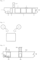
- FIGS. 1 to 4 are schematic side views of a floating structure with a dual fuel propulsion system according to various exemplary embodiments.
- a floating structure having a dual fuel propulsion system includes a plurality of fuel tanks 3 and 4 for storing fuel in a hull 1 and a propulsion system 5 generating propulsion power by fuel fed from the fuel tanks 3 and 4.
- the dual fuel propulsion system may be configured to include the above-mentioned plurality of fuel tanks 3 and 4 and propulsion system 5 and a pipe capable of feeding fuel received in each of the fuel tanks 3 and 4 to the propulsion system 5.
- the floating structure used herein implies a offshore plant such as an oil FPSO used while floating anywhere at sea at normal times, in addition to various ships such as a bulk carrier, a container ship, a passenger ship, or the like.
- the floating structure when it is a bulk carrier, a liquid cargo carrier, etc., it may include at least one storage tank 7 capable of storing freights in addition to the fuel tanks 3 and 4.
- the storage tanks 7 may also receive freights usable as fuel. In this case, it is to be noted that it is different from fuel stored in the fuel tank in the specification since it is handled as freights, not fuel.
- a liquefied fuel such as heavy oil (HFO) or diesel oil (MDO), etc.
- fuel for the propulsion system
- a liquefied fuel such as heavy oil (HFO) or diesel oil (MDO), etc.
- HFO heavy oil
- MDO diesel oil
- any one of the gaseous fuels such as LPG, LNG, DME, CNG, or the like, may be stored in the remaining fuel tank (i.e., a fuel tank 4 for fuel gas).
- the liquid fuel and gaseous fuel used herein are determined according to whether fuel fed to the propulsion system, that is, the engine is liquid or gas. That is, fuel such as heavy oil, diesel oil, etc., maintaining a liquid state when being fed to the propulsion system is referred to as a liquid fuel and fuel such as LNG, LPG, DME, CNG, or the like, fed as a gas state when being fed to the propulsion system even though a liquid state or a gas state is present when being stored in the fuel tank is referred to as gas fuel.
- a liquid fuel and fuel such as LNG, LPG, DME, CNG, or the like
- fuel gas containing hydrocarbon component such as LNG, LPG, CNG, or the like.
- LNG i.e., liquefied natural gas is generated by liquefying natural gas collected from a gas field, wherein the main component of the liquefied natural gas is methane.
- LNG is advantageous in respects to space efficiency by reducing its volume to approximately 1/600 when being liquefied by lowering the temperature or applying pressure, but should be charged in a specifically insulated tank or container to keep temperature at a boiling point or less during transportation and storage, since it has a low boiling point of approximately -162°C.
- LPG i.e., liquefied petroleum gas is generated by cooling and liquefying heavy hydrocarbon (two or more carbon atoms) component generated at the time of collecting crude oil from an oil field or purifying crude oil or heavy hydrocarbon component collected together at the time of collecting natural gas at a relatively low pressure (6 - 7 kg/cm 2 ).
- LNG is advantageous in terms of storage and transportation since the volume thereof is reduced to approximately 1/250 at the time of liquefying, wherein the main component thereof is propane and butane and may include a small amount of ethane, propylene, butylene, or the like.
- CNG i.e., compressed natural gas is generated by compressing natural gas at approximately 20 MPa to use the natural gas as fuel.
- DME i.e., dimethyl ether is a kind of ether and has lower flammability than the LPG and low toxicity and has a small environmental effect since a small amount of exhaust fume is generated during combustion due to high oxygen concentration.
- Each of the fuel tanks 3 and 4 includes an appropriate insulation system and sealing system according to a type of fuel to be received.
- an example of the fuel tank receiving liquefying gas such as LNG, LPG, or the like, may include a membrane type tank or an independent type tank that has been used in the liquefying gas storage tank field.
- FIG. 1 shows that both the fuel tank 3 for liquid fuel and the fuel gas tank 4 (for example, LNG, LPG, DME, CNG, or the like) are mounted in the hull 1 of the floating structure
- the fuel tank 3 for liquefied fuel may be modified to be mounted in the hull 1 of the floating structure and the fuel gas tank 4 may be modified to be mounted on the deck of the floating structure.
- the fuel gas tank 4 may be modified to be mounted in the hull 1 of the floating structure and the fuel tank 3 for liquid fuel may be modified to be mounted on the deck of the floating structure.
- an example of the propulsion system 5 may include a low pressure gas injection engine such as, for example, dual fuel diesel electric (DFDE), a high pressure gas injection engine such as, for example, ME-GI (Gas Injection Engine available from Man B&W Co.), and a gas turbine, or the like. If the propulsion system uses at least two types of fuels as fuel, any propulsion system may be used.
- DFDE dual fuel diesel electric
- ME-GI Gas Injection Engine available from Man B&W Co.
- the meanings "capable of using at least two types of fuels” include a concept of using a mixture of at least two types of fuels while using at least two types of fuels and a concept of selectively using at least one of two or more fuels, if necessary, while using at least two types of fuels.
- FIG. 3 shows a diagram for explaining a method for additionally mounting the fuel gas tank 4 such as, another kind, for example, LNG, etc., in the floating structure designed and built to have one type, for example, only the fuel tank 3 for liquid fuel.
- the fuel gas tank 4 such as, another kind, for example, LNG, etc.
- the hull of the floating structure is separated into two portions, that is, a bow portion 1a and a stern portion 1b by being divided at any position.
- An additional hull portion 1c having the fuel tank 4 embedded therein is inserted between the bow portion 1a and the stern portion 1b and is integrated into one hull by welding.
- a method for additionally mounting the fuel tank in the hull as shown in FIG. 3 as well as a method for additionally mounting the fuel tank on the deck on the floating structure as shown in FIG. 2 may be used.
- these fuel tanks 3 and 4 may be configured to permanently attach to the hull 1 and may be configured to be removed, if necessary, as shown in FIG. 4 .
- the fuel tank capable of storing fuel may be selectively mounted in consideration of the usage of fuel.
- factors for determining the usage of fuel there may be a kind of propulsion system, the price of fuel, season, and environmental factor, or the like.
- the fuel tank 3 for liquefied fuel such as heavy oil and the fuel gas tank 4 such as LNG, etc. are each installed in the hull of the floating structure and the removable fuel tank 9 as the fuel tank for liquid fuel is additionally mounted in the hull of the floating structure if it is expected that the usage of liquid fuel among these fuels will be increased and the removable fuel tank 9 as the fuel gas tank may be additionally mounted if it is expected that the usage of the gas fuel will be increased.
- the removable fuel tank 9 is removed and the empty space in the hull formed thereby may be used as a space for loading freight.
- the removable fuel tank 9 is removed when the only the liquid fuel having relatively higher density is used and the space in the hull formed thereby is used as a cargo space, etc., and then, when the gaseous fuel is mainly used, the fuel gas tank as the removable fuel tank 9 may be used by being mounted therein.
- it may be configured to store different kinds of fuel in one space, for example, one fuel tank 3 or 4, if necessary, as shown in FIG. 5 .
- LNG or LPG may be selectively stored in the same space, if necessary, and heavy oil or diesel oil may be selectively stored in the same space, if necessary.
- different kinds of fuel tanks may be selectively received in one space as shown in FIG. 4 and different kinds of fuel may be selectively received in the same space as shown in FIG. 5 .
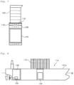
- FIG. 6 is a side view for schematically showing the floating structure, i.e., the container ship when the fuel gas tank is mounted under the accommodation space and FIG. 7 is a magnified view of main parts of FIG. 6 .
- FIG. 8 is a side view for schematically showing the floating structure, i.e., the container ship when the fuel gas tank is mounted under the cargo space and
- FIG. 9 is a magnified view of the main parts of FIG. 8 .
- a plurality of containers are loaded in the hull and on a upper deck 101a other than an accommodation space 102 in which crewmen reside, an engine room 106 in which the propulsion system 105 is mounted, a space in which the LNG fuel tank 104 is mounted, a machinery space 108, or the like.
- the size of the container ship is large, it is preferable to move from the stern of the accommodation space 102 to the central portion of the hull to secure the field of view.
- the lower space of the accommodation space 102 which is difficult to load containers is used as a space in which the LNG fuel tank 104 is disposed, in order to efficiently use the space.
- the central part of the hull implies a portion in front of the bow of the hull in which the propulsion system 105 is mounted and does not necessarily imply the central portion of the length direction of the hull.
- the inventors propose a method for using liquefied gas such as LNG (or LPG, DME), etc., as fuel of the propulsion system for propelling a cargo ship such as a container ship, in order to meet the price increase of liquid fuel, such as heavy oil or diesel oil, etc., while avoiding the increasingly reinforced environmental regulations.
- the dual fuel propulsion system such as the high pressure gas injection engine such as ME-GI and the low pressure gas injection engine such as DFDE capable of using the dual fuel as fuel, etc., is used.
- FIGS. 6 and 7 - which do not fall under the scope of the claims-show that the ME-GI is used as the propulsion system 105 and the LNG fuel tank104 as the fuel gas tank is mounted under the accommodation space 102 and FIGS. 8 and 9 show that the ME-GI is used as the propulsion system 105 and the LNG fuel tank 104 as the fuel gas tank is installed under the cargo space 114.
- the heavy oil fuel tank as the fuel tank for liquid fuel for storing heavy oil to be used as fuel together with LNG in the propulsion system 105 may be mounted under the accommodation space 102, together with the LNG fuel tank 104 and may also be mounted in the hull.
- One of the LNG fuel tank and the heavy oil fuel tank may be removed from the hull and may be replaced with other kinds of fuel tank.
- the number of LNG fuel tanks and the number of heavy oil fuel tanks mounted in the hull may be controlled according to the usage of fuel.
- the membrane type tank or the independent type tank may be used as the LNG fuel tank 104, in particular, an IMO type B tank may be used. That is, in order for the LNG fuel tank 104 to be removed from the inside of the hull, it is preferable to use the independent type tank.
- the IMO type B tank where the hull protecting member is mounted below the tank (between the tank and the floor inside the hull) as a secondary barrier is preferably used.
- Various apparatuses for feeding fuel to the dual fuel propulsion system (gas injection engine) as the propulsion system 105 are preferably disposed in the machinery space 108 disposed over the LNG fuel tank 104.
- the fuel supply system for supplying LNG to the engine as fuel there are the re-condenser, the high pressure pump, the cooler, the high pressure vaporizer, the boil off gas compressor, or the like.
- the proper insulation is required for the fuel supply system, such that it is preferable that the LNG fuel tank 104 as the fuel tank and the machinery space 108 is maximally close to each other.
- the increased distance between the LNG fuel tank 104 and the machinery space 108 is not preferable, since heat loss is increased in view of the insulation aspect for the transferring pipe for transferring LNG.
- the machinery space 108 is disposed between the LNG fuel tank 104 and the accommodation space 102.
- this space since it is difficult to load freights 115 such as container, etc., under the accommodation space 102, it is preferable to use this space as a space where the LNG fuel tank 104 will be disposed.
- the machinery space 108 is close to the LNG fuel tank 104, it is preferable to dispose the machinery space 108 over the LNG fuel tank 104 while being disposed under the accommodation space 102.
- a fuel feeding pipe may be mounted under the hull or at the side thereof.
- the LNG fuel tank 104 and the machinery space 108 are classified as a gas dangerous space and the accommodation space 102 disposed on the upper deck 101a is classified as a gas safe space. Therefore, when fire or the leakage of fuel, i.e., LNG occurs in the LNG fuel tank 104 or the machinery space 108 that is a gas dangerous space, there is a need to secure the safety of crewmen, passengers, or freight by blocking the gas safe space from the gas dangerous space.
- a coffer dam 116 is formed over the machinery space 108 and the deck between the coffer dam 116 and the accommodation space 102 is formed of bulkhead capable of blocking heat and gas, such as, for example, an A-60 bulkhead 118, etc., when fire occurs.
- the coffer dam 116 and the bulkhead 118 may serve as a blocking member for safety.
- FIGS. 7 and 9 shows the A-60 bulkhead 118 as a bulkhead capable of blocking heat and gas, but the present invention is not limited thereto. Any bulkhead may be used if it can block heat and gas when fire occurs.
- the bottom of the LNG fuel tank 104 i.e., the floor of the hull is formed of a duplication floor.
- the coffer dam 116 implies a structure where an empty space between a pair of bulk heads, that is, a void space is formed.
- the A-60 bulkhead 118 implies a bulkhead (formed by single gas tight bulkhead of all-welled construction) securing insulation and gas cutoff for 60 minutes when fire occurs.
- the coffer dam 116 and the A-60 bulkhead 118 may be used to partition between the cargo space 114 and the LNG fuel tank 104 as shown in FIGS. 8 and 9 .
- FIG. 9 shows that the machinery space 108 is omitted and the coffer dam 116 is disposed over the LNG fuel tank 104, the machinery space 108 may be disposed between the LNG fuel tank 104 an the coffer dam 116 as shown in FIG. 7 .
- At least two types of fuels tanks 104 may be disposed in parallel according to a width direction of the hull and the length of the LNG fuel tank 104 may have a dimension approximately corresponding to a container of a length of 40ft as shown in FIG. 9 .
- the removable LNG fuel tank 104 may be mounted from the hull and may store the gaseous fuel such as LPG, CNG, DME, etc., in addition to LNG.
- the fuel tank for liquid fuel storing liquid fuel such as heavy oil or diesel oil, etc., is mounted in parallel with the LNG fuel tank 104 in left or right or front and back directions and may be installed in a separate place in the hull.
- the present invention may mount the fuel tank for at least three different fuels.
- the present invention may be used for propulsion by selectively employing the most efficient fuel at the present time.
- the present invention may configure a multi fuel propulsion system using the system.
- the fuel from the fuel tank is fed to the propulsion system configured of the gas injection engine such as the ME-GI engine or the DFDE engine, or the like, is described, the fuel may be fed to the gas turbine, etc., in addition to the above-mentioned engines for power generation.
- the gas injection engine such as the ME-GI engine or the DFDE engine, or the like
Landscapes
- Chemical & Material Sciences (AREA)
- Engineering & Computer Science (AREA)
- Combustion & Propulsion (AREA)
- Mechanical Engineering (AREA)
- Ocean & Marine Engineering (AREA)
- Filling Or Discharging Of Gas Storage Vessels (AREA)
- Cooling, Air Intake And Gas Exhaust, And Fuel Tank Arrangements In Propulsion Units (AREA)
Description
- The present invention relates to a floating structure with a fuel gas tank, and more particularly, to a floating structure with a fuel gas tank for storing a gaseous fuel fed to a dual fuel propulsion system disposed under a cargo space.
- Generally, various ships such as a bulk carrier, a container ship, a passenger ship, or the like, have employed a fuel supply system using heavy oil (HFO or MDO) such as a bunker C oil, that is a liquid fuel, as propulsion fuel.
- In the existing fuel supply system, if heavy oil, or the like, used as fuel combust, it causes serious environmental pollution due to harmful substances included in exhaust gas. Since a demand for preventing environmental pollution is increasingly regulated throughout the whole world, regulations for a propulsion system using heavy oil as fuel oil have also been reinforced. As a result, costs have been continuously increased in order to meet these regulations.
- In addition, when oil prices increase due to factors such as depletion of fossil fuel, localized insecurity, or the like, several operational problems such as the rapid increase of fuel expenses of a ship using heavy oil as fuel, etc., are caused.
- Therefore, research into a fuel supply system, etc., using clean fuel such as LNG (or, LPG, CNG, DME, etc.), that is a liquefied or gaseous fuel without using heavy oil (or, MDO) or instead of using a minimum amount of heavy oil, as fuel oil of various ships, mainly using LNG (or, LPG, CNG, DME, etc.) as fuel when heavy oil (or MDO) is expensive or standards required for environmental protection are increased, and mainly using heavy oil (or, MDO) when heavy oil (or MDO) is cheap or environmental standards are weak has been continuously conducted.
-
GB 1 496 978 AJP 2006 300319 A - The present has been made in an effort to provide a floating structure with a fuel gas tank having advantages of efficiently using a space by disposing a fuel gas tank for storing a gaseous fuel fed to a dual fuel propulsion system disposed under a cargo space.
- According to the present invention, the floating structure with the fuel gas tank for storing a gaseous fuel supplied to the dual fuel propulsion system disposed under the cargo space is provided.
- As a result, according to the floating structure according to the present invention, it is possible to efficiently use the space in the hull and over the upper deck.
-
-
FIG. 1 is a side cross-sectional view schematically showing a floating structure with a dual fuel propulsion system according to an exemplary embodiment of the present invention; -
FIG. 2 is a side cross-sectional view schematically showing a floating structure with a dual fuel propulsion system according to another exemplary embodiment of the present invention; -
FIG. 3 is a diagram for explaining a method for additionally mounting another type of fuel tank in a floating structure designed and built to have only one type of fuel tank; -
FIG. 4 is a side cross-sectional view schematically showing a floating structure with a dual fuel propulsion system according to another exemplary embodiment of the present invention; -
FIG. 5 is a diagram for explaining a concept selectively receiving different types of fuel in the same space according to the present invention; -
FIG. 6 is a side view schematically showing a floating structure when a fuel gas tank is disposed under an accommodation space and is not part of the present invention; -
FIG. 7 is a magnified view of a major part ofFIG. 6 ; -
FIG. 8 is a side view schematically showing a floating structure when a fuel gas tank is disposed under a cargo space; and -
FIG. 9 is a magnified view of major parts ofFIG. 8 . -
1: hull 1a: bow portion 1b: stern portion 1c: additional hull portion 1d: opening 3: fuel tank for liquid fuel 4: fuel gas tank 5: propulsion system 7: storage tank 9: removable fuel tank 101a: upper deck 102: accommodation space 104: fuel tank 105: propulsion system 106: engine room 108: machinery space 114: cargo space 115: freight 116: coffer dam 118: A-60 bulkhead - According to an aspect of the present invention, there is provided a floating structure as defined in
claim 1. - The blocking member may be a coffer dam formed to have a void space between a pair of bulk heads.
- The blocking member may be a bulkhead capable of blocking heat and gas generated during a fire.
- The bulkhead capable of blocking heat and gas generated during a fire may be disposed between the coffer dam and the cargo space.
- The fuel stored in the fuel gas tank may be a liquefied gas and the machinery space may include at least one of a re-condenser, a pump, a cooler, a vaporizer, and a boil off gas compressor for treating the liquefied gas to be used in a propulsion system or a power generation apparatus.
- The floating structure may further include a propulsion system using a gaseous fuel stored in the fuel gas tank as fuel.
- The propulsion system may be a high pressure gas injection engine or a low pressure gas injection engine capable of generating power using dual fuel. In addition, the propulsion system may be a gas turbine.
- The fuel gas tank may be removed from the hull. The floating structure may further include the fuel tank for liquid fuel stored to use at least one of heavy oil and diesel oil as fuel.
- The fuel gas tank may be an independent tank capable of storing a liquefied gas.
- Hereinafter, a floating structure having a dual fuel propulsion system according to an exemplary embodiment of the present invention will be described in detail with reference to the accompanying drawings.
-
FIGS. 1 to 4 are schematic side views of a floating structure with a dual fuel propulsion system according to various exemplary embodiments. - As shown in
FIG. 1 , a floating structure having a dual fuel propulsion system includes a plurality offuel tanks hull 1 and apropulsion system 5 generating propulsion power by fuel fed from thefuel tanks - The dual fuel propulsion system may be configured to include the above-mentioned plurality of
fuel tanks propulsion system 5 and a pipe capable of feeding fuel received in each of thefuel tanks propulsion system 5. - The floating structure used herein implies a offshore plant such as an oil FPSO used while floating anywhere at sea at normal times, in addition to various ships such as a bulk carrier, a container ship, a passenger ship, or the like.
- As shown in
FIG. 1 , when the floating structure is a bulk carrier, a liquid cargo carrier, etc., it may include at least onestorage tank 7 capable of storing freights in addition to thefuel tanks storage tanks 7 may also receive freights usable as fuel. In this case, it is to be noted that it is different from fuel stored in the fuel tank in the specification since it is handled as freights, not fuel. - According to the exemplary embodiment, a liquefied fuel such as heavy oil (HFO) or diesel oil (MDO), etc., generally widely used as fuel for the propulsion system may be stored in a part of the
fuel tanks 3 and 4 (i.e., afuel tank 3 for liquid fuel) and any one of the gaseous fuels such as LPG, LNG, DME, CNG, or the like, may be stored in the remaining fuel tank (i.e., afuel tank 4 for fuel gas). - The liquid fuel and gaseous fuel used herein are determined according to whether fuel fed to the propulsion system, that is, the engine is liquid or gas. That is, fuel such as heavy oil, diesel oil, etc., maintaining a liquid state when being fed to the propulsion system is referred to as a liquid fuel and fuel such as LNG, LPG, DME, CNG, or the like, fed as a gas state when being fed to the propulsion system even though a liquid state or a gas state is present when being stored in the fuel tank is referred to as gas fuel.
- Generally, as fuel other than heavy oil, it is preferable to use fuel gas containing hydrocarbon component, such as LNG, LPG, CNG, or the like.
- LNG, i.e., liquefied natural gas is generated by liquefying natural gas collected from a gas field, wherein the main component of the liquefied natural gas is methane. LNG is advantageous in respects to space efficiency by reducing its volume to approximately 1/600 when being liquefied by lowering the temperature or applying pressure, but should be charged in a specifically insulated tank or container to keep temperature at a boiling point or less during transportation and storage, since it has a low boiling point of approximately -162°C.
- LPG, i.e., liquefied petroleum gas is generated by cooling and liquefying heavy hydrocarbon (two or more carbon atoms) component generated at the time of collecting crude oil from an oil field or purifying crude oil or heavy hydrocarbon component collected together at the time of collecting natural gas at a relatively low pressure (6 - 7 kg/cm2). LNG is advantageous in terms of storage and transportation since the volume thereof is reduced to approximately 1/250 at the time of liquefying, wherein the main component thereof is propane and butane and may include a small amount of ethane, propylene, butylene, or the like.
- CNG, i.e., compressed natural gas is generated by compressing natural gas at approximately 20 MPa to use the natural gas as fuel.
- DME, i.e., dimethyl ether is a kind of ether and has lower flammability than the LPG and low toxicity and has a small environmental effect since a small amount of exhaust fume is generated during combustion due to high oxygen concentration.
- Each of the
fuel tanks - Although
FIG. 1 shows that both thefuel tank 3 for liquid fuel and the fuel gas tank 4 (for example, LNG, LPG, DME, CNG, or the like) are mounted in thehull 1 of the floating structure, thefuel tank 3 for liquefied fuel may be modified to be mounted in thehull 1 of the floating structure and thefuel gas tank 4 may be modified to be mounted on the deck of the floating structure. In addition, thefuel gas tank 4 may be modified to be mounted in thehull 1 of the floating structure and thefuel tank 3 for liquid fuel may be modified to be mounted on the deck of the floating structure. - Meanwhile, an example of the
propulsion system 5 may include a low pressure gas injection engine such as, for example, dual fuel diesel electric (DFDE), a high pressure gas injection engine such as, for example, ME-GI (Gas Injection Engine available from Man B&W Co.), and a gas turbine, or the like. If the propulsion system uses at least two types of fuels as fuel, any propulsion system may be used. - In the specification, the meanings "capable of using at least two types of fuels" include a concept of using a mixture of at least two types of fuels while using at least two types of fuels and a concept of selectively using at least one of two or more fuels, if necessary, while using at least two types of fuels.
-
FIG. 3 shows a diagram for explaining a method for additionally mounting thefuel gas tank 4 such as, another kind, for example, LNG, etc., in the floating structure designed and built to have one type, for example, only thefuel tank 3 for liquid fuel. - According to the method shown in
FIG. 3 , the hull of the floating structure is separated into two portions, that is, abow portion 1a and astern portion 1b by being divided at any position. An additional hull portion 1c having thefuel tank 4 embedded therein is inserted between thebow portion 1a and thestern portion 1b and is integrated into one hull by welding. - According to the present invention, a method for additionally mounting the fuel tank in the hull as shown in
FIG. 3 as well as a method for additionally mounting the fuel tank on the deck on the floating structure as shown inFIG. 2 may be used. - When the plurality of
fuel tanks hull 1 as shown inFIG. 1 or when thefuel tank 4 capable of storing another kind of fuel is added to thehull 1 as shown inFIG. 3 , thesefuel tanks hull 1 and may be configured to be removed, if necessary, as shown inFIG. 4 . - As shown in
FIG. 4 , when theremovable fuel tank 9 is provided, the fuel tank capable of storing fuel, that is larger amount used, may be selectively mounted in consideration of the usage of fuel. As factors for determining the usage of fuel, there may be a kind of propulsion system, the price of fuel, season, and environmental factor, or the like. - For example, the
fuel tank 3 for liquefied fuel such as heavy oil and thefuel gas tank 4 such as LNG, etc., are each installed in the hull of the floating structure and theremovable fuel tank 9 as the fuel tank for liquid fuel is additionally mounted in the hull of the floating structure if it is expected that the usage of liquid fuel among these fuels will be increased and theremovable fuel tank 9 as the fuel gas tank may be additionally mounted if it is expected that the usage of the gas fuel will be increased. - In addition, when the amount of fuel is small, the
removable fuel tank 9 is removed and the empty space in the hull formed thereby may be used as a space for loading freight. - For example, since the gaseous fuel such as LNG, or the like, has density lower than the liquid fuel such as HFO, etc., the
removable fuel tank 9 is removed when the only the liquid fuel having relatively higher density is used and the space in the hull formed thereby is used as a cargo space, etc., and then, when the gaseous fuel is mainly used, the fuel gas tank as theremovable fuel tank 9 may be used by being mounted therein. - In addition, according to the present invention, it may be configured to store different kinds of fuel in one space, for example, one
fuel tank FIG. 5 . For example, LNG or LPG may be selectively stored in the same space, if necessary, and heavy oil or diesel oil may be selectively stored in the same space, if necessary. - As such, according to the present invention, different kinds of fuel tanks may be selectively received in one space as shown in
FIG. 4 and different kinds of fuel may be selectively received in the same space as shown inFIG. 5 . - Hereinafter, an example of when the dual fuel propulsion system is mounted as the propulsion system and the present invention is applied to a container ship having the fuel gas tank for storing gaseous fuel to be fed to the dual fuel propulsion system will be described with reference to
FIGS. 8 and9 . -
FIG. 6 is a side view for schematically showing the floating structure, i.e., the container ship when the fuel gas tank is mounted under the accommodation space andFIG. 7 is a magnified view of main parts ofFIG. 6 .FIG. 8 is a side view for schematically showing the floating structure, i.e., the container ship when the fuel gas tank is mounted under the cargo space andFIG. 9 is a magnified view of the main parts ofFIG. 8 . - In the container ship, a plurality of containers are loaded in the hull and on a
upper deck 101a other than anaccommodation space 102 in which crewmen reside, anengine room 106 in which thepropulsion system 105 is mounted, a space in which theLNG fuel tank 104 is mounted, amachinery space 108, or the like. When the size of the container ship is large, it is preferable to move from the stern of theaccommodation space 102 to the central portion of the hull to secure the field of view. As a result, the lower space of theaccommodation space 102 which is difficult to load containers is used as a space in which theLNG fuel tank 104 is disposed, in order to efficiently use the space. In the specification, the central part of the hull implies a portion in front of the bow of the hull in which thepropulsion system 105 is mounted and does not necessarily imply the central portion of the length direction of the hull. - The inventors propose a method for using liquefied gas such as LNG (or LPG, DME), etc., as fuel of the propulsion system for propelling a cargo ship such as a container ship, in order to meet the price increase of liquid fuel, such as heavy oil or diesel oil, etc., while avoiding the increasingly reinforced environmental regulations. To this end, the dual fuel propulsion system, such as the high pressure gas injection engine such as ME-GI and the low pressure gas injection engine such as DFDE capable of using the dual fuel as fuel, etc., is used.
-
FIGS. 6 and7 - which do not fall under the scope of the claims-show that the ME-GI is used as thepropulsion system 105 and the LNG fuel tank104 as the fuel gas tank is mounted under theaccommodation space 102 andFIGS. 8 and9 show that the ME-GI is used as thepropulsion system 105 and theLNG fuel tank 104 as the fuel gas tank is installed under thecargo space 114. The heavy oil fuel tank as the fuel tank for liquid fuel for storing heavy oil to be used as fuel together with LNG in thepropulsion system 105 may be mounted under theaccommodation space 102, together with theLNG fuel tank 104 and may also be mounted in the hull. - One of the LNG fuel tank and the heavy oil fuel tank may be removed from the hull and may be replaced with other kinds of fuel tank. In addition, according to the present invention, the number of LNG fuel tanks and the number of heavy oil fuel tanks mounted in the hull may be controlled according to the usage of fuel.
- The membrane type tank or the independent type tank may be used as the
LNG fuel tank 104, in particular, an IMO type B tank may be used. That is, in order for theLNG fuel tank 104 to be removed from the inside of the hull, it is preferable to use the independent type tank. Among various kinds of independent tanks, the IMO type B tank where the hull protecting member is mounted below the tank (between the tank and the floor inside the hull) as a secondary barrier is preferably used. - Various apparatuses for feeding fuel to the dual fuel propulsion system (gas injection engine) as the
propulsion system 105 are preferably disposed in themachinery space 108 disposed over theLNG fuel tank 104. As the fuel supply system for supplying LNG to the engine as fuel, there are the re-condenser, the high pressure pump, the cooler, the high pressure vaporizer, the boil off gas compressor, or the like. - When the liquefied gas in the extremely low temperature state is used as fuel, the proper insulation is required for the fuel supply system, such that it is preferable that the
LNG fuel tank 104 as the fuel tank and themachinery space 108 is maximally close to each other. The increased distance between theLNG fuel tank 104 and themachinery space 108 is not preferable, since heat loss is increased in view of the insulation aspect for the transferring pipe for transferring LNG. - In addition, as shown in
FIG. 7 , when theLNG fuel tank 104 is disposed under theaccommodation space 102, it is preferable that themachinery space 108 is disposed between theLNG fuel tank 104 and theaccommodation space 102. As described above, since it is difficult to loadfreights 115 such as container, etc., under theaccommodation space 102, it is preferable to use this space as a space where theLNG fuel tank 104 will be disposed. Further, since it is preferable that themachinery space 108 is close to theLNG fuel tank 104, it is preferable to dispose themachinery space 108 over theLNG fuel tank 104 while being disposed under theaccommodation space 102. - Further, it is preferable in terms of maintenance to dispose the
machinery space 108 between theaccommodation space 102 and theLNG fuel tank 104. - In order to feed the LNG as fuel stored in the LNG fuel tank to the ME-GI engine as the
propulsion system 105, the LNG is fed to thepropulsion system 105 through themachinery space 108. In this case, in order to feed the LNG as fuel from themachinery space 108 to thepropulsion system 105, a fuel feeding pipe may be mounted under the hull or at the side thereof. - The
LNG fuel tank 104 and themachinery space 108 are classified as a gas dangerous space and theaccommodation space 102 disposed on theupper deck 101a is classified as a gas safe space. Therefore, when fire or the leakage of fuel, i.e., LNG occurs in theLNG fuel tank 104 or themachinery space 108 that is a gas dangerous space, there is a need to secure the safety of crewmen, passengers, or freight by blocking the gas safe space from the gas dangerous space. - To this end, a
coffer dam 116 is formed over themachinery space 108 and the deck between thecoffer dam 116 and theaccommodation space 102 is formed of bulkhead capable of blocking heat and gas, such as, for example, anA-60 bulkhead 118, etc., when fire occurs. Thecoffer dam 116 and thebulkhead 118 may serve as a blocking member for safety. -
FIGS. 7 and9 shows theA-60 bulkhead 118 as a bulkhead capable of blocking heat and gas, but the present invention is not limited thereto. Any bulkhead may be used if it can block heat and gas when fire occurs. - Meanwhile, the bottom of the
LNG fuel tank 104, i.e., the floor of the hull is formed of a duplication floor. - The
coffer dam 116 implies a structure where an empty space between a pair of bulk heads, that is, a void space is formed. In addition, theA-60 bulkhead 118 implies a bulkhead (formed by single gas tight bulkhead of all-welled construction) securing insulation and gas cutoff for 60 minutes when fire occurs. - The
coffer dam 116 and theA-60 bulkhead 118 may be used to partition between thecargo space 114 and theLNG fuel tank 104 as shown inFIGS. 8 and9 . AlthoughFIG. 9 shows that themachinery space 108 is omitted and thecoffer dam 116 is disposed over theLNG fuel tank 104, themachinery space 108 may be disposed between theLNG fuel tank 104 an thecoffer dam 116 as shown inFIG. 7 . - At least two types of
fuels tanks 104 may be disposed in parallel according to a width direction of the hull and the length of theLNG fuel tank 104 may have a dimension approximately corresponding to a container of a length of 40ft as shown inFIG. 9 . - According to the present invention, the removable
LNG fuel tank 104 may be mounted from the hull and may store the gaseous fuel such as LPG, CNG, DME, etc., in addition to LNG. In addition, the fuel tank for liquid fuel storing liquid fuel such as heavy oil or diesel oil, etc., is mounted in parallel with theLNG fuel tank 104 in left or right or front and back directions and may be installed in a separate place in the hull. - Although the example where the fuel tank for two different fuels is mounted in the floating structure is described above, the present invention may mount the fuel tank for at least three different fuels.
- Although the price and efficiency for each fuel may be changed according to times and several factors, the present invention may be used for propulsion by selectively employing the most efficient fuel at the present time. In addition, when the development of an electric propulsion system or a solar power generation or a wind power generation system having excellent efficiency is completed in a short period of time, the present invention may configure a multi fuel propulsion system using the system.
- In addition, although the example where the fuel from the fuel tank is fed to the propulsion system configured of the gas injection engine such as the ME-GI engine or the DFDE engine, or the like, is described, the fuel may be fed to the gas turbine, etc., in addition to the above-mentioned engines for power generation.
- As described above, although the floating structure with the fuel gas tank according to the present invention is described with reference to the accompanying drawings, the present invention is not limited to the above exemplary embodiments and drawings and thus, may be variously modified and changed within the scope of the appended claims.
Claims (11)
- A floating structure with a fuel gas tank storing a gaseous fuel used as fuel while floating at sea, the floating structure being a container ship voyaged under its own power by a propulsion system (105), comprising:the fuel gas tank (104) disposed in a hull of the floating structure;a cargo space (114) disposed on top of the fuel gas tank (104) on an upper deck (101a) of the floating structure;a blocking member disposed between the cargo space (114) and the fuel gas tank (104) to secure the safety of freight (115) loaded in the cargo space (114); anda machinery space (108) for treating fuel stored in the fuel gas tank (104) is disposed over the fuel gas tank (104) and the blocking member is disposed between the machinery space and the cargo space (114).
- The floating structure with a fuel gas tank of claim 1, wherein the blocking member is a coffer dam (116) configured by forming a void space between a pair of bulkheads.
- The floating structure with a fuel gas tank of claim 1, wherein the blocking member is a bulkhead (118) blocking heat and gas generated during fire.
- The floating structure with a fuel gas tank of claim 2, wherein the bulkhead (118) blocking heat and gas generated during fire is disposed between the coffer dam (116) and the cargo space (114).
- The floating structure with a fuel gas tank of claim 1, wherein the fuel stored in the fuel gas tank (104) is a liquefied gas, and
the machinery space (108) is provided with at least one of a re-condenser, a pump, a cooler, a vaporizer, and a boil off gas compressor to use the liquefied gas in the propulsion system (105) or a power generation apparatus. - The floating structure with a fuel gas tank of claim 1, wherein the propulsion system (105) is configured to use the gaseous fuel stored in the fuel gas tank (104) as fuel.
- The floating structure with a fuel gas tank of claim 6, wherein the propulsion system (105) is a high pressure gas injection engine or a low pressure gas injection engine generating power by using dual fuel.
- The floating structure with a fuel gas tank of claim 6, wherein the propulsion system (105) is a gas turbine.
- The floating structure with a fuel gas tank of claim 1, wherein the fuel gas tank (104) is removable from the hull.
- The floating structure with a fuel gas tank of claim 7, further comprising a fuel tank for liquid fuel storing at least one of heavy oil and diesel oil as fuel.
- The floating structure with a fuel gas tank of claim 1, wherein the fuel gas tank is an independent type tank storing liquefied gas.
Priority Applications (1)
| Application Number | Priority Date | Filing Date | Title |
|---|---|---|---|
| EP21180560.1A EP3919363A1 (en) | 2009-10-16 | 2010-10-05 | A container ship using fuel gas as propulsion fuel |
Applications Claiming Priority (2)
| Application Number | Priority Date | Filing Date | Title |
|---|---|---|---|
| KR1020090098985A KR100961867B1 (en) | 2009-10-16 | 2009-10-16 | Floating structure with a fuel gas tank |
| PCT/KR2010/006787 WO2011046314A2 (en) | 2009-10-16 | 2010-10-05 | Floating structure with fuel tank for gas fuel |
Related Child Applications (2)
| Application Number | Title | Priority Date | Filing Date |
|---|---|---|---|
| EP21180560.1A Division-Into EP3919363A1 (en) | 2009-10-16 | 2010-10-05 | A container ship using fuel gas as propulsion fuel |
| EP21180560.1A Division EP3919363A1 (en) | 2009-10-16 | 2010-10-05 | A container ship using fuel gas as propulsion fuel |
Publications (4)
| Publication Number | Publication Date |
|---|---|
| EP2489586A2 EP2489586A2 (en) | 2012-08-22 |
| EP2489586A4 EP2489586A4 (en) | 2017-06-21 |
| EP2489586B1 true EP2489586B1 (en) | 2023-10-04 |
| EP2489586C0 EP2489586C0 (en) | 2023-10-04 |
Family
ID=42369686
Family Applications (2)
| Application Number | Title | Priority Date | Filing Date |
|---|---|---|---|
| EP10765924.5A Active EP2489586B1 (en) | 2009-10-16 | 2010-10-05 | Floating structure with fuel tank for gas fuel |
| EP21180560.1A Withdrawn EP3919363A1 (en) | 2009-10-16 | 2010-10-05 | A container ship using fuel gas as propulsion fuel |
Family Applications After (1)
| Application Number | Title | Priority Date | Filing Date |
|---|---|---|---|
| EP21180560.1A Withdrawn EP3919363A1 (en) | 2009-10-16 | 2010-10-05 | A container ship using fuel gas as propulsion fuel |
Country Status (7)
| Country | Link |
|---|---|
| US (1) | US8834218B2 (en) |
| EP (2) | EP2489586B1 (en) |
| JP (1) | JP5577408B2 (en) |
| KR (1) | KR100961867B1 (en) |
| CN (1) | CN102666269B (en) |
| AU (1) | AU2010307573B2 (en) |
| WO (1) | WO2011046314A2 (en) |
Families Citing this family (17)
| Publication number | Priority date | Publication date | Assignee | Title |
|---|---|---|---|---|
| KR100961867B1 (en) * | 2009-10-16 | 2010-06-09 | 대우조선해양 주식회사 | Floating structure with a fuel gas tank |
| KR101210916B1 (en) * | 2009-10-16 | 2012-12-11 | 대우조선해양 주식회사 | Floating structure with a fuel gas tank |
| JP6143407B2 (en) * | 2010-12-07 | 2017-06-07 | 三菱重工業株式会社 | Ship |
| CN103625607B (en) * | 2012-08-20 | 2017-11-03 | 中集船舶海洋工程设计研究院有限公司 | container ship |
| SG11201501548WA (en) * | 2014-01-07 | 2015-08-28 | Daewoo Shipbuilding & Marine | Fuel gas supply system and method of ship |
| KR101599401B1 (en) * | 2014-07-18 | 2016-03-14 | 대우조선해양 주식회사 | Operation Method of Engine for a Ship |
| KR101606701B1 (en) * | 2014-08-18 | 2016-03-28 | 대우조선해양 주식회사 | Container Ship And Arrangement Method Of The Same |
| KR101747538B1 (en) * | 2015-04-07 | 2017-06-14 | 현대중공업 주식회사 | Gas Fuelled Container Carrier |
| JP6002813B1 (en) | 2015-05-29 | 2016-10-05 | 株式会社大島造船所 | Ship |
| FI126423B (en) * | 2015-10-07 | 2016-11-30 | Rolls-Royce Marine As | Marine surface craft |
| KR20180095724A (en) * | 2016-01-12 | 2018-08-27 | 엑셀러레이트 리쿼팩션 솔루션즈, 엘엘씨 | Liquefied natural gas ship |
| KR102114525B1 (en) * | 2016-12-28 | 2020-05-22 | 현대중공업 주식회사 | Gas Fuelled Container Carrier |
| KR102196987B1 (en) * | 2016-12-29 | 2020-12-30 | 현대중공업 주식회사 | Gas Fuelled Container Carrier |
| JP7193250B2 (en) * | 2018-04-24 | 2022-12-20 | 佐々木造船株式会社 | vessel |
| CN110920803B (en) * | 2019-11-21 | 2020-12-22 | 中集船舶海洋工程设计研究院有限公司 | Container ship and loading and unloading device thereof |
| CN112572172A (en) * | 2020-12-04 | 2021-03-30 | 沪东中华造船(集团)有限公司 | Large container ship with hydrogen fuel cell electrically propelled |
| GR1010144B (en) * | 2021-03-11 | 2021-12-30 | Δημητριος Ηρακλη Κωσταλας | Cargo ship |
Citations (9)
| Publication number | Priority date | Publication date | Assignee | Title |
|---|---|---|---|---|
| GB1000298A (en) | 1960-08-17 | 1965-08-04 | Exxon Research Engineering Co | Thermally insulated tanks and marine vessels comprising the same |
| US3326167A (en) | 1965-08-02 | 1967-06-20 | Exxon Research Engineering Co | Tanker |
| DE4302821C1 (en) | 1993-01-27 | 1994-07-21 | Kvaerner Warnow Werft Gmbh | Container ship with increased load space |
| WO1999028182A1 (en) | 1997-12-03 | 1999-06-10 | Ima International Maritime Advisers | A transport ship |
| WO2005032927A1 (en) | 2003-09-04 | 2005-04-14 | Aker Mtw Werft Gmbh | Container ship |
| US20060225448A1 (en) | 2004-10-25 | 2006-10-12 | Damien Feger | Energy system making use of a thermoelectric power unit and natural gas stored in liquid form |
| WO2007147931A1 (en) | 2006-06-19 | 2007-12-27 | Wärtsilä Finland Oy | A marine vessel |
| WO2008075882A1 (en) | 2006-12-18 | 2008-06-26 | Samsung Heavy Ind. Co., Ltd. | Fuel supply apparatus of liquefied gas carrier and fuel supply method thereof |
| WO2009011497A2 (en) | 2007-07-19 | 2009-01-22 | Daewoo Shipbuilding & Marine Engineering Co., Ltd. | Fuel gas supply system and method of ship |
Family Cites Families (26)
| Publication number | Priority date | Publication date | Assignee | Title |
|---|---|---|---|---|
| FR1388133A (en) | 1963-01-09 | 1965-02-05 | Phs Van Ommeren N V | Tank vessel |
| JPS529282A (en) * | 1975-07-07 | 1977-01-24 | Uingu Tatsuku Suchiimushitsupu | Carrying vessel of general cargo and liquid cargo |
| US4135465A (en) * | 1977-01-11 | 1979-01-23 | Dudley Fred T | Tank for fuel tanker |
| JPH06156365A (en) * | 1992-11-17 | 1994-06-03 | Ishikawajima Harima Heavy Ind Co Ltd | Fuel oil tank for vessel |
| GB9501169D0 (en) * | 1995-01-20 | 1995-03-08 | British Petroleum Co Plc | Improvements in and relating to ships |
| US5839383A (en) * | 1995-10-30 | 1998-11-24 | Enron Lng Development Corp. | Ship based gas transport system |
| US6135044A (en) * | 1998-01-29 | 2000-10-24 | Ima International Maritime Advisers | Transport ship |
| US6076480A (en) * | 1999-02-11 | 2000-06-20 | The United States Of America As Represented By The Secretary Of The Navy | Fuel storing water ballast tank internally structured for reducing retention of water and overboard discharge of fuel |
| US6237347B1 (en) * | 1999-03-31 | 2001-05-29 | Exxonmobil Upstream Research Company | Method for loading pressurized liquefied natural gas into containers |
| US6899046B2 (en) * | 2002-11-26 | 2005-05-31 | Exxonmobil Chemical Patents Inc. | Shipping methanol for a methanol to olefin unit in non-methanol carriers |
| US7240499B1 (en) * | 2003-07-10 | 2007-07-10 | Atp Oil & Gas Corporation | Method for transporting compressed natural gas to prevent explosions |
| FI118680B (en) * | 2003-12-18 | 2008-02-15 | Waertsilae Finland Oy | A gas supply arrangement in a craft and a method for controlling gas pressure in a craft gas supply arrangement |
| US6966272B2 (en) * | 2004-03-03 | 2005-11-22 | Great American Lines, Inc. | Multi-mode ship for transporting vehicles |
| FR2876981B1 (en) | 2004-10-27 | 2006-12-15 | Gaz Transp Et Technigaz Soc Pa | DEVICE FOR SUPPLYING FUEL TO AN ENERGY PRODUCTION PLANT IN A SHIP |
| JP2008519221A (en) * | 2004-11-08 | 2008-06-05 | シエル・インターナシヨネイル・リサーチ・マーチヤツピイ・ベー・ウイ | Liquefied natural gas floating storage regasifier |
| JP4116995B2 (en) * | 2005-03-08 | 2008-07-09 | 株式会社新来島どっく | Fuel tank on the upper deck |
| KR100667500B1 (en) | 2005-04-15 | 2007-01-10 | 한국가스공사 | Lng storage tank and modules for constructing it |
| FI122137B (en) | 2006-06-27 | 2011-09-15 | Waertsilae Finland Oy | Gas fueled ship fuel system |
| JP4753834B2 (en) * | 2006-10-23 | 2011-08-24 | 中国電力株式会社 | Ship and NGH supply method to ship |
| US20080190352A1 (en) * | 2007-02-12 | 2008-08-14 | Daewoo Shipbuilding & Marine Engineering Co., Ltd. | Lng tank ship and operation thereof |
| EP2003389A3 (en) * | 2007-06-15 | 2017-04-19 | Daewoo Shipbuilding & Marine Engineering Co., Ltd | Method and apparatus for treating boil-off gas in an LNG carrier having a reliquefaction plant, and LNG carrier having said apparatus for treating boil-off gas |
| KR20090010614A (en) | 2007-07-24 | 2009-01-30 | 현대중공업 주식회사 | Improved the bilge handling system for cargo tank insulation space of liquefied lng gas carriers |
| KR20090005497U (en) * | 2007-12-03 | 2009-06-08 | 대우조선해양 주식회사 | Container ship batch structure using ship body |
| EP2072885A1 (en) | 2007-12-21 | 2009-06-24 | Cryostar SAS | Natural gas supply method and apparatus. |
| KR20090098387A (en) * | 2008-03-14 | 2009-09-17 | 대우조선해양 주식회사 | The ship had a driving clean fuel storage tank on an upper deck |
| KR100961867B1 (en) * | 2009-10-16 | 2010-06-09 | 대우조선해양 주식회사 | Floating structure with a fuel gas tank |
-
2009
- 2009-10-16 KR KR1020090098985A patent/KR100961867B1/en active IP Right Grant
-
2010
- 2010-10-05 WO PCT/KR2010/006787 patent/WO2011046314A2/en active Application Filing
- 2010-10-05 JP JP2012534097A patent/JP5577408B2/en active Active
- 2010-10-05 EP EP10765924.5A patent/EP2489586B1/en active Active
- 2010-10-05 CN CN201080056727.1A patent/CN102666269B/en not_active Ceased
- 2010-10-05 US US13/502,354 patent/US8834218B2/en active Active
- 2010-10-05 AU AU2010307573A patent/AU2010307573B2/en not_active Ceased
- 2010-10-05 EP EP21180560.1A patent/EP3919363A1/en not_active Withdrawn
Patent Citations (10)
| Publication number | Priority date | Publication date | Assignee | Title |
|---|---|---|---|---|
| GB1000298A (en) | 1960-08-17 | 1965-08-04 | Exxon Research Engineering Co | Thermally insulated tanks and marine vessels comprising the same |
| US3326167A (en) | 1965-08-02 | 1967-06-20 | Exxon Research Engineering Co | Tanker |
| DE4302821C1 (en) | 1993-01-27 | 1994-07-21 | Kvaerner Warnow Werft Gmbh | Container ship with increased load space |
| WO1999028182A1 (en) | 1997-12-03 | 1999-06-10 | Ima International Maritime Advisers | A transport ship |
| WO2005032927A1 (en) | 2003-09-04 | 2005-04-14 | Aker Mtw Werft Gmbh | Container ship |
| CN1845845A (en) | 2003-09-04 | 2006-10-11 | 埃克Mtw造船厂有限公司 | Container ship |
| US20060225448A1 (en) | 2004-10-25 | 2006-10-12 | Damien Feger | Energy system making use of a thermoelectric power unit and natural gas stored in liquid form |
| WO2007147931A1 (en) | 2006-06-19 | 2007-12-27 | Wärtsilä Finland Oy | A marine vessel |
| WO2008075882A1 (en) | 2006-12-18 | 2008-06-26 | Samsung Heavy Ind. Co., Ltd. | Fuel supply apparatus of liquefied gas carrier and fuel supply method thereof |
| WO2009011497A2 (en) | 2007-07-19 | 2009-01-22 | Daewoo Shipbuilding & Marine Engineering Co., Ltd. | Fuel gas supply system and method of ship |
Non-Patent Citations (13)
| Title |
|---|
| ANONYMOUS: "LNG-fuelled cargo ship design contract", MER, 1 November 2008 (2008-11-01), pages 37, XP093197445 |
| ANONYMOUS: "LNG-fuelled fjord ferries", HANSA INTERNATIONAL MARITIME JOURNAL, vol. 144, no. 6, 1 June 2007 (2007-06-01), DE , pages 34, 36, XP093197453, ISSN: 0017-7504 |
| ANONYMOUS: "The Machinery Page", MARTIN'S MARINE ENGINEERING, 1 December 2023 (2023-12-01), XP093195921, Retrieved from the Internet <URL:https://www.dieselduck.info/machine/> |
| DNV: "Chapter 13 - GAS FUELLED ENGINE INSTALLATIONS", RULES FOR CLASSIFICATION OF SHIPS, NEW BUILDINGS, PART 6, 1 January 2007 (2007-01-01), pages 1 - 22, XP093197450 |
| DNV: "PART 6 CHAPTER 13 GAS FUELLED ENGINE INSTALLATIONS", DET NORSKE VERITAS - RULES FOR CLASSIFICATION OF SHIPS NEWBUILDINGS SPECIAL EQUIPMENT AND SYSTEMS ADDITIONAL CLASS, 1 January 2007 (2007-01-01), XP093195946 |
| HANSEN JAN FREDRIK: "COMPARISON OF ELECTRIC POWER AND PROPULSION PLANTS FOR LNG CARRIERS WITH DIFFERENT PROPULSION SYSTEMS", MARTIN'S MARINE ENGINEERING - PRIME MOVERS, 1 January 2007 (2007-01-01), pages 1 - 15, XP093195919, Retrieved from the Internet <URL:https://www.dieselduck.info/machine/02%20propulsion/2007%20Comparison%20LNG%20carrier%20propulsion.pdf> |
| IMCO: "Recommendation concerning fire safety requirements for cargo ships", IMCO RESOLUTION A.327(IX), 17 December 1975 (1975-12-17), XP093195950 |
| IMO: "International Code for the Construction and Equipment of Ships Carrying Liquefied Gases in Bulk IGC Code", ICG CODE. ELECTRONIC EDITION, LONDON, 1 January 1993 (1993-01-01), London, XP093195947 |
| LEVANDER OSKAR: "Turning the page in ship propulsion, by switching to LNG", PRESENTATION WÄRTSILÄ, COPENHAGEN, 3 March 2008 (2008-03-03), Copenhagen, XP093195911, Retrieved from the Internet <URL:https://www.dieselduck.info/library/05%20environmental/2008%20Wartsila%20propulsion%20alternatives.pdf> |
| MARITIME SAFETY COMMITTEE,: "Interim guidelines on safety for natural gas-fueled engine installations in ships", RESOLUTION MSC.285(86), ADOPTED ON 01/06/2009 BY THE MSC AND PUBLISHED THE SAME DAY, 1 June 2009 (2009-06-01), XP093195924 |
| MARITIME SAFETY COMMITTEE: "INTERIM GUIDELINES ON SAFETY FOR NATURAL GAS-FUELLED ENGINE INSTALLATIONS IN SHIPS", RESOLUTION MSC.5(48) : ADOPTION OF THE INTERNATIONAL CODE FOR THE CONSTRUCTION AND EQUIPMENT OF SHIPS CARRYING LIQUEFIED GASES IN BULK IN ITS LATEST VERSION, ADOPTED AND PUBLISHED BY THE IMO ON 17/06/1983 ("1983 IGC CODE")., 1 June 2009 (2009-06-01), XP093195913 |
| OSBERG TORILL GRIMSTAD: "Gas engine propulsion in ships", DNV - DET INORSKE VERITAS, WASHINTON, 1 June 2008 (2008-06-01), Washinton, pages 1 - 31, XP093195953 |
| PENG YAN, ZHU YU-SONG: "Study on selection of propulsion system for LNG carrier", WORLD SHIPPING, vol. 31, no. 2, 1 April 2008 (2008-04-01), pages 36 - 37, XP093197456, DOI: 10.16176/j.cnki.21.1284.2008.02.013 |
Also Published As
| Publication number | Publication date |
|---|---|
| WO2011046314A2 (en) | 2011-04-21 |
| AU2010307573B2 (en) | 2014-10-02 |
| US8834218B2 (en) | 2014-09-16 |
| CN102666269B (en) | 2016-01-20 |
| EP2489586A2 (en) | 2012-08-22 |
| EP2489586A4 (en) | 2017-06-21 |
| CN102666269A (en) | 2012-09-12 |
| US20120244762A1 (en) | 2012-09-27 |
| EP3919363A1 (en) | 2021-12-08 |
| JP5577408B2 (en) | 2014-08-20 |
| JP2013508203A (en) | 2013-03-07 |
| EP2489586C0 (en) | 2023-10-04 |
| KR100961867B1 (en) | 2010-06-09 |
| WO2011046314A3 (en) | 2011-09-01 |
| AU2010307573A1 (en) | 2012-06-07 |
Similar Documents
| Publication | Publication Date | Title |
|---|---|---|
| EP2489586B1 (en) | Floating structure with fuel tank for gas fuel | |
| EP2374710B1 (en) | Floating structure with fuel tank for gas fuel | |
| KR100961868B1 (en) | Container ship with a fuel gas tank | |
| US9067663B2 (en) | Floating structure having an upper deck fuel tank | |
| KR101560475B1 (en) | Container carrier's optimized gas fuel tank arrangement using open bulkhead | |
| KR20140058477A (en) | Floating structure with a propulsion system using heterogeneous fuel | |
| KR101577794B1 (en) | Floating structure with a propulsion system using heterogeneous fuel | |
| KR101681729B1 (en) | Container ship | |
| KR20110041940A (en) | Floating structure with a propulsion system using heterogeneous fuel | |
| KR101628809B1 (en) | Floating structure having an attachable fuel gas tank | |
| KR100978066B1 (en) | Floating structure with a pipe system using heterogeneous fuel | |
| KR20140058479A (en) | Floating structure with a propulsion system using heterogeneous fuel | |
| KR20110027441A (en) | Floating structure with a propulsion system using heterogeneous fuel | |
| KR101599308B1 (en) | Floating structure with a fuel gas tank | |
| KR20110047684A (en) | Floating structure having a movable fuel tank | |
| KR20160023761A (en) | Floating structure with a propulsion system using heterogeneous fuel | |
| KR20140058478A (en) | Floating structure with a propulsion system using heterogeneous fuel |
Legal Events
| Date | Code | Title | Description |
|---|---|---|---|
| PUAI | Public reference made under article 153(3) epc to a published international application that has entered the european phase |
Free format text: ORIGINAL CODE: 0009012 |
|
| 17P | Request for examination filed |
Effective date: 20101022 |
|
| AK | Designated contracting states |
Kind code of ref document: A2 Designated state(s): AL AT BE BG CH CY CZ DE DK EE ES FI FR GB GR HR HU IE IS IT LI LT LU LV MC MK MT NL NO PL PT RO RS SE SI SK SM TR |
|
| R17D | Deferred search report published (corrected) |
Effective date: 20110901 |
|
| DAX | Request for extension of the european patent (deleted) | ||
| A4 | Supplementary search report drawn up and despatched |
Effective date: 20170524 |
|
| RIC1 | Information provided on ipc code assigned before grant |
Ipc: B63B 25/12 20060101ALI20170518BHEP Ipc: B63B 43/00 20060101ALI20170518BHEP Ipc: B63B 11/04 20060101ALI20170518BHEP Ipc: B63B 25/16 20060101AFI20170518BHEP Ipc: B63H 21/38 20060101ALI20170518BHEP Ipc: B63H 21/14 20060101ALI20170518BHEP Ipc: B63H 21/12 20060101ALI20170518BHEP |
|
| STAA | Information on the status of an ep patent application or granted ep patent |
Free format text: STATUS: EXAMINATION IS IN PROGRESS |
|
| 17Q | First examination report despatched |
Effective date: 20180921 |
|
| STAA | Information on the status of an ep patent application or granted ep patent |
Free format text: STATUS: EXAMINATION IS IN PROGRESS |
|
| STAA | Information on the status of an ep patent application or granted ep patent |
Free format text: STATUS: EXAMINATION IS IN PROGRESS |
|
| TPAC | Observations filed by third parties |
Free format text: ORIGINAL CODE: EPIDOSNTIPA |
|
| REG | Reference to a national code |
Ref country code: DE Ref legal event code: R079 Ref document number: 602010069067 Country of ref document: DE Free format text: PREVIOUS MAIN CLASS: B63B0025160000 Ipc: B63H0021200000 Ref country code: DE Ref legal event code: R079 Free format text: PREVIOUS MAIN CLASS: B63B0025160000 Ipc: B63H0021200000 |
|
| GRAP | Despatch of communication of intention to grant a patent |
Free format text: ORIGINAL CODE: EPIDOSNIGR1 |
|
| STAA | Information on the status of an ep patent application or granted ep patent |
Free format text: STATUS: GRANT OF PATENT IS INTENDED |
|
| RIC1 | Information provided on ipc code assigned before grant |
Ipc: B63B 11/04 20060101ALI20230313BHEP Ipc: B63H 21/12 20060101ALI20230313BHEP Ipc: B63H 21/38 20060101ALI20230313BHEP Ipc: B63B 25/12 20060101ALI20230313BHEP Ipc: B63H 21/14 20060101ALI20230313BHEP Ipc: B63B 43/00 20060101ALI20230313BHEP Ipc: B63B 25/16 20060101ALI20230313BHEP Ipc: B63H 21/20 20060101AFI20230313BHEP |
|
| INTG | Intention to grant announced |
Effective date: 20230414 |
|
| GRAS | Grant fee paid |
Free format text: ORIGINAL CODE: EPIDOSNIGR3 |
|
| GRAA | (expected) grant |
Free format text: ORIGINAL CODE: 0009210 |
|
| STAA | Information on the status of an ep patent application or granted ep patent |
Free format text: STATUS: THE PATENT HAS BEEN GRANTED |
|
| RAP3 | Party data changed (applicant data changed or rights of an application transferred) |
Owner name: HANWHA OCEAN CO., LTD. |
|
| AK | Designated contracting states |
Kind code of ref document: B1 Designated state(s): AL AT BE BG CH CY CZ DE DK EE ES FI FR GB GR HR HU IE IS IT LI LT LU LV MC MK MT NL NO PL PT RO RS SE SI SK SM TR |
|
| P01 | Opt-out of the competence of the unified patent court (upc) registered |
Effective date: 20230824 |
|
| REG | Reference to a national code |
Ref country code: GB Ref legal event code: FG4D |
|
| REG | Reference to a national code |
Ref country code: CH Ref legal event code: EP |
|
| REG | Reference to a national code |
Ref country code: IE Ref legal event code: FG4D |
|
| REG | Reference to a national code |
Ref country code: DE Ref legal event code: R096 Ref document number: 602010069067 Country of ref document: DE |
|
| P04 | Withdrawal of opt-out of the competence of the unified patent court (upc) registered |
Effective date: 20231106 |
|
| U01 | Request for unitary effect filed |
Effective date: 20231103 |
|
| U07 | Unitary effect registered |
Designated state(s): AT BE BG DE DK EE FI FR IT LT LU LV MT NL PT SE SI Effective date: 20231109 |
|
| U20 | Renewal fee paid [unitary effect] |
Year of fee payment: 14 Effective date: 20231106 |
|
| REG | Reference to a national code |
Ref country code: NO Ref legal event code: T2 Effective date: 20231004 |
|
| PGFP | Annual fee paid to national office [announced via postgrant information from national office to epo] |
Ref country code: NO Payment date: 20231020 Year of fee payment: 14 |
|
| PG25 | Lapsed in a contracting state [announced via postgrant information from national office to epo] |
Ref country code: GR Free format text: LAPSE BECAUSE OF FAILURE TO SUBMIT A TRANSLATION OF THE DESCRIPTION OR TO PAY THE FEE WITHIN THE PRESCRIBED TIME-LIMIT Effective date: 20240105 |
|
| PG25 | Lapsed in a contracting state [announced via postgrant information from national office to epo] |
Ref country code: IS Free format text: LAPSE BECAUSE OF FAILURE TO SUBMIT A TRANSLATION OF THE DESCRIPTION OR TO PAY THE FEE WITHIN THE PRESCRIBED TIME-LIMIT Effective date: 20240204 |
|
| PG25 | Lapsed in a contracting state [announced via postgrant information from national office to epo] |
Ref country code: ES Free format text: LAPSE BECAUSE OF FAILURE TO SUBMIT A TRANSLATION OF THE DESCRIPTION OR TO PAY THE FEE WITHIN THE PRESCRIBED TIME-LIMIT Effective date: 20231004 |
|
| PG25 | Lapsed in a contracting state [announced via postgrant information from national office to epo] |
Ref country code: IS Free format text: LAPSE BECAUSE OF FAILURE TO SUBMIT A TRANSLATION OF THE DESCRIPTION OR TO PAY THE FEE WITHIN THE PRESCRIBED TIME-LIMIT Effective date: 20240204 Ref country code: GR Free format text: LAPSE BECAUSE OF FAILURE TO SUBMIT A TRANSLATION OF THE DESCRIPTION OR TO PAY THE FEE WITHIN THE PRESCRIBED TIME-LIMIT Effective date: 20240105 Ref country code: ES Free format text: LAPSE BECAUSE OF FAILURE TO SUBMIT A TRANSLATION OF THE DESCRIPTION OR TO PAY THE FEE WITHIN THE PRESCRIBED TIME-LIMIT Effective date: 20231004 |
|
| PG25 | Lapsed in a contracting state [announced via postgrant information from national office to epo] |
Ref country code: RS Free format text: LAPSE BECAUSE OF FAILURE TO SUBMIT A TRANSLATION OF THE DESCRIPTION OR TO PAY THE FEE WITHIN THE PRESCRIBED TIME-LIMIT Effective date: 20231004 Ref country code: PL Free format text: LAPSE BECAUSE OF FAILURE TO SUBMIT A TRANSLATION OF THE DESCRIPTION OR TO PAY THE FEE WITHIN THE PRESCRIBED TIME-LIMIT Effective date: 20231004 Ref country code: HR Free format text: LAPSE BECAUSE OF FAILURE TO SUBMIT A TRANSLATION OF THE DESCRIPTION OR TO PAY THE FEE WITHIN THE PRESCRIBED TIME-LIMIT Effective date: 20231004 |
|
| REG | Reference to a national code |
Ref country code: CH Ref legal event code: PL |
|
| PLBI | Opposition filed |
Free format text: ORIGINAL CODE: 0009260 |
|
| PG25 | Lapsed in a contracting state [announced via postgrant information from national office to epo] |
Ref country code: CH Free format text: LAPSE BECAUSE OF NON-PAYMENT OF DUE FEES Effective date: 20231031 |
|
| PG25 | Lapsed in a contracting state [announced via postgrant information from national office to epo] |
Ref country code: CZ Free format text: LAPSE BECAUSE OF FAILURE TO SUBMIT A TRANSLATION OF THE DESCRIPTION OR TO PAY THE FEE WITHIN THE PRESCRIBED TIME-LIMIT Effective date: 20231004 |
|
| PG25 | Lapsed in a contracting state [announced via postgrant information from national office to epo] |
Ref country code: SK Free format text: LAPSE BECAUSE OF FAILURE TO SUBMIT A TRANSLATION OF THE DESCRIPTION OR TO PAY THE FEE WITHIN THE PRESCRIBED TIME-LIMIT Effective date: 20231004 |
|
| PG25 | Lapsed in a contracting state [announced via postgrant information from national office to epo] |
Ref country code: SM Free format text: LAPSE BECAUSE OF FAILURE TO SUBMIT A TRANSLATION OF THE DESCRIPTION OR TO PAY THE FEE WITHIN THE PRESCRIBED TIME-LIMIT Effective date: 20231004 Ref country code: SK Free format text: LAPSE BECAUSE OF FAILURE TO SUBMIT A TRANSLATION OF THE DESCRIPTION OR TO PAY THE FEE WITHIN THE PRESCRIBED TIME-LIMIT Effective date: 20231004 Ref country code: RO Free format text: LAPSE BECAUSE OF FAILURE TO SUBMIT A TRANSLATION OF THE DESCRIPTION OR TO PAY THE FEE WITHIN THE PRESCRIBED TIME-LIMIT Effective date: 20231004 Ref country code: CZ Free format text: LAPSE BECAUSE OF FAILURE TO SUBMIT A TRANSLATION OF THE DESCRIPTION OR TO PAY THE FEE WITHIN THE PRESCRIBED TIME-LIMIT Effective date: 20231004 Ref country code: CH Free format text: LAPSE BECAUSE OF NON-PAYMENT OF DUE FEES Effective date: 20231031 |
|
| PLBI | Opposition filed |
Free format text: ORIGINAL CODE: 0009260 |
|
| 26 | Opposition filed |
Opponent name: EASTERN PACIFIC SHIPPING PTE. LTD. Effective date: 20240701 |
|
| PG25 | Lapsed in a contracting state [announced via postgrant information from national office to epo] |
Ref country code: MC Free format text: LAPSE BECAUSE OF FAILURE TO SUBMIT A TRANSLATION OF THE DESCRIPTION OR TO PAY THE FEE WITHIN THE PRESCRIBED TIME-LIMIT Effective date: 20231004 |
|
| PG25 | Lapsed in a contracting state [announced via postgrant information from national office to epo] |
Ref country code: MC Free format text: LAPSE BECAUSE OF FAILURE TO SUBMIT A TRANSLATION OF THE DESCRIPTION OR TO PAY THE FEE WITHIN THE PRESCRIBED TIME-LIMIT Effective date: 20231004 |
|
| 26 | Opposition filed |
Opponent name: STRAWMAN LIMITED Effective date: 20240703 Opponent name: HD HYUNDAI HEAVY INDUSTRIES CO., LTD. Effective date: 20240702 |
|
| PLAB | Opposition data, opponent's data or that of the opponent's representative modified |
Free format text: ORIGINAL CODE: 0009299OPPO |