EP3224496B1 - Disc brake, in particular for commercial vehicles - Google Patents
Disc brake, in particular for commercial vehicles Download PDFInfo
- Publication number
- EP3224496B1 EP3224496B1 EP15790842.7A EP15790842A EP3224496B1 EP 3224496 B1 EP3224496 B1 EP 3224496B1 EP 15790842 A EP15790842 A EP 15790842A EP 3224496 B1 EP3224496 B1 EP 3224496B1
- Authority
- EP
- European Patent Office
- Prior art keywords
- brake
- adjusting
- disk
- rotation
- adjustment
- Prior art date
- Legal status (The legal status is an assumption and is not a legal conclusion. Google has not performed a legal analysis and makes no representation as to the accuracy of the status listed.)
- Active
Links
- 230000008878 coupling Effects 0.000 claims description 13
- 238000010168 coupling process Methods 0.000 claims description 13
- 238000005859 coupling reaction Methods 0.000 claims description 13
- 230000007246 mechanism Effects 0.000 claims description 13
- 230000001419 dependent effect Effects 0.000 claims description 10
- 230000033001 locomotion Effects 0.000 description 21
- 238000000034 method Methods 0.000 description 7
- 230000008569 process Effects 0.000 description 7
- 239000000463 material Substances 0.000 description 6
- 230000006835 compression Effects 0.000 description 5
- 238000007906 compression Methods 0.000 description 5
- 238000009434 installation Methods 0.000 description 5
- 230000008859 change Effects 0.000 description 4
- 230000002441 reversible effect Effects 0.000 description 4
- 238000006073 displacement reaction Methods 0.000 description 3
- 230000008901 benefit Effects 0.000 description 2
- 239000002184 metal Substances 0.000 description 2
- 230000036961 partial effect Effects 0.000 description 2
- 230000002829 reductive effect Effects 0.000 description 2
- 230000003213 activating effect Effects 0.000 description 1
- 230000004913 activation Effects 0.000 description 1
- 239000000853 adhesive Substances 0.000 description 1
- 230000001070 adhesive effect Effects 0.000 description 1
- 230000002411 adverse Effects 0.000 description 1
- 230000000712 assembly Effects 0.000 description 1
- 238000000429 assembly Methods 0.000 description 1
- 230000005540 biological transmission Effects 0.000 description 1
- 230000015572 biosynthetic process Effects 0.000 description 1
- 230000000903 blocking effect Effects 0.000 description 1
- 239000011248 coating agent Substances 0.000 description 1
- 238000000576 coating method Methods 0.000 description 1
- 230000001427 coherent effect Effects 0.000 description 1
- 150000001875 compounds Chemical class 0.000 description 1
- 230000008602 contraction Effects 0.000 description 1
- 230000005489 elastic deformation Effects 0.000 description 1
- 238000004146 energy storage Methods 0.000 description 1
- 230000007613 environmental effect Effects 0.000 description 1
- 238000005755 formation reaction Methods 0.000 description 1
- 230000006872 improvement Effects 0.000 description 1
- 238000003780 insertion Methods 0.000 description 1
- 230000037431 insertion Effects 0.000 description 1
- 238000009830 intercalation Methods 0.000 description 1
- 239000002346 layers by function Substances 0.000 description 1
- 230000000149 penetrating effect Effects 0.000 description 1
- 230000002040 relaxant effect Effects 0.000 description 1
- 230000000717 retained effect Effects 0.000 description 1
- 230000001360 synchronised effect Effects 0.000 description 1
- 238000011144 upstream manufacturing Methods 0.000 description 1
Images


Classifications
-
- F—MECHANICAL ENGINEERING; LIGHTING; HEATING; WEAPONS; BLASTING
- F16—ENGINEERING ELEMENTS AND UNITS; GENERAL MEASURES FOR PRODUCING AND MAINTAINING EFFECTIVE FUNCTIONING OF MACHINES OR INSTALLATIONS; THERMAL INSULATION IN GENERAL
- F16D—COUPLINGS FOR TRANSMITTING ROTATION; CLUTCHES; BRAKES
- F16D65/00—Parts or details
- F16D65/38—Slack adjusters
- F16D65/40—Slack adjusters mechanical
- F16D65/52—Slack adjusters mechanical self-acting in one direction for adjusting excessive play
- F16D65/56—Slack adjusters mechanical self-acting in one direction for adjusting excessive play with screw-thread and nut
- F16D65/567—Slack adjusters mechanical self-acting in one direction for adjusting excessive play with screw-thread and nut for mounting on a disc brake
-
- F—MECHANICAL ENGINEERING; LIGHTING; HEATING; WEAPONS; BLASTING
- F16—ENGINEERING ELEMENTS AND UNITS; GENERAL MEASURES FOR PRODUCING AND MAINTAINING EFFECTIVE FUNCTIONING OF MACHINES OR INSTALLATIONS; THERMAL INSULATION IN GENERAL
- F16D—COUPLINGS FOR TRANSMITTING ROTATION; CLUTCHES; BRAKES
- F16D55/00—Brakes with substantially-radial braking surfaces pressed together in axial direction, e.g. disc brakes
- F16D55/02—Brakes with substantially-radial braking surfaces pressed together in axial direction, e.g. disc brakes with axially-movable discs or pads pressed against axially-located rotating members
- F16D55/22—Brakes with substantially-radial braking surfaces pressed together in axial direction, e.g. disc brakes with axially-movable discs or pads pressed against axially-located rotating members by clamping an axially-located rotating disc between movable braking members, e.g. movable brake discs or brake pads
- F16D55/224—Brakes with substantially-radial braking surfaces pressed together in axial direction, e.g. disc brakes with axially-movable discs or pads pressed against axially-located rotating members by clamping an axially-located rotating disc between movable braking members, e.g. movable brake discs or brake pads with a common actuating member for the braking members
- F16D55/225—Brakes with substantially-radial braking surfaces pressed together in axial direction, e.g. disc brakes with axially-movable discs or pads pressed against axially-located rotating members by clamping an axially-located rotating disc between movable braking members, e.g. movable brake discs or brake pads with a common actuating member for the braking members the braking members being brake pads
- F16D55/226—Brakes with substantially-radial braking surfaces pressed together in axial direction, e.g. disc brakes with axially-movable discs or pads pressed against axially-located rotating members by clamping an axially-located rotating disc between movable braking members, e.g. movable brake discs or brake pads with a common actuating member for the braking members the braking members being brake pads in which the common actuating member is moved axially, e.g. floating caliper disc brakes
-
- F—MECHANICAL ENGINEERING; LIGHTING; HEATING; WEAPONS; BLASTING
- F16—ENGINEERING ELEMENTS AND UNITS; GENERAL MEASURES FOR PRODUCING AND MAINTAINING EFFECTIVE FUNCTIONING OF MACHINES OR INSTALLATIONS; THERMAL INSULATION IN GENERAL
- F16D—COUPLINGS FOR TRANSMITTING ROTATION; CLUTCHES; BRAKES
- F16D65/00—Parts or details
- F16D65/14—Actuating mechanisms for brakes; Means for initiating operation at a predetermined position
- F16D65/16—Actuating mechanisms for brakes; Means for initiating operation at a predetermined position arranged in or on the brake
- F16D65/18—Actuating mechanisms for brakes; Means for initiating operation at a predetermined position arranged in or on the brake adapted for drawing members together, e.g. for disc brakes
-
- F—MECHANICAL ENGINEERING; LIGHTING; HEATING; WEAPONS; BLASTING
- F16—ENGINEERING ELEMENTS AND UNITS; GENERAL MEASURES FOR PRODUCING AND MAINTAINING EFFECTIVE FUNCTIONING OF MACHINES OR INSTALLATIONS; THERMAL INSULATION IN GENERAL
- F16D—COUPLINGS FOR TRANSMITTING ROTATION; CLUTCHES; BRAKES
- F16D2121/00—Type of actuator operation force
- F16D2121/14—Mechanical
-
- F—MECHANICAL ENGINEERING; LIGHTING; HEATING; WEAPONS; BLASTING
- F16—ENGINEERING ELEMENTS AND UNITS; GENERAL MEASURES FOR PRODUCING AND MAINTAINING EFFECTIVE FUNCTIONING OF MACHINES OR INSTALLATIONS; THERMAL INSULATION IN GENERAL
- F16D—COUPLINGS FOR TRANSMITTING ROTATION; CLUTCHES; BRAKES
- F16D2125/00—Components of actuators
- F16D2125/18—Mechanical mechanisms
- F16D2125/20—Mechanical mechanisms converting rotation to linear movement or vice versa
- F16D2125/22—Mechanical mechanisms converting rotation to linear movement or vice versa acting transversely to the axis of rotation
- F16D2125/28—Cams; Levers with cams
- F16D2125/32—Cams; Levers with cams acting on one cam follower
-
- F—MECHANICAL ENGINEERING; LIGHTING; HEATING; WEAPONS; BLASTING
- F16—ENGINEERING ELEMENTS AND UNITS; GENERAL MEASURES FOR PRODUCING AND MAINTAINING EFFECTIVE FUNCTIONING OF MACHINES OR INSTALLATIONS; THERMAL INSULATION IN GENERAL
- F16D—COUPLINGS FOR TRANSMITTING ROTATION; CLUTCHES; BRAKES
- F16D2125/00—Components of actuators
- F16D2125/18—Mechanical mechanisms
- F16D2125/20—Mechanical mechanisms converting rotation to linear movement or vice versa
- F16D2125/34—Mechanical mechanisms converting rotation to linear movement or vice versa acting in the direction of the axis of rotation
- F16D2125/40—Screw-and-nut
Definitions
- the invention relates to a disc brake, in particular for commercial vehicles, with a brake disc, a brake caliper, at least one lying on one side of the brake disc within the brake caliper application device, an axially displaceable device, the brake pad by means of at least one adjusting spindle axially in the direction of the brake when the brake is actuated Disc rotates, wherein the adjusting spindle is rotatable, has an external thread and is screwed into a threaded bore in the displaceable device, and with a Nachstellgetriebe which is rotatable about an axis parallel to the axis of rotation of the brake disc axis and upon rotation in a readjusting effecting first direction of rotation because of an acting in this direction of rotation rotary coupling the adjusting screw twisted.
- Such disc brakes are usually actuated pneumatically or electromechanically.
- wear adjusting devices are known in different versions, for example, mechanical adjustments, as they provide today in common commercial vehicle disc brakes for a constant within certain limits clearance. Since the adjustments must maintain a constant clearance under all driving and braking situations, the demands on the precision of such adjustments are very high. It determines in particular the clearance, which must be overcome to the pad system, the pivoting example, a serving for tensioning rotary lever and thus the maximum applied braking force and the brake power reserve.
- the adjusting device is activated during braking and a comparison with a setpoint clearance, for example, by a feed element of an application device of the disc brake. So if wear of brake pads and / or the brake disc with a resulting change (increase) of the clearance, so there is an automatic readjustment of the pads by means of the adjusting device, for example by an adjustment of pressure punches.
- a structurally predetermined clearance is depicted in the form of fixed geometric variables in the components involved in the adjustment process.
- Disc brakes which have a lever-operated brake application device.
- Zuspann-device itself belongs in these cases, a rotary lever with an eccentrically acting brake shaft whose rotational or sliding axis is parallel to the brake disc plane and which acts on a displaceable in the caliper pressure piece.
- pressure piece is sometimes also from a Traverse or a bridge the speech.
- only a "displaceable element” will be discussed below.
- the displaceable element itself is non-rotatably arranged in the brake caliper.
- a center Spindle device mounted, which has a rotatable and provided with a pressure collar adjusting nut and a screwed therein, but rotatably held pressure spindle or adjusting spindle. About these parts, the clamping force is transmitted to at least one brake pad, which is then pressed against the brake disc.
- the adjusting device is held stationary on the brake disc remote end portion of the rotatable and provided with a pressure collar adjusting nut. Since the adjusting nut itself is also stationarily mounted in the displaceable element, the adjusting device follows the axial movements of the displaceable element during application movements.
- the term "stationary" refers to the position of the adjuster both when the brake is not applied and when the brake is applied and during the adjustment itself.
- the parts belonging to the adjustment are functionally divided into a drive and an output range, wherein the drive portion is coupled to the rotary lever for rotational drive.
- the separating clutch / separator is, for example, a friction cone. Since the screwed into the rotatable adjusting nut pressure or adjusting spindle is held against rotation, it is unscrewed in the direction of the brake disc.
- the adjustment step is terminated when due to the power stroke, the friction in the Nachstellmutterlagerung or thread pairing increases and exceeds the maximum possible Nachstellmoment.
- the torque-dependent clutch then slips through, so that elastic Bremsenverformungen can not be incorporated into the Nachstellweg during the power stroke.
- the parts belonging to the adjustment are seen in succession in the axial direction and are fixedly connected to the displaceable element. This requires a corresponding installation length in the axial direction. Since continue the Zuspannmaschine, so the adjusting nut and the pressure spindle, take appropriate space, an enlargement of the parts to achieve higher application forces due to the predetermined saddle contour is not possible. In addition, in all adjusters the spring-loaded mechanical separator forming adjusting parts are subject to relative wear in the contact areas, which affects the Nachstellgenautechnik.
- a disc brake with a movable element called Traverse is known a disc brake with a movable element called Traverse.
- the displaceable element is provided with a threaded bore into which an adjusting spindle is screwed, which is in operative connection with an adjusting device (rotary drive) for Lfederariainwolf.
- the adjusting spindle is unscrewed in the direction of the brake pad or the brake disc from the displaceable element and thus axially displaced with respect to the stationary adjustment.
- a torque-dependent separator serve within the Nachstellerbauteen friction clutches or ratchet, each of which is spring loaded and act mechanically.
- To the brake after the DE-GM 92 06 052 includes an application device with a rotary lever and a pressure spindle device which is not mounted in an additional displaceable element, but directly in the brake caliper.
- the adjusting device is in turn held stationary on the brake caliper and is located as a separate module in a parallel axis to the axis of rotation of the pressure spindle device. The rotational movements are transmitted by the adjustment via a gear transmission to the pressure spindle device.
- a similar disc brake like that DE-GM 92 06 052 show the EP 1 852 627 A2 , although it is designed as Einspindelbremse. Again, however, a misalignment between the adjustment and the pressure spindle device is provided with intermediate tooth gear.
- Both the brake after the DE-GM 92 06 052 as well as the one after the EP 1 852 627 A2 are provided with mechanically acting separating devices (friction clutch), which are spring-force-controlled and should prevent excessive adjustment in the power stroke.
- the disc brake after the DE 10 2005 003 223 A1 is a double-spindle brake with similar basic structure as the brakes mentioned above of the DE 195 07 308 A1 and the DE 10 2008 037 775 B3 , Again, namely, an adjusting nut and an adjusting spindle having pressure spindle device is mounted in a displaceable element.
- the adjusting device is on the one hand on the displaceable element and on the other - as well as after DE 40 34 165 A1 - Fixed attached to the caliper end. Since here also opposite relative movements - and this even within the adjuster - take place, the first and the second region of the adjustment are coupled by means of an axial connection coupling (jaw clutch). Also, this adjusting device has a mechanically acting separating device (slip clutch) to avoid excessive adjustments.
- the DE 20 2006 021 050 U1 shows a stationary held on the brake caliper and mounted between two pressure rams adjusting device, which is located in the power flow of Zuschreib, and a load or torque-dependent mechanical separating device in the form of an axially acting ball coupling to avoid excessive readjustment.
- the DE 43 07 018 A1 shows a disc brake with a stationary in any operating condition on the brake caliper held adjusting device, the output part extends longitudinally into the adjusting spindle. It is non-rotatably by means of profiled disc, but axially movable with the adjusting spindle in operative connection or coupled therewith.
- a rotary drive for adjustment via a one-way clutch is a directly coupled to the rotary lever spring leg of a torsion spring, the torsion spring acts as overload protection and energy storage to adjust if necessary also in Bremslierehub adjusting during the braking process lining wear.
- the invention is based on the of DE 40 34 165 A1 known disc brake. It is the object of the invention to improve the known brake such that the disadvantages described above in terms of design, storage, readjustment accuracy and versatility are avoided.
- the object is achieved in a disc brake of the type mentioned above in that the adjusting gear has a threaded device which meshes with the outer thread of the adjusting spindle at least during rotation in one of the first rotational direction opposite second direction of rotation and screwed the adjusting gear with respect to the adjusting spindle.
- the adjusting gear is not held stationary on the caliper or stationary on the displaceable element as in the known brakes. Rather, the holder / storage is directly on / on the threaded portion of the adjusting spindle. The operative connection is made directly via the external thread of the adjusting spindle. In the known disc brakes required fasteners / brackets of the Nachstellgetriebes on the displaceable element or on the brake caliper can therefore be omitted.
- the adjusting spindle itself carries the adjusting gear.
- the adjusting mechanism is held directly on the adjusting spindle. Therefore, the adjusting nut can be omitted. This considerably simplifies the brake.
- the threaded device is preferably a wrap spring which has the same pitch as the external thread of the adjusting spindle.
- This wrap can thus fulfill two functions simultaneously. On the one hand, it serves to make the adjuster with the adjusting screw screwed, at least as regards the second direction of rotation. On the other hand, it represents a one-way clutch, which ensures that the adjusting gear is rotationally coupled with a rotation in the first direction of rotation with the adjusting spindle and therefore rotates the adjusting spindle.
- one end portion of the wrap spring is held on a guide sleeve of the adjusting gear, preferably by positive engagement. This creates a particularly simple form of coupling of the wrap spring with the guide sleeve.
- the guide sleeve may have at least one threaded device which meshes with the external thread of the adjusting spindle.
- the adjusting spindle in the second rotational direction
- the guide sleeve is held even safer on the adjusting spindle without having to rely on the wrap spring alone.
- the wrap is according to the invention further preferably radially outside in a helical groove. This ensures that the wrap spring, on the one hand axially coupled to the adjusting spindle, on the other hand, is also coupled axially with the other parts of the Nachstellgetriebes, whereby a total reliable axial coupling of the entire Nachstellgetriebes is ensured with the adjusting spindle.
- the adjusting gear is axially displaceable by at least one distance, which corresponds to the maximum readjustment distance per adjustment step.
- a braking device counteracting a rotation of the adjusting spindle may be provided.
- a braking device serves on the one hand to hold the adjusting spindle during Verschraubterrorismen the Nachstellgetriebes in the second direction.
- the braking device is used to avoid (unwanted) adjustments due to vibration and jogging on poor roads.
- the adjusting gear according to the invention further preferably at least one groove whose width corresponds to a desired clearance.
- the groove receives a driving pin, which serves to rotate the Nachstellgetriebes during braking.
- the game of driving pin in the groove determines the clearance.
- the adjusting gear has a drive region and an output region as well as a torque-dependent coupling lying between the two regions.
- the torque-dependent coupling represents an overload protection.
- the torque-dependent coupling preferably has a torsion spring.
- the torsion spring is inventively further biased.
- the torsion spring is designed to store energy in Bremsüberhub and thus adjust the adjusting spindle in the release stroke in terms of readjustment.
- the adjusting gear is preferably subdivided into at least two functional areas, namely a drive area and an output area.
- the two areas are preferably concentric with each other and are coupled together so that they not only support each other radially, but also axially.
- the Nachstellgetriebe represents a preassembled compact assembly. This can be saved in comparison with conventional brakes, where the individual adjusting axially in the saddle inside one another, space.
- no brackets or fastening parts, such as caliper areas more necessary to connect or couple the individual parts together in the circumferential direction and axially.
- the operative connection between the adjusting spindle and the adjusting gear is realized on the threaded portion of the adjusting spindle facing away from the brake disk, which extends out of the displaceable element into the interior of the saddle.
- the resulting savings in space can be used for more generous dimensions of the individual parts and / or for additional functional parts.
- the Nachstellgetriebe is set in functional position over its output range in the axial direction on the threaded portion of the adjusting spindle by positive engagement such that there is always a defined distance position relative to the displaceable element, at least in that operating state in which no adjustment step is performed.
- the adjusting gear is preferably coupled by means of a wrap-around serving as a wrap spring with the threaded portion of the adjusting spindle, wherein further the wrap spring rests with preferably at least two wraps in a form-fitting manner in the thread profile of the adjusting spindle. Since the wrap spring positively and in the direction of rotation in the reverse direction - that is at a Vietnamesestell suits - acts, the adjusting spindle is unscrewed in the direction of brake disc from the threaded bore of the displaceable element, the wrap - and thus the entire Nachstellgetriebe - this axial displacement due to the rotation and according to the readjustment responding to excursions. In other words, the adjusting spindle and the adjusting gear perform synchronous movements during the adjustment step.
- the screwed over the wrap on the adjusting screw adjusting mechanism in this unseating abuts against the sliding element and thus blocked, the above-mentioned function game as the distance between the mutually facing surfaces of the adjusting mechanism on the one hand and the displaceable element on the other hand is preferably greater than the maximum possible Adjustment step or path.
- a brake ring according to the invention is preferably provided, which is held for example on the displaceable element and acts with constant friction torque on the adjusting spindle.
- the thereby acting on the external thread or axially on the thread flanks of the adjusting spindle friction or holding torque is preferably greater than the release or free-wheeling moment of the opening and inserted in the coil wrap. Since the said friction torque acts continuously, for example, in the case of brake vibrations, etc., no undesirable rotational movements of the adjusting spindle can take place with undesired changes in the clearance play.
- the wrap spring acting as a one-way clutch is preferably arranged inside in a sleeve-shaped output region (hereinafter referred to as guide sleeve) associated with the readjustment gear, wherein here according to the invention more preferably at least at one loop spring a form fit as engagement in a recess or as a partial loop of the spring end to a neck / Projection with the guide sleeve exists.
- guide sleeve sleeve-shaped output region
- the guide sleeve preferably has a profile corresponding to the thread pitch in the form of a helical groove in which the wrap spring rests.
- a defined positive engagement is established among each other, which not only improves the functional accuracy, but also the assembly / screwing of the Nachstellgetriebes on the adjusting spindle during initial assembly.
- the guide sleeve is positioned indirectly via the wrap spring on the threaded portion of the adjusting spindle.
- a further improvement of the mounting of the guide sleeve in the axial direction with respect to the threaded portion of the adjusting spindle is achieved according to the invention more preferably with in-lying wrap by the direct engagement of the guide sleeve in the thread formed by the wrap, to remove any tension during readjustment and / or release operations from the adjustment ,
- the guide sleeve has inwardly located, teilumflindliche and the thread path of the adjusting spindle corresponding projections which engage in the thread of the adjusting spindle.
- the projections are preferably axially spaced apart so that in the intermediate region of the wrap spring rests for engagement with the thread, with or without helical groove.
- a further sleeve-shaped part which is referred to below as a groove ring, preferably serves as a drive region of the adjusting mechanism.
- the grooved ring is relatively rotatably mounted on the guide sleeve, both Parts preferably end have such contours that the U-ring is also held axially on the guide sleeve.
- the grooved ring has at least one axial groove area which projects radially and into the at least one driver associated with one of the brakes of the brake or such a brake shaft, preferably a driving pin, in the sense of activating the Nachstellgetriebes engages.
- the constructive Solllstagespiel is specified in the stop play between the walls of the at least one driving pin and the at least one axial groove.
- the specification of the desired clearance can also be done to further ensure the engagement by gear-like groove segments and a plurality of spaced driving pins.
- the invention preferably mounted on the grooved ring an elastic member and coupled with the grooved ring and the guide sleeve under bias such that U-ring and guide sleeve are clamped over the restoring force of the elastic member in the circumferential direction against each other to each other defined attacks.
- the elastic part is preferably a torsion spring, which in each case engages behind a U-ring area and a guide sleeve area by means of its spring ends in the prestressed state.
- the torsion spring is preferably arranged with a radial play with respect to those components which serve for its mounting, here groove ring, guide sleeve or an associated drive plate. As a result, it can come to no placement or blocking the spring travel in torsions.
- disc brake is a pneumatically or electromechanically actuated disc brake
- the brake caliper 3 surrounds a brake disc 2.
- brake pads 10 are each provided with a brake pad carrier 10a.
- An application device is generally designated by the reference numeral 4. It is here unilaterally arranged in the brake caliper 3, which may be a sliding caliper or a fixed caliper.
- To the application device 4 includes a rotary lever 6, which is connected to a parallel to the main plane 2a of the brake disc 2 in the brake caliper 3 arranged Zuspann- or brake shaft 6a.
- the rotary lever 6 provides the connection between a force-introducing actuator (not shown) and the brake shaft 6a.
- the brake axis is parallel to the main axis (not shown) of the brake disk 2 and is designated by the reference numeral A-B.
- the rotary lever 6 is pivoted in an unspecified manner by an actuator fixed to the caliper end by means of, for example, a pressure rod penetrating a function opening in direction D, it exerts pressure on the displaceable element 5 via the transverse brake shaft 6a
- a rigid crossbar the brake is formed and non-rotatably, but axially displaceable in the caliper 3 is mounted.
- the application device 4 is braced by at least one arranged in the brake caliper 3 compression spring 9 such that all functional parts together and the rotary lever 6 are in its rest position, so that slipping is excluded.
- the displaceable element 5 has at least one threaded bore into which at least one adjusting spindle 7 is screwed with an external thread 7a.
- the (single) adjusting spindle 7 is screwed in the middle in the displaceable element 5.
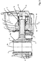
- the application force is transmitted either directly via the adjusting spindle 7 or, as in the illustrated embodiment, via an inserted into the adjusting spindle 7 pressure piece 8 on the application-side brake pad 10. Therefore, upon actuation of the rotary lever 6, the brake pad 10 is displaced and pressed against the brake disc 2 after overcoming the (target) clearance L.
- a closure lid 21 On the brake disc side of all functional parts in its interior receiving caliper 3 is closed by a closure lid 21, wherein the passage opening in the closure cap for the adjusting spindle 7 is sealed by at least one pleated sleeve 22.
- the caliper interior is closed on this side and protected against, for example, environmental influences.
- the completely pre-assembled assembly of the Nachstellgetriebes is generally designated by the reference numeral 11. She is in the FIGS. 1 and 2 shown in the starting position with new brake pads 10.
- the adjusting mechanism 11, which is screwed directly onto the adjusting spindle 7, is located in the position behind the displaceable element 5. Between a front face 15f of the adjusting gear 11 and an end face 5a of the displaceable element 5 there is a function clearance X as clearance.
- the function clearance X is greater than the maximum possible readjustment step or travel of the screwing out adjustment spindle 7 during a readjustment process. It should be noted that the magnitudes L, X shown in the figures are illustrative only and are actually dependent on the size of the respective type of brake.
- a brake ring 19 is shown schematically, which exerts a constant friction or holding torque on the adjusting spindle 7 and thus prevents unwanted rotational movements of the adjusting spindle 7.
- the brake ring 19 is held on the displaceable element 5.
- FIGS. 1 and 2 show the new condition of the brake pads 10 and the brake disc 2 with corresponding part position in the brake interior
- FIG. 3 shows the condition with worn brake pads 10 with correspondingly changed part position.
- a comparison of FIG. 3 with the FIGS. 1 and 2 makes it clear how the adjusting spindle 7 was unscrewed as a result of Nachstell intimide or - movements in the direction of the brake disc 2 from the displaceable element 5 and relative to the Nachstellgetriebe 11, wherein all other parts positions are retained.
- a decisive advantage of the Nachstellgetriebes shown here is also in terms of brake safety.
- a function opening 23 is provided on the rear side of the brake, via which the adjusting spindle 7 can be screwed back into its starting position in a manner which can not be explained in more detail here and with suitable means. After completed coating change the parts position is then again as in the FIGS. 1 and 2 shown.
- the functional opening 23 is sealed by suitable means.
- FIG. 4 schematically shows how the acting as a one-way clutch - and the operative connection with the assembly Nachstellgetriebe 11 producing - wrap spring 14, the cantilevered ends 14a, 14b, rests positively in the external thread 7a of the adjusting spindle 7. This detail is no longer clearly visible mounted.
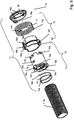
- FIG. 5 shows in an exploded view, the Nachstellgetriebe 11 with the parts that are assigned to a drive portion 12 and a driven portion 13.
- To the drive portion 12 includes a grooved ring 16.
- To the driven portion 13 includes the wrap spring 14, a guide sleeve 15 and connected to this drive plate 18, wherein the compound friction, material, force and / or form-fitting may be formed.
- a torsion spring 17 is located between the drive region 12 and the output region 13.
- suitable material selection it is also possible with suitable material selection to produce the guide sleeve 15 in one piece with the driver disk 18 with the required functional contours.
- the further part assembly such as mounting / mounting of the torsion spring 17 and the Nutrings 16 these parts must be designed accordingly while maintaining their basic functions.
- the guide sleeve 15 receives in its interior the wrap spring 14, wherein the wrap spring 14 is positioned axially fixed in / on functionally predetermined insertion and / or holding areas of the guide sleeve 15. This is on the guide sleeve 15 on the one hand, a radial projection or projection 15 b available.
- a protruding spring end 14a of the wrap spring 14 engages in a holding opening here, or the end 14a of the wrap spring 14 surrounds the projection 15b in the form of a loop so as to be coupled thereto in the circumferential direction.
- the other protruding end 14b of the wrap spring 14 engages in a relatively circumferentially extending longitudinal opening 15c of the guide sleeve 15.
- the wrap spring 14 and the guide sleeve 15 are coupled together. So that the in the external thread 7a of the adjusting spindle 7 intercalating spring 14 transmits the positive engagement not only on the guide sleeve 15, but even more efficient on the assembly Nachstellgetriebe 11, in the embodiment shown in the drawing in the guide sleeve 15 is a helical groove 15a with one of Slope of the wrap corresponding pitch formed. It serves the reliable contact system.
- the guide sleeve 15 can also have inwardly lying teilumflindliche and the thread path of the adjusting spindle 7 corresponding projections / projections 15g, which engage in the external thread 7a of the adjusting spindle 7.
- projections / projections 15g are spaced apart in the axial direction such that the wrap spring 14 can intervene therebetween for engagement in the external thread 7a, with or without helical groove 15a.
- the wrap spring 14 is relieved of axial guides.
- the axial positive engagement of the guide sleeve 15 on the external thread 7a takes place directly by means of the projections / projections 15g.
- This type of indirect and / or direct storage can be combined as required.
- a radial functional clearance is present, so that the wrap spring 14 can sufficiently expand in the opening or loosening direction. As a result, the smooth running of the Nachstellgetriebes 11 is ensured in this direction.
- a radial extension 15b of the guide sleeve 15 is formed in the circumferential direction stop surface 15e, whose function will be explained later.
- the close-sided conclusion of the guide sleeve 15 forms a circumferential radial collar whose end face 15f in the installed state of the end face 5a of the axially displaceable element 5 is opposite, wherein between the already explained above function game X is formed.
- the drive plate 18 is fixed in the completion of the Nachstellgetriebes 11 stationary. Depending on the design, this may be a frictional, material, non-positive or positive connection.
- circumferential profile openings 15d are provided on the guide sleeve 15 and locking projections 18a on the drive plate 18 in order to lock the two parts together like a bayonet.
- the drive plate 18 on a radially projecting projection 18b.
- the rotatably mounted on the guide sleeve 15 groove ring 16 has (in the drawing on the left) on a circumferentially extending elongated recess 16a, which forms (in the drawing below) a stop surface 16b.
- the recess 16a is dimensioned such that it engages therein a radial extension 15b with a stop surface 15e of the guide sleeve 15.
- the two stop surfaces 15e and 16b are on the one hand together.
- a relative rotation of the Nutrings 16 on the guide sleeve 15 corresponding to the length of the recess 16 a is possible.
- the grooved ring 16 also has a radial projection 16e, which on the one hand serves for the form-fitting mounting / holding of an angled spring end 17a of the torsion spring, and on the other hand is spaced from the holding area an axial groove 16f with groove walls 16g, 16h.
- axial groove 16f engages the NachstellInstitut für already mentioned driving pin 20 a.
- a further elongate recess 16c is provided in the groove ring 16, in the opening region of which the opening 15c of the guide sleeve 15 penetrates the end 14b of the wrap spring 14.
- This length is also dimensioned such that a relative rotation of the Nutrings 16 on the guide sleeve 15 corresponding to the length of the recess 16c is possible. Conversely, it is also possible if the abutment surface 16d presses against the spring leg 14b in the sense of an opening of the wrap spring 14.
- the torsion spring 17 is installed behind the retaining areas 16e, 18b by means of its spring ends 17a, 17b and under a corresponding pretensioning angle.
- the guide sleeve 15 are biased against each other at the stop surfaces 15e, 16b on the one hand.
- the parts or functional areas of the adjusting gear 11 which serve for the pretensioning and readjustment in the assembled state such as, for example, the parts 15e, 16a, b, e, f, 17a, b and 18b in the circumferential direction in structurally predetermined dimensions and / or angular positions are mutually or lie.
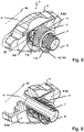
- the self-supporting and preassembled module of the Nachstellgetriebes 11 shows the FIG. 6 where also the axial groove 16f is shown with the walls 16g, 16h.
- the adjusting gear 11 is positively screwed by means of the wrap spring 14 to the adjusting spindle 7 with the external thread 7a. Subsequently, after the FIGS. 8, 9 the installation / screwing the adjusting spindle 7 with the adjusting gear 11 in the displaceable element. 5
- the mounting positions / distances of the individual components to one another are dimensioned such that both the alignment of the axial groove 16f and the functional clearance X required for the unimpeded adjustment process can be preset for complete assembly with further parts of the application device.
- the installation and functional layers show the FIGS. 1 . 2 , Reference is made to the above explanations.
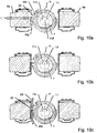
- the grooved ring 16 rotates the drive sleeve 18 connected to the guide sleeve 15, so that between the guide sleeve 15 and the external thread 7a the adjusting spindle 7 fitting wrap 14 transmits the torque to the adjusting spindle 7 because of their rotation in the reverse direction.
- the adjusting mechanism 11 follows in the adjustment direction 11n while reducing the functional clearance X of the movement of the adjusting spindle 7 synchronously.
- the driving pin 20 moves in the release direction 20l and rotates the grooved ring 16 back to the starting position while striking the groove wall 16h. Since the frictional torque M1 acting on the adjusting spindle 7 from the brake ring 19 is greater than the freewheeling moment M3 of the wrap spring 14 is, the wrap 14 with the remaining parts of the Nachstellgetriebes 11 in the loosening direction 11l on the non-co-rotating adjusting spindle 7 is rotated back until it returns to its original position with the function game X.
- the torsion spring 17 Since in the embodiment shown in the drawing, the torsion spring 17 is designed degressive, only a relatively small increase in the spring torque is generated by the overstroke. However, the biasing torque M4 of the torsion spring 17 due to its contraction / deformation in the final position is lower than the minimum necessary and transferable locking torque M5 of the wrap spring 14 with respect to the adjusting spindle. 7
- torsion spring 17 in the embodiment shown in the drawing stores energy in the return stroke of the rotary lever 6 by relaxing an adjusting movement via the Nachstellgetriebe 11 on the adjusting spindle 7 until the parts of the Nachstellgetriebes 11th are braced again in the preloaded initial state and the abutment surfaces 15e and 16b abut each other.
- the guide sleeve 15, the U-ring 16 and the drive plate 18 may be made of the same or different materials, such as metal, sheet metal parts, sintered material and / or plastic.
- the adjusting gear according to the invention can also be used in a two- or multi-spindle brake.
- each adjusting spindle can be equipped with its own adjusting gear.
- the Nachstellterrorism of only a single adjusting gear by means of appropriate synchronizing device on the other adjusting spindle are transmitted concurrently.
Description
Die Erfindung betrifft eine Scheibenbremse, insbesondere für Nutzfahrzeuge, mit einer Bremsscheibe, einem Bremssattel, mindestens einer auf einer Seite der Bremsscheibe innerhalb des Bremssattels liegenden Zuspanneinrichtung, einer axial verschieblichen Einrichtung, die bei Betätigung der Bremse einen Bremsbelag mittels mindestens einer Stellspindel axial in Richtung der Bremsscheibe verschiebt, wobei die Stellspindel drehbar ist, ein Außengewinde aufweist und in eine Gewindebohrung in der verschieblichen Einrichtung eingeschraubt ist, und mit einem Nachstellgetriebe, das um eine parallel zur Drehachse der Bremsscheibe liegende Achse verdrehbar ist und bei Verdrehen in einer ein Nachstellen bewirkenden ersten Drehrichtung wegen einer in dieser Drehrichtung wirkenden Drehkopplung die Stellspindel verdreht.The invention relates to a disc brake, in particular for commercial vehicles, with a brake disc, a brake caliper, at least one lying on one side of the brake disc within the brake caliper application device, an axially displaceable device, the brake pad by means of at least one adjusting spindle axially in the direction of the brake when the brake is actuated Disc rotates, wherein the adjusting spindle is rotatable, has an external thread and is screwed into a threaded bore in the displaceable device, and with a Nachstellgetriebe which is rotatable about an axis parallel to the axis of rotation of the brake disc axis and upon rotation in a readjusting effecting first direction of rotation because of an acting in this direction of rotation rotary coupling the adjusting screw twisted.
Derartige Scheibenbremsen sind in der Regel pneumatisch oder elektromechanisch betätigbar.Such disc brakes are usually actuated pneumatically or electromechanically.
Generell sind Verschleißnachstellvorrichtungen in unterschiedlichen Ausführungen bekannt, beispielsweise mechanische Nachstellungen, wie sie heute in gängigen Nutzfahrzeugscheibenbremsen für ein in bestimmten Grenzen konstantes Lüftspiel sorgen. Da die Nachstellungen unter allen Fahr- und Bremssituationen ein konstantes Lüftspiel aufrechterhalten müssen, sind die Anforderungen an die Präzision derartiger Nachstellungen sehr hoch. Es bestimmt nämlich insbesondere das Lüftspiel, das bis zur Belaganlage überwunden werden muß, den Schwenkweg beispielsweise eines zur Zuspannung dienenden Drehhebels und somit die maximal aufzubringende Bremskraft bzw. die Bremskraftreserve.In general, wear adjusting devices are known in different versions, for example, mechanical adjustments, as they provide today in common commercial vehicle disc brakes for a constant within certain limits clearance. Since the adjustments must maintain a constant clearance under all driving and braking situations, the demands on the precision of such adjustments are very high. It determines in particular the clearance, which must be overcome to the pad system, the pivoting example, a serving for tensioning rotary lever and thus the maximum applied braking force and the brake power reserve.
Bei solchen mit einer Nachstellvorrichtung ausgerüsteten Scheibenbremsen wird bei Bremsbetätigung und einem gegenüber einem Sollwert veränderten Lüftspiel die Nachstellvorrichtung aktiviert, beispielsweise durch ein Zustellelement einer Zuspanneinrichtung der Scheibenbremse. Tritt also ein Verschleiß von Bremsbelägen und/oder der Bremsscheibe mit einer daraus resultierenden Veränderung (Vergrößerung) des Lüftspiels auf, so erfolgt ein selbsttätiges Nachstellen der Beläge mittels der Nachstellvorrichtung, beispielsweise durch eine Verstellbewegung von Druckstempeln. Ein konstruktiv vorgegebenes Lüftspiel ist in Form fester geometrischer Größen in den am Nachstellvorgang beteiligten Bauelementen abgebildet.In such equipped with an adjusting disc brakes the adjusting device is activated during braking and a comparison with a setpoint clearance, for example, by a feed element of an application device of the disc brake. So if wear of brake pads and / or the brake disc with a resulting change (increase) of the clearance, so there is an automatic readjustment of the pads by means of the adjusting device, for example by an adjustment of pressure punches. A structurally predetermined clearance is depicted in the form of fixed geometric variables in the components involved in the adjustment process.
Aus der
Bei den oben genannten bekannten Scheibenbremsen ist die Nachstellvorrichtung am bremsscheibenabgewandten Endbereich der drehbar und mit einem Druckbund versehenen Nachstellmutter ortsfest gehalten. Da die Nachstellmutter selbst ebenfalls ortsfest in dem verschiebbaren Element gelagert ist, folgt die Nachstellvorrichtung den Axialbewegungen des verschiebbaren Elements bei Zuspannbewegungen.In the above known disc brakes the adjusting device is held stationary on the brake disc remote end portion of the rotatable and provided with a pressure collar adjusting nut. Since the adjusting nut itself is also stationarily mounted in the displaceable element, the adjusting device follows the axial movements of the displaceable element during application movements.
Der Begriff "ortsfest" bezieht sich auf die Position der Nachstellvorrichtung sowohl bei unbetätigter Bremse, als auch bei betätigter Bremse und während der Nachstellung selbst.The term "stationary" refers to the position of the adjuster both when the brake is not applied and when the brake is applied and during the adjustment itself.
Die zur Nachstellung gehörenden Teile sind funktionsmäßig in einen Antriebs- und einen Abtriebsbereich zu unterteilen, wobei der Antriebsbereich mit dem Drehhebel zur Drehmitnahme gekoppelt ist. Über eine als Einwegkupplung wirkende Schlingfeder wird die Drehbewegung auf den Abtriebsbereich übertragen, der über eine federbelastete und somit last- bzw. drehmomentabhängig wirkende mechanische Trennkupplung/Trenneinrichtung die Verdrehung der Nachstellmutter bewirkt. Bei der Trennkupplung/Trenneinrichtung handelt es sich beispielsweise um einen Reibkonus. Da die in die drehbare Nachstellmutter eingeschraubte Druck- bzw. Stellspindel verdrehfest gehalten ist, wird sie in Richtung der Bremsscheibe herausgeschraubt. Der Nachstellschritt wird beendet, wenn aufgrund des Krafthubes die Reibung in der Nachstellmutterlagerung bzw. Gewindepaarung ansteigt und das maximal mögliche Nachstellmoment übersteigt. Die drehmomentabhängige Kupplung rutscht dann durch, wodurch elastische Bremsenverformungen während des Krafthubes nicht in den Nachstellweg einfließen können.The parts belonging to the adjustment are functionally divided into a drive and an output range, wherein the drive portion is coupled to the rotary lever for rotational drive. About a acting as a one-way coil wrap the rotary motion is transmitted to the output range, which causes the rotation of the adjusting nut via a spring-loaded and thus load or torque-dependent mechanical separating clutch / separator. The separating clutch / separating device is, for example, a friction cone. Since the screwed into the rotatable adjusting nut pressure or adjusting spindle is held against rotation, it is unscrewed in the direction of the brake disc. The adjustment step is terminated when due to the power stroke, the friction in the Nachstellmutterlagerung or thread pairing increases and exceeds the maximum possible Nachstellmoment. The torque-dependent clutch then slips through, so that elastic Bremsenverformungen can not be incorporated into the Nachstellweg during the power stroke.
Bei den oben beschriebenen bekannten Bremsen liegen die zur Nachstellung gehörenden Teile in Axialrichtung gesehen hintereinander und sind ortsfest mit dem verschiebbaren Element verbunden. Dies erfordert eine entsprechende Einbaulänge in Axialrichtung. Da weiterhin die Zuspannteile, also die Nachstellmutter und die Druckspindel, entsprechenden Bauraum in Anspruch nehmen, ist eine Vergrößerung der Teile zur Erzielung von höheren Zuspannkräften bedingt durch die vorgegebene Sattelkontur nicht möglich. Zudem können in allen Nachstellvorrichtungen die die federbelastete mechanische Trenneinrichtung bildenden Nachstellsteile einem relativen Verschleiß in den Kontaktbereichen unterliegen, was die Nachstellgenauigkeit beeinflußt.In the known brakes described above, the parts belonging to the adjustment are seen in succession in the axial direction and are fixedly connected to the displaceable element. This requires a corresponding installation length in the axial direction. Since continue the Zuspannteile, so the adjusting nut and the pressure spindle, take appropriate space, an enlargement of the parts to achieve higher application forces due to the predetermined saddle contour is not possible. In addition, in all adjusters the spring-loaded mechanical separator forming adjusting parts are subject to relative wear in the contact areas, which affects the Nachstellgenauigkeit.
Aus der
Bei dieser bekannten-Bremse ist die Gesamtheit der als Drehantrieb dienenden Nachstellvorrichtung in Axialrichtung länglich bzw. röhrenförmig als zusammenhängende Baugruppe ausgeführt. Diese wird durch eine der Bremsscheibe abgewandte Sattelöffnung ins Sattelinnere verbracht und dort ortsfest am Sattelende befestigt, so daß sie sich in eine Öffnung der Stellspindel hinein erstreckt. Der Drehantrieb liegt daher konzentrisch innerhalb der hohlen Drehspindel. Dabei ist der Drehantrieb bzw. dessen Abtriebsteil undrehbar, aber axial verschiebbar mit der Stellspindel über axiale Profilierungen gekoppelt. Damit werden die Drehbewegungen des Nachstellers auf die Stellspindel übertragen. Mit zunehmender Verschleißnachstellung wird die Stellspindel in Richtung des Bremsbelages bzw. der Bremsscheibe aus dem verschiebbaren Element herausgeschraubt und somit auch gegenüber der ortsfesten Nachstellung axial verschoben. Als momentenabhängige Trenneinrichtung dienen innerhalb der Nachstellerbaugruppe Reibkupplungen oder Zahngesperre, die jeweils federbelastet sind und mechanisch wirken.In this known brake, the entirety of serving as a rotary drive adjusting device in the axial direction elongated or tubular designed as a coherent assembly. This is spent by a brake disc facing away from the saddle opening into the saddle interior and there fixedly attached to the saddle end, so that it extends into an opening of the adjusting spindle. The rotary drive is therefore concentric within the hollow rotary spindle. In this case, the rotary drive or its driven part is non-rotatably but axially displaceably coupled to the adjusting spindle via axial profiles. Thus, the rotational movements of the adjuster are transmitted to the adjusting spindle. With increasing wear adjustment, the adjusting spindle is unscrewed in the direction of the brake pad or the brake disc from the displaceable element and thus axially displaced with respect to the stationary adjustment. As a torque-dependent separator serve within the Nachstellerbaugruppe friction clutches or ratchet, each of which is spring loaded and act mechanically.
Da bei der Bremse nach der
Zu der Bremse nach dem
Eine ähnliche Scheibenbremse wie das
Sowohl die Bremse nach dem
Die Scheibenbremse nach der
Die
Die
Die Erfindung geht aus von der aus der
Erfindungsgemäß wird die gestellte Aufgabe bei einer Scheibenbremse der eingangs genannten Art dadurch gelöst, daß das Nachstellgetriebe eine Gewindeeinrichtung aufweist, die zumindest bei einem Verdrehen in einer der ersten Drehrichtung entgegengesetzten zweiten Drehrichtung mit dem Außengewinde der Stellspindel kämmt und das Nachstellgetriebe bezüglich der Stellspindel verschraubt.According to the invention the object is achieved in a disc brake of the type mentioned above in that the adjusting gear has a threaded device which meshes with the outer thread of the adjusting spindle at least during rotation in one of the first rotational direction opposite second direction of rotation and screwed the adjusting gear with respect to the adjusting spindle.
Mit anderen Worten wird das Nachstellgetriebe nicht wie bei den bekannten Bremsen ortsfest am Bremssattel oder ortsfest an dem verschiebbaren Element gehalten. Vielmehr erfolgt die Halterung/Lagerung direkt am/auf dem Gewindebereich der Stellspindel. Die Wirkverbindung wird unmittelbar über das Außengewinde der Stellspindel hergestellt. Bei den bekannten Scheibenbremsen erforderliche Befestigungen/Halterungen des Nachstellgetriebes an dem verschiebbaren Element oder an dem Bremssattel können mithin entfallen. Die Stellspindel selbst trägt das Nachstellgetriebe.In other words, the adjusting gear is not held stationary on the caliper or stationary on the displaceable element as in the known brakes. Rather, the holder / storage is directly on / on the threaded portion of the adjusting spindle. The operative connection is made directly via the external thread of the adjusting spindle. In the known disc brakes required fasteners / brackets of the Nachstellgetriebes on the displaceable element or on the brake caliper can therefore be omitted. The adjusting spindle itself carries the adjusting gear.
Wie bereits oben erwähnt ist erfindungsgemäß das Nachstellgetriebe unmittelbar auf der Stellspindel gehalten. Daher kann die Nachstellmutter entfallen. Dadurch wird die Bremse erheblich vereinfacht.As already mentioned above, according to the invention, the adjusting mechanism is held directly on the adjusting spindle. Therefore, the adjusting nut can be omitted. This considerably simplifies the brake.
Erfindungsgemäß bevorzugt ist die Gewindeeinrichtung eine Schlingfeder, die die gleiche Steigung wie das Außengewinde der Stellspindel hat. Diese Schlingfeder kann mithin zwei Funktionen gleichzeitig erfüllen. Zum einen dient sie dazu, das Nachstellgetriebe mit der Stellspindel verschraubbar zu machen, zumindest was die zweite Drehrichtung angeht. Zum anderen stellt sie eine Einwegkupplung dar, die sicherstellt, daß das Nachstellgetriebe bei einem Verdrehen in der ersten Drehrichtung mit der Stellspindel drehgekoppelt ist und daher die Stellspindel verdreht.According to the invention, the threaded device is preferably a wrap spring which has the same pitch as the external thread of the adjusting spindle. This wrap can thus fulfill two functions simultaneously. On the one hand, it serves to make the adjuster with the adjusting screw screwed, at least as regards the second direction of rotation. On the other hand, it represents a one-way clutch, which ensures that the adjusting gear is rotationally coupled with a rotation in the first direction of rotation with the adjusting spindle and therefore rotates the adjusting spindle.
Erfindungsgemäß weiter bevorzugt ist vorgesehen, daß zwei oder mehr Windungen der Schlingfeder mit dem Außengewinde der Stellspindel kämmen. Dadurch ist eine verläßliche Kopplung gegeben.According to the invention it is further preferred that two or more turns of the wrap spring mesh with the external thread of the adjusting spindle. This gives a reliable coupling.
Nach einer weiter bevorzugten Ausführungsform der Erfindung ist vorgesehen, daß ein Endabschnitt der Schlingfeder an einer Führungshülse des Nachstellgetriebes gehalten ist, vorzugsweise durch Formschluß. Dadurch ist eine besonders einfache Form der Kopplung der Schlingfeder mit der Führungshülse geschaffen.According to a further preferred embodiment of the invention, it is provided that one end portion of the wrap spring is held on a guide sleeve of the adjusting gear, preferably by positive engagement. This creates a particularly simple form of coupling of the wrap spring with the guide sleeve.
Die Führungshülse kann mindestens eine Gewindeeinrichtung aufweisen, die mit dem Außengewinde der Stellspindel kämmt. Mit anderen Worten kämmt nach dieser Ausführungsform nicht nur die Stellspindel (in der zweiten Drehrichtung) mit dem Außengewinde der Stellspindel, sondern auch die Führungshülse. Dadurch ist die Führungshülse noch sicherer auf der Stellspindel gehalten, ohne daß man sich auf die Schlingfeder allein verlassen müßte.The guide sleeve may have at least one threaded device which meshes with the external thread of the adjusting spindle. In other words, according to this embodiment, not only the adjusting spindle (in the second rotational direction) meshes with the external thread of the adjusting spindle, but also the guide sleeve. As a result, the guide sleeve is held even safer on the adjusting spindle without having to rely on the wrap spring alone.
Die Schlingfeder liegt erfindungsgemäß weiter bevorzugt radial außen in einer Wendelnut. Dadurch ist sichergestellt, daß die Schlingfeder, die einerseits axial mit der Stellspindel gekoppelt ist, andererseits auch axial mit den übrigen Teilen des Nachstellgetriebes gekoppelt ist, wodurch eine insgesamt verläßliche Axialkopplung des gesamten Nachstellgetriebes mit der Stellspindel sichergestellt ist.The wrap is according to the invention further preferably radially outside in a helical groove. This ensures that the wrap spring, on the one hand axially coupled to the adjusting spindle, on the other hand, is also coupled axially with the other parts of the Nachstellgetriebes, whereby a total reliable axial coupling of the entire Nachstellgetriebes is ensured with the adjusting spindle.
Erfindungsgemäß weiter bevorzugt ist vorgesehen, daß das Nachstellgetriebe um mindestens eine Strecke axial verschieblich ist, die der maximalen Nachstellstrecke pro Nachstellschritt entspricht. Diese Ausgestaltung stellt sicher, daß das Nachstellgetriebe in keinem denkbaren Betriebszustand infolge von Axialverschiebungen irgendwo anschlägt.According to the invention it is further preferred that the adjusting gear is axially displaceable by at least one distance, which corresponds to the maximum readjustment distance per adjustment step. This embodiment ensures that the Nachstellgetriebe in any conceivable operating state as a result of axial displacements somewhere strikes.
Erfindungsgemäß weiter bevorzugt kann eine einem Verdrehen der Stellspindel entgegenwirkende Bremseinrichtung vorgesehen sein. Eine solche Bremseinrichtung dient zum einen dem Festhalten der Stellspindel während der Verschraubbewegungen des Nachstellgetriebes in der zweiten Drehrichtung. Zum anderen dient die Bremseinrichtung der Vermeidung von (ungewollten) Verstellungen infolge von Vibrationen und Rütteln auf Schlechtwegstrecken.According to the invention, a braking device counteracting a rotation of the adjusting spindle may be provided. Such a braking device serves on the one hand to hold the adjusting spindle during Verschraubbewegungen the Nachstellgetriebes in the second direction. On the other hand, the braking device is used to avoid (unwanted) adjustments due to vibration and jogging on poor roads.
Das Nachstellgetriebe weist erfindungsgemäß weiter bevorzugt wenigstens eine Nut auf, deren Weite einem Solllüftspiel entspricht. Bei Scheibenbremsen, die mittels eines Drehhebels zugespannt werden, nimmt die Nut einen Mitnahmestift auf, der zum Verdrehen des Nachstellgetriebes beim Bremsen dient. Das Spiel des Mitnahmestiftes in der Nut bestimmt dabei das Lüftspiel.The adjusting gear according to the invention further preferably at least one groove whose width corresponds to a desired clearance. In disc brakes, which are applied by means of a rotary lever, the groove receives a driving pin, which serves to rotate the Nachstellgetriebes during braking. The game of driving pin in the groove determines the clearance.
Nach einer weiter bevorzugten Ausführungsform der Erfindung weist das Nachstellgetriebe einen Antriebsbereich und einen Abtriebsbereich sowie eine zwischen den beiden Bereichen liegende momentenabhängige Kupplung auf. Die momentenabhängige Kupplung stellt dabei einen Überlastschutz dar.According to a further preferred embodiment of the invention, the adjusting gear has a drive region and an output region as well as a torque-dependent coupling lying between the two regions. The torque-dependent coupling represents an overload protection.
Erfindungsgemäß bevorzugt weist die momentenabhängige Kupplung eine Torsionsfeder auf.According to the invention, the torque-dependent coupling preferably has a torsion spring.
Die Torsionsfeder ist erfindungsgemäß weiter bevorzugt vorgespannt.The torsion spring is inventively further biased.
Schließlich ist es erfindungsgemäß bevorzugt vorgesehen, daß die Torsionsfeder dazu ausgelegt ist, im Bremsüberhub Energie zu speichern und damit im Lösehub die Stellspindel im Sinne einer Nachstellung zu verstellen. Durch diese Ausgestaltung ist es möglich, bei größerem Verschleiß schneller wieder das Solllüftspiel zu erreichen, einfach weil nicht nur im Bremshub, sondern zusätzlich auch im Lösehub eine Nachstellung erfolgt.Finally, it is preferably provided according to the invention that the torsion spring is designed to store energy in Bremsüberhub and thus adjust the adjusting spindle in the release stroke in terms of readjustment. With this configuration, it is possible, with greater wear faster again the Solllüftspiel to achieve, simply because not only in the brake stroke, but also in the release stroke an adjustment takes place.
Wie bereits oben ausgeführt ist erfindungsgemäß bevorzugt das Nachstellgetriebe in wenigstens zwei Funktionsbereiche unterteilt, nämlich einen Antriebsbereich und einen Abtriebsbereich. Die beiden Bereiche liegen bevorzugt konzentrisch zueinander und sind miteinander derart gekoppelt, daß sie einander nicht nur radial, sondern auch axial tragen. Somit stellt das Nachstellgetriebe eine vormontierte kompakte Baugruppe dar. Dadurch kann im Vergleich mit herkömmlichen Bremsen, wo die einzelnen Nachstellteile axial im Sattelinneren hintereinander liegen, Bauraum eingespart werden. Weiterhin sind keine Halterungen bzw. Befestigungsteile, wie beispielsweise Bremssattelbereiche, mehr nötig, um die einzelnen Teile miteinander in Umfangsrichtung und axial zu verbinden bzw. zu koppeln.As already stated above, according to the invention, the adjusting gear is preferably subdivided into at least two functional areas, namely a drive area and an output area. The two areas are preferably concentric with each other and are coupled together so that they not only support each other radially, but also axially. Thus, the Nachstellgetriebe represents a preassembled compact assembly. This can be saved in comparison with conventional brakes, where the individual adjusting axially in the saddle inside one another, space. Furthermore, no brackets or fastening parts, such as caliper areas, more necessary to connect or couple the individual parts together in the circumferential direction and axially.
Bevorzugt wird die Wirkverbindung zwischen der Stellspindel und dem Nachstellgetriebe auf dem der Bremsscheibe abgewandten Gewindebereich der Stellspindel realisiert, der sich aus dem verschiebbaren Element hinaus ins Sattelinnere erstreckt. Die dadurch erzielte Einsparung an Bauraum kann für großzügigere Dimensionierungen der einzelnen Teile und/oder für zusätzliche Funktionsteile genutzt werden.Preferably, the operative connection between the adjusting spindle and the adjusting gear is realized on the threaded portion of the adjusting spindle facing away from the brake disk, which extends out of the displaceable element into the interior of the saddle. The resulting savings in space can be used for more generous dimensions of the individual parts and / or for additional functional parts.
Bevorzugt ist das Nachstellgetriebe in Funktionsstellung über seinen Abtriebsbereich in Axialrichtung auf dem Gewindebereich der Stellspindel durch Formschlüssigkeit derart festgelegt, daß zumindest in demjenigen Betriebszustand, in dem kein Nachstellschritt vollzogen wird, immer eine definierte Abstandsposition gegenüber dem verschiebbaren Element vorliegt. Durch ein Funktionsspiel zwischen einschlägigen zueinander weisenden Flächen des verschiebbaren Elements einerseits und des Nachstellgetriebes andererseits können auch keine die Nachstellung beeinflussenden (Haft-)Reibungen durch Verspannungen seitens der Halterung usw. auftreten.Preferably, the Nachstellgetriebe is set in functional position over its output range in the axial direction on the threaded portion of the adjusting spindle by positive engagement such that there is always a defined distance position relative to the displaceable element, at least in that operating state in which no adjustment step is performed. By a function match between relevant mutually facing surfaces of the movable element on the one hand and the Nachstellgetriebes on the other hand, no repercussion affecting (adhesive) friction due to tension on the part of the holder, etc. occur.
Die Wirkverbindung des Nachstellgetriebes mit der Stellspindel zur Einstellung des Solllüftspiels ist derart ausgelegt, daß bei Lüftspielvergrößerung infolge Belagverschleißes der erforderliche Nachstellschritt bei und/oder nach einer Bremsenbetätigung erfolgen kann.The operative connection of the Nachstellgetriebes with the adjusting spindle for setting the Solllüftspiels is designed so that at Lüftspielvergrößerung due to lining wear the required Nachstellschritt can occur at and / or after a brake application.
Dafür ist bevorzugt das Nachstellgetriebe mittels einer als Einwegkupplung dienenden Schlingfeder mit dem Gewindebereich der Stellspindel gekoppelt, wobei weiterhin die Schlingfeder mit vorzugsweise mindestens zwei Umschlingungen formschlüssig im Gewindeprofil der Stellspindel einliegt. Da die Schlingfeder formschlüssig und drehrichtungsabhängig in Sperrrichtung - also bei einem erforderlichen Nachstellschritt - wirkt, wird die Stellspindel in Richtung Bremsscheibe aus der Gewindebohrung des verschiebbaren Elements herausgeschraubt, wobei die Schlingfeder - und somit das gesamte Nachstellgetriebe - diese Axialverschiebung infolge der Drehung und entsprechend der Nachstellgröße mitvollzieht. Mit anderen Worten vollziehen die Stellspindel und das Nachstellgetriebe beim Nachstellschritt synchrone Bewegungen.For this purpose, the adjusting gear is preferably coupled by means of a wrap-around serving as a wrap spring with the threaded portion of the adjusting spindle, wherein further the wrap spring rests with preferably at least two wraps in a form-fitting manner in the thread profile of the adjusting spindle. Since the wrap spring positively and in the direction of rotation in the reverse direction - that is at a Nachstellschritt - acts, the adjusting spindle is unscrewed in the direction of brake disc from the threaded bore of the displaceable element, the wrap - and thus the entire Nachstellgetriebe - this axial displacement due to the rotation and according to the readjustment responding to excursions. In other words, the adjusting spindle and the adjusting gear perform synchronous movements during the adjustment step.
Damit das über die Schlingfeder auf die Stellspindel aufgeschraubte Nachstellgetriebe bei dieser Ausschraubbewegung nicht an dem verschiebbaren Element anschlägt und somit blockiert wird, ist das bereits oben genannte Funktionsspiel als Abstand zwischen den zueinanderliegenden Flächen des Nachstellgetriebes einerseits und des verschiebbaren Elements andererseits bevorzugt größer als der maximal mögliche Nachstellschritt bzw. -weg.Thus, the screwed over the wrap on the adjusting screw adjusting mechanism in this unseating abuts against the sliding element and thus blocked, the above-mentioned function game as the distance between the mutually facing surfaces of the adjusting mechanism on the one hand and the displaceable element on the other hand is preferably greater than the maximum possible Adjustment step or path.
Somit liegt über die Formschlüssigkeit und in Sperrrichtung der Schlingfeder eine "schwimmende" Lagerung des Nachstellgetriebes mittels der Stellspindel vor.Thus, there is a "floating" bearing of the adjusting by means of the adjusting spindle on the positive locking and in the reverse direction of the wrap.
"Schwimmend" im obigen Sinne bedeutet, daß das Nachstellgetriebe der Stellspindel zumindest über den Weg des jeweiligen Nachstellschrittes synchron folgt. Dabei verkleinert sich (vorübergehend) das oben genannte Funktionsspiel."Floating" in the above sense means that the adjusting of the adjusting spindle follows synchronously at least over the path of the respective Nachstellschrittes. This reduces (temporarily) the above function game.
Ist der Nachstellschritt vollzogen und der Bremsvorgang beendet, bewegen sich die Zuspann- und Nachstellteile über die Rückstellkraft wenigstens einer Druckfeder wieder in ihre Ausgangsposition. Dabei wird das Nachstellgetriebe in Freilaufrichtung der Schlingfeder wieder in seine Ausgangsstellung und auf das oben genannte Funktionsspiel zurückgeschraubt. Damit sich dabei die Stellspindel nicht mit zurückschraubt, ist erfindungsgemäß bevorzugt ein Bremsring vorgesehen, der beispielsweise an dem verschiebbaren Element gehalten ist und mit konstantem Reibmoment auf die Stellspindel wirkt. Das dadurch auf das Außengewinde oder axial auf die Gewindeflanken der Stellspindel wirkende Reib- bzw. Haltemoment ist bevorzugt größer als das Löse- bzw. Freilaufmoment der sich öffnenden und im Gewinde einliegenden Schlingfeder. Da das genannte Reibmoment kontinuierlich wirkt, können auch beispielsweise bei Bremsenschwingungen usw. keine unerwünschten Drehbewegungen der Stellspindel mit unerwünschten Lüftspielveränderungen erfolgen.If the readjustment step is completed and the braking process is completed, the application and adjustment parts move back to their starting position via the restoring force of at least one compression spring. The Nachstellgetriebe is screwed back in the freewheeling direction of the wrap spring back to its original position and the above-mentioned functional game. So that thereby the adjusting spindle does not screw back, a brake ring according to the invention is preferably provided, which is held for example on the displaceable element and acts with constant friction torque on the adjusting spindle. The thereby acting on the external thread or axially on the thread flanks of the adjusting spindle friction or holding torque is preferably greater than the release or free-wheeling moment of the opening and inserted in the coil wrap. Since the said friction torque acts continuously, for example, in the case of brake vibrations, etc., no undesirable rotational movements of the adjusting spindle can take place with undesired changes in the clearance play.
Während das Nachstellgetriebe über den gesamten verschleißkompensierenden Nachstellweg (Bremsbelag/Bremsscheibe) in einer festgelegten und konstanten / freitragenden Position gegenüber dem verschiebbaren Element bleibt, wird die Stellspindel zunehmend in Richtung der Bremsscheibe herausgeschraubt, bis die Belagverschleißgrenze erreicht ist.While the Nachstellgetriebe remains over the entire wear compensating Nachstellweg (brake pad / brake disc) in a fixed and constant / cantilevered position relative to the displaceable element, the adjusting spindle is increasingly unscrewed in the direction of the brake disc until the pad wear limit is reached.
Die als Einwegkupplung wirkende Schlingfeder ist erfindungsgemäß bevorzugt innen einliegend in einem dem Nachstellgetriebe zugehörigen hülsenförmigen Abtriebsbereich (nachfolgend als Führungshülse bezeichnet) angeordnet, wobei hier erfindungsgemäß weiter bevorzugt mindestens an einem Schlingfederende ein Formschluß als Eingriff in eine Ausnehmung oder als Teilumschlingung von dem Federende an einem Ansatz/Vorsprung mit der Führungshülse besteht. Damit sind die beiden Teile umfänglich und axial aneinander festgelegt, weil die Schlingfeder aufgeschraubt / formschlüssig im Stellspindelgewinde einliegt.According to the invention, the wrap spring acting as a one-way clutch is preferably arranged inside in a sleeve-shaped output region (hereinafter referred to as guide sleeve) associated with the readjustment gear, wherein here according to the invention more preferably at least at one loop spring a form fit as engagement in a recess or as a partial loop of the spring end to a neck / Projection with the guide sleeve exists. Thus, the two parts are circumferentially and axially fixed to each other, because the wrap spring screwed / rests positively in the adjusting spindle thread.
Um die Positionierungen der Schlingfeder gegenüber dem Gewindebereich einerseits und der Führungshülse gegenüber der Schlingfeder andererseits noch weiter zu verbessern, weist erfindungsgemäß bevorzugt die Führungshülse eine der Gewindesteigung entsprechende Profilierung in Form einer Wendelnut auf, in der die Schlingfeder einliegt. Somit ist eine definierte Formschlüssigkeit untereinander hergestellt, die nicht nur die Funktionsgenauigkeit, sondern auch den Zusammenbau/das Aufschrauben des Nachstellgetriebes auf die Stellspindel bei der Erstmontage verbessert. Damit ist die Führungshülse mittelbar über die Schlingfeder auf dem Gewindebereich der Stellspindel positioniert.In order to further improve the positioning of the wrap spring relative to the threaded portion on the one hand and the guide sleeve relative to the wrap spring, the guide sleeve preferably has a profile corresponding to the thread pitch in the form of a helical groove in which the wrap spring rests. Thus, a defined positive engagement is established among each other, which not only improves the functional accuracy, but also the assembly / screwing of the Nachstellgetriebes on the adjusting spindle during initial assembly. Thus, the guide sleeve is positioned indirectly via the wrap spring on the threaded portion of the adjusting spindle.
Eine weitere Verbesserung der Halterung der Führungshülse in Axialrichtung bezüglich des Gewindebereichs der Stellspindel wird erfindungsgemäß weiter bevorzugt bei einliegender Schlingfeder durch den unmittelbaren Eingriff der Führungshülse in das von der Schlingfeder gebildete Gewinde erzielt, um gegebenenfalls Verspannungen bei Nachstell- und/oder Lösevorgängen aus dem Nachstellsystem herauszunehmen.A further improvement of the mounting of the guide sleeve in the axial direction with respect to the threaded portion of the adjusting spindle is achieved according to the invention more preferably with in-lying wrap by the direct engagement of the guide sleeve in the thread formed by the wrap, to remove any tension during readjustment and / or release operations from the adjustment ,
In diesem Falle weist dann die Führungshülse nach innen liegende, teilumfängliche und dem Gewindeverlauf der Stellspindel entsprechende Vorsprünge auf, die in das Gewinde der Stellspindel eingreifen. Die Vorsprünge sind axial gesehen bevorzugt so voneinander beabstandet, daß in deren Zwischenbereich die Schlingfeder für den Eingriff in das Gewinde einliegt, mit oder ohne Wendelnut. Dadurch wird die Schlingfeder von Axialführungen entlastet, weil die axiale Formschlüssigkeit der Führungshülse auf dem Gewinde der Stellspindel direkt mittels der Vorsprünge erfolgt.In this case, then, the guide sleeve has inwardly located, teilumfängliche and the thread path of the adjusting spindle corresponding projections which engage in the thread of the adjusting spindle. The projections are preferably axially spaced apart so that in the intermediate region of the wrap spring rests for engagement with the thread, with or without helical groove. As a result, the wrap spring is relieved of axial guides, because the axial form fit of the guide sleeve on the thread of the adjusting spindle directly by means of the projections.
Die oben beschriebenen Arten der mittelbaren und unmittelbaren Lagerung lassen sich je nach Bedarf beliebig miteinander kombinieren.The types of direct and indirect storage described above can be combined as desired with each other.
Als Antriebsbereich des Nachstellgetriebes dient erfindungsgemäß weiter bevorzugt ein weiteres hülsenförmiges Teil, das im Folgenden als Nutring bezeichnet ist. Der Nutring ist auf der Führungshülse relativ drehbar gelagert, wobei beide Teile bevorzugt endseitig derartige Konturen aufweisen, daß der Nutring auch axial auf der Führungshülse gehalten ist.According to the invention, a further sleeve-shaped part, which is referred to below as a groove ring, preferably serves as a drive region of the adjusting mechanism. The grooved ring is relatively rotatably mounted on the guide sleeve, both Parts preferably end have such contours that the U-ring is also held axially on the guide sleeve.
Der Nutring weist nach einer weiter bevorzugten Ausführungsform der Erfindung wenigstens einen axialen Nutbereich auf, der vorzugsweise radial auskragt und in den wenigstens ein mit einem der Zuspannung der Bremse dienenden Drehhebel bzw. einer solchen Bremswelle verbundener Mitnehmer, vorzugsweise ein Mitnahmestift, im Sinne einer Aktivierung des Nachstellgetriebes eingreift. In dem Anschlagspiel zwischen den Wandungen des wenigstens einen Mitnahmestifts und der wenigstens einen Axialnut wird das konstruktive Solllüftspiel vorgegeben. Die Vorgabe des Solllüftspiels kann aber auch zur weiteren Sicherstellung des Eingriffs durch zahnradähnliche Nutsegmente und mehrere beabstandete Mitnahmestifte erfolgen. Darüber hinaus ist es auch möglich, den Eingriff kinematisch umzukehren, sofern die geometrischen Verhältnisse dies erlauben. Dann wäre der Drehhebel bzw. die Bremswelle mit einer oder mehreren Nuten versehen, und der Nutring trüge einen oder mehrere Mitnahmestifte.According to a further preferred embodiment of the invention, the grooved ring has at least one axial groove area which projects radially and into the at least one driver associated with one of the brakes of the brake or such a brake shaft, preferably a driving pin, in the sense of activating the Nachstellgetriebes engages. In the stop play between the walls of the at least one driving pin and the at least one axial groove, the constructive Solllüftspiel is specified. The specification of the desired clearance can also be done to further ensure the engagement by gear-like groove segments and a plurality of spaced driving pins. In addition, it is also possible to kinematically reverse the intervention, if the geometric conditions allow it. Then, the rotary lever or the brake shaft would be provided with one or more grooves, and the U-ring carry one or more driving pins.
Um für einen Nachstellschritt eine von dem Nutring ausgehende Drehung über die Führungshülse auf die Schlingfeder - und somit auch auf die Stellspindel - zu übertragen, ist erfindungsgemäß bevorzugt auf dem Nutring ein elastisches Teil gelagert und mit dem Nutring und der Führungshülse unter Vorspannung derart gekoppelt, daß Nutring und Führungshülse über die Rückstellkraft des elastischen Teils in Umfangsrichtung gegeneinander an zueinander definierten Anschlägen verspannt werden. Bei dem elastischen Teil handelt es sich bevorzugt um eine Torsionsfeder, die mittels ihrer Federenden in vorgespanntem Zustand jeweils einen Nutringbereich und einen Führungshülsenbereich hintergreift.In order to transmit an outgoing from the grooved ring rotation of the sleeve ring on the wrap - and thus on the adjusting spindle - for an adjustment step, according to the invention preferably mounted on the grooved ring an elastic member and coupled with the grooved ring and the guide sleeve under bias such that U-ring and guide sleeve are clamped over the restoring force of the elastic member in the circumferential direction against each other to each other defined attacks. The elastic part is preferably a torsion spring, which in each case engages behind a U-ring area and a guide sleeve area by means of its spring ends in the prestressed state.
Erfindungsgemäß weiter bevorzugt ist die Torsionsfeder mit einem Radialspiel bezüglich denjenigen Bauteilen angeordnet, die ihrer Lagerung dienen, hier Nutring, Führungshülse oder eine zugehörige Mitnehmerscheibe. Dadurch kann es zu keinem Aufsetzen bzw. Blockieren des Federweges bei Torsionen kommen.According to the invention, the torsion spring is preferably arranged with a radial play with respect to those components which serve for its mounting, here groove ring, guide sleeve or an associated drive plate. As a result, it can come to no placement or blocking the spring travel in torsions.
Im Folgenden ist die Erfindung anhand bevorzugter Ausführungsbeispiele unter Bezugnahme auf die beiliegende Zeichnung mit weiteren Einzelheiten näher erläutert. Dabei zeigen
Figur 1- eine teilweise geschnittene Draufsicht auf eine Scheibenbremse nach einem bevorzugten Ausführungsbeispiel der Erfindung,
Figur 2- eine geschnittene Seitenansicht der Scheibenbremse,
Figur 3- die gleiche
Ansicht wie Figur 2 , jedoch mit verschlissenen Bremsbelägen und herausgeschraubter Stellspindel, Figur 4- schematisch die Stellspindel mit einliegender Schlingfeder,
Figur 5- eine Explosionsdarstellung des Nachstellgetriebes,
Figur 6- das Nachstellgetriebe als vormontierte Baugruppe,
Figur 7- eine schematische Schnittansicht der Stellspindel mit aufgeschraubtem Nachstellgetriebe,
Figur 8- eine schematische perspektivische Ansicht einer Baugruppe mit Zuspanneinrichtung und aufgeschraubtem Nachstellgetriebe in Ausgangsstellung,
Figur 9- die gleiche
Ansicht wie Figur 8 , jedoch teilweise geschnitten, Figur 10a bis 10cTeilschnittansichten aus Figur 1 in verschiedenen Funktionsstellungen,Figur 11- schematisch das Nachstellgetriebe in Normalstellung und
Figur 12- die gleiche
Ansicht wie Figur 11 , jedoch im Überlastbereich.
- FIG. 1
- a partially sectioned plan view of a disc brake according to a preferred embodiment of the invention,
- FIG. 2
- a sectional side view of the disc brake,
- FIG. 3
- the same view as
FIG. 2 , but with worn brake pads and unscrewed adjusting spindle, - FIG. 4
- schematically the adjusting spindle with enclosed wrap spring,
- FIG. 5
- an exploded view of the Nachstellgetriebes,
- FIG. 6
- the adjustment gear as a preassembled module,
- FIG. 7
- a schematic sectional view of the adjusting spindle with screwed-on adjusting gear,
- FIG. 8
- a schematic perspective view of an assembly with Zuspanneinrichtung and screwed Nachstellgetriebe in the starting position,
- FIG. 9
- the same view as
FIG. 8 , but partially cut, - FIGS. 10a to 10c
- Partial section views off
FIG. 1 in different functional positions, - FIG. 11
- schematically the Nachstellgetriebe in normal position and
- FIG. 12
- the same view as
FIG. 11 , but in the overload range.
Bei der in der Zeichnung dargestellten und mit dem Bezugszeichen 1 bezeichneten Scheibenbremse handelt es sich um eine pneumatisch oder elektromechanisch betätigte Scheibenbremse, deren Bremssattel 3 eine Bremsscheibe 2 umgreift. Beidseits der Bremsscheibe 2 sind Bremsbeläge 10 mit jeweils einem Bremsbelagträger 10a vorgesehen. Eine Zuspanneinrichtung ist allgemein mit der Bezugsziffer 4 bezeichnet. Sie ist hier einseitig im Bremssattel 3 angeordnet, bei dem es sich um einen Gleitsattel oder um einen Festsattel handeln kann. Zu der Zuspanneinrichtung 4 gehört ein Drehhebel 6, der mit einer parallel zur Hauptebene 2a der Bremsscheibe 2 im Bremssattel 3 angeordneten Zuspann- bzw. Bremswelle 6a verbunden ist. Ferner ist ein sich ebenfalls quer zur Bremsscheibenebene 2a erstreckendes und im Bremssattel 3 geführtes verschiebbares Element 5 vorgesehen. Der Drehhebel 6 stellt die Verbindung zwischen einer eine Kraft einleitenden Betätigungseinrichtung (nicht gezeigt) und der Bremswelle 6a dar. Die Bremsenachse liegt parallel zu der Hauptachse (nicht gezeigt) der Bremsscheibe 2 und ist mit der Bezugszahl A-B bezeichnet.In the illustrated in the drawing and designated by the
Wird der Drehhebel 6 in hier nicht näher zu erläuternder Weise durch eine am Bremssattelende befestigte Betätigungseinrichtung mittels beispielsweise einer eine Funktionsöffnung durchdringenden Druckstange in Richtung D verschwenkt, so übt er über die quer liegende Bremswelle 6a Druck auf das verschiebbare Element 5 aus, das bei dem dargestellten Ausführungsbeispiel von einer biegesteifen Traverse der Bremse gebildet ist und undrehbar, aber axial verschieblich im Bremssattel 3 gelagert ist. Die Zuspanneinrichtung 4 wird durch mindestens eine im Bremssattel 3 angeordnete Druckfeder 9 derart verspannt, daß alle Funktionsteile aneinander und der Drehhebel 6 in seiner Ruhestellung liegen, so daß ein Verrutschen ausgeschlossen ist.If the
Das verschiebbare Element 5 weist mindestens eine Gewindebohrung auf, in die mindestens eine Stellspindel 7 mit einem Außengewinde 7a eingeschraubt ist. Bei dem in der Zeichnung dargestellten Ausführungsbeispiel handelt es sich um eine Einspindelbremse. Die (einzige) Stellspindel 7 ist mittig im verschiebbaren Element 5 eingeschraubt. Somit wird die Zuspannkraft entweder direkt über die Stellspindel 7 oder, wie in dem dargestellten Ausführungsbeispiel, über ein in die Stellspindel 7 eingestecktes Druckstück 8 auf den zuspannseitigen Bremsbelag 10 übertragen. Daher wird bei Betätigen des Drehhebels 6 der Bremsbelag 10 verschoben und nach Überwindung des (Soll-)Lüftspiels L gegen die Bremsscheibe 2 gedrückt.The
Bremsscheibenseitig ist der alle Funktionssteile in seinem Inneren aufnehmende Bremssattel 3 durch einen Verschlußdeckel 21 verschlossen, wobei die Durchtrittsöffnung im Verschlußdeckel für die Stellspindel 7 durch wenigstens eine Faltenmanschette 22 abgedichtet ist. Damit ist der Bremssattelinnenraum diesseitig verschlossen und gegenüber beispielsweise Umwelteinflüssen geschützt.On the brake disc side of all functional parts in its
Die komplett vormontierte Baugruppe des Nachstellgetriebes ist allgemein mit der Bezugsziffer 11 bezeichnet. Sie ist in den
Die Kopplung bzw. Aktivierung des Nachstellgetriebes 11 erfolgt durch einen an der Bremswelle 6 gehaltenen Mitnahmestift 20, der in eine Axialnut 16f des Nachstellgetriebes 11 eingreift. Bei dem gezeigten Ausführungsbeispiel ist schematisch ein Bremsring 19 dargestellt, der ein konstantes Reib- bzw. Haltemoment auf die Stellspindel 7 ausübt und somit unerwünschte Drehbewegungen der Stellspindel 7 verhindert. Vorzugsweise ist der Bremsring 19 am verschiebbaren Element 5 gehalten.The coupling or activation of the
Während die
Werden in diesem Zustand die Bremsbeläge 10 erneuert, muß die Stellspindel 7 wieder zurückgeschraubt werden, um den erforderlichen Abstand zu der Bremsscheibe 2 für die neuen Beläge herzustellen. Dafür ist bei dem hier gezeigten Ausführungsbeispiel an der Bremsenrückseite eine Funktionsöffnung 23 vorgesehen, über die in hier nicht näher zu erläuternder Weise und mit geeigneten Mitteln die Stellspindel 7 in ihre Ausgangsstellung zurückgeschraubt werden kann. Nach vollzogenem Belagwechsel ist die Teilelage dann wieder wie in den
Die Führungshülse 15 nimmt in ihrem Innenraum die Schlingfeder 14 auf, wobei die Schlingfeder 14 in/an funktionell vorgegebenen Einlage- und/oder Haltebereichen der Führungshülse 15 axial fest positioniert ist. Dafür ist an der Führungshülse 15 einerseits ein Radialansatz oder Vorsprung 15b vorhanden. Entweder greift hier ein abstehendes Federende 14a der Schlingfeder 14 in eine Halteöffnung ein, oder das Ende 14a der Schlingfeder 14 umgreift schlingenförmig den Vorsprung 15b, um in Umfangsrichtung damit gekoppelt zu sein. Das andere abstehende Ende 14b der Schlingfeder 14 greift in eine relativ umfänglich verlaufende Längsöffnung 15c der Führungshülse 15 ein. Damit sind die Schlingfeder 14 und die Führungshülse 15 miteinander gekoppelt. Damit die in dem Außengewinde 7a der Stellspindel 7 einliegende Schlingfeder 14 die Formschlüssigkeit nicht nur auf die Führungshülse 15, sondern noch effizienter auch auf die Baugruppe Nachstellgetriebe 11 überträgt, ist bei dem in der Zeichnung dargestellten Ausführungsbeispiel in der Führungshülse 15 eine Wendelnut 15a mit einer der Steigung der Schlingfeder entsprechenden Steigung ausgebildet. Sie dient der verläßlichen Kontaktanlage. Wie bereits oben erläutert, kann die Führungshülse 15 auch nach innen liegende teilumfängliche und dem Gewindeverlauf der Stellspindel 7 entsprechende Vorsprünge/Ausformungen 15g aufweisen, die in das Außengewinde 7a der Stellspindel 7 eingreifen. Diese Vorsprünge/Ausformungen 15g sind in Axialrichtung derart voneinander beabstandet, daß dazwischen die Schlingfeder 14 für den Eingriff in das Außengewinde 7a einliegen kann, ob mit oder ohne Wendelnut 15a. Dadurch wird die Schlingfeder 14 von Axialführungen entlastet. Die axiale Formschlüssigkeit der Führungshülse 15 auf dem Außengewinde 7a erfolgt nämlich direkt mittels der Vorsprünge/Ausformungen 15g. Diese Art der mittelbaren und/oder unmittelbaren Lagerung läßt sich je nach Bedarf beliebig kombinieren. Zwischen der Schlingfeder 14 und der Innenwand der Führungshülse 15 ist ein radiales Funktionsspiel vorhanden, so daß sich die Schlingfeder 14 in Öffnungs- bzw. Löserichtung ausreichend aufweiten kann. Dadurch ist die Leichtgängigkeit des Nachstellgetriebes 11 in diese Richtung gewährleistet.The
An einem Radialansatz 15b der Führungshülse 15 ist eine in Umfangsrichtung ausgebildete Anschlagfläche 15e vorhanden, deren Funktion später noch erläutert wird. Den diesseitigen Abschluß der Führungshülse 15 bildet ein umfänglicher Radialbund, dessen Stirnfläche 15f im Einbauzustand der Stirnfläche 5a des axial verschiebbaren Elements 5 gegenüberliegt, wobei dazwischen das bereits oben erläuterte Funktionsspiel X ausgebildet ist. An dem anderen Ende der Führungshülse 15 wird bei der Komplettierung des Nachstellgetriebes 11 ortsfest die Mitnehmerscheibe 18 befestigt. Je nach Ausführung kann dies eine reib-, stoff-, kraft- oder formschlüssige Verbindung sein. Bei der in der Zeichnung dargestellten Ausführungsform sind umfängliche Profilöffnungen 15d an der Führungshülse 15 und Rastvorsprünge 18a an der Mitnehmerscheibe 18 vorgesehen, um die beiden Teile bayonettartig miteinander zu verriegeln. Für die weitere Nachstellfunktion erforderlich weist die Mitnehmerscheibe 18 einen radial auskragenden Vorsprung 18b auf.At a
Der drehbar auf der Führungshülse 15 gelagerte Nutring 16 weist (in der Zeichnung links) eine in Umfangsrichtung verlaufende längliche Ausnehmung 16a auf, die (in der Zeichnung unten) eine Anschlagfläche 16b ausbildet. Die Ausnehmung 16a ist derart bemessen, daß darin ein Radialansatz 15b mit einer Anschlagfläche 15e der Führungshülse 15 eingreift. Die beiden Anschlagflächen 15e und 16b liegen dabei einerseits aneinander. Andererseits ist eine relative Drehbarkeit des Nutrings 16 auf der Führungshülse 15 entsprechend der Länge der Ausnehmung 16a möglich. Der Nutring 16 weist ferner einen Radialansatz 16e auf, der einerseits der formschlüssigen Lagerung/Halterung eines abgewinkelten Federendes 17a der Torsionsfeder dient, und an dem andererseits vom Haltebereich beabstandet eine Axialnut 16f mit Nutwandungen 16g, 16h ausgebildet ist. In die Axialnut 16f greift zur Nachstellaktivierung der bereits erwähnte Mitnahmestift 20 ein. Hier in der Zeichnung rechts liegend ist im Nutring 16 eine weitere längliche Ausnehmung 16c vorgesehen, in deren Öffnungsbereich sich das eine Öffnung 15c der Führungshülse 15 durchdringende Ende 14b der Schlingfeder 14 erstreckt. Auch diese Länge ist derart bemessen, daß eine relative Drehbarkeit des Nutrings 16 auf der Führungshülse 15 entsprechend der Länge der Ausnehmung 16c möglich ist. Umgekehrt ist es auch möglich, wenn die Anschlagfläche 16d gegen den Federschenkel 14b im Sinne einer Öffnung der Schlingfeder 14 drückt.The rotatably mounted on the
Beim Zusammenbau der oben im Einzelnen erläuterten Teile wird die Torsionsfeder 17 mittels ihrer Federenden 17a, 17b und unter einem entsprechenden Vorspannwinkel hinter den Haltebereichen 16e, 18b verbaut. Durch ihre Rückstellkraft werden dabei zum einen der Nutring 16 und zum anderen über die Mitnehmerscheibe 18 die Führungshülse 15 an deren Anschlagflächen 15e, 16b gegeneinander vorgespannt.When assembling the parts explained in detail above, the
An dieser Stelle wird ausdrücklich darauf hingewiesen, daß bei dem in der Zeichnung dargestellten Ausführungsbeispiel der Erfindung die der Vorspannung und dem Nachstellen dienenden Teile bzw. Funktionsbereiche des Nachstellgetriebes 11 in montiertem Zustand, wie beispielsweise die Teile 15e, 16a, b, e, f, 17a, b und 18b in Umfangsrichtung gesehen in konstruktiv vorgegebenen Abmessungen und/oder Winkelstellungen zueinander stehen bzw. liegen.At this point, it is expressly pointed out that in the exemplary embodiment of the invention shown in the drawing, the parts or functional areas of the
Die selbsttragende und vormontierte Baugruppe des Nachstellgetriebes 11 zeigt die
Nach
Die Einbaulagen/Abstände der einzelnen Bauteile zueinander sind derart bemessen, daß sowohl die Ausrichtung der Axialnut 16f als auch das für den ungehinderten Nachstellvorgang erforderliche Funktionsspiel X für den Komplettzusammenbau mit weiteren Teilen der Zuspanneinrichtung voreinstellbar sind. Die Einbau- und Funktionslagen zeigen die
Im Folgenden ist der Vorgang des Nachstellens im Einzelnen dargestellt, insbesondere unter Bezugnahme auf die
Wird die Bremse nach
Liegt eine Lüftspielveränderung mit Abweichung vom Solllüftspiel L vor, und der Drehhebel 6 wird weiter verdreht, drückt der Mitnahmestift 20 in Richtung 20z gegen die Nutwand 16g und der Nutring 16 wird verdreht. Über die Steifigkeit/Starrheit bzw. das Vorspannmoment M2 der Torsionsfeder 17, die bei dem in der Zeichnung dargestellten Ausführungsbeispiel degressiv ausgelegt ist, dreht der Nutring 16 die mit der Führungshülse 15 verbundene Mitnehmerscheibe 18, so daß die zwischen der Führungshülse 15 und dem Außengewinde 7a der Stellspindel 7 einliegende Schlingfeder 14 wegen ihrer Drehung in Sperrrichtung das Drehmoment auf die Stellspindel 7 überträgt. Da das Vorspannmoment M2 größer als das von dem Bremsring 19 auf die Stellspindel 7 wirkende Reibmoment M1 ist, verdreht sich die Stellspindel 7 und das Lüftspiel wird reduziert. Dabei folgt das Nachstellgetriebe 11 in Nachstellrichtung 11n unter Verkleinerung des Funktionsspiels X der Bewegung der Stellspindel 7 synchron.If there is a clearance change with deviation from the target clearance L, and the
Wird der Drehhebel 6 einschließlich der Bremswelle 6a nach dem Bremsvorgang über die Druckfedern 9 zurückbewegt, bewegt sich der Mitnahmestift 20 in Löserichtung 20l und dreht unter Anschlagen an der Nutwand 16h den Nutring 16 in die Ausgangsposition zurück. Da das von dem Bremsring 19 auf die Stellspindel 7 wirkende Reibmoment M1 größer als das Freilaufmoment M3 der Schlingfeder 14 ist, wird die Schlingfeder 14 mit den übrigen Teilen des Nachstellgetriebes 11 in Löserichtung 11l auf der sich nicht mitdrehenden Stellspindel 7 zurückgedreht, bis es wieder in seine Ausgangsstellung mit dem Funktionsspiel X gelangt.If the
Damit ist das Solllüftspiel L wieder eingestellt.Thus, the target clearance L is set again.
Finden Bremsbetätigungen statt, die entweder über den normalen Bremshub mit entsprechenden elastischen Verformungen beispielsweise des Bremssattels 3 hinausgehen, oder stellt sich bei Bergabfahrten durch Dauerbremsungen ein erhöhter Belagverschleiß ein, steigt durch den Überhub das Moment an der Schlingfeder 14 stark an und die Drehbewegung der Führungshülse 15 wird gestoppt. Die weitere Drehbewegung des Nutrings 16, angetrieben durch den Mitnahmestift 20 in Zuspannrichtung 20z, erzeugt somit eine Verformung der Torsionsfeder 17 über die Vorspannung des Systems hinaus. Dabei dreht sich der Nutring 16 mit der Ausnehmung 16a weiter und hebt dabei mit seiner Anschlagfläche 16b von der Anschlagfläche 15e der Führungshülse 15 ab, vgl.
Schwenkt der Drehhebel 6 mit der Bremswelle 6a nach dem Bremsvorgang in seine Ausgangsstellung zurück, dreht sich der Nutring 16 wegen der Bewegung des Mitnahmestiftes 20 in Richtung 20l zurück, bis die Vorspannung der Torsionsfeder 17 wieder erreicht ist. Dann liegen auch die Anschlagflächen 15e und 16b wieder aneinander an. Dies entspricht der Ausgangsposition nach
Somit wird eine übermäßige Nachstellung vermieden, weil die Torsionsfeder 17 den Überhub in ihre Verformung aufnimmt. Anders als bei bekannten Scheibenbremsen wirkt sie somit nicht als mechanische Trenneinrichtung mit entsprechenden Kopplungsteilen.Thus, an excessive adjustment is avoided because the
Ein weiterer Vorteil der Torsionsfeder 17 bei dem in der Zeichnung dargestellten Ausführungsbeispiel liegt darin, daß sie durch Verformung im Überhub Energie speichert und im Rückhub des Drehhebels 6 durch Entspannung eine Nachstellbewegung über das Nachstellgetriebe 11 auf die Stellspindel 7 bewirkt, bis die Teile des Nachstellgetriebes 11 wieder im vorgespannten Ausgangszustand verspannt sind und die Anschlagflächen 15e und 16b aneinander anliegen.Another advantage of the
Somit ist es durch die oben beschriebene Ausgestaltung der Baugruppe des Nachstellgetriebes 11 möglich, mit einfachen Mitteln erforderliche Nachstellbewegungen wirkungsvoll und ohne die aus herkömmlichen Bremsen bekannten mechanischen Trennkupplungen zu steuern. Dabei kann auch die Anzahl der Nachstellschritte zur Einstellung des Solllüftspiels im Vergleich mit bekannten Bremsen verringert werden, weil der Nachstellvorgang je nach Gegebenheit bzw. Ablauf des Bremsvorganges in beide Bewegungsrichtungen des Drehhebels erfolgen kann. Damit ist das Solllüftspiel schneller nachzustellen als bei herkömmlichen Lösungen, die nur bei Bewegung in einer Richtung nachstellen. Dadurch kann indirekt auch der Bremsenhub bzw. die Bremseneffizienz verbessert werden.Thus, it is possible by the above-described embodiment of the assembly of the
Sind beispielsweise im Rahmen von Servicearbeiten an der Bremse selbst oder bei einem Bremsbelagwechsel manuelle Justierungen erforderlich, so erfolgt dies durch Verdrehung der Stellspindel 7 in Zustell- oder Löserichtung durch geeignete Mittel über die bereits oben genannte Funktionsöffnung 23 an der Rückseite des Bremssattels 3.If, for example, manual adjustments are required in the context of service work on the brake itself or in the event of a brake lining change, this is done by rotating the adjusting
Hinsichtlich der Materialauswahl für das Nachstellgetriebe 11 sei angemerkt, daß insbesondere die Führungshülse 15, der Nutring 16 und die Mitnehmerscheibe 18 aus gleichen oder unterschiedlichen Werkstoffen hergestellt sein können, wie beispielsweise Metall, Blechformteile, Sintermaterial und/oder Kunststoff.With regard to the choice of material for the
Obwohl die Erfindung anhand einer Einspindelbremse erläutert worden ist, ist das erfindungsgemäße Nachstellgetriebe auch bei einer Zwei- oder Mehrspindelbremse einsetzbar. Dabei kann beispielsweise bei einer Zweispindelbremse jede Stellspindel mit einem eigenen Nachstellgetriebe bestückt sein. Alternativ kann die Nachstellbewegung von nur einem einzigen Nachstellgetriebe mittels entsprechender Synchroneinrichtung auf die andere Stellspindel gleichlaufend übertragen werden.Although the invention has been explained with reference to a single-spindle brake, the adjusting gear according to the invention can also be used in a two- or multi-spindle brake. In this case, for example, in the case of a two-spindle brake, each adjusting spindle can be equipped with its own adjusting gear. Alternatively, the Nachstellbewegung of only a single adjusting gear by means of appropriate synchronizing device on the other adjusting spindle are transmitted concurrently.
Die in der obigen Beschreibung, den Ansprüchen sowie der Zeichnung offenbarten Merkmale der Erfindung können sowohl einzeln als auch in beliebigen Kombinationen für die Verwirklichung der Erfindung in ihren verschiedenen Ausführungsformen wesentlich sein.The features of the invention disclosed in the above description, the claims and the drawings may be essential both individually and in any combination for the realization of the invention in its various embodiments.
- 11
- Scheibenbremsedisc brake
- 22
- Bremsscheibebrake disc
- 2a2a
- Bremsscheibenebenebrake disc plane
- 33
- Bremssattelcaliper
- 44
- Zuspanneinrichtungapplication device
- 55
- verschiebbare Element (Druckstück / Traverse / Brücke)displaceable element (pressure piece / traverse / bridge)
- 5a5a
- Stirnfläche axial (in Richtung 15f)Axial face (towards 15f)
- 66
- Drehhebellever
- 6a6a
- exzentrische Bremswelleeccentric brake shaft
- 77
- Stellspindeladjusting spindle
- 7a7a
- Außengewinde der StellspindelExternal thread of the adjusting spindle
- 88th
- DruckstückPressure piece
- 99
- Rückstellfeder als DruckfederReturn spring as compression spring
- 1010
- Bremsbelagbrake lining
- 10a10a
- BremsbelagträgerBrake lining carrier
- 1111
- Nachstellgetriebeadjuster gear
- 11n11n
- Nachstellrichtung (von 11)Adjustment direction (from 11)
- 11l11l
- Löserichtung (von 11)Release direction (from 11)
- 1212
- Antriebsbereichdriving range
- 1313
- Abtriebsbereichdriven region
- 1414
- Schlingfeder (Einwegkupplung)Wrap spring (one-way clutch)
- 14a,b14a, b
- Ende / n SchlingfederEnd / n wrap
- 1515
- Führungshülseguide sleeve
- 15a15a
- profilierte Wendelnutprofiled helical groove
- 15b15b
- Radialansatz mit Öffnung oder Vorsprung (für 14a)Radial approach with opening or projection (for 14a)
- 15c15c
- Längsöffnung (für 14b)Longitudinal opening (for 14b)
- 15d15d
- Profilöffnungen (für 18a)Profile openings (for 18a)
- 15e15e
- Anschlagfläche (für 16b)Stop surface (for 16b)
- 15f15f
-
Stirnfläche axial (in Richtung 5a)Axial face (in
direction 5a) - 15g15g
- Vorsprünge / Ausformungen (an 15)Projections / Formations (at 15)
- 1616
- NutringNutring
- 16a16a
- Ausnehmung / Öffnung (für 15b)Recess / opening (for 15b)
- 16b16b
- Anschlagfläche (für 15e)Stop surface (for 15e)
- 16c16c
- Ausnehmung / Öffnung (für 14b)Recess / opening (for 14b)
- 16d16d
- Anschlagfläche (für 14b)Stop surface (for 14b)
- 16e16e
- Radialansatz mit Öffnung (für 17a)Radial approach with opening (for 17a)
- 16f16f
- Axialnut (für 20)Axial groove (for 20)
- 16g16g
- Nutwandgroove wall
- 16h16h
- Nutwandgroove wall
- 1717
- Drehfeder / TorsionsfederTorsion spring / torsion spring
- 17a, b17a, b
- Ende / n Drehfeder / TorsionsfederEnd / torsion spring / torsion spring
- 1818
- Mitnehmerscheibedriver disc
- 18a18a
- Rastvorsprung (für 15d)Locking projection (for 15d)
- 18b18b
- Vorsprung (für 17b)Projection (for 17b)
- 1919
- Bremsringbrake ring
- 2020
- Mitnahmestift (an 6a)Driving pin (at 6a)
- 20z20z
- Zuspannrichtung (von 20)Tightening direction (from 20)
- 20l20l
- Löserichtung (von 20)Release direction (from 20)
- 2121
- Verschlussdeckel (an 3)Closure lid (to 3)
- 2222
- Faltenmanschettefold cuff
- 2323
- Funktionsöffnung (an 3)Function opening (at 3)
- LL
- Leerweg / LüftspielFree travel / clearance
- XX
- Funktionsspiel (zwischen 5a und 15f)Functional game (between 5a and 15f)
- DD
- Schwenkrichtung DrehhebelSwivel direction Rotary lever
- A-BFROM
- Zuspann- und Drehachse der StellspindelApplication and rotation axis of the adjusting spindle
- M1M1
- konstantes Reibmoment vom Bremsringconstant friction torque from the brake ring
- M2M2
- Vorspannmoment der Dreh- bzw. TorsionsfederBias torque of the torsional or torsion spring
- M3M3
- Freilaufmoment SchlingfederFreewheeling moment wrap spring
- M4M4
- Vorspannmoment der Dreh- bzw. Torsionsfeder in EndpositionTensioning moment of the torsional or torsion spring in end position
- M5M5
- minimales notwendiges übertragbares Sperrmoment der Schlingfederminimum necessary transferable locking torque of the wrap spring
Claims (13)
- Disk brake, in particular for commercial vehicles, having
a brake disk (2),
a brake caliper (3),
at least one application device (4) lying within the brake caliper (3) on one side of the brake disk (2),
an axially movable device (5), which moves a brake pad (10) axially toward the brake disk (2) by means of at least one actuating spindle (7) when the brake is actuated, wherein the actuating spindle (7) can be rotated, has an external thread (7a), and is screwed into a threaded bore in the movable device (5), and
an adjustment mechanism (11), which can be rotated about a rotation axis (A-B) lying parallel to the rotation axis of the brake disk (2) and which, in the case of rotation in a first direction of rotation (lln) bringing about adjustment, rotates the actuating spindle (7) because of a rotational coupling acting in said direction of rotation,
characterized in
that the adjustment mechanism (11) has a thread device (14), which, at least in the case of rotation in a second direction of rotation (111) opposite the first direction of rotation (11n), meshes with the external thread (7a) of the actuating spindle (7) and screws the adjustment mechanism (11) in relation to the actuating spindle (7) . - Disk brake according to Claim 1, characterized in that the thread device (14) is a wrap spring, which has the same pitch as the external thread (7a) of the actuating spindle (7).
- Disk brake according to Claim 2, characterized in that two or more turns of the wrap spring (14) mesh with the external thread (7a) of the actuating spindle (7).
- Disk brake according to Claim 2 or 3, characterized in that an end section (14a) of the wrap spring (14) is held on a guide sleeve (15) of the adjustment mechanism (11), preferably by positive engagement.
- Disk brake according to Claim 4, characterized in that the guide sleeve (15) has at least one thread device (15g), which meshes with the external thread (7a) of the actuating spindle (7).
- Disk brake according to one of Claims 2-4, characterized in that the wrap spring (14) rests radially on the outside in a spiral groove (15a).
- Disk brake according to one of the preceding claims, characterized in that the adjustment mechanism (11) can be moved axially by at least a distance (X) which corresponds to the maximum adjustment distance per adjustment step.
- Disk brake according to one of the preceding claims, characterized by a braking device (19) which counteracts rotation of the actuating spindle (7) .
- Disk brake according to one of the preceding claims, characterized by at least one groove (16f) on the adjustment mechanism (11), the width of which corresponds to a desired release clearance (L) .
- Disk brake according to one of the preceding claims, characterized in that the adjustment mechanism (11) has an input region (12) and an output region (13) as well as a torque-dependent clutch (17) situated between the two regions (12, 13) .
- Disk brake according to Claim 10, characterized in that the torque-dependent clutch (17) has a torsion spring.
- Disk brake according to Claim 11, characterized in that the torsion spring (17) is preloaded.
- Disk brake according to Claim 11 or 12, characterized in that the torsion spring (17) is designed to store energy in the braking overstroke and hence to adjust the actuating spindle (7) in the release stroke for purposes of brake adjustment.
Applications Claiming Priority (2)
| Application Number | Priority Date | Filing Date | Title |
|---|---|---|---|
| DE102014017438.7A DE102014017438A1 (en) | 2014-11-25 | 2014-11-25 | Disc brake. especially for commercial vehicles |
| PCT/EP2015/002234 WO2016082913A1 (en) | 2014-11-25 | 2015-11-06 | Disc brake, in particular for commercial vehicles |
Publications (2)
| Publication Number | Publication Date |
|---|---|
| EP3224496A1 EP3224496A1 (en) | 2017-10-04 |
| EP3224496B1 true EP3224496B1 (en) | 2018-09-26 |
Family
ID=55914258
Family Applications (1)
| Application Number | Title | Priority Date | Filing Date |
|---|---|---|---|
| EP15790842.7A Active EP3224496B1 (en) | 2014-11-25 | 2015-11-06 | Disc brake, in particular for commercial vehicles |
Country Status (6)
| Country | Link |
|---|---|
| US (1) | US10670097B2 (en) |
| EP (1) | EP3224496B1 (en) |
| CN (1) | CN106795931B (en) |
| DE (1) | DE102014017438A1 (en) |
| ES (1) | ES2707535T3 (en) |
| WO (1) | WO2016082913A1 (en) |
Families Citing this family (17)
| Publication number | Priority date | Publication date | Assignee | Title |
|---|---|---|---|---|
| DE102014017430A1 (en) * | 2014-11-25 | 2016-05-25 | Wabco Europe Bvba | Disc brake, in particular for commercial vehicles |
| EP3109499B1 (en) * | 2015-06-23 | 2019-12-25 | WABCO Europe BVBA | Disc brake, in particular for a commercial vehicle |
| EP3260721B8 (en) * | 2016-06-21 | 2021-06-02 | ZF CV Systems Europe BV | Adjuster unit for a vehicle disc brake, and disc brake having the same |
| DE102016013849A1 (en) * | 2016-11-19 | 2018-05-24 | Wabco Europe Bvba | Adjustment device for a disc brake |
| EP3431799B1 (en) | 2017-07-21 | 2022-05-25 | Meritor Heavy Vehicle Braking Systems (UK) Limited | A disc brake |
| WO2019057263A1 (en) | 2017-09-21 | 2019-03-28 | Wabco Europe Bvba | Disc brake having an actuation device |
| WO2019057264A1 (en) | 2017-09-21 | 2019-03-28 | Wabco Europe Bvba | Wrap spring and wrap spring assembly |
| KR102066263B1 (en) * | 2018-02-20 | 2020-02-11 | 주식회사 만도 | Electric caliper brake |
| EP3775598A4 (en) * | 2018-07-06 | 2021-12-29 | Rumeli Makina Otomotiv Yed. Par. San. Ve Tic. Ltd. Sti. | Automatic interbrake pads distance adjuster |
| WO2021032262A1 (en) * | 2019-08-16 | 2021-02-25 | Wabco Europe Bvba | Disk brake having an adjusting spindle |
| US11105386B2 (en) * | 2020-01-15 | 2021-08-31 | Chih-Hsien Liao | Brake caliper device having automatic pad wear compensation mechanism |
| DE102020101503A1 (en) | 2020-01-23 | 2021-07-29 | Knorr-Bremse Systeme für Nutzfahrzeuge GmbH | Cast iron brake caliper |
| DE102020108824A1 (en) | 2020-03-31 | 2021-09-30 | Wabco Europe Bvba | Resetting device for resetting a clearance adjusting device as well as compressed air disc brake with the relevant resetting device |
| CN111503189B (en) * | 2020-04-08 | 2022-03-11 | 奇瑞商用车(安徽)有限公司 | Brake wheel cylinder and friction plate gap adjusting device and brake friction plate replacing method |
| DE102021112399A1 (en) | 2021-05-12 | 2022-11-17 | Zf Cv Systems Europe Bv | Disc brake for a motor vehicle with a brake caliper and an adjustment unit, and motor vehicle with a related disc brake |
| DE102021112398A1 (en) | 2021-05-12 | 2022-11-17 | Zf Cv Systems Europe Bv | Disc brake with an adjustment unit, and motor vehicle with a related disc brake |
| DE102022123658A1 (en) | 2022-09-15 | 2024-03-21 | Zf Cv Systems Europe Bv | Disc brake and clamping unit with a damping unit |
Family Cites Families (23)
| Publication number | Priority date | Publication date | Assignee | Title |
|---|---|---|---|---|
| DE3820189A1 (en) | 1988-03-17 | 1989-09-28 | Heinz Backers | DEVICE FOR TORQUE-TRANSFERING CONNECTION OF SEVERAL (MACHINE) ELEMENTS |
| US4976417A (en) * | 1989-08-14 | 1990-12-11 | General Motors Corporation | Wrap spring end attachment assembly for a twisted rope torsion bar |
| DE4034165A1 (en) | 1990-06-07 | 1991-12-12 | Knorr Bremse Ag | DISC BRAKE FOR VEHICLES |
| DE4020485A1 (en) * | 1990-06-27 | 1992-01-02 | Knorr Bremse Ag | DISC BRAKE FOR VEHICLES |
| DE4031616C2 (en) * | 1990-10-05 | 1999-11-25 | Perrot Bremse Gmbh Deutsche | Automatic adjustment device for a mechanically operated sliding calliper disc brake |
| DE9206052U1 (en) | 1992-05-05 | 1993-09-02 | Lucas Ind Plc | Actuator with automatic adjustment for brakes, especially for trucks and buses |
| DE4307018A1 (en) | 1993-03-05 | 1994-09-08 | Perrot Bremse Gmbh Deutsche | Adjustment device for a disc brake |
| DE19507308A1 (en) | 1995-03-02 | 1996-09-05 | Perrot Bremsen Gmbh | Disc brake |
| GB9526019D0 (en) * | 1995-12-20 | 1996-02-21 | Lucas Ind Plc | Improvements relating to disc brake construction |
| GB2362937A (en) * | 2000-05-31 | 2001-12-05 | Lear Corp | A selective drive mechanism |
| DE10112706B4 (en) * | 2001-03-16 | 2004-01-29 | Leica Microsystems Wetzlar Gmbh | adjustment |
| CN100455838C (en) * | 2002-12-23 | 2009-01-28 | 海尔德克斯刹车产品股份公司 | Brake gear for a disc brake |
| DE10260597B4 (en) * | 2002-12-23 | 2005-06-02 | Haldex Brake Products Ab | Brake mechanism for a disc brake |
| WO2005098081A1 (en) * | 2004-04-09 | 2005-10-20 | Ulvac, Inc. | Film forming apparatus and film forming method |
| US7152722B1 (en) * | 2004-11-11 | 2006-12-26 | Banks Daniel E | Torque limiting sleeve and method of use |
| DE102005003223B4 (en) | 2005-01-24 | 2007-02-01 | Haldex Brake Products Ab | Disc brake with adjuster |
| ES2322098T3 (en) | 2005-04-20 | 2009-06-16 | Bpw Bergische Achsen Kg | WHEEL BRAKE. |
| DE102005018157B4 (en) * | 2005-04-20 | 2019-04-18 | Bpw Bergische Achsen Kg | wheel brake |
| GB0608955D0 (en) | 2006-05-05 | 2006-06-14 | Meritor Heavy Vehicle Braking | Disc brake operating mechanism |
| US7753369B2 (en) * | 2007-04-27 | 2010-07-13 | Hewlett-Packard Development Company, L.P. | Mechanically triggered NIP drive shaft |
| DE102007063699B4 (en) | 2007-12-06 | 2011-04-21 | Knorr-Bremse Systeme für Schienenfahrzeuge GmbH | Combination cylinder with latch-operated emergency release device for the parking brake |
| DE102008034653A1 (en) | 2008-07-25 | 2010-01-28 | Knorr-Bremse Systeme für Nutzfahrzeuge GmbH | Disc brake, in particular for a commercial vehicle |
| DE102008037775B3 (en) | 2008-08-14 | 2010-02-25 | Wabco Radbremsen Gmbh | Disk brake for utility vehicle, has brake application shaft and pin coupling brake application shaft to adjusting device, where longitudinal axis of pin encloses acute angle with rotational axis of brake application shaft |
-
2014
- 2014-11-25 DE DE102014017438.7A patent/DE102014017438A1/en not_active Withdrawn
-
2015
- 2015-11-06 EP EP15790842.7A patent/EP3224496B1/en active Active
- 2015-11-06 CN CN201580054564.6A patent/CN106795931B/en active Active
- 2015-11-06 WO PCT/EP2015/002234 patent/WO2016082913A1/en active Application Filing
- 2015-11-06 US US15/515,626 patent/US10670097B2/en active Active
- 2015-11-06 ES ES15790842T patent/ES2707535T3/en active Active
Non-Patent Citations (1)
| Title |
|---|
| None * |
Also Published As
| Publication number | Publication date |
|---|---|
| WO2016082913A1 (en) | 2016-06-02 |
| DE102014017438A1 (en) | 2016-05-25 |
| US20170307035A1 (en) | 2017-10-26 |
| US10670097B2 (en) | 2020-06-02 |
| CN106795931B (en) | 2019-10-18 |
| CN106795931A (en) | 2017-05-31 |
| ES2707535T3 (en) | 2019-04-03 |
| EP3224496A1 (en) | 2017-10-04 |
Similar Documents
| Publication | Publication Date | Title |
|---|---|---|
| EP3224496B1 (en) | Disc brake, in particular for commercial vehicles | |
| EP3224497B1 (en) | Disc brake especially for utility vehicles | |
| EP3173651B1 (en) | Adjustment device of a disc brake, and a corresponding disc brake | |
| EP0569031B1 (en) | Adjuster device for a disc brake | |
| EP2895762B1 (en) | Disk brake having a synchronizing device | |
| EP3102845B1 (en) | Vehicle disk brake | |
| DE2608502C3 (en) | Release device for the interruption and automatic return of the operating function of a spring brake cylinder | |
| DE1817003B2 (en) | Automatic adjustment device for the brake shoes of a drum brake | |
| EP2831464B1 (en) | Brake application device for a disk brake actuated by a rotary lever | |
| EP2835547B1 (en) | Adjusting device | |
| DD201991A5 (en) | SELF-ADJUSTABLE ADJUSTMENT DEVICE FOR THE MOUNTING OF BRAKES, IN PARTICULAR RAIL VEHICLES | |
| EP2895761B1 (en) | Disk brake comprising a wear adjustment device, method and device for operating a wear adjustment device of a disk brake | |
| DE102014017156B3 (en) | Actuation device for an internal shoe brake with manually operated reset device | |
| EP1494909B1 (en) | Brake application device comprising an electrically actuated wear adjuster | |
| EP2831460B1 (en) | Wear adjustment device for a disc brake and corresponding disc brake | |
| EP0534989B1 (en) | Disc brake for vehicles | |
| EP2636917B1 (en) | Wear adjustment device for disc brakes | |
| EP3857091B1 (en) | Transmission mechanism for actuating a friction clutch which can be disengaged against a spring force and is arranged between an internal combustion engine and a gearbox | |
| EP3645358B1 (en) | Spring storage brake cylinder having an emergency release device | |
| WO2003082649A1 (en) | Brake application device comprising an electrically actuated wear-adjusting, emergency release and auxiliary release device | |
| DE4307017C2 (en) | Adjustment device for a disc brake | |
| DE202013009442U1 (en) | Wear adjusting device for disc brakes | |
| EP3542082B1 (en) | Adjusting device for a disc brake | |
| EP0499970A2 (en) | Caliper brake linkage, especially for disc brakes of railway vehicles | |
| DE481078C (en) | Automatic adjustment device for brakes on railroad cars and. like |
Legal Events
| Date | Code | Title | Description |
|---|---|---|---|
| PUAI | Public reference made under article 153(3) epc to a published international application that has entered the european phase |
Free format text: ORIGINAL CODE: 0009012 |
|
| 17P | Request for examination filed |
Effective date: 20170626 |
|
| AK | Designated contracting states |
Kind code of ref document: A1 Designated state(s): AL AT BE BG CH CY CZ DE DK EE ES FI FR GB GR HR HU IE IS IT LI LT LU LV MC MK MT NL NO PL PT RO RS SE SI SK SM TR |
|
| AX | Request for extension of the european patent |
Extension state: BA ME |
|
| DAV | Request for validation of the european patent (deleted) | ||
| DAX | Request for extension of the european patent (deleted) | ||
| GRAP | Despatch of communication of intention to grant a patent |
Free format text: ORIGINAL CODE: EPIDOSNIGR1 |
|
| INTG | Intention to grant announced |
Effective date: 20180608 |
|
| GRAS | Grant fee paid |
Free format text: ORIGINAL CODE: EPIDOSNIGR3 |
|
| GRAA | (expected) grant |
Free format text: ORIGINAL CODE: 0009210 |
|
| AK | Designated contracting states |
Kind code of ref document: B1 Designated state(s): AL AT BE BG CH CY CZ DE DK EE ES FI FR GB GR HR HU IE IS IT LI LT LU LV MC MK MT NL NO PL PT RO RS SE SI SK SM TR |
|
| REG | Reference to a national code |
Ref country code: GB Ref legal event code: FG4D Free format text: NOT ENGLISH |
|
| REG | Reference to a national code |
Ref country code: CH Ref legal event code: EP |
|
| REG | Reference to a national code |
Ref country code: AT Ref legal event code: REF Ref document number: 1046387 Country of ref document: AT Kind code of ref document: T Effective date: 20181015 |
|
| REG | Reference to a national code |
Ref country code: IE Ref legal event code: FG4D Free format text: LANGUAGE OF EP DOCUMENT: GERMAN |
|
| REG | Reference to a national code |
Ref country code: DE Ref legal event code: R096 Ref document number: 502015006149 Country of ref document: DE |
|
| REG | Reference to a national code |
Ref country code: SE Ref legal event code: TRGR |
|
| REG | Reference to a national code |
Ref country code: NL Ref legal event code: MP Effective date: 20180926 |
|
| PG25 | Lapsed in a contracting state [announced via postgrant information from national office to epo] |
Ref country code: BG Free format text: LAPSE BECAUSE OF FAILURE TO SUBMIT A TRANSLATION OF THE DESCRIPTION OR TO PAY THE FEE WITHIN THE PRESCRIBED TIME-LIMIT Effective date: 20181226 Ref country code: GR Free format text: LAPSE BECAUSE OF FAILURE TO SUBMIT A TRANSLATION OF THE DESCRIPTION OR TO PAY THE FEE WITHIN THE PRESCRIBED TIME-LIMIT Effective date: 20181227 Ref country code: NO Free format text: LAPSE BECAUSE OF FAILURE TO SUBMIT A TRANSLATION OF THE DESCRIPTION OR TO PAY THE FEE WITHIN THE PRESCRIBED TIME-LIMIT Effective date: 20181226 Ref country code: RS Free format text: LAPSE BECAUSE OF FAILURE TO SUBMIT A TRANSLATION OF THE DESCRIPTION OR TO PAY THE FEE WITHIN THE PRESCRIBED TIME-LIMIT Effective date: 20180926 Ref country code: FI Free format text: LAPSE BECAUSE OF FAILURE TO SUBMIT A TRANSLATION OF THE DESCRIPTION OR TO PAY THE FEE WITHIN THE PRESCRIBED TIME-LIMIT Effective date: 20180926 Ref country code: LT Free format text: LAPSE BECAUSE OF FAILURE TO SUBMIT A TRANSLATION OF THE DESCRIPTION OR TO PAY THE FEE WITHIN THE PRESCRIBED TIME-LIMIT Effective date: 20180926 |
|
| REG | Reference to a national code |
Ref country code: LT Ref legal event code: MG4D |
|
| PG25 | Lapsed in a contracting state [announced via postgrant information from national office to epo] |
Ref country code: HR Free format text: LAPSE BECAUSE OF FAILURE TO SUBMIT A TRANSLATION OF THE DESCRIPTION OR TO PAY THE FEE WITHIN THE PRESCRIBED TIME-LIMIT Effective date: 20180926 Ref country code: AL Free format text: LAPSE BECAUSE OF FAILURE TO SUBMIT A TRANSLATION OF THE DESCRIPTION OR TO PAY THE FEE WITHIN THE PRESCRIBED TIME-LIMIT Effective date: 20180926 Ref country code: LV Free format text: LAPSE BECAUSE OF FAILURE TO SUBMIT A TRANSLATION OF THE DESCRIPTION OR TO PAY THE FEE WITHIN THE PRESCRIBED TIME-LIMIT Effective date: 20180926 |
|
| REG | Reference to a national code |
Ref country code: ES Ref legal event code: FG2A Ref document number: 2707535 Country of ref document: ES Kind code of ref document: T3 Effective date: 20190403 |
|
| PG25 | Lapsed in a contracting state [announced via postgrant information from national office to epo] |
Ref country code: CZ Free format text: LAPSE BECAUSE OF FAILURE TO SUBMIT A TRANSLATION OF THE DESCRIPTION OR TO PAY THE FEE WITHIN THE PRESCRIBED TIME-LIMIT Effective date: 20180926 Ref country code: RO Free format text: LAPSE BECAUSE OF FAILURE TO SUBMIT A TRANSLATION OF THE DESCRIPTION OR TO PAY THE FEE WITHIN THE PRESCRIBED TIME-LIMIT Effective date: 20180926 Ref country code: PL Free format text: LAPSE BECAUSE OF FAILURE TO SUBMIT A TRANSLATION OF THE DESCRIPTION OR TO PAY THE FEE WITHIN THE PRESCRIBED TIME-LIMIT Effective date: 20180926 Ref country code: IS Free format text: LAPSE BECAUSE OF FAILURE TO SUBMIT A TRANSLATION OF THE DESCRIPTION OR TO PAY THE FEE WITHIN THE PRESCRIBED TIME-LIMIT Effective date: 20190126 Ref country code: NL Free format text: LAPSE BECAUSE OF FAILURE TO SUBMIT A TRANSLATION OF THE DESCRIPTION OR TO PAY THE FEE WITHIN THE PRESCRIBED TIME-LIMIT Effective date: 20180926 Ref country code: EE Free format text: LAPSE BECAUSE OF FAILURE TO SUBMIT A TRANSLATION OF THE DESCRIPTION OR TO PAY THE FEE WITHIN THE PRESCRIBED TIME-LIMIT Effective date: 20180926 |
|
| PG25 | Lapsed in a contracting state [announced via postgrant information from national office to epo] |
Ref country code: SK Free format text: LAPSE BECAUSE OF FAILURE TO SUBMIT A TRANSLATION OF THE DESCRIPTION OR TO PAY THE FEE WITHIN THE PRESCRIBED TIME-LIMIT Effective date: 20180926 Ref country code: SM Free format text: LAPSE BECAUSE OF FAILURE TO SUBMIT A TRANSLATION OF THE DESCRIPTION OR TO PAY THE FEE WITHIN THE PRESCRIBED TIME-LIMIT Effective date: 20180926 Ref country code: PT Free format text: LAPSE BECAUSE OF FAILURE TO SUBMIT A TRANSLATION OF THE DESCRIPTION OR TO PAY THE FEE WITHIN THE PRESCRIBED TIME-LIMIT Effective date: 20190126 |
|
| REG | Reference to a national code |
Ref country code: DE Ref legal event code: R097 Ref document number: 502015006149 Country of ref document: DE |
|
| REG | Reference to a national code |
Ref country code: CH Ref legal event code: PL |
|
| PG25 | Lapsed in a contracting state [announced via postgrant information from national office to epo] |
Ref country code: DK Free format text: LAPSE BECAUSE OF FAILURE TO SUBMIT A TRANSLATION OF THE DESCRIPTION OR TO PAY THE FEE WITHIN THE PRESCRIBED TIME-LIMIT Effective date: 20180926 Ref country code: MC Free format text: LAPSE BECAUSE OF FAILURE TO SUBMIT A TRANSLATION OF THE DESCRIPTION OR TO PAY THE FEE WITHIN THE PRESCRIBED TIME-LIMIT Effective date: 20180926 Ref country code: LU Free format text: LAPSE BECAUSE OF NON-PAYMENT OF DUE FEES Effective date: 20181106 |
|
| PLBE | No opposition filed within time limit |
Free format text: ORIGINAL CODE: 0009261 |
|
| STAA | Information on the status of an ep patent application or granted ep patent |
Free format text: STATUS: NO OPPOSITION FILED WITHIN TIME LIMIT |
|
| REG | Reference to a national code |
Ref country code: BE Ref legal event code: MM Effective date: 20181130 |
|
| REG | Reference to a national code |
Ref country code: IE Ref legal event code: MM4A |
|
| PG25 | Lapsed in a contracting state [announced via postgrant information from national office to epo] |
Ref country code: LI Free format text: LAPSE BECAUSE OF NON-PAYMENT OF DUE FEES Effective date: 20181130 Ref country code: CH Free format text: LAPSE BECAUSE OF NON-PAYMENT OF DUE FEES Effective date: 20181130 |
|
| 26N | No opposition filed |
Effective date: 20190627 |
|
| PG25 | Lapsed in a contracting state [announced via postgrant information from national office to epo] |
Ref country code: SI Free format text: LAPSE BECAUSE OF FAILURE TO SUBMIT A TRANSLATION OF THE DESCRIPTION OR TO PAY THE FEE WITHIN THE PRESCRIBED TIME-LIMIT Effective date: 20180926 Ref country code: IE Free format text: LAPSE BECAUSE OF NON-PAYMENT OF DUE FEES Effective date: 20181106 |
|
| PG25 | Lapsed in a contracting state [announced via postgrant information from national office to epo] |
Ref country code: BE Free format text: LAPSE BECAUSE OF NON-PAYMENT OF DUE FEES Effective date: 20181130 |
|
| PG25 | Lapsed in a contracting state [announced via postgrant information from national office to epo] |
Ref country code: MT Free format text: LAPSE BECAUSE OF FAILURE TO SUBMIT A TRANSLATION OF THE DESCRIPTION OR TO PAY THE FEE WITHIN THE PRESCRIBED TIME-LIMIT Effective date: 20180926 |
|
| PG25 | Lapsed in a contracting state [announced via postgrant information from national office to epo] |
Ref country code: MK Free format text: LAPSE BECAUSE OF NON-PAYMENT OF DUE FEES Effective date: 20180926 Ref country code: CY Free format text: LAPSE BECAUSE OF FAILURE TO SUBMIT A TRANSLATION OF THE DESCRIPTION OR TO PAY THE FEE WITHIN THE PRESCRIBED TIME-LIMIT Effective date: 20180926 Ref country code: HU Free format text: LAPSE BECAUSE OF FAILURE TO SUBMIT A TRANSLATION OF THE DESCRIPTION OR TO PAY THE FEE WITHIN THE PRESCRIBED TIME-LIMIT; INVALID AB INITIO Effective date: 20151106 |
|
| REG | Reference to a national code |
Ref country code: DE Ref legal event code: R081 Ref document number: 502015006149 Country of ref document: DE Owner name: ZF CV SYSTEMS EUROPE BV, BE Free format text: FORMER OWNER: WABCO EUROPE BVBA, BRUESSEL, BE |
|
| REG | Reference to a national code |
Ref country code: AT Ref legal event code: MM01 Ref document number: 1046387 Country of ref document: AT Kind code of ref document: T Effective date: 20201106 |
|
| PG25 | Lapsed in a contracting state [announced via postgrant information from national office to epo] |
Ref country code: AT Free format text: LAPSE BECAUSE OF NON-PAYMENT OF DUE FEES Effective date: 20201106 |
|
| P01 | Opt-out of the competence of the unified patent court (upc) registered |
Effective date: 20230528 |
|
| PGFP | Annual fee paid to national office [announced via postgrant information from national office to epo] |
Ref country code: GB Payment date: 20230914 Year of fee payment: 9 |
|
| PGFP | Annual fee paid to national office [announced via postgrant information from national office to epo] |
Ref country code: SE Payment date: 20230912 Year of fee payment: 9 Ref country code: FR Payment date: 20230911 Year of fee payment: 9 |
|
| PGFP | Annual fee paid to national office [announced via postgrant information from national office to epo] |
Ref country code: ES Payment date: 20231211 Year of fee payment: 9 |
|
| PGFP | Annual fee paid to national office [announced via postgrant information from national office to epo] |
Ref country code: TR Payment date: 20231103 Year of fee payment: 9 Ref country code: IT Payment date: 20231010 Year of fee payment: 9 Ref country code: DE Payment date: 20230912 Year of fee payment: 9 |