EP3223738B1 - Device for robot-assisted surgery - Google Patents
Device for robot-assisted surgery Download PDFInfo
- Publication number
- EP3223738B1 EP3223738B1 EP15807819.6A EP15807819A EP3223738B1 EP 3223738 B1 EP3223738 B1 EP 3223738B1 EP 15807819 A EP15807819 A EP 15807819A EP 3223738 B1 EP3223738 B1 EP 3223738B1
- Authority
- EP
- European Patent Office
- Prior art keywords
- sterile
- unit
- lock
- flap
- area
- Prior art date
- Legal status (The legal status is an assumption and is not a legal conclusion. Google has not performed a legal analysis and makes no representation as to the accuracy of the status listed.)
- Active
Links
- 238000001356 surgical procedure Methods 0.000 title claims description 30
- 230000008878 coupling Effects 0.000 claims description 224
- 238000010168 coupling process Methods 0.000 claims description 224
- 238000005859 coupling reaction Methods 0.000 claims description 224
- 230000005540 biological transmission Effects 0.000 claims description 144
- 230000003287 optical effect Effects 0.000 claims description 21
- 238000000034 method Methods 0.000 claims description 13
- 238000000926 separation method Methods 0.000 claims description 12
- 230000000295 complement effect Effects 0.000 claims description 8
- 230000009365 direct transmission Effects 0.000 claims description 7
- 230000001419 dependent effect Effects 0.000 claims description 2
- 238000001514 detection method Methods 0.000 description 33
- 239000000463 material Substances 0.000 description 25
- 239000011324 bead Substances 0.000 description 20
- 238000011109 contamination Methods 0.000 description 14
- 239000012636 effector Substances 0.000 description 14
- 238000011161 development Methods 0.000 description 9
- 230000018109 developmental process Effects 0.000 description 9
- 230000006870 function Effects 0.000 description 7
- 238000004659 sterilization and disinfection Methods 0.000 description 6
- 230000008859 change Effects 0.000 description 5
- 230000001954 sterilising effect Effects 0.000 description 5
- 238000012546 transfer Methods 0.000 description 5
- 239000000853 adhesive Substances 0.000 description 4
- 230000001070 adhesive effect Effects 0.000 description 4
- 210000001124 body fluid Anatomy 0.000 description 4
- 239000010839 body fluid Substances 0.000 description 4
- 210000003746 feather Anatomy 0.000 description 4
- 230000009347 mechanical transmission Effects 0.000 description 4
- 238000010276 construction Methods 0.000 description 3
- 239000011888 foil Substances 0.000 description 3
- 230000007246 mechanism Effects 0.000 description 3
- 230000008569 process Effects 0.000 description 3
- 230000004888 barrier function Effects 0.000 description 2
- 238000013461 design Methods 0.000 description 2
- 239000007788 liquid Substances 0.000 description 2
- 238000004519 manufacturing process Methods 0.000 description 2
- 210000002023 somite Anatomy 0.000 description 2
- 239000004698 Polyethylene Substances 0.000 description 1
- 208000027418 Wounds and injury Diseases 0.000 description 1
- 210000000683 abdominal cavity Anatomy 0.000 description 1
- 230000009471 action Effects 0.000 description 1
- 230000004913 activation Effects 0.000 description 1
- 230000000903 blocking effect Effects 0.000 description 1
- 230000001427 coherent effect Effects 0.000 description 1
- 238000012864 cross contamination Methods 0.000 description 1
- 230000006378 damage Effects 0.000 description 1
- 230000001934 delay Effects 0.000 description 1
- 230000000994 depressogenic effect Effects 0.000 description 1
- 239000003814 drug Substances 0.000 description 1
- 238000011990 functional testing Methods 0.000 description 1
- 208000014674 injury Diseases 0.000 description 1
- 238000009434 installation Methods 0.000 description 1
- 238000002357 laparoscopic surgery Methods 0.000 description 1
- 238000002324 minimally invasive surgery Methods 0.000 description 1
- 239000013307 optical fiber Substances 0.000 description 1
- 238000004806 packaging method and process Methods 0.000 description 1
- 230000002093 peripheral effect Effects 0.000 description 1
- 239000004417 polycarbonate Substances 0.000 description 1
- 229920000515 polycarbonate Polymers 0.000 description 1
- -1 polyethylene Polymers 0.000 description 1
- 229920000573 polyethylene Polymers 0.000 description 1
- 229920002635 polyurethane Polymers 0.000 description 1
- 239000004814 polyurethane Substances 0.000 description 1
- 238000012545 processing Methods 0.000 description 1
- 239000000523 sample Substances 0.000 description 1
- 230000028327 secretion Effects 0.000 description 1
- 239000007787 solid Substances 0.000 description 1
- 238000011477 surgical intervention Methods 0.000 description 1
- 238000012360 testing method Methods 0.000 description 1
- 238000013519 translation Methods 0.000 description 1
- 230000001960 triggered effect Effects 0.000 description 1
- 238000010200 validation analysis Methods 0.000 description 1
Images


Classifications
-
- A—HUMAN NECESSITIES
- A61—MEDICAL OR VETERINARY SCIENCE; HYGIENE
- A61B—DIAGNOSIS; SURGERY; IDENTIFICATION
- A61B34/00—Computer-aided surgery; Manipulators or robots specially adapted for use in surgery
- A61B34/30—Surgical robots
- A61B34/35—Surgical robots for telesurgery
-
- A—HUMAN NECESSITIES
- A61—MEDICAL OR VETERINARY SCIENCE; HYGIENE
- A61B—DIAGNOSIS; SURGERY; IDENTIFICATION
- A61B34/00—Computer-aided surgery; Manipulators or robots specially adapted for use in surgery
- A61B34/30—Surgical robots
-
- A—HUMAN NECESSITIES
- A61—MEDICAL OR VETERINARY SCIENCE; HYGIENE
- A61B—DIAGNOSIS; SURGERY; IDENTIFICATION
- A61B34/00—Computer-aided surgery; Manipulators or robots specially adapted for use in surgery
- A61B34/30—Surgical robots
- A61B34/37—Master-slave robots
-
- A—HUMAN NECESSITIES
- A61—MEDICAL OR VETERINARY SCIENCE; HYGIENE
- A61B—DIAGNOSIS; SURGERY; IDENTIFICATION
- A61B46/00—Surgical drapes
- A61B46/10—Surgical drapes specially adapted for instruments, e.g. microscopes
-
- A—HUMAN NECESSITIES
- A61—MEDICAL OR VETERINARY SCIENCE; HYGIENE
- A61B—DIAGNOSIS; SURGERY; IDENTIFICATION
- A61B90/00—Instruments, implements or accessories specially adapted for surgery or diagnosis and not covered by any of the groups A61B1/00 - A61B50/00, e.g. for luxation treatment or for protecting wound edges
- A61B90/36—Image-producing devices or illumination devices not otherwise provided for
- A61B90/37—Surgical systems with images on a monitor during operation
-
- B—PERFORMING OPERATIONS; TRANSPORTING
- B25—HAND TOOLS; PORTABLE POWER-DRIVEN TOOLS; MANIPULATORS
- B25J—MANIPULATORS; CHAMBERS PROVIDED WITH MANIPULATION DEVICES
- B25J19/00—Accessories fitted to manipulators, e.g. for monitoring, for viewing; Safety devices combined with or specially adapted for use in connection with manipulators
- B25J19/0075—Means for protecting the manipulator from its environment or vice versa
-
- A—HUMAN NECESSITIES
- A61—MEDICAL OR VETERINARY SCIENCE; HYGIENE
- A61B—DIAGNOSIS; SURGERY; IDENTIFICATION
- A61B1/00—Instruments for performing medical examinations of the interior of cavities or tubes of the body by visual or photographical inspection, e.g. endoscopes; Illuminating arrangements therefor
- A61B1/00002—Operational features of endoscopes
- A61B1/00011—Operational features of endoscopes characterised by signal transmission
- A61B1/00018—Operational features of endoscopes characterised by signal transmission using electrical cables
-
- A—HUMAN NECESSITIES
- A61—MEDICAL OR VETERINARY SCIENCE; HYGIENE
- A61B—DIAGNOSIS; SURGERY; IDENTIFICATION
- A61B1/00—Instruments for performing medical examinations of the interior of cavities or tubes of the body by visual or photographical inspection, e.g. endoscopes; Illuminating arrangements therefor
- A61B1/00163—Optical arrangements
- A61B1/00165—Optical arrangements with light-conductive means, e.g. fibre optics
-
- A—HUMAN NECESSITIES
- A61—MEDICAL OR VETERINARY SCIENCE; HYGIENE
- A61B—DIAGNOSIS; SURGERY; IDENTIFICATION
- A61B18/00—Surgical instruments, devices or methods for transferring non-mechanical forms of energy to or from the body
- A61B18/04—Surgical instruments, devices or methods for transferring non-mechanical forms of energy to or from the body by heating
- A61B18/12—Surgical instruments, devices or methods for transferring non-mechanical forms of energy to or from the body by heating by passing a current through the tissue to be heated, e.g. high-frequency current
-
- A—HUMAN NECESSITIES
- A61—MEDICAL OR VETERINARY SCIENCE; HYGIENE
- A61B—DIAGNOSIS; SURGERY; IDENTIFICATION
- A61B17/00—Surgical instruments, devices or methods, e.g. tourniquets
- A61B2017/00477—Coupling
-
- A—HUMAN NECESSITIES
- A61—MEDICAL OR VETERINARY SCIENCE; HYGIENE
- A61B—DIAGNOSIS; SURGERY; IDENTIFICATION
- A61B34/00—Computer-aided surgery; Manipulators or robots specially adapted for use in surgery
- A61B34/30—Surgical robots
- A61B2034/301—Surgical robots for introducing or steering flexible instruments inserted into the body, e.g. catheters or endoscopes
-
- A—HUMAN NECESSITIES
- A61—MEDICAL OR VETERINARY SCIENCE; HYGIENE
- A61B—DIAGNOSIS; SURGERY; IDENTIFICATION
- A61B90/00—Instruments, implements or accessories specially adapted for surgery or diagnosis and not covered by any of the groups A61B1/00 - A61B50/00, e.g. for luxation treatment or for protecting wound edges
- A61B90/30—Devices for illuminating a surgical field, the devices having an interrelation with other surgical devices or with a surgical procedure
- A61B2090/306—Devices for illuminating a surgical field, the devices having an interrelation with other surgical devices or with a surgical procedure using optical fibres
-
- A—HUMAN NECESSITIES
- A61—MEDICAL OR VETERINARY SCIENCE; HYGIENE
- A61B—DIAGNOSIS; SURGERY; IDENTIFICATION
- A61B2560/00—Constructional details of operational features of apparatus; Accessories for medical measuring apparatus
- A61B2560/04—Constructional details of apparatus
- A61B2560/0443—Modular apparatus
Definitions
- the invention relates to a device for robot-assisted surgery with a manipulator arm arranged in at least one non-sterile area with a coupling unit which has at least one first transmission means.
- the device has at least one sterile unit which is arranged in a sterile area and which has at least one second transmission means and a sterile cover for shielding the manipulator arm from the sterile area.
- the invention further relates to an arrangement for robot-assisted surgery which comprises such a device for robot-assisted surgery and at least one input device for inputting at least one input command.
- the invention also relates to a sterile lock, in particular for use in such a device, and to a method for robot-assisted surgery in which a sterile unit can be connected to a manipulator arm several times in succession.
- So-called telemanipulator systems which are also referred to as robot assistance systems, are increasingly being used in minimally invasive surgery.
- the sterile operating field is protected from the non-sterile elements of the telemanipulator system with the aid of a sterile cover.
- the sterile cover prevents both contamination of the sterile operating field and contamination of the telemanipulator system by body fluids and / or tissue of the operated patients or operating staff prevented. This reduces the risk of cross-contamination.
- surgical instruments and / or endoscopes are controlled in their position and orientation on the basis of operator inputs and in the process inevitably come into body contact with the patient to be operated on, so that the surgical instruments and / or endoscopes contaminate the body fluids and / or tissue of the operated patient will.
- the surgical instruments must be coupled mechanically, electrically and / or optically to the telemanipulator system in order to be able to implement active positioning and alignment of the surgical instrument and a desired actuation of a surgical instrument.
- the surgical instruments, endoscopes or medical devices to be operated have a coupling interface which can be designed as a coupling unit and is also referred to as a sterile unit.
- a sterile interface is required that prevents contamination of devices of category 1 or category 2 by non-sterile devices of category 3 and vice versa Contamination of category 3 devices is prevented, as these are generally technically designed as non-sterilizable, autoclavable components.
- the design of devices as sterilizable and autoclavable components requires a special technical design of the device for the sterilization process, so that this requires a higher development effort as well as a considerable validation effort to prove the effectiveness of the sterilization process. For such a proof, it is particularly necessary to contaminate the device several times in succession, to sterilize it, to carry out an effectiveness test of the sterilization and to carry out a functional test after the sterilization has taken place. Evidence must be provided that the devices can be safely sterilized after each sterilization and can therefore be used again.
- a telemanipulator system in which the non-sterile manipulator arms are covered by means of a sterile film.
- the coupling unit of the manipulator arm comprises four rotation actuators, which are coupled to a first side of a sterile adapter integrated in the sterile film.
- the rotary movements of the four rotary actuators of the coupling unit of the manipulator arm are coupled in engagement with four rotatably mounted transmission means integrated in the sterile adapter.
- these sterile transmission means can be brought into engagement with driven elements of the sterile surgical instrument on the outside of the sterile adapter.
- electrical signals can be transmitted between the inside and the outside of the sterile adapter via this sterile adapter.
- the sterile adapter thus prevents the rotation actuators and the electrical connections of the sterile surgical instrument from coming into direct contact with the rotation actuators and the electrical connections of the coupling unit of the non-sterile manipulator arm. Contamination of the surgical instrument through contact with non-sterile parts of the manipulator arm is prevented by the sterile adapter.
- the sterile adapter it is necessary that the sterile adapter must have rotatably mounted transmission means and transmission means for transmitting electrical signals, whereby the adapter is expensive to manufacture and prone to failure. In particular, it is expensive to ensure the rotatability of the transmission means when the transmission means come into contact with body fluid.
- sterile adapter itself is intended as part of the sterile foil for single use. From the document US 8,074,657 B2 Another sterile adapter is known which enables an actuator unit to transmit mechanical energy to a surgical instrument coupled to the sterile adapter.
- a sterile barrier 224 which has two flexible sleeves for guiding a catheter.
- the catheter is threaded into a guide channel between the two bushings and an opening is provided at the other end, where the catheter emerges from the guide channel.
- document US2006235436 A1 discloses further relevant prior art.
- the object of the present invention is to provide a device and a method for robot-assisted surgery in which a simple sterile coupling of a manipulator arm arranged in a non-sterile area with a sterile unit arranged in a sterile area is possible. Furthermore, an arrangement for robot-assisted surgery within a sterile area and a sterile lock for coupling a coupling unit of a manipulator arm to a sterile unit are to be specified.
- the lock flap is opened, preferably automatically mechanically, so that the first transmission means of the coupling unit and the second transmission means of the sterile unit are arranged opposite one another without a further transmission element being arranged between them.
- the transmission means can contact each other directly or a transmission takes place via an air gap between the first transmission means and the second transmission means.
- the sterile lock is already connected to the coupling unit when connecting and disconnecting the sterile unit with or from the sterile lock.
- the sterile lock preferably remains connected to the coupling unit over the entire period of the surgical intervention, the sterile unit being able to be separated several times from the coupling unit of the manipulator arm and reconnected to it or exchanged for a further sterile unit. It is also possible to connect the sterile lock with the coupling unit and the sterile unit in such a way that the first transmission means is in direct connection, preferably in direct engagement, with the second transmission means.
- the invention makes it possible, in particular, to equip the sterile lock without mechanical and / or electrical transmission means, so that both secure sterile shielding of the non-sterile manipulator arm and the non-sterile coupling unit and secure coupling of the first transmission means with the second transmission means without the interposition of further transmission means, in particular without the interposition of further mechanical transmission means, is possible.
- the sterile cover in particular comprises a sterile flexible material, such as a sterile film, and the at least one sterile lock.
- the sterile unit has at least one sterile flap which, in a closed state, shields the second transmission medium in a sterile manner.
- the sluice flap and the sterile flap each move from the closed state to the open state, so that a direct transmission between the first transmission means and the second transmission means through an opening released by the sluice flap and the sterile flap in the open state is possible.
- the lock flap and the sterile flap each move from the open state to the closed one State so that the lock flap shields the first transmission medium after separation and the sterile flap shields the second transmission medium from the sterile area after separation.
- the first transmission means of the coupling unit preferably comprises at least one drive element and / or at least one first electrical interface and / or at least one first optical interface.
- the second transmission means of the sterile unit has at least one driven element and / or a second electrical interface and / or at least one second optical interface.
- the sterile lock can be connected to the coupling unit and the sterile unit in such a way that the at least one drive element is in direct mechanical engagement with the at least one driven element. This allows torques to be transmitted easily and reliably between the coupling unit and the sterile unit.
- the surgical instrument of the instrument unit can be moved and / or actuated with the aid of the torques transmitted from the coupling unit to the sterile unit, in that at least one torque is transmitted from the drive element to the driven element.
- the first electrical interface can be coupled to the second electrical interface and / or the first optical interface can be coupled to the second optical interface.
- the sterile unit is material of category 1 and 2 and is therefore sterile.
- the coupling unit can be connected to a first connection area of the sterile lock and if the sterile unit can be connected to a second connection area of the sterile lock.
- the first connection area and the second connection area are preferably facing away from each other Sides of the sterile lock arranged. This enables simple coupling and thus simple handling of both the sterile cover and the sterile unit before, during and after a surgical procedure.
- the second connection area is designed as a receiving area in which the sterile unit can be at least partially received when it is connected to the second connection area. This enables a simple and secure connection to be established between the sterile unit and the sterile lock.
- the sterile unit can be at least partially pressed into the receiving area and locked there.
- the sterile lock has a third connection area to which the flexible cover can be connected, the third connection area preferably being arranged circumferentially around the sterile lock, in particular on the circumferential surface, preferably between the first and second connection area.
- the sterile lock provides a simple connection between the sterile area and the non-sterile area for coupling the coupling unit to the sterile unit without the sterile unit being contaminated in such a way that it can no longer remain in the sterile area after being separated from the sterile lock.
- the coupling unit is preferably arranged at the proximal end of the manipulator arm.
- the sterile unit is part of a surgical instrument, an endoscope and / or a medical device, the sterile unit being arranged in particular at the distal end of the surgical instrument, the endoscope and / or the medical device.
- the sterile lock can be used for various instruments and devices required for an operation on a patient without having to use different sterile locks or sterile locks with different operating principles.
- the first connection area of the sterile lock can be connected to the coupling unit via a first detachable locking connection and the second connection area of the sterile lock can be connected to the sterile unit via a second detachable locking connection.
- the sterile lock can be securely connected to the coupling unit as well as with the sterile unit and can easily be separated again, so that simple handling of both the sterile cover with the sterile lock and the sterile unit, in particular during an operation, is possible.
- the coupling unit comprises at least one coupling sensor which detects the presence of a sterile unit correctly connected to the sterile lock.
- the device has a control unit which allows a transmission between the first transmission means and the second transmission means only when a sterile unit correctly connected to the sterile lock has been detected with the aid of the coupling sensor.
- the coupling sensor detects with the aid of a detection element provided on the sterile unit which, when connected to the sterile lock, protrudes into the first connection area to which the coupling unit is connected, that both the sterile unit with the second connection area and the Coupling unit are correctly connected to the first connection area.
- the control unit preferably only enables or only allows a transmission between the first transmission means and the second transmission means if the coupling sensor has detected a correct connection between the sterile unit and the second connection area and the coupling unit with the first connection area.
- the coupling sensor can be used to easily detect whether at least the sterile unit is correctly connected to the sterile sluice, so that it can then be assumed that the sterile unit is correctly connected to the sterile sluice and correctly connected to the coupling unit of the manipulator arm via the sterile sluice. This enables safe transmission between the first transmission medium and the second transmission medium.
- the coupling unit has a plurality of drive elements as the first transmission means and if the sterile unit has a plurality of driven elements as a second transmission means.
- the drive elements are then in direct mechanical engagement with the driven elements for mechanical coupling of the coupling unit with the sterile unit when the sterile unit is connected to the sterile lock when the coupling unit is connected to the sterile lock.
- the coupling unit has at least two first electrical contact elements as the first transmission means and the sterile unit has two second electrical contact elements complementary to the first electrical contact elements as the second transmission means.
- the first contact elements and the second contact elements produce a direct electrical connection between the coupling unit and the sterile unit when the coupling unit is connected to the sterile lock and when the sterile unit is connected to the sterile lock.
- This electrical connection can be used in particular for the transmission of high-frequency electrical energy, in particular for high-frequency surgery.
- the sterile unit can thus be part of a high-frequency surgical instrument. If several drive elements and several driven elements are provided, different movements and / or actuations of a surgical instrument coupled to the coupling unit via the sterile unit are possible in a simple manner.
- the lock flap separates the first connection area from the second connection area and if the lock flap opens automatically when the sterile unit is connected to the second connection area.
- the lock flap closes automatically. This enables the non-sterile elements of the coupling unit to be covered more easily and securely, so that contamination of the sterile area by non-sterile elements of the coupling unit is simply prevented.
- the lock flap is automatically unlocked when the sterile unit is connected to the second connection area and if the lock flap is automatically locked when the sterile unit is separated from the second connection area. This ensures that the non-sterile elements of the coupling unit are reliably covered. Inadvertent opening of the lock flap, for example by touching it, is effectively avoided in a simple manner.
- the sterile flap of the sterile unit covers the at least one second transmission means and if the sterile flap opens automatically when the sterile unit is connected to the second connection area and the sterile flap automatically closes when the sterile unit is separated from the second connection area.
- the possibly contaminated second transmission medium is also safely shielded in a sterile manner when the sterile unit has been separated from the sterile lock again.
- the sterile flap is automatically unlocked when the sterile unit is connected to the second connection area and if the sterile flap is automatically locked when the sterile unit is separated from the second connection area.
- the automatic locking and unlocking prevents accidental contact with the second transmission means of the sterile unit, which is contaminated by a possible contact between the first transmission means and the second transmission means, in that the second transmission means are shielded with the aid of the sterile flap and this is securely locked so that accidental contact with the second transmission means after the separation of the sterile unit from the sterile lock is not possible.
- the sterile outside of the sterile flap is arranged opposite the sterile outside of the lock flap facing the second connection area when the sterile unit is connected to the second connection area when both the sterile flap and the sluice flap are open. It is particularly advantageous if the sterile outer sides of the sterile flap and the lock flap face one another in the open state, and preferably touch one another.
- the sterile unit is part of a surgical instrument, the sterile unit being arranged in particular at the distal end of the surgical instrument.
- the sterile cover and / or the sterile lock are made from polyethylene, polyurethane and / or polycarbonate. This enables both simple production of the cover or the sterile lock and simple and safe handling of the cover and the sterile lock.
- the surgical instrument preferably comprises at least one end effector that can be inserted into a body opening of a patient, such as a clamp, scissors, a gripper, a needle holder, a microdissector, a stapling device, a stapling device, a rinsing and / or suction device, a cutting blade, a cautery probe , a catheter and / or a suction nozzle.
- the surgical instrument can optionally have different end effectors that can be used for common minimally invasive interventions, in particular in laparoscopic surgery.
- other surgical instruments can also be used in addition or as an alternative.
- the surgical instrument can also be an optical surgical instrument, such as an endoscope, which then further optical and electrical transmission means or interfaces, such as. B. electrical contacts for camera control or for image data transmission of optical fiber optic connections, in particular for lighting.
- a second aspect relates to an arrangement for robot-assisted surgery, in particular for a telerobot-assisted procedure within a sterile field with the aid of a sterile surgical instrument.
- This arrangement comprises at least one device according to claim 1 or according to a previously specified development; a display unit which outputs at least one image of the operating area in which the end effector of the surgical instrument can be located in real time, preferably as an image sequence, and at least one device for inputting at least an input command.
- the arrangement also has a control unit which positions the manipulator arm and the sterile unit connected to the coupling unit of the manipulator arm via the sterile lock as a function of the input command with the aid of at least one drive unit.
- the input device preferably has an actuating element which can be actuated by an operator, such as a surgeon, the input device detecting a change in the spatial position of the actuating element and generating an input command corresponding to the detected spatial position change.
- the control unit Depending on the input command, the control unit generates at least one control command by means of which the same or a scaled-down spatial position change of at least one end of the sterile unit and / or of the surgical instrument, at the distal end of which the sterile unit is arranged, and / or by means of an actuation or a reduced actuation of the surgical instrument, at the distal end of which the sterile unit is arranged, is effected.
- the surgical instrument can easily be positioned and / or operated by an operator who is remote from the patient in the operating room or outside the operating room.
- the output of an image in real time is the immediate output of an image captured with the aid of an image capture unit, preferably as a video sequence without the delays occurring during image processing.
- the input device preferably has at least two actuating elements which can be actuated by an operator, the input device detecting a change in the spatial position of each actuating element and in each case one of the detected spatial position changes corresponding input command is generated.
- the control unit Depending on each input command, the control unit generates at least one control command, by means of which the same or a scaled change in spatial position of at least one end of a surgical instrument, at the distal end of which the sterile unit is arranged, the device for robot-assisted surgery assigned to the respective actuating element at the time of actuation and / or by which an actuation or a scaled actuation of this surgical instrument is effected.
- the operation can be carried out with several instruments which are located in the operating field at the same time or which, in the case of laparoscopic interventions, are located in the patient's abdominal cavity at the same time.
- a third aspect of the invention relates to a sterile lock which is particularly suitable for use in a device for robot-assisted surgery according to claim 1 or a further development of this device.
- the sterile lock has a first connection area for connecting the sterile unit to a non-sterile coupling unit and a second connection area for connecting the sterile lock to a sterile unit arranged in a sterile area.
- the sterile lock also has a circumferential third connection area for connecting the sterile lock to a flexible sterile cover for separating the sterile area from the non-sterile area.
- the sterile lock has at least one lock flap which, in a closed state, closes an opening between the first connection area and the second connection area in a sterile manner and which, in an open state, releases the opening between the first connection area and the second connection area.
- a sterile lock enables simple handling of the sterile unit when it is connected to the coupling unit, both the non-sterile transmission means of the coupling unit being sterile shielded and a direct coupling of a first one in the coupling unit arranged transmission means is easily possible with a second transmission means arranged in the sterile unit.
- drive elements of the coupling unit and driven elements of the sterile unit can be in direct engagement with one another when the lock flap is open.
- the sterile lock can be connected to the sterile unit and to the coupling unit in such a way that at least one drive element of the coupling unit serving as a first transmission means is mechanically directly engaged with at least one drive element of the sterile unit serving as a second transmission means.
- the direct mechanical engagement allows torques to be transmitted from the drive element to the driven element, so that a transmission of torques between the non-sterile area and the sterile area through the sterile lock is easily possible without the interposition of further transmission means.
- Additional transmission means for connecting the drive elements and the driven elements are therefore not required. Such transmission means are both prone to failure and relatively expensive to integrate into a sterile cover.
- the third connection area of the sterile lock is arranged on an outside of the sterile lock between the first connection area and the second connection area.
- the third connection area is arranged circumferentially on a jacket surface of the sterile lock.
- the connection between the sterile lock and a sterile, flexible covering material can be made with the aid of a clamp, Velcro, weld and / or adhesive connection. This allows the sterile, flexible covering material to be easily connected to the outside the sterile lock are connected so that the cover material forms a coherent sterile cover together with the sterile lock.
- the third connection area can be designed as a clamping area, so that the flexible covering material can be connected to the clamping elements of the third connection area.
- the third connection area can be designed as an adhesive area through which the sterile, flexible covering material can be connected to the third connection area with the aid of adhesive.
- the sterile, flexible covering material can be connected to the third connection area via a welded connection.
- the lock flap opens automatically when the sterile unit is connected to the first connection area and if the sterile lock automatically closes the lock flap again when the control unit is separated from the first connection area.
- the lock flap is preferably opened and closed mechanically, with the lock flap being able to be opened against a spring force and closed by the spring force.
- the lock flap is preferably locked in the closed state so that it cannot be opened by a force on the closed lock flap. This enables simple and safe handling of the sterile lock.
- non-sterile areas of the coupling unit are covered with the aid of the lock flap when the sterile unit is not connected to the sterile lock.
- a fourth aspect of the invention relates to a method for sterile covering of a manipulator arm for robot-assisted surgery, in particular using a device according to claim 1 or a previously described development, an arrangement according to the second aspect of the invention or a development of this arrangement or using a sterile lock according to the third aspect of the invention or a specified development in this sterile lock.
- a manipulator arm arranged in the non-sterile area is shielded from a sterile area with the aid of a sterile cover and a sterile lock integrated into the cover.
- a non-sterile coupling unit of the manipulator arm is connected to a first connection area of the sterile lock.
- An opening between the first connection area and a second connection area of the sterile lock is closed with the aid of a lock flap.
- the lock flap is automatically opened when a sterile unit arranged in a sterile area is connected to the second connection area of the sterile lock, so that a direct transfer between the first transmission means and the second transmission means of the sterile unit is possible when the lock flap is open.
- By opening the lock flap the opening between the first connection area and the second connection area is opened.
- the lock flap is automatically closed when the sterile unit is separated from the second connection area, as a result of which the opening between the first connection area and the second connection area is closed again in a sterile manner.
- the lock flap is automatically opened again when the sterile unit arranged in the sterile area or a further sterile unit arranged in the sterile area is connected to the second connection area of the sterile lock, so that a direct transmission between the first transmission medium and the second transmission medium or a further second transmission medium of the further sterile unit again is possible.
- This enables a simple coupling between the coupling unit and the sterile unit, the sterile unit if necessary can be separated from the sterile lock several times without contaminating the sterile area. This is ensured even if the second transmission medium has been contaminated, in particular through contact with the first transmission medium.
- the sterile unit is used only once, it does not have to have a sterile flap.
- the sterile unit is then immediately removed from the sterile area after being separated from the sterile lock during an operation.
- the sterile unit has at least one sterile flap which, in a closed state, shields the second transmission medium in a sterile manner.
- the lock flap and the sterile flap are each moved from the closed state to the open state when the sterile unit is connected to the sterile sluice, so that a direct transfer between the first transmission means and the second transmission means is possible through an opening released by the sterile flap and the sluice flap in the open state .
- the sluice flap and the sterile flap are each moved from the open state to the closed state, so that after the separation, the first transmission medium is shielded from the sterile area with the aid of the sluice flap and the second transmission medium is shielded from the sterile area with the aid of the sterile flap.
- the opening of the sterile unit is closed by the sterile flap in its closed state in such a way that the second transmission means is arranged behind the sterile flap and if the sterile flap is opened when connecting to the sterile lock so that access to the second Transmission medium is possible.
- the sterile flap is preferably opened automatically when the sterile unit is connected to the second connection area of the sterile lock. When the sterile unit is separated from the second connection area of the sterile lock, the sterile flap is automatically closed. This enables safe handling of the sterile unit and the sterile lock together with a non-sterile coupling unit.
- the first transmission means comprises at least one drive element and if the second transmission means comprises at least one driven element.
- the lock flap of the sterile lock and a sterile flap of the sterile unit are opened in such a way that during the connection of the sterile unit in the second connection area, the drive element is brought into direct engagement with the driven element.
- This takes place in particular without the interposition of further transmission means, in particular without the interposition of a moving transmission means, so that contamination of at least the outside of the sterile unit is reliably avoided, whereby it can simply remain in the sterile area and be stored there even after separation from the sterile lock.
- both the lock flap and the sterile flap are preferably closed and preferably locked in such a way that that an access area to the drive element and to the driven element are shielded in a sterile manner.
- the sterile flap and the sluice flap are preferably mechanically locked in the closed state, so that neither the sluice flap nor the sterile flap can be opened manually. This ensures a sterile covering of non-sterile or contaminated elements of the coupling unit and the sterile unit, so that the sterile area is not contaminated even after the sterile unit has been separated from the sterile lock.
- a method according to the invention enables simple and safe handling, in particular a simple and safe exchange of the sterile unit, in particular an instrument unit comprising the sterile unit with a surgical instrument during a surgical procedure.
- the sterile lock can have two lock flaps and the sterile unit can have two sterile flaps.
- the sterile lock is not part of the functional chain for transmitting electrical energy, electrical or optical signals and / or mechanical energy between the manipulator arm and the sterile unit.
- the sterile lock can comprise a solid molded part and a lock valve system that includes at least the lock flap and shields the non-sterile first transmission means of the coupling unit in such a way that this and the entire coupling unit are sterile covered with respect to the sterile environment after the sterile cover has been attached to the sterile lock.
- the opening mechanism of the lock flap system is preferably designed in such a way that it cannot be opened by inadvertent actuation from the outside can.
- the second transmission means are also shielded in a sterile manner by a sterile housing of the sterile unit and by the at least one sterile flap of the sterile unit.
- These second transmission means include in particular at least one driven element, preferably at least one driven element for absorbing rotary and / or translational actuating forces. At least one driven element is preferably provided for absorbing rotary actuating forces and one driven element for absorbing translational actuating forces.
- the sterile unit has at least two driven elements for absorbing rotary actuating forces and two driven elements for absorbing translatory actuating forces.
- the coupling unit of the manipulator arm then has two drive units as the first transmission means for generating rotary actuating forces, which are each in direct engagement with the complementary driven elements serving as the second transmission means for absorbing the rotary actuating forces of the sterile unit.
- the coupling unit has two drive elements as the first transmission means for generating translational actuating forces, which are in direct engagement with driven elements serving as second transmission means for absorbing translational actuating forces.
- a surgical instrument comprising the sterile unit is in particular a laparoscopic instrument.
- the opening mechanisms of the sterile flap system and / or the sluice flap system are preferably designed in such a way that they cannot be triggered by inadvertent actuation from the outside, but only when they are actuated correctly Coupling of the sterile unit with the sterile lock.
- the opening mechanism of the sterile flap system and the sluice flap system are preferably designed in such a way that when the sterile unit is connected to the sterile sluice, the flaps of the sluice flap system and the sterile flap system are automatically unlocked and opened by appropriate engagement elements.
- the drive elements serving as transmission means and the driven elements as well as electrical contact elements can be brought into direct engagement or contact with one another.
- a direct connection is thus established between the non-sterile drive elements of the coupling unit and the driven elements of the sterile unit of a surgical instrument. This can result in contamination of the previously sterile driven elements of the sterile unit.
- both the lock flaps of the lock flap system of the sterile lock and the sterile flap of the sterile flap system of the sterile unit are closed again, in particular before the sterile unit has been completely removed from the sterile lock. This ensures that at no point in time both the non-sterile parts of the coupling unit and the no longer sterile driven elements of the sterile unit and / or the electrical contacts of the sterile unit can come into contact with the sterile operating field and the patient environment and contaminate this.
- the sterile unit with the closed sterile flap system can be stored directly in the sterile patient environment and thus kept ready until it is used again, ie until it is reconnected to the first connection area of the sterile lock, without contamination of the sterile patient environment.
- the sterile housing of the sterile unit is preferably pressed into a receiving area of the second connection area and secured against unintentional loosening by a mechanical catch on the sterile lock.
- the mechanical detent thus creates a detent connection between the sterile lock and the sterile unit.
- an unlocking button is actuated manually so that the sterile unit can be separated from the second connection area, preferably removed from the receiving area of the second connection area.
- An end of any element facing the patient is generally regarded as proximal.
- An end of an element facing away from the patient is generally regarded as distal.
- Figure 1 shows a schematic representation of a system 10 for robot-assisted surgery with a manipulator 12, which has a stand 14 and four manipulator arms 16a to 16d.
- the manipulator 12 can also have more or fewer manipulator arms 16a to 16d.
- Each manipulator arm 16a to 16d is connected to a sterile instrument unit 300a to 300d via a coupling unit of the manipulator arm 16a to 16d.
- the instrument unit 300a to 300d is sterile and comprises, in addition to a sterile unit for coupling the instrument unit 300a to 300d with the coupling unit of the manipulator arm 16a to 16d, a surgical instrument, in particular with an end effector, the end effector with the aid of the coupling unit of the manipulator arm 16a to 16d can be moved and / or operated.
- the instrument unit 300a to 300d can also comprise an optical instrument, in particular an endoscope, and / or a medical device, in particular for applying a medicament, for dispensing a rinsing liquid and / or for sucking off rinsing liquid and / the secretion.
- the stand 14 has a stand base 24 that stands on the floor of an operating room.
- the manipulator arms 16a to 16d are connected to a stand head 20 of the stand 14.
- the stand can also be a ceiling stand.
- the position of the stand head 20 can be adjusted with the aid of a first drive unit 22 and with a second drive unit 26 arranged in the stand base 24.
- stand arms 28, 30 can be moved relative to one another.
- the inclination of the stand arm 30 relative to the installation surface of the stand foot 24 can be changed and / or the stand arm 30 can be rotated about a vertical axis of rotation.
- the tripod head is positioned 20 before an operation on a patient. During the operation, the position of the tripod head 20 in relation to the column 32 of an operating table 34 usually remains unchanged.
- the manipulator 12 is controlled with the aid of a control unit 36.
- the control unit 36 is connected via a data and / or control line to an input and output unit 37, which in particular outputs an image of the operating area to an operator in real time with the aid of at least one display unit.
- the operator makes operating inputs by means of which the instrument units 300a to 300d are positioned and operated during the operation of the patient.
- the input and output unit 37 thus serves as a man-machine interface.
- the control unit 36 is also connected to a control unit (not shown) of the operating table 34 via a control and / or data connection.
- This control and / or data connection ensures that the position of the patient support surface or of segments of the patient support surface of the operating table 34 can only be changed if this is possible without risk for a patient to be operated on due to the positioning of the instrument units 300a to 300d.
- the operating table 34 and the instrument units 300a to 300d are arranged in a sterile operating area 39.
- the manipulator arms 16a to 16d and the stand 14 are not sterile.
- the areas of the manipulator 12 protruding into the sterile operating area 39, ie the manipulator arms 16a to 16d, the stand head 20 and part of the stand arm 28, are sterile packed in a sterile flexible sleeve 38, such as a sterile film, indicated with the aid of the dashed line, so that they can be safely arranged in the sterile operating area 39.
- the input and output unit 37 is arranged outside the sterile area 39 and therefore does not have to be packaged in a sterile manner.
- elements of the instrument unit 300a to 300d contaminated by contact between the sterile elements of the coupling unit of the manipulator arm 16a to 16d must be covered in a sterile manner after the instrument unit 300a to 300d has been separated from the manipulator arm 16a to 16d so that the instrument unit 300a to 300d is in the sterile area 39 can be stored without contaminating further elements in the sterile area 39.
- a sterile lock is provided between the coupling unit of the manipulator arm 16a to 16d and the instrument unit 300a to 300d, which has at least one lock flap that is closed when no instrument unit 300a to 300d is connected to the sterile lock, so that then the non-sterile coupling unit from the sterile Area 39 is shielded from the sterile area 39 with the aid of the flexible sterile sheath 38 and the sterile lock integrated into it.
- the structure and function of the sterile sluice are described below in connection with the Figures 3 to 42 explained in more detail.
- FIG. 12 is a front view of the manipulator 12 according to FIG Figure 1 shown.
- the manipulator arms 16a to 16d of the manipulator 12 each have several segments 40a to 58a, which can be moved relative to one another with the aid of integrated drive units, so that the instrument units 300a to 300d can be positioned exactly without collision.
- the sterile sleeves 38 for shielding a portion of the manipulator arms 16a to 16d are shown in FIG Figure 2 not shown.
- the segments of the manipulator arm 16a are denoted by the reference numerals 40a to 58a.
- the other manipulator arms 16b to 16d have the same structure and have the in Figure 2 Segments 40b to 58b, 40c to 58c and 40d to 58d which are not designated for reasons of clarity.
- manipulator arms 16a to 16d are denoted by the same reference number and with the additional letter to distinguish the manipulator arms 16a to 16d.
- the statements made in the following description relate to the manipulator arm 16a and the instrument unit 300a, which are referred to below as the manipulator arm 16 and the instrument unit 300.
- the segments 40a to 58a of the manipulator arm 16a are referred to below as segments 40 to 58.
- the explanations apply in the same way to the manipulator arms 16b to 16d of the same construction and the instrument units 300b to 300d. Elements with the same structure and / or the same function are denoted by the same reference symbols.
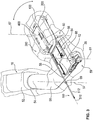
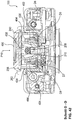
- Figure 3 shows a perspective view of a section of the manipulator arm 16 with a coupling unit 100 for coupling the manipulator arm 16 to the instrument unit 300 comprising a sterile unit 400.
- the coupling unit 100 is connected to a sterile lock 200 integrated into the sterile sleeve 38.
- the sterile lock 200 can be coupled and separated again both with the coupling unit 100 and with the sterile unit 400.
- the sterile lock 200 is shown coupled both to the coupling unit 100 and to the sterile unit 400.
- the coupling unit 100 is arranged at the distal end of the telescope arrangement 60.
- the telescope arrangement 60 has sections 62, 64, 66 which can be displaced relative to one another and is shown in FIG Figure 3 shown in an extended state.
- the sections 62, 64, 66 of the telescopic arrangement 60 can be retracted and extended with the aid of a drive unit 68, so that a surgical instrument 500 of the instrument unit 300 moves along the longitudinal axis 510 of the instrument shaft 512 together with the coupling unit 100, the sterile lock 200 and the sterile unit 400 will can.
- the segment 54 With the aid of a drive unit integrated in the segment 52, the segment 54 can be rotated about the axis of rotation 57 together with the segment 56 designed as an articulated arm.
- the segment 58 is connected to the segment 56 via a coupling gear 59, so that the segment 58 can be pivoted about the axis of rotation 61 after activation of a drive unit connected to the coupling gear 59.
- the coupling unit 100 is via an in Figure 3 Coupling gear, which is not visible, is arranged to be rotatable about the axis of rotation 67 relative to the segment 66.
- This coupling gear can also be driven via a drive unit connected to this coupling gear, so that when this drive unit is activated, the coupling unit 100 is rotated about the axis of rotation 67.
- the drive units of the coupling gears are controlled in such a way that the longitudinal axis 510 of the instrument shaft 512 when the manipulator arm 16 and its segments are moved around a pivot point 69 that is fixed in space and through which the longitudinal axis 510 of the during an operation, preferably by a trocar
- the instrument shaft 512 inserted into a patient is then rotated about the pivot point 69, so that it is ensured that the movement of the instrument 500 causes only little stress on the patient at the entry point of the instrument 500 in the patient, and in particular an injury to the patient the entry point of the instrument shaft 512 is prevented.
- FIG. 3 is a further perspective view of the arrangement according to FIG Figure 3 shown, the sections 62, 64, 66 of the telescopic assembly 60 in contrast to Figure 3 are shown in a retracted state, as a result of which the instrument unit 300 has been displaced in the direction of the longitudinal axis 510 of the instrument shaft 512 towards the proximal end of the surgical instrument 500.
- the instrument unit 300 is in the direction of the proximal end of the instrument 500 along the longitudinal axis 510 of the instrument 500 moved.
- the position of pivot point 69 has remained unchanged.
- the pivot point 69 is left unchanged in its spatial position by a corresponding control of the drive units of the coupling gears 59, in which a corresponding rotation of the segment 60 about the axis of rotation 61 and the Coupling unit 100 takes place around the axis of rotation 67. Furthermore, a virtual axis of rotation (not shown) generated by a corresponding drive of the coupling gear, which runs parallel to the axes of rotation 61, 67 and orthogonally to the axis of rotation 57, runs through the pivot point 69.
- the axis of rotation 57 of the segment 56 embodied as an articulated arm and the longitudinal axis 510 of the instrument 500 intersect at the pivot point 69.
- the pivot point 69 is also referred to as the pivot point.
- Figure 5 shows the coupling unit 100, the sterile lock 200 and the instrument unit 300 with the sterile unit 400 and the surgical instrument 500, which has an end effector 514, before the sterile lock 200 is joined to the coupling unit 100 and before the sterile unit 400 is subsequently joined to the sterile lock 200
- the flexible sterile sheath 38 designed as a sterile film is firmly connected to a peripheral connecting edge 202 of the sterile lock 200 via a suitable connection, such as a clamp, adhesive and / or welded connection, so that the sterile film 38 together with the sterile lock 200 forms a closed sterile cover around the non-sterile elements 16, 100 to be shielded by the sterile area 39, as is also the case in FIGS Figures 1 , 3 and 4th is shown.
- a suitable connection such as a clamp, adhesive and / or welded connection
- the sterile lock 200 is arranged between the sterile unit 400 and the coupling unit 100 and, when the sterile unit 400 is coupled to the coupling unit 100, enables a first transmission means 102 of the coupling unit 100 and a second transmission means of the sterile unit to be coupled directly 400.
- the second transmission medium is in Figure 15 denoted by the reference numeral 406.
- both mechanical energy and electrical energy are transmitted between the coupling unit 100 and the sterile unit 400 in the present exemplary embodiment.
- the first transmission means 102 of the coupling unit 100 has at least four mechanical drive elements 110 to 116 and the second transmission means 406 of the sterile unit 400 has four to the drive elements 110 to 116 in FIG Figure 15 Complementary driven elements 412 to 418 shown.
- the first transmission means 102 has an electrical transmission element 104 with two electrical contacts 106, 108 and the second transmission means 406 has an electrical transmission element complementary to the electrical transmission element 104 of the first transmission means 102.
- the complementary electrical transmission element comprises two in Figure 15 illustrated electrical contacts 422, 423.
- the first and second transmission means can also comprise more or fewer drive elements, driven elements and electrical transmission elements that transmit mechanical and / or electrical energy by direct coupling.
- a direct coupling is a coupling of the transmission means in which there are no further transmission elements between the first transmission means and the second transmission means for a transmission of mechanical and / or electrical energy and / or optical beams are provided, wherein in particular no electrical, mechanical or optical transmission elements are provided in a sterile barrier arranged between the coupling unit 100 and the sterile unit 400, such as the sterile lock 200.
- the coupling unit 100 also has an RFID read and write unit 121, with the aid of which an RFID transponder 494 of the sterile unit 400 can be read and / or written.
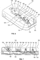
- FIG. 6 shows a schematic perspective view of the coupling unit 100 of the manipulator arm 16.
- the first transmission means 102 of the coupling unit 100 has an electrical transmission element 104 with two electrical contacts 106, 108, an optical transmission means 109 for transmitting light and / or optical signals, a first translational drive element 110 and a second translational drive element 112, each for transmitting a translational movement, and a first rotational drive element 114 and a second rotational drive element 116 for transmitting a rotational movement.
- the first and the second translational drive element 110, 112 are each designed as a linear lifting fork and the first and the second rotary drive element 114, 116 are designed as a drive pinion with teeth on the face.
- the coupling unit 100 has a first coupling sensor 118 arranged in a recess, which detects a first detection element formed by a first detection pin protruding from the sterile unit 400 when the sterile lock 200 is correctly coupled to the coupling unit 100 and the sterile unit 400 is correctly coupled to the sterile lock 200 .
- a first detection pin of the sterile unit 400 protrudes into the recess in which the first coupling sensor 118 is arranged, so that it detects the presence of the first detection pin serving as the first detection element.
- the first detection pin is in Figure 15 and denoted there by the reference numeral 426.
- the coupling unit 100 has a second coupling sensor 120 which is arranged laterally next to the drive elements 112, 114 in a further recess, as shown in FIG Figure 5 can be seen more clearly.
- the second coupling sensor 120 detects a second detection element formed by a second detection pin of the sterile unit 400 if both the coupling unit 100 are correctly coupled to the sterile lock 200 and the sterile lock 200 is correctly coupled to the sterile unit 400.
- the second detection pin is in Figure 11 and denoted there by the reference numeral 428.
- the coupling unit 100 has opposite guide grooves 122, 124 into which guide pins 204, 206 of the sterile lock 200 are inserted until they have reached the front end 123, 125 of the respective guide groove 122, 124, such as this in Figure 10 is shown.
- the guide pins 204, 206 protrude outward at a first end of the sterile lock 200 on opposite sides, as shown in FIG Figures 5 and 10 you can see.
- the opposite, second end of the sterile lock 200 is then pressed down so that the sterile lock 200 is rotated about an axis of rotation running through the guide pins 204, 206 until a locking lug 126 of a locking element 128 engages in a complementary locking area of the sterile lock 200.
- Figure 7 shows a longitudinal section through the coupling unit 100.
- the unlocking button 128 is arranged to be pivotable about an axis of rotation 130 and is held by a spring 132 in its Figure 7 shown locking position held.
- a finger is pressed onto an unlocking button 134 of the latching element 128, so that a spring 132 is tensioned and the latching element 128 is rotated together with the latching lug 126 in the direction of the arrow P0, so that the latching lug 126 is brought out of engagement with the complementary locking element of the sterile lock 200.
- the second end of the sterile lock 200 that was previously in engagement with the latching lug 126 can be pivoted out of the coupling unit 100.
- the sterile lock 200 can be completely separated from the coupling unit 100 by moving the sterile lock 200 with the guide pins 204, 206 in engagement with the guide grooves 122, 124 along the guide grooves 122 , 124 is pulled out of this until the guide elements 204, 206 are no longer in engagement with the guide grooves 122, 124.
- a receiving area formed by a corresponding recess in the housing of the coupling unit 100, which in the present exemplary embodiment at least partially surrounds the sterile lock 200 on three sides and on the bottom.
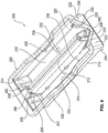
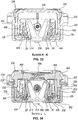
- FIG. 11 shows a perspective view of the sterile lock 200 with the lock flaps 208, 210 closed.
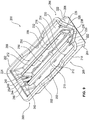
- Figure 9 shows a perspective view of the sterile lock 200 with the lock flaps 208, 210 open.
- the sterile lock 200 has a base 212 in which two openings 214, 216 that can be covered with the aid of the lock flaps 208, 210 are provided.
- the lock flaps 208, 210 are pivotably connected to the floor 212 via hinges. With the help of these hinges, the lock flaps 208, 210 of the in Figure 8 closed state shown in FIG Figure 9 shown open state pivotable. In the open state of the lock flaps 208, 210, the first transmission means 102 of the coupling unit 100 can be directly coupled to the second transmission means of the sterile unit 400.
- the sterile lock 200 also has two side walls 218, 220, a front end wall 222 and a rear end wall 224. On the outer sides of the side walls 218, 220 and the end walls 222, 224, the circumferential edge 202 is formed, with which, as already in connection with Figure 5 described, the sterile film of the sterile cover 38 is connected in a suitable manner.
- two guide and unlocking webs 228, 230 are fixedly arranged laterally next to a V-shaped recess 226 of the end wall 222, which when the sterile lock 200 is connected to the sterile unit 400 as unlocking elements for unlocking sterile flaps of the sterile unit 400 are used, as will be described in detail below.
- a first detection window 232 and a second detection window 234, each in the form of a through hole, are present in the floor 212 of the sterile lock 200, through which the aforementioned detection elements 426, 428 of the sterile unit 400 are passed so that they can be detected by the first coupling sensor 118 and the second coupling sensor 120 the coupling unit 100 can be detected.
- a guide bead 236 to 242 is provided at the front and rear ends of the sluice flaps 208, 210.
- the front guide beads 236, 238 are without function.
- the prongs 246, 248 of a guide fork 244 engage in the rear guide beads 240, 242.
- the guide fork 244 is secured in its upper in Figure 8 Depressed position shown and closes by the engagement of their prongs 246, 248 in the guide beads 240, 242 the lock flaps 208, 210 and holds them in their closed position.
- the lock flaps 208, 210 cannot be pushed apart by the engagement of the fork prongs 246, 248, so that the non-sterile transmission medium 102 of the coupling unit 100 is securely covered when the lock flaps 208, 210 are closed and the non-sterile elements of the coupling unit 100 are securely covered by the sterile area 39 are shielded.
- the lock flaps 208, 210 are structurally identical, so that a guide bead 236 to 242 is provided on each of the two end faces of the lock flaps 208, 210 for use on both sides.
- the lock flaps 208, 210 can also be designed differently and have a guide bead 240, 242 only on one side, into which the prongs 246, 248 of the guide fork 244 engage.
- a locking bead 250, 252 is provided in each of the side walls 218, 220, into which a locking element of the sterile unit 400 engages when the sterile lock 200 is connected to the sterile unit 400.
- a guide web 254 is provided which, when the sterile lock 200 is connected to the sterile unit 400, engages in a guide groove 452 of the sterile unit 400, as shown in FIG Figure 16 is shown.
- Figure 10 shows a partially sectioned side view of the sterile lock 200.
- a locking lug 255 is formed, into which the locking lug 126 of the locking element 128 of the coupling unit 100 engages when the coupling unit 100 is connected to the sterile lock 200.
- two positioning elements 256, 257 protruding from the bottom are provided, which engage in corresponding openings 136, 138 in the bottom of the receiving area of the coupling unit 100.
- the positioning elements 256, 257 are chamfered or alternatively conical so that they can easily be inserted into the in Figure 7 openings 136, 138 shown in the coupling unit 100 can be introduced.
- the detection windows 232 and 234 are each covered with a film 262, 264 which sterile shields the detection elements 426, 428 of the sterile unit 400 even when they pass through the detection windows 232, 234 into the depressions of the sensors 118, 120 of the coupling unit 100 protrude.
- the film 262, 264 is elastically and / or plastically deformed and does not tear.
- FIG. 11 shows a sectional view of the sterile lock 200 according to FIG Figure 10 along the section line AA.
- the axis of rotation about which the sluice flap 110 is pivoted from the closed to the open state and vice versa are denoted by D1 and the axis of rotation about which the sluice flap 208 is pivoted is denoted by D2.
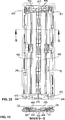
- Figure 12 shows a sectional view of the sterile lock 200 according to FIG Figure 10 along the section line BB and Figure 13 a sectional view of the sterile lock 200 according to Figure 10 along the section line CC.
- the side walls 218, 220, the end walls 222, 224 and the base 218 form a housing trough into which the sterile unit 400 can at least partially be inserted for connecting the sterile unit 400 to the coupling unit 100.
- the housing trough thus generally serves as the first connection area 266 of the sterile lock 200.
- the outside of the sterile lock 200 serves as a second connection area 268, with which the sterile lock 200 can be connected to the coupling unit 100.
- the front ends of the prongs 246, 248 of the guide fork 244 engage in the guide beads 240, 242.
- the facing side walls of the guide beads 240, 242 together with the front ends of the prongs 246, 248 of the guide fork 244 form a link guide through which the lock flaps 208, 210 are closed when the front ends of the prongs 246, 248 of the fork 244 upwards be swiveled.
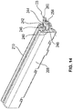
- Figure 14 shows a detailed view with partially open lock flaps 208, 210 and the prongs 246, 248 of the guide fork 244 engaging with the guide beads 240, 242 formed axis of rotation D3 in the in the Figures 8 to 14
- the lying representation of the sterile lock 200 shown in the figure is pivoted upwards, so that the lock flaps 208, 210 are closed with the aid of the spring force of the guide fork spring 258 and are held in a closed position.
- the guide pin 260 is used to guide and support the spring 258 and to support the guide fork 244.
- the guide fork 244 is then pivoted downward against the spring force of the guide fork spring 258, so that the sterile flaps 208, 210 through engaging elements provided on the sterile unit 400 are pivoted from the closed state to the open state.
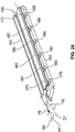
- Figure 15 shows a perspective view of the instrument unit 300 with the sterile unit 400 and the surgical instrument 500.
- the angled and rotatable end effector 5124 with actuatable gripping arms 516, 518 is arranged at the proximal end of the rotatable outer instrument shaft 512.
- the movements of the end effector 514 can be carried out with the aid of the drive elements 110 to 116 of the coupling unit 100 and the driven elements 408 to 414 of the sterile unit 400 when the sterile unit 400 is connected to the coupling unit 100 via the sterile lock 200.
- the sterile unit 400 has sterile flaps 402, 404, which are shown in FIG Figure 15 in an open and in Figure 16 are shown in a closed state.
- the second transmission means which is visible when the sterile flaps 402, 404 are open and is denoted by the reference number 406, is arranged in the interior of the sterile unit 400.
- the second transmission means 406 comprises one when coupled to the Coupling unit with the first translational drive element 110 in engagement first translational driven element 408 and with the second translational drive element 112 of the coupling unit 100 in engagement second translational driven element 410 each for transmitting a translation.
- a first rotary driven element 412 that can be coupled to the first rotary drive element 114 of the coupling unit 100 and a second rotary driven element 414 engaging with the second rotary drive element 116 of the coupling unit 100 are each provided for transmitting a rotational movement.
- the end effector 514 is pivoted about the tilt axis D4 in the direction of arrow P1 by up to 90 ° when the second translational driven element 410 of the sterile unit 400 is moved by the second translational drive element 112 of the coupling unit 100 in the direction of the Arrow P2 is moved.
- the gripping arms 516, 518 of the end effector 514 are moved apart and moved towards one another in opposite directions.
- the end effector 514 can be rotated independently of the instrument shaft 512.
- the instrument shaft 512 when coupled and driven with the second rotational drive element 116 of the coupling unit 100, the instrument shaft 512 can be rotated around its longitudinal axis 510, around the position of the tilt axis D4 of the end effector 514 around the axis of rotation 510 of the outer instrument shaft 512 to rotate without the end effector 514 itself being rotated.
- a first spring 416 is provided, which moves the first translational driven element 408 of the sterile unit 400 against the direction of the arrow P3 End position presses.
- a second spring 418 is provided which presses the second translationally driven element 410 of the sterile unit 400 against the direction of the arrow of the arrow P2 into its end position.
- the sterile unit 400 has a bearing 420 for the rotatable mounting of the outer instrument shaft 512 in the sterile unit 400.
- the surgical instrument 500 As an alternative to the surgical instrument 500, other instruments, such as scissors, needle holders, optical instruments, rinsing units, suction units, instruments of the Coupling high-frequency surgery and other instruments used in operations, in particular in laparoscopic operations, the second transmission means 406 being designed to implement the corresponding functions.
- instruments such as scissors, needle holders, optical instruments, rinsing units, suction units, instruments of the Coupling high-frequency surgery and other instruments used in operations, in particular in laparoscopic operations, the second transmission means 406 being designed to implement the corresponding functions.
- the second transmission means 406 further comprises an electrical transmission element with a first electrical contact 422 designed as a slip ring and a second electrical contact 423 designed as a slip ring, which when the sterile unit 400 is coupled to the coupling unit 100 via the sterile lock 200 with the electrical contacts 106, 108 of the coupling unit 100 establish an electrical connection for the transmission of high-frequency electrical energy for high-frequency surgery.
- no electrical transmission means can be provided either.
- the sterile unit 400 has two protruding cams 415, 417 which, when the sterile unit 400 is inserted into the sterile lock 200 in the unlocked sterile flaps 208, 210, press at least so far apart that the cams 415, 417 are arranged between the sterile flaps 208, 210.
- wedge-shaped engagement elements 456 to 462 of the sterile unit 400 press the sterile flaps 208, 210 further apart until they are in their Figure 9 open position shown are arranged.
- the bottom plate 401 of the sterile unit 400 points upwards and has two detection elements 426, 428 designed as protruding detection pins the first detection window 232 of the sterile lock 200 into the recess of the first coupling sensor 118 of the coupling unit 100 and the second detection element 428 protrudes through the second detection window 234 into the recess of the second coupling sensor 120 of the coupling unit 100
- Coupling sensors 118, 120 a correct coupling of the sterile lock 200 with the coupling unit 100 and the sterile unit 400 with the sterile lock 200 can be detected, so that only after a detection of the detection elements 426, 428 with the help of the coupling sensors 118, 120 a drive of the transmission transmission elements 110 to 116 is released by a control unit.
- the transmission of high-frequency energy is only released after the correct detection of the detection elements 426, 428 with the aid of the coupling sensors 118, 120 via the transmission elements 106, 108.
- the sterile unit 400 also has two latching elements 434, 436 arranged on opposite side walls 430, 432, which can be actuated with the aid of an actuating element 438, 440 protruding from the side wall 430, 432.
- the locking elements 434, 436 engage in the locking beads 250, 252 provided in the side walls 218, 220 of the sterile lock 200 when the sterile unit 400 is correctly connected to the sterile lock 200.
- the front end wall 442 of the sterile unit 400 has two grooves 444, 446 into which the guide and unlocking webs 228, 230 of the sterile lock 200 are inserted when the sterile unit 400 is connected to the sterile lock 200 and As will be explained in more detail below, unlock the sterile flaps 402, 404.
- the guide web 254 of the sterile lock 200 engages in the guide groove 452 present on the rear face 450 of the sterile unit 400.
- an actuating web 454 protrudes outward from the base plate 401, which pushes the guide fork 244 down when the sterile unit 400 is inserted into the sterile lock 200 and thereby releases the lock of the lock flaps 208, 210 by the guide fork 244.
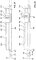
- FIG. 11 shows a side view of the sterile unit 400 with part of the instrument shaft 512 of the surgical instrument 500.
- Figure 18 shows a section of the sterile unit Figure 17 along the section line EE.
- the sterile flap 402 is in engagement with a guide flap 464 present in the sterile unit 400.
- the sterile flap 404 is in engagement with a guide flap 464 arranged in the interior of the sterile unit 400.
- To open the sterile flap 402 it is arranged to be pivotable about the axis of rotation D5 and the guide flap 464 is arranged to be pivotable about the axis of rotation D6.
- the sterile flap 404 To open the sterile flap 404, it is arranged to be pivotable about the axis of rotation D7 and the guide flap 464 is arranged to be pivotable about the axis of rotation D8.
- the sterile flaps 402, 404 are locked with the aid of the guide flaps 464, 466 and unlocked to open the sterile flaps 402, 404, as follows in connection with FIG Figures 22 to 28 will be explained in more detail.
- FIG. 4 is a section of the sterile unit 400 according to FIG Figure 17 shown along the section line FF.
- a spring 468 can be seen, with the aid of which the actuating elements 438, 440 and with them the latching lugs 434, 436 are pressed outwards so that the latching lugs 434, 436 into the locking beads 250, 252 of the sterile lock 200 be pressed when the sterile unit 400 has been correctly inserted into the sterile lock 200.
- Figure 20 shows a detail of a view of the instrument unit 300 from below with closed sterile flaps 402, 404 of the sterile unit 400.
- an unlocking pin 470 of the guide flap 464 and an unlocking pin 472 of the guide flap 466 are visible.
- the unlocking pin 470 protrudes into the guide and unlocking groove 444 and the unlocking pin 472 protrudes into the unlocking and guide groove 446.
- the guide and unlocking webs 228, 230 of the sterile lock 200 are inserted into the guide grooves 444, 446 and press the release pins 470, 472 starting from the in Figure 20 locked position shown in Figure 21 unlocked position shown.
- the sterile flaps 202, 204 and the guide flaps 464, 466 are shown unlocked and open.
- Figure 22 shows a top view of the sterile flap system of the sterile unit 400 with closed sterile flaps 402, 404 and closed and locked guide flaps 464, 466.
- the sterile flap system has a spring 474 which is pretensioned and the guide flap 466 and the sterile flap 404 engaged with the guide flap 466 in the in FIG Figure 22 shown closed state. After the guide flap 466 has been unlocked, the guide flap 466 and the sterile flap 404 can be opened against the spring force of the spring 474.
- the sterile flap system also has a spring 476 which is preloaded and holds the guide flap 464 and the sterile flap 402 in their closed state.
- FIG. 13 is a sectional view of the sterile valve system according to FIG Figure 22 along the section line GG with closed guide flaps 464, 466 and closed sterile flaps 402, 404.
- FIG. 13 is a sectional view of the sterile valve system according to FIG Figure 24 along the section line HH with open guide flaps 464, 466 and open sterile flaps 402, 404.
- Figure 26 shows a perspective detailed view of the sterile flap 404 and the sterile flap 404 engaged therewith in a closed, locked position.
- the spring 474 (not shown) pushes the guide flap 466 against the arrow P5 into its locked position and the spring 474 additionally presses the guide flap 466 against the direction of the arrow P4 into its locked position, so that the unlocking pins 470, 472 are moved against the spring force of the springs 474, 476 in the direction of the arrows P4, P5.
- the sterile flap 404 On the side facing the guide flap 466, the sterile flap 404 has seven guide and locking grooves 478 to 488, in each of which a guide and locking web 479 to 489 of the guide flap 466 engages.
- the guide and locking webs 479 to 489 are arranged on the side of the guide flap 466 facing the sterile flap 404.
- the sterile flap 404 and the guide flap 466 are in Figure 26 shown in their locked position. In this locked state, the guide and locking webs 479 to 489 are each arranged behind a projection of the guide and locking grooves 478 to 488, so that a rotation of the sterile flap 404 and the guide flap 466 about the axes of rotation D5, D6 in the direction of the arrows P6 and P7 is prevented.
- the sterile flap arrangement of the sterile flap 402 and the guide flap 464 are mirror-symmetrical to the one in FIG Figure 26
- Figure 27 shows a plan view of the guide flap 466 and the sluice flap 404 in a partially sectioned illustration in the closed and locked state.
- the guide and locking groove 480 of the guide flap 466 is visible in the cut area.
- the guide and locking groove 480 is arranged behind a projection 490 of the guide and locking groove 480, which serves as a locking lug, so that when a moment acts on the guide flap 466 and / or on the sterile flap 404 for a rotary movement of the guide flap 466 in the direction of the arrow P7 or the sterile flap 404 in the direction of arrow P6, the guide and locking element 480 would be pressed against the locking lug 490.
- the guide flap 466 By moving the guide flap 466 in the direction of arrow P5, the guide flap 466 has been moved relative to the sterile flap 404, so that the guide and locking web 481 is no longer arranged behind the projection 490, but in the area of the outwardly open guide groove 480.
- the sterile flap 404 can be rotated in the direction of the arrow P6 and the guide flap 466 in the direction of the arrow P7, so that the sterile flap 404 and the guide flap 466 can each be moved into their open position.
- the further guide and locking webs 479 to 489 are moved together with the guide and locking web 481 out of the blocking area of the respective guide and locking groove 478 to 488 formed by the projection, as is the case for the guide and locking web 481 and the guide and locking webs Locking groove 480 has been explained.
- Figure 30 shows a partially sectioned illustration of an arrangement with a sterile lock 200 and a sterile unit 400 connected to the sterile lock 200.
- Figure 31 shows a sectional view of the arrangement according to FIG Figure 30 along the section line II
- Figure 32 a sectional view of the arrangement according to Figure 30 along the section line JJ
- Figure 33 a sectional view of the arrangement according to Figure 30 along the section line KK
- Figure 34 a sectional view of the arrangement according to Figure 30 along the section line LL.
- the sterile unit 400 has an RFID transponder 494 in which preferably at least one unique identifier of the sterile unit 400 and preferably information about the surgical instrument 500 coupled to the sterile unit 400 is stored.
- further information such as manufacturer information of the sterile unit 400, batch information, shelf life information, can be stored, preferably in an area of the RFID transponder 494 that cannot be overwritten.
- Information about the first use of the sterile unit 400, in particular the time of first use and / or an unambiguous operation identifier of the operation during which the first use of the sterile unit 400 took place, can be stored in a memory area of the RFID transponder 494 that can preferably only be written once, so that this information makes it possible to rule out the possibility of the sterile unit 400 being used in a further operation, in particular in a further patient.
- the identifier of the RFID transponder 494 and / or the information stored in the RFID transponder 494 can be read with the aid of the RFID read and write unit 121 of the coupling unit 100 and, if necessary, information can be stored in the form of data in the RFID transponder 494.
- Figure 32 shows that when the sterile unit 400 is connected to the sterile lock 200, both the lock flaps 208, 210 and the guide flaps 464, 466 and the sterile flaps 402, 404 are open, so that the second transmission medium 406 of the sterile unit 400 through the flaps 208, 210 , 402, 404, 464, 466 through it can be brought into direct contact with the first transmission means 102.
- both a direct electrical connection between the electrical contact elements 106, 108 of the coupling unit 100 and the electrical contact elements 422, 423 of the sterile unit 400 and a direct engagement of the mechanical transmission elements 110 to 116 of the coupling unit can be established 100 take place with the transmission elements 408 to 414 of the sterile unit 400.
- the sterile outside of the sterile flap 402 is arranged opposite the sterile outside of the lock flap 208.
- the sterile outside of the sterile flap 404 is arranged opposite the sterile outside of the sluice flap 210, so that even if the sterile flap 402 comes into direct contact with the sluice flap 208 or if the sterile flap 404 comes into direct contact with the sluice flap 210, there is no contamination of the Lock flaps 208, 210 contamination of the sterile flaps 402, 404 takes place.
- Figure 34 it is shown how the locking elements 434, 436 of the sterile unit 400 engage in the locking beads 250, 252 of the sterile lock 200 when the sterile unit 400 is correctly connected to the sterile lock 200. Furthermore, in Figure 34 to see how the detection element 426 protrudes through the first detection window 232, the detection element 426 protruding into the recess of the first sensor 118 of the coupling unit 100 when the sterile lock 200 is connected to the coupling unit 100, so that it detects the detection element 426. Furthermore, in Figure 34 the film 162 is shown, which is elastically and / or plastically deformed by the detection element 426 and thereby covers the detection element 426 in a sterile manner.
- Figure 35 shows elements of the sterile flap system with the sterile flaps 402, 404 and the guide flaps 464, 466 and elements of the sluice flap system of the sterile sluice 200 with the sluice flaps 208, 210.
- the prongs 246, 248 of the guide fork 244 engage in the guide beads 240, 242 in the closed state of the lock flaps 208, 210, so that a form-fitting connection is present via this engagement, which prevents the lock flaps 208, 210 from being pushed open.
- Both the lock flaps 208, 210 and the guide flaps 464, 466 and the sterile flaps 402, 404 are extended into the Figures 33, 34 shown Position open.
- the locking pin 470 is shown in FIG Figure 35 shown in its locked position and the release pin 472 in its unlocked position.
- the guide flap 464 and the sterile flap 402 in spite of the arrangement of the unlocking pin 470 in the locked position, about their axes of rotation D5, D6 up to the position shown in FIG Figure 35 shown partially open position have been pivoted, although this would not be possible with an actual locking.
- FIG. 3 is a side view of the arrangement according to FIG Figures 30 to 35 shown and in Figure 37 a sectional view of a portion of the arrangement according to Figure 36 along the cutting line MM.
- Figure 38 Figure 3 is a cross-sectional view of the arrangement of FIG Figure 36 shown along the section line NN.
- Figure 39 shows a plan view of an arrangement with the coupling unit 100, the sterile lock 200 and the instrument unit 300, which comprises the sterile sterile unit 400 and the sterile surgical instrument 500.
- Figure 40 shows a sectional view of the arrangement according to FIG Figure 39 along the cutting line OO in a first position immediately before connecting the sterile unit 400 of the instrument unit 300 to the sterile lock 200 already coupled to the coupling unit 100.
- Figure 41 shows a sectional view of the arrangement according to FIG Figure 39 along the cutting line OO in a second position when the sterile unit 400 of the instrument unit 300 is connected to the sterile lock 200 already coupled to the coupling unit 100.
- Figure 42 shows a sectional view of the arrangement according to FIG Figure 39 along the section line OO in a third position in which the sterile unit 400 of the instrument unit 300 is connected to the sterile lock 200 coupled to the coupling unit 100, so that the first transmission means 102 of the coupling unit 100 for direct coupling with the transmission elements of the second transmission means 406 are in engagement.
- the guide flaps 464, 466 are moved by the introduction of the guide and unlocking webs 228, 230 into the grooves 444, 446 and thereby already along their axis of rotation D6, D8 in the direction of the arrows P4, P5 from their locked position to their unlocked position has been moved so that the sterile flaps 402, 404 together with the guide flaps 464, 466 have been pushed open by a movement of the sterile unit 400 in the direction of arrow P10 and the resulting contact of the sterile flaps 402, 404 with the sluice flaps 208, 210.
- the sterile unit 400 gets deeper into the receiving area of the sterile lock 200 provided for receiving the sterile unit 400, so that the actuating web 454 engages with the guide fork 244 and pivots it against the spring force of the guide fork spring 258.
- the prongs 246, 248 of the guide fork 244 are in engagement with the guide beads 240, 242 so that the lock flaps 208, 210 can be pressed apart by the cams 415, 417 and thereby opened.
- the interlocking of the fork prongs 246, 248 with the guide beads 240, 244 generated in this way securely holds the lock flaps 208, 210 in their closed position so that the lock flaps 208, 210 cannot be opened from the outside. Also, when the sterile unit 400 is removed from the sterile lock 200, the guide flaps 464, 466 are completely closed with the aid of the springs 474, 476 and moved into their locked position, so that the sterile flaps 402, 404 cannot be opened afterwards even if there is an external force on the sterile flaps 402, 404 .
- Figure 43 shows a section of an instrument unit 1300 with a sterile unit 1400 and a surgical instrument 1500 according to a second embodiment.
- the sterile unit 1400 of the instrument unit 1300 does not have sterile flaps but rather a blind 1410 for sterile covering of the driven elements.
- the further construction and the function of the instrument unit 1300 corresponds to the construction and the function of the instrument unit 300 according to FIGS Figures 1 to 42 match.
- Figure 44 shows a section of a sterile cover 1038 with a sterile lock 1200 which, in contrast to the sterile lock 200, has no sterile flaps but a louvre 1210 for sterile shielding of drive elements of the coupling unit 100.
- the louvre 1410 of the coupling unit 1400 and the louvre 1210 of the sterile lock 1200 are suitably activated by mechanical intervention when connecting the sterile unit 1400 with the sterile lock 1200 or the sterile unit 1400 with the sterile lock 200 or the sterile unit 400 with the sterile lock 1200 open.
- active drive elements such as an electric motor in each case, can be provided for opening or closing the respective blinds 1410, 1210.
- FIG 45 a section of an instrument unit 2300 with a sterile unit 2400 according to a third embodiment is shown.
- the sterile unit 2400 has no elements for sterile covering of the driven elements, so that this instrument unit 2400 after separation from the sterile lock 200, 1200 or after separation from another in Figure 46 Sterile lock 2200 shown is removed from the sterile area 39 immediately.
- the sterile cover 2038 shown comprises a sterile lock 2200, which can be connected to the coupling unit 100 in the same way as the sterile unit 200.
- the sterile lock 2200 does not have any lock flaps but rather comprises a foil provided with predetermined breaking points indicated by means of dotted lines, which is torn open at the predetermined breaking points when a sterile unit 400, 1400, 2400 is connected to the sterile lock 2200, so that a direct coupling of the drive elements 110 to 116 of the coupling unit 100 with the driven elements 408 to 414 is easily possible.
- the sterile unit 400, 1400, 2400 is preferably not separated during an operation, but rather only after the operation has ended.
Description
Die Erfindung betrifft eine Vorrichtung zur robotergestützten Chirurgie mit mindestens in einem nicht sterilen Bereich angeordneten Manipulatorarm mit einer Koppeleinheit, die mindestens ein erstes Übertragungsmittel hat. Die Vorrichtung hat mindestens eine in einem sterilen Bereich angeordnete Sterileinheit, die mindestens ein zweites Übertragungsmittel hat und eine sterile Abdeckung zum Abschirmen des Manipulatorarms von dem sterilen Bereich. Die Erfindung betrifft weiterhin eine Anordnung zur robotergestützten Chirurgie, die eine solche Vorrichtung zur robotergestützten Chirurgie und mindestens eine Eingabeeinrichtung zur Eingabe mindestens eines Eingabekommandos umfasst. Ferner betrifft die Erfindung eine Sterilschleuse, insbesondere zum Einsatz in einer solchen Vorrichtung, sowie ein Verfahren zur robotergestützten Chirurgie, bei dem eine Sterileinheit mehrmals nacheinander mit einem Manipulatorarm verbindbar ist.The invention relates to a device for robot-assisted surgery with a manipulator arm arranged in at least one non-sterile area with a coupling unit which has at least one first transmission means. The device has at least one sterile unit which is arranged in a sterile area and which has at least one second transmission means and a sterile cover for shielding the manipulator arm from the sterile area. The invention further relates to an arrangement for robot-assisted surgery which comprises such a device for robot-assisted surgery and at least one input device for inputting at least one input command. The invention also relates to a sterile lock, in particular for use in such a device, and to a method for robot-assisted surgery in which a sterile unit can be connected to a manipulator arm several times in succession.
In der minimal invasiven Chirurgie werden zunehmend sogenannte Telemanipulatorsysteme, die auch als Roboterassistenzsysteme bezeichnet werden, eingesetzt. Das sterile Operationsfeld wird vor den nicht sterilen Elementen des Telemanipulatorsystems mit Hilfe einer sterilen Abdeckung geschützt. Durch die sterile Abdeckung wird sowohl eine Kontamination des sterilen Operationsfeldes als auch einer Verschmutzung des Telemanipulatorsystems durch Körperflüssigkeiten und/oder Gewebe des operierten Patienten oder des Operationspersonals verhindert. Dadurch wird das Risiko von Kreuzkontaminationen verringert.So-called telemanipulator systems, which are also referred to as robot assistance systems, are increasingly being used in minimally invasive surgery. The sterile operating field is protected from the non-sterile elements of the telemanipulator system with the aid of a sterile cover. The sterile cover prevents both contamination of the sterile operating field and contamination of the telemanipulator system by body fluids and / or tissue of the operated patients or operating staff prevented. This reduces the risk of cross-contamination.
Mit Hilfe des Telemanipulatorsystems werden chirurgische Instrumente und/oder Endoskope aufgrund von Bedieneingaben in ihrer Lage und Orientierung gesteuert und kommen dabei zwangsläufig in Körperkontakt mit dem zu operierenden Patienten, sodass die chirurgischen Instrumente und/oder Endoskope mit Körperflüssigkeiten und/oder Gewebe des operierten Patienten verunreinigt werden. Gleichzeitig müssen die chirurgischen Instrumente mechanisch, elektrisch und/oder optisch an das Telemanipulatorsystem angekoppelt werden, um eine aktive Positionierung und Ausrichtung des chirurgischen Instruments sowie eine gewünschte Betätigung eines chirurgischen Instruments realisieren zu können. Hierzu haben die chirurgischen Instrumente, Endoskope oder zu bedienende medizinische Geräte eine Koppelschnittstelle, die als Koppeleinheit ausgebildet sein kann und auch als Sterileinheit bezeichnet wird.With the help of the telemanipulator system, surgical instruments and / or endoscopes are controlled in their position and orientation on the basis of operator inputs and in the process inevitably come into body contact with the patient to be operated on, so that the surgical instruments and / or endoscopes contaminate the body fluids and / or tissue of the operated patient will. At the same time, the surgical instruments must be coupled mechanically, electrically and / or optically to the telemanipulator system in order to be able to implement active positioning and alignment of the surgical instrument and a desired actuation of a surgical instrument. For this purpose, the surgical instruments, endoscopes or medical devices to be operated have a coupling interface which can be designed as a coupling unit and is also referred to as a sterile unit.
Das während eines chirurgischen Eingriffs genutzte Material einschließlich der verwendeten chirurgischen Apparate und Instrumente und die weiteren Bestandteile des Telemanipulatorsystems können in drei Kategorien eingeteilt werden:
- Kategorie 1: Das Material ist steril und wird während des chirurgischen Eingriffs kontaminiert. Das Material wird nach der Operation entsorgt. Es erfolgt somit eine Einmalverwendung des Materials.
- Kategorie 2: Das Material ist steril, wird während des chirurgischen Eingriffs kontaminiert und nach der Operation gereinigt und sterilisiert. Es erfolgt somit eine Mehrfachverwendung des Materials. Solche mehrfach verwendeten Materialien müssen entsprechend den Anforderungen an eine prozessfähige Sterilisierbarkeit konstruiert und produziert sein.
- Kategorie 3: Das Material ist nicht steril. Während des chirurgischen Eingriffs wird durch eine sterile Abdeckung und Umverpackung eine Kontamination des sterilen Operationsfeldes verhindert. Gleichzeitig wird das nicht sterile Material vor Kontakt mit Körperflüssigkeiten und/oder Gewebe geschützt.
- Category 1: The material is sterile and will be contaminated during the surgical procedure. The material will be disposed of after the operation. The material is therefore used once.
- Category 2: The material is sterile, contaminated during surgery and cleaned and sterilized after surgery. This means that the material is used multiple times. Such re-used materials must be designed and produced in accordance with the requirements for process-capable sterilizability.
- Category 3: The material is not sterile. During the surgical procedure, a sterile cover and outer packaging prevent contamination of the sterile operating field. At the same time, the non-sterile material is protected from contact with body fluids and / or tissue.
Ist es erforderlich, Geräte der Kategorie 1 oder der Kategorie 2 mit Geräten der Kategorie 3 zu koppeln, ist eine Sterilschnittstelle erforderlich, die eine Kontamination der Geräte der Kategorie 1 bzw. der Kategorie 2 durch die nicht sterilen Geräte der Kategorie 3 verhindert und umgekehrt eine Verunreinigung der Geräte der Kategorie 3 verhindert, da diese im allgemeinen als nicht sterilisierbare autoklavierbare Komponenten technisch ausgeführt sind. Die Ausführung von Geräten als sterilisierbare und autoklavierbare Komponenten erfordert eine besondere technische Auslegung des Geräts für den Sterilisationsprozess, sodass hierfür ein höherer Entwicklungsaufwand sowie ein erheblicher Validierungsaufwand zum Nachweis der Wirksamkeit des Sterilisationsprozesses erforderlich sind. Für einen solchen Nachweis ist es insbesondere erforderlich, das Gerät mehrfach nacheinander zu kontaminieren, zu sterilisieren, eine Wirksamkeitsprüfung der Sterilisation durchzuführen sowie eine Funktionsprüfung nach erfolgter Sterilisation durchzuführen. Dabei ist ein Nachweis zu erbringen, dass die Geräte nach jeder Sterilisation sicher sterilisiert und somit wieder verwendet werden könnten.If it is necessary to couple devices of
Aus dem Dokument
Somit wird mit Hilfe des Steriladapters verhindert, dass die Rotationsaktuatoren und die elektrischen Anschlüsse des sterilen chirurgischen Instruments direkt in Kontakt mit den Rotationsaktuatoren und den elektrischen Anschlüssen der Koppeleinheit des nicht sterilen Manipulatorarms kommen. Eine Kontamination des chirurgischen Instruments durch den Kontakt mit nicht sterilen Teilen des Manipulatorarms wird durch den Steriladapter verhindert. Bei dieser Lösung ist es jedoch erforderlich, dass der Steriladapter drehbar gelagerte Übertragungsmittel haben muss sowie Übertragungsmittel zur Übertragung von elektrischen Signalen, wodurch der Adapter aufwendig herzustellen und störanfällig ist. Insbesondere ist es aufwendig, die Drehbarkeit der Übertragungsmittel sicherzustellen, wenn die Übertragungsmittel in Kontakt mit Körperflüssigkeit kommen.The sterile adapter thus prevents the rotation actuators and the electrical connections of the sterile surgical instrument from coming into direct contact with the rotation actuators and the electrical connections of the coupling unit of the non-sterile manipulator arm. Contamination of the surgical instrument through contact with non-sterile parts of the manipulator arm is prevented by the sterile adapter. In this solution, however, it is necessary that the sterile adapter must have rotatably mounted transmission means and transmission means for transmitting electrical signals, whereby the adapter is expensive to manufacture and prone to failure. In particular, it is expensive to ensure the rotatability of the transmission means when the transmission means come into contact with body fluid.
Grundsätzlich ist jedes Element in der Funktionskette zur Kopplung des Manipulatorarms und des Instruments eine mögliche Fehlerquelle und ist mit zusätzlichen Kosten verbunden. Der Steriladapter selbst ist als Teil der Sterilfolie zur Einmalverwendung vorgesehen.
Aus dem Dokument
From the document
Aus dem Dokument
Aufgabe der vorliegenden Erfindung ist es, eine Vorrichtung und ein Verfahren zur robotergestützten Chirurgie anzugeben, bei denen eine sterile Kopplung eines in einem nicht sterilen Bereich angeordneten Manipulatorarms mit einer in einem sterilen Bereich angeordneten Sterileinheit einfach möglich ist. Ferner sind eine Anordnung zur robotergestützten Chirurgie innerhalb eines sterilen Bereichs sowie eine Sterilschleuse zum Koppeln einer Koppeleinheit eines Manipulatorarms mit einer Sterileinheit anzugeben.The object of the present invention is to provide a device and a method for robot-assisted surgery in which a simple sterile coupling of a manipulator arm arranged in a non-sterile area with a sterile unit arranged in a sterile area is possible. Furthermore, an arrangement for robot-assisted surgery within a sterile area and a sterile lock for coupling a coupling unit of a manipulator arm to a sterile unit are to be specified.
Diese Aufgabe wird durch eine Vorrichtung zur robotergestützten Chirurgie mit den Merkmalen des Anspruchs 1 sowie durch eine Anordnung, durch eine Sterilschleuse und durch ein Verfahren mit den Merkmalen des jeweiligen unabhängigen Anspruchs gelöst. Vorteilhafte Weiterbildungen der Erfindung sind in den abhängigen Ansprüchen angegeben.This object is achieved by a device for robot-assisted surgery with the features of
Bei der Erfindung wird insbesondere durch das Vorsehen einer Sterilschleuse, die sowohl mit einer Koppeleinheit als auch mit einer Sterileinheit verbindbar ist, beim Verbinden der Sterileinheit mit der Sterilschleuse die Schleusenklappe, vorzugsweise automatisch mechanisch, geöffnet, sodass das erste Übertragungsmittel der Koppeleinheit und das zweite Übertragungsmittel der Sterileinheit einander gegenüberliegend angeordnet sind, ohne dass ein weiteres Übertragungselement zwischen ihnen angeordnet ist. Dabei können sich die Übertragungsmittel direkt kontaktieren oder es erfolgt eine Übertragung über einen Luftspalt zwischen dem ersten Übertragungsmittel und dem zweiten Übertragungsmittel. Dadurch wird bei einer Verbindung der Sterileinheit mit der Sterilschleuse das durch die Schleusenklappe steril abgedeckte erste Übertragungsmittel für eine Übertragung mit dem zweiten Übertragungsmittel freigegeben. Beim Trennen der Sterileinheit von der Sterilschleuse wird zumindest das erste Übertragungsmittel und wieder steril abgeschirmt. Vorzugsweise ist die Sterilschleuse beim Verbinden und Trennen der Sterileinheit mit bzw. von der Sterilschleuse bereits mit der Koppeleinheit verbunden. Vorzugsweise bleibt die Sterilschleuse über den gesamtem Zeitraum des chirurgischen Eingriffs mit der Koppeleinheit verbunden, wobei die Sterileinheit mehrfach von der Koppeleinheit des Manipulatorarms getrennt und wieder mit diesen verbunden bzw. gegen eine weitere Sterileinheit ausgetauscht werden kann. Ferner ist es möglich, die Sterilschleuse mit der Koppeleinheit und der Sterileinheit derart zu verbinden, dass das erste Übertragungsmittel mit dem zweiten Übertragungsmittel in direkter Verbindung, vorzugsweise in direktem Eingriff, steht.In the invention, in particular by providing a sterile lock, which can be connected to both a coupling unit and a sterile unit, when the sterile unit is connected to the sterile lock, the lock flap is opened, preferably automatically mechanically, so that the first transmission means of the coupling unit and the second transmission means of the sterile unit are arranged opposite one another without a further transmission element being arranged between them. The transmission means can contact each other directly or a transmission takes place via an air gap between the first transmission means and the second transmission means. As a result, when the sterile unit is connected to the sterile lock, the first transfer means, which is covered in a sterile manner by the lock flap, is released for transfer to the second transfer means. When the sterile unit is separated from the sterile lock, at least the first transmission medium is shielded in a sterile manner. Preferably the sterile lock is already connected to the coupling unit when connecting and disconnecting the sterile unit with or from the sterile lock. The sterile lock preferably remains connected to the coupling unit over the entire period of the surgical intervention, the sterile unit being able to be separated several times from the coupling unit of the manipulator arm and reconnected to it or exchanged for a further sterile unit. It is also possible to connect the sterile lock with the coupling unit and the sterile unit in such a way that the first transmission means is in direct connection, preferably in direct engagement, with the second transmission means.
Durch die Erfindung ist es somit insbesondere möglich, die Sterilschleuse ohne mechanische und/oder elektrische Übertragungsmittel auszustatten, sodass sowohl eine sichere sterile Abschirmung des nicht sterilen Manipulatorarms und der nicht sterilen Koppeleinheit als auch eine sichere Kopplung des ersten Übertragungsmittels mit dem zweiten Übertragungsmittel ohne Zwischenschaltung von weiteren Übertragungsmitteln, insbesondere ohne Zwischenschaltung von weiteren mechanischen Übertragungsmitteln, möglich ist. Die sterile Abdeckung umfasst insbesondere ein steriles flexibles Material, wie eine Sterilfolie, und die mindestens eine Sterilschleuse.The invention makes it possible, in particular, to equip the sterile lock without mechanical and / or electrical transmission means, so that both secure sterile shielding of the non-sterile manipulator arm and the non-sterile coupling unit and secure coupling of the first transmission means with the second transmission means without the interposition of further transmission means, in particular without the interposition of further mechanical transmission means, is possible. The sterile cover in particular comprises a sterile flexible material, such as a sterile film, and the at least one sterile lock.
Es ist vorteilhaft, wenn die Sterileinheit mindestens eine Sterilklappe hat, die in einem geschlossenen Zustand das zweite Übertragungsmittel steril abschirmt. Beim Verbinden der Sterileinheit mit der Sterilschleuse erfolgt dann jeweils eine Bewegung der Schleusenklappe und der Sterilklappe vom geschlossenen Zustand in den geöffneten Zustand, sodass eine direkte Übertragung zwischen dem ersten Übertragungsmittel und dem zweiten Übertragungsmittel durch eine von der Schleusenklappe und der Sterilklappe im geöffneten Zustand freigegebene Öffnung möglich ist. Beim Trennen der Sterileinheit von der Sterilschleuse erfolgt eine Bewegung der Schleusenklappe und der Sterilklappe jeweils vom geöffneten Zustand in den geschlossenen Zustand, sodass die Schleusenklappe nach dem Trennen das erste Übertragungsmittel und die Sterilklappe nach dem Trennen das zweite Übertragungsmittel vom sterilen Bereich abschirmen.It is advantageous if the sterile unit has at least one sterile flap which, in a closed state, shields the second transmission medium in a sterile manner. When the sterile unit is connected to the sterile sluice, the sluice flap and the sterile flap each move from the closed state to the open state, so that a direct transmission between the first transmission means and the second transmission means through an opening released by the sluice flap and the sterile flap in the open state is possible. When the sterile unit is separated from the sterile lock, the lock flap and the sterile flap each move from the open state to the closed one State so that the lock flap shields the first transmission medium after separation and the sterile flap shields the second transmission medium from the sterile area after separation.
Vorzugsweise umfasst das erste Übertragungsmittel der Koppeleinheit mindestens ein Antriebselement und/oder mindestens eine erste elektrische Schnittstelle und/oder mindestens eine erste optische Schnittstelle. Das zweite Übertragungsmittel der Sterileinheit mindestens ein angetriebenes Element und/oder eine zweite elektrische Schnittstelle und/oder eine mindestens eine zweite optische Schnittstelle. Die Sterilschleuse ist mit der Koppeleinheit und der Sterileinheit derart verbindbar, dass das mindestens eine Antriebselement mit dem mindestens einen angetriebenen Element mechanisch direkt in Eingriff steht. Dadurch können zwischen der Koppeleinheit und der Sterileinheit einfach und sicher Momente übertragen werden. Ist die Sterileinheit Teil einer chirurgischen Instrumenteneinheit kann mit Hilfe der von der Koppeleinheit zur Sterileinheit übertragenen Momente das chirurgische Instrument der Instrumenteneinheit bewegt und/oder betätigt werden, indem mindestens ein Moment vom Antriebselement zum angetriebenen Element übertragen wird. Alternativ oder zusätzlich können die erste elektrische Schnittstelle mit der zweiten elektrischen Schnittstelle und/oder die erste optische Schnittstelle mit der zweiten optischen Schnittstelle gekoppelt werden.The first transmission means of the coupling unit preferably comprises at least one drive element and / or at least one first electrical interface and / or at least one first optical interface. The second transmission means of the sterile unit has at least one driven element and / or a second electrical interface and / or at least one second optical interface. The sterile lock can be connected to the coupling unit and the sterile unit in such a way that the at least one drive element is in direct mechanical engagement with the at least one driven element. This allows torques to be transmitted easily and reliably between the coupling unit and the sterile unit. If the sterile unit is part of a surgical instrument unit, the surgical instrument of the instrument unit can be moved and / or actuated with the aid of the torques transmitted from the coupling unit to the sterile unit, in that at least one torque is transmitted from the drive element to the driven element. Alternatively or additionally, the first electrical interface can be coupled to the second electrical interface and / or the first optical interface can be coupled to the second optical interface.
Die Sterileinheit ist gemäß der Definition der Beschreibungseinleitung Material der Kategorie 1 und 2 und ist somit steril.According to the definition in the introduction to the description, the sterile unit is material of
Ferner ist es vorteilhaft, wenn die Koppeleinheit mit einem ersten Verbindungsbereich der Sterilschleuse verbindbar ist und wenn die Sterileinheit mit einem zweiten Verbindungsbereich der Sterilschleuse verbindbar ist. Der erste Verbindungsbereich und der zweite Verbindungsbereich sind vorzugsweise auf voneinander abgewandten Seiten der Sterilschleuse angeordnet. Dadurch ist eine einfache Kopplung und somit eine einfache Handhabung sowohl der sterilen Abdeckung als auch der Sterileinheit vor, während und nach einem chirurgischen Eingriff möglich. Ferner ist es besonders vorteilhaft, wenn der zweite Verbindungsbereich als Aufnahmebereich ausgebildet ist, in dem die Sterileinheit beim Verbinden mit dem zweiten Verbindungsbereich zumindest teilweise aufnehmbar ist. Dadurch kann eine einfache und sichere Verbindung zwischen der Sterileinheit und der Sterilschleuse hergestellt werden. Insbesondere kann die Sterileinheit zumindest teilweise in den Aufnahmebereich hineingedrückt und dort verriegelt werden.It is also advantageous if the coupling unit can be connected to a first connection area of the sterile lock and if the sterile unit can be connected to a second connection area of the sterile lock. The first connection area and the second connection area are preferably facing away from each other Sides of the sterile lock arranged. This enables simple coupling and thus simple handling of both the sterile cover and the sterile unit before, during and after a surgical procedure. Furthermore, it is particularly advantageous if the second connection area is designed as a receiving area in which the sterile unit can be at least partially received when it is connected to the second connection area. This enables a simple and secure connection to be established between the sterile unit and the sterile lock. In particular, the sterile unit can be at least partially pressed into the receiving area and locked there.
Ferner ist es vorteilhaft, wenn die Sterilschleuse einen dritten Verbindungsbereich hat, mit dem die flexible Abdeckung verbindbar ist, wobei der dritte Verbindungsbereich vorzugsweise umlaufend um die Sterilschleuse, insbesondere an der Mantelfläche umlaufend, vorzugsweise zwischen dem ersten und zweiten Verbindungsbereich, angeordnet ist. Durch die Sterilschleuse erfolgt eine einfache Verbindung des sterilen Bereichs und des nicht sterilen Bereichs zur Kopplung der Koppeleinheit mit der Sterileinheit, ohne dass die Sterileinheit derart kontaminiert wird, dass sie nach einer Trennung von der Sterilschleuse nicht mehr im sterilen Bereich verbleiben kann.It is also advantageous if the sterile lock has a third connection area to which the flexible cover can be connected, the third connection area preferably being arranged circumferentially around the sterile lock, in particular on the circumferential surface, preferably between the first and second connection area. The sterile lock provides a simple connection between the sterile area and the non-sterile area for coupling the coupling unit to the sterile unit without the sterile unit being contaminated in such a way that it can no longer remain in the sterile area after being separated from the sterile lock.
Vorzugsweise ist die Koppeleinheit am proximalen Ende des Manipulatorarms angeordnet. Alternativ oder zusätzlich ist die Sterileinheit Bestandteil eines chirurgischen Instruments, eines Endoskops und/oder eines medizinischen Geräts, wobei die Sterileinheit insbesondere am distalen Ende des chirurgischen Instruments, des Endoskops und/oder des medizinischen Geräts angeordnet ist. Dadurch kann die Sterilschleuse für verschiedene bei einer Operation eines Patienten benötigten Instrumente und Geräte genutzt werden, ohne dass unterschiedliche Sterilschleusen bzw. Sterilschleusen mit unterschiedlichen Wirkprinzipien, eingesetzt werden müssen.The coupling unit is preferably arranged at the proximal end of the manipulator arm. Alternatively or additionally, the sterile unit is part of a surgical instrument, an endoscope and / or a medical device, the sterile unit being arranged in particular at the distal end of the surgical instrument, the endoscope and / or the medical device. As a result, the sterile lock can be used for various instruments and devices required for an operation on a patient without having to use different sterile locks or sterile locks with different operating principles.
Ferner ist es vorteilhaft, wenn der erste Verbindungsbereich der Sterilschleuse über eine erste lösbare Rastverbindung mit der Koppeleinheit verbindbar ist und der zweite Verbindungsbereich der Sterilschleuse über eine zweite lösbare Rastverbindung mit der Sterileinheit verbindbar ist. Dadurch ist die Sterilschleuse sowohl mit der Koppeleinheit als auch mit der Sterileinheit sicher verbindbar und einfach von diesen wieder trennbar, sodass eine einfache Handhabung sowohl der sterilen Abdeckung mit der Sterilschleuse als auch der Sterileinheit, insbesondere während einer Operation, möglich ist.Furthermore, it is advantageous if the first connection area of the sterile lock can be connected to the coupling unit via a first detachable locking connection and the second connection area of the sterile lock can be connected to the sterile unit via a second detachable locking connection. As a result, the sterile lock can be securely connected to the coupling unit as well as with the sterile unit and can easily be separated again, so that simple handling of both the sterile cover with the sterile lock and the sterile unit, in particular during an operation, is possible.
Besonders vorteilhaft ist es, wenn die Koppeleinheit mindestens einen Koppelsensor umfasst, der das Vorhandensein einer korrekt mit der Sterilschleuse verbundenen Sterileinheit detektiert. Ferner hat die Vorrichtung eine Steuereinheit, die eine Übertragung zwischen dem ersten Übertragungsmittel und dem zweiten Übertragungsmittel nur dann zulässt, wenn mit Hilfe des Koppelsensors eine korrekt mit der Sterilschleuse verbundene Sterileinheit detektiert worden ist. Bei einer weiteren vorteilhaften Ausführungsform detektiert der Koppelsensor mit Hilfe eines an der Sterileinheit vorgesehenen Detektionselements, das bei einer Verbindung mit der Sterilschleuse bis in den ersten Verbindungsbereich, mit dem die Koppeleinheit verbunden ist, ragt, dass sowohl die Sterileinheit mit dem zweiten Verbindungsbereich als auch die Koppeleinheit mit dem ersten Verbindungsbereich korrekt verbunden sind. Die Steuereinheit gibt eine Übertragung zwischen dem ersten Übertragungsmittel und dem zweiten Übertragungsmittel vorzugsweise nur dann frei bzw. lässt diese nur dann zu, wenn der Koppelsensor eine korrekte Verbindung zwischen der Sterileinheit und dem zweiten Verbindungsbereich und der Koppeleinheit mit dem ersten Verbindungsbereich detektiert hat.It is particularly advantageous if the coupling unit comprises at least one coupling sensor which detects the presence of a sterile unit correctly connected to the sterile lock. Furthermore, the device has a control unit which allows a transmission between the first transmission means and the second transmission means only when a sterile unit correctly connected to the sterile lock has been detected with the aid of the coupling sensor. In a further advantageous embodiment, the coupling sensor detects with the aid of a detection element provided on the sterile unit which, when connected to the sterile lock, protrudes into the first connection area to which the coupling unit is connected, that both the sterile unit with the second connection area and the Coupling unit are correctly connected to the first connection area. The control unit preferably only enables or only allows a transmission between the first transmission means and the second transmission means if the coupling sensor has detected a correct connection between the sterile unit and the second connection area and the coupling unit with the first connection area.
Zusätzlich kann mit Hilfe des Koppelsensors einfach detektiert werden, ob zumindest die Sterileinheit korrekt mit der Sterilschleuse verbunden ist, sodass dann davon ausgegangen werden kann, dass die Sterileinheit korrekt mit der Sterilschleuse und über die Sterilschleuse korrekt mit der Koppeleinheit des Manipulatorarms verbunden ist. Dadurch ist eine gefahrlose Übertragung zwischen dem ersten Übertragungsmittel und dem zweiten Übertragungsmittel möglich.In addition, the coupling sensor can be used to easily detect whether at least the sterile unit is correctly connected to the sterile sluice, so that it can then be assumed that the sterile unit is correctly connected to the sterile sluice and correctly connected to the coupling unit of the manipulator arm via the sterile sluice. This enables safe transmission between the first transmission medium and the second transmission medium.
Weiterhin ist es vorteilhaft, wenn die Koppeleinheit als erstes Übertragungsmittel mehrere Antriebselemente hat und wenn die Sterileinheit als zweites Übertragungsmittel mehrere angetriebene Elemente hat. Die Antriebselemente stehen dann mit den angetriebenen Elementen zur mechanischen Kopplung der Koppeleinheit mit der Sterileinheit bei einer Verbindung der Sterileinheit mit der Sterilschleuse bei einer Verbindung der Koppeleinheit mit der Sterilschleuse in direktem mechanischen Eingriff. Alternativ oder zusätzlich hat die Koppeleinheit als erstes Übertragungsmittel mindestens zwei erste elektrische Kontaktelemente und die Sterileinheit als zweites Übertragungsmittel zwei zu den ersten elektrischen Kontaktelementen komplementäre zweite elektrische Kontaktelemente. Die ersten Kontaktelemente und die zweiten Kontaktelemente stellen bei einer Verbindung der Koppeleinheit mit der Sterilschleuse und bei einer Verbindung der Sterileinheit mit der Sterilschleuse eine direkte elektrische Verbindung zwischen der Koppeleinheit und der Sterileinheit her. Diese elektrische Verbindung kann insbesondere zur Übertragung von hochfrequenter elektrischer Energie, insbesondere zur Hochfrequenzchirurgie, genutzt werden. Somit kann die Sterileinheit Bestandteil eines chirurgischen Hochfrequenzinstruments sein. Sind mehrere Antriebselemente und mehrere angetriebene Elemente vorgesehen, sind auf einfache Weise verschiedene Bewegungen und/oder Betätigungen eines über die Sterileinheit mit der Koppeleinheit gekoppelten chirurgischen Instruments möglich.Furthermore, it is advantageous if the coupling unit has a plurality of drive elements as the first transmission means and if the sterile unit has a plurality of driven elements as a second transmission means. The drive elements are then in direct mechanical engagement with the driven elements for mechanical coupling of the coupling unit with the sterile unit when the sterile unit is connected to the sterile lock when the coupling unit is connected to the sterile lock. Alternatively or additionally, the coupling unit has at least two first electrical contact elements as the first transmission means and the sterile unit has two second electrical contact elements complementary to the first electrical contact elements as the second transmission means. The first contact elements and the second contact elements produce a direct electrical connection between the coupling unit and the sterile unit when the coupling unit is connected to the sterile lock and when the sterile unit is connected to the sterile lock. This electrical connection can be used in particular for the transmission of high-frequency electrical energy, in particular for high-frequency surgery. The sterile unit can thus be part of a high-frequency surgical instrument. If several drive elements and several driven elements are provided, different movements and / or actuations of a surgical instrument coupled to the coupling unit via the sterile unit are possible in a simple manner.
Besonders vorteilhaft ist es, wenn die Schleusenklappe den ersten Verbindungsbereich vom zweiten Verbindungsbereich trennt und wenn die Schleusenklappe beim Verbinden der Sterileinheit mit dem zweiten Verbindungsbereich automatisch öffnet. Beim Trennen der Sterileinheit von dem zweiten Verbindungsbereich schließt die Schleusenklappe automatisch. Dadurch ist eine einfachere und sichere Abdeckung der nicht sterilen Elemente der Koppeleinheit möglich, sodass Kontaminationen des sterilen Bereichs durch nicht sterile Elemente der Koppeleinheit einfach verhindert werden. Dabei ist es vorteilhaft, wenn die Schleusenklappe beim Verbinden der Sterileinheit mit dem zweiten Verbindungsbereich automatisch entriegelt wird und wenn die Schleusenklappe beim Trennen der Sterileinheit von dem zweiten Verbindungsbereich automatisch verriegelt wird. Dadurch ist eine sichere Abdeckung der nicht sterilen Elemente der Koppeleinheit sicher gewährleistet. Ein versehentliches Öffnen der Schleusenklappe, beispielsweise durch Berühren, wird auf einfache Weise wirkungsvoll vermieden.It is particularly advantageous if the lock flap separates the first connection area from the second connection area and if the lock flap opens automatically when the sterile unit is connected to the second connection area. When the sterile unit is separated from the second connection area, the lock flap closes automatically. This enables the non-sterile elements of the coupling unit to be covered more easily and securely, so that contamination of the sterile area by non-sterile elements of the coupling unit is simply prevented. It is advantageous if the lock flap is automatically unlocked when the sterile unit is connected to the second connection area and if the lock flap is automatically locked when the sterile unit is separated from the second connection area. This ensures that the non-sterile elements of the coupling unit are reliably covered. Inadvertent opening of the lock flap, for example by touching it, is effectively avoided in a simple manner.
Ferner ist es vorteilhaft, wenn die Sterilklappe der Sterileinheit das mindestens eine zweite Übertragungsmittel abdeckt und wenn die Sterilklappe beim Verbinden der Sterileinheit mit dem zweiten Verbindungsbereich automatisch öffnet sowie die Sterilklappe beim Trennen der Sterileinheit vom zweiten Verbindungsbereich automatisch schließt. Dadurch ist auch das möglicherweise kontaminierten zweite Übertragungsmittel sicher steril abgeschirmt, wenn die Sterileinheit wieder von der Sterilschleuse getrennt worden ist.It is also advantageous if the sterile flap of the sterile unit covers the at least one second transmission means and if the sterile flap opens automatically when the sterile unit is connected to the second connection area and the sterile flap automatically closes when the sterile unit is separated from the second connection area. As a result, the possibly contaminated second transmission medium is also safely shielded in a sterile manner when the sterile unit has been separated from the sterile lock again.
Ferner ist es vorteilhaft, wenn die Sterilklappe beim Verbinden der Sterileinheit mit dem zweiten Verbindungsbereich automatisch entriegelt wird und wenn die Sterilklappe beim Trennen der Sterileinheit von dem zweiten Verbindungsbereich automatisch verriegelt wird. Durch das automatische Ver- und Entriegeln wird ein versehentlicher Kontakt mit den durch einen möglichen Kontakt zwischen dem ersten Übertragungsmittel und dem zweiten Übertragungsmittel kontaminierten zweiten Übertragungsmittel der Sterileinheit einfach verhindert, indem die zweiten Übertragungsmittel mit Hilfe der Sterilklappe abgeschirmt werden und diese sicher verriegelt wird, sodass ein versehentlicher Kontakt mit dem zweiten Übertragungsmittel nach der Trennung der Sterileinheit von der Sterilschleuse nicht möglich ist.It is also advantageous if the sterile flap is automatically unlocked when the sterile unit is connected to the second connection area and if the sterile flap is automatically locked when the sterile unit is separated from the second connection area. The automatic locking and unlocking prevents accidental contact with the second transmission means of the sterile unit, which is contaminated by a possible contact between the first transmission means and the second transmission means, in that the second transmission means are shielded with the aid of the sterile flap and this is securely locked so that accidental contact with the second transmission means after the separation of the sterile unit from the sterile lock is not possible.
Ferner ist es vorteilhaft, wenn die sterile Außenseite der Sterilklappe beim Verbinden der Sterileinheit mit dem zweiten Verbindungsbereich der dem zweiten Verbindungsbereich zugewandten sterilen Außenseite der Schleusenklappe gegenüberliegend angeordnet ist, wenn sowohl die Sterilklappe als auch die Schleusenklappe geöffnet sind. Besonders vorteilhaft ist es, wenn die sterilen Außenseiten der Sterilklappe und der Schleusenklappe im geöffneten Zustand einander zugewandt sind, sich vorzugsweise berühren. Durch das gegenüberliegende Anordnen der sterilen Außenseite der Schleusenklappe und der sterilen Außenseite der Sterilklappe ist eine Kontaminierung der Außenseite der jeweils anderen Klappe nicht möglich, da lediglich die Innenseiten durch einen Kontakt mit mindestens einem nicht sterilen Übertragungselement kontaminiert werden können.Furthermore, it is advantageous if the sterile outside of the sterile flap is arranged opposite the sterile outside of the lock flap facing the second connection area when the sterile unit is connected to the second connection area when both the sterile flap and the sluice flap are open. It is particularly advantageous if the sterile outer sides of the sterile flap and the lock flap face one another in the open state, and preferably touch one another. By arranging the sterile outside of the lock flap opposite and the sterile outside of the sterile flap, contamination of the outside of the respective other flap is not possible, since only the inside can be contaminated by contact with at least one non-sterile transmission element.
Besonders vorteilhaft ist es, wenn die Sterileinheit Bestandteil eines chirurgischen Instruments ist, wobei die Sterileinheit insbesondere am distalen Ende des chirurgischen Instruments angeordnet ist.It is particularly advantageous if the sterile unit is part of a surgical instrument, the sterile unit being arranged in particular at the distal end of the surgical instrument.
Besonders vorteilhaft ist es, wenn die sterile Abdeckung und/oder die Sterilschleuse aus Polyethylen, Polyurethan und/oder Polycarbonat hergestellt sind. Dadurch ist sowohl eine einfache Herstellung der Abdeckung bzw. der Sterilschleuse als auch eine einfache uns sichere Handhabung der Abdeckung und der Sterilschleuse möglich.It is particularly advantageous if the sterile cover and / or the sterile lock are made from polyethylene, polyurethane and / or polycarbonate. This enables both simple production of the cover or the sterile lock and simple and safe handling of the cover and the sterile lock.
Das chirurgische Instrument umfasst vorzugsweise mindestens einen in eine Körperöffnung eines Patienten einführbaren Endeffektor, wie eine Klemme, eine Schere, einen Greifer, einen Nadelhalter, einen Mikrodissektor, eine Klammervorrichtung, eine Heftvorrichtung, eine Spül- und/oder Absaugvorrichtung, eine Schneidklinge, eine Kauterisationssonde, einen Katheter und/oder eine Saugdüse. Dadurch kann das chirurgische Instrument wahlweise unterschiedliche Endeffektoren haben, die für gängige minimal-invasive Eingriffe, insbesondere bei der laparoskopischen Chirurgie, eingesetzt werden können. Es können jedoch auch andere chirurgische Instrumente zusätzlich oder alternativ eingesetzt werden. Insbesondere kann das chirurgische Instrument auch ein optisches chirurgisches Instrument, wie ein Endoskop, sein, welches dann weitere optische und elektrische Übertragungsmittel oder Schnittstellen, wie z. B. elektrische Kontakte zur Kamerasteuerung oder zur Bilddatenübertragung optischer Lichtleitfaserverbindungen, insbesondere zur Beleuchtung, aufweist.The surgical instrument preferably comprises at least one end effector that can be inserted into a body opening of a patient, such as a clamp, scissors, a gripper, a needle holder, a microdissector, a stapling device, a stapling device, a rinsing and / or suction device, a cutting blade, a cautery probe , a catheter and / or a suction nozzle. As a result, the surgical instrument can optionally have different end effectors that can be used for common minimally invasive interventions, in particular in laparoscopic surgery. However, other surgical instruments can also be used in addition or as an alternative. In particular, the surgical instrument can also be an optical surgical instrument, such as an endoscope, which then further optical and electrical transmission means or interfaces, such as. B. electrical contacts for camera control or for image data transmission of optical fiber optic connections, in particular for lighting.
Ein zweiter Aspekt betrifft eine Anordnung zur robotergestützten Chirurgie, insbesondere zu einer telerobotergestützten Prozedur innerhalb eines sterilen Feldes mit Hilfe eines sterilen chirurgischen Instruments. Diese Anordnung umfasst mindestens eine Vorrichtung nach Anspruch 1 oder nach einer zuvor angegebenen Weiterbildung; eine Anzeigeeinheit, die mindestens ein Bild des Operationsgebiets, in dem sich der Endeffektor des chirurgischen Instruments befinden kann, in Echtzeit, vorzugsweise als Bildfolge, ausgibt und mindestens eine Einrichtung zur Eingabe mindestens eines Eingabekommandos. Die Anordnung hat ferner eine Steuereinheit, die den Manipulatorarm und die über die Sterilschleuse mit der Koppeleinheit des Manipulatorarms verbundene Sterileinheit abhängig von dem Eingabekommando mit Hilfe mindestens einer Antriebseinheit positioniert. Dadurch ist eine einfache Steuerung des Manipulatorarms zum Positionieren der Sterileinheit und/oder eine Bedienhandlung zum Betätigen der Sterileinheit einfach möglich. Vorzugsweise hat die Eingabeeinrichtung ein von einer Bedienperson, wie einem Chirurgen, betätigbares Betätigungselement, wobei die Eingabeeinrichtung eine Raumpositionsänderung des Betätigungselements erfasst und ein der erfassten Raumpositionsänderung entsprechendes Eingabekommando erzeugt. Die Steuereinheit erzeugt abhängig vom Eingabekommando mindestens ein Steuerkommando, durch das dieselbe oder eine maßstäblich verkleinerte Raumpositionsänderung zumindest eines Endes der Sterileinheit und/oder des chirurgischen Instruments, an dessen distalen Ende die Sterileinheit angeordnet ist, und/oder durch das eine Betätigung oder eine untersetzte Betätigung des chirurgischen Instruments, an dessen distalen Ende die Sterileinheit angeordnet ist, bewirkt wird. Dadurch ist eine einfache Positionierung und/oder Betätigung des chirurgischen Instruments durch eine entfernt vom Patienten im Operationssaal oder außerhalb des Operationssaals befindliche Bedienperson einfach möglich. Als Ausgabe eines Bildes in Echtzeit wird die unmittelbare Ausgabe eines mit Hilfe einer Bilderfassungseinheit erfassten Bildes vorzugsweise als Videosequenz ohne die bei der Bildverarbeitung entstehenden Verzögerungen hinausgehende Verzögerungen.A second aspect relates to an arrangement for robot-assisted surgery, in particular for a telerobot-assisted procedure within a sterile field with the aid of a sterile surgical instrument. This arrangement comprises at least one device according to
Ferner ist es vorteilhaft, wenn die Anordnung mehrere Vorrichtungen zur robotergestützten Chirurgie nach Anspruch 1 oder nach einer angegebenen Weiterbildung hat. Die Eingabeeinrichtung hat vorzugsweise mindestens zwei von einer Bedienperson betätigbare Betätigungselemente, wobei die Eingabeeinrichtung eine Raumpositionsänderung jedes Betätigungselements erfasst und jeweils ein der erfassten Raumpositionsänderung entsprechendes Eingabekommando erzeugt. Die Steuereinheit erzeugt abhängig von jedem Eingabekommando jeweils mindestens ein Steuerkommando, durch das dieselbe oder eine maßstäblich veränderte Raumpositionsänderung zumindest eines Endes eines chirurgischen Instruments, an dessen distalen Ende die Sterileinheit angeordnet ist, der dem jeweiligen Betätigungselement zum Zeitpunkt der Betätigung zugeordneten Vorrichtung zur robotergestützten Chirurgie und/oder durch das eine Betätigung oder eine skalierte Betätigung dieses chirurgischen Instruments bewirkt wird. Dadurch kann die Operation mit mehreren Instrumenten durchgeführt werden, die sich gleichzeitig im Operationsfeld befinden bzw. die bei laparoskopischen Eingriffen gleichzeitig in dem Bauchraum des Patienten befinden.It is also advantageous if the arrangement has several devices for robot-assisted surgery according to
Ein dritter Aspekt der Erfindung betrifft eine Sterilschleuse, die insbesondere zum Einsatz in einer Vorrichtung zur robotergestützten Chirurgie nach Anspruch 1 oder einer Weiterbildung dieser Vorrichtung geeignet ist. Die Sterilschleuse hat einen ersten Verbindungsbereich zum Verbinden der Sterileinheit mit einer nicht sterilen Koppeleinheit und einen zweiten Verbindungsbereich zum Verbinden der Sterilschleuse mit einer in einem sterilen Bereich angeordneten Sterileinheit. Die Sterilschleuse hat ferner einen umlaufenden dritten Verbindungsbereich zum Verbinden der Sterilschleuse mit einer flexiblen sterilen Abdeckung zum Trennen des sterilen Bereichs vom nicht sterilen Bereich. Ferner hat die Sterilschleuse mindestens eine Schleusenklappe, die in einem geschlossenen Zustand eine Öffnung zwischen dem ersten Verbindungsbereich und dem zweiten Verbindungsbereich steril verschließt und die in einem geöffneten Zustand die Öffnung zwischen dem ersten Verbindungsbereich und dem zweiten Verbindungsbereich freigibt. Durch eine solche Sterilschleuse wird eine einfache Handhabung der Sterileinheit beim Verbinden mit der Koppeleinheit ermöglicht, wobei sowohl die nicht sterilen Übertragungsmittel der Koppeleinheit steril abgeschirmt werden als auch eine direkte Kopplung eines ersten in der Koppeleinheit angeordneten Übertragungsmittels mit einem zweiten in der Sterileinheit angeordneten Übertragungsmittel einfach möglich ist. Insbesondere können Antriebselemente der Koppeleinheit und angetriebene Elemente der Sterileinheit bei geöffneter Schleusenklappe direkt miteinander in Eingriff stehen.A third aspect of the invention relates to a sterile lock which is particularly suitable for use in a device for robot-assisted surgery according to
Besonders vorteilhaft ist es, wenn die Sterilschleuse mit der Sterileinheit und mit der Koppeleinheit derart verbindbar ist, dass mindestens ein als erstes Übertragungsmittel dienendes Antriebselement der Koppeleinheit mit mindestens einem als zweites Übertragungsmittel dienendes Antriebselement der Sterileinheit mechanisch direkt in Eingriff steht. Durch den direkten mechanischen Eingriff können Momente von dem Antriebselement zu dem angetriebenen Element übertragen werden, sodass eine Übertragung von Momenten zwischen dem nicht sterilen Bereich und dem sterilen Bereich durch die Sterilschleuse hindurch ohne Zwischenschaltung von weiteren Übertragungsmitteln einfach möglich ist. Somit sind zusätzliche Übertragungsmittel zur Verbindung der Antriebselemente und der angetriebenen Elemente nicht erforderlich. Solche Übertragungsmittel sind sowohl störanfällig als auch relativ aufwendig in eine sterile Abdeckung zu integrieren.It is particularly advantageous if the sterile lock can be connected to the sterile unit and to the coupling unit in such a way that at least one drive element of the coupling unit serving as a first transmission means is mechanically directly engaged with at least one drive element of the sterile unit serving as a second transmission means. The direct mechanical engagement allows torques to be transmitted from the drive element to the driven element, so that a transmission of torques between the non-sterile area and the sterile area through the sterile lock is easily possible without the interposition of further transmission means. Additional transmission means for connecting the drive elements and the driven elements are therefore not required. Such transmission means are both prone to failure and relatively expensive to integrate into a sterile cover.
Besonders vorteilhaft ist es, wenn der dritte Verbindungsbereich der Sterilschleuse an einer Außenseite der Sterilschleuse zwischen dem ersten Verbindungsbereich und dem zweiten Verbindungsbereich angeordnet ist. Insbesondere ist der dritte Verbindungsbereich umlaufend an einer Mantelfläche der Sterilschleuse angeordnet. Die Verbindung zwischen der Sterilschleuse und einem sterilen flexiblem Abdeckungsmaterial kann dabei mit Hilfe einer Klemm-, Klett-, Schweiß und/oder Klebeverbindung erfolgen. Dadurch kann das sterile flexible Abdeckungsmaterial einfach mit der Außenseite der Sterilschleuse verbunden werden, sodass das Abdeckungsmaterial zusammen mit der Sterilschleuse eine zusammenhängende sterile Abdeckung bildet.It is particularly advantageous if the third connection area of the sterile lock is arranged on an outside of the sterile lock between the first connection area and the second connection area. In particular, the third connection area is arranged circumferentially on a jacket surface of the sterile lock. The connection between the sterile lock and a sterile, flexible covering material can be made with the aid of a clamp, Velcro, weld and / or adhesive connection. This allows the sterile, flexible covering material to be easily connected to the outside the sterile lock are connected so that the cover material forms a coherent sterile cover together with the sterile lock.
Zum Ausbilden einer Klemmverbindung kann der dritte Verbindungsbereich als Klemmbereich ausgeführt sein, sodass das flexible Abdeckungsmaterial mit den Klemmelementen des dritten Verbindungsbereichs verbunden werden kann. Alternativ oder zusätzlich kann der dritte Verbindungsbereich als Klebebereich ausgebildet sein, durch den das sterile flexible Abdeckungsmaterial mit Hilfe von Klebstoff mit dem dritten Verbindungsbereich verbindbar ist. Alternativ oder zusätzlich kann das sterile flexible Abdeckungsmaterial über eine Schweißverbindung mit dem dritten Verbindungsbereich verbunden sein.To form a clamping connection, the third connection area can be designed as a clamping area, so that the flexible covering material can be connected to the clamping elements of the third connection area. Alternatively or additionally, the third connection area can be designed as an adhesive area through which the sterile, flexible covering material can be connected to the third connection area with the aid of adhesive. Alternatively or additionally, the sterile, flexible covering material can be connected to the third connection area via a welded connection.
Ferner ist es vorteilhaft, wenn die Schleusenklappe beim Verbinden der Sterileinheit mit dem ersten Verbindungsbereich automatisch öffnet und wenn die Sterilschleuse beim Trennen der Steuereinheit von dem ersten Verbindungsbereich die Schleusenklappe automatisch wieder schließt. Das Öffnen und Schließen der Schleusenklappe erfolgt dabei vorzugsweise mechanisch, wobei die Schleusenklappe gegen eine Federkraft geöffnet und durch die Federkraft geschlossen werden kann. Vorzugsweise ist die Schleusenklappe im geschlossenen Zustand verriegelt, sodass sie nicht durch eine Kraft auf die geschlossene Schleusenklappe geöffnet werden kann. Dadurch ist eine einfache und sichere Handhabung der Sterilschleuse möglich. Insbesondere werden nicht sterile Bereiche der Koppeleinheit mit Hilfe der Schleusenklappe abgedeckt, wenn die Sterileinheit nicht mit der Sterilschleuse verbunden ist.It is also advantageous if the lock flap opens automatically when the sterile unit is connected to the first connection area and if the sterile lock automatically closes the lock flap again when the control unit is separated from the first connection area. The lock flap is preferably opened and closed mechanically, with the lock flap being able to be opened against a spring force and closed by the spring force. The lock flap is preferably locked in the closed state so that it cannot be opened by a force on the closed lock flap. This enables simple and safe handling of the sterile lock. In particular, non-sterile areas of the coupling unit are covered with the aid of the lock flap when the sterile unit is not connected to the sterile lock.
Ein vierter Aspekt der Erfindung betrifft ein Verfahren zum sterilen Abdecken eines Manipulatorarms für robotergestützte Chirurgie, insbesondere unter Verwendung einer Vorrichtung nach Anspruch 1 oder einer zuvor beschriebenen Weiterbildung, einer Anordnung gemäß dem zweiten Aspekt der Erfindung oder einer Weiterbildung dieser Anordnung oder unter Verwendung einer Sterilschleuse gemäß dem dritten Aspekt der Erfindung oder einer angegebenen Weiterbildung in dieser Sterilschleuse. Bei dem Verfahren wird ein im nicht sterilen Bereich angeordneter Manipulatorarm mit Hilfe einer sterilen Abdeckung und einer in die Abdeckung integrierten Sterilschleuse von einem sterilen Bereich abgeschirmt. Eine nicht sterile Koppeleinheit des Manipulatorarms wird mit einem ersten Verbindungsbereich der Sterilschleuse verbunden. Eine Öffnung zwischen dem ersten Verbindungsbereich und einem zweiten Verbindungsbereich der Sterilschleuse wird mit Hilfe einer Schleusenklappe verschlossen. Die Schleusenklappe wird beim Verbinden einer in einem sterilen Bereich angeordneten Sterileinheit mit dem zweiten Verbindungsbereich der Sterilschleuse automatisch geöffnet, sodass eine direkte Übertragung zwischen dem ersten Übertragungsmittel und dem zweiten Übertragungsmittel der Sterileinheit bei geöffneter Schleusenklappe möglich ist. Durch das Öffnen der Schleusenklappe ist die Öffnung zwischen dem ersten Verbindungsbereich und dem zweiten Verbindungsbereich geöffnet.A fourth aspect of the invention relates to a method for sterile covering of a manipulator arm for robot-assisted surgery, in particular using a device according to
Die Schleusenklappe wird beim Trennen der Sterileinheit von dem zweiten Verbindungsbereich automatisch geschlossen, wodurch die Öffnung zwischen dem ersten Verbindungsbereich und dem zweiten Verbindungsbereich wieder steril verschlossen wird. Die Schleusenklappe wird beim Verbinden der im sterilen Bereich angeordneten Sterileinheit oder einer weiteren im sterilen Bereich angeordneten Sterileinheit mit dem zweiten Verbindungsbereich der Sterilschleuse wieder automatisch geöffnet, sodass eine direkte Übertragung zwischen dem ersten Übertragungsmittel und dem zweiten Übertragungsmittel oder einem weiteren zweiten Übertragungsmittel der weiteren Sterileinheit wieder möglich ist. Dadurch ist eine einfache Kopplung zwischen der Koppeleinheit und der Sterileinheit möglich, wobei die Sterileinheit erforderlichenfalls mehrmals von der Sterilschleuse getrennt werden kann, ohne dass der sterile Bereich kontaminiert wird. Dies ist selbst dann sichergestellt, wenn das zweite Übertragungsmittel, insbesondere durch ein Kontakt mit dem ersten Übertragungsmittel kontaminiert worden ist.The lock flap is automatically closed when the sterile unit is separated from the second connection area, as a result of which the opening between the first connection area and the second connection area is closed again in a sterile manner. The lock flap is automatically opened again when the sterile unit arranged in the sterile area or a further sterile unit arranged in the sterile area is connected to the second connection area of the sterile lock, so that a direct transmission between the first transmission medium and the second transmission medium or a further second transmission medium of the further sterile unit again is possible. This enables a simple coupling between the coupling unit and the sterile unit, the sterile unit if necessary can be separated from the sterile lock several times without contaminating the sterile area. This is ensured even if the second transmission medium has been contaminated, in particular through contact with the first transmission medium.
Insbesondere dann, wenn die Sterileinheit nur einmal verwendet wird, muss diese keine Sterilklappe haben. Die Sterileinheit wird dann nach dem Trennen von der Sterilschleuse während einer Operation sofort aus dem sterilen Bereich entfernt.In particular, if the sterile unit is used only once, it does not have to have a sterile flap. The sterile unit is then immediately removed from the sterile area after being separated from the sterile lock during an operation.
Jedoch ist es vorteilhaft, wenn die Sterileinheit mindestens eine Sterilklappe hat, die in einem geschlossenen Zustand das zweite Übertragungsmittel steril abschirmt. Die Schleusenklappe und die Sterilklappe werden beim Verbinden der Sterileinheit mit der Sterilschleuse jeweils vom geschlossenen Zustand in den geöffneten Zustand bewegt, sodass eine direkte Übertragung zwischen dem ersten Übertragungsmittel und dem zweiten Übertragungsmittel durch eine von der Sterilklappe und der Schleusenklappe im geöffneten Zustand freigegebene Öffnung möglich ist. Beim Trennen der Sterileinheit von der Sterilschleuse werden die Schleusenklappe und die Sterilklappe jeweils vom geöffneten Zustand in den geschlossenen Zustand bewegt, sodass nach dem Trennen das erste Übertragungsmittel mit Hilfe der Schleusenklappe und das zweite Übertragungsmittel mit Hilfe der Sterilklappe vom sterilen Bereich abgeschirmt sind.However, it is advantageous if the sterile unit has at least one sterile flap which, in a closed state, shields the second transmission medium in a sterile manner. The lock flap and the sterile flap are each moved from the closed state to the open state when the sterile unit is connected to the sterile sluice, so that a direct transfer between the first transmission means and the second transmission means is possible through an opening released by the sterile flap and the sluice flap in the open state . When the sterile unit is separated from the sterile lock, the sluice flap and the sterile flap are each moved from the open state to the closed state, so that after the separation, the first transmission medium is shielded from the sterile area with the aid of the sluice flap and the second transmission medium is shielded from the sterile area with the aid of the sterile flap.
Dabei ist es vorteilhaft, wenn die Öffnung der Sterileinheit durch die Sterilklappe in deren geschlossenen Zustand derart verschlossen wird, dass das zweite Übertragungsmittel hinter der Sterilklappe angeordnet ist und wenn die Sterilklappe beim Verbinden mit der Sterilschleuse derart geöffnet wird, dass ein Zugriff auf das zweite Übertragungsmittel möglich ist. Vorzugsweise wird die Sterilklappe beim Verbinden der Sterileinheit mit dem zweiten Verbindungsbereich der Sterilschleuse automatisch geöffnet. Beim Trennen der Sterileinheit vom zweiten Verbindungsbereich der Sterilschleuse wird die Sterilklappe automatisch geschlossen. Dadurch ist eine sichere Handhabung der Sterileinheit und der Sterilschleuse zusammen mit einer nicht sterilen Koppeleinheit möglich.It is advantageous if the opening of the sterile unit is closed by the sterile flap in its closed state in such a way that the second transmission means is arranged behind the sterile flap and if the sterile flap is opened when connecting to the sterile lock so that access to the second Transmission medium is possible. The sterile flap is preferably opened automatically when the sterile unit is connected to the second connection area of the sterile lock. When the sterile unit is separated from the second connection area of the sterile lock, the sterile flap is automatically closed. This enables safe handling of the sterile unit and the sterile lock together with a non-sterile coupling unit.
Des Weiteren ist es vorteilhaft, wenn das erste Übertragungsmittel mindestens ein Antriebselement umfasst und wenn das zweite Übertragungsmittel mindestens ein angetriebenes Element umfasst. Während des Verbindens der Sterileinheit mit dem zweiten Verbindungsbereich der Sterilschleuse werden die Schleusenklappe der Sterilschleuse und eine Sterilklappe der Sterileinheit derart geöffnet, dass während des Verbindens der Sterileinheit in dem zweiten Verbindungsbereich das Antriebselement mit dem angetriebenen Element direkt in Eingriff gebracht wird. Dies erfolgt insbesondere ohne Zwischenschaltung von weiteren Übertragungsmitteln, insbesondere ohne Zwischenschaltung eines bewegten Übertragungsmittels, sodass eine Kontamination zumindest der Außenseite der Sterileinheit sicher vermieden wird, wodurch diese auch nach einer Trennung von der Sterilschleuse einfach im sterilen Bereich verbleiben und dort abgelegt werden kann.Furthermore, it is advantageous if the first transmission means comprises at least one drive element and if the second transmission means comprises at least one driven element. During the connection of the sterile unit to the second connection area of the sterile lock, the lock flap of the sterile lock and a sterile flap of the sterile unit are opened in such a way that during the connection of the sterile unit in the second connection area, the drive element is brought into direct engagement with the driven element. This takes place in particular without the interposition of further transmission means, in particular without the interposition of a moving transmission means, so that contamination of at least the outside of the sterile unit is reliably avoided, whereby it can simply remain in the sterile area and be stored there even after separation from the sterile lock.
Dabei ist es nicht von Nachteil wenn das sterile angetriebene Element beim ersten Kontakt mit dem Antriebselement kontaminiert wird, weil das kontaminierte angetriebene Element während des Trennens der Sterileinheit von dem zweiten Verbindungsbereich durch die Sterilklappe steril abgeschirmt wird. Vorzugsweise werden beim Trennen der Sterileinheit vom ersten Verbindungsbereich sowohl die Schleusenklappe als auch die Sterilklappe derart geschlossen und vorzugsweise verriegelt, dass jeweils ein Zugangsbereich zum Antriebselement und zum angetriebenen Element steril abgeschirmt sind. Vorzugsweise sind die Sterilklappe und die Schleusenklappe in geschlossenem Zustand mechanisch verriegelt, sodass weder die Schleusenklappe noch die Sterilklappe manuell geöffnet werden kann. Dadurch ist eine sterile Abdeckung von nicht sterilen oder kontaminierten Elementen der Koppeleinheit und der Sterileinheit sichergestellt, sodass der sterile Bereich auch nach dem Trennen der Sterileinheit von der Sterilschleuse nicht kontaminiert wird.It is not a disadvantage here if the sterile driven element is contaminated upon first contact with the drive element, because the contaminated driven element is sterile shielded by the sterile flap during the separation of the sterile unit from the second connection area. When separating the sterile unit from the first connection area, both the lock flap and the sterile flap are preferably closed and preferably locked in such a way that that an access area to the drive element and to the driven element are shielded in a sterile manner. The sterile flap and the sluice flap are preferably mechanically locked in the closed state, so that neither the sluice flap nor the sterile flap can be opened manually. This ensures a sterile covering of non-sterile or contaminated elements of the coupling unit and the sterile unit, so that the sterile area is not contaminated even after the sterile unit has been separated from the sterile lock.
Insgesamt ermöglicht ein erfindungsgemäßes Verfahren eine einfache und sichere Handhabung, insbesondere einen einfachen und sicheren Wechsel der Sterileinheit, insbesondere einer die Sterileinheit umfassenden Instrumenteneinheit mit einem chirurgischen Instrument während eines chirurgischen Eingriffs.Overall, a method according to the invention enables simple and safe handling, in particular a simple and safe exchange of the sterile unit, in particular an instrument unit comprising the sterile unit with a surgical instrument during a surgical procedure.
Bei allen Ausführungsformen und Weiterbildungen kann die Sterilschleuse zwei Schleusenklappen und die Sterileinheit zwei Sterilklappen haben.In all embodiments and developments, the sterile lock can have two lock flaps and the sterile unit can have two sterile flaps.
Die Sterilschleuse ist bei allen beschriebenen Ausführungsformen kein Bestandteil der Funktionskette zur Übertragung von elektrischer Energie, von elektrischen oder optischen Signalen und/oder mechanischer Energie zwischen dem Manipulatorarm und der Sterileinheit. Vielmehr kann die Sterilschleuse ein festes Formteil und ein zumindest die Schleusenklappe umfassendes Schleusenklappensystem umfassen, das nicht sterile erste Übertragungsmittel der Koppeleinheit so abgeschirmt, dass dieses und die gesamte Koppeleinheit nach Anbringung der sterilen Abdeckung mit der Sterilschleuse gegenüber der sterilen Umgebung steril abgedeckt sind. Der Öffnungsmechanismus des Schleusenklappensystems ist dabei vorzugsweise konstruktiv so ausgeführt, dass dieser nicht durch versehentliche Betätigung von außen geöffnet werden kann. Weiterhin werden auch die zweiten Übertragungsmittel durch ein steriles Gehäuse der Sterileinheit und durch die mindestens eine Sterilklappe der Sterileinheit steril abgeschirmt. Diese zweiten Übertragungsmittel umfassen insbesondere mindestens ein angetriebenes Element, vorzugsweise mindestens ein angetriebenes Element zur Aufnahme von rotatorischen und/oder translatorischen Stellkräften. Vorzugsweise ist mindestens ein angetriebenes Element zur Aufnahme rotatorischer und ein angetriebenes Element zur Aufnahme translatorischer Stellkräfte vorgesehen.In all of the described embodiments, the sterile lock is not part of the functional chain for transmitting electrical energy, electrical or optical signals and / or mechanical energy between the manipulator arm and the sterile unit. Rather, the sterile lock can comprise a solid molded part and a lock valve system that includes at least the lock flap and shields the non-sterile first transmission means of the coupling unit in such a way that this and the entire coupling unit are sterile covered with respect to the sterile environment after the sterile cover has been attached to the sterile lock. The opening mechanism of the lock flap system is preferably designed in such a way that it cannot be opened by inadvertent actuation from the outside can. Furthermore, the second transmission means are also shielded in a sterile manner by a sterile housing of the sterile unit and by the at least one sterile flap of the sterile unit. These second transmission means include in particular at least one driven element, preferably at least one driven element for absorbing rotary and / or translational actuating forces. At least one driven element is preferably provided for absorbing rotary actuating forces and one driven element for absorbing translational actuating forces.
Zusätzlich kann mindestens eine elektrische Verbindung zur Übertragung von hochfrequenter Energie zur Hochfrequenzchirurgie vorgesehen sein. Besonders vorteilhaft ist es, wenn die Sterileinheit mindestens zwei angetriebene Elemente zur Aufnahme rotatorischer Stellkräfte und zwei angetriebene Elemente zur Aufnahme translatorischer Stellkräfte hat. Die Koppeleinheit des Manipulatorarms hat dann als erstes Übertragungsmittel zwei Antriebseinheiten zum Erzeugen rotatorischer Stellkräfte, die jeweils in direktem Eingriff mit den als zweite Übertragungsmittel dienenden komplementären angetriebenen Elementen zur Aufnahme der rotatorischen Stellkräfte der Sterileinheit sind. Weiterhin hat die Koppeleinheit als erstes Übertragungsmittel zwei Antriebselemente zum Erzeugen translatorischer Stellkräfte, die im direkten Eingriff mit als zweites Übertragungsmittel dienenden angetriebenen Elementen zur Aufnahme translatorischer Stellkräfte sind. Ein die Sterileinheit umfassendes chirurgisches Instrument ist insbesondere ein laparoskopisches Instrument.In addition, at least one electrical connection can be provided for the transmission of high-frequency energy for high-frequency surgery. It is particularly advantageous if the sterile unit has at least two driven elements for absorbing rotary actuating forces and two driven elements for absorbing translatory actuating forces. The coupling unit of the manipulator arm then has two drive units as the first transmission means for generating rotary actuating forces, which are each in direct engagement with the complementary driven elements serving as the second transmission means for absorbing the rotary actuating forces of the sterile unit. Furthermore, the coupling unit has two drive elements as the first transmission means for generating translational actuating forces, which are in direct engagement with driven elements serving as second transmission means for absorbing translational actuating forces. A surgical instrument comprising the sterile unit is in particular a laparoscopic instrument.
Vorzugsweise sind Öffnungsmechanismus des Sterilklappensystems und/oder des Schleusenklappensystems konstruktiv so ausgeführt, dass sie nicht durch versehentliche Betätigungen von außen ausgelöst werden können, sondern nur bei einer korrekten Kopplung der Sterileinheit mit der Sterilschleuse. Öffnungsmechanismus des Sterilklappensystems und des Schleusenklappensystems sind vorzugsweise konstruktiv so ausgeführt, dass beim Verbinden der Sterileinheit mit der Sterilschleuse die Klappen des Schleusenklappensystems und des Sterilklappensystems durch entsprechende Eingriffselemente automatisch entriegelt und geöffnet werden. Damit können die als Übertragungsmittel dienenden Antriebselemente und die angetriebenen Elemente sowie elektrische Kontaktelemente direkt miteinander in Eingriff bzw. in Kontakt gebracht werden. Somit wird eine direkte Verbindung zwischen den nicht sterilen Antriebselementen der Koppeleinheit und den angetriebenen Elementen der Sterileinheit eines chirurgischen Instruments hergestellt. Dadurch kann eine Kontamination der zuvor sterilen angetriebenen Elemente der Sterileinheit erfolgen.The opening mechanisms of the sterile flap system and / or the sluice flap system are preferably designed in such a way that they cannot be triggered by inadvertent actuation from the outside, but only when they are actuated correctly Coupling of the sterile unit with the sterile lock. The opening mechanism of the sterile flap system and the sluice flap system are preferably designed in such a way that when the sterile unit is connected to the sterile sluice, the flaps of the sluice flap system and the sterile flap system are automatically unlocked and opened by appropriate engagement elements. In this way, the drive elements serving as transmission means and the driven elements as well as electrical contact elements can be brought into direct engagement or contact with one another. A direct connection is thus established between the non-sterile drive elements of the coupling unit and the driven elements of the sterile unit of a surgical instrument. This can result in contamination of the previously sterile driven elements of the sterile unit.
Wird die Sterileinheit wieder von der Sterilschleuse getrennt, werden sowohl die Schleusenklappen des Schleusenklappensystems der Sterilschleuse als auch die Sterilklappe des Sterilklappensystems der Sterileinheit wieder geschlossen, insbesondere bevor die Sterileinheit vollständig aus der Sterilschleuse entnommen worden ist. Damit ist sichergestellt, dass zu keinem Zeitpunkt sowohl die nicht sterilen Teile der Koppeleinheit als auch die nicht mehr sterilen angetriebenen Elemente der Sterileinheit und/oder die elektrischen Kontakte der Sterileinheit in Kontakt mit dem sterilen Operationsfeld und dem Patientenumfeld kommen können und dies kontaminieren könnten. Dadurch kann die Sterileinheit mit dem geschlossenen Sterilklappensystem direkt im sterilen Patientenumfeld abgelegt werden und so bis zur erneuten Verwendung, d. h. bis zur erneuten Verbindung mit dem ersten Verbindungsbereich der Sterilschleuse, ohne eine Kontamination des sterilen Patientenumfelds bereitgehalten werden.If the sterile unit is separated from the sterile lock again, both the lock flaps of the lock flap system of the sterile lock and the sterile flap of the sterile flap system of the sterile unit are closed again, in particular before the sterile unit has been completely removed from the sterile lock. This ensures that at no point in time both the non-sterile parts of the coupling unit and the no longer sterile driven elements of the sterile unit and / or the electrical contacts of the sterile unit can come into contact with the sterile operating field and the patient environment and contaminate this. As a result, the sterile unit with the closed sterile flap system can be stored directly in the sterile patient environment and thus kept ready until it is used again, ie until it is reconnected to the first connection area of the sterile lock, without contamination of the sterile patient environment.
Die als erste Übertragungsmittel dienenden Antriebselemente und die als zweites Übertragungsmittel dienenden angetriebenen Elemente sind vorzugsweise derart ausgeführt, dass ein laparoskopisches chirurgisches Instrument in insgesamt vier Freiheitsgraden bewegt werden kann, nämlich:
- 1. Rotation des Instrumentenschaftes
- 2. Rotation der Instrumentenspitze unabhängig vom Instrumentenschaft
- 3. Abwinken der Instrumentenspitze gegenüber dem Instrumentenschaft
- 4. Betätigung des chirurgischen Instruments, insbesondere zum Erzeugen einer Relativbewegung von zwei zueinander beweglich angeordneten Elementen, wie der Greifbewegung der Instrumentenspitze oder von Scherenklingen.
- 1. Rotation of the instrument shaft
- 2. Rotation of the instrument tip independent of the instrument shaft
- 3. Angling of the instrument tip in relation to the instrument shaft
- 4. Actuation of the surgical instrument, in particular for generating a relative movement of two mutually movable elements, such as the gripping movement of the instrument tip or of scissors blades.
Das sterile Gehäuse der Sterileinheit wird während der Verbindung mit der Sterilschleuse vorzugsweise in einen Aufnahmebereich des zweiten Verbindungsbereich hineingedrückt und durch eine mechanische Raste an der Sterilschleuse gegen unbeabsichtigtes Lösen gesichert. Die mechanische Raste erzeugt somit eine Rastverbindung zwischen der Sterilschleuse und der Sterileinheit. Zum Trennen der Sterileinheit von der Sterilschleuse wird manuell eine Entriegelungstaste betätigt, sodass die Sterileinheit vom zweiten Verbindungsbereich getrennt, vorzugsweise aus dem Aufnahmebereich des zweiten Verbindungsbereichs entnommen, werden kann.During the connection with the sterile lock, the sterile housing of the sterile unit is preferably pressed into a receiving area of the second connection area and secured against unintentional loosening by a mechanical catch on the sterile lock. The mechanical detent thus creates a detent connection between the sterile lock and the sterile unit. To separate the sterile unit from the sterile lock, an unlocking button is actuated manually so that the sterile unit can be separated from the second connection area, preferably removed from the receiving area of the second connection area.
Als proximal wird allgemein ein dem Patienten zugewandtes Ende eines beliebigen Elements angesehen. Als distal wird allgemein ein dem Patienten abgewandtes Ende eines Elements angesehen.An end of any element facing the patient is generally regarded as proximal. An end of an element facing away from the patient is generally regarded as distal.
Weitere Merkmale und Vorteile ergeben sich aus der folgenden Beschreibung, die die Erfindung anhand von Ausführungsbeispielen im Zusammenhang mit den beigefügten Figuren näher erläutert.Further features and advantages emerge from the following description, which explains the invention in more detail on the basis of exemplary embodiments in connection with the accompanying figures.
Es zeigen:
Figur 1- eine schematische Darstellung eines Systems zur robotergestützten Chirurgie mit einem Manipulator, der vier Manipulatorarme hat, mit denen jeweils eine Sterileinheit einer Instrumenteneinheit verbindbar ist;
- Figur 2
- eine Ansicht der in
Figur 1 - Figur 3
- eine perspektivische Darstellung eines Abschnitts eines Manipulatorarms mit einer Koppeleinheit zum Koppeln des Manipulatorarms mit einer eine Sterileinheit umfassenden Instrumenteneinheit, einer mit der Koppeleinheit gekoppelten Sterilschleuse und mit einer mit der Sterilschleuse gekoppelten Sterileinheit der Instrumenteneinheit;
- Figur 4
- eine weitere perspektivische Darstellung der Anordnung nach
Figur 3 ; - Figur 5
- eine Anordnung zum Verbinden der in einem sterilen Bereich einer angeordneten Instrumenteneinheit mit der nicht sterilen Koppeleinheit eines Manipulatorarms;
- Figur 6
- eine schematische Darstellung der Koppeleinheit des Manipulatorarms;
- Figur 7
- einen Längsschnitt der Koppeleinheit nach
Figur 6 ; - Figur 8
- eine perspektivische Darstellung der Sterilschleuse mit geschlossenen und verriegelten Sterilklappen;
- Figur 9
- eine perspektivische Darstellung der Sterilschleuse nach
Figur 8 mit geöffneten Sterilklappen; Figur 10- eine teilgeschnittene Seitenansicht der Sterilschleuse;
- Figur 11
- eine Schnittdarstellung der Sterilschleuse nach
Figur 10 entlang der Schnittlinie A-A; Figur 12- eine Schnittdarstellung der Sterilschleuse nach
Figur 10 entlang der Schnittlinie B-B; - Figur 13
- eine Schnittdarstellung der Sterilschleuse nach
Figur 10 entlang der Schnittlinie C-C; Figur 14- eine Detailansicht mit teilweise geöffneten Sterilklappen und mit einer mit den Sterilklappen in Eingriff stehenden Führungsgabel;
- Figur 15
- eine perspektivische Darstellung der Instrumenteneinheit mit geöffneten Sterilklappen der Sterileinheit;
Figur 16- eine perspektivische Darstellung der Instrumenteneinheit nach
Figur 15 mit geschlossenen Sterilklappen; - Figur 17
- eine Seitenansicht der Instrumenteneinheit;
- Figur 18
- eine Schnittdarstellung der Instrumenteneinheit nach Figur 17 entlang der Schnittlinie E-E;
- Figur 19
- eine Schnittdarstellung der Instrumenteneinheit nach Figur 17 entlang der Schnittlinie F-F;
Figur 20- einen Ausschnitt einer Ansicht der Instrumenteneinheit von unten mit geschlossenen und verriegelten Sterilklappen;
- Figur 21
- den Ausschnitt der Instrumenteneinheit nach
Figur 20 mit entriegelten und geöffneten Sterilklappen; Figur 22- eine Draufsicht auf das Sterilklappensystem der Sterileinheit mit geschlossenen Sterilklappen,
- Figur 23
- eine Schnittdarstellung des Sterilklappensystems
Figur 22 entlang der Schnittlinie G-G; Figur 24- eine Draufsicht des Sterilklappensystems nach
den Figuren 22 und 23 mit geöffneten Sterilklappen; - Figur 25
- eine Schnittdarstellung des Sterilklappensystems nach Figur 24 entlang der Schnittlinie H-H;
Figur 26- eine perspektivische Detailansicht der Sterilklappe mit einer Führungsklappe der Sterileinheit;
- Figur 27
- eine Draufsicht auf die Führungsklappe und die
Sterilklappe nach Figur 26 in einem verriegelten Zustand; Figur 28- eine Draufsicht auf die Sterilklappe und die Führungsklappe in einem entriegelten Zustand;
- Figur 29
- eine perspektivische Darstellung der Sterilklappe und der Führungsklappe im geöffneten Zustand;
Figur 30- eine teilgeschnittene Darstellung einer Anordnung mit der Sterileinheit und der Sterilschleuse in einem verbundenen Zustand;
- Figur 31
- eine Schnittdarstellung der Anordnung nach
Figur 30 entlang der Schnittlinie I-I; Figur 32- eine Schnittdarstellung der Anordnung nach
Figur 30 entlang der Schnittlinie J-J, - Figur 33
- eine Schnittdarstellung der Anordnung nach
Figur 30 entlang der Schnittlinie K-K; Figur 34- eine Schnittdarstellung der Anordnung nach
Figur 30 entlang der Schnittlinie L-L; - Figur 35
- Elemente eines Sterilklappensystem der Sterileinheit und eines Schleusenklappensystems der Sterilschleuse der Anordnung nach
den Figuren 30 ;bis 34 Figur 36- eine Seitenansicht der Anordnung nach
den Figuren 30 bis 35 ; Figur 37- eine Schnittdarstellung des Abschnitts der Anordnung nach
Figur 36 entlang der Schnittlinie M-M Figur 38- eine Schnittdarstellung der Anordnung nach
Figur 36 entlang der Schnittlinie N-N; Figur 39- eine Draufsicht auf eine Anordnung der Koppeleinheit, Sterilschleuse und Instrumenteneinheit;
- Figur 40
- eine Schnittdarstellung der Anordnung nach
Figur 39 entlang der Schnittlinie O-O in einer ersten Position zum Verbinden der Instrumenteneinheit mit der mit der Koppeleinheit gekoppelten Sterilschleuse; - Figur 41
- eine Schnittdarstellung der Anordnung nach
Figur 39 entlang der Schnittlinie O-O in einer zweiten Position zum Verbinden der Instrumenteneinheit mit der mit der Koppeleinheit gekoppelten Sterilschleuse; - Figur 42
- eine Schnittdarstellung der Anordnung nach
Figur 39 entlang der Schnittlinie O-O in einer dritten Position zum Verbinden der Instrumenteneinheit mit der mit der Koppeleinheit gekoppelten Sterilschleuse; - Figur 43
- einen Ausschnitt einer Instrumenteneinheit gemäß einer zweiten Ausführungsform;
- Figur 44
- eine sterile Abdeckung mit einer Sterilschleuse gemäß einer zweiten Ausführungsform;
- Figur 45
- einen Ausschnitt einer Instrumenteneinheit gemäß einer dritten Ausführungsform; und
- Figur 46
- eine sterile Abdeckung mit einer Sterilschleuse gemäß einer dritten Ausführungsform.
- Figure 1
- a schematic representation of a system for robot-assisted surgery with a manipulator, which has four manipulator arms, with each of which a sterile unit of an instrument unit can be connected;
- Figure 2
- a view of the in
Figure 1 shown manipulator from the front; - Figure 3
- a perspective view of a section of a manipulator arm with a coupling unit for coupling the manipulator arm with an instrument unit comprising a sterile unit, a sterile lock coupled with the coupling unit and with a sterile unit of the instrument unit coupled with the sterile lock;
- Figure 4
- a further perspective view of the arrangement according to FIG
Figure 3 ; - Figure 5
- an arrangement for connecting the instrument unit arranged in a sterile area to the non-sterile coupling unit of a manipulator arm;
- Figure 6
- a schematic representation of the coupling unit of the manipulator arm;
- Figure 7
- a longitudinal section of the coupling unit according to
Figure 6 ; - Figure 8
- a perspective view of the sterile lock with closed and locked sterile flaps;
- Figure 9
- a perspective view of the sterile lock according to
Figure 8 with open sterile flaps; - Figure 10
- a partially sectioned side view of the sterile lock;
- Figure 11
- a sectional view of the sterile lock after
Figure 10 along the section line AA; - Figure 12
- a sectional view of the sterile lock after
Figure 10 along the section line BB; - Figure 13
- a sectional view of the sterile lock after
Figure 10 along the section line CC; - Figure 14
- a detailed view with partially opened sterile flaps and with a guide fork engaging with the sterile flaps;
- Figure 15
- a perspective view of the instrument unit with opened sterile flaps of the sterile unit;
- Figure 16
- a perspective view of the instrument unit according to
Figure 15 with closed sterile flaps; - Figure 17
- a side view of the instrument unit;
- Figure 18
- a sectional view of the instrument unit according to Figure 17 along the section line EE;
- Figure 19
- a sectional view of the instrument unit according to Figure 17 along the section line FF;
- Figure 20
- a detail of a view of the instrument unit from below with closed and locked sterile flaps;
- Figure 21
- the cutout of the instrument unit
Figure 20 with unlocked and opened sterile flaps; - Figure 22
- a top view of the sterile flap system of the sterile unit with closed sterile flaps,
- Figure 23
- a sectional view of the sterile valve system
Figure 22 along the section line GG; - Figure 24
- a plan view of the sterile valve system according to the
Figures 22 and 23 with open sterile flaps; - Figure 25
- a sectional illustration of the sterile flap system according to Figure 24 along the section line HH;
- Figure 26
- a perspective detailed view of the sterile flap with a guide flap of the sterile unit;
- Figure 27
- a plan view of the guide flap and the sterile flap according to
Figure 26 in a locked state; - Figure 28
- a plan view of the sterile flap and the guide flap in an unlocked state;
- Figure 29
- a perspective view of the sterile flap and the guide flap in the open state;
- Figure 30
- a partially sectioned illustration of an arrangement with the sterile unit and the sterile lock in a connected state;
- Figure 31
- a sectional view of the arrangement according to
Figure 30 along the section line II; - Figure 32
- a sectional view of the arrangement according to
Figure 30 along the section line JJ, - Figure 33
- a sectional view of the arrangement according to
Figure 30 along the section line KK; - Figure 34
- a sectional view of the arrangement according to
Figure 30 along the section line LL; - Figure 35
- Elements of a sterile flap system of the sterile unit and a sluice flap system of the sterile sluice according to the arrangement
Figures 30 to 34 ; - Figure 36
- a side view of the arrangement according to the
Figures 30 to 35 ; - Figure 37
- a sectional view of the portion of the arrangement according to
Figure 36 along the section line MM - Figure 38
- a sectional view of the arrangement according to
Figure 36 along the section line NN; - Figure 39
- a plan view of an arrangement of the coupling unit, sterile lock and instrument unit;
- Figure 40
- a sectional view of the arrangement according to
Figure 39 along the section line OO in a first position for connecting the instrument unit to the sterile lock coupled to the coupling unit; - Figure 41
- a sectional view of the arrangement according to
Figure 39 along the section line OO in a second position for connecting the instrument unit to the sterile lock coupled to the coupling unit; - Figure 42
- a sectional view of the arrangement according to
Figure 39 along the section line OO in a third position for connecting the instrument unit to the sterile lock coupled to the coupling unit; - Figure 43
- a section of an instrument unit according to a second embodiment;
- Figure 44
- a sterile cover with a sterile lock according to a second embodiment;
- Figure 45
- a section of an instrument unit according to a third embodiment; and
- Figure 46
- a sterile cover with a sterile lock according to a third embodiment.
Das Stativ 14 hat ein auf dem Fußboden eines Operationssaals stehenden Stativfuß 24. Die Manipulatorarme 16a bis 16d sind mit einem Stativkopf 20 des Stativs 14 verbunden. Bei anderen Ausführungsformen kann das Stativ auch ein Deckenstativ sein.The
Die Position des Stativkopfs 20 ist mit Hilfe einer ersten Antriebseinheit 22 und mit einer in dem Stativfuß 24 angeordneten zweiten Antriebseinheit 26 einstellbar. Mit Hilfe der Antriebseinheit 22 sind Stativarme 28, 30 relativ zueinander bewegbar. Mit Hilfe der Antriebseinheit 26 kann die Neigung des Stativarms 30 relativ zur Aufstellfläche des Stativfußes 24 geändert und/oder der Stativarm 30 um eine senkrechte Drehachse gedreht werden. Im Allgemeinen erfolgt die Positionierung des Stativkopfs 20 vor einer Operation eines Patienten. Während der Operation bleibt die Lage des Stativkopfs 20 zu der Säule 32 eines Operationstischs 34 üblicherweise unverändert. Der Manipulator 12 wird mit Hilfe einer Steuereinheit 36 gesteuert. Die Steuereinheit 36 ist über eine Daten- und/oder Steuerleitung mit einer Ein- und Ausgabeeinheit 37 verbunden, die insbesondere ein Bild des Operationsgebiets an eine Bedienperson in Echtzeit mit Hilfe mindestens einer Anzeigeeinheit ausgibt. Die Bedienperson macht Bedieneingaben, durch die die Instrumenteneinheiten 300a bis 300d während der Operation des Patienten positioniert und betätigt werden. Die Ein- und Ausgabeeinheit 37 dient somit als Mensch-Maschinen-Schnittstelle.The position of the
Die Steuereinheit 36 ist ferner über eine Steuer- und/oder Datenverbindung mit einer nicht dargestellten Steuereinheit des Operationstischs 34 verbunden. Über diese Steuer- und/oder Datenverbindung wird sichergestellt, dass die Lage der Patientenlagerfläche oder von Segmenten der Patientenlagerfläche des Operationstischs 34 nur dann verändert werden kann, wenn dies aufgrund der Positionierung der Instrumenteneinheiten 300a bis 300d für einen zu operierenden Patienten gefahrlos möglich ist.The
Der Operationstisch 34 sowie die Instrumenteneinheiten 300a bis 300d sind in einem sterilen Operationsbereich 39 angeordnet. Die Manipulatorarme 16a bis 16d und das Stativ 14 sind nicht steril. Die in dem sterilen Operationsbereich 39 ragenden Bereiche des Manipulators 12, d.h. die Manipulatorarme 16a bis 16d, der Stativkopf 20 und ein Teil des Stativarms 28, sind in einer mit Hilfe der Strichlinie angedeuteten sterilen flexiblen Hülle 38, wie einer Sterilfolie, steril verpackt, sodass sie gefahrlos im sterilen Operationsbereich 39 angeordnet werden können. Die Ein- und Ausgabeeinheit 37 ist außerhalb des sterilen Bereichs 39 angeordnet und muss deshalb nicht steril verpackt werden.The operating table 34 and the
Bei einer Vielzahl von Operationen müssen die Instrumenteneinheiten 300a bis 300d während der Operation aufgrund des Operationsverlaufs mehrfach gewechselt werden. Somit muss zwischen dem Manipulatorarm 16a bis 16d und der Instrumenteneinheit 300a bis 300d eine sterile Schnittstelle vorgesehen werden, die sicherstellt, dass die nicht sterilen Teile der Koppeleinheit des Manipulatorarms 16a bis 16d auch nach dem Trennen der Instrumenteneinheit 300a bis 300d steril abgedeckt sind. Darüber hinaus müssen durch einen Kontakt der sterilen Elemente der Koppeleinheit des Manipulatorarms 16a bis 16d kontaminierte Elemente der Instrumenteneinheit 300a bis 300d nach dem Trennen der Instrumenteneinheit 300a bis 300d vom Manipulatorarm 16a bis 16d steril abgedeckt werden, damit die Instrumenteneinheit 300a bis 300d im sterilen Bereich 39 abgelegt werden kann, ohne weitere Elemente im sterilen Bereich 39 zu kontaminieren. Erfindungsgemäß wird eine Sterilschleuse zwischen der Koppeleinheit des Manipulatorarms 16a bis 16d und der Instrumenteneinheit 300a bis 300d vorgesehen, die mindestens eine Schleusenklappe hat, die geschlossen ist, wenn keine Instrumenteneinheit 300a bis 300d mit der Sterilschleuse verbunden ist, sodass dann die nicht sterile Koppeleinheit vom sterilen Bereich 39 mit Hilfe der flexiblen sterilen Hülle 38 und der in diese integrierten Sterilschleuse vom sterilen Bereich 39 abgeschirmt ist. Der Aufbau und die Funktion der Sterilschleuse werden im Nachfolgenden in Verbindung mit den
In
Die Teleskopanordnung 60 hat zueinander verschiebbare Abschnitte 62, 64, 66 und ist in
In
In dem Pivot-Punkt 69 schneiden sich die Drehachse 57 des als Gelenkarm ausgeführten Segments 56 und die Längsachse 510 des Instruments 500. Der Pivot-Punkt 69 wird auch als Pivotalpunkt bezeichnet.The axis of
Zur Kopplung der Sterileinheit 400 mit der Koppeleinheit 100 ist die Sterilschleuse 200 zwischen der Sterileinheit 400 und er Koppeleinheit 100 angeordnet und ermöglicht im gekoppelten Zustand der Sterileinheit 400 mit der Koppeleinheit 100 eine direkte Kopplung eines ersten Übertragungsmittels 102 der Koppeleinheit 100 und eines zweiten Übertragungsmittels der Sterileinheit 400. Das zweite Übertragungsmittel ist in
Mit Hilfe des ersten Übertragungsmittels 102 wird im vorliegenden Ausführungsbeispiel sowohl mechanische Energie als auch elektrische Energie zwischen der Koppeleinheit 100 und der Sterileinheit 400 übertragen. Hierzu hat das erste Übertragungsmittel 102 der Koppeleinheit 100 mindestens vier mechanische Antriebselemente 110 bis 116 und das zweite Übertragungsmittel 406 der Sterileinheit 400 vier zu den Antriebselementen 110 bis 116 in
Bei anderen Ausführungsbeispielen können die ersten und zweiten Übertragungsmittel auch mehr oder weniger Antriebselemente, angetrieben Elemente und elektrische Übertragungselemente umfassen, die mechanische und/oder elektrische Energie durch direkte Kopplung übertragen. Als direkte Kopplung wird dabei eine Kopplung der Übertragungsmittel angesehen, bei der keine weiteren Übertragungselemente zwischen den ersten Übertragungsmitteln und den zweiten Übertragungsmitteln für eine Übertragung von mechanischer und/oder elektrischer Energie und/oder optischen Strahlen vorgesehen sind, wobei insbesondere keine elektrischen, mechanischen oder optischen Übertragungselemente in einer zwischen der Koppeleinheit 100 und der Sterileinheit 400 angeordneten Sterilbarriere, wie der Sterilschleuse 200, vorgesehen sind. Die Koppeleinheit 100 hat ferner eine RFID-Lese-und-Schreibeinheit 121, mit deren Hilfe ein RFID-Transponder 494 der Sterileinheit 400 lesbar und/oder schreibbar ist.In other exemplary embodiments, the first and second transmission means can also comprise more or fewer drive elements, driven elements and electrical transmission elements that transmit mechanical and / or electrical energy by direct coupling. A direct coupling is a coupling of the transmission means in which there are no further transmission elements between the first transmission means and the second transmission means for a transmission of mechanical and / or electrical energy and / or optical beams are provided, wherein in particular no electrical, mechanical or optical transmission elements are provided in a sterile barrier arranged between the
Die Koppeleinheit 100 hat einen zweiten Koppelsensor 120, der seitlich neben den Antriebselementen 112, 114 in einer weiteren Vertiefung angeordnet ist, wie dies in
Die Sterilschleuse 200 hat ferner zwei Seitenwände 218, 220, eine vordere Stirnwand 222 und eine hintere Stirnwand 224. An den Außenseiten der Seitenwände 218, 220 und den Stirnwänden 222, 224 ist der umlaufende Rand 202 ausgebildet, mit dem, wie bereits in Verbindung mit
An der Innenseite der vorderen Stirnwand 222 sind jeweils seitlich neben einer V-förmigen Aussparung 226 der Stirnwand 222 zwei Führungs- und Entriegelungsstege 228, 230 fest angeordnet, die bei einer Verbindung der Sterilschleuse 200 mit der Sterileinheit 400 als Entriegelungselemente zum Entriegeln von Sterilklappen der Sterileinheit 400 dienen, wie nachfolgend noch ausführlich beschrieben wird.On the inside of the
Im Boden 212 der Sterilschleuse 200 sind ein erstes Detektionsfenster 232 und ein zweites Detektionsfenster 234 in Form jeweils eines Durchgangslochs vorhanden, durch die die bereits erwähnten Detektionselemente 426, 428 der Sterileinheit 400 hindurchgeführt werden, so dass sie vom ersten Koppelsensor 118 und vom zweiten Koppelsensor 120 der Koppeleinheit 100 detektiert werden können.A
Am vorderen und hinteren Ende der Schleusenlappen 208, 210 ist jeweils eine Führungssicke 236 bis 242 vorgesehen. Die vorderen Führungssicken 236, 238 sind ohne Funktion. In die hinteren Führungssicken 240, 242 greifen im geschlossenen Zustand der Schleusenkappen 208, 210 die Zinken 246, 248 einer Führungsgabel 244 ein. Die Führungsgabel 244 wird mit Hilfe einer Feder in ihre obere in
Die Schleusenklappen 208, 210 sind baugleich, so dass zur beidseitigen Verwendung an beiden Stirnseiten der Schleusenklappen 208, 210 jeweils eine Führungssicke 236 bis 242 vorgesehen ist. Bei anderen Ausführungsformen können die Schleusenklappen 208, 210 auch unterschiedlich ausgebildet sein und nur auf einer Seite eine Führungssicke 240, 242 haben, in die die Zinken 246, 248 der Führungsgabel 244 eingreifen.The lock flaps 208, 210 are structurally identical, so that a
In den Seitenwänden 218, 220 ist jeweils eine Rastsicke 250, 252 vorgesehen, in die ein Rastelement der Sterileinheit 400 bei einer Verbindung der Sterilschleuse 200 mit der Sterileinheit 400 eingreift. An der hinteren Stirnwand 224 der Sterilschleuse 200 ist ein Führungssteg 254 vorgesehen, der bei einer Verbindung der Sterilschleuse 200 mit der Sterileinheit 400 in eine Führungsnut 452 der Sterileinheit 400 eingreift, wie dies in
Zur korrekten Positionierung der Sterilschleuse 200 im Aufnahmebereich der Koppeleinheit 100 sind zwei unten aus dem Boden stehende Positionierungselemente 256, 257 vorgesehen, die in entsprechende Öffnungen 136, 138 im Boden des Aufnahmebereichs der Koppeleinheit 100 eingreifen. Die Positionierungselemente 256, 257 sind angefast oder alternativ konisch, damit sie einfach in die in
Die Detektionsfenster 232 und 234 sind jeweils mit einer Folie 262, 264 abgedeckt, die die Detektionselemente 426, 428 der Sterileinheit 400 auch noch dann steril abschirmt, wenn diese durch die Detektionsfenster 232, 234 bis in die Vertiefungen der Sensoren 118, 120 der Koppeleinheit 100 ragen. Dabei wird die Folie 262, 264 elastisch und/oder plastisch verformt und reißt nicht.The
Wie in
Ferner ist eine erste Feder 416 vorgesehen, die das erste translatorische angetriebene Element 408 der Sterileinheit 400 entgegen der Pfeilrichtung des Pfeils P3 in seine Endlage drückt. Ferner ist eine zweite Feder 418 vorgesehen, die das zweite translatorisch angetriebene Element 410 der Sterileinheit 400 entgegen der Pfeilrichtung des Pfeils P2 in seine Endlage drückt. Ferner hat die Sterileinheit 400 ein Lager 420 zum drehbaren Lagern des äußeren Instrumentenschafts 512 in der Sterileinheit 400. Alternativ zum chirurgischen Instrument 500 lassen sich mit der Sterileinheit 400 auch andere Instrumente, wie eine Schere, Nadelhalter, optische Instrumente, Spüleinheiten, Absaugeinheiten, Instrumente der Hochfrequenzchirurgie und weitere bei Operationen, insbesondere bei laparoskopischen Operationen, eingesetzte Instrumente, koppeln, wobei die zweiten Übertragungsmittel 406 für die Realisierung der entsprechenden Funktionen ausgelegt sind.Furthermore, a
Das zweite Übertragungsmittel 406 umfasst gemäß dem Ausführungsbeispiel weiterhin ein elektrisches Übertragungselement mit einem ersten als Schleifring ausgebildeten elektrischen Kontakt 422 und einen zweiten als Schleifring ausgebildeten elektrischen Kontakt 423, die bei einer Kopplung der Sterileinheit 400 mit der Koppeleinheit 100 über die Sterilschleuse 200 mit den elektrischen Kontakten 106, 108 der Koppeleinheit 100 eine elektrische Verbindung zur Übertragung von hochfrequenter elektrischer Energie zur Hochfrequenzchirurgie herstellen. Bei anderen Ausführungsbeispielen können auch keine elektrischen Übertragungsmittel vorgesehen sein.According to the exemplary embodiment, the second transmission means 406 further comprises an electrical transmission element with a first
Die Sterileinheit 400 hat zwei vorstehende Nocken 415, 417, die beim Einsetzen der Sterileinheit 400 in die Sterilschleuse 200 in die entriegelten Sterilklappen 208, 210 zumindest so weit auseinander drücken, bis die Nocken 415, 417 zwischen den Sterilklappen 208, 210 angeordnet sind. Beim weiteren Einsetzen der Sterileinheit 400 in die Sterilschleuse 200 drücken keilförmige Eingriffselemente 456 bis 462 der Sterileinheit 400 die Sterilklappen 208, 210 weiter auseinander, bis diese in ihrer in
Die in den
nach oben zeigende Bodenplatte 401 der Sterileinheit 400 hat, wie bereits erwähnt, zwei als vorstehende Detektionsstifte ausgebildete Detektionselemente 426, 428. Bei einer Kopplung der Sterileinheit 400 mit der Koppeleinheit 100 mit zwischen der Strileinheit400 und der Koppeleinheit 100 angeordneter Sterilschleuse 200 ragt das Detektionselement 426 durch das erste Detektionsfenster 232 der Sterilschleuse 200 in die Vertiefung des ersten Koppelsensors 118 der Koppeleinheit 100 und das zweite Detektionselement 428 ragt durch das zweite Detektionsfenster 234 in die Vertiefung des zweiten Koppelsensors 120 der Koppeleinheit 100. Bei einer Detektion der Detektionselemente 426, 428 mit Hilfe der Koppelsensoren 118, 120 kann eine korrekte Kopplung der Sterilschleuse 200 mit der Koppeleinheit 100 und der Sterileinheit 400 mit der Sterilschleuse 200 detektiert werden, so dass erst nach einer Detektion der Detektionselemente 426, 428 mit Hilfe der Koppelsensoren 118, 120 ein Antrieb der Übertragungselemente 110 bis 116 von einer Steuereinheit freigegeben wird. Ferner wird die Übertragung von hochfrequenter Energie erst nach der korrekten Detektion der Detektionselemente 426, 428 mit Hilfe der Koppelsensoren 118, 120 über die Übertragungselemente 106, 108 freigegeben.The ones in the
As already mentioned, the
Die Sterileinheit 400 hat ferner zwei an gegenüberliegenden Seitenwänden 430, 432 angeordnete Rastelemente 434, 436, die mit Hilfe eines aus der Seitenwand 430, 432 vorstehenden Betätigungselements 438, 440 betätigbar sind. Die Rastelemente 434, 436 greifen in die in den Seitenwänden 218, 220 der Sterilschleuse 200 vorgesehenen Rastsicken 250, 252 ein, wenn die Sterileinheit 400 korrekt mit der Sterilschleuse 200 verbunden ist.The
Die vordere Stirnwand 442 der Sterileinheit 400 hat zwei Nuten 444, 446, in die die Führungs- und Entriegelungsstege 228, 230 der Sterilschleuse 200 bei einer Verbindung der Sterileinheit 400 mit der Sterilschleuse 200 eingeführt werden und dabei, wie nachfolgend noch detailliert ausgeführt wird, die Sterilklappen 402, 404 entriegeln.The
Ferner greift der Führungssteg 254 der Sterilschleuse 200 in die an der hinteren Stirnseite 450 der Sterileinheit 400 vorhandene Führungsnut 452 ein. Am unteren Ende der Führungsnut 452 steht ein Betätigungssteg 454 nach außen aus der Bodenplatte 401 hervor, der beim Einsetzen der Sterileinheit 400 in die Sterilschleuse 200 die Führungsgabel 244 nach unten drückt und dadurch die Verriegelung der Schleusenklappen 208, 210 durch die Führungsgabel 244 löst.Furthermore, the
In
In
Die Sterilklappe 404 hat auf der der Führungsklappe 466 zugewandten Seite sieben Führungs- und Verriegelungsnuten 478 bis 488, in die jeweils ein Führungs- und Verriegelungssteg 479 bis 489 der Führungsklappe 466 eingreift. Die Führungs- und Verriegelungsstege 479 bis 489 sind auf der der Sterilklappe 404 zugewandten Seite der Führungsklappe 466 angeordnet. Die Sterilklappe 404 und die Führungsklappe 466 sind in
Die Sterilklappenanordnung der Sterilklappe 402 und der Führungsklappe 464 sind spiegelsymmetrisch zu der in
In
Wie dies in
Im geöffneten Zustand sind die sterile Außenseite der Sterilklappe 402 der sterilen Außenseite der Schleusenklappe 208 gegenüberliegend angeordnet. In gleicher Weise ist die sterile Außenseite der Sterilklappe 404 der sterilen Außenseite der Schleusenklappe 210 gegenüberliegend angeordnet, so dass auch bei einem direkten Kontakt der Sterilklappe 402 mit der Schleusenklappe 208 bzw. bei einem direkten Kontakt der Sterilklappe 404 mit der Schleusenklappe 210 weder eine Kontamination der Schleusenklappen 208, 210 noch eine Kontamination der Sterilklappen 402, 404 erfolgt.In the open state, the sterile outside of the
Somit kommen nur sterile nicht kontaminierte Bereiche der Sterilschleuse 200 mit sterilen nicht kontaminierten Bereichen der Sterileinheit 400 in Kontakt, so dass nach einer Trennung der Sterileinheit 400 von der Sterilschleuse 200 keine Gefahr einer Kontamination des sterilen Bereichs 39 besteht.Thus, only sterile, uncontaminated areas of the
In
In
Bei der in
Bei einer umgekehrten Bewegung der Sterileinheit 400 beim Entnehmen der Sterileinheit 400 aus der Sterilschleuse 200, d.h. von der in
In
Die in
- 1010
- Systemsystem
- 1212th
- Manipulatormanipulator
- 1414th
- Stativtripod
- 16, 16a bis 16d16, 16a to 16d
- ManipulatorarmManipulator arm
- 2020th
- StativkopfTripod head
- 22, 2622, 26
- AntriebseinheitDrive unit
- 2424
- StativfußStand base
- 28,3028.30
- StativarmeTripod arms
- 3232
- OperationstischsäuleOperating table column
- 3434
- OperationstischOperating table
- 3636
- SteuereinheitControl unit
- 3737
- Ein - und AusgabeeinheitInput and output unit
- 3838
- sterile Hüllesterile envelope
- 3939
- steriler Operationsbereichsterile operating area
- 40a bis 58a, 40b bis 58b, 40c bis 58c, 40d bis 58d40a to 58a, 40b to 58b, 40c to 58c, 40d to 58d
- SegmenteSegments
- 57, 61, 6757, 61, 67
- DrehachsenAxes of rotation
- 5959
- KoppelgetriebeLinkage
- 6060
- Segmentsegment
- 62, 64, 6662, 64, 66
- Abschnitte der TeleskopanordnungSections of the telescope assembly
- 6868
- AntriebseinheitDrive unit
- 6969
- Pivot-PunktPivot point
- 100100
- KoppeleinheitCoupling unit
- 102102
- erstes Übertragungsmittelfirst transmission medium
- 104104
- elektrisches Übertragungselementelectrical transmission element
- 106, 108106, 108
- elektrischer Kontaktelectric contact
- 109109
- optisches Übertragungselementoptical transmission element
- 110110
- erstes translatorisches Antriebselementfirst translational drive element
- 112112
- zweites translatorisches Antriebselementsecond translational drive element
- 114114
- erstes rotatorisches Antriebselementfirst rotary drive element
- 116116
- zweites rotatorisches Antriebselementlsecond rotary drive element
- 118, 120118, 120
- KoppelsensorCoupling sensor
- 121121
- RFID-Lese- und SchreibeinheitRFID read and write unit
- 122, 124122, 124
- FührungsnutGuide groove
- 123, 125123, 125
- vorderes Ende der Führungsnutfront end of the guide groove
- 126126
- RastnaseLocking lug
- 128128
- RastelementLocking element
- 130130
- DrehachseAxis of rotation
- 132132
- Federfeather
- 134134
- EntriegelungstasteRelease button
- 136, 138136, 138
- Öffnungopening
- 200200
- SterilschleuseSterile lock
- 202202
- AnschlussrandConnection edge
- 204, 206204, 206
- FührungsstiftGuide pin
- 208, 210208, 210
- SchleusenklappeLock flap
- 212212
- Bodenfloor
- 214, 216214, 216
- Öffnungopening
- 218, 220218, 220
- SeitenwandSide wall
- 222222
- vordere Stirnwandfront bulkhead
- 224224
- hintere Stirnwandrear end wall
- 226226
- V-förmige AussparungV-shaped recess
- 228, 230228, 230
- Führungs- und EntriegelungsstegGuide and release bar
- 232, 234232, 234
- DetektionsfensterDetection window
- 236 bis 242236 to 242
- FührungssickeGuide bead
- 244244
- FührungsgabelGuide fork
- 246, 248246, 248
- ZinkenProngs
- 250, 252250, 252
- RastsickeLocking bead
- 254254
- FührungsstegGuide bar
- 255255
- RastnaseLocking lug
- 256, 257256, 257
- PositionierungselementPositioning element
- 258258
- FührungsgabelfederGuide fork spring
- 260260
- FührungsstiftGuide pin
- 262, 264262, 264
- Foliefoil
- 266266
- erster Verbindungsbereichfirst connection area
- 268268
- zweiter Verbindungsbereichsecond connection area
- 300, 300a bis 300d300, 300a to 300d
- InstrumenteneinheitInstrument unit
- 400400
- SterileinheitSterile unit
- 401401
- BodenplatteBase plate
- 402,404402,404
- SterilklappeSterile flap
- 406406
- zweites Übertragungsmittelsecond transmission medium
- 408408
- erstes translatorisch angetriebenes Elementfirst translationally driven element
- 410410
- zweites translatorisch angetriebenes Elementsecond translationally driven element
- 412412
- erstes rotatorisch angetriebenes Elementfirst rotationally driven element
- 414414
- zweites rotatorisch angetriebenes Elementsecond rotationally driven element
- 415, 417415, 417
- Nockencam
- 416, 418416, 418
- Federfeather
- 420420
- InstrumentenschaftInstrument shaft
- 421421
- optische Schnittstelleoptical interface
- 422, 423422, 423
- elektrischer Kontaktelectric contact
- 424424
- vordere Stirnwandfront bulkhead
- 426, 428426, 428
- DetektionselementDetection element
- 430,432430.432
- SeitenwandSide wall
- 434, 436434, 436
- RastelementLocking element
- 438,440438,440
- BetätigungselementActuator
- 442442
- vordere Seitenwandfront sidewall
- 444,446444,446
- NutGroove
- 450450
- hintere Stirnseiterear face
- 452452
- FührungsnutGuide groove
- 454454
- BetätigungsstegActuating bar
- 456 bis 462456 to 462
- V-förmiges EingriffselementV-shaped engagement element
- 464,466464,466
- FührungsklappeGuide flap
- 468468
- Federfeather
- 470,472470,472
- EntriegelungsstiftRelease pin
- 474,476474,476
- Federfeather
- 478 bis 488478 to 488
- Führungs- und VerriegelungsnutGuide and locking groove
- 479 bis 489479 to 489
- Führungs- und VerriegelungsstegGuide and locking bar
- 490490
- Vorsprunghead Start
- 494494
- RFID-TransponderRFID transponder
- 500500
- Instrumentinstrument
- 510510
- LängsachseLongitudinal axis
- 512512
- InstrumentenschaftInstrument shaft
- 514514
- EndeffektorEnd effector
- 516, 518516, 518
- GreifarmGripper arm
- D1, D2, D3, D4, D5, D6, D7, D8D1, D2, D3, D4, D5, D6, D7, D8
- DrehachseAxis of rotation
- P1 bis P10P1 to P10
- RichtungspfeileDirection arrows
Claims (17)
- A device for robot-assisted surgery,
with at least one non-sterile manipulator arm (16) having a coupling unit (100) which has at least a first transmitting means (102),
with at least one sterile unit (400) arranged in a sterile area (39) and having at least a second transmitting means (406),
with a sterile cover (38) for shielding at least a part of the manipulator arm (16) from the sterile area (39),
wherein the sterile cover (38) comprises a sterile lock (200) with which the coupling unit (100) and with which the sterile unit (400) are each connectable,
characterized in that the sterile lock (200) has at least one lock flap (208, 210),
that the lock flap (208, 210) in a closed state shields the first transmitting means (102) in a sterile manner,
that when connecting the sterile unit (400) to the sterile lock (200) a movement of the lock flap (208, 210) from the closed state into the open state takes place so that a direct transmission between the first transmitting means (102) and the second transmitting means (406) through an opening (214, 216) uncovered by the lock flap (208, 210) in the open state is possible, and
that when separating the sterile unit (400) from the sterile lock (200) a movement of the lock flap (208, 210) from the open state into the closed state takes place so that after separation the lock flap (208, 210) shields the first transmitting means (102) from the sterile area (39). - The device according to claim 1, characterized in that the sterile unit (400) has at least one sterile flap (402, 404) which in a closed state shields the second transmitting means (406) in a sterile manner; that when connecting the sterile unit (400) to the sterile lock (200) each time a movement of the lock flap (208, 210) and of the sterile flap (402, 404) from the closed state into the open state takes place so that a direct transmission between the first transmitting means (102) and the second transmitting means (406) through an opening (214, 216) uncovered by the lock flap (208, 210) and the sterile flap (402, 404) in the open state is possible; and that when separating the sterile unit (400) from the sterile lock (200), a movement of the lock flap (208, 210) and of the sterile flap (402, 404) each time from the open state into the closed state takes place so that after separation the lock flap (208, 210) shields the first transmitting means (102) from the sterile area (39) and the sterile flap (402, 404) shields the second transmitting means (406) from the sterile area (39).
- The device according to claim 1 or 2, characterized in that the first transmitting means (102) of the coupling unit (100) comprises at least one drive element (110 to 116) and/or at least a first electrical transmitting element (104) interface and/or at least an optical transmitting element (109),
that the second transmitting means (406) of the sterile unit (400) comprises at least a driven element (408 to 414) and/or at least an electrical contact (422, 423) and/or at least an optical transmitting element (421),
that the sterile lock (200) is connectable to the coupling unit (100) and the sterile unit (400) such that the at least one drive element (110 to 116) is directly engaged with the at least one driven element (408 to 414) and/or the first electrical transmitting means (104) is directly coupled with the electrical contact (122, 123) and/or the optical transmitting element (109) of the coupling unit (100) is directly coupled with the optical transmitting element (421) of the sterile unit (400). - The device according to one of the preceding claims, characterized in that the coupling unit (100) is arranged at the proximal end of the manipulator arm (16),
that the sterile unit (400) forms part of a surgical instrument (500), an endoscope and/or a medical device, wherein the sterile unit (400) is arranged in particular at the distal end of the surgical instrument (500), the endoscope and/or the medical device,
that the coupling unit (100) is connectable to the first connecting area (266) of the sterile lock (200),
that the sterile unit (400) is connectable to a second connecting area (268) of the sterile lock (200), and
that the first connecting area (266) and the second connecting area (268) are preferably arranged on sides of the sterile lock (200) facing away from each other. - The device according to one of the preceding claims, characterized in that the first connecting area (266) of the sterile lock (200) is connectable to the coupling unit (100) via a first releasable snap-in connection and that the second connecting area (268) of the sterile lock (200) is connectable to the sterile unit (400) via a second releasable snap-in connection.
- The device according to one of the preceding claims, characterized in that the coupling unit (100) comprises a coupling sensor (118, 120) which detects the presence of a sterile unit (400) that is correctly connected to the sterile lock (200),
that the device has a control unit (36) which only allows a transmission between the first transmitting means (102) and the second transmitting means (406) when a sterile unit (400) that is correctly connected to the sterile lock (200) has been detected by means of the coupling sensor (118, 120). - The device according to one of the preceding claims, characterized in that the coupling unit (100) has several drive elements (110 to 116) as first transmitting means (102), that the sterile unit (400) has several driven elements (406 to 414), wherein the drive elements (110 to 116) are engaged with the driven elements (408 to 414) for a mechanical coupling of the coupling unit (100) with the sterile unit (400) when the sterile unit (400) is coupled with the sterile lock (200) and when the coupling unit (100) is coupled with the sterile lock (200), and/or
that the coupling unit (100) has at least one electrical contact (106, 108) as a first transmitting means (102) and that the sterile unit (400) has at least a complementary electrical contact (422, 423) as a second transmitting means (406), wherein the electrical contact (106, 108) of the coupling unit (100) and the electrical contact (422, 423) of the sterile unit (400) establish an electrical connection between the coupling unit (100) and the sterile unit 400), in particular for transmitting high-frequency electrical energy, when the coupling unit (100) is coupled with the sterile lock (200) and when the sterile unit (400) is coupled with the sterile lock (200), and/or
that the optical transmitting elements (109, 421) form an optical interface between coupling unit (100) and sterile unit (400). - The device according to one of the preceding claims, characterized in that the lock flap (208, 210) separates the first connecting area (266) from the second connecting area (268), that the lock flap (208, 210) automatically opens when connecting the sterile unit (400) to the second connecting area (268), and that the lock flap (208, 210) automatically closes when separating the sterile unit (400) from the second connecting area (266).
- The device according to claim 8, characterized in that the lock flap (208, 210) is automatically unlocked when connecting the sterile unit (400) to the second connecting area (268) and that the lock flap (208, 210) is automatically locked when separating the sterile unit (400) from the second connecting area (268).
- The device according to one of the preceding claims, characterized in that the sterile unit (400) has at least one sterile flap (402, 404) which covers the at least one second transmitting means (406), that the sterile flap (402, 404) automatically opens when connecting the sterile unit (400) to the second connecting area (268), and that the sterile flap (402, 404) automatically closes when separating the sterile unit (400) from the second connecting area (268).
- The device according to claim 10, characterized in that the sterile flap (402, 404) is automatically unlocked when connecting the sterile unit (400) to the second connecting area (268) and that the sterile flap (402, 404) is automatically locked when separating the sterile unit (400) from the second connecting area (268).
- The device according to one of the preceding claims 4 to 11, characterized in that the sterile outside of the sterile flap (402, 404) and the sterile outside of the lock flap (208, 210) are arranged opposite to each other when connecting the sterile unit (400) to the second connecting area (268), when both the sterile flap (204, 404) and the lock flap (208, 210) are open, wherein the sterile outsides of the sterile flap (402, 404) and the lock flap (208, 210) face each other in the open state, preferably can contact each other or just do not contact each other yet.
- An arrangement for robot-assisted surgery, in particular for a telerobot-assisted procedure within a sterile area (39),
with at least one device according to one of the preceding claims 1 to 12,
with at least one display unit which outputs at least one image of the operating area in real time,
with at least one input device (37) for the input of at least one input command,
with a control unit (9) which positions the manipulator arm (16) and the sterile unit (400) connected via the sterile lock (200) to the coupling unit (100) of the manipulator arm (16) dependent on the input command by means of at least one drive unit. - A sterile lock for robot-assisted surgery,
with a first connecting area (266) for connecting the sterile lock (200) to a non-sterile coupling unit (100),
with a second connecting area (268) for connecting the sterile lock (200) to a sterile unit (400) arranged in a sterile area,
with a circumferential third connecting area (202) for connecting the sterile lock (200) to a flexible sterile cover (38) for shielding the sterile area from the non-sterile elements (16, 100),
characterized in that the sterile lock (200) has at least one lock flap (208, 210),
that the lock flap (208, 210) in a closed state closes an opening (214, 216) between the first connecting area (266) and the second connecting area (268) in a sterile manner,
that the lock flap (208, 210) in an open state uncovers the opening (214, 216) between the first connecting area (266) and the second connecting area (268). - The sterile lock according to claim 14, characterized in that the sterile lock (200) is designed such that when the sterile lock (200) is connected to the coupling unit (100), a movement of the lock flap (208, 210) from the closed state into the open state takes place when connecting the sterile unit (400) to the sterile lock (200) so that a direct transmission between a first transmitting means (102) of the coupling unit (100) and a second transmitting means (406) of the sterile unit (400) through the opening (214, 216) uncovered by the lock flap (208, 210) in the open state is possible, and
that when separating the sterile unit (400) from the sterile lock (200) a movement of the lock flap (208, 210) from the open state into the closed state takes place so that after separation the lock flap (208, 210) shields the first transmitting means (102) from the sterile area,
and that the lock flap (208, 210) is preferably locked in the closed state. - A method for the sterile covering of a manipulator arm for robot-assisted surgery, in particular by using a device according to one of the claims 1 to 12, an arrangement according to claim 13 and/or a sterile lock according to claim 14 or 15,
in which a non-sterile manipulator arm (16) is shielded from a sterile area (39) by means of a sterile cover (38) and a sterile lock (200) integrated in the cover (38), characterized in that a non-sterile coupling unit (100) of the manipulator arm (16) is connected to a first connecting area (266) of the sterile lock (200) so that in a closed state a lock flap (208, 210) of the sterile lock (200) closes an opening (214, 216) to at least one first transmitting means (102) arranged in the coupling unit (100) in a sterile manner,
that a sterile unit (400) arranged in the sterile area (39) is connected to a second connecting area (268) of the sterile lock (200), wherein the lock flap (208, 210) is automatically opened, wherein the opening (214, 216) connects the first connecting area (266) to the second connecting area (268) so that a transmission between the first transmitting means (102) of the coupling unit (100) and a second transmitting means (406) of the sterile unit (400) is possible,
that the sterile unit (400) is separated from the second connecting area (268), wherein the lock flap (208, 210) is automatically closed and closes the opening (214, 216) in a sterile manner. - The method according to claim 16, characterized in that the sterile unit (400) has at least one sterile flap (402, 404); that the second transmitting means (406) is shielded by the sterile flap (402, 404) in its closed state in a sterile manner; that the lock flap (208, 210) and the sterile flap (402, 404) are each moved from the closed state into the open state when connecting the sterile unit (400) to the sterile lock (200) so that a direct transmission between the first transmitting means (102) and the second transmitting means (406) through an opening (214, 216) uncovered by the lock flap (208, 210) and the sterile flap (402, 404) in the open state is possible, and that when separating the sterile unit (400) from the sterile lock (200), the lock flap (208, 210) and the sterile flap (402, 404) are each moved from the open state into the closed state so that after the separation the first transmitting means (102) is shielded from the sterile area (39) by means of the lock flap (208, 210) and the second transmitting means (406) is shielded from the sterile area (39) by means of the sterile flap (402, 404).
Applications Claiming Priority (2)
| Application Number | Priority Date | Filing Date | Title |
|---|---|---|---|
| DE102014117407.0A DE102014117407A1 (en) | 2014-11-27 | 2014-11-27 | Device for robotic surgery |
| PCT/EP2015/076769 WO2016083189A1 (en) | 2014-11-27 | 2015-11-17 | Device for robot-assisted surgery |
Publications (2)
| Publication Number | Publication Date |
|---|---|
| EP3223738A1 EP3223738A1 (en) | 2017-10-04 |
| EP3223738B1 true EP3223738B1 (en) | 2021-09-01 |
Family
ID=54843801
Family Applications (1)
| Application Number | Title | Priority Date | Filing Date |
|---|---|---|---|
| EP15807819.6A Active EP3223738B1 (en) | 2014-11-27 | 2015-11-17 | Device for robot-assisted surgery |
Country Status (10)
| Country | Link |
|---|---|
| US (1) | US11103321B2 (en) |
| EP (1) | EP3223738B1 (en) |
| JP (1) | JP6652775B2 (en) |
| CN (1) | CN107072733B (en) |
| BR (1) | BR112017010278B1 (en) |
| CA (1) | CA2963326C (en) |
| DE (1) | DE102014117407A1 (en) |
| RU (1) | RU2704961C2 (en) |
| WO (1) | WO2016083189A1 (en) |
| ZA (1) | ZA201700657B (en) |
Families Citing this family (51)
| Publication number | Priority date | Publication date | Assignee | Title |
|---|---|---|---|---|
| WO2012049623A1 (en) | 2010-10-11 | 2012-04-19 | Ecole Polytechnique Federale De Lausanne (Epfl) | Mechanical manipulator for surgical instruments |
| DE102011100450B8 (en) | 2011-04-27 | 2013-10-17 | Jörg Gerlach | Apparatus for spraying cells, making the apparatus, method for spraying with the apparatus and a cell suspension sprayed with the apparatus |
| CN103717355B (en) | 2011-07-27 | 2015-11-25 | 洛桑联邦理工学院 | For the mechanical remote control operating means of remote control |
| EP3102139B1 (en) | 2014-02-03 | 2018-06-13 | DistalMotion SA | Mechanical teleoperated device comprising an interchangeable distal instrument |
| JP2017514608A (en) | 2014-05-05 | 2017-06-08 | バイカリアス サージカル インク. | Virtual reality surgical device |
| WO2016030767A1 (en) | 2014-08-27 | 2016-03-03 | Distalmotion Sa | Surgical system for microsurgical techniques |
| DK3653145T3 (en) | 2014-12-19 | 2024-04-15 | Distalmotion Sa | REUSABLE SURGICAL INSTRUMENT FOR MINIMALLY INVASIVE PROCEDURES |
| EP3232974B1 (en) | 2014-12-19 | 2018-10-24 | DistalMotion SA | Articulated handle for mechanical telemanipulator |
| EP3232951B1 (en) | 2014-12-19 | 2023-10-25 | DistalMotion SA | Surgical instrument with articulated end-effector |
| EP3232977B1 (en) | 2014-12-19 | 2020-01-29 | DistalMotion SA | Docking system for mechanical telemanipulator |
| EP3232973B1 (en) | 2014-12-19 | 2020-04-01 | DistalMotion SA | Sterile interface for articulated surgical instruments |
| CN107249496B (en) | 2015-02-20 | 2021-11-09 | 史赛克公司 | Sterile barrier assembly, mounting system and method for coupling surgical components |
| WO2016162752A1 (en) | 2015-04-09 | 2016-10-13 | Distalmotion Sa | Mechanical teleoperated device for remote manipulation |
| EP3280337B1 (en) | 2015-04-09 | 2019-11-13 | DistalMotion SA | Articulated hand-held instrument |
| DE102015109371A1 (en) | 2015-06-12 | 2016-12-15 | avateramedical GmBH | Apparatus and method for robotic surgery |
| DE102015109368A1 (en) | 2015-06-12 | 2016-12-15 | avateramedical GmBH | Device and method for robotic surgery and positioning aid |
| WO2017037532A1 (en) | 2015-08-28 | 2017-03-09 | Distalmotion Sa | Surgical instrument with increased actuation force |
| JP6538498B2 (en) * | 2015-09-15 | 2019-07-03 | ファナック株式会社 | Robot with a wrist having a hollow movable element and a waterproof structure |
| USD864388S1 (en) * | 2015-12-21 | 2019-10-22 | avateramedical GmBH | Instrument unit |
| DE102016109601A1 (en) * | 2016-05-25 | 2017-11-30 | avateramedical GmBH | Arrangement for the sterile handling of non-sterile units in a sterile environment |
| EP3257464B1 (en) * | 2016-06-14 | 2020-09-30 | RenovaCare Sciences Corp. | Disposable apparatus and device with unsterile reusable apparatus for sterile application of a liquid |
| JP6907244B2 (en) | 2016-06-14 | 2021-07-21 | レノバケア・サイエンシズ・コーポレイション | Modular device for cell spraying |
| US10799308B2 (en) | 2017-02-09 | 2020-10-13 | Vicarious Surgical Inc. | Virtual reality surgical tools system |
| US11058503B2 (en) | 2017-05-11 | 2021-07-13 | Distalmotion Sa | Translational instrument interface for surgical robot and surgical robot systems comprising the same |
| US11583342B2 (en) | 2017-09-14 | 2023-02-21 | Vicarious Surgical Inc. | Virtual reality surgical camera system |
| EP3461388A1 (en) | 2017-09-28 | 2019-04-03 | Koninklijke Philips N.V. | Optical connection device and method |
| US11096754B2 (en) | 2017-10-04 | 2021-08-24 | Mako Surgical Corp. | Sterile drape assembly for surgical robot |
| CN110025337A (en) * | 2018-01-12 | 2019-07-19 | 杭州术创机器人有限公司 | A kind of locking mechanism that sterile adapter component is fixed to actuator |
| GB2570520B8 (en) * | 2018-01-30 | 2023-05-24 | Cmr Surgical Ltd | Interfacing a surgical robotic arm and instrument |
| EP3749243A1 (en) | 2018-02-07 | 2020-12-16 | Distalmotion SA | Surgical robot systems comprising robotic telemanipulators and integrated laparoscopy |
| CN110623742B (en) * | 2018-06-22 | 2021-06-01 | 深圳市精锋医疗科技有限公司 | High-precision slave operation equipment |
| CN110623744A (en) * | 2018-06-22 | 2019-12-31 | 深圳市精锋医疗科技有限公司 | High-stability connecting mechanism, power mechanism, operating arm and slave operating equipment |
| CN110623738B (en) * | 2018-06-22 | 2021-06-01 | 深圳市精锋医疗科技有限公司 | Connection unit and connection mechanism |
| CN110623735B (en) * | 2018-06-22 | 2021-05-11 | 深圳市精锋医疗科技有限公司 | Connecting mechanism, power mechanism, operating arm and slave operating equipment |
| CN110623743A (en) * | 2018-06-22 | 2019-12-31 | 深圳市精锋医疗科技有限公司 | Surgical robot with detection part |
| CN110623733B (en) * | 2018-06-22 | 2021-05-11 | 深圳市精锋医疗科技有限公司 | Slave operating device |
| CN110623740B (en) * | 2018-06-22 | 2021-06-01 | 深圳市精锋医疗科技有限公司 | Surgical robot |
| CN110623739B (en) * | 2018-06-22 | 2021-05-11 | 深圳市精锋医疗科技有限公司 | Adjustable surgical robot |
| CN113316431A (en) | 2018-12-04 | 2021-08-27 | 马科外科公司 | Mounting system with sterile barrier assembly for coupling surgical components |
| DE102019115004A1 (en) | 2019-06-04 | 2020-12-10 | avateramedical GmBH | Surgical instrument for minimally invasive surgery |
| US11648023B2 (en) * | 2020-02-10 | 2023-05-16 | Covidien Lp | Drive mechanisms for surgical instruments |
| DE102020116256A1 (en) * | 2020-06-19 | 2021-12-23 | avateramedical GmBH | Device for robot-assisted surgery |
| CN112518731B (en) * | 2020-11-30 | 2022-11-25 | 成都普崔克机电有限公司 | Software driver and software device |
| CN112472160A (en) * | 2020-12-19 | 2021-03-12 | 深圳市精锋医疗科技有限公司 | Surgical instrument and surgical robot |
| CN113069213B (en) * | 2021-02-23 | 2023-12-01 | 深圳康诺思腾科技有限公司 | Sterile curtain and surgical robot assembly with same |
| DE102021104642A1 (en) | 2021-02-26 | 2022-09-01 | avateramedical GmBH | Surgical instrument for minimally invasive surgery |
| WO2022198236A1 (en) * | 2021-03-18 | 2022-09-22 | Virtuoso Surgical, Inc. | System for performing minimally invasive surgery |
| CN113693715B (en) * | 2021-10-29 | 2022-01-18 | 极限人工智能(北京)有限公司 | Energy adapter and minimally invasive surgery robot |
| WO2023225288A1 (en) * | 2022-05-20 | 2023-11-23 | Standard Bariatrics, Inc. | Surgical instruments for robotic-assisted surgery and methods of using the same |
| US11844585B1 (en) | 2023-02-10 | 2023-12-19 | Distalmotion Sa | Surgical robotics systems and devices having a sterile restart, and methods thereof |
| CN115998445B (en) * | 2023-03-27 | 2023-06-06 | 鑫君特(苏州)医疗科技有限公司 | Separate shield, surgical tool mount, and surgical execution system |
Family Cites Families (20)
| Publication number | Priority date | Publication date | Assignee | Title |
|---|---|---|---|---|
| EP0433313A4 (en) | 1988-08-24 | 1991-10-16 | Transmedical Corporation | Lamp handle cover system for surgical lamps |
| US5792045A (en) * | 1994-10-03 | 1998-08-11 | Adair; Edwin L. | Sterile surgical coupler and drape |
| US7699855B2 (en) | 1996-12-12 | 2010-04-20 | Intuitive Surgical Operations, Inc. | Sterile surgical adaptor |
| US7666191B2 (en) | 1996-12-12 | 2010-02-23 | Intuitive Surgical, Inc. | Robotic surgical system with sterile surgical adaptor |
| US6716215B1 (en) * | 1999-10-29 | 2004-04-06 | Image-Guided Neurologics | Cranial drill with sterile barrier |
| JP4073249B2 (en) * | 2002-05-17 | 2008-04-09 | オリンパス株式会社 | Surgery system |
| US6723103B2 (en) | 2002-09-06 | 2004-04-20 | Elizabeth Ann Edwards | Rongeur and rongeur cleaning method |
| US7331967B2 (en) * | 2002-09-09 | 2008-02-19 | Hansen Medical, Inc. | Surgical instrument coupling mechanism |
| JP5043414B2 (en) * | 2005-12-20 | 2012-10-10 | インテュイティブ サージカル インコーポレイテッド | Aseptic surgical adapter |
| JP5101519B2 (en) * | 2005-12-20 | 2012-12-19 | インテュイティブ サージカル インコーポレイテッド | Equipment interface for robotic surgery system |
| US8074657B2 (en) | 2006-06-01 | 2011-12-13 | Surgical Concept Designs, LLC. | Surgical drape system |
| US8945148B2 (en) * | 2007-06-13 | 2015-02-03 | Intuitive Surgical Operations, Inc. | Surgical system instrument manipulator |
| WO2009092059A2 (en) * | 2008-01-16 | 2009-07-23 | Catheter Robotics, Inc. | Remotely controlled catheter insertion system |
| US9211160B2 (en) * | 2008-01-16 | 2015-12-15 | Luiz Geraldo Pivotto | Remotely controlled catheter insertion system with automatic control system |
| CN102630154B (en) | 2009-09-23 | 2015-03-18 | 伊顿株式会社 | Sterile adapter, fastening structure of wheels, and fastening structure of surgical instrument |
| US9017851B2 (en) * | 2010-11-05 | 2015-04-28 | Ethicon Endo-Surgery, Inc. | Sterile housing for non-sterile medical device component |
| DE102012008535A1 (en) * | 2012-04-27 | 2013-10-31 | Kuka Laboratories Gmbh | Surgical robot system has instrument arrangement with instrument that is guided by robot, where degree of freedom of instrument shaft is actuated by drive train of drive train arrangement that is actuated by drive unit |
| CN104605942B (en) * | 2012-07-03 | 2018-09-28 | 库卡实验仪器有限公司 | The driver group and surgical instrument of surgical instrument group, particularly the surgical instrument of robot guiding |
| EP3119313B1 (en) * | 2014-03-17 | 2020-03-11 | Intuitive Surgical Operations, Inc. | Sterile barrier between surgical instrument and teleoperated actuator |
| DE102014117408A1 (en) * | 2014-11-27 | 2016-06-02 | avateramedical GmBH | Device for robotic surgery |
-
2014
- 2014-11-27 DE DE102014117407.0A patent/DE102014117407A1/en not_active Withdrawn
-
2015
- 2015-11-17 JP JP2017527918A patent/JP6652775B2/en active Active
- 2015-11-17 US US15/527,139 patent/US11103321B2/en active Active
- 2015-11-17 RU RU2017122268A patent/RU2704961C2/en active
- 2015-11-17 WO PCT/EP2015/076769 patent/WO2016083189A1/en active Application Filing
- 2015-11-17 CN CN201580060532.7A patent/CN107072733B/en active Active
- 2015-11-17 BR BR112017010278-1A patent/BR112017010278B1/en active IP Right Grant
- 2015-11-17 CA CA2963326A patent/CA2963326C/en active Active
- 2015-11-17 EP EP15807819.6A patent/EP3223738B1/en active Active
-
2017
- 2017-01-26 ZA ZA2017/00657A patent/ZA201700657B/en unknown
Also Published As
| Publication number | Publication date |
|---|---|
| ZA201700657B (en) | 2019-05-29 |
| EP3223738A1 (en) | 2017-10-04 |
| RU2704961C2 (en) | 2019-10-31 |
| US20170348063A1 (en) | 2017-12-07 |
| RU2017122268A (en) | 2018-12-27 |
| JP2018500070A (en) | 2018-01-11 |
| DE102014117407A1 (en) | 2016-06-02 |
| JP6652775B2 (en) | 2020-02-26 |
| RU2017122268A3 (en) | 2019-04-25 |
| CA2963326A1 (en) | 2016-06-02 |
| CA2963326C (en) | 2023-10-03 |
| CN107072733B (en) | 2020-06-09 |
| BR112017010278B1 (en) | 2022-04-05 |
| CN107072733A (en) | 2017-08-18 |
| BR112017010278A2 (en) | 2018-02-14 |
| WO2016083189A1 (en) | 2016-06-02 |
| US11103321B2 (en) | 2021-08-31 |
Similar Documents
| Publication | Publication Date | Title |
|---|---|---|
| EP3223738B1 (en) | Device for robot-assisted surgery | |
| EP3025667B1 (en) | Device for robotic surgery | |
| DE102006059165B4 (en) | Sterile surgical adapter and coupling procedure | |
| EP3463034B1 (en) | Arrangement for the sterile handling of non-sterile units in a sterile environment | |
| DE102006059163B4 (en) | Sterile surgical adapter | |
| EP3167817B1 (en) | Manipulation system and handling device for surgical instruments | |
| EP3474767B1 (en) | Instrument support device for a manipulator of a robotic surgical system | |
| DE69635050T2 (en) | SURGICAL MANIPULATOR FOR A REMOTE CONTROLLED ROBOT SYSTEM | |
| EP2846725B1 (en) | Minimally invasive instrument for robotic surgery | |
| WO2015039938A1 (en) | End effector for a surgical instrument and surgical instrument comprising an end effector | |
| US8333780B1 (en) | Surgical tool and method of operation | |
| EP3103410A1 (en) | Device and method for robot-assisted surgery | |
| EP2438844B1 (en) | Articulated section of a shaft for an endoscopic instrument | |
| DE102012008535A1 (en) | Surgical robot system has instrument arrangement with instrument that is guided by robot, where degree of freedom of instrument shaft is actuated by drive train of drive train arrangement that is actuated by drive unit | |
| DE102019201277A1 (en) | Device for guiding a medical flexible shaft | |
| KR20190112308A (en) | Locking of Articulated Robotic Surgical Tools | |
| DE102016105907A1 (en) | Surgical Robotic Instrument System | |
| EP3925563A1 (en) | Device for robotic surgery | |
| DE102018104714A1 (en) | Telemanipulator system and method for operating a telemanipulator system | |
| DE102013211698B4 (en) | Endoabdominal camera system | |
| DE102016117751A1 (en) | Medical support arm with mechatronic interface and system consisting of the support arm and an assistance system | |
| DE102014204568B4 (en) | Surgical instrument | |
| DE102018112681A1 (en) | Self-locking coupling device and method | |
| DE102015114742B4 (en) | Kinematics for an intracorporeally driven instrument of an endoscope | |
| DE102013110215A1 (en) | Device for positioning an end effector of a surgical instrument, and surgical instrument with an integrated manipulator |
Legal Events
| Date | Code | Title | Description |
|---|---|---|---|
| STAA | Information on the status of an ep patent application or granted ep patent |
Free format text: STATUS: THE INTERNATIONAL PUBLICATION HAS BEEN MADE |
|
| PUAI | Public reference made under article 153(3) epc to a published international application that has entered the european phase |
Free format text: ORIGINAL CODE: 0009012 |
|
| STAA | Information on the status of an ep patent application or granted ep patent |
Free format text: STATUS: REQUEST FOR EXAMINATION WAS MADE |
|
| 17P | Request for examination filed |
Effective date: 20170529 |
|
| AK | Designated contracting states |
Kind code of ref document: A1 Designated state(s): AL AT BE BG CH CY CZ DE DK EE ES FI FR GB GR HR HU IE IS IT LI LT LU LV MC MK MT NL NO PL PT RO RS SE SI SK SM TR |
|
| AX | Request for extension of the european patent |
Extension state: BA ME |
|
| RIN1 | Information on inventor provided before grant (corrected) |
Inventor name: BRAUN, MARCUS Inventor name: BARBER, STEPHAN Inventor name: SEEBER, MARCEL |
|
| DAV | Request for validation of the european patent (deleted) | ||
| DAX | Request for extension of the european patent (deleted) | ||
| GRAP | Despatch of communication of intention to grant a patent |
Free format text: ORIGINAL CODE: EPIDOSNIGR1 |
|
| STAA | Information on the status of an ep patent application or granted ep patent |
Free format text: STATUS: GRANT OF PATENT IS INTENDED |
|
| RIC1 | Information provided on ipc code assigned before grant |
Ipc: A61B 90/30 20160101ALN20210325BHEP Ipc: A61B 90/00 20160101ALN20210325BHEP Ipc: A61B 34/37 20160101ALN20210325BHEP Ipc: A61B 34/30 20160101ALI20210325BHEP Ipc: A61B 46/10 20160101AFI20210325BHEP |
|
| INTG | Intention to grant announced |
Effective date: 20210422 |
|
| GRAS | Grant fee paid |
Free format text: ORIGINAL CODE: EPIDOSNIGR3 |
|
| GRAA | (expected) grant |
Free format text: ORIGINAL CODE: 0009210 |
|
| STAA | Information on the status of an ep patent application or granted ep patent |
Free format text: STATUS: THE PATENT HAS BEEN GRANTED |
|
| AK | Designated contracting states |
Kind code of ref document: B1 Designated state(s): AL AT BE BG CH CY CZ DE DK EE ES FI FR GB GR HR HU IE IS IT LI LT LU LV MC MK MT NL NO PL PT RO RS SE SI SK SM TR |
|
| REG | Reference to a national code |
Ref country code: GB Ref legal event code: FG4D Free format text: NOT ENGLISH |
|
| REG | Reference to a national code |
Ref country code: CH Ref legal event code: EP Ref country code: AT Ref legal event code: REF Ref document number: 1425387 Country of ref document: AT Kind code of ref document: T Effective date: 20210915 |
|
| REG | Reference to a national code |
Ref country code: DE Ref legal event code: R096 Ref document number: 502015015150 Country of ref document: DE |
|
| REG | Reference to a national code |
Ref country code: IE Ref legal event code: FG4D Free format text: LANGUAGE OF EP DOCUMENT: GERMAN |
|
| REG | Reference to a national code |
Ref country code: LT Ref legal event code: MG9D |
|
| REG | Reference to a national code |
Ref country code: NL Ref legal event code: MP Effective date: 20210901 |
|
| PG25 | Lapsed in a contracting state [announced via postgrant information from national office to epo] |
Ref country code: NO Free format text: LAPSE BECAUSE OF FAILURE TO SUBMIT A TRANSLATION OF THE DESCRIPTION OR TO PAY THE FEE WITHIN THE PRESCRIBED TIME-LIMIT Effective date: 20211201 Ref country code: ES Free format text: LAPSE BECAUSE OF FAILURE TO SUBMIT A TRANSLATION OF THE DESCRIPTION OR TO PAY THE FEE WITHIN THE PRESCRIBED TIME-LIMIT Effective date: 20210901 Ref country code: FI Free format text: LAPSE BECAUSE OF FAILURE TO SUBMIT A TRANSLATION OF THE DESCRIPTION OR TO PAY THE FEE WITHIN THE PRESCRIBED TIME-LIMIT Effective date: 20210901 Ref country code: LT Free format text: LAPSE BECAUSE OF FAILURE TO SUBMIT A TRANSLATION OF THE DESCRIPTION OR TO PAY THE FEE WITHIN THE PRESCRIBED TIME-LIMIT Effective date: 20210901 Ref country code: BG Free format text: LAPSE BECAUSE OF FAILURE TO SUBMIT A TRANSLATION OF THE DESCRIPTION OR TO PAY THE FEE WITHIN THE PRESCRIBED TIME-LIMIT Effective date: 20211201 Ref country code: HR Free format text: LAPSE BECAUSE OF FAILURE TO SUBMIT A TRANSLATION OF THE DESCRIPTION OR TO PAY THE FEE WITHIN THE PRESCRIBED TIME-LIMIT Effective date: 20210901 Ref country code: SE Free format text: LAPSE BECAUSE OF FAILURE TO SUBMIT A TRANSLATION OF THE DESCRIPTION OR TO PAY THE FEE WITHIN THE PRESCRIBED TIME-LIMIT Effective date: 20210901 Ref country code: RS Free format text: LAPSE BECAUSE OF FAILURE TO SUBMIT A TRANSLATION OF THE DESCRIPTION OR TO PAY THE FEE WITHIN THE PRESCRIBED TIME-LIMIT Effective date: 20210901 |
|
| PG25 | Lapsed in a contracting state [announced via postgrant information from national office to epo] |
Ref country code: PL Free format text: LAPSE BECAUSE OF FAILURE TO SUBMIT A TRANSLATION OF THE DESCRIPTION OR TO PAY THE FEE WITHIN THE PRESCRIBED TIME-LIMIT Effective date: 20210901 Ref country code: LV Free format text: LAPSE BECAUSE OF FAILURE TO SUBMIT A TRANSLATION OF THE DESCRIPTION OR TO PAY THE FEE WITHIN THE PRESCRIBED TIME-LIMIT Effective date: 20210901 Ref country code: GR Free format text: LAPSE BECAUSE OF FAILURE TO SUBMIT A TRANSLATION OF THE DESCRIPTION OR TO PAY THE FEE WITHIN THE PRESCRIBED TIME-LIMIT Effective date: 20211202 |
|
| PG25 | Lapsed in a contracting state [announced via postgrant information from national office to epo] |
Ref country code: IS Free format text: LAPSE BECAUSE OF FAILURE TO SUBMIT A TRANSLATION OF THE DESCRIPTION OR TO PAY THE FEE WITHIN THE PRESCRIBED TIME-LIMIT Effective date: 20220101 Ref country code: SM Free format text: LAPSE BECAUSE OF FAILURE TO SUBMIT A TRANSLATION OF THE DESCRIPTION OR TO PAY THE FEE WITHIN THE PRESCRIBED TIME-LIMIT Effective date: 20210901 Ref country code: SK Free format text: LAPSE BECAUSE OF FAILURE TO SUBMIT A TRANSLATION OF THE DESCRIPTION OR TO PAY THE FEE WITHIN THE PRESCRIBED TIME-LIMIT Effective date: 20210901 Ref country code: RO Free format text: LAPSE BECAUSE OF FAILURE TO SUBMIT A TRANSLATION OF THE DESCRIPTION OR TO PAY THE FEE WITHIN THE PRESCRIBED TIME-LIMIT Effective date: 20210901 Ref country code: PT Free format text: LAPSE BECAUSE OF FAILURE TO SUBMIT A TRANSLATION OF THE DESCRIPTION OR TO PAY THE FEE WITHIN THE PRESCRIBED TIME-LIMIT Effective date: 20220103 Ref country code: NL Free format text: LAPSE BECAUSE OF FAILURE TO SUBMIT A TRANSLATION OF THE DESCRIPTION OR TO PAY THE FEE WITHIN THE PRESCRIBED TIME-LIMIT Effective date: 20210901 Ref country code: EE Free format text: LAPSE BECAUSE OF FAILURE TO SUBMIT A TRANSLATION OF THE DESCRIPTION OR TO PAY THE FEE WITHIN THE PRESCRIBED TIME-LIMIT Effective date: 20210901 Ref country code: CZ Free format text: LAPSE BECAUSE OF FAILURE TO SUBMIT A TRANSLATION OF THE DESCRIPTION OR TO PAY THE FEE WITHIN THE PRESCRIBED TIME-LIMIT Effective date: 20210901 Ref country code: AL Free format text: LAPSE BECAUSE OF FAILURE TO SUBMIT A TRANSLATION OF THE DESCRIPTION OR TO PAY THE FEE WITHIN THE PRESCRIBED TIME-LIMIT Effective date: 20210901 |
|
| REG | Reference to a national code |
Ref country code: DE Ref legal event code: R097 Ref document number: 502015015150 Country of ref document: DE |
|
| PG25 | Lapsed in a contracting state [announced via postgrant information from national office to epo] |
Ref country code: MC Free format text: LAPSE BECAUSE OF FAILURE TO SUBMIT A TRANSLATION OF THE DESCRIPTION OR TO PAY THE FEE WITHIN THE PRESCRIBED TIME-LIMIT Effective date: 20210901 |
|
| REG | Reference to a national code |
Ref country code: CH Ref legal event code: PL |
|
| PLBE | No opposition filed within time limit |
Free format text: ORIGINAL CODE: 0009261 |
|
| STAA | Information on the status of an ep patent application or granted ep patent |
Free format text: STATUS: NO OPPOSITION FILED WITHIN TIME LIMIT |
|
| PG25 | Lapsed in a contracting state [announced via postgrant information from national office to epo] |
Ref country code: LU Free format text: LAPSE BECAUSE OF NON-PAYMENT OF DUE FEES Effective date: 20211117 Ref country code: DK Free format text: LAPSE BECAUSE OF FAILURE TO SUBMIT A TRANSLATION OF THE DESCRIPTION OR TO PAY THE FEE WITHIN THE PRESCRIBED TIME-LIMIT Effective date: 20210901 Ref country code: BE Free format text: LAPSE BECAUSE OF NON-PAYMENT OF DUE FEES Effective date: 20211130 |
|
| REG | Reference to a national code |
Ref country code: BE Ref legal event code: MM Effective date: 20211130 |
|
| 26N | No opposition filed |
Effective date: 20220602 |
|
| PG25 | Lapsed in a contracting state [announced via postgrant information from national office to epo] |
Ref country code: SI Free format text: LAPSE BECAUSE OF FAILURE TO SUBMIT A TRANSLATION OF THE DESCRIPTION OR TO PAY THE FEE WITHIN THE PRESCRIBED TIME-LIMIT Effective date: 20210901 |
|
| PG25 | Lapsed in a contracting state [announced via postgrant information from national office to epo] |
Ref country code: IE Free format text: LAPSE BECAUSE OF NON-PAYMENT OF DUE FEES Effective date: 20211117 |
|
| REG | Reference to a national code |
Ref country code: AT Ref legal event code: MM01 Ref document number: 1425387 Country of ref document: AT Kind code of ref document: T Effective date: 20211117 |
|
| PG25 | Lapsed in a contracting state [announced via postgrant information from national office to epo] |
Ref country code: AT Free format text: LAPSE BECAUSE OF NON-PAYMENT OF DUE FEES Effective date: 20211117 |
|
| PG25 | Lapsed in a contracting state [announced via postgrant information from national office to epo] |
Ref country code: HU Free format text: LAPSE BECAUSE OF FAILURE TO SUBMIT A TRANSLATION OF THE DESCRIPTION OR TO PAY THE FEE WITHIN THE PRESCRIBED TIME-LIMIT; INVALID AB INITIO Effective date: 20151117 |
|
| P01 | Opt-out of the competence of the unified patent court (upc) registered |
Effective date: 20230509 |
|
| PG25 | Lapsed in a contracting state [announced via postgrant information from national office to epo] |
Ref country code: CY Free format text: LAPSE BECAUSE OF FAILURE TO SUBMIT A TRANSLATION OF THE DESCRIPTION OR TO PAY THE FEE WITHIN THE PRESCRIBED TIME-LIMIT Effective date: 20210901 |
|
| PG25 | Lapsed in a contracting state [announced via postgrant information from national office to epo] |
Ref country code: LI Free format text: LAPSE BECAUSE OF NON-PAYMENT OF DUE FEES Effective date: 20220630 Ref country code: CH Free format text: LAPSE BECAUSE OF NON-PAYMENT OF DUE FEES Effective date: 20220630 |
|
| PGFP | Annual fee paid to national office [announced via postgrant information from national office to epo] |
Ref country code: GB Payment date: 20231107 Year of fee payment: 9 |
|
| PGFP | Annual fee paid to national office [announced via postgrant information from national office to epo] |
Ref country code: IT Payment date: 20231115 Year of fee payment: 9 Ref country code: FR Payment date: 20231030 Year of fee payment: 9 Ref country code: DE Payment date: 20231030 Year of fee payment: 9 |