EP3280337B1 - Articulated hand-held instrument - Google Patents
Articulated hand-held instrument Download PDFInfo
- Publication number
- EP3280337B1 EP3280337B1 EP16733181.8A EP16733181A EP3280337B1 EP 3280337 B1 EP3280337 B1 EP 3280337B1 EP 16733181 A EP16733181 A EP 16733181A EP 3280337 B1 EP3280337 B1 EP 3280337B1
- Authority
- EP
- European Patent Office
- Prior art keywords
- articulated
- handle
- effector
- surgical instrument
- handheld surgical
- Prior art date
- Legal status (The legal status is an assumption and is not a legal conclusion. Google has not performed a legal analysis and makes no representation as to the accuracy of the status listed.)
- Active
Links
- 239000012636 effector Substances 0.000 claims description 81
- 230000033001 locomotion Effects 0.000 claims description 44
- 230000009347 mechanical transmission Effects 0.000 claims description 19
- 210000000707 wrist Anatomy 0.000 claims description 8
- 229910000831 Steel Inorganic materials 0.000 claims description 2
- 239000010959 steel Substances 0.000 claims description 2
- WFKWXMTUELFFGS-UHFFFAOYSA-N tungsten Chemical compound [W] WFKWXMTUELFFGS-UHFFFAOYSA-N 0.000 claims description 2
- 229910052721 tungsten Inorganic materials 0.000 claims description 2
- 239000010937 tungsten Substances 0.000 claims description 2
- 238000000034 method Methods 0.000 description 12
- 230000005540 biological transmission Effects 0.000 description 11
- 238000012978 minimally invasive surgical procedure Methods 0.000 description 7
- 238000001356 surgical procedure Methods 0.000 description 7
- 238000002357 laparoscopic surgery Methods 0.000 description 4
- 230000007246 mechanism Effects 0.000 description 4
- 230000010076 replication Effects 0.000 description 4
- 238000013459 approach Methods 0.000 description 3
- 239000008280 blood Substances 0.000 description 3
- 210000004369 blood Anatomy 0.000 description 3
- 238000013461 design Methods 0.000 description 3
- 230000003321 amplification Effects 0.000 description 2
- 238000004140 cleaning Methods 0.000 description 2
- 238000006073 displacement reaction Methods 0.000 description 2
- 210000000245 forearm Anatomy 0.000 description 2
- 210000004247 hand Anatomy 0.000 description 2
- 238000003199 nucleic acid amplification method Methods 0.000 description 2
- 238000011084 recovery Methods 0.000 description 2
- 230000009467 reduction Effects 0.000 description 2
- 238000007789 sealing Methods 0.000 description 2
- 210000003857 wrist joint Anatomy 0.000 description 2
- 206010044565 Tremor Diseases 0.000 description 1
- 210000001015 abdomen Anatomy 0.000 description 1
- 230000009471 action Effects 0.000 description 1
- XAGFODPZIPBFFR-UHFFFAOYSA-N aluminium Chemical compound [Al] XAGFODPZIPBFFR-UHFFFAOYSA-N 0.000 description 1
- 229910052782 aluminium Inorganic materials 0.000 description 1
- 230000008859 change Effects 0.000 description 1
- 230000008878 coupling Effects 0.000 description 1
- 238000010168 coupling process Methods 0.000 description 1
- 238000005859 coupling reaction Methods 0.000 description 1
- 230000003247 decreasing effect Effects 0.000 description 1
- 230000001419 dependent effect Effects 0.000 description 1
- 230000000694 effects Effects 0.000 description 1
- 210000003414 extremity Anatomy 0.000 description 1
- 230000001771 impaired effect Effects 0.000 description 1
- 238000012423 maintenance Methods 0.000 description 1
- 238000002324 minimally invasive surgery Methods 0.000 description 1
- 230000003071 parasitic effect Effects 0.000 description 1
- 229920000642 polymer Polymers 0.000 description 1
- 238000003825 pressing Methods 0.000 description 1
- 238000002432 robotic surgery Methods 0.000 description 1
- 229910001220 stainless steel Inorganic materials 0.000 description 1
- 239000010935 stainless steel Substances 0.000 description 1
- 238000010561 standard procedure Methods 0.000 description 1
- 230000001954 sterilising effect Effects 0.000 description 1
- 238000004659 sterilization and disinfection Methods 0.000 description 1
- 238000012414 sterilization procedure Methods 0.000 description 1
- 210000003813 thumb Anatomy 0.000 description 1
- 238000013519 translation Methods 0.000 description 1
Images


Classifications
-
- A—HUMAN NECESSITIES
- A61—MEDICAL OR VETERINARY SCIENCE; HYGIENE
- A61B—DIAGNOSIS; SURGERY; IDENTIFICATION
- A61B17/00—Surgical instruments, devices or methods, e.g. tourniquets
- A61B17/28—Surgical forceps
- A61B17/29—Forceps for use in minimally invasive surgery
- A61B17/2909—Handles
-
- A—HUMAN NECESSITIES
- A61—MEDICAL OR VETERINARY SCIENCE; HYGIENE
- A61B—DIAGNOSIS; SURGERY; IDENTIFICATION
- A61B17/00—Surgical instruments, devices or methods, e.g. tourniquets
- A61B17/00234—Surgical instruments, devices or methods, e.g. tourniquets for minimally invasive surgery
-
- A—HUMAN NECESSITIES
- A61—MEDICAL OR VETERINARY SCIENCE; HYGIENE
- A61B—DIAGNOSIS; SURGERY; IDENTIFICATION
- A61B17/00—Surgical instruments, devices or methods, e.g. tourniquets
- A61B17/28—Surgical forceps
- A61B17/29—Forceps for use in minimally invasive surgery
-
- A—HUMAN NECESSITIES
- A61—MEDICAL OR VETERINARY SCIENCE; HYGIENE
- A61B—DIAGNOSIS; SURGERY; IDENTIFICATION
- A61B34/00—Computer-aided surgery; Manipulators or robots specially adapted for use in surgery
- A61B34/70—Manipulators specially adapted for use in surgery
- A61B34/71—Manipulators operated by drive cable mechanisms
-
- A—HUMAN NECESSITIES
- A61—MEDICAL OR VETERINARY SCIENCE; HYGIENE
- A61B—DIAGNOSIS; SURGERY; IDENTIFICATION
- A61B17/00—Surgical instruments, devices or methods, e.g. tourniquets
- A61B2017/0042—Surgical instruments, devices or methods, e.g. tourniquets with special provisions for gripping
- A61B2017/00424—Surgical instruments, devices or methods, e.g. tourniquets with special provisions for gripping ergonomic, e.g. fitting in fist
-
- A—HUMAN NECESSITIES
- A61—MEDICAL OR VETERINARY SCIENCE; HYGIENE
- A61B—DIAGNOSIS; SURGERY; IDENTIFICATION
- A61B17/00—Surgical instruments, devices or methods, e.g. tourniquets
- A61B2017/0046—Surgical instruments, devices or methods, e.g. tourniquets with a releasable handle; with handle and operating part separable
-
- A—HUMAN NECESSITIES
- A61—MEDICAL OR VETERINARY SCIENCE; HYGIENE
- A61B—DIAGNOSIS; SURGERY; IDENTIFICATION
- A61B17/00—Surgical instruments, devices or methods, e.g. tourniquets
- A61B2017/00681—Aspects not otherwise provided for
- A61B2017/00738—Aspects not otherwise provided for part of the tool being offset with respect to a main axis, e.g. for better view for the surgeon
-
- A—HUMAN NECESSITIES
- A61—MEDICAL OR VETERINARY SCIENCE; HYGIENE
- A61B—DIAGNOSIS; SURGERY; IDENTIFICATION
- A61B17/00—Surgical instruments, devices or methods, e.g. tourniquets
- A61B17/28—Surgical forceps
- A61B17/29—Forceps for use in minimally invasive surgery
- A61B17/2909—Handles
- A61B2017/291—Handles the position of the handle being adjustable with respect to the shaft
-
- A—HUMAN NECESSITIES
- A61—MEDICAL OR VETERINARY SCIENCE; HYGIENE
- A61B—DIAGNOSIS; SURGERY; IDENTIFICATION
- A61B17/00—Surgical instruments, devices or methods, e.g. tourniquets
- A61B17/28—Surgical forceps
- A61B17/29—Forceps for use in minimally invasive surgery
- A61B2017/2926—Details of heads or jaws
- A61B2017/2927—Details of heads or jaws the angular position of the head being adjustable with respect to the shaft
- A61B2017/2929—Details of heads or jaws the angular position of the head being adjustable with respect to the shaft with a head rotatable about the longitudinal axis of the shaft
-
- A—HUMAN NECESSITIES
- A61—MEDICAL OR VETERINARY SCIENCE; HYGIENE
- A61B—DIAGNOSIS; SURGERY; IDENTIFICATION
- A61B17/00—Surgical instruments, devices or methods, e.g. tourniquets
- A61B17/28—Surgical forceps
- A61B17/29—Forceps for use in minimally invasive surgery
- A61B2017/2948—Sealing means, e.g. for sealing the interior from fluid entry
-
- A—HUMAN NECESSITIES
- A61—MEDICAL OR VETERINARY SCIENCE; HYGIENE
- A61B—DIAGNOSIS; SURGERY; IDENTIFICATION
- A61B90/00—Instruments, implements or accessories specially adapted for surgery or diagnosis and not covered by any of the groups A61B1/00 - A61B50/00, e.g. for luxation treatment or for protecting wound edges
- A61B90/08—Accessories or related features not otherwise provided for
- A61B2090/0813—Accessories designed for easy sterilising, i.e. re-usable
Definitions
- the present invention relates to the field of remotely actuated mechanical systems, more particularly to surgical instruments, and most particularly to articulated hand-held surgical instruments. More specifically, this invention relates to articulated hand-held surgical instruments primarily designed to be used in minimally invasive surgical procedures.
- the inventive surgical instruments are designed to be used in a full range of minimally invasive surgical procedures and with standard equipment, such as trocars and endoscopic cameras.
- the articulated hand-held surgical instruments are designed to provide greater reach, range of motion and dexterity than that accessible with the use of standard laparoscopic instruments.
- Open surgery is still the standard technique for most surgical procedures. It has been used by the medical community for several decades and consists of performing the surgical tasks through a long incision in the abdomen, through which traditional surgical tools are inserted. However, due to the long incision, this approach is extremely invasive for the patients, resulting in substantial blood loss during the surgery and long and painful recovery periods at the hospital.
- laparoscopy a minimally invasive technique, was developed. Instead of a single long incision, four to five small incisions are made in the patient through which appropriately sized surgical instruments and endoscopic cameras are inserted. Because of the low invasiveness, this technique reduces blood loss and shortens hospital stays and pain. When performed by experienced surgeons, this technique can attain clinical outcomes similar to open surgery.
- laparoscopy requires extremely advanced surgical skills to manipulate the rigid and long instrumentation. The entry incision acts as a point of rotation, decreasing the surgeon's freedom for positioning and orientating the instruments inside the patient.
- a major disadvantage of these systems is related to the extremely high complexity of existing robotic devices, which are composed of complex mechanical and electronic systems, leading to huge costs of acquisition and maintenance, which are not affordable for the majority of surgical departments worldwide.
- Another drawback of these systems comes from the fact that current surgical robots are very large, competing for precious space within the operating room environment and significantly increasing preparation time. Access to the patient is thus impaired, which, together with a lack of force-feedback, raises safety concerns.
- US 2012/277762 A1 discloses a handheld surgical instrument having an articulated handle, an articulated end effector, a structural frame and a flexible mechanical transmission system.
- an aim of the present invention is to provide an articulated hand-held medical instrument that allows for a natural replication of user hand movements on the instrument handle at an end effector.
- the instrument is to allow for good ergonomy and ease of use as compared to known hand-held articulated instruments.
- the articulated hand-held medical instrument of the present invention is primarily intended to be used in minimally invasive surgical procedures.
- a surgical instrument according to the invention is defined in claim 1.
- Preferred embodiments of the invention are defined in the dependent claims.
- the articulated hand-held medical instrument comprises a frame, a proximal handle and a distal end-effector.
- the proximal handle is joined to the distal end-effector by an instrument tube and a structural frame.
- the instrument tube may optionally be introduced to the patient's body during a minimally invasive surgical procedure through a trocar or other standard piece of equipment.
- the proximal handle of the articulated hand-held surgical instrument is made up of a series of handle links connected by handle joints.
- the distal end-effector element is generally made up of a number of end-effector links connected by end-effector joints.
- Mechanical transmission means transmit user motions performed on the proximal handle to the distal end- effector.
- the articulated hand-held surgical instrument has a master-slave architecture allowing for the replication of user hand movements on the proximal handle at the distal end-effector. Taken in conjunction with the multiple links and degrees of freedom, this architecture allows for greater dexterity and ergonomy than that accessible with standard laparoscopic instruments.
- the articulated instrument 1 of Figure 1 is intended to be used in minimally invasive surgical procedures.
- the articulated instrument 1 comprises: i) a proximal handle 3 having a number of handle links 15, 17, 18 interconnected by a plurality of handle joints, represented by rotations over the axes 12, 13, 42; a ii) a frame 5, structurally connecting the proximal handle 3 to the distal portion of the articulated instrument 1; iii) a distal end-effector 2 having a number of end-effector links 6, 7, 8 interconnected by a plurality of end-effector joints, corresponding to the handle links, and represented by rotations over the axes 11 and 10; and iv) an instrument shaft 4, connecting the distal end of the frame 5 to the distal end-effector 2.
- the kinematic chain formed by the plurality of articulated end-effector links 6, 7, 8 and corresponding end-effector joints 11, 10 of the end- effector 2 may be substantially identical to the kinematic chain formed by the plurality of articulated handle links 15, 17, 18 and corresponding handle joints 12, 13, 42 of the proximal handle 3.
- the axes 9, 12, and 13 are perpendicular to each other and intersection at a central rotation point 14, which is kinematically equivalent to a spherical joint.
- the end-effector 2 is connected to the distal extremity of the instrument shaft 4 by a proximal end-effector j oint, which allows the rotation of the proximal end-effector link 6 by the proximal axis 11 in such a manner that the orientation of the proximal end-effector link 6 with respect to the main axis 9 of the instrument shaft 4 can be changed.
- the distal end-effector links 7, 8 are pivotally connected to the proximal end- effector link 6 by two distal joints, having coincident axes of rotation, which are represented by the distal axis 10.
- This distal axis 10 is substantially perpendicular and non-intersecting with the proximal axis 11 and substantially intersects the main axis 9 of the instrument shaft 9.
- Figures 5 to 7 show the end-effector 2 with different angular displacements at the proximal end-effector link 6.
- the two distal end-effector links 7, 8 can be angulated over the distal axis 10, with respect to the plane containing the main axis 9 and the distal axis 10, by the angles ⁇ 7, ⁇ 8. Consequently, through the combination of rotations ⁇ 7 and ⁇ 8, it is possible to operate the surgical instrument 1, in such a manner as to provide orientation motions between the end effector and the instrument shaft 4 ( Figure 8 ) and to accomplish its "open/close" function ( Figure 9 ).
- the articulated instrument 1 further comprises mechanical transmission systems arranged to kinematically connect the distal end-effector 2 with the proximal handle 3 such that the movement (angle of joint) applied on each handle joint of the proximal handle 3 is reproduced by the corresponding end-effector joint of the distal end-effector 2.
- each degree of freedom of the articulated instrument different types can be used.
- certain embodiments of the current invention may use a mechanical transmission in the form of pulley-routed flexible elements, where each driven pulley of the distal end-effector 2 is connected to the respective driving pulley of the proximal handle 2, by a closed cable loop transmission.
- a mechanical transmission in the form of pulley-routed flexible elements, where each driven pulley of the distal end-effector 2 is connected to the respective driving pulley of the proximal handle 2, by a closed cable loop transmission.
- the mechanical transmission system composed by the closed cable loop comprising cables C1 and C2
- a system of idle pulleys 11, 12 is used to guide the cables C1, C2 on their path.
- the user actuation ⁇ 3 on the handle link L3 is reproduced by the rotation ⁇ 2 of the handle link L2.
- ⁇ 2 may be smaller, bigger or the same as ⁇ 3.
- cables must be routed through joint idler pulleys while maintaining constant cable length.
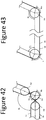
- the basics of the cable routing method used in this invention is illustrated in Figure 42 for the general case of having both cables La and Lb, composing the closed loop L, being routed through a general pivot joint.
- the cables La and Lb are wrapped around a set of pulleys, Im, called the "joint idler pulleys," which are concentric with the joint's axis of rotation.
- cables La, Lb must remain in contact with the joint idler pulleys at all times.
- auxiliary pulleys Ap and Ad may be added.
- Another solution to keep a constant cable length of the closed loop consists in compensating the length change not at the joint level but between the equivalent idler pulleys Im and Is of respective handle and end-effector as schematically shown in Figure 43 .
- both cables La, Lb are passing under Im and Is and, when the joint angle ⁇ j, ⁇ 'j, is changed, the constant length of the closed loop is guaranteed because the increase/reduction of ⁇ s is compensated by the reduction/increase of ⁇ m.
- the mechanical transmission may comprise rigid elements R1, R2, R3, instead of flexible elements C1, C2, to transmit motion between the handle link L3 and the end-effector link L2.
- Other embodiments can be achieved by combining flexible elements with rigid elements and/or geared components.
- Figures 12 to 14 show the articulated instrument 1 with different angular displacements at the proximal handle link 15 (and therefore, proximal end-effector link 6).
- the geometry of frame 5 allows for the movement of the handle 3 in its full range of motion.
- the actuation ⁇ 18 of the handle link 18 is able to produce simultaneous rotations ⁇ 7, ⁇ 8 on both the end-effector links 7, 8, with a certain movement amplification ratio.
- a second distal handle link 18' may exist, so that its actuation ⁇ 18' can actuate the end-effector link 7 by a rotation ⁇ 7 and the actuation ⁇ 18 of the handle link 18 is actuating uniquely the end-effector link 8 by a rotation ⁇ 8.
- the axis 42, around which the handle link 18 is able to rotate ⁇ 18 might be not parallel to the axis 10 around which the distal end-effector links 7, 8 are moving ⁇ 7, ⁇ 8, providing a different ergonomic position to the user.
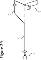
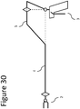
- Figures 28 to 31 show alternative kinematics of the articulated instrument 1 according to different embodiments of the present invention.
- the handle link 18 may be replaced by another handle link 19, whose axis of rotation 20 is perpendicular and non-intersecting with the axis 13 ( Figure 16 ), providing a different ergonomy to the user.
- a clamp element 21 may be used on the handle 3 in order to block the movement of the handle link 18 when it is brought to the "closed” position.
- the end-effector comprises a needle holder instrument and the user wants to apply high and constant gripping forces on needles when performing suturing tasks. Therefore, when the handle link 18 is brought ⁇ 18 to its "closed” position, its movement is blocked by a wedge/step geometry 21a (actuated by a system of miniature springs 22) of the clamp element 21 ( Figure 17 ). Then, in order to unlock the movement of the handle link 18, the user should press the clamp element 21 downwards, so that the handle link 18 can pass back through the wedge/step geometry 21a of the clamp element 21.
- the handle 3 may be provided with a spring element 23 that can bring the handle link 18 to an "opened” default position ( Figure 18 ) and apply a resistance torque when the handle link 18 is moving towards a "closing" direction.
- the external tube 4a composing the instrument shaft 4, can be easily and individually detached and attached to the articulated instrument 1 after each procedure.
- the internal structural element 4b is fixed directly to the frame 5 and the external tube 4a can be connected and disconnected from the internal structural element 4b by threaded surfaces or any other attachment mechanism. Therefore, with this architecture, the external tube 4a can be removed from the articulated instrument 1, without the need to disassemble other parts of the system, like the articulated end-effector 2 or the mechanical transmission elements 25, which remain completely operational without the external tube 4a. This feature facilitates tremendously the procedure to effectively clean and sterilize the articulated instrument 1, which can easily be performed by the hospital staff.
- the external tube 4a is in contact with a sealing element 24, which fills the gap between the internal surface of the external tube 4a and the internal structural element 4b.
- This sealing element 24 has little channels through which the transmission elements 25 can pass, guaranteeing the air-tightness of the articulated instrument 1.
- the distal part of the articulated instrument 1 may be able to be easily attached and detached to the proximal part of the articulated instrument 1.
- the attachment/ detachment between the distal 26 and the proximal 27 parts of the articulated instrument 1 can be done between the frame 5 and the handle 3 ( Figure 20 ).
- the attachment/ detachment between the distal 28 and the proximal 29 parts of the articulated instrument 1 can be done between the instrument shaft 4 and the frame 5 ( Figure 21 ).
- the detachable distal instrument 28 may be provided with a distal articulated end-effector 2, a proximal hub 30 and the instrument shaft 4, through which different mechanical elements 25 may pass, delivering motion to the different end-effector links 6, 7, 8 ( Figure 22 ) from the proximal hub 30.
- the distal part 28 of the surgical instrument 1 Since the distal part 28 of the surgical instrument 1 is partially entering the patient's body, it has to be sterile, just like the area in the vicinity of the patient.
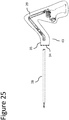
- the proximal part 29 of the articulated instrument 1 may not be sterile and therefore should be separated from the sterile instrument portions 28 by a sterile interface 43 which protects the sterile area from the non-sterile components 29 of the articulated instrument 1 ( Figure 25 ).
- the sterile interface 43 comprises two main components: a flexible sleeve 35, which covers the moving links of the proximal part 29 of the articulated instrument 1 and a rigid connector 35, which i) guarantees that the sterile distal part 28 of the articulated instrument 1 is not directly touching the non-sterile components of the proximal part 29, ii) enables attachment/detachment between the distal 28 and the proximal 29 parts of the articulated instrument 1, and iii) ensures the connection/disconnection of the mechanical transmission systems that deliver motion to the end-effector links 6, 7, 8.
- Figure 26 shows how the rigid connector 34 can be disposed and operationally mounted between the proximal hub 30 and the proximal part 29 of the articulated instrument 1.
- the mechanical transmission systems that deliver motion to the end-effector links 6, 7, 8, three cylindrical elements 36, 37, 38, from the proximal part 29 of the articulated instrument 1 are inserted on three miniature cups 39, 40, 41 of the rigid connector 34, which are then inserted on the rotating elements 31, 32, 33. In this way, it can be guaranteed that the sterile surgical instrument 28 is not directly touching non-sterile components.
- the movement of some of the three cylindrical elements 36, 37, 38, from the proximal part 29 of the articulated instrument 1, may be constrained so that some degrees-of-freedom of the end-effector 2 can be locked/unlocked in their range of movement, allowing for instance the use of the articulated instrument 1 as a standard laparoscopic instrument, with a single degree-of-freedom at the end-effector.
- the articulated hand-held medical instrument of the present invention is designed to be used in a full range of minimally invasive surgical procedures in combination with standard laparoscopic equipment.
- the inventive instrument may optionally be inserted through a trocar and its movements inside the patient's body may be tracked with an available endoscopic camera.
- the articulated hand-held medical instrument may be used in a range of port arrangements in minimally invasive surgical procedures.
- the articulated instrument 1 can assume other kinematics, like the kinematic models shown in Figures 28 to 31 .
- the central rotation point 14 of the articulated handle 3 is not coincident with the central wrist point 43 of the user 44.
- these positional offsets ⁇ x, ⁇ y (and possibly ⁇ z) can create positional mismatches (also known as "parasitic movements") between the movements applied to the handle 3 and the movements generated at the end-effector 2.
- a pure rotation performed by the user's hand at the handle 3 might create a composed movement, of rotation plus a translation, of the end-effector 2. Therefore, in order to compensate for that, the central rotation point 14 and the central wrist point 43 have to be aligned.
- Figures 38 and 39 show two non claimed embodiments using two different kinematic models.
- the articulated instrument 1 of Figure 38 uses a double parallelogram mechanism 47 to achieve its RCM, where the central rotation point 14 is set to be substantially coincident to the central wrist point 44 of the user 43.
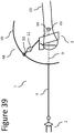
- the articulated instrument 1 of Figure 39 uses a spherical mechanism, having a circular track 49 as the movement base, whose center is aligned with the axis 9 of the instrument shaft 4.
- a radial sliding element 50 comprises a collinear rotational joint 51 and is always aligned with the RCM (the central rotation point 14) at the center of the circular track 49.
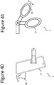
- the handle 3 of the articulated instrument 1 may be compatible with handle links 17 and 18 of multiple shapes and sizes. Therefore, while in the embodiment of Figure 40 , the handle links 17 and 18 may have a joystick-like or pistol-grip-like shape, in the embodiment shown in Figure 41 , the handle links 17 and 18 have a scissors-like or needle-holder-like configuration.
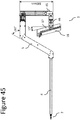
- Figures 44 to 46 show three different views (with main dimensions) of a possible embodiment of the current invention. These figures showa detailed design version of the embodiment of Figures 35 to 37 , with the kinematic model of Figures 33 and 34 .
- the articulated instrument 1 may be, in the main, constructed of aluminum components, although the invasive part of the instrument should be mainly constructed of medical grade stainless steel and polymers.
- the mechanical transmission is essentially constructed of tungsten ropes, although steel or polymeric ropes could also be used in some specific situations, depending on the target number of cleaning and sterilization cycles that the instrument should support.
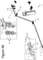
- Figure 48 shows the transmission of motion between the handle 3 and end-effector 2 for the proximal degree of freedom. Joints around the axes 11 and 13 are connected by a cable 52 in a single closed loop configuration (in some embodiments, it may comprise two segments of cable 52a and 52b) which runs from a driving pulley C13 connected to the proximal handle link 45 and passing through 3 sets of guiding pulleys G1, G2 and G3 up to a driven pulley C6, connected to the proximal end-effector link 6.
- the sets of guiding pulleys are used to shape the path of the transmission cables to the geometry of the frame 5 or handle links.
- Figure 49 shows the transmission of motion between the handle 3 and end-effector 2 for a first distal degree of freedom.
- Joints around the axes 10 and 12 are connected by a cable 53 in a single closed loop configuration (in some embodiments, it may comprise two segments of cable 53a and 53b) which runs from a driving pulley C12 up to a driven pulley C10, connected to the proximal end-effector link 7.
- the closed loop cable 53 passes through 6 sets of guiding pulleys G1, G2, G3, G4, G5, G6 and a set of joint idle pulleys JIP.
- actuation shaft 56 ( Figures 50 and 51 ), which transmits the actuation input movement from the handle link 18.
- Handle link 18 is rigidly attached to an actuation link 57, which is connected by a linkage system 58 to the actuation shaft 56.
- a spring system 59 is permanently acting on the linkage system 58, bringing the actuation link 57 to a default open position.
- the actuation link 57 can be temporarily blocked by a spring-actuated ratcheting mechanism 60, which can be deactivated by pressing up the thumb trigger 61.
Landscapes
- Health & Medical Sciences (AREA)
- Surgery (AREA)
- Life Sciences & Earth Sciences (AREA)
- Engineering & Computer Science (AREA)
- Medical Informatics (AREA)
- Biomedical Technology (AREA)
- Heart & Thoracic Surgery (AREA)
- Nuclear Medicine, Radiotherapy & Molecular Imaging (AREA)
- Molecular Biology (AREA)
- Animal Behavior & Ethology (AREA)
- General Health & Medical Sciences (AREA)
- Public Health (AREA)
- Veterinary Medicine (AREA)
- Ophthalmology & Optometry (AREA)
- Robotics (AREA)
- Surgical Instruments (AREA)
Description
- The present invention relates to the field of remotely actuated mechanical systems, more particularly to surgical instruments, and most particularly to articulated hand-held surgical instruments. More specifically, this invention relates to articulated hand-held surgical instruments primarily designed to be used in minimally invasive surgical procedures. The inventive surgical instruments are designed to be used in a full range of minimally invasive surgical procedures and with standard equipment, such as trocars and endoscopic cameras. The articulated hand-held surgical instruments are designed to provide greater reach, range of motion and dexterity than that accessible with the use of standard laparoscopic instruments.
- Open surgery is still the standard technique for most surgical procedures. It has been used by the medical community for several decades and consists of performing the surgical tasks through a long incision in the abdomen, through which traditional surgical tools are inserted. However, due to the long incision, this approach is extremely invasive for the patients, resulting in substantial blood loss during the surgery and long and painful recovery periods at the hospital.
- In order to reduce the invasiveness of open surgery, laparoscopy, a minimally invasive technique, was developed. Instead of a single long incision, four to five small incisions are made in the patient through which appropriately sized surgical instruments and endoscopic cameras are inserted. Because of the low invasiveness, this technique reduces blood loss and shortens hospital stays and pain. When performed by experienced surgeons, this technique can attain clinical outcomes similar to open surgery. However, despite the above-mentioned advantages, laparoscopy requires extremely advanced surgical skills to manipulate the rigid and long instrumentation. The entry incision acts as a point of rotation, decreasing the surgeon's freedom for positioning and orientating the instruments inside the patient. The movements of the surgeon's hand about this incision are inverted and scaled-up relative to the instrument tip ("fulcrum effect"), which removes dexterity, sensibility and magnifies the tremors of the surgeon's hands. In addition, these long and straight instruments force surgeons to work in a uncomfortable posture, which can be tremendously tiring during several hours of operation and result in stress and discomfort for hands, arms and body. Therefore, due to these drawbacks of laparoscopic instrumentation, these minimally invasive techniques are mainly limited to use in simple surgeries, while only a small minority of surgeons is able to use them in complex procedures.
- To overcome these limitations, surgical robotic systems were developed to provide an easier-to-use approach to complex minimally invasive surgeries. By means of a computerized robotic interface, these systems enable the performance of remote laparoscopy wherein the surgeon sits at a console manipulating two master manipulators to perform the operation through several small incisions. Like laparoscopy, the robotic approach is also minimally invasive, bringing several advantages over open surgery in terms of pain, blood loss, and recovery time. In addition, it also offers better ergonomy for the surgeon compared to open and laparoscopic techniques. However, although being technically easier, robotic surgery brings several negative aspects. A major disadvantage of these systems is related to the extremely high complexity of existing robotic devices, which are composed of complex mechanical and electronic systems, leading to huge costs of acquisition and maintenance, which are not affordable for the majority of surgical departments worldwide. Another drawback of these systems comes from the fact that current surgical robots are very large, competing for precious space within the operating room environment and significantly increasing preparation time. Access to the patient is thus impaired, which, together with a lack of force-feedback, raises safety concerns.
- In addition to robotic systems, several hand-held laparoscopic instruments are known. These instruments provide access to the surgical field without the need for an expensive and cumbersome robotic system, but they often provide poor ergonomy to the user.
- There are known examples of hand-held, articulated surgical instruments. However, they present significant drawbacks in their designs. For example, one known articulated instrument (ref) must be attached to the user's forearm by a frame, making its use cumbersome and likely tiring, given that every movement must involve the user moving his entire forearm, which needs to be geometrically aligned with the instrument's shaft. Other known articulated instruments (refs) require the manipulation of knobs or similar elements on the device handle to produce corresponding movements in an end-effector. Such arrangement does not allow for a natural replication of user hand movements.
-
US 2012/277762 A1 discloses a handheld surgical instrument having an articulated handle, an articulated end effector, a structural frame and a flexible mechanical transmission system. - Accordingly, an aim of the present invention is to provide an articulated hand-held medical instrument that allows for a natural replication of user hand movements on the instrument handle at an end effector. The instrument is to allow for good ergonomy and ease of use as compared to known hand-held articulated instruments.
- Theses aims and other advantages are achieved by a new articulated hand-held medical instrument. The articulated hand-held medical instrument of the present invention is primarily intended to be used in minimally invasive surgical procedures. A surgical instrument according to the invention is defined in
claim 1. Preferred embodiments of the invention are defined in the dependent claims. - The articulated hand-held medical instrument comprises a frame, a proximal handle and a distal end-effector. The proximal handle is joined to the distal end-effector by an instrument tube and a structural frame. The instrument tube may optionally be introduced to the patient's body during a minimally invasive surgical procedure through a trocar or other standard piece of equipment.
- The proximal handle of the articulated hand-held surgical instrument is made up of a series of handle links connected by handle joints. The distal end-effector element is generally made up of a number of end-effector links connected by end-effector joints. Mechanical transmission means transmit user motions performed on the proximal handle to the distal end- effector. In this way, the articulated hand-held surgical instrument has a master-slave architecture allowing for the replication of user hand movements on the proximal handle at the distal end-effector. Taken in conjunction with the multiple links and degrees of freedom, this architecture allows for greater dexterity and ergonomy than that accessible with standard laparoscopic instruments.
- The invention will be better understood according to the following detailed description of several embodiments with reference to the attached drawings, in which:
-
Figure 1 shows a perspective view of the articulated instrument according to an exemplary embodiment. -
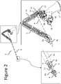
Figure 2 shows a detailed perspective view of the articulated instrument according to an exemplary embodiment; -
Figure 3 shows a detailed side view of the articulated instrument according to an exemplary embodiment; -
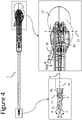
Figure 4 shows a detailed top view of the articulated instrument according to an exemplary embodiment; -
Figure 5 shows the distal end-effector of the articulated instrument according to an exemplary embodiment in a first active position; -
Figure 6 shows the distal end-effector of the articulated instrument according to an exemplary embodiment in a second active position; -
Figure 7 shows the distal end-effector of the articulated instrument according to an exemplary embodiment in a third active position; -
Figure 8 shows the distal end-effector of the articulated instrument according to an exemplary embodiment in a fourth active position; -
Figure 9 shows the distal end-effector of the articulated instrument according to an exemplary embodiment in a fifth active position; -
Figure 10 shows a simplified path of a flexible transmission system actuating a distal end-effector articulation of the articulated instrument according to an exemplary embodiment; -
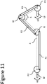
Figure 11 shows a simplified path of a rigid transmission system actuating a distal end-effector articulation of the articulated instrument according to a different exemplary embodiment; -
Figure 12 shows the articulated instrument according to an exemplary embodiment in a first active position; -
Figure 13 shows the articulated instrument according to an exemplary embodiment in a second active position; -
Figure 14 shows the articulated instrument according to an exemplary embodiment in a third active position; -
Figure 15 illustrates the actuation of the two distal end-effector links of the articulated instrument according to an exemplary embodiment; -
Figure 16 shows a schematic side view of the articulated instrument, according to an exemplary embodiment; -
Figure 17 shows a perspective view of a clamp system used in the proximal handle of the articulated instrument, according to an exemplary embodiment; -
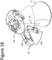
Figure 18 shows a perspective view of a spring system used in the proximal handle of the articulated instrument, according to an exemplary embodiment; -
Figure 19 shows a procedure through which an external tube of an instrument shaft can be assembled and disassembled on the articulated instrument according to an exemplary embodiment; -
Figure 20 shows a distal part of an articulated instrument detached from the proximal part of the articulated instrument according to an exemplary embodiment; -
Figure 21 shows a distal part of an articulated instrument detached from the proximal part of the articulated instrument according to another exemplary embodiment; -
Figure 22 shows a detachable distal part of an articulated instrument according to an exemplary embodiment; -
Figure 23 shows the rotational elements of an interface portion of a distal part of the articulated instrument according to an exemplary embodiment; -
Figure 24 shows the rotational kinematics of an interface portion of a distal part of the articulated instrument according to an exemplary embodiment; -
Figure 25 shows schematically the sterile interface between the distal and proximal parts of the articulated instrument according to an exemplary embodiment; -
Figure 26 shows a perspective view of a rigid connector composing a sterile interface operationally mounted between the distal and proximal parts of the articulated instrument according to an exemplary embodiment; -
Figure 27 illustrates the actuation of the two distal end-effector links of the articulated instrument according to an exemplary embodiment; -
Figure 28 shows an alternative kinematics of the articulated instrument according to an embodiment of the present invention; -
Figure 29 shows an alternative kinematics of the articulated instrument according to an exemplary embodiment; -
Figure 30 shows an alternative kinematics of the articulated instrument according to an exemplary embodiment; -
Figure 31 shows an alternative kinematics of the articulated instrument according to an exemplary embodiment. -
Figure 32 shows a kinematic model of an exemplary embodiment displaying the position of the user's wrist joint relative to that of a centre of rotation of the handle. -
Figures 33 and34 show alternative kinematic models of embodiments of the present invention displaying alignment of the user's wrist joint relative to the centre of rotation of the handle. -
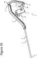
Figures 35 ,36 and37 show embodiments of the present invention where the user's wrist is in alignment with the centre of rotation of the handle. -
Figures 38 and39 show kinematic models of exemplary embodiments including a wrist alignment concept. -
Figures 40 and 41 show representative handle links that may be used in accordance with embodiments of the present invention. -
Figure 42 shows a schematic view of a cable rooting method to maintain a closed loop with a constant length, shown at the joint level, in accordance with various embodiments of the present invention; -
Figure 43 shows a schematic view of another cable rooting method to maintain a closed loop with a constant length, shown at the level of equivalent handle/end-effector joints, in accordance with various embodiments of the present invention; -
Figures 44 ,45 and46 show different views, with main dimensions, of a detailed design of an embodiment of the present invention. -
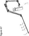
Figures 47 ,48 and49 show the mechanical transmission elements of the different degrees-of-freedom of the instrument, in accordance with various embodiments of the present invention. -
Figures 50 and 51 show detailed views of the instrument's actuation system, in accordance with various embodiments of the present invention. - The articulated
instrument 1 ofFigure 1 , is intended to be used in minimally invasive surgical procedures. - One of the key features of this type of articulated
instrument 1 lies in its master-slave architecture, which enables the replication of the user hand movements, on a proximal handle 3 (the master), by a distal end-effector 2 (the slave) inside the patient's body. - According to
Figures 1 ,2 ,3 and4 , the articulatedinstrument 1 comprises: i) aproximal handle 3 having a number ofhandle links axes frame 5, structurally connecting theproximal handle 3 to the distal portion of the articulatedinstrument 1; iii) a distal end-effector 2 having a number of end-effector links axes instrument shaft 4, connecting the distal end of theframe 5 to the distal end-effector 2. More particularly, the kinematic chain formed by the plurality of articulated end-effector links effector joints effector 2, may be substantially identical to the kinematic chain formed by the plurality of articulatedhandle links proximal handle 3. As can be seen inFigure 2 , theaxes central rotation point 14, which is kinematically equivalent to a spherical joint. - Referring to
Figures 2 ,3 and4 , the end-effector 2 is connected to the distal extremity of theinstrument shaft 4 by a proximal end-effector j oint, which allows the rotation of the proximal end-effector link 6 by theproximal axis 11 in such a manner that the orientation of the proximal end-effector link 6 with respect to themain axis 9 of theinstrument shaft 4 can be changed. The distal end-effector links effector link 6 by two distal joints, having coincident axes of rotation, which are represented by thedistal axis 10. Thisdistal axis 10 is substantially perpendicular and non-intersecting with theproximal axis 11 and substantially intersects themain axis 9 of theinstrument shaft 9.Figures 5 to 7 show the end-effector 2 with different angular displacements at the proximal end-effector link 6. - By actuating the two distal joints, the two distal end-
effector links distal axis 10, with respect to the plane containing themain axis 9 and thedistal axis 10, by the angles θ7, θ8. Consequently, through the combination of rotations θ7 and θ8, it is possible to operate thesurgical instrument 1, in such a manner as to provide orientation motions between the end effector and the instrument shaft 4 (Figure 8 ) and to accomplish its "open/close" function (Figure 9 ). - The articulated
instrument 1 further comprises mechanical transmission systems arranged to kinematically connect the distal end-effector 2 with theproximal handle 3 such that the movement (angle of joint) applied on each handle joint of theproximal handle 3 is reproduced by the corresponding end-effector joint of the distal end-effector 2. - For each degree of freedom of the articulated
instrument 1, different types of mechanical transmission can be used. In order to minimize the system's overall friction and inertia, certain embodiments of the current invention may use a mechanical transmission in the form of pulley-routed flexible elements, where each driven pulley of the distal end-effector 2 is connected to the respective driving pulley of theproximal handle 2, by a closed cable loop transmission. As can be seen inFigure 10 , the action of the user creating a rotation α3 on a general handle link L3 produces a rotation α3 on the handle pulley P3, which is directly connected to the handle link L3. Then, the mechanical transmission system, composed by the closed cable loop comprising cables C1 and C2, passes by theframe 5 and theinstrument shaft 4 and is able to kinematically connect the handle pulley P3 to the end- effector pulley P2 (a system ofidle pulleys - The transmission of the movement between each handle pulley and the corresponding end-effector pulley in the aforementioned embodiments, by using this kind of mechanical transmission, may present certain drawbacks pertaining to kinematic and dynamic coupling between the driven and the driving pulleys. Furthermore, the adoption of a closed loop cable transmission requires that the overall length of the cable route must be kept constant, for all possible handle/end-effector configurations, independently of the motion performed by the driving pulleys of the articulated
handle 2. In this sense, the aforementioned embodiments will be operational but may not accommodate all possible use cases. - Therefore, cables must be routed through joint idler pulleys while maintaining constant cable length. The basics of the cable routing method used in this invention is illustrated in
Figure 42 for the general case of having both cables La and Lb, composing the closed loop L, being routed through a general pivot joint. The cables La and Lb are wrapped around a set of pulleys, Im, called the "joint idler pulleys," which are concentric with the joint's axis of rotation. To maintain constant cable length of the closed loop, cables La, Lb must remain in contact with the joint idler pulleys at all times. In this way, if the joint angle θj is reduced, the length of the superior segment of La, in contact with the idler pulley Im will decrease and the inferior segment of Lb will increase, by the same value, guaranteeing the constant length of the cable closed loop. In addition, in order to keep a permanent contact between the cables La and Lb with the idler pulleys Im, auxiliary pulleys Ap and Ad may be added. - Another solution to keep a constant cable length of the closed loop consists in compensating the length change not at the joint level but between the equivalent idler pulleys Im and Is of respective handle and end-effector as schematically shown in
Figure 43 . In this case, both cables La, Lb are passing under Im and Is and, when the joint angle θj, θ'j, is changed, the constant length of the closed loop is guaranteed because the increase/reduction of θs is compensated by the reduction/increase of θm. - In a different embodiment, as is conceptually illustrated in
Figure 11 , the mechanical transmission may comprise rigid elements R1, R2, R3, instead of flexible elements C1, C2, to transmit motion between the handle link L3 and the end-effector link L2. Other embodiments can be achieved by combining flexible elements with rigid elements and/or geared components. -
Figures 12 to 14 show the articulatedinstrument 1 with different angular displacements at the proximal handle link 15 (and therefore, proximal end-effector link 6). The geometry offrame 5 allows for the movement of thehandle 3 in its full range of motion. - In an embodiment, the actuation θ18 of the
handle link 18 is able to produce simultaneous rotations θ7, θ8 on both the end-effector links Figure 15 , a second distal handle link 18' may exist, so that its actuation θ18' can actuate the end-effector link 7 by a rotation θ7 and the actuation θ18 of thehandle link 18 is actuating uniquely the end-effector link 8 by a rotation θ8. - In a different embodiment, as shown in
Figure 27 , theaxis 42, around which thehandle link 18 is able to rotate θ18 might be not parallel to theaxis 10 around which the distal end-effector links Figures 28 to 31 show alternative kinematics of the articulatedinstrument 1 according to different embodiments of the present invention. - In another embodiment, the
handle link 18 may be replaced by anotherhandle link 19, whose axis ofrotation 20 is perpendicular and non-intersecting with the axis 13 (Figure 16 ), providing a different ergonomy to the user. - As can be seen in
Figure 17 , aclamp element 21 may be used on thehandle 3 in order to block the movement of thehandle link 18 when it is brought to the "closed" position. This is particularly useful when the end-effector comprises a needle holder instrument and the user wants to apply high and constant gripping forces on needles when performing suturing tasks. Therefore, when thehandle link 18 is brought θ18 to its "closed" position, its movement is blocked by a wedge/step geometry 21a (actuated by a system of miniature springs 22) of the clamp element 21 (Figure 17 ). Then, in order to unlock the movement of thehandle link 18, the user should press theclamp element 21 downwards, so that thehandle link 18 can pass back through the wedge/step geometry 21a of theclamp element 21. - In another embodiment, the
handle 3 may be provided with a spring element 23 that can bring thehandle link 18 to an "opened" default position (Figure 18 ) and apply a resistance torque when thehandle link 18 is moving towards a "closing" direction. - As can be seen in
Figure 19 , theexternal tube 4a, composing theinstrument shaft 4, can be easily and individually detached and attached to the articulatedinstrument 1 after each procedure. Referring toFigure 19 , the internalstructural element 4b is fixed directly to theframe 5 and theexternal tube 4a can be connected and disconnected from the internalstructural element 4b by threaded surfaces or any other attachment mechanism. Therefore, with this architecture, theexternal tube 4a can be removed from the articulatedinstrument 1, without the need to disassemble other parts of the system, like the articulated end-effector 2 or themechanical transmission elements 25, which remain completely operational without theexternal tube 4a. This feature facilitates tremendously the procedure to effectively clean and sterilize the articulatedinstrument 1, which can easily be performed by the hospital staff. - Towards a more distal region of the
instrument shaft 4, theexternal tube 4a is in contact with a sealingelement 24, which fills the gap between the internal surface of theexternal tube 4a and the internalstructural element 4b. This sealingelement 24 has little channels through which thetransmission elements 25 can pass, guaranteeing the air-tightness of the articulatedinstrument 1. - In order to farther facilitate the cleaning and sterilization procedure, the distal part of the articulated
instrument 1 may be able to be easily attached and detached to the proximal part of the articulatedinstrument 1. In one possible embodiment of the current invention, the attachment/ detachment between the distal 26 and the proximal 27 parts of the articulatedinstrument 1 can be done between theframe 5 and the handle 3 (Figure 20 ). However, in another embodiment of the current invention, the attachment/ detachment between the distal 28 and the proximal 29 parts of the articulatedinstrument 1 can be done between theinstrument shaft 4 and the frame 5 (Figure 21 ). - In the above mentioned embodiment, the detachable
distal instrument 28 may be provided with a distal articulated end-effector 2, aproximal hub 30 and theinstrument shaft 4, through which differentmechanical elements 25 may pass, delivering motion to the different end-effector links Figure 22 ) from theproximal hub 30. - With reference to
Figures 23 and24 , the movement is transmitted to each one of the three distal articulations of the articulatedinstrument 1 by arotating element axis 9 and is connected to one of thetransmission elements 25. As a result, when therotating element axis 9, a rotation α1, α2, α3 is transmitted to the respective end-effector link - Since the
distal part 28 of thesurgical instrument 1 is partially entering the patient's body, it has to be sterile, just like the area in the vicinity of the patient. On the other hand, theproximal part 29 of the articulatedinstrument 1 may not be sterile and therefore should be separated from thesterile instrument portions 28 by asterile interface 43 which protects the sterile area from thenon-sterile components 29 of the articulated instrument 1 (Figure 25 ). - The
sterile interface 43 comprises two main components: aflexible sleeve 35, which covers the moving links of theproximal part 29 of the articulatedinstrument 1 and arigid connector 35, which i) guarantees that the steriledistal part 28 of the articulatedinstrument 1 is not directly touching the non-sterile components of theproximal part 29, ii) enables attachment/detachment between the distal 28 and the proximal 29 parts of the articulatedinstrument 1, and iii) ensures the connection/disconnection of the mechanical transmission systems that deliver motion to the end-effector links -
Figure 26 shows how therigid connector 34 can be disposed and operationally mounted between theproximal hub 30 and theproximal part 29 of the articulatedinstrument 1. In order to connect/disconnect the mechanical transmission systems that deliver motion to the end-effector links cylindrical elements proximal part 29 of the articulatedinstrument 1, are inserted on threeminiature cups rigid connector 34, which are then inserted on therotating elements surgical instrument 28 is not directly touching non-sterile components. - In other embodiments, the movement of some of the three
cylindrical elements proximal part 29 of the articulatedinstrument 1, may be constrained so that some degrees-of-freedom of the end-effector 2 can be locked/unlocked in their range of movement, allowing for instance the use of the articulatedinstrument 1 as a standard laparoscopic instrument, with a single degree-of-freedom at the end-effector. - The articulated hand-held medical instrument of the present invention is designed to be used in a full range of minimally invasive surgical procedures in combination with standard laparoscopic equipment. For example, the inventive instrument may optionally be inserted through a trocar and its movements inside the patient's body may be tracked with an available endoscopic camera. In addition, the articulated hand-held medical instrument may be used in a range of port arrangements in minimally invasive surgical procedures.
- The articulated
instrument 1 can assume other kinematics, like the kinematic models shown inFigures 28 to 31 . - As illustrated in
Figure 32 , in most of the embodiments (and kinematic models) described up to this point, thecentral rotation point 14 of the articulatedhandle 3 is not coincident with thecentral wrist point 43 of theuser 44. However, these positional offsets Δx, Δy (and possibly Δz) can create positional mismatches (also known as "parasitic movements") between the movements applied to thehandle 3 and the movements generated at the end-effector 2. In particular, a pure rotation performed by the user's hand at thehandle 3 might create a composed movement, of rotation plus a translation, of the end-effector 2. Therefore, in order to compensate for that, thecentral rotation point 14 and thecentral wrist point 43 have to be aligned. In order to achieve this, other kinematic models (like the ones ofFigures 33 ,38 and39 ) can be used on the articulatedinstrument 1 of the current invention so that thecentral rotation point 14 is located in the free space and not within the structure of the movinglinks Figures 35 ,36 and37 , there are three revolute joints whoseaxes instrument 1 can be set so that the central rotation point 14 (or RCM) is substantially coincident to thecentral wrist point 44 of theuser 43.Figures 36 and37 show a side and top view of this alignment. -
Figures 38 and39 show two non claimed embodiments using two different kinematic models. The articulatedinstrument 1 ofFigure 38 uses adouble parallelogram mechanism 47 to achieve its RCM, where thecentral rotation point 14 is set to be substantially coincident to thecentral wrist point 44 of theuser 43. The articulatedinstrument 1 ofFigure 39 uses a spherical mechanism, having acircular track 49 as the movement base, whose center is aligned with theaxis 9 of theinstrument shaft 4. Mounted on thecircular track 49, aradial sliding element 50 comprises a collinear rotational joint 51 and is always aligned with the RCM (the central rotation point 14) at the center of thecircular track 49. - In order to provide an ergonomic manipulation and gripping functionality to the user, the
handle 3 of the articulatedinstrument 1 may be compatible withhandle links Figure 40 , the handle links 17 and 18 may have a joystick-like or pistol-grip-like shape, in the embodiment shown inFigure 41 , the handle links 17 and 18 have a scissors-like or needle-holder-like configuration. -
Figures 44 to 46 show three different views (with main dimensions) of a possible embodiment of the current invention. These figures showa detailed design version of the embodiment ofFigures 35 to 37 , with the kinematic model ofFigures 33 and34 . - In order to be as light in weight as possible, the articulated
instrument 1 may be, in the main, constructed of aluminum components, although the invasive part of the instrument should be mainly constructed of medical grade stainless steel and polymers. The mechanical transmission is essentially constructed of tungsten ropes, although steel or polymeric ropes could also be used in some specific situations, depending on the target number of cleaning and sterilization cycles that the instrument should support. - The mechanical transmission elements for each one of the three degrees of freedom of the instrument are shown are shown in
Figure 47 to Figure 49 , as described in more detail below. -
Figure 48 shows the transmission of motion between thehandle 3 and end-effector 2 for the proximal degree of freedom. Joints around theaxes cable 52 in a single closed loop configuration (in some embodiments, it may comprise two segments of cable 52a and 52b) which runs from a driving pulley C13 connected to theproximal handle link 45 and passing through 3 sets of guiding pulleys G1, G2 and G3 up to a driven pulley C6, connected to the proximal end-effector link 6. The sets of guiding pulleys are used to shape the path of the transmission cables to the geometry of theframe 5 or handle links. -
Figure 49 shows the transmission of motion between thehandle 3 and end-effector 2 for a first distal degree of freedom. Joints around theaxes cable 53 in a single closed loop configuration (in some embodiments, it may comprise two segments of cable 53a and 53b) which runs from a driving pulley C12 up to a driven pulley C10, connected to the proximal end-effector link 7. On their path from the driving pulley C12 to the driven pulley C6, theclosed loop cable 53 passes through 6 sets of guiding pulleys G1, G2, G3, G4, G5, G6 and a set of joint idle pulleys JIP. Although this degree-of-freedom is driven by pulley C12, the closed cable loop is not directly attached to it. Instead they are attached to adistal actuation pulley 55, which couples the movement of the two distal degrees-of-freedom (shown inFigures 8 and 9 ) so that they perform the actuation of the instrument in parallel. The motion transmission between thehandle 3 and end-effector 2 for the second distal degree of freedom is analogous, with a similar arrangement of cable loops and pulleys. - Attached to the
distal actuation pulley 55, there is an actuation shaft 56 (Figures 50 and 51 ), which transmits the actuation input movement from thehandle link 18. Handlelink 18 is rigidly attached to anactuation link 57, which is connected by alinkage system 58 to theactuation shaft 56. Aspring system 59 is permanently acting on thelinkage system 58, bringing theactuation link 57 to a default open position. When brought to its maximum closed position, theactuation link 57 can be temporarily blocked by a spring-actuatedratcheting mechanism 60, which can be deactivated by pressing up thethumb trigger 61. - While this invention has been shown and described with reference to particular embodiments thereof, it will be understood by those skilled in the art that various changes in form and details may be made therein without departing from the scope of the invention as defined by the appended claims.
Claims (15)
- A handheld surgical instrument comprising:an instrument shaft (4) having a proximal end and a distal end;an articulated handle (3);an articulated end effector (2) connected to the distal end of the instrument shaft;a structural frame (5); anda flexible mechanical transmission system connecting the articulated handle to the articulated end effector such that motion applied to the articulated handle is reproduced at the articulated end effector,wherein the articulated end effector comprises at least three orientation or actuation degrees of freedom, whereinthe structural frame has a proximal end mounted on the articulated handle and a distal end coupled to the proximal end of the instrument shaft, and characterised in thatthe structural frame comprises three joints, each of the three joints having an axis (9, 12, 13) that intersects at a remote center of motion (14) of the handheld surgical instrument (1), the remote center of motion coincident to a central point (44) of a user's wrist.
- The handheld surgical instrument of claim 1, wherein the flexible mechanical transmission system comprises a system of cables (C1, C2, 52, 53) and pulleys (P2, P3, I1, I2, C6, C10, C12, C13, G1, G2, G3, G4, G5, G6, 55) disposed at the articulated handle and articulated end effector.
- The handheld surgical instrument of claims 1 or 2, wherein the articulated handle comprises a plurality of handle links (15, 17, 18) connected by a corresponding plurality of handle joints (12, 13, 42) and wherein the articulated end effector comprises a plurality of end-effector links (6, 7, 8) connected by a corresponding plurality of end effector joints, and wherein the number of handle links is equal to the number of end-effector links.
- The handheld surgical instrument of claim 3, wherein motion applied to a particular handle link is reproduced at the corresponding end-effector link.
- The handheld surgical instrument of any of the preceding claims, wherein the handle comprises a joystick-like or pistol-grip-like shape.
- The handheld surgical instrument of any of the preceding claims, wherein a geometry of the structural frame allows alignment of the human user's wrist with the remote center of motion of the handheld surgical instrument.
- The handheld surgical instrument of any of the preceding claims, wherein the geometry of the structural frame allows the articulated handle a full range of movement without colliding with the instrument shaft.
- The handheld surgical instrument of any of the preceding claims, wherein the flexible mechanical transmission system follows a continuous path from a proximal end of the articulated handle to the distal
end of the articulated handle and then from the proximal to the distal end of the structural frame and then from the proximal to the distal end of the instrument shaft and then from a proximal end of the articulated end-effector to a distal end of the articulated end effector. - The handheld surgical instrument of any of the preceding claims, wherein the structural frame consists of two links .
- The handheld surgical instrument of any of the preceding claims, wherein the handle comprises a scissors-like or needle-holder-like configuration.
- The handheld surgical instrument of claim 2, wherein the flexible mechanical transmission system comprises a closed loop configuration.
- The handheld surgical instrument of any of the preceding claims, wherein the at least three degrees of freedom of the articulated end effector comprise at least two orientational degrees of freedom and at least one actuation degree of freedom.
- The handheld surgical instrument of claim 12, wherein at least two of the orientational degrees of freedom have a serial kinematic disposition.
- The handheld surgical instrument of claim 12 or 13, wherein the at least one actuation degree of freedom is disposed in parallel to the orientational degrees of freedom.
- The handheld surgical instrument of any of the preceding claims, wherein the flexible mechanical transmission system comprises cables made from steel or tungsten.
Applications Claiming Priority (3)
| Application Number | Priority Date | Filing Date | Title |
|---|---|---|---|
| US201562145454P | 2015-04-09 | 2015-04-09 | |
| US201662280736P | 2016-01-20 | 2016-01-20 | |
| PCT/IB2016/000542 WO2016162751A1 (en) | 2015-04-09 | 2016-04-11 | Articulated hand-held instrument |
Publications (2)
| Publication Number | Publication Date |
|---|---|
| EP3280337A1 EP3280337A1 (en) | 2018-02-14 |
| EP3280337B1 true EP3280337B1 (en) | 2019-11-13 |
Family
ID=56289537
Family Applications (1)
| Application Number | Title | Priority Date | Filing Date |
|---|---|---|---|
| EP16733181.8A Active EP3280337B1 (en) | 2015-04-09 | 2016-04-11 | Articulated hand-held instrument |
Country Status (3)
| Country | Link |
|---|---|
| US (1) | US10363055B2 (en) |
| EP (1) | EP3280337B1 (en) |
| WO (1) | WO2016162751A1 (en) |
Families Citing this family (31)
| Publication number | Priority date | Publication date | Assignee | Title |
|---|---|---|---|---|
| US10405936B2 (en) | 2008-04-11 | 2019-09-10 | The Regents Of The University Of Michigan | Parallel kinematic mechanisms with decoupled rotational motions |
| US10092359B2 (en) | 2010-10-11 | 2018-10-09 | Ecole Polytechnique Federale De Lausanne | Mechanical manipulator for surgical instruments |
| US9696700B2 (en) | 2011-07-27 | 2017-07-04 | Ecole Polytechnique Federale De Lausanne | Mechanical teleoperated device for remote manipulation |
| WO2016030767A1 (en) | 2014-08-27 | 2016-03-03 | Distalmotion Sa | Surgical system for microsurgical techniques |
| EP3232977B1 (en) | 2014-12-19 | 2020-01-29 | DistalMotion SA | Docking system for mechanical telemanipulator |
| EP3232974B1 (en) | 2014-12-19 | 2018-10-24 | DistalMotion SA | Articulated handle for mechanical telemanipulator |
| EP4289385A3 (en) | 2014-12-19 | 2024-03-27 | DistalMotion SA | Surgical instrument with articulated end-effector |
| EP3232973B1 (en) | 2014-12-19 | 2020-04-01 | DistalMotion SA | Sterile interface for articulated surgical instruments |
| EP3653145B1 (en) | 2014-12-19 | 2024-01-24 | DistalMotion SA | Reusable surgical instrument for minimally invasive procedures |
| US11896336B2 (en) | 2015-02-17 | 2024-02-13 | Livsmed Inc. | Instrument for surgery |
| WO2016161449A1 (en) | 2015-04-03 | 2016-10-06 | The Regents Of The University Of Michigan | Tension management apparatus for cable-driven transmission |
| WO2016162752A1 (en) | 2015-04-09 | 2016-10-13 | Distalmotion Sa | Mechanical teleoperated device for remote manipulation |
| WO2016162751A1 (en) | 2015-04-09 | 2016-10-13 | Distalmotion Sa | Articulated hand-held instrument |
| EP3340897B1 (en) | 2015-08-28 | 2024-10-09 | DistalMotion SA | Surgical instrument with increased actuation force |
| JP6886459B2 (en) | 2015-10-05 | 2021-06-16 | フレックスデックス, インク.Flexdex, Inc. | End effector jaw closure transmission system for remote access tools |
| US11896255B2 (en) | 2015-10-05 | 2024-02-13 | Flexdex, Inc. | End-effector jaw closure transmission systems for remote access tools |
| US11058503B2 (en) | 2017-05-11 | 2021-07-13 | Distalmotion Sa | Translational instrument interface for surgical robot and surgical robot systems comprising the same |
| CN111885979A (en) | 2018-02-07 | 2020-11-03 | 迪斯透莫森公司 | Surgical robotic system including robotic telemanipulator and integrated laparoscopy |
| CN115701943A (en) | 2020-06-02 | 2023-02-14 | 弗莱克斯德克斯公司 | Surgical tools and assemblies |
| EP4166094A4 (en) * | 2020-06-12 | 2024-07-10 | Wuhan United Imaging Healthcare Surgical Tech Co Ltd | Wrist attachment assembly, control handle, serial movement mechanism, and minimally invasive surgical instrument |
| WO2022029807A1 (en) * | 2020-08-07 | 2022-02-10 | Alma Mater Studiorum - Universita' Di Bologna | Laparoscopic surgical instrument |
| US11832909B2 (en) | 2021-03-31 | 2023-12-05 | Moon Surgical Sas | Co-manipulation surgical system having actuatable setup joints |
| US11812938B2 (en) | 2021-03-31 | 2023-11-14 | Moon Surgical Sas | Co-manipulation surgical system having a coupling mechanism removeably attachable to surgical instruments |
| US12042241B2 (en) | 2021-03-31 | 2024-07-23 | Moon Surgical Sas | Co-manipulation surgical system having automated preset robot arm configurations |
| US11844583B2 (en) | 2021-03-31 | 2023-12-19 | Moon Surgical Sas | Co-manipulation surgical system having an instrument centering mode for automatic scope movements |
| US11819302B2 (en) | 2021-03-31 | 2023-11-21 | Moon Surgical Sas | Co-manipulation surgical system having user guided stage control |
| EP4312857A1 (en) | 2021-03-31 | 2024-02-07 | Moon Surgical SAS | Co-manipulation surgical system for use with surgical instruments for performing laparoscopic surgery |
| CN113476144B (en) * | 2021-08-23 | 2022-08-05 | 上海生知医疗科技有限公司 | Multi-degree-of-freedom portable minimally invasive surgery mechanical arm |
| US11839442B1 (en) | 2023-01-09 | 2023-12-12 | Moon Surgical Sas | Co-manipulation surgical system for use with surgical instruments for performing laparoscopic surgery while estimating hold force |
| US11986165B1 (en) | 2023-01-09 | 2024-05-21 | Moon Surgical Sas | Co-manipulation surgical system for use with surgical instruments for performing laparoscopic surgery while estimating hold force |
| US11844585B1 (en) | 2023-02-10 | 2023-12-19 | Distalmotion Sa | Surgical robotics systems and devices having a sterile restart, and methods thereof |
Citations (1)
| Publication number | Priority date | Publication date | Assignee | Title |
|---|---|---|---|---|
| US20140142595A1 (en) * | 2008-04-11 | 2014-05-22 | The Regents Of The University Of Michigan | Minimal access tool |
Family Cites Families (332)
| Publication number | Priority date | Publication date | Assignee | Title |
|---|---|---|---|---|
| US2771199A (en) | 1955-04-12 | 1956-11-20 | Demetrius G Jelatis | Remote control manipulator |
| US2764301A (en) | 1955-04-12 | 1956-09-25 | Raymond C Goertz | Remote control manipulator |
| US2774488A (en) | 1955-06-17 | 1956-12-18 | Raymond C Goertz | Remote-control manipulator |
| US2846084A (en) | 1955-06-21 | 1958-08-05 | Raymond C Goertz | Electronic master slave manipulator |
| US3128887A (en) | 1960-02-25 | 1964-04-14 | Mechanical manipulators for the displacement of | |
| US3065863A (en) | 1961-01-13 | 1962-11-27 | American Mach & Foundry | Remote control manipulator |
| US3095096A (en) | 1961-03-27 | 1963-06-25 | Central Res Lab Inc | Manipulator |
| US3212651A (en) | 1962-06-12 | 1965-10-19 | American Mach & Foundry | Manipulator |
| US3261480A (en) | 1963-11-26 | 1966-07-19 | Central Res Lab Inc | Compact master-slave manipulator |
| US3297172A (en) | 1964-11-13 | 1967-01-10 | Central Res Lab Inc | Master-slave manipulator |
| US3391801A (en) | 1965-11-12 | 1968-07-09 | Central Res Lab Inc | Balanced articulated manipulator |
| US3425569A (en) | 1966-10-28 | 1969-02-04 | Central Research Lab Inc | Extended reach sealed manipulator |
| US4221516A (en) | 1978-05-31 | 1980-09-09 | Central Research Laboratories, Inc. | Master-slave manipulator |
| JPS5822314B2 (en) | 1980-08-20 | 1983-05-07 | 黒木 耕三 | Similar actuation positioning device for remote control |
| US4756655A (en) | 1986-12-15 | 1988-07-12 | Jameson John W | Mechanical manipulator |
| US5207114A (en) | 1988-04-21 | 1993-05-04 | Massachusetts Institute Of Technology | Compact cable transmission with cable differential |
| US5176352A (en) | 1990-10-31 | 1993-01-05 | Braun Heinz J | Interchangeable food display system |
| US5209747A (en) | 1990-12-13 | 1993-05-11 | Knoepfler Dennis J | Adjustable angle medical forceps |
| US5147357A (en) | 1991-03-18 | 1992-09-15 | Rose Anthony T | Medical instrument |
| US5383888A (en) | 1992-02-12 | 1995-01-24 | United States Surgical Corporation | Articulating endoscopic surgical apparatus |
| US5484435A (en) | 1992-01-15 | 1996-01-16 | Conmed Corporation | Bipolar electrosurgical instrument for use in minimally invasive internal surgical procedures |
| US6963792B1 (en) | 1992-01-21 | 2005-11-08 | Sri International | Surgical method |
| US5631973A (en) | 1994-05-05 | 1997-05-20 | Sri International | Method for telemanipulation with telepresence |
| DE69332914T2 (en) | 1992-01-21 | 2004-02-26 | Sri International, Menlo Park | Surgical system |
| US6788999B2 (en) | 1992-01-21 | 2004-09-07 | Sri International, Inc. | Surgical system |
| US5368606A (en) | 1992-07-02 | 1994-11-29 | Marlow Surgical Technologies, Inc. | Endoscopic instrument system |
| US5762458A (en) | 1996-02-20 | 1998-06-09 | Computer Motion, Inc. | Method and apparatus for performing minimally invasive cardiac procedures |
| US5308358A (en) | 1992-08-25 | 1994-05-03 | Bond Albert L | Rigid-shaft surgical instruments that can be disassembled for improved cleaning |
| US5374277A (en) | 1992-10-09 | 1994-12-20 | Ethicon, Inc. | Surgical instrument |
| US5330502A (en) | 1992-10-09 | 1994-07-19 | Ethicon, Inc. | Rotational endoscopic mechanism with jointed drive mechanism |
| US5304203A (en) | 1992-10-20 | 1994-04-19 | Numed Technologies, Inc. | Tissue extracting forceps for laparoscopic surgery |
| US5397323A (en) | 1992-10-30 | 1995-03-14 | International Business Machines Corporation | Remote center-of-motion robot for surgery |
| DE4303311A1 (en) | 1993-02-05 | 1994-08-11 | Kernforschungsz Karlsruhe | Modular, miniaturized articulated mechanism that can be pivoted symmetrically in one plane for use in medicine |
| DE4306786C1 (en) | 1993-03-04 | 1994-02-10 | Wolfgang Daum | Hand-type surgical manipulator for areas hard to reach - has distal components actuated by fingers via Bowden cables |
| DE69532486T2 (en) | 1994-03-17 | 2004-12-23 | Terumo K.K. | Surgical instrument |
| US5807376A (en) * | 1994-06-24 | 1998-09-15 | United States Surgical Corporation | Apparatus and method for performing surgical tasks during laparoscopic procedures |
| US5603723A (en) | 1995-01-11 | 1997-02-18 | United States Surgical Corporation | Surgical instrument configured to be disassembled for cleaning |
| US5649956A (en) | 1995-06-07 | 1997-07-22 | Sri International | System and method for releasably holding a surgical instrument |
| US5782396A (en) | 1995-08-28 | 1998-07-21 | United States Surgical Corporation | Surgical stapler |
| US5710870A (en) | 1995-09-07 | 1998-01-20 | California Institute Of Technology | Decoupled six degree-of-freedom robot manipulator |
| US5828813A (en) | 1995-09-07 | 1998-10-27 | California Institute Of Technology | Six axis force feedback input device |
| US5784542A (en) | 1995-09-07 | 1998-07-21 | California Institute Of Technology | Decoupled six degree-of-freedom teleoperated robot system |
| FR2741292B1 (en) | 1995-11-21 | 1998-01-16 | Onera (Off Nat Aerospatiale) | MASTER-SLAVE TELEMANIPULATION APPARATUS WITH SIX DEGREES OF FREEDOM |
| US5810805A (en) | 1996-02-09 | 1998-09-22 | Conmed Corporation | Bipolar surgical devices and surgical methods |
| US5855583A (en) | 1996-02-20 | 1999-01-05 | Computer Motion, Inc. | Method and apparatus for performing minimally invasive cardiac procedures |
| US6699177B1 (en) | 1996-02-20 | 2004-03-02 | Computer Motion, Inc. | Method and apparatus for performing minimally invasive surgical procedures |
| US5792135A (en) | 1996-05-20 | 1998-08-11 | Intuitive Surgical, Inc. | Articulated surgical instrument for performing minimally invasive surgery with enhanced dexterity and sensitivity |
| US5797900A (en) | 1996-05-20 | 1998-08-25 | Intuitive Surgical, Inc. | Wrist mechanism for surgical instrument for performing minimally invasive surgery with enhanced dexterity and sensitivity |
| US5735874A (en) | 1996-06-21 | 1998-04-07 | Ethicon Endo-Surgery, Inc. | Variable position handle locking mechanism |
| US5810716A (en) | 1996-11-15 | 1998-09-22 | The United States Of America As Represented By The Secretary Of The Navy | Articulated manipulator for minimally invasive surgery (AMMIS) |
| US7699855B2 (en) | 1996-12-12 | 2010-04-20 | Intuitive Surgical Operations, Inc. | Sterile surgical adaptor |
| US6132368A (en) | 1996-12-12 | 2000-10-17 | Intuitive Surgical, Inc. | Multi-component telepresence system and method |
| US6331181B1 (en) | 1998-12-08 | 2001-12-18 | Intuitive Surgical, Inc. | Surgical robotic tools, data architecture, and use |
| DE19652792C2 (en) | 1996-12-18 | 1999-05-27 | Storz Karl Gmbh & Co | Medical handling device, in particular for endoscopic applications |
| US6102909A (en) | 1997-08-26 | 2000-08-15 | Ethicon, Inc. | Scissorlike electrosurgical cutting instrument |
| EP2362286B1 (en) | 1997-09-19 | 2015-09-02 | Massachusetts Institute Of Technology | Robotic apparatus |
| US5951587A (en) | 1997-10-09 | 1999-09-14 | Ethicon-Endo-Surgery, Inc. | Needle holder with suture filament grasping abilities |
| US6281651B1 (en) | 1997-11-03 | 2001-08-28 | Immersion Corporation | Haptic pointing devices |
| US6228083B1 (en) | 1997-11-14 | 2001-05-08 | Sherwood Services Ag | Laparoscopic bipolar electrosurgical instrument |
| US20080177285A1 (en) | 1998-02-24 | 2008-07-24 | Hansen Medical, Inc. | Surgical instrument |
| US6197017B1 (en) | 1998-02-24 | 2001-03-06 | Brock Rogers Surgical, Inc. | Articulated apparatus for telemanipulator system |
| US7789875B2 (en) | 1998-02-24 | 2010-09-07 | Hansen Medical, Inc. | Surgical instruments |
| US6554844B2 (en) | 1998-02-24 | 2003-04-29 | Endovia Medical, Inc. | Surgical instrument |
| US6233504B1 (en) | 1998-04-16 | 2001-05-15 | California Institute Of Technology | Tool actuation and force feedback on robot-assisted microsurgery system |
| US6435794B1 (en) | 1998-11-18 | 2002-08-20 | Scott L. Springer | Force display master interface device for teleoperation |
| US6459926B1 (en) | 1998-11-20 | 2002-10-01 | Intuitive Surgical, Inc. | Repositioning and reorientation of master/slave relationship in minimally invasive telesurgery |
| US8527094B2 (en) | 1998-11-20 | 2013-09-03 | Intuitive Surgical Operations, Inc. | Multi-user medical robotic system for collaboration or training in minimally invasive surgical procedures |
| US6852107B2 (en) | 2002-01-16 | 2005-02-08 | Computer Motion, Inc. | Minimally invasive surgical training using robotics and tele-collaboration |
| US6951535B2 (en) | 2002-01-16 | 2005-10-04 | Intuitive Surgical, Inc. | Tele-medicine system that transmits an entire state of a subsystem |
| US6394998B1 (en) | 1999-01-22 | 2002-05-28 | Intuitive Surgical, Inc. | Surgical tools for use in minimally invasive telesurgical applications |
| US6424885B1 (en) | 1999-04-07 | 2002-07-23 | Intuitive Surgical, Inc. | Camera referenced control in a minimally invasive surgical apparatus |
| US6594552B1 (en) | 1999-04-07 | 2003-07-15 | Intuitive Surgical, Inc. | Grip strength with tactile feedback for robotic surgery |
| US8004229B2 (en) | 2005-05-19 | 2011-08-23 | Intuitive Surgical Operations, Inc. | Software center and highly configurable robotic systems for surgery and other uses |
| US7594912B2 (en) | 2004-09-30 | 2009-09-29 | Intuitive Surgical, Inc. | Offset remote center manipulator for robotic surgery |
| US6206903B1 (en) | 1999-10-08 | 2001-03-27 | Intuitive Surgical, Inc. | Surgical tool with mechanical advantage |
| US6312435B1 (en) | 1999-10-08 | 2001-11-06 | Intuitive Surgical, Inc. | Surgical instrument with extended reach for use in minimally invasive surgery |
| DE10004264C2 (en) | 2000-02-01 | 2002-06-13 | Storz Karl Gmbh & Co Kg | Device for the intracorporeal, minimally invasive treatment of a patient |
| US6902560B1 (en) | 2000-07-27 | 2005-06-07 | Intuitive Surgical, Inc. | Roll-pitch-roll surgical tool |
| JP4014792B2 (en) | 2000-09-29 | 2007-11-28 | 株式会社東芝 | manipulator |
| US6840938B1 (en) | 2000-12-29 | 2005-01-11 | Intuitive Surgical, Inc. | Bipolar cauterizing instrument |
| US7824401B2 (en) | 2004-10-08 | 2010-11-02 | Intuitive Surgical Operations, Inc. | Robotic tool with wristed monopolar electrosurgical end effectors |
| US6994708B2 (en) | 2001-04-19 | 2006-02-07 | Intuitive Surgical | Robotic tool with monopolar electro-surgical scissors |
| US20020165524A1 (en) | 2001-05-01 | 2002-11-07 | Dan Sanchez | Pivot point arm for a robotic system used to perform a surgical procedure |
| US7198630B2 (en) | 2002-12-17 | 2007-04-03 | Kenneth I. Lipow | Method and apparatus for controlling a surgical robot to mimic, harmonize and enhance the natural neurophysiological behavior of a surgeon |
| DE10136964A1 (en) | 2001-07-28 | 2003-02-13 | Aesculap Ag & Co Kg | Surgical instrument |
| US6587750B2 (en) | 2001-09-25 | 2003-07-01 | Intuitive Surgical, Inc. | Removable infinite roll master grip handle and touch sensor for robotic surgery |
| ES2763929T3 (en) | 2001-10-05 | 2020-06-01 | Covidien Lp | Surgical stapling device |
| US6999849B2 (en) | 2002-01-24 | 2006-02-14 | John Clinton Bridges | Folding robotic system |
| US7021173B2 (en) | 2002-02-06 | 2006-04-04 | The John Hopkins University | Remote center of motion robotic system and method |
| NL1020396C2 (en) | 2002-04-16 | 2003-10-17 | Amc Amsterdam | Manipulator for an instrument for minimally invasive surgery, as well as such an instrument. |
| US6969385B2 (en) | 2002-05-01 | 2005-11-29 | Manuel Ricardo Moreyra | Wrist with decoupled motion transmission |
| FR2839440B1 (en) | 2002-05-13 | 2005-03-25 | Perception Raisonnement Action | POSITIONING SYSTEM ON A PATIENT OF AN OBSERVATION AND / OR INTERVENTION DEVICE |
| JP4266582B2 (en) | 2002-07-15 | 2009-05-20 | オリンパス株式会社 | Surgical instruments and surgical systems |
| US8038986B2 (en) | 2002-07-26 | 2011-10-18 | The Walter And Eliza Hall Institute Of Medical Research | Immunogenic compositions and diagnostic and therapeutic uses thereof |
| DE10236070B4 (en) | 2002-08-07 | 2009-10-08 | Richard Wolf Gmbh | Medical forceps |
| US7331967B2 (en) | 2002-09-09 | 2008-02-19 | Hansen Medical, Inc. | Surgical instrument coupling mechanism |
| JP3912251B2 (en) | 2002-10-02 | 2007-05-09 | 株式会社日立製作所 | manipulator |
| DE10255082A1 (en) | 2002-11-20 | 2004-06-17 | Aesculap Ag & Co. Kg | endoscope |
| US7386365B2 (en) | 2004-05-04 | 2008-06-10 | Intuitive Surgical, Inc. | Tool grip calibration for robotic surgery |
| CN101181167B (en) | 2002-12-06 | 2013-05-08 | 直观外科手术操作公司 | Cardiac tissue ablation instrument with flexible wrist |
| DE10314828B3 (en) | 2003-04-01 | 2004-07-22 | Tuebingen Scientific Surgical Products Gmbh | Surgical instrument for minimal invasive surgery with movement compensation element for compensation of rotation of effector upon pivot movement of instrument head |
| DE10314827B3 (en) | 2003-04-01 | 2004-04-22 | Tuebingen Scientific Surgical Products Gmbh | Surgical instrument used in minimal invasive surgery comprises an effector-operating gear train having a push bar displaceably arranged in a tubular shaft and lying in contact with a push bolt interacting with an engaging element |
| DE10324844A1 (en) | 2003-04-01 | 2004-12-23 | Tuebingen Scientific Surgical Products Gmbh | Surgical instrument with instrument handle and zero point adjustment |
| US8365633B2 (en) | 2003-05-21 | 2013-02-05 | The Johns Hopkins University | Devices, systems and methods for minimally invasive surgery of the throat and other portions of mammalian body |
| US7090637B2 (en) | 2003-05-23 | 2006-08-15 | Novare Surgical Systems, Inc. | Articulating mechanism for remote manipulation of a surgical or diagnostic tool |
| US7121781B2 (en) | 2003-06-11 | 2006-10-17 | Intuitive Surgical | Surgical instrument with a universal wrist |
| US9002518B2 (en) | 2003-06-30 | 2015-04-07 | Intuitive Surgical Operations, Inc. | Maximum torque driving of robotic surgical tools in robotic surgical systems |
| US7608039B1 (en) | 2003-10-01 | 2009-10-27 | Stryker Corporation | Hand-held surgical instrument with illuminated keypad |
| US20050096502A1 (en) | 2003-10-29 | 2005-05-05 | Khalili Theodore M. | Robotic surgical device |
| US7147650B2 (en) | 2003-10-30 | 2006-12-12 | Woojin Lee | Surgical instrument |
| US7338513B2 (en) | 2003-10-30 | 2008-03-04 | Cambridge Endoscopic Devices, Inc. | Surgical instrument |
| ITPI20030107A1 (en) | 2003-11-14 | 2005-05-15 | Massimo Bergamasco | DEVICE FOR PERFORMING OPERATIONS |
| US7232440B2 (en) | 2003-11-17 | 2007-06-19 | Sherwood Services Ag | Bipolar forceps having monopolar extension |
| JP4460890B2 (en) | 2003-12-15 | 2010-05-12 | 衛 光石 | Multi-DOF manipulator |
| US20050272977A1 (en) | 2004-04-14 | 2005-12-08 | Usgi Medical Inc. | Methods and apparatus for performing endoluminal procedures |
| KR100617974B1 (en) | 2004-04-22 | 2006-08-31 | 한국과학기술원 | Command-following laparoscopic system |
| DE102004043996B4 (en) | 2004-09-08 | 2008-04-17 | Aesculap Ag & Co. Kg | Surgical instrument and implant system |
| DE102004052204A1 (en) | 2004-10-19 | 2006-05-04 | Karl Storz Gmbh & Co. Kg | Deflectible endoscopic instrument |
| WO2006086663A2 (en) | 2005-02-10 | 2006-08-17 | The Levahn Intellectual Property Holding Company Llc | Movable table mounted split access port with removable handle for minimally invasive surgical procedures |
| ATE543455T1 (en) | 2005-03-29 | 2012-02-15 | Toshiba Kk | MANIPULATOR |
| US9492240B2 (en) | 2009-06-16 | 2016-11-15 | Intuitive Surgical Operations, Inc. | Virtual measurement tool for minimally invasive surgery |
| US8398541B2 (en) | 2006-06-06 | 2013-03-19 | Intuitive Surgical Operations, Inc. | Interactive user interfaces for robotic minimally invasive surgical systems |
| US8579176B2 (en) | 2005-07-26 | 2013-11-12 | Ethicon Endo-Surgery, Inc. | Surgical stapling and cutting device and method for using the device |
| US7722607B2 (en) | 2005-09-30 | 2010-05-25 | Covidien Ag | In-line vessel sealer and divider |
| US8498691B2 (en) | 2005-12-09 | 2013-07-30 | Hansen Medical, Inc. | Robotic catheter system and methods |
| US8182470B2 (en) | 2005-12-20 | 2012-05-22 | Intuitive Surgical Operations, Inc. | Telescoping insertion axis of a robotic surgical system |
| US7756036B2 (en) | 2005-12-22 | 2010-07-13 | Intuitive Surgical Operations, Inc. | Synchronous data communication |
| US7481824B2 (en) | 2005-12-30 | 2009-01-27 | Ethicon Endo-Surgery, Inc. | Surgical instrument with bending articulation controlled articulation pivot joint |
| US20060253109A1 (en) | 2006-02-08 | 2006-11-09 | David Chu | Surgical robotic helping hand system |
| US20070208375A1 (en) * | 2006-02-23 | 2007-09-06 | Kouji Nishizawa | Surgical device |
| US8518024B2 (en) | 2006-04-24 | 2013-08-27 | Transenterix, Inc. | System and method for multi-instrument surgical access using a single access port |
| JP4883563B2 (en) | 2006-04-27 | 2012-02-22 | 学校法人慶應義塾 | Manipulator device |
| NL1031827C2 (en) | 2006-05-17 | 2007-11-20 | Univ Eindhoven Tech | Operation robot. |
| WO2007134461A1 (en) | 2006-05-24 | 2007-11-29 | Titan Medical Inc. | Snaking robotic arm with movable shapers |
| US7615067B2 (en) | 2006-06-05 | 2009-11-10 | Cambridge Endoscopic Devices, Inc. | Surgical instrument |
| US20080033428A1 (en) | 2006-08-04 | 2008-02-07 | Sherwood Services Ag | System and method for disabling handswitching on an electrosurgical instrument |
| JP4755047B2 (en) | 2006-08-08 | 2011-08-24 | テルモ株式会社 | Working mechanism and manipulator |
| DE102006038516A1 (en) | 2006-08-17 | 2008-02-21 | Karl Storz Gmbh & Co. Kg | Medical tubular shaft instrument |
| US8231610B2 (en) | 2006-09-06 | 2012-07-31 | National Cancer Center | Robotic surgical system for laparoscopic surgery |
| US20080071208A1 (en) | 2006-09-20 | 2008-03-20 | Voegele James W | Dispensing Fingertip Surgical Instrument |
| US8336751B2 (en) | 2006-10-06 | 2012-12-25 | Covidien Lp | Grasping jaw mechanism |
| JP2008104620A (en) | 2006-10-25 | 2008-05-08 | Naoki Suzuki | Endoscopic surgical robot |
| JP4393506B2 (en) | 2006-11-27 | 2010-01-06 | 株式会社日立メディコ | Ultrasonic diagnostic equipment |
| US7976458B2 (en) | 2006-12-05 | 2011-07-12 | Ethicon Endo-Surgery, Inc. | Independent articulating accessory channel |
| US8062306B2 (en) | 2006-12-14 | 2011-11-22 | Ethicon Endo-Surgery, Inc. | Manually articulating devices |
| US8792688B2 (en) | 2007-03-01 | 2014-07-29 | Titan Medical Inc. | Methods, systems and devices for three dimensional input and control methods and systems based thereon |
| JP5074069B2 (en) | 2007-03-29 | 2012-11-14 | オリンパスメディカルシステムズ株式会社 | Multi-joint bending mechanism and medical device with multi-joint bending mechanism |
| US8377044B2 (en) | 2007-03-30 | 2013-02-19 | Ethicon Endo-Surgery, Inc. | Detachable end effectors |
| EP1977677B1 (en) | 2007-04-04 | 2009-08-19 | Richard Wolf GmbH | Endoscopic instrument |
| NL2000607C2 (en) | 2007-04-24 | 2008-10-28 | Academisch Medisch Ct Van De U | Manipulator for an instrument for minimally invasive surgery, as well as a positioning aid for placing such an instrument. |
| US8931682B2 (en) | 2007-06-04 | 2015-01-13 | Ethicon Endo-Surgery, Inc. | Robotically-controlled shaft based rotary drive systems for surgical instruments |
| US20080314181A1 (en) | 2007-06-19 | 2008-12-25 | Bruce Schena | Robotic Manipulator with Remote Center of Motion and Compact Drive |
| DE102007030854A1 (en) | 2007-06-26 | 2009-01-02 | Aesculap Ag | Surgical instrument |
| JP2009018027A (en) | 2007-07-12 | 2009-01-29 | Mizuho Co Ltd | Device for operating endoscopic surgical instrument |
| US8137263B2 (en) | 2007-08-24 | 2012-03-20 | Karl Storz Endovision, Inc. | Articulating endoscope instrument |
| FR2920084B1 (en) | 2007-08-24 | 2010-08-20 | Endocontrol | IMAGING SYSTEM FOR MONITORING A SURGICAL TOOL IN AN OPERATIVE FIELD |
| US20110060183A1 (en) | 2007-09-12 | 2011-03-10 | Salvatore Castro | Multi-instrument access devices and systems |
| US9707003B2 (en) | 2007-10-02 | 2017-07-18 | Covidien Lp | Articulating surgical instrument |
| JP5028219B2 (en) | 2007-10-30 | 2012-09-19 | オリンパスメディカルシステムズ株式会社 | Manipulator device and medical device system |
| US7954685B2 (en) | 2007-11-06 | 2011-06-07 | Tyco Healthcare Group Lp | Articulation and firing force mechanisms |
| US8287469B2 (en) | 2008-01-09 | 2012-10-16 | Ethicon Endo-Surgery, Inc. | Articulating surgical device and method of use |
| WO2009091497A2 (en) | 2008-01-16 | 2009-07-23 | John Hyoung Kim | Minimally invasive surgical instrument |
| FR2927011B1 (en) | 2008-01-31 | 2010-11-19 | Pascal Barrier | MOVEMENT DECOUPLING MANIPULATOR, AND INSTRUMENT APPLICATION FOR MINI INVASIVE SURGERY |
| JP5258314B2 (en) | 2008-02-01 | 2013-08-07 | テルモ株式会社 | Medical manipulator and medical robot system |
| US8870867B2 (en) | 2008-02-06 | 2014-10-28 | Aesculap Ag | Articulable electrosurgical instrument with a stabilizable articulation actuator |
| KR100975047B1 (en) | 2008-02-15 | 2010-08-11 | (주)미래컴퍼니 | Coupling structure of surgical instrument |
| JP5377991B2 (en) | 2008-02-26 | 2013-12-25 | テルモ株式会社 | manipulator |
| US8727966B2 (en) | 2008-03-31 | 2014-05-20 | Intuitive Surgical Operations, Inc. | Endoscope with rotationally deployed arms |
| US7886743B2 (en) | 2008-03-31 | 2011-02-15 | Intuitive Surgical Operations, Inc. | Sterile drape interface for robotic surgical instrument |
| WO2009132359A2 (en) | 2008-04-25 | 2009-10-29 | Downey Earl C | Laparoscopic surgical instrument |
| KR101016102B1 (en) | 2008-05-30 | 2011-02-17 | 정창욱 | Tool for Minimally Invasive Surgery |
| KR101056204B1 (en) | 2008-06-27 | 2011-08-11 | 정창욱 | Minimally invasive surgical instruments |
| US8347754B1 (en) | 2008-07-02 | 2013-01-08 | Titan Medical Inc. | Multi articulating robatic instrument |
| US8540748B2 (en) | 2008-07-07 | 2013-09-24 | Intuitive Surgical Operations, Inc. | Surgical instrument wrist |
| US9186221B2 (en) | 2008-07-16 | 2015-11-17 | Intuitive Surgical Operations Inc. | Backend mechanism for four-cable wrist |
| US8821480B2 (en) | 2008-07-16 | 2014-09-02 | Intuitive Surgical Operations, Inc. | Four-cable wrist with solid surface cable channels |
| US20100023025A1 (en) | 2008-07-25 | 2010-01-28 | Zeiner Mark S | Reloadable laparoscopic fastener deploying device with disposable cartridge for use in a gastric volume reduction procedure |
| US8801752B2 (en) | 2008-08-04 | 2014-08-12 | Covidien Lp | Articulating surgical device |
| KR100999466B1 (en) | 2008-08-12 | 2010-12-09 | 정창욱 | Tool for Minimally Invasive Surgery And Method for Using the Same |
| US8332072B1 (en) | 2008-08-22 | 2012-12-11 | Titan Medical Inc. | Robotic hand controller |
| KR101056232B1 (en) | 2008-09-12 | 2011-08-11 | 정창욱 | Minimally invasive surgical instruments and how to use them |
| US9339342B2 (en) | 2008-09-30 | 2016-05-17 | Intuitive Surgical Operations, Inc. | Instrument interface |
| US8142473B2 (en) | 2008-10-03 | 2012-03-27 | Tyco Healthcare Group Lp | Method of transferring rotational motion in an articulating surgical instrument |
| KR101075363B1 (en) | 2008-10-31 | 2011-10-19 | 정창욱 | Surgical Robot System Having Tool for Minimally Invasive Surgery |
| US8720448B2 (en) | 2008-11-07 | 2014-05-13 | Hansen Medical, Inc. | Sterile interface apparatus |
| US8245594B2 (en) | 2008-12-23 | 2012-08-21 | Intuitive Surgical Operations, Inc. | Roll joint and method for a surgical apparatus |
| US8306656B1 (en) | 2009-01-12 | 2012-11-06 | Titan Medical Inc. | Method and system for performing medical procedure |
| JP2012515065A (en) | 2009-01-16 | 2012-07-05 | ザ ボード オブ リージェンツ オブ ザ ユニバーシティー オブ テキサス システム | Medical devices and methods |
| US8523900B2 (en) | 2009-02-03 | 2013-09-03 | Terumo Kabushiki Kaisha | Medical manipulator |
| US8120301B2 (en) | 2009-03-09 | 2012-02-21 | Intuitive Surgical Operations, Inc. | Ergonomic surgeon control console in robotic surgical systems |
| JP4601727B2 (en) | 2009-03-24 | 2010-12-22 | オリンパスメディカルシステムズ株式会社 | Endoscopy robot system |
| FR2943906B1 (en) | 2009-04-03 | 2013-03-22 | Univ Pierre Et Marie Curie Paris 6 | SURGICAL INSTRUMENT. |
| FR2943907B1 (en) | 2009-04-03 | 2012-08-03 | Univ Pierre Et Marie Curie Paris 6 | SURGICAL INSTRUMENT. |
| GB0908368D0 (en) | 2009-05-15 | 2009-06-24 | Univ Leuven Kath | Adjustable remote center of motion positioner |
| DE102009042488A1 (en) | 2009-05-29 | 2010-12-02 | Aesculap Ag | Control device for use in endoscope, has proximal and distal end sections and center section, where proximal and distal end sections have articulated zone |
| DE202009012793U1 (en) | 2009-05-29 | 2010-01-28 | Aesculap Ag | Surgical instrument |
| EP2255734A1 (en) | 2009-05-29 | 2010-12-01 | Aesculap Ag | Surgical instrument |
| DE202009012796U1 (en) | 2009-05-29 | 2009-11-26 | Aesculap Ag | Surgical instrument |
| US9155592B2 (en) | 2009-06-16 | 2015-10-13 | Intuitive Surgical Operations, Inc. | Virtual measurement tool for minimally invasive surgery |
| CN101584594B (en) | 2009-06-18 | 2010-12-29 | 天津大学 | Metamorphic tool hand for abdominal cavity minimal invasive surgery robot |
| JP5562583B2 (en) | 2009-06-24 | 2014-07-30 | カール シュトルツ ゲゼルシャフト ミット ベシュレンクテル ハフツング ウント コンパニー コマンディートゲゼルシャフト | Medical robot system |
| US8423186B2 (en) | 2009-06-30 | 2013-04-16 | Intuitive Surgical Operations, Inc. | Ratcheting for master alignment of a teleoperated minimally-invasive surgical instrument |
| US8635842B2 (en) | 2009-08-05 | 2014-01-28 | Kevin Markt | Flexible row crop header for an agricultural harvester |
| HU229773B1 (en) | 2009-09-02 | 2014-06-30 | A tool for surgical intervention | |
| KR101037069B1 (en) | 2009-09-23 | 2011-05-26 | 주식회사 이턴 | Sterile adapter |
| US9474540B2 (en) | 2009-10-08 | 2016-10-25 | Ethicon-Endo-Surgery, Inc. | Laparoscopic device with compound angulation |
| CN101637402B (en) | 2009-10-23 | 2011-05-18 | 天津大学 | Minimally invasive surgical wire driving and four-freedom surgical tool |
| US8357161B2 (en) | 2009-10-30 | 2013-01-22 | Covidien Lp | Coaxial drive |
| CN101732093B (en) | 2009-11-30 | 2011-09-07 | 哈尔滨工业大学 | Micromanipulator for enterocoelia minimally invasive surgery |
| DE102009060987A1 (en) | 2009-12-07 | 2011-06-09 | Deutsches Zentrum für Luft- und Raumfahrt e.V. | Surgical manipulation instrument |
| DE102009056982A1 (en) | 2009-12-07 | 2011-06-09 | Deutsches Zentrum für Luft- und Raumfahrt e.V. | Surgical manipulation instrument |
| US9089351B2 (en) | 2010-02-12 | 2015-07-28 | Intuitive Surgical Operations, Inc. | Sheath for surgical instrument |
| US8292889B2 (en) | 2010-02-26 | 2012-10-23 | Tyco Healthcare Group Lp | Drive mechanism for articulation of a surgical instrument |
| US8403832B2 (en) | 2010-02-26 | 2013-03-26 | Covidien Lp | Drive mechanism for articulation of a surgical instrument |
| US20110218124A1 (en) | 2010-03-05 | 2011-09-08 | Indermuhle Pierre F | Assemblies for multiplex binding assays |
| DE102010011926A1 (en) | 2010-03-18 | 2011-09-22 | Olympus Winter & Ibe Gmbh | Laparoscopic needle holder |
| US20110238079A1 (en) | 2010-03-18 | 2011-09-29 | SPI Surgical, Inc. | Surgical Cockpit Comprising Multisensory and Multimodal Interfaces for Robotic Surgery and Methods Related Thereto |
| CN102470008B (en) | 2010-03-31 | 2015-04-08 | 奥林巴斯医疗株式会社 | Medical apparatus |
| US9888973B2 (en) | 2010-03-31 | 2018-02-13 | St. Jude Medical, Atrial Fibrillation Division, Inc. | Intuitive user interface control for remote catheter navigation and 3D mapping and visualization systems |
| EP2377477B1 (en) | 2010-04-14 | 2012-05-30 | Tuebingen Scientific Medical GmbH | Surgical instrument with elastically moveable instrument head |
| US20110275901A1 (en) | 2010-05-07 | 2011-11-10 | Ethicon Endo-Surgery, Inc. | Laparoscopic devices with articulating end effectors |
| US9226760B2 (en) | 2010-05-07 | 2016-01-05 | Ethicon Endo-Surgery, Inc. | Laparoscopic devices with flexible actuation mechanisms |
| US8562592B2 (en) | 2010-05-07 | 2013-10-22 | Ethicon Endo-Surgery, Inc. | Compound angle laparoscopic methods and devices |
| US9033998B1 (en) | 2010-05-13 | 2015-05-19 | Titan Medical Inc. | Independent roll wrist mechanism |
| US8603077B2 (en) | 2010-05-14 | 2013-12-10 | Intuitive Surgical Operations, Inc. | Force transmission for robotic surgical instrument |
| US20110301419A1 (en) | 2010-06-07 | 2011-12-08 | Brandon Wesley Craft | Pressure feedback access ports for minimally invasive surgery |
| US8663270B2 (en) | 2010-07-23 | 2014-03-04 | Conmed Corporation | Jaw movement mechanism and method for a surgical tool |
| CN202149657U (en) | 2010-08-03 | 2012-02-22 | 曼尼托沃食品服务有限公司 | System for producing transparent ice |
| WO2012020386A1 (en) | 2010-08-11 | 2012-02-16 | Ecole Polytechnique Federale De Lausanne (Epfl) | Mechanical positioning system for surgical instruments |
| JP2012053125A (en) | 2010-08-31 | 2012-03-15 | Konica Minolta Business Technologies Inc | Image forming apparatus and method for controlling the same |
| CN102686366B (en) | 2010-08-31 | 2015-02-25 | 松下电器产业株式会社 | Controller and control method for master-slave robot |
| JP5612971B2 (en) | 2010-09-07 | 2014-10-22 | オリンパス株式会社 | Master-slave manipulator |
| US10092359B2 (en) | 2010-10-11 | 2018-10-09 | Ecole Polytechnique Federale De Lausanne | Mechanical manipulator for surgical instruments |
| US8828046B2 (en) | 2010-10-14 | 2014-09-09 | Ethicon Endo-Surgery, Inc. | Laparoscopic device with distal handle |
| WO2012074564A1 (en) | 2010-12-02 | 2012-06-07 | Freehand Endoscopic Devices, Inc. | Surgical tool |
| US9186220B2 (en) | 2010-12-17 | 2015-11-17 | Ethicon Endo-Surgery, Inc. | Surgical system and methods for mimicked motion |
| WO2012118012A1 (en) | 2011-03-02 | 2012-09-07 | オリンパスメディカルシステムズ株式会社 | Treatment tool for endoscope |
| US20140018447A1 (en) | 2011-03-25 | 2014-01-16 | Cedars-Sinai Medical Center | Methods of diagnosing and treating intestinal granulomas and low bone density in inflammatory bowel disease |
| US20120253326A1 (en) | 2011-03-29 | 2012-10-04 | Tyco Healthcare Group Lp | Articulation of Laparoscopic Instrument |
| US9901412B2 (en) | 2011-04-29 | 2018-02-27 | Vanderbilt University | Dexterous surgical manipulator and method of use |
| US9113861B2 (en) | 2011-05-10 | 2015-08-25 | Ethicon Endo-Surgery, Inc. | Articulating needle driver |
| US9259277B2 (en) | 2011-05-13 | 2016-02-16 | Intuitive Surgical Operations, Inc. | Instrument actuation interface |
| US8444664B2 (en) | 2011-05-16 | 2013-05-21 | Covidien Lp | Medical ultrasound instrument with articulated jaws |
| US8968187B2 (en) | 2011-05-19 | 2015-03-03 | Covidien Lp | Articulating laparoscopic surgical access instrument |
| DE102011103283A1 (en) | 2011-05-26 | 2012-11-29 | Olympus Winter & Ibe Gmbh | Surgical shaft instrument |
| US8845517B2 (en) | 2011-06-27 | 2014-09-30 | Covidien Lp | Triangulation mechanism for a minimally invasive surgical device |
| FR2977135B1 (en) | 2011-06-29 | 2014-10-10 | Univ Paris Curie | ENDOSCOPIC INSTRUMENT WITH SUPPORT FOOT |
| WO2013005862A1 (en) | 2011-07-07 | 2013-01-10 | Olympus Corporation | Medical master slave manipulator |
| WO2013009699A2 (en) | 2011-07-11 | 2013-01-17 | Agile Endosurgery, Inc. | Surgical tool |
| US9351796B2 (en) | 2011-07-13 | 2016-05-31 | Technische Universiteit Eindhoven | Microsurgical robot system |
| US9696700B2 (en) | 2011-07-27 | 2017-07-04 | Ecole Polytechnique Federale De Lausanne | Mechanical teleoperated device for remote manipulation |
| JP5931497B2 (en) | 2011-08-04 | 2016-06-08 | オリンパス株式会社 | Surgery support apparatus and assembly method thereof |
| JP5859650B2 (en) | 2011-08-25 | 2016-02-10 | アンドコントロルEndocontrol | Surgical instrument with disengageable handle |
| KR101820517B1 (en) | 2011-09-21 | 2018-01-22 | 주식회사 미래컴퍼니 | Structure of effector of surgical instrument |
| WO2013063674A1 (en) | 2011-11-04 | 2013-05-10 | Titan Medical Inc. | Apparatus and method for controlling an end-effector assembly |
| WO2013063675A1 (en) | 2011-11-04 | 2013-05-10 | Titan Medical Inc. | Apparatus and method for controlling an end-effector assembly |
| EP2807989B1 (en) | 2011-11-23 | 2020-09-30 | Livsmed Inc. | Surgical instrument |
| EP2785267B1 (en) | 2011-11-30 | 2022-01-12 | Titan Medical Inc. | Apparatus and method for supporting a robotic arm |
| US9179927B2 (en) | 2011-12-02 | 2015-11-10 | Ethicon Endo-Surgery, Inc. | Surgical methods using a surgical device having a fixed angular orientation |
| US8617203B2 (en) | 2011-12-02 | 2013-12-31 | Ethicon Endo-Surgery, Inc. | Jaw assembly for surgical devices |
| US9402555B2 (en) | 2011-12-29 | 2016-08-02 | St. Jude Medical, Atrial Fibrillation Division, Inc. | Drive assembly for use in a robotic control and guidance system |
| US8961514B2 (en) | 2012-03-06 | 2015-02-24 | Covidien Lp | Articulating surgical apparatus |
| US9277916B2 (en) | 2012-03-14 | 2016-03-08 | Ethicon Endo-Surgery, Inc. | Laparoscopic suturing instrument with manual drive |
| US9913639B2 (en) | 2012-03-14 | 2018-03-13 | Ethicon Llc | Laparoscopic suturing instrument with dual-action needle graspers |
| US9044238B2 (en) | 2012-04-10 | 2015-06-02 | Covidien Lp | Electrosurgical monopolar apparatus with arc energy vascular coagulation control |
| JP5921943B2 (en) | 2012-04-12 | 2016-05-24 | カール シュトルツ ゲゼルシャフト ミット ベシュレンクテル ハフツング ウント コンパニー コマンディートゲゼルシャフト | Medical manipulator |
| JP5940864B2 (en) | 2012-04-12 | 2016-06-29 | カール シュトルツ ゲゼルシャフト ミット ベシュレンクテル ハフツング ウント コンパニー コマンディートゲゼルシャフト | Medical manipulator |
| EP2836110B1 (en) | 2012-04-13 | 2024-07-31 | Mauna Kea Technologies | Miniaturized scanning system |
| US9451946B2 (en) | 2012-04-18 | 2016-09-27 | Ethicon Endo-Surgery, Llc | Laparoscopic suturing instrument with parallel concentric shaft pairs |
| DE102012007645A1 (en) | 2012-04-18 | 2013-10-24 | Karl Storz Gmbh & Co. Kg | Medical instrument with bendable shaft |
| US9084606B2 (en) | 2012-06-01 | 2015-07-21 | Megadyne Medical Products, Inc. | Electrosurgical scissors |
| US9510891B2 (en) | 2012-06-26 | 2016-12-06 | Covidien Lp | Surgical instruments with structures to provide access for cleaning |
| US9820768B2 (en) | 2012-06-29 | 2017-11-21 | Ethicon Llc | Ultrasonic surgical instruments with control mechanisms |
| DE102012212510B4 (en) | 2012-07-17 | 2014-02-13 | Richard Wolf Gmbh | Endoscopic instrument |
| WO2014018447A1 (en) | 2012-07-24 | 2014-01-30 | Stryker Corporation | Surgical instrument that, in real time, is adjustably bendable |
| DE102012219881B4 (en) | 2012-10-30 | 2022-03-24 | Richard Wolf Gmbh | endoscopic instrument |
| DE102012222755B4 (en) | 2012-12-11 | 2024-01-04 | Richard Wolf Gmbh | Instrument, especially medical endoscopic instrument or technoscope |
| US20150005784A2 (en) | 2012-12-20 | 2015-01-01 | avateramedical GmBH | Device for Supporting and Positioning of a Surgical Instrument and/or an Endoscope for Use in Minimal-Invasive Surgery and a Surgical Robotic System |
| DE102012025101A1 (en) | 2012-12-20 | 2014-06-26 | avateramedical GmBH | Active positioning device of a surgical instrument and a surgical robotic system comprising it |
| DE102012025100A1 (en) | 2012-12-20 | 2014-06-26 | avateramedical GmBH | Decoupled multi-camera system for minimally invasive surgery |
| DE102012025102A1 (en) | 2012-12-20 | 2014-06-26 | avateramedical GmBH | Endoscope with a multi-camera system for minimally invasive surgery |
| US10265090B2 (en) | 2013-01-16 | 2019-04-23 | Covidien Lp | Hand held electromechanical surgical system including battery compartment diagnostic display |
| US9023015B2 (en) | 2013-02-01 | 2015-05-05 | Covidien Lp | Laparoscopic instruments, attachable end effectors and methods relating to same |
| JP6114583B2 (en) | 2013-03-14 | 2017-04-12 | カール シュトルツ ゲゼルシャフト ミット ベシュレンクテル ハフツング ウント コンパニー コマンディートゲゼルシャフト | Medical manipulator |
| US9351727B2 (en) | 2013-03-14 | 2016-05-31 | Ethicon Endo-Surgery, Llc | Drive train control arrangements for modular surgical instruments |
| CN107485449B (en) | 2013-03-15 | 2020-05-05 | 直观外科手术操作公司 | Software configurable manipulator degrees of freedom |
| EP2967711B1 (en) | 2013-03-15 | 2020-05-06 | Cynosure, LLC | Electrosurgical instruments with multimodes of operation |
| KR102422496B1 (en) | 2013-03-15 | 2022-07-20 | 인튜어티브 서지컬 오퍼레이션즈 인코포레이티드 | Inter-operative switching of tools in a robotic surgical system |
| JP6116667B2 (en) | 2013-03-28 | 2017-04-19 | オリンパス株式会社 | Medical instruments and medical systems |
| US20160113732A1 (en) * | 2013-06-10 | 2016-04-28 | Agile Endosurgery, Inc. | Surgical tool |
| EP2996613B1 (en) | 2013-06-19 | 2017-06-07 | Titan Medical Inc. | Articulated tool positioner and system employing same |
| AU2014308877B2 (en) | 2013-08-20 | 2018-06-28 | Brigham Young University | Surgical forceps |
| US9662108B2 (en) | 2013-08-30 | 2017-05-30 | Covidien Lp | Surgical stapling apparatus |
| DE102013109505B4 (en) | 2013-08-30 | 2015-11-12 | Karl Storz Gmbh & Co. Kg | Medical instrument and electrosurgical system |
| CN105555222B (en) | 2013-09-24 | 2018-08-17 | 索尼奥林巴斯医疗解决方案公司 | Medical mechanical arm device, medical mechanical arm control system, medical mechanical arm control method and program |
| CN108938048B (en) | 2013-10-10 | 2021-03-16 | 捷锐士阿希迈公司(以奥林巴斯美国外科技术名义) | Laparoscopic forceps assembly |
| US9675340B2 (en) | 2013-11-20 | 2017-06-13 | Covidien Lp | Stitching device with long needle |
| DE102013224753A1 (en) | 2013-12-03 | 2015-06-03 | Richard Wolf Gmbh | Instrument, in particular a medical-endoscopic instrument or technoscope |
| US9820766B2 (en) | 2013-12-04 | 2017-11-21 | Covidien Lp | Dual directional articulation hand instrument |
| DE102013225117A1 (en) | 2013-12-06 | 2015-06-11 | Richard Wolf Gmbh | Drive arrangement for an endoscopic shaft instrument |
| CN110074844B (en) | 2013-12-11 | 2023-02-17 | 柯惠Lp公司 | Wrist assembly and jaw assembly for robotic surgical system |
| CN105813580B (en) | 2013-12-12 | 2019-10-15 | 柯惠Lp公司 | Gear train for robotic surgical system |
| JP6230430B2 (en) | 2014-01-23 | 2017-11-15 | オリンパス株式会社 | Surgical instrument and medical manipulator system |
| JP6220085B2 (en) | 2014-02-03 | 2017-10-25 | ディスタルモーション エスエーDistalmotion Sa | Mechanical remote control device with replaceable distal device |
| JP6188603B2 (en) | 2014-02-27 | 2017-08-30 | オリンパス株式会社 | Medical system |
| CN110897722B (en) | 2014-03-17 | 2023-03-31 | 直观外科手术操作公司 | Wheeled cart with vibration reduction device, and related systems and methods |
| DE102014205036A1 (en) | 2014-03-18 | 2015-09-24 | Richard Wolf Gmbh | Endoscopic instrument for connection to a surgical robot |
| DE102014205159A1 (en) | 2014-03-19 | 2015-09-24 | Richard Wolf Gmbh | robot system |
| CN106456256B (en) | 2014-05-13 | 2019-03-26 | 柯惠Lp公司 | Robotic surgical system and instrument driving unit |
| US9788910B2 (en) | 2014-07-01 | 2017-10-17 | Auris Surgical Robotics, Inc. | Instrument-mounted tension sensing mechanism for robotically-driven medical instruments |
| WO2016014694A1 (en) | 2014-07-22 | 2016-01-28 | Brigham Young University | Crossed-cylinder wrist mechanism with two degrees of freedom |
| US20160051274A1 (en) | 2014-08-20 | 2016-02-25 | Brigham Young University | Rolling joint jaw mechanism |
| WO2016030767A1 (en) | 2014-08-27 | 2016-03-03 | Distalmotion Sa | Surgical system for microsurgical techniques |
| CN107072722B (en) | 2014-09-15 | 2020-05-12 | 柯惠Lp公司 | Robot-controlled surgical assembly |
| DE102014117407A1 (en) | 2014-11-27 | 2016-06-02 | avateramedical GmBH | Device for robotic surgery |
| DE102014117408A1 (en) | 2014-11-27 | 2016-06-02 | avateramedical GmBH | Device for robotic surgery |
| EP3232977B1 (en) | 2014-12-19 | 2020-01-29 | DistalMotion SA | Docking system for mechanical telemanipulator |
| EP3232974B1 (en) | 2014-12-19 | 2018-10-24 | DistalMotion SA | Articulated handle for mechanical telemanipulator |
| EP4289385A3 (en) | 2014-12-19 | 2024-03-27 | DistalMotion SA | Surgical instrument with articulated end-effector |
| EP3653145B1 (en) | 2014-12-19 | 2024-01-24 | DistalMotion SA | Reusable surgical instrument for minimally invasive procedures |
| EP3232973B1 (en) | 2014-12-19 | 2020-04-01 | DistalMotion SA | Sterile interface for articulated surgical instruments |
| WO2016162752A1 (en) | 2015-04-09 | 2016-10-13 | Distalmotion Sa | Mechanical teleoperated device for remote manipulation |
| WO2016162751A1 (en) | 2015-04-09 | 2016-10-13 | Distalmotion Sa | Articulated hand-held instrument |
| US10653489B2 (en) | 2015-05-11 | 2020-05-19 | Covidien Lp | Coupling instrument drive unit and robotic surgical instrument |
| GB2538710B (en) | 2015-05-22 | 2020-09-23 | Cmr Surgical Ltd | Surgical robot driving mechanism |
| CN108025445A (en) | 2015-07-23 | 2018-05-11 | 斯里国际 | Robots arm and robotic surgical system |
| EP3340897B1 (en) | 2015-08-28 | 2024-10-09 | DistalMotion SA | Surgical instrument with increased actuation force |
| ITUB20155057A1 (en) | 2015-10-16 | 2017-04-16 | Medical Microinstruments S R L | Robotic surgery set |
| ITUB20155222A1 (en) | 2015-10-16 | 2017-04-16 | Medical Microinstruments S R L | Method of manufacturing a joint device and manufacturing equipment |
| ITUB20154977A1 (en) | 2015-10-16 | 2017-04-16 | Medical Microinstruments S R L | Medical instrument and method of manufacture of said medical instrument |
| KR102555546B1 (en) | 2016-08-31 | 2023-07-19 | 아우리스 헬스, 인코포레이티드 | length-preserving surgical instruments |
| US11058503B2 (en) | 2017-05-11 | 2021-07-13 | Distalmotion Sa | Translational instrument interface for surgical robot and surgical robot systems comprising the same |
-
2016
- 2016-04-11 WO PCT/IB2016/000542 patent/WO2016162751A1/en active Application Filing
- 2016-04-11 EP EP16733181.8A patent/EP3280337B1/en active Active
- 2016-04-11 US US15/564,194 patent/US10363055B2/en active Active
Patent Citations (1)
| Publication number | Priority date | Publication date | Assignee | Title |
|---|---|---|---|---|
| US20140142595A1 (en) * | 2008-04-11 | 2014-05-22 | The Regents Of The University Of Michigan | Minimal access tool |
Also Published As
| Publication number | Publication date |
|---|---|
| US20180125519A1 (en) | 2018-05-10 |
| EP3280337A1 (en) | 2018-02-14 |
| US10363055B2 (en) | 2019-07-30 |
| WO2016162751A1 (en) | 2016-10-13 |
Similar Documents
| Publication | Publication Date | Title |
|---|---|---|
| EP3280337B1 (en) | Articulated hand-held instrument | |
| US20240115334A1 (en) | Mechanical teleoperated device comprising an interchangeable distal instrument | |
| US11200980B2 (en) | Surgical teleoperated device for remote manipulation | |
| US11571195B2 (en) | Sterile interface for articulated surgical instruments | |
| EP3232951B1 (en) | Surgical instrument with articulated end-effector | |
| US10568709B2 (en) | Mechanical teleoperated device for remote manipulation | |
| US10548680B2 (en) | Articulated handle for mechanical telemanipulator | |
| EP2844164B1 (en) | Surgical tool | |
| WO2009091497A2 (en) | Minimally invasive surgical instrument | |
| WO2004112845A2 (en) | Surgical instrument having an increased range of motion |
Legal Events
| Date | Code | Title | Description |
|---|---|---|---|
| STAA | Information on the status of an ep patent application or granted ep patent |
Free format text: STATUS: THE INTERNATIONAL PUBLICATION HAS BEEN MADE |
|
| PUAI | Public reference made under article 153(3) epc to a published international application that has entered the european phase |
Free format text: ORIGINAL CODE: 0009012 |
|
| STAA | Information on the status of an ep patent application or granted ep patent |
Free format text: STATUS: REQUEST FOR EXAMINATION WAS MADE |
|
| 17P | Request for examination filed |
Effective date: 20171109 |
|
| AK | Designated contracting states |
Kind code of ref document: A1 Designated state(s): AL AT BE BG CH CY CZ DE DK EE ES FI FR GB GR HR HU IE IS IT LI LT LU LV MC MK MT NL NO PL PT RO RS SE SI SK SM TR |
|
| AX | Request for extension of the european patent |
Extension state: BA ME |
|
| DAV | Request for validation of the european patent (deleted) | ||
| DAX | Request for extension of the european patent (deleted) | ||
| GRAP | Despatch of communication of intention to grant a patent |
Free format text: ORIGINAL CODE: EPIDOSNIGR1 |
|
| STAA | Information on the status of an ep patent application or granted ep patent |
Free format text: STATUS: GRANT OF PATENT IS INTENDED |
|
| INTG | Intention to grant announced |
Effective date: 20190528 |
|
| GRAS | Grant fee paid |
Free format text: ORIGINAL CODE: EPIDOSNIGR3 |
|
| GRAA | (expected) grant |
Free format text: ORIGINAL CODE: 0009210 |
|
| STAA | Information on the status of an ep patent application or granted ep patent |
Free format text: STATUS: THE PATENT HAS BEEN GRANTED |
|
| AK | Designated contracting states |
Kind code of ref document: B1 Designated state(s): AL AT BE BG CH CY CZ DE DK EE ES FI FR GB GR HR HU IE IS IT LI LT LU LV MC MK MT NL NO PL PT RO RS SE SI SK SM TR |
|
| REG | Reference to a national code |
Ref country code: CH Ref legal event code: EP Ref country code: AT Ref legal event code: REF Ref document number: 1200856 Country of ref document: AT Kind code of ref document: T Effective date: 20191115 |
|
| REG | Reference to a national code |
Ref country code: DE Ref legal event code: R096 Ref document number: 602016024290 Country of ref document: DE |
|
| REG | Reference to a national code |
Ref country code: IE Ref legal event code: FG4D |
|
| REG | Reference to a national code |
Ref country code: NL Ref legal event code: MP Effective date: 20191113 |
|
| REG | Reference to a national code |
Ref country code: LT Ref legal event code: MG4D |
|
| PG25 | Lapsed in a contracting state [announced via postgrant information from national office to epo] |
Ref country code: FI Free format text: LAPSE BECAUSE OF FAILURE TO SUBMIT A TRANSLATION OF THE DESCRIPTION OR TO PAY THE FEE WITHIN THE PRESCRIBED TIME-LIMIT Effective date: 20191113 Ref country code: BG Free format text: LAPSE BECAUSE OF FAILURE TO SUBMIT A TRANSLATION OF THE DESCRIPTION OR TO PAY THE FEE WITHIN THE PRESCRIBED TIME-LIMIT Effective date: 20200213 Ref country code: NO Free format text: LAPSE BECAUSE OF FAILURE TO SUBMIT A TRANSLATION OF THE DESCRIPTION OR TO PAY THE FEE WITHIN THE PRESCRIBED TIME-LIMIT Effective date: 20200213 Ref country code: PL Free format text: LAPSE BECAUSE OF FAILURE TO SUBMIT A TRANSLATION OF THE DESCRIPTION OR TO PAY THE FEE WITHIN THE PRESCRIBED TIME-LIMIT Effective date: 20191113 Ref country code: GR Free format text: LAPSE BECAUSE OF FAILURE TO SUBMIT A TRANSLATION OF THE DESCRIPTION OR TO PAY THE FEE WITHIN THE PRESCRIBED TIME-LIMIT Effective date: 20200214 Ref country code: LT Free format text: LAPSE BECAUSE OF FAILURE TO SUBMIT A TRANSLATION OF THE DESCRIPTION OR TO PAY THE FEE WITHIN THE PRESCRIBED TIME-LIMIT Effective date: 20191113 Ref country code: NL Free format text: LAPSE BECAUSE OF FAILURE TO SUBMIT A TRANSLATION OF THE DESCRIPTION OR TO PAY THE FEE WITHIN THE PRESCRIBED TIME-LIMIT Effective date: 20191113 Ref country code: PT Free format text: LAPSE BECAUSE OF FAILURE TO SUBMIT A TRANSLATION OF THE DESCRIPTION OR TO PAY THE FEE WITHIN THE PRESCRIBED TIME-LIMIT Effective date: 20200313 Ref country code: SE Free format text: LAPSE BECAUSE OF FAILURE TO SUBMIT A TRANSLATION OF THE DESCRIPTION OR TO PAY THE FEE WITHIN THE PRESCRIBED TIME-LIMIT Effective date: 20191113 Ref country code: LV Free format text: LAPSE BECAUSE OF FAILURE TO SUBMIT A TRANSLATION OF THE DESCRIPTION OR TO PAY THE FEE WITHIN THE PRESCRIBED TIME-LIMIT Effective date: 20191113 |
|
| PG25 | Lapsed in a contracting state [announced via postgrant information from national office to epo] |
Ref country code: IS Free format text: LAPSE BECAUSE OF FAILURE TO SUBMIT A TRANSLATION OF THE DESCRIPTION OR TO PAY THE FEE WITHIN THE PRESCRIBED TIME-LIMIT Effective date: 20200313 Ref country code: RS Free format text: LAPSE BECAUSE OF FAILURE TO SUBMIT A TRANSLATION OF THE DESCRIPTION OR TO PAY THE FEE WITHIN THE PRESCRIBED TIME-LIMIT Effective date: 20191113 Ref country code: HR Free format text: LAPSE BECAUSE OF FAILURE TO SUBMIT A TRANSLATION OF THE DESCRIPTION OR TO PAY THE FEE WITHIN THE PRESCRIBED TIME-LIMIT Effective date: 20191113 |
|
| PG25 | Lapsed in a contracting state [announced via postgrant information from national office to epo] |
Ref country code: AL Free format text: LAPSE BECAUSE OF FAILURE TO SUBMIT A TRANSLATION OF THE DESCRIPTION OR TO PAY THE FEE WITHIN THE PRESCRIBED TIME-LIMIT Effective date: 20191113 |
|
| PG25 | Lapsed in a contracting state [announced via postgrant information from national office to epo] |
Ref country code: DK Free format text: LAPSE BECAUSE OF FAILURE TO SUBMIT A TRANSLATION OF THE DESCRIPTION OR TO PAY THE FEE WITHIN THE PRESCRIBED TIME-LIMIT Effective date: 20191113 Ref country code: ES Free format text: LAPSE BECAUSE OF FAILURE TO SUBMIT A TRANSLATION OF THE DESCRIPTION OR TO PAY THE FEE WITHIN THE PRESCRIBED TIME-LIMIT Effective date: 20191113 Ref country code: RO Free format text: LAPSE BECAUSE OF FAILURE TO SUBMIT A TRANSLATION OF THE DESCRIPTION OR TO PAY THE FEE WITHIN THE PRESCRIBED TIME-LIMIT Effective date: 20191113 Ref country code: EE Free format text: LAPSE BECAUSE OF FAILURE TO SUBMIT A TRANSLATION OF THE DESCRIPTION OR TO PAY THE FEE WITHIN THE PRESCRIBED TIME-LIMIT Effective date: 20191113 Ref country code: CZ Free format text: LAPSE BECAUSE OF FAILURE TO SUBMIT A TRANSLATION OF THE DESCRIPTION OR TO PAY THE FEE WITHIN THE PRESCRIBED TIME-LIMIT Effective date: 20191113 |
|
| REG | Reference to a national code |
Ref country code: DE Ref legal event code: R097 Ref document number: 602016024290 Country of ref document: DE |
|
| REG | Reference to a national code |
Ref country code: AT Ref legal event code: MK05 Ref document number: 1200856 Country of ref document: AT Kind code of ref document: T Effective date: 20191113 |
|
| PG25 | Lapsed in a contracting state [announced via postgrant information from national office to epo] |
Ref country code: SK Free format text: LAPSE BECAUSE OF FAILURE TO SUBMIT A TRANSLATION OF THE DESCRIPTION OR TO PAY THE FEE WITHIN THE PRESCRIBED TIME-LIMIT Effective date: 20191113 Ref country code: SM Free format text: LAPSE BECAUSE OF FAILURE TO SUBMIT A TRANSLATION OF THE DESCRIPTION OR TO PAY THE FEE WITHIN THE PRESCRIBED TIME-LIMIT Effective date: 20191113 |
|
| PLBE | No opposition filed within time limit |
Free format text: ORIGINAL CODE: 0009261 |
|
| STAA | Information on the status of an ep patent application or granted ep patent |
Free format text: STATUS: NO OPPOSITION FILED WITHIN TIME LIMIT |
|
| 26N | No opposition filed |
Effective date: 20200814 |
|
| PG25 | Lapsed in a contracting state [announced via postgrant information from national office to epo] |
Ref country code: SI Free format text: LAPSE BECAUSE OF FAILURE TO SUBMIT A TRANSLATION OF THE DESCRIPTION OR TO PAY THE FEE WITHIN THE PRESCRIBED TIME-LIMIT Effective date: 20191113 Ref country code: MC Free format text: LAPSE BECAUSE OF FAILURE TO SUBMIT A TRANSLATION OF THE DESCRIPTION OR TO PAY THE FEE WITHIN THE PRESCRIBED TIME-LIMIT Effective date: 20191113 Ref country code: AT Free format text: LAPSE BECAUSE OF FAILURE TO SUBMIT A TRANSLATION OF THE DESCRIPTION OR TO PAY THE FEE WITHIN THE PRESCRIBED TIME-LIMIT Effective date: 20191113 |
|
| REG | Reference to a national code |
Ref country code: CH Ref legal event code: PL |
|
| PG25 | Lapsed in a contracting state [announced via postgrant information from national office to epo] |
Ref country code: FR Free format text: LAPSE BECAUSE OF NON-PAYMENT OF DUE FEES Effective date: 20200430 Ref country code: LU Free format text: LAPSE BECAUSE OF NON-PAYMENT OF DUE FEES Effective date: 20200411 Ref country code: CH Free format text: LAPSE BECAUSE OF NON-PAYMENT OF DUE FEES Effective date: 20200430 Ref country code: LI Free format text: LAPSE BECAUSE OF NON-PAYMENT OF DUE FEES Effective date: 20200430 Ref country code: IT Free format text: LAPSE BECAUSE OF FAILURE TO SUBMIT A TRANSLATION OF THE DESCRIPTION OR TO PAY THE FEE WITHIN THE PRESCRIBED TIME-LIMIT Effective date: 20191113 |
|
| REG | Reference to a national code |
Ref country code: BE Ref legal event code: MM Effective date: 20200430 |
|
| PG25 | Lapsed in a contracting state [announced via postgrant information from national office to epo] |
Ref country code: BE Free format text: LAPSE BECAUSE OF NON-PAYMENT OF DUE FEES Effective date: 20200430 |
|
| GBPC | Gb: european patent ceased through non-payment of renewal fee |
Effective date: 20200411 |
|
| PG25 | Lapsed in a contracting state [announced via postgrant information from national office to epo] |
Ref country code: IE Free format text: LAPSE BECAUSE OF NON-PAYMENT OF DUE FEES Effective date: 20200411 Ref country code: GB Free format text: LAPSE BECAUSE OF NON-PAYMENT OF DUE FEES Effective date: 20200411 |
|
| PG25 | Lapsed in a contracting state [announced via postgrant information from national office to epo] |
Ref country code: TR Free format text: LAPSE BECAUSE OF FAILURE TO SUBMIT A TRANSLATION OF THE DESCRIPTION OR TO PAY THE FEE WITHIN THE PRESCRIBED TIME-LIMIT Effective date: 20191113 Ref country code: MT Free format text: LAPSE BECAUSE OF FAILURE TO SUBMIT A TRANSLATION OF THE DESCRIPTION OR TO PAY THE FEE WITHIN THE PRESCRIBED TIME-LIMIT Effective date: 20191113 Ref country code: CY Free format text: LAPSE BECAUSE OF FAILURE TO SUBMIT A TRANSLATION OF THE DESCRIPTION OR TO PAY THE FEE WITHIN THE PRESCRIBED TIME-LIMIT Effective date: 20191113 |
|
| PG25 | Lapsed in a contracting state [announced via postgrant information from national office to epo] |
Ref country code: MK Free format text: LAPSE BECAUSE OF FAILURE TO SUBMIT A TRANSLATION OF THE DESCRIPTION OR TO PAY THE FEE WITHIN THE PRESCRIBED TIME-LIMIT Effective date: 20191113 |
|
| REG | Reference to a national code |
Ref country code: DE Ref legal event code: R082 Ref document number: 602016024290 Country of ref document: DE |
|
| REG | Reference to a national code |
Ref country code: DE Ref legal event code: R081 Ref document number: 602016024290 Country of ref document: DE Owner name: DISTALMOTION SA, CH Free format text: FORMER OWNER: DISTALMOTION SA, LAUSANNE, CH |
|
| P01 | Opt-out of the competence of the unified patent court (upc) registered |
Effective date: 20230513 |
|
| PGFP | Annual fee paid to national office [announced via postgrant information from national office to epo] |
Ref country code: DE Payment date: 20240306 Year of fee payment: 9 |