JP5028219B2 - Manipulator device and medical device system - Google Patents
Manipulator device and medical device system Download PDFInfo
- Publication number
- JP5028219B2 JP5028219B2 JP2007282144A JP2007282144A JP5028219B2 JP 5028219 B2 JP5028219 B2 JP 5028219B2 JP 2007282144 A JP2007282144 A JP 2007282144A JP 2007282144 A JP2007282144 A JP 2007282144A JP 5028219 B2 JP5028219 B2 JP 5028219B2
- Authority
- JP
- Japan
- Prior art keywords
- manipulator
- joint
- trajectory
- joints
- freedom
- Prior art date
- Legal status (The legal status is an assumption and is not a legal conclusion. Google has not performed a legal analysis and makes no representation as to the accuracy of the status listed.)
- Active
Links
Images


Classifications
-
- A—HUMAN NECESSITIES
- A61—MEDICAL OR VETERINARY SCIENCE; HYGIENE
- A61B—DIAGNOSIS; SURGERY; IDENTIFICATION
- A61B34/00—Computer-aided surgery; Manipulators or robots specially adapted for use in surgery
- A61B34/30—Surgical robots
- A61B34/37—Master-slave robots
-
- A—HUMAN NECESSITIES
- A61—MEDICAL OR VETERINARY SCIENCE; HYGIENE
- A61B—DIAGNOSIS; SURGERY; IDENTIFICATION
- A61B34/00—Computer-aided surgery; Manipulators or robots specially adapted for use in surgery
- A61B34/30—Surgical robots
-
- A—HUMAN NECESSITIES
- A61—MEDICAL OR VETERINARY SCIENCE; HYGIENE
- A61B—DIAGNOSIS; SURGERY; IDENTIFICATION
- A61B34/00—Computer-aided surgery; Manipulators or robots specially adapted for use in surgery
- A61B34/70—Manipulators specially adapted for use in surgery
- A61B34/71—Manipulators operated by drive cable mechanisms
-
- B—PERFORMING OPERATIONS; TRANSPORTING
- B25—HAND TOOLS; PORTABLE POWER-DRIVEN TOOLS; MANIPULATORS
- B25J—MANIPULATORS; CHAMBERS PROVIDED WITH MANIPULATION DEVICES
- B25J9/00—Programme-controlled manipulators
- B25J9/16—Programme controls
- B25J9/1628—Programme controls characterised by the control loop
- B25J9/1633—Programme controls characterised by the control loop compliant, force, torque control, e.g. combined with position control
-
- B—PERFORMING OPERATIONS; TRANSPORTING
- B25—HAND TOOLS; PORTABLE POWER-DRIVEN TOOLS; MANIPULATORS
- B25J—MANIPULATORS; CHAMBERS PROVIDED WITH MANIPULATION DEVICES
- B25J9/00—Programme-controlled manipulators
- B25J9/16—Programme controls
- B25J9/1628—Programme controls characterised by the control loop
- B25J9/1643—Programme controls characterised by the control loop redundant control
-
- A—HUMAN NECESSITIES
- A61—MEDICAL OR VETERINARY SCIENCE; HYGIENE
- A61B—DIAGNOSIS; SURGERY; IDENTIFICATION
- A61B17/00—Surgical instruments, devices or methods, e.g. tourniquets
- A61B17/00234—Surgical instruments, devices or methods, e.g. tourniquets for minimally invasive surgery
- A61B2017/00292—Surgical instruments, devices or methods, e.g. tourniquets for minimally invasive surgery mounted on or guided by flexible, e.g. catheter-like, means
- A61B2017/003—Steerable
- A61B2017/00305—Constructional details of the flexible means
- A61B2017/00314—Separate linked members
-
- A—HUMAN NECESSITIES
- A61—MEDICAL OR VETERINARY SCIENCE; HYGIENE
- A61B—DIAGNOSIS; SURGERY; IDENTIFICATION
- A61B34/00—Computer-aided surgery; Manipulators or robots specially adapted for use in surgery
- A61B34/30—Surgical robots
- A61B2034/305—Details of wrist mechanisms at distal ends of robotic arms
- A61B2034/306—Wrists with multiple vertebrae
-
- A—HUMAN NECESSITIES
- A61—MEDICAL OR VETERINARY SCIENCE; HYGIENE
- A61B—DIAGNOSIS; SURGERY; IDENTIFICATION
- A61B90/00—Instruments, implements or accessories specially adapted for surgery or diagnosis and not covered by any of the groups A61B1/00 - A61B50/00, e.g. for luxation treatment or for protecting wound edges
- A61B90/06—Measuring instruments not otherwise provided for
- A61B2090/064—Measuring instruments not otherwise provided for for measuring force, pressure or mechanical tension
-
- A—HUMAN NECESSITIES
- A61—MEDICAL OR VETERINARY SCIENCE; HYGIENE
- A61B—DIAGNOSIS; SURGERY; IDENTIFICATION
- A61B90/00—Instruments, implements or accessories specially adapted for surgery or diagnosis and not covered by any of the groups A61B1/00 - A61B50/00, e.g. for luxation treatment or for protecting wound edges
- A61B90/36—Image-producing devices or illumination devices not otherwise provided for
- A61B90/361—Image-producing devices, e.g. surgical cameras
Description
本発明は、マニピュレータ装置および医療機器システムに関し、特に、目的の処置に応じた効率的な駆動を行う複数の関節を有するマニピュレータ装置および前記マニピュレータ装置を有する医療機器システムに関する。 The present invention relates to a manipulator device and a medical device system, and more particularly, to a manipulator device having a plurality of joints that perform efficient driving according to a target treatment and a medical device system having the manipulator device.
近年、体壁に挿入孔を開け、この挿入孔を通じて内視鏡や処置具を経皮的に体腔内に挿入することにより、体腔内で様々な処置を行なう内視鏡下外科手術が盛んに行なわれている。こうした術式は、大きな切開を要しない低侵襲なものとして、胆嚢摘出手術や肺の一部を摘出除去する手術等で広く行なわれている。そして、こうした術式における操作性を向上させるために、マスタースレーブ方式による医療用マニピュレータ装置が考案されている。 2. Description of the Related Art In recent years , endoscopic surgical operations for performing various treatments in a body cavity have been actively performed by opening an insertion hole in a body wall and inserting an endoscope and a treatment tool percutaneously into the body cavity through the insertion hole. It is done. Such a technique is widely performed as a minimally invasive technique that does not require a large incision, such as a cholecystectomy operation or an operation that removes and removes a part of the lung. And in order to improve the operativity in such an operation method, the medical manipulator apparatus by a master slave system is devised.
例えば、特開平9−66056号公報には、複数の医療用マニピュレータ装置を使用した手術においてマニピュレータ装置に何等かの動作不良が生じた場合でも、それに対して速やかに対処でき安全性および操作性に優れ、手術時間を短縮でき、患者に対する侵襲を低くすることができる医療用マニピュレータシステムが開示されている。 For example, in Japanese Patent Laid-Open No. 9-66056, even if any malfunction occurs in a manipulator device in an operation using a plurality of medical manipulator devices, it can be quickly dealt with and improve safety and operability. A medical manipulator system has been disclosed that is superior, can reduce the operation time, and can reduce the invasiveness to a patient.
一方、多関節マニピュレータの制御においては、マニピュレータ先端の位置および姿勢の目標値、すなわち軌道計画が与えられた時に各関節の関節角軌道を求めるには、逆運動学計算が用いられている。そして、関節角軌道の算出においては、駆動する関節数が多いと、個々の関節の駆動誤差が重畳され全体としての誤差が大きくなることから、特開平3−12709号公報には、ファジイ推論を用い、最少の駆動関節数で目標値が達成可能な関節角軌道を算出方法が開示されている。
内視鏡下外科手術よりも更に低侵襲な手術として、内視鏡の先端部に配設した医療器具を用いて処置を行う内視鏡手術がある。ところが、内視鏡の鉗子チャネルに挿通し、内視鏡先端部から突出させた処置具の操作性はよくないため、超小型のマニピュレータを用いて処置具を多自由度化および能動化する方法が検討されている。この場合、内視鏡先端部から突出して使用する超小型のマニピュレータは、その大きさの制約から複雑な構造とすることは困難である一方、高精度かつ高効率性が要求されている。しかし、このような超小型のマニピュレータ装置において、高精度かつ高効率性を両立することは困難であった。 As an operation that is less invasive than an endoscopic surgical operation, there is an endoscopic operation in which treatment is performed using a medical instrument disposed at the distal end portion of the endoscope. However, since the operability of the treatment instrument inserted through the forceps channel of the endoscope and protruding from the distal end portion of the endoscope is not good, a method for increasing and activating the treatment instrument using an ultra-small manipulator Is being considered. In this case, an ultra-small manipulator that protrudes from the distal end portion of the endoscope is difficult to have a complicated structure due to its size restriction, but is required to have high accuracy and high efficiency. However, in such an ultra-small manipulator device, it has been difficult to achieve both high accuracy and high efficiency.
また、高精度かつ高効率性の超小型のマニピュレータを内視鏡先端部から突出して使用する医療機器システムが望まれていた。 In addition, there has been a demand for a medical device system that uses a highly accurate and highly efficient ultra-small manipulator protruding from the distal end portion of the endoscope.
本発明は、高精度かつ高効率性の駆動を行う複数の関節を有するマニピュレータ装置および前記マニピュレータ装置を備えた医療機器システムを提供することを目的とする。 An object of the present invention is to provide a manipulator device having a plurality of joints that performs high-accuracy and high-efficiency driving, and a medical device system including the manipulator device.
上記目的を達成すべく、本発明のマニピュレータ装置は、複数の関節を有するマニピュレータと、前記複数の関節の、それぞれの関節の関節パラメータを記憶するパラメータ記憶手段と、前記マニピュレータの先端を現在の位置および姿勢から目標の位置および姿勢に移動する軌道を軌道計画として入力する軌道入力手段と、前記関節パラメータおよび軌道計画に基づき、前記それぞれの関節の関節角軌道を設定する軌道設定手段とを有し、前記軌道設定手段は、前記パラメータ記憶手段に記憶された前記それぞれの関節の最大力量を基に、前記目標の位置および姿勢に移動可能な最少の駆動関節数の関節角軌道のうち、最大力量の関節角軌道を設定する。また、本発明の医療機器システムは、前記マニピュレータ装置を有する。 In order to achieve the above object, a manipulator device according to the present invention includes a manipulator having a plurality of joints, parameter storage means for storing joint parameters of each of the plurality of joints, and a tip of the manipulator at a current position. And a trajectory input means for inputting a trajectory moving from the posture to the target position and posture as a trajectory plan, and a trajectory setting means for setting the joint angle trajectory of each joint based on the joint parameters and the trajectory plan. The trajectory setting means is based on the maximum strength of each joint stored in the parameter storage means, and the maximum strength of the joint angle trajectory of the minimum number of drive joints that can be moved to the target position and posture. Set the joint angle trajectory. Moreover, the medical device system of this invention has the said manipulator apparatus.
本発明は、高精度かつ高効率性の駆動を行う複数の関節を有するマニピュレータ装置および前記マニピュレータ装置を備えた医療機器システムを提供するものである。 The present invention provides a manipulator device having a plurality of joints that performs high-accuracy and high-efficiency driving, and a medical device system including the manipulator device.
以下、図面を参照して本発明の実施の形態について説明する。 Embodiments of the present invention will be described below with reference to the drawings.
<医療機器システムの概要>
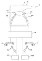
図1は、本発明の実施の形態にかかる医療機器システム2の概要を説明するための概要図である。図1において、表示手段である表示装置60の表示画面には、後述する内視鏡装置50の撮像手段であるCCD51が撮像した体内10の撮像画像61が表示されている。そして撮像画像61には、体内10の患部11の処置を行う2つの複数の関節を有するマニピュレータ100、200が表示されている。マニピュレータ100の先端部101にはハンドアームが配設されており、一方のマニピュレータ200の先端部201にはナイフアームが配設されている。
<Outline of medical device system>
FIG. 1 is a schematic diagram for explaining an outline of a
術者は、左右の手12、13で、それぞれマニピュレータ100、200の先端部101、201を現在の位置および姿勢から目標の位置および姿勢に移動する軌道を入力する軌道入力手段42である左右のマスタースレーブ装置42A、42Bを操作する。軌道入力手段42から入力された軌道情報に基づいて、マニピュレータ制御装置48はマニピュレータ100、200を駆動する。
The left and
なお、図1に示した医療機器システム2は、2つのマニピュレータを有するマニピュレータ装置を備える場合、1つのマニピュレータのみを有する場合、あるいは、3以上のマニピュレータを備える場合も本実施の形態と基本的な構成は同じである。
The
また、医療機器システム2は、マニピュレータは有する自由度から特定の自由度を選択し、非選択の自由度を制限する自由度選択手段43A、43Bを有する。本実施の形態のマニピュレータは複数の関節を有し、高い自由度を有しているが、医療機器システム2においては、処置によっては高い自由度のマニピュレータよりも低い自由度のマニピュレータの方が操作性が良く、より安全かつ確実に処理が行える場合がある。術者は処置に応じて自由度選択手段43A、43Bからマニピュレータ100、200の自由度を制限することが可能である。自由度選択手段43の動作については後に詳述する。
Further, the
なお、図1においては、軌道入力手段42としてマスタースレーブ型を示しているが、これに限定されるものではなく、所望の軌道が入力可能であれば、キーボードやタッチペンあるいは、ジョイスティツク等の公知の入力手段が使用可能である。 In FIG. 1, the master / slave type is shown as the trajectory input means 42, but the invention is not limited to this, and a keyboard, a touch pen, a joystick or the like can be used as long as a desired trajectory can be input. Known input means can be used.
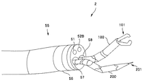
図2は、本実施の形態の医療機器システム2の外観を示した外観図である。図2において、2つのマニピュレータ100、200は、内視鏡55の先端部56の鉗子孔57、58から突出している。内視鏡先端部56には、撮像手段であるCCD51と、照明手段である照明部52Bも配設されている。また、図1と同様にマニピュレータ100の先端部101にはハンドアームが配設されており、一方のマニピュレータ200の先端部201にはナイフアームが配設されている。
FIG. 2 is an external view showing the external appearance of the
本実施の形態のマニピュレータは、内視鏡の先端部から突出させる超小型のマニピュレータであり、マニピュレータの直径は2〜5mm程度と極めて小さい。このため、公知の多くのマニピュレータとは異なり、効率的に駆動しなければ目的の処置を実行することが困難である。 The manipulator of the present embodiment is an ultra-small manipulator that protrudes from the distal end portion of the endoscope, and the manipulator has a very small diameter of about 2 to 5 mm. For this reason, unlike many known manipulators, it is difficult to execute a target treatment unless it is driven efficiently.
<マニピュレータの構造>
次に図3から図6を用いて本実施の形態のマニピュレータの構造を説明する。図3はマニピュレータ200の関節機能を説明するための図であり、図4はマニピュレータ200の外観斜視図であり、図5はマニピュレータ200の断面図であり、図6はマニピュレータ200の動作を説明するための断面図である。
<Manipulator structure>
Next, the structure of the manipulator of the present embodiment will be described with reference to FIGS. 3 is a view for explaining the joint function of the
図3(A)はマニピュレータ200の関節を示しており、マニピュレータ基端部210(座標:x0、y0、z0)から、直動駆動関節211(座標:x1、y1、z1)、回転駆動関節であるロール駆動関節212(座標:x2、y2、z2)、ヨー駆動関節213(座標:x3、y3、z3)、ピッチ駆動関節214(座標:x4、y4、z4)、ヨー駆動関節215(座標:x5、y5、z5)、ピッチ駆動関節216(座標:x6、y6、z6)の順で複数の関節があり、先端部201には、ナイフアームが配設されている。
FIG. 3A shows the joint of the
図3(B)はマニピュレータ200の関節を駆動した状態を示しており、ここでは、ヨー駆動関節213が−θ3だけ曲がり、ヨー駆動関節215がθ5だけ曲がっている。
FIG. 3B shows a state where the joint of the
マニピュレータ200は、これら複数の関節の関節角度を調整することで、先端部201を現在の位置および姿勢から目標の位置および姿勢に移動することができる。特に、マニピュレータ200は目標の位置および姿勢に移動するのに必要な自由度以上の自由度を有している、言い換えれば、作業上要求される自由度を超える自由度を有するため、目標の位置および姿勢に移動するための各関節の関節角軌道は複数存在する。このため、どのような関節角軌道を選択するかにより、マニピュレータ装置1の精度および効率が大きく変化する。
The
次に、図4から図5を用いてマニピュレータ200の構造を詳細に説明する。図4の斜視図に示すように、マニピュレータ200は、5つの関節コマ251〜255が4つの関節216〜219で連結されている。各関節はリベット260で2箇所が固定されているが、一方向に回転可能な構造を有している。すなわち、マニピュレータ200は2つのピッチ駆動関節216、214と2つのヨー駆動関節215、213を有している。各関節にはアングルワイヤ270の一端が対角線上に2箇所で固定されており、アングルワイヤ270を図示しない駆動手段23により操作することで、各関節を中心に関節コマ251〜255を曲げることができる。マニピュレータ200は、その先端部がナイフアーム201であり、マニピュレータ200を駆動することによりナイフアーム201の位置および姿勢が変化する。
Next, the structure of the
図5は、図4で示したマニピュレータ200の断面図である。マニピュレータ200の中心部には、絶縁性の可撓性管271の内部に配設された高周波電流を通電可能なナイフアームの操作ワイヤ272が配設され、操作ワイヤ272はナイフアーム201と電気的に接続されている。
FIG. 5 is a cross-sectional view of the
図6は、ナイフアーム201がマニピュレータ200内部に収納された状態で、ピッチ駆動関節216をアングルワイヤ(不図示)が引っ張り、最先端の湾曲コマ251を湾曲させた状態を示している。
FIG. 6 shows a state in which the
マニピュレータ装置1は、マニピュレータ200の駆動にアングルワイヤを用いているため構造が簡単で信頼性が高く、かつ小型化が可能となった。
Since the
<医療機器システムの構成>
次に図7を用い、本実施の形態の医療機器システム2の構成を説明する。図7は、本実施の形態の医療機器システム2の構成図である。なお、以下では、説明を簡単にするため、1つのマニピュレータ200を有する医療機器システム2について説明するが、複数のマニピュレータ装置1を有する医療機器システム2についても、それぞれのマニピュレータ装置1のための構成要素が追加されるだけであり、基本的な構成および動作は以下の説明と同様である。
<Configuration of medical device system>
Next, the configuration of the
図7は、体内10で駆動する駆動部20を有するマニピュレータ(不図示)を中心とした医療機器システム2の構成を示している。マニピュレータは、負荷センサ21、位置センサ22および駆動手段23を有している。
Figure 7 shows a configuration of a
負荷センサ21は、マニピュレータの各関節を駆動し、所望の動作を行った際に、生じるそれぞれの関節への負荷を検出するものである。負荷量は回転駆動関節の場合には発生したトルク(N/m)であり、直動駆動関節の場合には力(N)で表される。負荷検出の具体的方法としては、例えば、ワイヤ駆動の場合にはワイヤの張力を測定することで負荷が検出可能である。あるいは、ひずみゲージ等でも負荷は検出可能であるが、ワイヤをモータで駆動する場合にはモータの消費電力から検出できる。すなわち、必ずしもマニピュレータに新規にセンサを組み込む必要はなく、マニピュレータの構成要素をそのままセンサとして用い、負荷検出手段40に負荷情報を出力することも可能である。
The
位置センサ22は、それぞれの関節の位置および姿勢を検出するためのセンサであり、磁気センサ等を用いる。なお、位置センサ22は負荷センサ21と同様に必ずしもマニピュレータにセンサを組み込む必要はなく、駆動手段23による各関節の位置および姿勢の変化をエンコーダで検出し、位置算出手段41に位置情報を出力することも可能である。
The
軌道設定手段45は、位置算出手段41と軌道入力手段42と自由度選択手段43からの情報とパラメータ入力手段から入力されパラメータ記憶手段に記憶されている関節パラメータとを基に、それぞれの関節の関節角軌道を設定する。 The trajectory setting means 45 is based on the information from the position calculation means 41, trajectory input means 42 and degree-of-freedom selection means 43 and the joint parameters input from the parameter input means and stored in the parameter storage means. Set the joint angle trajectory.
駆動制御手段47は、軌道設定手段45が設定した関節角軌道に従ってマニピュレータの関節の駆動手段23を駆動する。 The drive control means 47 drives the joint drive means 23 of the manipulator according to the joint angle trajectory set by the trajectory setting means 45.
内視鏡装置50は、挿入部(不図示)先端部に配設されたCCD等の撮像手段51と、体内部を照明するための照明手段52と、撮像手段51が撮像した画像の処理等をする撮像制御部53と、内視鏡全体の制御を行う内視鏡制御部54とを有する。
The
また、内視鏡装置50の撮像画像を表示する表示装置60は、タッチパネルとしてマニピュレータの軌道入力等にも使用できる。
In addition, the
なお、複数の関節の全てについて負荷センサ21、負荷検出手段40、位置センサ22あるいは位置算出手段41等を有する必要はなく、特に、直動駆動関節211やロール駆動関節212は手動駆動としてもよい。
Note that it is not necessary to have the
<マニピュレータ装置の動作>
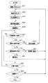
次に、図8のフローチャートを用いてマニピュレータ装置1の動作について説明する。図8は、マニピュレータ装置1の動作の流れを説明するためのフローチャートである。
<Operation of manipulator device>
Next, operation | movement of the
「ステップS11」
パラメータ入力手段44を用いて、各関節の関節パラメータを入力し、パラメータ記憶手段46に記憶する。関節パラメータの入力は予め入力しておけば毎回行う必要はない。
“Step S11”
Using the parameter input means 44, the joint parameters of each joint are input and stored in the parameter storage means 46. The joint parameters need not be input every time if they are input in advance.
関節パラメータとは、マニピュレータの各関節を駆動するために必要な関節の情報である。医療機器システム2においては、関節パラメータとして、DHパラメータ(初期座標、長さ、方向等)と、関節の可動範囲(角度範囲や直動範囲等)と、関節の動作精度(応答速度等)とを有する。さらに、医療機器システム2においては、関節パラメータとして関節の最大力量と、関節の負荷許容量とを有する。
The joint parameter is information on a joint necessary for driving each joint of the manipulator. In the
関節の最大力量とは、各関節が発生することのできる最大の力量であり、回転駆動関節ではトルク量(N/m)や駆動モータの電力値(W)で表現できる。また、関節の負荷許容量とは、各関節に加えることのできる最大の負荷であり、負荷許容量を超えた負荷が関節に加わると関節や駆動ワイヤの破損が生じるおそれのある負荷量であり、回転駆動関節では、やはりトルク量や駆動モータの電力値で表現できる。 The maximum amount of force of a joint is the maximum amount of force that can be generated by each joint, and can be expressed by a torque amount (N / m) or a power value (W) of a drive motor for a rotary drive joint. The joint load allowance is the maximum load that can be applied to each joint. If a load exceeding the load allowance is applied to the joint, the joint or the drive wire may be damaged. In the rotary drive joint, it can be expressed by the amount of torque and the power value of the drive motor.
なお、パラメータ記憶手段46に記憶する関節パラメータは、力量または負荷許容量の順に順位付けをしておくことでステップS12以降の軌道入力手段42の処理の高速化を図ることができる。 It should be noted that the joint parameters stored in the parameter storage means 46 are ranked in the order of the strength or the load allowable amount, so that the processing of the trajectory input means 42 after step S12 can be speeded up.
「ステップS12」
軌道入力手段42により、マニピュレータの先端を現在の位置および姿勢から目標の位置および姿勢に移動する軌道計画が入力される。
“Step S12”
The trajectory input means 42 inputs a trajectory plan for moving the tip of the manipulator from the current position and posture to the target position and posture.
「ステップS13」
自由度選択手段43により、マニピュレータの自由度を制限する情報が入力される。本実施の形態のマニピュレータは、3次元空間の任意の位置において任意の姿勢が可能な6自由度を有している。
"Step S13"
Information for limiting the degree of freedom of the manipulator is input by the degree of
図9は、内視鏡撮像画像61であり、マニピュレータ200の先端部201のメスを用いて患部11を切開する処置を示している。この場合には、先端部201は、矢印Aで示したように左方向に直線11Bに沿って移動し、先端部201Bの位置に移動することが望ましい。しかし、術者のマスタースレーブ装置(軌道入力手段42)の操作においては、術者が注意深く操作を行っても、本来は不要なピッチ方向やロール方向への移動を伴ってしまうことがある。
FIG. 9 is an
マニピュレータ装置1においては、上記の処置の際に、自由度選択手段43により、ピッチ方向およびロール方向への自由度を制限することができる。なお、先端部がメスアームの場合には、ロール方向の自由度は基本的に不要である。
In the
自由度選択手段43からの自由度制限情報は、後述の軌道設定手段において、制限された自由度方向への軌道入力手段の入力がキャンセルされる。入力がキャンセルされるとは、例えば、移動方向をベクトルで表現できる場合であれば、制限された方向のベクトル成分を除くことを意味する。
The degree-of-freedom restriction information from the degree-of-
そして、自由度選択手段43から自由度を制限することにより、マニピュレータ装置1は、より安全かつ確実に処理が行える。
Then, by limiting the degree of freedom from the degree of freedom selection means 43, the
「ステップS14」
軌道設定手段45は、関節パラメータおよび軌道計画に基づき、それぞれの関節の関節角軌道を設定する。軌道設定手段45は、パラメータ記憶手段46に記憶されたそれぞれの関節の最大力量を基に、目標の位置および姿勢に移動可能な最少の駆動関節数の関節角軌道のうち、最大力量の関節角軌道を設定する。なお、最大力量の関節角軌道を設定するとは、必ずしも最大力量を発生することの可能な関節を選択し関節角軌道を設定することではなく、力量の大きい関節(大きな力を発生させることの可能な関節)を優先的に選択し、最大力量を発生するような関節角軌道を設定するということである。
"Step S14"
The trajectory setting means 45 sets the joint angle trajectory of each joint based on the joint parameters and the trajectory plan. The
すなわち、本実施の形態のマニピュレータ装置1においては、逆問題計算により関節角軌道を設定する際に、動作精度を最優先とし、このため駆動関節数が最も少ない関節角軌道を設定する。そして、本実施の形態のマニピュレータ装置1は、動作精度の次に優先項目として、発生力量が大きい関節角軌道を設定する。
That is, in the
図10に、軌道設定手段45が設定した関節角軌道の例を示す。図10では、2つの回転駆動関節の関節角軌道を示している。 FIG. 10 shows an example of the joint angle trajectory set by the trajectory setting means 45. FIG. 10 shows joint angle trajectories of two rotary drive joints.
医療用の超小型のマニピュレータ装置1においては、精度は最も重要であり、かつ、超小型のため、マニピュレータの発生力量が小さく、所望の処置が実行出来ないことがあるからである。
In the
上記基準により軌道設定手段45が関節角軌道を設定するため、本実施の形態のマニピュレータ装置1は、より安全かつ確実に処理が行える。
Since the trajectory setting means 45 sets the joint angle trajectory based on the above reference, the
「ステップS15」
駆動制御手段47は、軌道設定手段45が設定した関節角軌道に従い、各関節の駆動手段23の駆動を開始する。
"Step S15"
The drive control means 47 starts driving the drive means 23 of each joint according to the joint angle trajectory set by the trajectory setting means 45.
「ステップS16」
各関節の駆動手段23の駆動が開始すると、各関節には負荷が発生する。特に、医療機器システム2のマニピュレータ装置1においては、処置する生体部位および個人差等により、その硬さや弾性等の物性値が大きく異なるために、処置を開始しないと関節にかかる負荷は予測が困難である。
"Step S16"
When driving of the driving means 23 of each joint is started, a load is generated at each joint. In particular, in the
このため、駆動手段23の駆動が開始すると、負荷検出手段40は負荷センサ21からの情報を基に、各関節の負荷量を算出する。そして、軌道設定手段45は、関節パラメータ記憶手段に記憶されている各関節の負荷許容量と各関節の負荷量の比較を行い、全ての関節の負荷量が負荷許容量未満である場合には、駆動手段23はマニピュレータ先端部が目標の位置および姿勢に移動するまで駆動を継続する。
For this reason, when the drive of the
これに対して、いずれかの関節の負荷量が負荷許容量以上である場合には、軌道設定手段45は、新たな関節角軌道を設定するため、以降の処理を行う。
On the other hand, when the load amount of any joint is equal to or greater than the allowable load amount, the
「ステップS17」
軌道設定手段45は、現在使用している関節よりも負荷許容量の大きい駆動していない関節がある場合(Yes)には、ステップS18において、駆動する関節を変更する。そして、再度、関節角軌道を算出する。
"Step S17"
The
現在使用している関節よりも負荷許容量の大きい駆動していない関節がない場合(No)には、ステップS19以降の処理を行う。 If there is no undriven joint having a larger load allowance than the currently used joint (No), the processes after step S19 are performed.
「ステップS19」
軌道設定手段45は、全ての関節を駆動していなかった場合(Yes)には、駆動する関節数をステップS20において1だけ増加する。そして、再度、関節角軌道を算出する。
"Step S19"
When all the joints are not driven (Yes), the
「ステップS21」
ステップS19において、軌道設定手段45は、全ての関節を駆動していた場合(No)には、入力された軌道に従いマニピュレータ先端部を目標の位置および姿勢に移動することは不可能であるため、警告手段70により警告を発生し、術者に知らせる。警告は、表示装置60への視覚による表示、音、振動等、公知の方法を用いることができる。
"Step S21"
In step S19, when all the joints are driven (No), the trajectory setting means 45 cannot move the manipulator tip to the target position and posture according to the input trajectory. A warning is generated by the warning means 70 to notify the operator. For the warning, a known method such as visual display on the
術者は、警告を受けて、再度、新たな軌道計画を入力することで処置が継続できる。 The surgeon receives the warning and can continue the treatment by inputting a new trajectory plan again.
「ステップS22およびS23」
マニピュレータ装置1は、マニピュレータ先端部が目標の位置および姿勢に移動するまで駆動制御手段47は、軌道設定手段45が設定した関節角軌道に従い、各関節の駆動手段23を駆動し、ステップS23における処置終了信号があるまで、マニピュレータ装置1は動作を続ける。
“Steps S22 and S23”
In the
本実施の形態のマニピュレータ装置1は、最少の駆動関節数で駆動するため精度が高く、かつ、超小型のマニピュレータであっても力量が大きいため、高精度かつ高効率性の駆動を確実に行うことができる。また、本実施の形態のマニピュレータ装置1を有する医療機器システム2は、高精度かつ高効率性の処置具の駆動を確実に行うことができる。
The
本発明は、上述した実施の形態に限定されるものではなく、本発明の要旨を変えない範囲において、種々の変更、改変等が可能である。 The present invention is not limited to the above-described embodiments, and various changes and modifications can be made without departing from the scope of the present invention.
1…マニピュレータ装置、2…医療機器システム、11…患部、20…駆動部、21…負荷センサ、22…位置センサ、23…駆動手段、40…負荷検出手段、41…位置算出手段、42、42A、42B…軌道入力手段、43、43A、43B…自由度選択手段、45…軌道設定手段、46…パラメータ記憶手段、47…駆動制御手段、48…マニピュレータ制御装置、50…内視鏡装置、51…CCD、52…照明部、53…撮像制御部、54…内視鏡制御部、55…内視鏡、56…先端部、60…表示装置、61…撮像画像、70…警告手段、100、200…マニピュレータ、101、201…マニピュレータ先端部、211…直動駆動関節、212…ロール駆動関節、212…回転駆動関節、213、215…ヨー駆動関節、214、216…ピッチ駆動関節
DESCRIPTION OF
Claims (5)
前記複数の関節の、それぞれの関節の関節パラメータを記憶するパラメータ記憶手段と、
前記マニピュレータの先端を現在の位置および姿勢から目標の位置および姿勢に移動する軌道を軌道計画として入力する軌道入力手段と、
前記関節パラメータおよび前記軌道計画に基づき、前記それぞれの関節の関節角軌道を設定する軌道設定手段と、を有し、
前記軌道設定手段は、前記パラメータ記憶手段に記憶された前記それぞれの関節の最大力量を基に、前記目標の位置および姿勢に移動可能な最少の駆動関節数の関節角軌道のうち、前記最大力量の大きい関節が優先的に選択され、発生力量が最も大きい関節角軌道を設定することを特徴とするマニピュレータ装置。 A manipulator having a plurality of joints;
Parameter storage means for storing joint parameters of each of the plurality of joints;
A trajectory input means for inputting a trajectory for moving the tip of the manipulator from a current position and posture to a target position and posture as a trajectory plan;
Trajectory setting means for setting a joint angle trajectory of each joint based on the joint parameters and the trajectory plan,
The trajectory setting means, wherein based on the maximum force of each stored the joints in the parameter storage unit, among the joint angle trajectories of the number of drive joints minimum movable to a position and orientation of the target, the maximum force A manipulator apparatus characterized by preferentially selecting a joint having a large and setting a joint angle trajectory having the largest generated force .
前記軌道設定手段は、前記パラメータ記憶手段に記憶された前記それぞれの関節の負荷許容量を基に、前記それぞれの関節の前記負荷量が、負荷許容量を超えることのない関節角軌道を設定することを特徴とする請求項1に記載のマニピュレータ装置。 Load detecting means for detecting the load amount of each joint;
The trajectory setting means sets a joint angle trajectory in which the load amount of each joint does not exceed the allowable load amount based on the allowable load amount of each joint stored in the parameter storage means. The manipulator device according to claim 1.
前記軌道設定手段は、制限された自由度方向への前記軌道入力手段の入力をキャンセルすることを特徴とする請求項1または請求項2に記載のマニピュレータ装置。 2. The degree-of-freedom selecting means for selecting the degree of freedom of the manipulator, wherein the trajectory setting means cancels the input of the trajectory input means in the restricted degree of freedom direction. The manipulator device according to claim 2.
Priority Applications (4)
| Application Number | Priority Date | Filing Date | Title |
|---|---|---|---|
| JP2007282144A JP5028219B2 (en) | 2007-10-30 | 2007-10-30 | Manipulator device and medical device system |
| CN2008101749426A CN101422901B (en) | 2007-10-30 | 2008-10-24 | Manipulator apparatus and medical device system |
| EP08018811.3A EP2058090B1 (en) | 2007-10-30 | 2008-10-28 | Manipulator apparatus and medical device system |
| US12/260,437 US8388605B2 (en) | 2007-10-30 | 2008-10-29 | Manipulator apparatus and medical device system |
Applications Claiming Priority (1)
| Application Number | Priority Date | Filing Date | Title |
|---|---|---|---|
| JP2007282144A JP5028219B2 (en) | 2007-10-30 | 2007-10-30 | Manipulator device and medical device system |
Publications (3)
| Publication Number | Publication Date |
|---|---|
| JP2009107074A JP2009107074A (en) | 2009-05-21 |
| JP2009107074A5 JP2009107074A5 (en) | 2009-12-24 |
| JP5028219B2 true JP5028219B2 (en) | 2012-09-19 |
Family
ID=40473663
Family Applications (1)
| Application Number | Title | Priority Date | Filing Date |
|---|---|---|---|
| JP2007282144A Active JP5028219B2 (en) | 2007-10-30 | 2007-10-30 | Manipulator device and medical device system |
Country Status (4)
| Country | Link |
|---|---|
| US (1) | US8388605B2 (en) |
| EP (1) | EP2058090B1 (en) |
| JP (1) | JP5028219B2 (en) |
| CN (1) | CN101422901B (en) |
Families Citing this family (51)
| Publication number | Priority date | Publication date | Assignee | Title |
|---|---|---|---|---|
| JP5509673B2 (en) * | 2009-05-22 | 2014-06-04 | 株式会社Ihi | Robot control apparatus and control method thereof |
| WO2011043234A1 (en) * | 2009-10-09 | 2011-04-14 | オリンパスメディカルシステムズ株式会社 | Endoscope device |
| CN102236336B (en) * | 2010-04-26 | 2013-08-28 | 鸿富锦精密工业(深圳)有限公司 | Motion control system and method |
| US20130190774A1 (en) | 2010-08-11 | 2013-07-25 | Ecole Polytechnique Ferderale De Lausanne (Epfl) | Mechanical positioning system for surgical instruments |
| JP5612971B2 (en) * | 2010-09-07 | 2014-10-22 | オリンパス株式会社 | Master-slave manipulator |
| EP2627278B1 (en) | 2010-10-11 | 2015-03-25 | Ecole Polytechnique Fédérale de Lausanne (EPFL) | Mechanical manipulator for surgical instruments |
| EP2645943A1 (en) | 2010-12-02 | 2013-10-09 | Agile Endosurgery, Inc. | Surgical tool |
| US9921712B2 (en) | 2010-12-29 | 2018-03-20 | Mako Surgical Corp. | System and method for providing substantially stable control of a surgical tool |
| US9119655B2 (en) | 2012-08-03 | 2015-09-01 | Stryker Corporation | Surgical manipulator capable of controlling a surgical instrument in multiple modes |
| CN102528802B (en) * | 2010-12-31 | 2014-12-03 | 北京中科广视科技有限公司 | Motion driving method for robot with nine degrees of freedom |
| JP5796982B2 (en) * | 2011-03-31 | 2015-10-21 | オリンパス株式会社 | SURGERY SYSTEM CONTROL DEVICE AND CONTROL METHOD |
| JP5715304B2 (en) | 2011-07-27 | 2015-05-07 | エコール ポリテクニーク フェデラル デ ローザンヌ (イーピーエフエル) | Mechanical remote control device for remote control |
| JP6141289B2 (en) * | 2011-10-21 | 2017-06-07 | インテュイティブ サージカル オペレーションズ, インコーポレイテッド | Gripping force control for robotic surgical instrument end effector |
| KR101289785B1 (en) * | 2011-12-28 | 2013-07-26 | 한국과학기술원 | System for generating optimal trajectory of robot manipulator that minimized the joint torque variation and method therefor |
| JP5938954B2 (en) * | 2012-03-06 | 2016-06-22 | 株式会社ジェイテクト | Robot calibration method and calibration apparatus |
| JP6083076B2 (en) * | 2012-04-04 | 2017-02-22 | 大平 猛 | Motion memory type small diameter surgical robot system |
| US9226796B2 (en) | 2012-08-03 | 2016-01-05 | Stryker Corporation | Method for detecting a disturbance as an energy applicator of a surgical instrument traverses a cutting path |
| US9820818B2 (en) | 2012-08-03 | 2017-11-21 | Stryker Corporation | System and method for controlling a surgical manipulator based on implant parameters |
| AU2013296278B2 (en) | 2012-08-03 | 2018-06-14 | Stryker Corporation | Systems and methods for robotic surgery |
| JP6010225B2 (en) * | 2013-06-13 | 2016-10-19 | テルモ株式会社 | Medical manipulator |
| US10687909B2 (en) | 2014-01-24 | 2020-06-23 | Koninklijke Philips N.V. | Robotic control of imaging devices with optical shape sensing |
| JP6220085B2 (en) | 2014-02-03 | 2017-10-25 | ディスタルモーション エスエーDistalmotion Sa | Mechanical remote control device with replaceable distal device |
| JP6270537B2 (en) | 2014-02-27 | 2018-01-31 | オリンパス株式会社 | Medical system |
| CN111904600A (en) * | 2014-05-05 | 2020-11-10 | 维卡瑞斯外科手术股份有限公司 | Virtual reality surgical device |
| JP6169049B2 (en) | 2014-06-19 | 2017-07-26 | オリンパス株式会社 | Manipulator control method, manipulator, and manipulator system |
| WO2016030767A1 (en) | 2014-08-27 | 2016-03-03 | Distalmotion Sa | Surgical system for microsurgical techniques |
| JP6416560B2 (en) | 2014-09-11 | 2018-10-31 | 株式会社デンソー | Positioning control device |
| EP3232952B1 (en) | 2014-12-19 | 2020-02-19 | DistalMotion SA | Reusable surgical instrument for minimally invasive procedures |
| US10548680B2 (en) | 2014-12-19 | 2020-02-04 | Distalmotion Sa | Articulated handle for mechanical telemanipulator |
| US10864052B2 (en) | 2014-12-19 | 2020-12-15 | Distalmotion Sa | Surgical instrument with articulated end-effector |
| US10864049B2 (en) | 2014-12-19 | 2020-12-15 | Distalmotion Sa | Docking system for mechanical telemanipulator |
| EP3232973B1 (en) | 2014-12-19 | 2020-04-01 | DistalMotion SA | Sterile interface for articulated surgical instruments |
| WO2016161444A1 (en) * | 2015-04-03 | 2016-10-06 | Think Surgical, Inc. | Robotic system with intuitive motion control |
| US10568709B2 (en) | 2015-04-09 | 2020-02-25 | Distalmotion Sa | Mechanical teleoperated device for remote manipulation |
| EP3280337B1 (en) | 2015-04-09 | 2019-11-13 | DistalMotion SA | Articulated hand-held instrument |
| WO2016199228A1 (en) * | 2015-06-09 | 2016-12-15 | オリンパス株式会社 | Medical manipulator control device |
| DE102015009048B3 (en) * | 2015-07-13 | 2016-08-18 | Kuka Roboter Gmbh | Controlling a compliant controlled robot |
| EP3340897A1 (en) | 2015-08-28 | 2018-07-04 | DistalMotion SA | Surgical instrument with increased actuation force |
| WO2018059838A1 (en) * | 2016-09-27 | 2018-04-05 | Brainlab Ag | Efficient positioning of a mechatronic arm |
| WO2018112025A1 (en) | 2016-12-16 | 2018-06-21 | Mako Surgical Corp. | Techniques for modifying tool operation in a surgical robotic system based on comparing actual and commanded states of the tool relative to a surgical site |
| CN106667534A (en) * | 2017-01-07 | 2017-05-17 | 吕海 | Minimally invasive surgery system used for excising lesion lumbar interverbral tissues causing lumbar intervertebral disc herniation |
| US11058503B2 (en) | 2017-05-11 | 2021-07-13 | Distalmotion Sa | Translational instrument interface for surgical robot and surgical robot systems comprising the same |
| JP7005773B2 (en) * | 2018-01-04 | 2022-01-24 | コヴィディエン リミテッド パートナーシップ | Robotic surgical instruments including high range of motion wrist assembly with torque transmission and mechanical manipulation |
| JP7064190B2 (en) * | 2018-01-23 | 2022-05-10 | 国立大学法人東海国立大学機構 | Surgical instrument control device and surgical instrument control method |
| EP3749243A1 (en) | 2018-02-07 | 2020-12-16 | Distalmotion SA | Surgical robot systems comprising robotic telemanipulators and integrated laparoscopy |
| CN109551478A (en) * | 2018-11-16 | 2019-04-02 | 重庆邮电大学 | A kind of dual robot principal and subordinate's control method for coordinating based on Distributed Control System |
| CN110251277B (en) * | 2019-05-29 | 2022-02-08 | 广东工业大学 | Method for manufacturing personalized acetabulum prosthesis and auxiliary method for total hip replacement |
| US11771507B2 (en) * | 2019-08-21 | 2023-10-03 | Cilag Gmbh International | Articulable wrist with flexible member and pivot guides |
| CN111887906B (en) * | 2019-09-10 | 2021-05-11 | 深圳市精锋医疗科技有限公司 | Surgical robot and control method and control device for mechanical arm of surgical robot |
| KR102616257B1 (en) * | 2021-10-18 | 2023-12-22 | 주식회사 로엔서지컬 | Hysteresis compensation apparatus of flexible tube and method thereof |
| US11844585B1 (en) | 2023-02-10 | 2023-12-19 | Distalmotion Sa | Surgical robotics systems and devices having a sterile restart, and methods thereof |
Family Cites Families (21)
| Publication number | Priority date | Publication date | Assignee | Title |
|---|---|---|---|---|
| JPS59175987A (en) * | 1983-03-26 | 1984-10-05 | 株式会社東芝 | Multi-joint robot device |
| JPS626306A (en) * | 1985-07-03 | 1987-01-13 | Hitachi Ltd | Control method for articulated arm |
| JPS62232006A (en) * | 1986-04-02 | 1987-10-12 | Yokogawa Electric Corp | Robot system |
| US4835710A (en) * | 1987-07-17 | 1989-05-30 | Cincinnati Milacron Inc. | Method of moving and orienting a tool along a curved path |
| JP2698660B2 (en) * | 1989-06-12 | 1998-01-19 | 株式会社日立製作所 | Manipulator control method and control device, and manipulator device |
| JP3012709B2 (en) * | 1991-08-07 | 2000-02-28 | 株式会社リコー | Facsimile machine |
| US5515478A (en) * | 1992-08-10 | 1996-05-07 | Computer Motion, Inc. | Automated endoscope system for optimal positioning |
| JPH06342121A (en) | 1993-04-06 | 1994-12-13 | Olympus Optical Co Ltd | Micromanipulator |
| JP3717552B2 (en) | 1995-09-01 | 2005-11-16 | オリンパス株式会社 | Medical manipulator system |
| SE505981C2 (en) * | 1996-02-14 | 1997-10-27 | Asea Brown Boveri | Procedure for controlling an industrial robot with regard to torque and load |
| US6493608B1 (en) * | 1999-04-07 | 2002-12-10 | Intuitive Surgical, Inc. | Aspects of a control system of a minimally invasive surgical apparatus |
| JP4422257B2 (en) * | 1999-11-24 | 2010-02-24 | オリンパス株式会社 | Manipulator control device |
| DE60226410D1 (en) * | 2001-01-29 | 2008-06-19 | Acrobot Co Ltd | ROBOT WITH ACTIVE RESTRICTIONS |
| AU2003257309A1 (en) * | 2002-08-13 | 2004-02-25 | Microbotics Corporation | Microsurgical robot system |
| JP3934524B2 (en) * | 2002-10-09 | 2007-06-20 | 株式会社日立製作所 | Surgical manipulator |
| US7930065B2 (en) * | 2005-12-30 | 2011-04-19 | Intuitive Surgical Operations, Inc. | Robotic surgery system including position sensors using fiber bragg gratings |
| EP1815949A1 (en) * | 2006-02-03 | 2007-08-08 | The European Atomic Energy Community (EURATOM), represented by the European Commission | Medical robotic system with manipulator arm of the cylindrical coordinate type |
| EP1815950A1 (en) * | 2006-02-03 | 2007-08-08 | The European Atomic Energy Community (EURATOM), represented by the European Commission | Robotic surgical system for performing minimally invasive medical procedures |
| US9549663B2 (en) * | 2006-06-13 | 2017-01-24 | Intuitive Surgical Operations, Inc. | Teleoperated surgical retractor system |
| WO2007149559A2 (en) * | 2006-06-22 | 2007-12-27 | Board Of Regents Of The University Of Nebraska | Magnetically coupleable robotic devices and related methods |
| JP4891823B2 (en) * | 2007-03-29 | 2012-03-07 | オリンパスメディカルシステムズ株式会社 | Endoscope device |
-
2007
- 2007-10-30 JP JP2007282144A patent/JP5028219B2/en active Active
-
2008
- 2008-10-24 CN CN2008101749426A patent/CN101422901B/en active Active
- 2008-10-28 EP EP08018811.3A patent/EP2058090B1/en active Active
- 2008-10-29 US US12/260,437 patent/US8388605B2/en active Active
Also Published As
| Publication number | Publication date |
|---|---|
| CN101422901B (en) | 2011-12-14 |
| EP2058090A2 (en) | 2009-05-13 |
| CN101422901A (en) | 2009-05-06 |
| US20090112316A1 (en) | 2009-04-30 |
| EP2058090A3 (en) | 2017-09-06 |
| JP2009107074A (en) | 2009-05-21 |
| US8388605B2 (en) | 2013-03-05 |
| EP2058090B1 (en) | 2019-01-02 |
Similar Documents
| Publication | Publication Date | Title |
|---|---|---|
| JP5028219B2 (en) | Manipulator device and medical device system | |
| JP6538360B2 (en) | Master device for surgical robot and control method thereof | |
| US11717309B2 (en) | Medical manipulator and method of controlling the same | |
| CN107921623B (en) | Robot system | |
| US20200315721A1 (en) | Computer-assisted tele-operated surgery systems and methods | |
| JP6117922B2 (en) | Medical manipulator and method of operating the same | |
| JP5669590B2 (en) | Master-slave manipulator and medical master-slave manipulator | |
| US20140142592A1 (en) | Surgical robot and surgical robot control method | |
| JPH07328016A (en) | Surgical manipulator system | |
| Wortman et al. | Single-site colectomy with miniature in vivo robotic platform | |
| JP6739544B2 (en) | Medical system and control method | |
| US20200214779A1 (en) | Control device, control method, and master-slave system | |
| CN116056655A (en) | Controlling an endoscope by a surgical robot | |
| Low et al. | A review of master–slave robotic systems for surgery | |
| JP6097390B2 (en) | Medical manipulator | |
| Evangeliou et al. | Development of an sma-actuated redundant robotic platform for minimally invasive surgery | |
| JP4346615B2 (en) | Medical manipulator | |
| JP2020065910A (en) | Surgery assistance apparatus | |
| US11926062B2 (en) | Methods and apparatus for controlling a continuum robot | |
| US20220401088A1 (en) | Method for controlling an articulating instrument | |
| Miayazaki et al. | Pneumatically-driven hand-held forceps with wrist joint operated by built-in master controller | |
| JP2001137257A (en) | Medical master-slave system | |
| Kam et al. | Minimally invasive surgery instruments based on a four-bar linkage design | |
| WO2017114860A1 (en) | Decoupled spatial positioning and orienting control of a remote-center-of-motion |
Legal Events
| Date | Code | Title | Description |
|---|---|---|---|
| A521 | Request for written amendment filed |
Free format text: JAPANESE INTERMEDIATE CODE: A523 Effective date: 20091105 |
|
| A621 | Written request for application examination |
Free format text: JAPANESE INTERMEDIATE CODE: A621 Effective date: 20091105 |
|
| A131 | Notification of reasons for refusal |
Free format text: JAPANESE INTERMEDIATE CODE: A131 Effective date: 20111227 |
|
| A521 | Request for written amendment filed |
Free format text: JAPANESE INTERMEDIATE CODE: A523 Effective date: 20120131 |
|
| TRDD | Decision of grant or rejection written | ||
| A01 | Written decision to grant a patent or to grant a registration (utility model) |
Free format text: JAPANESE INTERMEDIATE CODE: A01 Effective date: 20120605 |
|
| A01 | Written decision to grant a patent or to grant a registration (utility model) |
Free format text: JAPANESE INTERMEDIATE CODE: A01 |
|
| A61 | First payment of annual fees (during grant procedure) |
Free format text: JAPANESE INTERMEDIATE CODE: A61 Effective date: 20120625 |
|
| FPAY | Renewal fee payment (event date is renewal date of database) |
Free format text: PAYMENT UNTIL: 20150629 Year of fee payment: 3 |
|
| R151 | Written notification of patent or utility model registration |
Ref document number: 5028219 Country of ref document: JP Free format text: JAPANESE INTERMEDIATE CODE: R151 |
|
| S111 | Request for change of ownership or part of ownership |
Free format text: JAPANESE INTERMEDIATE CODE: R313111 |
|
| R350 | Written notification of registration of transfer |
Free format text: JAPANESE INTERMEDIATE CODE: R350 |
|
| S531 | Written request for registration of change of domicile |
Free format text: JAPANESE INTERMEDIATE CODE: R313531 |
|
| R350 | Written notification of registration of transfer |
Free format text: JAPANESE INTERMEDIATE CODE: R350 |
|
| R250 | Receipt of annual fees |
Free format text: JAPANESE INTERMEDIATE CODE: R250 |
|
| R250 | Receipt of annual fees |
Free format text: JAPANESE INTERMEDIATE CODE: R250 |
|
| R250 | Receipt of annual fees |
Free format text: JAPANESE INTERMEDIATE CODE: R250 |
|
| R250 | Receipt of annual fees |
Free format text: JAPANESE INTERMEDIATE CODE: R250 |
|
| R250 | Receipt of annual fees |
Free format text: JAPANESE INTERMEDIATE CODE: R250 |