EP3925563A1 - Device for robotic surgery - Google Patents
Device for robotic surgery Download PDFInfo
- Publication number
- EP3925563A1 EP3925563A1 EP21178931.8A EP21178931A EP3925563A1 EP 3925563 A1 EP3925563 A1 EP 3925563A1 EP 21178931 A EP21178931 A EP 21178931A EP 3925563 A1 EP3925563 A1 EP 3925563A1
- Authority
- EP
- European Patent Office
- Prior art keywords
- drive element
- rotation
- instrument
- sterile
- unit
- Prior art date
- Legal status (The legal status is an assumption and is not a legal conclusion. Google has not performed a legal analysis and makes no representation as to the accuracy of the status listed.)
- Pending
Links
Images


Classifications
-
- A—HUMAN NECESSITIES
- A61—MEDICAL OR VETERINARY SCIENCE; HYGIENE
- A61B—DIAGNOSIS; SURGERY; IDENTIFICATION
- A61B34/00—Computer-aided surgery; Manipulators or robots specially adapted for use in surgery
- A61B34/30—Surgical robots
- A61B34/37—Master-slave robots
-
- A—HUMAN NECESSITIES
- A61—MEDICAL OR VETERINARY SCIENCE; HYGIENE
- A61B—DIAGNOSIS; SURGERY; IDENTIFICATION
- A61B34/00—Computer-aided surgery; Manipulators or robots specially adapted for use in surgery
- A61B34/30—Surgical robots
-
- A—HUMAN NECESSITIES
- A61—MEDICAL OR VETERINARY SCIENCE; HYGIENE
- A61B—DIAGNOSIS; SURGERY; IDENTIFICATION
- A61B1/00—Instruments for performing medical examinations of the interior of cavities or tubes of the body by visual or photographical inspection, e.g. endoscopes; Illuminating arrangements therefor
- A61B1/00002—Operational features of endoscopes
- A61B1/00039—Operational features of endoscopes provided with input arrangements for the user
- A61B1/00042—Operational features of endoscopes provided with input arrangements for the user for mechanical operation
-
- A—HUMAN NECESSITIES
- A61—MEDICAL OR VETERINARY SCIENCE; HYGIENE
- A61B—DIAGNOSIS; SURGERY; IDENTIFICATION
- A61B1/00—Instruments for performing medical examinations of the interior of cavities or tubes of the body by visual or photographical inspection, e.g. endoscopes; Illuminating arrangements therefor
- A61B1/00147—Holding or positioning arrangements
- A61B1/0016—Holding or positioning arrangements using motor drive units
-
- A—HUMAN NECESSITIES
- A61—MEDICAL OR VETERINARY SCIENCE; HYGIENE
- A61B—DIAGNOSIS; SURGERY; IDENTIFICATION
- A61B17/00—Surgical instruments, devices or methods, e.g. tourniquets
- A61B17/28—Surgical forceps
- A61B17/29—Forceps for use in minimally invasive surgery
-
- A—HUMAN NECESSITIES
- A61—MEDICAL OR VETERINARY SCIENCE; HYGIENE
- A61B—DIAGNOSIS; SURGERY; IDENTIFICATION
- A61B34/00—Computer-aided surgery; Manipulators or robots specially adapted for use in surgery
- A61B34/70—Manipulators specially adapted for use in surgery
- A61B34/73—Manipulators for magnetic surgery
-
- A—HUMAN NECESSITIES
- A61—MEDICAL OR VETERINARY SCIENCE; HYGIENE
- A61B—DIAGNOSIS; SURGERY; IDENTIFICATION
- A61B50/00—Containers, covers, furniture or holders specially adapted for surgical or diagnostic appliances or instruments, e.g. sterile covers
-
- A—HUMAN NECESSITIES
- A61—MEDICAL OR VETERINARY SCIENCE; HYGIENE
- A61B—DIAGNOSIS; SURGERY; IDENTIFICATION
- A61B90/00—Instruments, implements or accessories specially adapted for surgery or diagnosis and not covered by any of the groups A61B1/00 - A61B50/00, e.g. for luxation treatment or for protecting wound edges
- A61B90/36—Image-producing devices or illumination devices not otherwise provided for
- A61B90/361—Image-producing devices, e.g. surgical cameras
-
- A—HUMAN NECESSITIES
- A61—MEDICAL OR VETERINARY SCIENCE; HYGIENE
- A61B—DIAGNOSIS; SURGERY; IDENTIFICATION
- A61B90/00—Instruments, implements or accessories specially adapted for surgery or diagnosis and not covered by any of the groups A61B1/00 - A61B50/00, e.g. for luxation treatment or for protecting wound edges
- A61B90/90—Identification means for patients or instruments, e.g. tags
- A61B90/98—Identification means for patients or instruments, e.g. tags using electromagnetic means, e.g. transponders
-
- B—PERFORMING OPERATIONS; TRANSPORTING
- B25—HAND TOOLS; PORTABLE POWER-DRIVEN TOOLS; MANIPULATORS
- B25J—MANIPULATORS; CHAMBERS PROVIDED WITH MANIPULATION DEVICES
- B25J13/00—Controls for manipulators
- B25J13/08—Controls for manipulators by means of sensing devices, e.g. viewing or touching devices
- B25J13/088—Controls for manipulators by means of sensing devices, e.g. viewing or touching devices with position, velocity or acceleration sensors
-
- B—PERFORMING OPERATIONS; TRANSPORTING
- B25—HAND TOOLS; PORTABLE POWER-DRIVEN TOOLS; MANIPULATORS
- B25J—MANIPULATORS; CHAMBERS PROVIDED WITH MANIPULATION DEVICES
- B25J19/00—Accessories fitted to manipulators, e.g. for monitoring, for viewing; Safety devices combined with or specially adapted for use in connection with manipulators
- B25J19/0025—Means for supplying energy to the end effector
- B25J19/0045—Contactless power transmission, e.g. by magnetic induction
-
- A—HUMAN NECESSITIES
- A61—MEDICAL OR VETERINARY SCIENCE; HYGIENE
- A61B—DIAGNOSIS; SURGERY; IDENTIFICATION
- A61B17/00—Surgical instruments, devices or methods, e.g. tourniquets
- A61B2017/00477—Coupling
-
- A—HUMAN NECESSITIES
- A61—MEDICAL OR VETERINARY SCIENCE; HYGIENE
- A61B—DIAGNOSIS; SURGERY; IDENTIFICATION
- A61B17/00—Surgical instruments, devices or methods, e.g. tourniquets
- A61B2017/00831—Material properties
- A61B2017/00876—Material properties magnetic
-
- A—HUMAN NECESSITIES
- A61—MEDICAL OR VETERINARY SCIENCE; HYGIENE
- A61B—DIAGNOSIS; SURGERY; IDENTIFICATION
- A61B34/00—Computer-aided surgery; Manipulators or robots specially adapted for use in surgery
- A61B34/30—Surgical robots
- A61B2034/301—Surgical robots for introducing or steering flexible instruments inserted into the body, e.g. catheters or endoscopes
-
- A—HUMAN NECESSITIES
- A61—MEDICAL OR VETERINARY SCIENCE; HYGIENE
- A61B—DIAGNOSIS; SURGERY; IDENTIFICATION
- A61B34/00—Computer-aided surgery; Manipulators or robots specially adapted for use in surgery
- A61B34/30—Surgical robots
- A61B2034/302—Surgical robots specifically adapted for manipulations within body cavities, e.g. within abdominal or thoracic cavities
-
- A—HUMAN NECESSITIES
- A61—MEDICAL OR VETERINARY SCIENCE; HYGIENE
- A61B—DIAGNOSIS; SURGERY; IDENTIFICATION
- A61B34/00—Computer-aided surgery; Manipulators or robots specially adapted for use in surgery
- A61B34/30—Surgical robots
- A61B2034/305—Details of wrist mechanisms at distal ends of robotic arms
-
- A—HUMAN NECESSITIES
- A61—MEDICAL OR VETERINARY SCIENCE; HYGIENE
- A61B—DIAGNOSIS; SURGERY; IDENTIFICATION
- A61B90/00—Instruments, implements or accessories specially adapted for surgery or diagnosis and not covered by any of the groups A61B1/00 - A61B50/00, e.g. for luxation treatment or for protecting wound edges
- A61B90/06—Measuring instruments not otherwise provided for
- A61B2090/067—Measuring instruments not otherwise provided for for measuring angles
-
- A—HUMAN NECESSITIES
- A61—MEDICAL OR VETERINARY SCIENCE; HYGIENE
- A61B—DIAGNOSIS; SURGERY; IDENTIFICATION
- A61B46/00—Surgical drapes
- A61B46/10—Surgical drapes specially adapted for instruments, e.g. microscopes
Definitions
- the invention relates to a device for robot-assisted surgery with at least one manipulator arm with a non-sterile coupling unit which has at least one first drive element.
- the device furthermore has at least one sterile instrument unit which is arranged in a sterile area and which comprises at least one second drive element which is arranged so as to be rotatable about an axis of rotation.
- the instrument unit can be coupled to the coupling unit.
- telemanipulator systems which are also referred to as robot assistance systems, are increasingly being used for robot-assisted surgery.
- the sterile operating field is protected from the non-sterile elements of the telemanipulator system with the aid of a sterile cover.
- the sterile cover prevents both contamination of the sterile operating field and contamination of the telemanipulator system by body fluids and / or tissue of the operated patient or the operating staff. This reduces the risk of cross-contamination.
- a coupling interface which can be designed as a coupling unit, is provided on each manipulator arm.
- a sterile interface and / or a sterile barrier is required to prevent contamination of the devices of category 1 or category 2 by the non-sterile devices of the category 3 prevents and, conversely, prevents contamination of the category 3 devices, since these are generally technically designed as non-sterilizable and non-autoclavable components.
- the design of devices as sterilizable and autoclavable components requires a special technical design of the device for the sterilization process, so that this requires a higher development effort as well as a considerable validation effort to prove the effectiveness of the Sterilization process are required.
- a telemanipulator system in which the non-sterile manipulator arms are covered by means of a sterile film.
- the coupling unit of the manipulator arm comprises four rotation actuators, which are coupled to a first side of a sterile adapter integrated in the sterile film.
- the rotary movements of the four rotary actuators of the coupling unit of the manipulator arm are coupled in engagement with four rotatably mounted transmission means that are integrated in the sterile adapter.
- these sterile transmission means can be brought into engagement with driven elements of the sterile surgical instrument.
- electrical signals can be transmitted between the inside and the outside of the sterile adapter via this sterile adapter.
- the sterile adapter thus prevents the rotation actuators and the electrical connections of the sterile surgical instrument from coming into direct contact with the rotation actuators and the electrical connections of the coupling unit of the non-sterile manipulator arm. Contamination of the surgical instrument through contact with non-sterile parts of the manipulator arm is prevented by the sterile adapter.
- the sterile adapter it is necessary that the sterile adapter must have rotatably mounted transmission means and transmission means for the transmission of electrical signals, whereby the adapter is expensive to manufacture and prone to failure.
- the sterile adapter itself is intended as part of the sterile foil for single use.
- a sterile lock which sterile shields drive elements of a coupling unit from a sterile operating area before a sterile instrument unit is connected to the sterile lock and after the sterile instrument unit is separated from the sterile lock.
- the sterile instrument unit has sterile flaps which sterile shields the drive element of the instrument unit from a sterile operating area before the sterile instrument unit is connected to the sterile lock and after the sterile instrument unit is separated from the sterile lock.
- every element in the functional chain for coupling the manipulator arm and the instrument is a possible source of error and is associated with additional costs.
- the known sterile locks and sterile adapters have bearings and / or abutment surfaces for flaps, the impermeability of which must be ensured.
- the object of the invention is to provide a device for robot-assisted surgery in which a sterile coupling of a coupling unit of a non-sterile manipulator arm with a sterile instrument unit arranged in a sterile area is easily possible, a reliable force transmission between the coupling unit and the instrument unit being possible and a sterile barrier shields non-sterile items from the sterile area.
- a device for robot-assisted surgery comprises at least one manipulator arm with a non-sterile coupling unit which comprises at least one first drive element. Furthermore, the device comprises a sterile instrument unit which is arranged in a sterile area and which comprises at least one second drive element which is arranged rotatably about an axis of rotation, the instrument unit with the Coupling unit of the manipulator arm can be coupled.
- the first drive element and the second drive element are designed and arranged in a coupled state in such a way that the first drive element can exert a force on the second drive element to rotate the second drive element about the axis of rotation.
- the device comprises a sterile barrier which is arranged at least between the first drive element and the second drive element.
- the first drive element can also be referred to as a coupling unit drive element and the second drive element as an instrument drive element.
- the first drive element is arranged in the plane of rotation of the second drive element in such a way that a surface of the first drive element facing the second drive element runs in at least one area parallel to a cylindrical jacket surface or a cylindrical jacket jacket surface of the second drive element.
- magnetic field-generating elements are arranged in the plane of rotation on a side of the first drive element facing the second drive element and magnetic field-generating or magnetic elements of the second drive element are arranged on a circular path around the axis of rotation. This enables a particularly reliable drive of the second drive element.
- the magnetic field generating elements of the first drive element are electromagnets and the magnetic field generating elements of the second drive element are electromagnets with circumferential alternating poles, or if the magnetic field generating elements of the first drive element are electromagnets and the magnetic elements of the second drive element are permanent magnets with alternating poles all around. This enables a particularly compact and robust design.
- magnetic fields can be generated in the first drive element with the aid of the electromagnets, through which the force can be exerted on the permanent magnets of the second drive element, the second drive element rotating by changing the polarity of the electromagnets and / or changing a switching state of the electromagnets . This enables a reliable drive of the second drive element.
- the first drive element comprises at least one movable and / or deformable actuator which is movable and / or deformable in such a way that the actuator makes contact with a lateral surface of the second drive element at least temporarily in such a way that a force fit and / or form fit between the actuator and the lateral surface of the second drive element, the force can be exerted on the second drive element.
- a particularly reliable power transmission from the first to the second drive element is achieved.
- the actuator is at least one piezoelectric actuator and with which the force can be exerted on the second drive element through a force fit and / or form fit between the actuator and the outer surface of the second drive element. This achieves a particularly powerful drive for the second drive element.
- the surface of the first drive element facing the second drive element runs along an arc around the axis of rotation with a central angle of 45 ° to 180 °. This ensures a particularly robust drive for the second drive element.
- the sterile barrier has a continuously closed surface at least in the area between the first drive element and the second drive element has. This ensures a particularly high level of security for preventing contamination of the sterile area.
- a section of the sterile barrier arranged between the first drive element and the second drive element runs along an arc around the axis of rotation.
- a particularly secure arrangement of the sterile barrier is achieved in this way.
- the coupling unit comprises at least one sensor unit for detecting an angle of rotation of the second drive element. In this way, particularly precise control over the movement of the second drive element is achieved.
- the sensor unit comprises an optical sensor which detects a coded, optically detectable pattern rotating in a plane of rotation on the second drive element, each detectable angle of rotation of the second drive element being assigned a part of the pattern which can be detected by the sensor at this angle of rotation wherein each part of the pattern that can be detected by the sensor at one angle of rotation differs uniquely from other parts of the pattern that can be detected by the sensor at other angles of rotation.
- a particularly reliable detection of the angle of rotation is achieved in this way.
- the second drive elements are arranged in several planes of rotation one above the other along the same axis of rotation and each first drive element is arranged in pairs with a second drive element in a plane of rotation, the number of pairs of drive elements being at least two, in particular three or four is.
- the number of sensor units corresponds at least to the number of second drive elements, and that in each case at least one sensor unit corresponds to the angle of rotation of a second Drive element recorded. A particularly precise and reliable control of the end effector is achieved in this way.
- the instrument unit comprises an instrument with an end effector arranged at a distal end of an instrument shaft, the at least one second drive element being coupled to the end effector and the end effector being movable in at least one degree of freedom with the aid of the at least one second drive element and / or controllable, in particular is movable in four degrees of freedom with four second drive elements, two of the second drive elements each causing a rotary movement around the longitudinal axis of the instrument shaft and two further second drive elements each causing a longitudinal movement in the direction of the longitudinal axis of the instrument shaft.
- the instrument unit comprises an endoscope with an endoscope shaft, the at least one second drive element being coupled to the endoscope, the endoscope shaft and / or an optical system of the endoscope in such a way that with the aid of the at least one second drive element in at least one degree of freedom a movement of the endoscope, the endoscope shaft and / or the optics is possible.
- the instrument unit comprises an endoscope with an endoscope shaft, the at least one second drive element being coupled to the endoscope, the endoscope shaft and / or an optical system of the endoscope in such a way that with the aid of the at least one second drive element in at least one degree of freedom a movement of the endoscope, the endoscope shaft and / or the optics is possible.
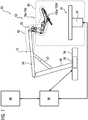
- FIG. 1 shows a schematic representation of a device 10 for robot-assisted surgery with a manipulator 12, which has a stand 14 and four manipulator arms 16a to 16d.
- the manipulator 12 can also have more or fewer manipulator arms 16a to 16d.
- Each manipulator arm 16a to 16d is connected to an instrument unit 100a to 100d via a coupling unit of the manipulator arm 16a to 16d.
- the instrument unit 100a to 100d is sterile and comprises a surgical instrument, in particular with an end effector, wherein the end effector can be moved and / or operated with the aid of the coupling unit of the manipulator arm 16a to 16d.
- the instrument unit 100a to 100d can also include an optical instrument, in particular an endoscope, and / or a medical device, in particular for applying a medicament, for dispensing a rinsing fluid and / or for sucking off rinsing fluid and / or secretion.
- an optical instrument in particular an endoscope, and / or a medical device, in particular for applying a medicament, for dispensing a rinsing fluid and / or for sucking off rinsing fluid and / or secretion.
- the stand 14 has a stand base 24 that stands on the floor of an operating room.
- the manipulator arms 16a to 16d are connected to a stand head 20 of the stand 14.
- the stand can also be a ceiling stand.
- the position of the stand head 20 can be adjusted with the aid of a stand arm drive unit 22 and with a stand base drive unit 26 arranged in the stand base 24. With the aid of the drive unit 22, stand arms 28, 30 can be moved relative to one another. With the aid of the drive unit 26, the inclination of the stand arm 30 can be changed relative to the installation surface of the stand foot 24 and / or the stand arm 30 can be rotated about a vertical axis of rotation.
- the tripod head 20 is positioned before an operation of a patient. During the operation, the position of the tripod head 20 in relation to the column 32 of an operating table 34 usually remains unchanged.
- the manipulator 12 is controlled with the aid of a control unit 36.
- the control unit 36 is connected via a data and / or control line to an input and output unit 38 which, in particular, outputs an image of the operating field to an operator in real time with the aid of at least one display unit.
- the operator makes operating inputs by means of which the instrument units 100a to 100d are positioned and operated during the operation of the patient.
- the input and output unit 38 thus serves as a man-machine interface.
- the control unit 36 is also connected to a control unit (not shown) of the operating table 34 via a control and / or data connection.
- This control and / or data connection ensures, among other things, that the position of the patient support surface or of segments of the patient support surface of the operating table 34 can only be changed if this is possible without risk for a patient to be operated on due to the positioning of the instrument units 100a to 100d .
- the operating table 34 and the instrument units 100a to 100d are arranged in a sterile operating area 40.
- the manipulator arms 16a to 16d and the stand 14 are not sterile.
- the areas of the manipulator 12 protruding into the sterile operating area 40, ie the manipulator arms 16a to 16d with coupling units, the stand head 20 and part of the stand arm 28, are in a sterile barrier 42 indicated with the aid of the dashed line, such as a sterile flexible sheath or a Sterile film, packaged sterile so that it can be safely arranged in the sterile operating area 40.
- the input and output unit 38 is arranged outside the sterile area 40 and therefore does not have to be packaged in a sterile manner.
- a sterile interface must be provided between the manipulator arm 16a to 16d and the instrument unit 100a to 100d, which ensures that the non-sterile coupling unit of the manipulator arm 16a to 16d even after the instrument unit has been separated 100a to 100d are sterile covered.
- the sterile instrument unit 100a to 100d must not come into direct contact with non-sterile parts of the coupling unit or of the manipulator arm 16a to 16d in order to contaminate the sterile instrument unit 100a to 100d and the sterile area 40 before and / or after separating the instrument unit 100a to 100d to prevent the manipulator arm 16a to 16d.
- the instrument unit 100a to 100d can thus be deposited in the sterile area 40 without contaminating further elements in the sterile area 40.
- the sterile barrier 42 is designed in such a way that it packs the manipulator arm 16a to 16d, the coupling unit, the stand head 20 and at least parts of the stand arm 28 and hermetically separates and shields them from the sterile area.
- the sterile barrier 42 can be assembled from several individual elements, with seams between the individual elements being manufactured, for example welded or glued, so that they are impermeable and allow a sterile separation of the sterile area from non-sterile units.
- the sterile barrier 42 is seamlessly made from one piece.
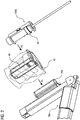
- Figure 2 Figure 16 shows a portion of the manipulator arm 16a of the apparatus of Figure 1 Figure 1 with a coupling unit 44a and the sterile barrier 42 and the instrument unit 100a in a non-coupled state.
- Elements with the same structure and / or the same function have the same reference symbols in further figures.
- the manipulator arm 16a with the instrument unit 100a and the coupling unit 44a will be described. However, the explanations also apply to the essentially identically constructed manipulator arms 16b to 16d and the instrument units 100b to 100d connected to them.
- the coupling unit 44a comprises an in Figure 2 not visible coupling unit drive element.
- the instrument unit 100a comprises a corresponding instrument drive element 54.
- the coupling unit drive element can generally also be referred to as the first drive element and the instrument drive element 54 can also generally be referred to as the second drive element.
- the sterile barrier 42 is located in Figure 2 in a folded state.
- the sterile barrier 42 comprises a flexible part, for example a sterile film, as well as a dimensionally stable part 46.
- the dimensionally stable part 46 of the sterile barrier 42 is made to fit and is at least partially elastically deformable to such an extent that it can be pulled over the coupling unit 44a and in an assembled state rests closely against at least part of an envelope surface of the coupling unit 44a. In particular, one side of the part 46 rests closely against the surface of the coupling unit 44a facing the instrument unit 100a.
- the flexible part of the sterile barrier 42 is pulled over the manipulator arm 16a.
- the flexible part of the sterile barrier 42 and the dimensionally stable part 46 are connected to one another so that they form a continuous sterile barrier between the sterile area 40 and the manipulator arm 16a, the coupling unit 44a and the stand arm 28.
- the sterile barrier 42 is pulled over the manipulator arm 16a and the dimensionally stable part 46 is pulled in the direction of the arrow P1 over the coupling unit 44a.
- the instrument unit 100a is then connected to the coupling unit 44a in the direction of the arrow P2.
- Figure 3 shows the part of the manipulator arm 16a Figure 2 with the coupling unit 44a as well as the sterile barrier 42 and the instrument unit 100a in a coupled state.
- the sterile barrier 42 in particular the dimensionally stable part 46, is pulled over the coupling unit 44a and the manipulator arm 16a.
- the instrument unit 100a was then led to a connection area of the coupling unit 44a, so that the connection area of the coupling unit 44a and a connection area of the instrument unit 100a, separated from the sterile barrier 42, are arranged opposite one another.
- the instrument unit 100a can be reversibly attached to the coupling unit 44a with the aid of straps.
- fastening with the aid of magnets or another suitable fastening of the instrument unit is possible 100a on the coupling unit 44a possible.
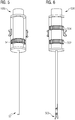
- Figure 4 shows a schematic exploded view of the instrument unit 100a with an outer part 48 and an inner part 50.
- the inner part 50 is rotatably supported within the outer part 48 in an assembled state of the instrument unit 100a.
- the inner part 50 can be rotated about an axis of rotation 52 relative to the outer part 48; in particular, the instrument drive element 54 can be rotated about the axis of rotation 52 relative to the outer part 48.
- the instrument drive element 54 is also arranged in a plane of rotation 55 and rotates in this plane 55.
- the plane 55 is orthogonal to the axis of rotation 52.
- the outer part 48 is fixedly connected to the coupling unit 44a, whereas the inner part 50 is free relative to the outer part 48 is rotatable.
- the instrument unit 100a can only comprise the inner part 50 and the inner part 50 can be rotatably mounted in the coupling unit 44a.
- the instrument unit 100a can only comprise the inner part 50, the inner part 50 being non-rotatably connected to the coupling unit 44a and the instrument drive element 54 of the instrument unit 100a being rotatably mounted within the inner part 50.
- Figure 5 shows a side view of the instrument unit 100a with the instrument drive element 54 in an assembled state.
- an end effector can be moved and / or controlled with one degree of freedom.
- the instrument drive element 54 is mechanically connected to an end effector, so that the end effector can be moved and / or controlled by rotating the instrument drive element 54.
- the end effector can be connected to the instrument drive element 54 with the aid of a transmission. For example, a rotary movement of the instrument drive element 54 can thus be converted into a linear movement along the axis of rotation 52.
- the end effector is preferably arranged at one end 57 of a shaft of the instrument unit 100a.
- the end effector is an optical system of an endoscope and has one degree of freedom.
- the optics of the endoscope and / or the Image acquisition sensor / the image acquisition sensors of the endoscope are rotated or pivoted, for example.
- the entire endoscope is preferably rotated.
- the end effector can be a surgical instrument such as scissors, a needle holder, a clamp, or a pair of forceps.
- Figure 6 shows an instrument unit 500 according to a second embodiment with a first instrument drive element 502 and a second instrument drive element 504.
- an end effector can be moved and / or controlled in two degrees of freedom.
- the end effector of the instrument unit 500 is a pair of scissors 506, which can be opened and closed, for example. In Figure 6 the scissors 506 are shown in an open state.
- the end effector can be, for example, an optical system of an endoscope, which can both be rotated about the axis of rotation 52 and, with the aid of a joint, can be moved about an axis orthogonal to the axis of rotation 52.
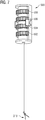
- Figure 7 shows an instrument unit 600 according to a third embodiment with a total of four instrument drive elements 602, 604, 606, 608.
- an end effector can be moved and / or controlled in four degrees of freedom.
- the end effector can be scissors or pliers.
- the end effector of the instrument unit 600 is a pair of pliers 610.
- both the levers or legs of the pliers 610 can be moved relative to one another and the pliers 610 can be rotated or tilted about an X-axis, Y-axis and / or Z-axis. This allows the end effector to be positioned easily and precisely relative to the operating field.
- the pliers 610 are shown in an open state and tilted out of the axis 52.
- the axis of rotation 52 runs through the circle centers of the four instrument drive elements 602, 604, 606, 608 of the instrument unit 600 Rotation planes arranged.
- Each of the instrument units 100a, 500, 600 can be assigned an identification element that can be read out by a readout unit in the coupling unit 44a.
- an instrument unit 100a, 500, 600 can include an RFID element that can be read out contactlessly with the aid of the coupling unit 44a.
- the identification element can include information about the instrument unit 100a, 500, 600, such as, for example, the number of degrees of freedom and number of the instrument drive elements, freedom of movement of the individual instrument drive elements and the type of end effector.
- information about the state of the instrument unit 100a, 500, 600 can be transmitted, in particular whether the instrument unit 100a, 500, 600 is unused and sterile, in order to prevent the use of contaminated instrument units 100a, 500, 600.
- interfaces can be provided between the coupling unit 44a and the instrument unit 100a, 500, 600 for the transmission of information.
- the interfaces are preferably contactless, for example optical interfaces and / or interfaces based on other electromagnetic waves.
- end effectors can also be used and driven in the instrument units 500 and 600.
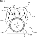
- Figures 8 to 10 each show an instrument unit 200 and a coupling unit 204 according to a fourth embodiment with an electromagnetic drive.
- Figure 8 shows a coupling unit drive element 202 in the coupling unit 204.
- a part 206 of the sterile barrier 42 is slipped over the coupling unit 204 in the direction of the arrow P3.
- the instrument unit 200 is then coupled to the coupling unit 204 in the direction of the arrow P4.
- the instrument unit 200 comprises an instrument drive element 208.
- the coupling unit drive element 202 and the instrument drive element 208 are arranged next to one another in the plane of rotation 55 orthogonally to the axis of rotation 52.
- the dimensionally stable part 206 of the sterile barrier 42 is designed and arranged such that in a region 210 along the plane of rotation 55 of the drive elements 202, 208 the dimensionally stable part 206 of the sterile barrier 42 rests closely on the coupling unit drive element 202 and does not come into contact with the instrument drive element 208.
- the dimensionally stable part 206, the coupling unit drive element 202 and the instrument drive element 208 are each designed and arranged in such a way that the distance between the coupling unit drive element 202 and the instrument drive element 208 in the coupled state is 0.05 mm to 2 mm and the dimensionally stable part 206 is the rotating one Instrument drive element 208 not touched.
- the instrument unit 200 comprises an optically detectable pattern 212, which is assigned to the instrument drive units 208 and, when the instrument drive element 208 rotates, rotates together with the latter about the axis of rotation 52.
- the pattern 212 is detected in the coupled state of the coupling unit 204 and the instrument unit 200 with the aid of one or more optical sensors of the coupling unit drive element 202, a detectable angle of rotation of the instrument drive element 208 about the axis of rotation 52 being determined without contact by a reading unit 213.
- the detectable angle of rotation is determined by a resolution of the optical sensor and a resolution of the pattern.
- the pattern 212 is designed and arranged around the circumference of the instrument drive element 208 that the optical sensor detects a clearly distinguishable part of the pattern 212 for each detectable angle of rotation. This part of the pattern 212 is different from other parts of the pattern 212 that can be detected at further angles of rotation.
- the pattern 212 can in particular be a so-called Gray code. An unambiguous determination of the position of the instrument drive element 208 about the axis of rotation 52 is thus possible.
- at least individual areas 214 made of optically transparent material are provided.
- the coupling unit drive element 202 and the instrument drive element 208 comprise in the exemplary embodiment according to FIG Figure 8 magnetic and / or magnetic field generating elements.
- Figures 9 and 10 show schematic sectional drawings of the electromagnetic drive principle according to Figure 8 , the cutting plane being the plane of rotation 55.
- the coupling unit 204 comprises a plurality of magnetic field generating elements 216a, 216b. These elements 216a, 216b are, for example, electromagnets.
- two magnetic field generating elements 216a, 216b are shown, alternatively a larger number of elements 216a, 216b are possible.
- the elements 216a, 216b are arranged in the plane of rotation 55 around part of the circumference of the instrument drive element 208.
- the coupling unit drive element 202 comprises the instrument drive element 208 at an angle of 45 ° to 180 ° around the axis of rotation.
- the polarity of the magnetic and magnetic field generating elements is in Figures 8 to 10 marked with N (north pole) or S (south pole).
- the instrument drive element 208 comprises a plurality of permanent magnets 218a, 218b along the circumference of the drive element 208. These magnets 218a, 218b have an alternately opposite polarization.
- the movement of the instrument drive element 208 is generated by the coupling unit drive element 202 according to the principle of an electric motor, in particular a stepping motor.
- the coupling unit drive element 202 is the stator and the instrument drive element 208 is the rotor.
- the magnetic field generating elements 216a, 216b are not movable, that is to say stationary, arranged in the coupling unit drive element 202.
- the instrument drive member 208 has a cylindrical shape.
- the jacket surface can only be essentially cylindrical and, for example, a shape with a base surface of a regular polygon with a center in the axis of rotation 52. At least one envelope surface enclosing this polygon is then cylindrical.
- the coupling unit drive element 202 With the help of the magnetic field generating elements 216a, 216b, the coupling unit drive element 202 generates an electromagnetic field.
- the elements 216a, 216b are controlled in such a way that they change their state with each step.
- Figure 9 shows a first state with a first polarization of the magnetic field generating elements 216a, 216b.
- Figure 10 shows a second state with a second, in each case reversed polarization of the magnetic field-generating elements 216a, 216b.
- the coupling unit drive element 202 generates a step-wise moving electromagnetic field.
- the generated electromagnetic field acts with a force on the magnetic elements 218a, 218b of the instrument drive element 208.
- the instrument drive element 208 With each change in polarization of the elements 216a, 216b, the instrument drive element 208 is rotated by the magnetic force by an angle in the direction of the arrow P5 about the axis of rotation 52 .
- the rotation of the instrument drive element 208 can be converted into a desired movement and / or control of the end effector with the aid of gears.
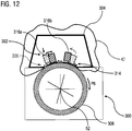
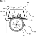
- Figures 11 to 13 show an instrument unit 300 and a coupling unit 304 according to a fifth embodiment with a drive with a mechanical power transmission.
- the mechanical power transmission is achieved in particular with the aid of a force fit and / or form fit.
- the drive can be designed as a piezo motor, for example.
- the mechanical power transmission can take place with the aid of camshafts or coupling gears.
- Figure 11 shows a coupling unit drive element 302 in the coupling unit 304.
- a dimensionally stable part 306 of the sterile barrier 42 is slipped over the coupling unit 304 in the direction of the arrow P6.
- the instrument unit 300 can then be coupled to the coupling unit 304 in the direction of the arrow P7.
- the instrument unit 300 comprises an instrument drive element 308.
- the coupling unit drive element 302 and the instrument drive element 308 are arranged next to one another along the plane of rotation 55 orthogonally to the axis of rotation 52.
- the instrument unit 300 comprises an optically detectable pattern 310.
- This pattern 310 is detected in the coupled state with the aid of one or more optical sensors of the coupling unit drive element 302 and thus a detectable angle of rotation of the instrument drive element 308 about the axis of rotation 52 is determined without contact by a reading unit 313.
- the pattern 310 is designed and arranged around the circumference of the instrument drive element 308 such that the optical sensor detects a clearly distinguishable part of the pattern 310 for each detectable angle of rotation.
- the pattern 310 can in particular be a so-called Gray code. An unambiguous determination of the position of the instrument drive element 308 about the axis of rotation 52 is thus possible.
- regions 312 made of optically transparent material are provided in the dimensionally stable part 306.
- the coupling unit drive element 302 has Figure 11 movable engagement elements which, when the instrument unit 300 is coupled to the coupling unit 304, are at least temporarily in engagement with the lateral surface of the instrument drive element 308.
- a flexible area 314 is provided in the dimensionally stable part 306, which is designed so that it enables the engagement elements to move and / or deform without being damaged to become.
- FIGS 12 and 13th show schematic sectional drawings of the mechanical drive principle according to Figure 11 , the cutting plane being the plane of rotation 55.
- the coupling unit 304 comprises the coupling unit drive element 302 with a plurality of engagement elements 316a, 316b. These elements 316a, 316b are movable and / or deformable and at least temporarily in engagement with the lateral surface of the instrument drive element 308.
- two engagement elements 316a, 316b are shown, alternatively a larger number of engagement elements 316a, 316b are possible.
- the engagement elements 316a, 316b are arranged in the plane of rotation 55 around part of the circumference of the instrument drive element 308. Furthermore, the engagement elements 316a, 316b can be moved and / or deformed in the plane of rotation 55.
- the surface of the lateral surface of the instrument drive element 308 is designed in such a way that the engagement elements 316a, 316b can form a force fit or form fit with the lateral surface.
- the instrument drive element 308 has a cylindrical shape, the lateral surface being aligned parallel to that side of the coupling unit drive element 302 which is directed towards the instrument drive element 308 in the coupled state.
- the jacket surface can only be essentially cylindrical and / or oriented essentially parallel to the coupling unit drive element 302.
- the surface of the lateral surface of the instrument drive element 308 is roughened or has a toothed ring in order to enable a secure force fit and / or form fit with the engagement element.
- an engagement element 316a, 316b is in a form or force fit with the instrument drive element 308.
- the instrument drive element 308 rotates the axis of rotation 52 in the direction of arrow P8.
- the rotation of the instrument drive element 308 can be translated into a movement and / or control of the end effector with the aid of gears.
- the engagement element 316a moves in the direction of the instrument drive element 308, enters into a force-locking connection with the instrument drive element 308 and then rotates the instrument drive element 308 in the direction of the arrow P8.
- the engagement element 316b is released from the instrument drive element 308 and moves back into a starting position counter to the direction of rotation P8.
- the engagement element 316b moves in the direction of the instrument drive element 308, enters into a force-fit connection with the instrument drive element 308 and rotates the instrument drive element 308 in the direction of the arrow P8.
- the engagement element 316a is released from the instrument drive element 308 and moves back into a starting position counter to the direction of rotation P8.
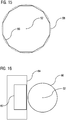
- FIG. 14 shows the instrument unit 600 according to the embodiment of FIG Figure 7 and a coupling unit 610.
- the instrument unit 600 comprises four instrument drive elements 602, 604, 606, 608.
- the coupling unit 610 comprises four coupling unit drive elements 612, 614, 616, 618.
- the coupling unit drive elements 612, 614, 616, 618 are one above the other in a plane of rotation of an instrument drive element 602, 604, 606, 608 arranged.
- the coupling unit drive elements 612, 614, 616, 618 are thus arranged in a line parallel to the axis of rotation 52 of the instrument unit 600.
- each coupling unit drive element 612, 614, 616, 618 is arranged opposite at least along part of the envelope surface of an instrument drive element 602, 604, 606, 608.
- Each instrument drive element 602, 604, 606, 608 can be assigned a circumferential pattern in order to detect the angle of rotation of the instrument drive element 602, 604, 606, 608 about the axis of rotation 52 according to the method described above.
- a dimensionally stable part 620 of a sterile barrier can comprise an optically transparent area in order to be able to detect the pattern with the aid of an optical sensor.
- the dimensionally stable part 620 of the sterile barrier further comprises a plurality of areas 622, 624, 626, 628 which are designed in such a way that, depending on the type of drive, they allow either movement and / or deformation by engagement elements without being damaged or that they are close to the coupling unit drive elements 612, 614, 616, 618 and do not come into contact with the instrument drive elements 602, 604, 606, 608.
- a drive according to the fifth embodiment in Figures 11 to 13 at least one temporary contact of the areas 622, 624, 626, 628 is provided when an engagement element with an instrument drive element 602, 604, 606, 608 is in a force fit and / or form fit.
- the number of coupling unit drive elements 612, 614, 616, 618 and instrument drive elements 602, 604, 606, 608 can differ in other embodiments, as described above in the previous embodiments. At least one coupling unit drive element and one instrument drive element are provided in each case.
- the coupling unit comprises at least as many coupling unit drive elements as the number of instrument drive elements of the instrument unit.
- each coupling unit drive element is arranged in pairs with an instrument drive element in a plane of rotation 55.
- Figure 15 shows a schematic sectional drawing of an instrument drive element 56 according to a sixth embodiment of an instrument unit, the cutting plane being the plane of rotation 55.
- the instrument drive element 56 has a shape with the base of a regular 12-cornered polygon and a center in the axis of rotation 52 exactly encloses the polygon.
- Figure 16 shows a generalized schematic representation of the drive of an instrument unit as a sectional drawing along the plane of rotation 55.
- an instrument drive element 60 is rotated about the axis of rotation 52 with the aid of a coupling unit drive element 62.
- a sterile barrier 64 encloses the coupling unit drive element 62.
- the sterile barrier 64 is arranged continuously between the coupling unit drive element 62 and the instrument drive element 60.
Landscapes
- Health & Medical Sciences (AREA)
- Engineering & Computer Science (AREA)
- Life Sciences & Earth Sciences (AREA)
- Surgery (AREA)
- Veterinary Medicine (AREA)
- Heart & Thoracic Surgery (AREA)
- Medical Informatics (AREA)
- Molecular Biology (AREA)
- Animal Behavior & Ethology (AREA)
- General Health & Medical Sciences (AREA)
- Public Health (AREA)
- Nuclear Medicine, Radiotherapy & Molecular Imaging (AREA)
- Biomedical Technology (AREA)
- Robotics (AREA)
- Pathology (AREA)
- Mechanical Engineering (AREA)
- Physics & Mathematics (AREA)
- Optics & Photonics (AREA)
- Biophysics (AREA)
- Radiology & Medical Imaging (AREA)
- Oral & Maxillofacial Surgery (AREA)
- Human Computer Interaction (AREA)
- Ophthalmology & Optometry (AREA)
- Electromagnetism (AREA)
- Manipulator (AREA)
Abstract
Eine Vorrichtung zur robotergestützten Chirurgie umfasst mindestens einen Manipulatorarm (16a bis 16d) mit einer nicht sterilen Koppeleinheit (44a, 204, 304, 610), die mindestens ein erstes Antriebselement (62, 202, 302, 612, 614, 616, 618) umfasst. Weiterhin umfasst die Vorrichtung eine in einem sterilen Bereich (40) angeordnete sterile Instrumenteneinheit (100a bis 100d, 200, 300, 500, 600), die mindestens ein zweites Antriebselement (54, 60, 208, 308, 502, 504, 602, 604, 606, 608) umfasst, das um eine Rotationsachse (52) rotierbar angeordnet ist. Das erste Antriebselement (62, 202, 302, 612, 614, 616, 618) und das zweite Antriebselement (54, 60, 208, 308, 502, 504, 602, 604, 606, 608) sind derart ausgebildet und in einem gekoppelten Zustand derart angeordnet, dass durch das erste Antriebselement (62, 202, 302, 612, 614, 616, 618) eine Kraft auf das zweite Antriebselement (54, 60, 208, 308, 502, 504, 602, 604, 606, 608), zur Rotation des zweiten Antriebselements (54, 60, 208, 308, 502, 504, 602, 604, 606, 608) um die Rotationsachse (52), ausübbar ist und im gekoppelten Zustand das erste Antriebselement (62, 202, 302, 612, 614, 616, 618) und das zweite Antriebselement (54, 60, 208, 308, 502, 504, 602, 604, 606, 608) sind in einer Rotationsebene (55) senkrecht zur Rotationsachse (52) nebeneinander angeordnet. Weiterhin umfasst die Vorrichtung eine Sterilbarriere (42,64), die zumindest zwischen dem ersten Antriebselement (62, 202, 302, 612, 614, 616, 618) und dem zweiten Antriebselement (54, 60, 208, 308, 502, 504, 602, 604, 606, 608) angeordnet ist.A device for robot-assisted surgery includes at least one manipulator arm (16a to 16d) with a non-sterile coupling unit (44a, 204, 304, 610) which includes at least a first drive element (62, 202, 302, 612, 614, 616, 618). . Furthermore, the device comprises a sterile instrument unit (100a to 100d, 200, 300, 500, 600) arranged in a sterile area (40), which has at least one second drive element (54, 60, 208, 308, 502, 504, 602, 604 , 606, 608) which is arranged to be rotatable about an axis of rotation (52). The first drive element (62, 202, 302, 612, 614, 616, 618) and the second drive element (54, 60, 208, 308, 502, 504, 602, 604, 606, 608) are designed and coupled in one Arranged in such a state that the first drive element (62, 202, 302, 612, 614, 616, 618) applies a force to the second drive element (54, 60, 208, 308, 502, 504, 602, 604, 606, 608 ), can be exercised to rotate the second drive element (54, 60, 208, 308, 502, 504, 602, 604, 606, 608) about the axis of rotation (52) and in the coupled state the first drive element (62, 202, 302 , 612, 614, 616, 618) and the second drive element (54, 60, 208, 308, 502, 504, 602, 604, 606, 608) are arranged next to one another in a plane of rotation (55) perpendicular to the axis of rotation (52). Furthermore, the device comprises a sterile barrier (42, 64) which is placed at least between the first drive element (62, 202, 302, 612, 614, 616, 618) and the second drive element (54, 60, 208, 308, 502, 504, 602, 604, 606, 608).
Description
Die Erfindung betrifft eine Vorrichtung zur robotergestützten Chirurgie mit mindestens einem Manipulatorarm mit einer nicht sterilen Koppeleinheit, die mindestens ein erstes Antriebselement hat. Die Vorrichtung hat weiterhin mindestens eine in einem sterilen Bereich angeordnete sterile Instrumenteneinheit, die mindestens ein zweites Antriebselement umfasst, das um eine Rotationsachse rotierbar angeordnet ist. Die Instrumenteneinheit ist mit der Koppeleinheit koppelbar.The invention relates to a device for robot-assisted surgery with at least one manipulator arm with a non-sterile coupling unit which has at least one first drive element. The device furthermore has at least one sterile instrument unit which is arranged in a sterile area and which comprises at least one second drive element which is arranged so as to be rotatable about an axis of rotation. The instrument unit can be coupled to the coupling unit.
In der minimalinvasiven Chirurgie werden zunehmend sogenannte Telemanipulatorsysteme, die auch als Roboterassistenzsysteme bezeichnet werden, zur robotergestützten Chirurgie eingesetzt. Das sterile Operationsfeld wird vor den nicht sterilen Elementen des Telemanipulatorsystems mit Hilfe einer sterilen Abdeckung geschützt. Durch die sterile Abdeckung wird sowohl eine Kontamination des sterilen Operationsfeldes als auch eine Verschmutzung des Telemanipulatorsystems durch Körperflüssigkeiten und/oder Gewebe des operierten Patienten oder des Operationspersonals verhindert. Dadurch wird das Risiko von Kreuzkontaminationen verringert.In minimally invasive surgery, so-called telemanipulator systems, which are also referred to as robot assistance systems, are increasingly being used for robot-assisted surgery. The sterile operating field is protected from the non-sterile elements of the telemanipulator system with the aid of a sterile cover. The sterile cover prevents both contamination of the sterile operating field and contamination of the telemanipulator system by body fluids and / or tissue of the operated patient or the operating staff. This reduces the risk of cross-contamination.
Mit Hilfe des Telemanipulatorsystems werden chirurgische Instrumente und/oder Endoskope aufgrund von Bedieneingaben in ihrer Lage und Orientierung gesteuert und kommen dabei zwangsläufig in Körperkontakt mit dem zu operierenden Patienten, sodass die chirurgischen Instrumente und/oder Endoskope mit Körperflüssigkeiten und/oder Gewebe des operierten Patienten verunreinigt werden. Gleichzeitig müssen die chirurgischen Instrumente mechanisch, elektrisch und/oder optisch an das Telemanipulatorsystem angekoppelt werden, um eine aktive Positionierung und Ausrichtung des chirurgischen Instruments sowie eine gewünschte Betätigung eines chirurgischen Instruments realisieren zu können. Hierzu ist an jedem Manipulatorarm eine Koppelschnittstelle, die als Koppeleinheit ausgebildet sein kann, vorgesehen.With the help of the telemanipulator system, surgical instruments and / or endoscopes are controlled in their position and orientation on the basis of operator inputs and thereby inevitably come into body contact with the patient to be operated on, so that the surgical instruments and / or endoscopes contaminate the body fluids and / or tissue of the operated patient will. At the same time, the surgical instruments must be mechanically, electrically and / or optically coupled to the telemanipulator system in order to achieve active positioning and alignment of the surgical instrument and a desired actuation of a surgical instrument to be able to. For this purpose, a coupling interface, which can be designed as a coupling unit, is provided on each manipulator arm.
Das während eines chirurgischen Eingriffs genutzte Material einschließlich der verwendeten chirurgischen Apparate und Instrumente und die weiteren Bestandteile des Telemanipulatorsystems können in drei Kategorien eingeteilt werden:
- Kategorie 1: Das Material ist steril und wird während des chirurgischen Eingriffs kontaminiert. Das Material wird nach der Operation entsorgt. Es erfolgt somit eine Einmalverwendung des Materials.
- Kategorie 2: Das Material ist steril, wird während des chirurgischen Eingriffs kontaminiert und nach der Operation gereinigt und sterilisiert. Es erfolgt somit eine Mehrfachverwendung des Materials. Solche mehrfach verwendeten Materialien müssen entsprechend den Anforderungen an eine prozessfähige Sterilisierbarkeit konstruiert und produziert sein.
- Kategorie 3: Das Material ist nicht steril. Während des chirurgischen Eingriffs wird durch eine sterile Abdeckung und Umverpackung eine Kontamination des sterilen Operationsfeldes verhindert. Gleichzeitig wird das nicht sterile Material vor Kontakt mit Körperflüssigkeiten und/oder Gewebe geschützt.
- Category 1: The material is sterile and will be contaminated during the surgical procedure. The material will be disposed of after the operation. The material is therefore used once.
- Category 2: The material is sterile, contaminated during surgery and cleaned and sterilized after surgery. This means that the material is used multiple times. Such materials that are used repeatedly must be designed and produced in accordance with the requirements for process-capable sterilizability.
- Category 3: The material is not sterile. During the surgical procedure, a sterile cover and outer packaging prevent contamination of the sterile operating field. At the same time, the non-sterile material is protected from contact with body fluids and / or tissue.
Ist es erforderlich, Geräte der Kategorie 1 oder der Kategorie 2 mit Geräten der Kategorie 3 zu koppeln, ist eine Sterilschnittstelle und/oder eine Sterilbarriere erforderlich, die eine Kontamination der Geräte der Kategorie 1 bzw. der Kategorie 2 durch die nicht sterilen Geräte der Kategorie 3 verhindert und umgekehrt eine Verunreinigung der Geräte der Kategorie 3 verhindert, da diese im allgemeinen als nicht sterilisierbare und nicht autoklavierbare Komponenten technisch ausgeführt sind. Die Ausführung von Geräten als sterilisierbare und autoklavierbare Komponenten erfordert eine besondere technische Auslegung des Geräts für den Sterilisationsprozess, sodass hierfür ein höherer Entwicklungsaufwand sowie ein erheblicher Validierungsaufwand zum Nachweis der Wirksamkeit des Sterilisationsprozesses erforderlich sind. Für einen solchen Nachweis ist es insbesondere erforderlich, das Gerät mehrfach nacheinander zu kontaminieren, zu sterilisieren, eine Wirksamkeitsprüfung der Sterilisation durchzuführen sowie eine Funktionsprüfung nach erfolgter Sterilisation durchzuführen. Dabei ist ein Nachweis zu erbringen, dass die Geräte nach jeder Sterilisation sicher sterilisiert und somit wiederverwendet werden könnten.If it is necessary to couple devices of
Aus dem Dokument
Somit wird mit Hilfe des Steriladapters verhindert, dass die Rotationsaktuatoren und die elektrischen Anschlüsse des sterilen chirurgischen Instruments direkt in Kontakt mit den Rotationsaktuatoren und den elektrischen Anschlüssen der Koppeleinheit des nicht sterilen Manipulatorarms kommen. Eine Kontamination des chirurgischen Instruments durch den Kontakt mit nicht sterilen Teilen des Manipulatorarms wird durch den Steriladapter verhindert. Bei dieser Lösung ist es jedoch erforderlich, dass der Steriladapter drehbar gelagerte Übertragungsmittel haben muss sowie Übertragungsmittel zur Übertragung von elektrischen Signalen, wodurch der Adapter aufwendig herzustellen und störanfällig ist. Insbesondere ist es aufwendig, die Drehbarkeit der Übertragungsmittel und die Undurchlässigkeit des Lagers der Übertragungsmittel in dem Steriladapter sicherzustellen, wenn die Übertragungsmittel in Kontakt mit Körperflüssigkeit kommen. Der Steriladapter selbst ist als Teil der Sterilfolie zur Einmalverwendung vorgesehen.The sterile adapter thus prevents the rotation actuators and the electrical connections of the sterile surgical instrument from coming into direct contact with the rotation actuators and the electrical connections of the coupling unit of the non-sterile manipulator arm. Contamination of the surgical instrument through contact with non-sterile parts of the manipulator arm is prevented by the sterile adapter. In this solution, however, it is necessary that the sterile adapter must have rotatably mounted transmission means and transmission means for the transmission of electrical signals, whereby the adapter is expensive to manufacture and prone to failure. In particular, it is expensive to ensure the rotatability of the transmission means and the impermeability of the bearing of the transmission means in the sterile adapter when the transmission means come into contact with body fluid. The sterile adapter itself is intended as part of the sterile foil for single use.
Aus dem Dokument
Grundsätzlich ist jedes Element in der Funktionskette zur Kopplung des Manipulatorarms und des Instruments eine mögliche Fehlerquelle und ist mit zusätzlichen Kosten verbunden. Je komplexer eine Sterilschleuse oder ein Steriladapter ausgebildet sind, insbesondere je mehr bewegliche Elemente vorgesehen sind, desto mehr Fehlerquellen ergeben sich. Weiterhin haben die bekannten Sterilschleusen und Steriladapter Lager und/oder Anstoßflächen von Klappen, deren Undurchlässigkeit sichergestellt sein muss.In principle, every element in the functional chain for coupling the manipulator arm and the instrument is a possible source of error and is associated with additional costs. The more complex a sterile lock or a sterile adapter is designed, in particular the more movable elements are provided, the more sources of error there are. Furthermore, the known sterile locks and sterile adapters have bearings and / or abutment surfaces for flaps, the impermeability of which must be ensured.
Es ist Aufgabe der Erfindung eine Vorrichtung zur robotergestützten Chirurgie anzugeben, bei der eine sterile Kopplung einer Koppeleinheit eines unsterilen Manipulatorarms mit einer in einem sterilen Bereich angeordneten sterilen Instrumenteneinheit einfach möglich ist, wobei eine zuverlässige Kraftübertragung zwischen der Koppeleinheit und der Instrumenteneinheit möglich ist und eine Sterilbarriere unsterile Elemente von dem sterilen Bereich abschirmt.The object of the invention is to provide a device for robot-assisted surgery in which a sterile coupling of a coupling unit of a non-sterile manipulator arm with a sterile instrument unit arranged in a sterile area is easily possible, a reliable force transmission between the coupling unit and the instrument unit being possible and a sterile barrier shields non-sterile items from the sterile area.
Diese Aufgabe wird durch eine Vorrichtung mit den Merkmalen des Anspruchs 1 gelöst. Vorteilhafte Weiterbildungen sind in den abhängigen Ansprüchen angegeben.This object is achieved by a device with the features of
Eine Vorrichtung zur robotergestützten Chirurgie umfasst mindestens einen Manipulatorarm mit einer nicht sterilen Koppeleinheit, die mindestens ein erstes Antriebselement umfasst. Weiterhin umfasst die Vorrichtung eine in einem sterilen Bereich angeordnete sterile Instrumenteneinheit, die mindestens ein zweites Antriebselement umfasst, das um eine Rotationsachse rotierbar angeordnet ist, wobei die Instrumenteneinheit mit der Koppeleinheit des Manipulatorarms koppelbar ist. Das erste Antriebselement und das zweite Antriebselement sind derart ausgebildet und in einem gekoppelten Zustand derart angeordnet, dass durch das erste Antriebselement eine Kraft auf das zweite Antriebselement, zur Rotation des zweiten Antriebselements um die Rotationsachse, ausübbar ist. Im gekoppelten Zustand sind das erste Antriebselement und das zweite Antriebselement in einer Rotationsebene senkrecht zur Rotationsachse nebeneinander angeordnet. Weiterhin umfasst die Vorrichtung eine Sterilbarriere, die zumindest zwischen dem ersten Antriebselement und dem zweiten Antriebselement angeordnet ist. Dadurch wird eine besonders kompakte und einfache Bauweise ermöglicht. Insbesondere ist die Bauweise der Sterilbarriere besonders einfach. Das erste Antriebselement kann auch als Koppeleinheitsantriebselement und das zweite Antriebselement als Instrumentenantriebselement bezeichnet werden.A device for robot-assisted surgery comprises at least one manipulator arm with a non-sterile coupling unit which comprises at least one first drive element. Furthermore, the device comprises a sterile instrument unit which is arranged in a sterile area and which comprises at least one second drive element which is arranged rotatably about an axis of rotation, the instrument unit with the Coupling unit of the manipulator arm can be coupled. The first drive element and the second drive element are designed and arranged in a coupled state in such a way that the first drive element can exert a force on the second drive element to rotate the second drive element about the axis of rotation. In the coupled state, the first drive element and the second drive element are arranged next to one another in a plane of rotation perpendicular to the axis of rotation. Furthermore, the device comprises a sterile barrier which is arranged at least between the first drive element and the second drive element. This enables a particularly compact and simple design. In particular, the construction of the sterile barrier is particularly simple. The first drive element can also be referred to as a coupling unit drive element and the second drive element as an instrument drive element.
Es ist vorteilhaft, wenn im gekoppelten Zustand das erste Antriebselement in der Rotationsebene des zweiten Antriebselements so angeordnet ist, dass eine dem zweiten Antriebselement zugewandte Oberfläche des ersten Antriebselements in zumindest einem Bereich parallel zu einer zylindrischen Mantelfläche oder einer zylindrischen Hüllmantelfläche des zweiten Antriebselements verläuft. Dadurch wird es ermöglicht, dass das erste Antriebselement die Kraft auf das zweite Antriebselement besonders sicher ausüben kannIt is advantageous if, in the coupled state, the first drive element is arranged in the plane of rotation of the second drive element in such a way that a surface of the first drive element facing the second drive element runs in at least one area parallel to a cylindrical jacket surface or a cylindrical jacket jacket surface of the second drive element. This makes it possible for the first drive element to be able to exert the force on the second drive element in a particularly reliable manner
Es ist vorteilhaft, wenn in der Rotationsebene an einer dem zweiten Antriebselement zugewandten Seite des ersten Antriebselements magnetfelderzeugende Elemente angeordnet sind und auf einer Kreisbahn um die Rotationsachse magnetfelderzeugende oder magnetische Elemente des zweiten Antriebselements angeordnet sind. Dadurch wird ein besonders sicherer Antrieb des zweiten Antriebselements ermöglicht.It is advantageous if magnetic field-generating elements are arranged in the plane of rotation on a side of the first drive element facing the second drive element and magnetic field-generating or magnetic elements of the second drive element are arranged on a circular path around the axis of rotation. This enables a particularly reliable drive of the second drive element.
Es ist besonders vorteilhaft, wenn die magnetfelderzeugenden Elemente des ersten Antriebselements Elektromagnete sind und die magnetfelderzeugenden Elemente des zweiten Antriebselements Elektromagnete mit umlaufend abwechselnden Polen sind, oder wenn die magnetfelderzeugenden Elemente des ersten Antriebselements Elektromagnete sind und die magnetischen Elemente des zweiten Antriebselements Permanentmagnete mit umlaufend abwechselnden Polen sind. Dadurch wird eine besonders kompakte und robuste Bauweise ermöglicht.It is particularly advantageous if the magnetic field generating elements of the first drive element are electromagnets and the magnetic field generating elements of the second drive element are electromagnets with circumferential alternating poles, or if the magnetic field generating elements of the first drive element are electromagnets and the magnetic elements of the second drive element are permanent magnets with alternating poles all around. This enables a particularly compact and robust design.
Es ist besonders vorteilhaft, wenn in dem ersten Antriebselement mit Hilfe der Elektromagnete Magnetfelder erzeugbar sind, durch die die Kraft auf die Permanentmagnete des zweiten Antriebselements ausübbar ist, wobei durch Änderung der Polung der Elektromagnete und/oder Änderung eines Schaltzustands der Elektromagnete das zweite Antriebselement rotiert. Dadurch wird ein zuverlässiger Antrieb des zweiten Antriebselements ermöglicht.It is particularly advantageous if magnetic fields can be generated in the first drive element with the aid of the electromagnets, through which the force can be exerted on the permanent magnets of the second drive element, the second drive element rotating by changing the polarity of the electromagnets and / or changing a switching state of the electromagnets . This enables a reliable drive of the second drive element.
Es ist vorteilhaft, wenn das erste Antriebselement mindestens einen beweglichen und/oder verformbaren Aktor umfasst, der so bewegbar und/oder verformbar ist, dass der Aktor eine Mantelfläche des zweiten Antriebselements zumindest zeitweise derart kontaktiert, dass durch Kraftschluss und/oder Formschluss zwischen dem Aktor und der Mantelfläche des zweiten Antriebselements, die Kraft auf das zweite Antriebselement ausübbar ist. Dadurch wird ein eine besonders sichere Kraftübertragung vom ersten auf das zweite Antriebselement erreicht.It is advantageous if the first drive element comprises at least one movable and / or deformable actuator which is movable and / or deformable in such a way that the actuator makes contact with a lateral surface of the second drive element at least temporarily in such a way that a force fit and / or form fit between the actuator and the lateral surface of the second drive element, the force can be exerted on the second drive element. As a result, a particularly reliable power transmission from the first to the second drive element is achieved.
Es ist besonders vorteilhaft, wenn der Aktor mindestens ein piezoelektrischer Aktor ist und mit dem, durch Kraftschluss und/oder Formschluss zwischen dem Aktor und der Mantelfläche des zweiten Antriebselements, die Kraft auf das zweite Antriebselement ausübbar ist. Dadurch wird ein besonders leistungsstarker Antrieb des zweiten Antriebselements erreicht.It is particularly advantageous if the actuator is at least one piezoelectric actuator and with which the force can be exerted on the second drive element through a force fit and / or form fit between the actuator and the outer surface of the second drive element. This achieves a particularly powerful drive for the second drive element.
Es ist vorteilhaft, wenn die dem zweiten Antriebselement zugewandte Oberfläche des ersten Antriebselements entlang eines Kreisbogens um die Rotationsachse mit einem Mittelpunktswinkel von 45° bis 180° verläuft. Dadurch wird ein besonders robuster Antrieb des zweiten Antriebselements sichergestellt.It is advantageous if the surface of the first drive element facing the second drive element runs along an arc around the axis of rotation with a central angle of 45 ° to 180 °. This ensures a particularly robust drive for the second drive element.
Es ist vorteilhaft, wenn die Sterilbarriere zumindest im Bereich zwischen dem ersten Antriebselement und dem zweiten Antriebselement eine durchgehend geschlossene Oberfläche hat. Dadurch wird eine besonders hohe Sicherheit zur Verhinderung einer Kontamination des sterilen Bereichs sichergestellt.It is advantageous if the sterile barrier has a continuously closed surface at least in the area between the first drive element and the second drive element has. This ensures a particularly high level of security for preventing contamination of the sterile area.
Es ist vorteilhaft, wenn ein Abschnitt der zwischen dem ersten Antriebselement und dem zweiten Antriebselement angeordneten Sterilbarriere entlang eines Kreisbogens um die Rotationsachse herum verläuft. Dadurch wird eine besonders sichere Anordnung der Sterilbarriere erreicht.It is advantageous if a section of the sterile barrier arranged between the first drive element and the second drive element runs along an arc around the axis of rotation. A particularly secure arrangement of the sterile barrier is achieved in this way.
Es ist vorteilhaft, wenn die Koppeleinheit mindestens eine Sensoreinheit zum Detektieren eines Drehwinkels des zweiten Antriebselements umfasst. Dadurch wird eine besonders genaue Kontrolle über die Bewegung des zweiten Antriebselement erreicht.It is advantageous if the coupling unit comprises at least one sensor unit for detecting an angle of rotation of the second drive element. In this way, particularly precise control over the movement of the second drive element is achieved.
Es ist vorteilhaft, wenn die Sensoreinheit einen optischen Sensor umfasst, der ein in einer Rotationsebene umlaufendes, codiertes, optisch erfassbares Muster auf dem zweiten Antriebselement erfasst, wobei jedem erfassbaren Drehwinkel des zweiten Antriebselements ein bei diesem Drehwinkel durch den Sensor erfassbarer Teil des Musters zugeordnet ist, wobei sich jeder durch den Sensor bei einem Drehwinkel erfassbare Teil des Musters eindeutig von anderen durch den Sensor bei anderen Drehwinkeln erfassbaren Teilen des Musters unterscheidet. Dadurch wird eine besonders sichere Erfassung des Drehwinkels erreicht.It is advantageous if the sensor unit comprises an optical sensor which detects a coded, optically detectable pattern rotating in a plane of rotation on the second drive element, each detectable angle of rotation of the second drive element being assigned a part of the pattern which can be detected by the sensor at this angle of rotation wherein each part of the pattern that can be detected by the sensor at one angle of rotation differs uniquely from other parts of the pattern that can be detected by the sensor at other angles of rotation. A particularly reliable detection of the angle of rotation is achieved in this way.
Es ist vorteilhaft, wenn in einem gekoppelten Zustand die zweiten Antriebselemente in mehreren Rotationsebenen übereinander entlang derselben Rotationsachse angeordnet sind und jedes erste Antriebselement in einer Rotationsebene mit einem zweiten Antriebselement paarweise angeordnet ist, wobei die Anzahl der Paare von Antriebselementen mindestens zwei ist, insbesondere drei oder vier ist. Dadurch sind eine Vielzahl von Freiheitsgraden eines Endeffektors der Instrumenteneinheit möglich.It is advantageous if, in a coupled state, the second drive elements are arranged in several planes of rotation one above the other along the same axis of rotation and each first drive element is arranged in pairs with a second drive element in a plane of rotation, the number of pairs of drive elements being at least two, in particular three or four is. As a result, a large number of degrees of freedom of an end effector of the instrument unit are possible.
Es ist besonders vorteilhaft, wenn mehrere Sensoreinheiten vorgesehen sind, dass die Anzahl der Sensoreinheiten mindestens der Anzahl von zweiten Antriebselementen entspricht, und dass jeweils mindestens eine Sensoreinheit den Drehwinkel eines zweiten Antriebselements erfasst. Dadurch wird eine besonders genaue und sichere Steuerung des Endeffektors erreicht.It is particularly advantageous if several sensor units are provided, that the number of sensor units corresponds at least to the number of second drive elements, and that in each case at least one sensor unit corresponds to the angle of rotation of a second Drive element recorded. A particularly precise and reliable control of the end effector is achieved in this way.
Es ist vorteilhaft, wenn die Instrumenteneinheit ein Instrument mit einem an einem distalen Ende eines Instrumentenschafts angeordneten Endeffektor umfasst, wobei das mindestens eine zweite Antriebselement mit dem Endeffektor gekoppelt ist und wobei der Endeffektor mit Hilfe des mindestens einen zweiten Antriebselements in mindestens einem Freiheitsgrad bewegbar und/oder steuerbar ist, insbesondere bei vier zweiten Antriebselementen in vier Freiheitsgraden bewegbar ist, wobei jeweils zwei der zweiten Antriebselemente eine Drehbewegung um die Längsachse des Instrumentenschafts bewirken und jeweils zwei weitere zweite Antriebselemente eine Längsbewegung in Richtung der Längsachse des Instrumentenschafts bewirken. Alternativ ist es vorteilhaft, wenn die Instrumenteneinheit ein Endoskop mit einem Endoskopschaft umfasst, wobei das mindestens eine zweite Antriebselement mit dem Endoskop, dem Endoskopschaft und/oder einer Optik des Endoskops derart gekoppelt ist, dass mit Hilfe des mindestens einen zweiten Antriebselements in mindestens einem Freiheitsgrad eine Bewegung des Endoskops, des Endoskopschafts und/oder der Optik möglich ist. Dadurch wird eine besonders große Vielfalt an verschiedenen Instrumenteneinheiten ermöglicht und eine besonders flexible Verwendung der Vorrichtung ermöglicht.It is advantageous if the instrument unit comprises an instrument with an end effector arranged at a distal end of an instrument shaft, the at least one second drive element being coupled to the end effector and the end effector being movable in at least one degree of freedom with the aid of the at least one second drive element and / or controllable, in particular is movable in four degrees of freedom with four second drive elements, two of the second drive elements each causing a rotary movement around the longitudinal axis of the instrument shaft and two further second drive elements each causing a longitudinal movement in the direction of the longitudinal axis of the instrument shaft. Alternatively, it is advantageous if the instrument unit comprises an endoscope with an endoscope shaft, the at least one second drive element being coupled to the endoscope, the endoscope shaft and / or an optical system of the endoscope in such a way that with the aid of the at least one second drive element in at least one degree of freedom a movement of the endoscope, the endoscope shaft and / or the optics is possible. This enables a particularly large variety of different instrument units and enables particularly flexible use of the device.
Weitere Merkmale und Vorteile ergeben sich aus der folgenden Beschreibung, welche in Verbindung mit den beigefügten Figuren Ausführungsbeispiele näher erläutert.Further features and advantages emerge from the following description, which explains exemplary embodiments in more detail in conjunction with the accompanying figures.
Es zeigen:
- Fig. 1
- eine schematische Darstellung einer Vorrichtung zur robotergestützten Chirurgie,
- Fig. 2
- einen Teil eines Manipulatorarms der Vorrichtung nach
Figur 1 mit einer Koppeleinheit sowie einer Sterilbarriere und einer Instrumenteneinheit gemäß einer ersten Ausführungsform in einem nicht gekoppelten Zustand, - Fig. 3
- einen Teil des Manipulatorarms mit der Koppeleinheit sowie der Sterilbarriere und der Instrumenteneinheit nach
Figur 2 in einem gekoppelten Zustand, - Fig. 4
- eine schematische Explosionszeichnung der Instrumenteneinheit,
- Fig. 5
- eine Seitenansicht der Instrumenteneinheit,
- Fig. 6
- eine Instrumenteneinheit gemäß einer zweiten Ausführungsform,
- Fig. 7
- eine Instrumenteneinheit gemäß einer dritten Ausführungsform,
- Fig. 8
- eine Koppeleinheit und eine Instrumenteneinheit mit einem elektromagnetischen Antrieb gemäß einer vierten Ausführungsform,
- Fig. 9
- eine schematische Zeichnung von magnetfelderzeugenden Elementen eines elektromagnetischen Antriebs der Koppeleinheit und der Instrumenteneinheit nach Figur 8 in einem ersten Zustand mit einer ersten Polarisierung,
- Fig. 10
- eine schematische Zeichnung des elektromagnetischen Antriebs nach
Figur 9 in einem zweiten Zustand mit einer zweiten Polarisierung, - Fig. 11
- eine Koppeleinheit und eine Instrumenteneinheit gemäß einer fünften Ausführungsform mit einer mechanischen Kraftübertragung,
- Fig. 12
- eine schematische Zeichnung von Eingriffselementen der Koppeleinheit und der Instrumenteneinheit nach
Figur 11 in einem ersten Schritt, - Fig. 13
- eine schematische Zeichnung der Eingriffselemente nach
Figur 12 in einem zweiten Schritt, - Fig. 14
- eine Koppeleinheit mit vier Koppeleinheitsantriebselementen und der Instrumenteneinheit gemäß der dritten Ausführungsform,
- Fig. 15
- eine schematische Schnittzeichnung eines Instrumentenantriebselements gemäß einer sechsten Ausführungsform einer Instrumenteneinheit, und
- Fig. 16
- eine schematische Darstellung eines Antriebs einer Instrumenteneinheit.
- Fig. 1
- a schematic representation of a device for robot-assisted surgery,
- Fig. 2
- part of a manipulator arm of the device
Figure 1 with a coupling unit and a sterile barrier and an instrument unit according to a first embodiment in a non-coupled state, - Fig. 3
- part of the manipulator arm with the coupling unit as well as the sterile barrier and the instrument unit
Figure 2 in a coupled state, - Fig. 4
- a schematic exploded view of the instrument unit,
- Fig. 5
- a side view of the instrument unit,
- Fig. 6
- an instrument unit according to a second embodiment,
- Fig. 7
- an instrument unit according to a third embodiment,
- Fig. 8
- a coupling unit and an instrument unit with an electromagnetic drive according to a fourth embodiment,
- Fig. 9
- a schematic drawing of magnetic field generating elements of an electromagnetic drive of the coupling unit and the instrument unit according to Figure 8 in a first state with a first polarization,
- Fig. 10
- a schematic drawing of the electromagnetic drive according to
Figure 9 in a second state with a second polarization, - Fig. 11
- a coupling unit and an instrument unit according to a fifth embodiment with a mechanical power transmission,
- Fig. 12
- a schematic drawing of engagement elements of the coupling unit and the instrument unit according to
Figure 11 in a first step, - Fig. 13
- a schematic drawing of the engagement elements according to
Figure 12 in a second step, - Fig. 14
- a coupling unit with four coupling unit drive elements and the instrument unit according to the third embodiment,
- Fig. 15
- a schematic sectional drawing of an instrument drive element according to a sixth embodiment of an instrument unit, and
- Fig. 16
- a schematic representation of a drive of an instrument unit.
Das Stativ 14 hat ein auf dem Fußboden eines Operationssaals stehenden Stativfuß 24. Die Manipulatorarme 16a bis 16d sind mit einem Stativkopf 20 des Stativs 14 verbunden. Bei anderen Ausführungsformen kann das Stativ auch ein Deckenstativ sein.The
Die Position des Stativkopfs 20 ist mit Hilfe einer Stativarmantriebseinheit 22 und mit einer in dem Stativfuß 24 angeordneten Stativfußantriebseinheit 26 einstellbar. Mit Hilfe der Antriebseinheit 22 sind Stativarme 28, 30 relativ zueinander bewegbar. Mit Hilfe der Antriebseinheit 26 kann die Neigung des Stativarms 30 relativ zur Aufstellfläche des Stativfußes 24 geändert und/oder der Stativarm 30 um eine senkrechte Drehachse gedreht werden. Im Allgemeinen erfolgt die Positionierung des Stativkopfs 20 vor einer Operation eines Patienten. Während der Operation bleibt die Lage des Stativkopfs 20 zu der Säule 32 eines Operationstischs 34 üblicherweise unverändert. Der Manipulator 12 wird mit Hilfe einer Steuereinheit 36 gesteuert. Die Steuereinheit 36 ist über eine Daten- und/oder Steuerleitung mit einer Ein- und Ausgabeeinheit 38 verbunden, die insbesondere ein Bild des Operationsfelds an eine Bedienperson in Echtzeit mit Hilfe mindestens einer Anzeigeeinheit ausgibt. Die Bedienperson macht Bedieneingaben, durch die die Instrumenteneinheiten 100a bis 100d während der Operation des Patienten positioniert und betätigt werden. Die Ein- und Ausgabeeinheit 38 dient somit als Mensch-Maschinen-Schnittstelle.The position of the
Die Steuereinheit 36 ist ferner über eine Steuer- und/oder Datenverbindung mit einer nicht dargestellten Steuereinheit des Operationstischs 34 verbunden. Über diese Steuer- und/oder Datenverbindung wird unter anderem sichergestellt, dass die Lage der Patientenlagerfläche oder von Segmenten der Patientenlagerfläche des Operationstischs 34 nur dann verändert werden kann, wenn dies aufgrund der Positionierung der Instrumenteneinheiten 100a bis 100d für einen zu operierenden Patienten gefahrlos möglich ist.The
Der Operationstisch 34 sowie die Instrumenteneinheiten 100a bis 100d sind in einem sterilen Operationsbereich 40 angeordnet. Die Manipulatorarme 16a bis 16d und das Stativ 14 sind nicht steril. Die in dem sterilen Operationsbereich 40 ragenden Bereiche des Manipulators 12, d.h. die Manipulatorarme 16a bis 16d mit Koppeleinheiten, der Stativkopf 20 und ein Teil des Stativarms 28, sind in einer mit Hilfe der Strichlinie angedeuteten Sterilbarriere 42, wie beispielsweise einer sterilen flexiblen Hülle oder einer Sterilfolie, steril verpackt, sodass sie gefahrlos im sterilen Operationsbereich 40 angeordnet werden können. Die Ein- und Ausgabeeinheit 38 ist außerhalb des sterilen Bereichs 40 angeordnet und muss deshalb nicht steril verpackt werden.The operating table 34 and the
Bei einer Vielzahl von Operationen müssen die Instrumenteneinheiten 100a bis 100d während der Operation aufgrund des Operationsverlaufs mehrfach gewechselt werden. Somit muss zwischen dem Manipulatorarm 16a bis 16d und der Instrumenteneinheit 100a bis 100d eine sterile Schnittstelle vorgesehen werden, die sicherstellt, dass die nicht sterile Koppeleinheit des Manipulatorarms 16a bis 16d auch nach dem Trennen der Instrumenteneinheit 100a bis 100d steril abgedeckt sind.In the case of a large number of operations, the
Darüber hinaus darf die sterile Instrumenteneinheit 100a bis 100d nicht mit unsterilen Teilen der Koppeleinheit oder des Manipulatorarms 16a bis 16d in direkten Kontakt kommen um eine Kontaminierung der sterilen Instrumenteneinheit 100a bis 100d und des sterilen Bereichs 40 vor und/oder nach dem Trennen der Instrumenteneinheit 100a bis 100d vom Manipulatorarm 16a bis 16d zu verhindern. Damit kann die Instrumenteneinheit 100a bis 100d im sterilen Bereich 40 abgelegt werden, ohne weitere Elemente im sterilen Bereich 40 zu kontaminieren. Die Sterilbarriere 42 ist so ausgebildet, dass sie den Manipulatorarm 16a bis 16d, die Koppeleinheit, den Stativkopf 20 und zumindest Teile des Stativarms 28 verpackt und vom sterilen Bereich hermetisch trennt und abschirmt. Dafür kann die Sterilbarriere 42 aus mehreren einzelnen Elementen zusammengefügt sein, wobei Nähte zwischen den einzelnen Elementen so gefertigt sind, beispielsweise geschweißt oder geklebt sind, dass sie undurchlässig sind und eine sterile Trennung des sterilen Bereichs von unsterilen Einheiten erlauben. Alternativ ist die Sterilbarriere 42 nahtlos aus einem Stück gefertigt.In addition, the
Die Koppeleinheit 44a umfasst ein in
Die Sterilbarriere 42 befindet sich in
Der flexible Teil der Sterilbarriere 42 und der formstabile Teil 46 sind miteinander verbunden, sodass sie eine durchgehende sterile Barriere zwischen dem sterilen Bereich 40 und dem Manipulatorarm 16a, der Koppeleinheit 44a und dem Stativarm 28 bilden.The flexible part of the
Vor dem Koppeln der Instrumenteneinheit 100a mit der Koppeleinheit 44a wird die Sterilbarriere 42 über den Manipulatorarm 16a gezogen und der formstabile Teil 46 in Richtung des Pfeils P1 über die Koppeleinheit 44a gezogen. Zum Koppeln wird anschließend die Instrumenteneinheit 100a in Richtung des Pfeils P2 mit der Koppeleinheit 44a verbunden.Before coupling the
Alternativ kann die Instrumenteneinheit 100a nur das Innenteil 50 umfassen und das Innenteil 50 in der Koppeleinheit 44a drehbar gelagert sein. In einer weiteren Alternative kann die Instrumenteneinheit 100a nur das Innenteil 50 umfassen, wobei das Innenteil 50 drehfest mit der Koppeleinheit 44a verbunden ist und das Instrumentenantriebselement 54 der Instrumenteneinheit 100a innerhalb des Innenteils 50 drehbar gelagert ist.Alternatively, the
Alternativ kann der Endeffektor ein chirurgisches Instrument sein, wie beispielsweise eine Schere, ein Nadelhalter, eine Klammer oder eine Zange.Alternatively, the end effector can be a surgical instrument such as scissors, a needle holder, a clamp, or a pair of forceps.
Alternativ kann der Endeffektor beispielsweise eine Optik eines Endoskops sein, die sowohl um die Rotationsachse 52 drehbar ist als auch mit Hilfe eines Gelenks um eine Achse orthogonal zur Rotationsachse 52 bewegbar ist.Alternatively, the end effector can be, for example, an optical system of an endoscope, which can both be rotated about the axis of
Die Rotationsachse 52 verläuft durch die Kreismittelpunkte der vier Instrumentenantriebselemente 602, 604, 606, 608 der Instrumenteneinheit 600. Die Instrumentenantriebselemente 602, 604, 606, 608 sind in parallelen zur Rotationsachse 52 orthogonal verlaufenden Rotationsebenen angeordnet.The axis of
Jede der Instrumenteneinheiten 100a, 500, 600 kann jeweils ein Identifizierungselement zugeordnet sein, das von einer Ausleseeinheit in der Koppeleinheit 44a ausgelesen werden kann. Beispielsweise kann eine Instrumenteneinheit 100a, 500, 600 ein RFID-Element umfassen, das berührungslos mit Hilfe der Koppeleinheit 44a ausgelesen werden kann. Das Identifizierungselement kann Informationen über die Instrumenteneinheit 100a, 500, 600 umfassen, wie beispielsweise Anzahl der Freiheitsgrade und Anzahl der Instrumentenantriebselemente, Bewegungsspielraum der einzelnen Instrumentenantriebselemente und Art des Endeffektors. Zusätzlich können Informationen über den Zustand der Instrumenteneinheit 100a, 500, 600 übermittelt werden, insbesondere ob die Instrumenteneinheit 100a, 500, 600 unbenutzt und steril ist, um eine Nutzung von verunreinigten Instrumenteneinheiten 100a, 500, 600 zu verhindern.Each of the
Darüber hinaus können weitere Schnittstellen zwischen der Koppeleinheit 44a und der Instrumenteneinheit 100a, 500, 600 zur Informationsübertragung vorgesehen sein. Vorzugsweise sind die Schnittstellen berührungslos, beispielsweise optische Schnittstellen und/oder Schnittstellen basierend auf anderen elektromagnetischen Wellen.In addition, further interfaces can be provided between the
Bei anderen Ausführungsformen können bei den Instrumenteneinheiten 500 und 600 auch andere Endeffektoren eingesetzt und angetrieben werden.In other embodiments, other end effectors can also be used and driven in the
Im Folgenden werden alternative Antriebsarten beschrieben, um ein Instrumentenantriebselement einer Instrumenteneinheit mit Hilfe einer Koppeleinheit anzutreiben.Alternative drive types are described below in order to drive an instrument drive element of an instrument unit with the aid of a coupling unit.
Die Instrumenteneinheit 200 umfasst ein Instrumentenantriebselement 208. Im gekoppelten Zustand sind das Koppeleinheitsantriebselement 202 und das Instrumentenantriebselement 208 in der Rotationsebene 55 orthogonal zur Rotationsachse 52 nebeneinander angeordnet. Der formstabile Teil 206 der Sterilbarriere 42 ist so ausgebildet und angeordnet, dass in einem Bereich 210 entlang der Rotationsebene 55 der Antriebselemente 202, 208 der formstabile Teil 206 der Sterilbarriere 42 eng an dem Koppeleinheitsantriebselement 202 anliegt und nicht in Kontakt mit dem Instrumentenantriebselement 208 kommt. Insbesondere ist der formstabile Teil 206, das Koppeleinheitsantriebselement 202 und das Instrumentenantriebselement 208 jeweils so ausgebildet und zueinander angeordnet, dass der Abstand zwischen dem Koppeleinheitsantriebselement 202 und dem Instrumentenantriebselement 208 im gekoppelten Zustand 0,05 mm bis 2 mm ist und der formstabile Teil 206 das rotierende Instrumentenantriebselement 208 nicht berührt.The
Zusätzlich umfasst die Instrumenteneinheit 200 ein optisch erfassbares Muster 212, das den Instrumentenantriebseinheiten 208 zugeordnet ist und bei einer Rotation des Instrumentenantriebselements 208 zusammen mit diesem um die Rotationsachse 52 rotiert. Das Muster 212 wird im gekoppelten Zustand der Koppeleinheit 204 und der Instrumenteneinheit 200 mit Hilfe eines oder mehrerer optischer Sensoren des Koppeleinheitsantriebselements 202 erfasst, wobei ein erfassbarer Drehwinkel des Instrumentenantriebselements 208 um die Rotationsachse 52 von einer Leseeinheit 213 berührungslos ermittelt wird. Der erfassbare Drehwinkel wird dabei von einer Auflösung des optischen Sensors und einer Auflösung des Musters bestimmt. Das Muster 212 ist so ausgebildet und um den Umfang des Instrumentenantriebselements 208 angeordnet, dass der optische Sensor für jeden erfassbaren Drehwinkel einen eindeutig unterscheidbaren Teil des Musters 212 erfasst. Dieser Teil des Musters 212 ist von anderen bei weiteren Drehwinkeln erfassbaren Teilen des Musters 212 verschieden. Das Muster 212 kann insbesondere ein sogenannter Gray-Code sein. Somit ist eine eindeutige Positionsbestimmung des Instrumentenantriebselements 208 um die Rotationsachse 52 möglich. Um eine zuverlässige optische Erfassung des Musters 212 zu gewährleisten sind in dem Teil 206 zumindest einzelne Bereiche 214 aus optisch transparentem Material vorgesehen.In addition, the
Das Koppeleinheitsantriebselement 202 und das Instrumentenantriebselement 208 umfassen im Ausführungsbeispiel nach
Das Instrumentenantriebselement 208 umfasst entlang des Umfangs des Antriebselements 208 eine Vielzahl von Permanentmagneten 218a, 218b. Diese Magnete 218a, 218b haben eine abwechselnd entgegengesetzte Polarisierung. Die Bewegung des Instrumentenantriebselements 208 wird durch das Koppeleinheitsantriebselement 202 nach dem Prinzip eines Elektromotors, insbesondere eines Schrittmotors, erzeugt. Dabei ist das Koppeleinheitsantriebselement 202 der Stator und das Instrumentenantriebselement 208 der Rotor. Die magnetfelderzeugenden Elemente 216a, 216b sind nicht bewegbar, das heißt ortsfest, in dem Koppeleinheitsantriebselement 202 angeordnet. Im Ausführungsbeispiel nach
Mit Hilfe der magnetfelderzeugenden Elemente 216a, 216b erzeugt das Koppeleinheitsantriebselement 202 ein elektromagnetisches Feld. Die Elemente 216a, 216b werden so angesteuert, dass sie mit jedem Schritt ihren Zustand ändern.
Die Instrumenteneinheit 300 umfasst ein optisch erfassbares Muster 310. Dieses Muster 310 wird im gekoppelten Zustand mit Hilfe eines oder mehrerer optischer Sensoren des Koppeleinheitsantriebselement 302 erfasst und damit ein erfassbarer Drehwinkel des Instrumentenantriebselements 308 um die Rotationsachse 52 von einer Leseeinheit 313 berührungslos ermittelt. Wie weiter oben für Instrumenteneinheit 200 beschrieben, ist das Muster 310 so ausgebildet und um den Umfang des Instrumentenantriebselements 308 angeordnet, dass der optische Sensor für jeden erfassbaren Drehwinkel einen eindeutig unterscheidbaren Teil des Musters 310 erfasst. Das Muster 310 kann insbesondere ein sogenannter Gray-Code sein. Somit ist eine eindeutige Positionsbestimmung des Instrumentenantriebselements 308 um die Rotationsachse 52 möglich. Um eine zuverlässige optische Erfassung des Musters 310 zu gewährleisten sind in dem formstabilen Teil 306 Bereiche 312 aus optisch transparentem Material vorgesehen.The
Das Koppeleinheitsantriebselement 302 hat im Ausführungsbeispiel nach
Die Oberfläche der Mantelfläche des Instrumentenantriebselements 308 ist so ausgebildet, dass die Eingriffselemente 316a, 316b mit der Mantelfläche einen Kraft- oder Formschluss bilden können. Im Ausführungsbeispiel nach
Um das Instrumentenantriebselement 308 mit Hilfe des Koppeleinheitsantriebselements 302 um die Rotationsachse 52 zu drehen, ist jeweils ein Eingriffselement 316a, 316b in Form- oder Kraftschluss mit dem Instrumentenantriebselement 308. Durch Bewegen des Eingriffselements 316a, 316b um die Rotationsachse 52 dreht sich das Instrumentenantriebselement 308 um die Rotationsachse 52 in Richtung des Pfeils P8. Die Drehung des Instrumentenantriebselements 308 kann mit Hilfe von Getrieben in eine Bewegung und/oder Steuerung des Endeffektors übersetzt werden. In
Jedes Instrumentenantriebselement 602, 604, 606, 608 kann ein umlaufendes Muster zugeordnet sein, um den Drehwinkel des Instrumentenantriebselement 602, 604, 606, 608 um die Rotationsachse 52, nach der weiter oben beschriebenen Methode, zu erfassen. Außerdem kann ein formstabiler Teil 620 einer Sterilbarriere einen optisch transparenten Bereich umfassen, um das Muster mit Hilfe eines optischen Sensors erfassen zu können.Each
Der formstabile Teil 620 der Sterilbarriere umfasst weiterhin mehrere Bereiche 622, 624, 626, 628 die so ausgebildet sind, dass sie je nach Antriebsart entweder eine Bewegung und/oder Verformung durch Eingriffselemente ermöglichen ohne beschädigt zu werden oder dass sie eng an den Koppeleinheitsantriebselementen 612, 614, 616, 618 anliegen und nicht in Kontakt mit den Instrumentenantriebselementen 602, 604, 606, 608 kommen. Im Falle eines Antriebs nach der fünften Ausführungsform in
Die Anzahl der Koppeleinheitsantriebselemente 612, 614, 616, 618 und Instrumentenantriebselemente 602, 604, 606, 608 kann in anderen Ausführungsformen abweichen, wie in den vorherigen Ausführungsbeispielen weiter oben beschrieben. Mindestens sind jeweils ein Koppeleinheitsantriebselement und ein Instrumentenantriebselement vorgesehen. Darüber hinaus umfasst die Koppeleinheit mindestens so viele Koppeleinheitsantriebselemente wie die Anzahl an Instrumentenantriebselementen der Instrumenteneinheit. Somit ist im gekoppelten Zustand jedes Koppeleinheitsantriebselement mit einem Instrumentenantriebselement in einer Rotationsebene 55 paarweise angeordnet.The number of coupling unit drive
- 1010
- Vorrichtung zur robotergestützten ChirurgieDevice for robot-assisted surgery
- 1212th
- Manipulatormanipulator
- 1414th
- Stativtripod
- 16a bis 16d16a to 16d
- ManipulatorarmManipulator arm
- 2020th
- StativkopfTripod head
- 2222nd
- StativarmantriebseinheitStand arm drive unit
- 2424
- StativfußTripod base
- 2626th
- StativfußantriebseinheitStand base drive unit
- 28, 3028, 30
- StativarmTripod arm
- 3232
- OperationstischsäuleOperating table column
- 3434
- OperationstischOperating table
- 3636
- SteuereinheitControl unit
- 3838
- Ein- und AusgabeeinheitInput and output unit
- 4040
- steriler Operationsbereichsterile operating area
- 42, 6442, 64
- SterilbarriereSterile barrier
- 44a, 204, 304, 61044a, 204, 304, 610
- KoppeleinheitCoupling unit
- 46, 206, 306, 62046, 206, 306, 620
- formstabiler Teil der Sterilbarrieredimensionally stable part of the sterile barrier
- 4848
- Außenteil der InstrumenteneinheitExternal part of the instrument unit
- 5050
- Innenteil der InstrumenteneinheitInner part of the instrument unit
- 5252
- RotationsachseAxis of rotation
- 54, 60, 208, 308, 502, 504, 602, 604, 606, 60854, 60, 208, 308, 502, 504, 602, 604, 606, 608
- InstrumentenantriebselementInstrument drive element
- 5555
- RotationsebenePlane of rotation
- 5656
- polygonförmiges Instrumentenantriebselementpolygonal instrument drive element
- 5757
- SchaftendeShaft end
- 5858
- HüllmantelflächeEnvelope surface
- 62, 202, 302, 612, 614, 616, 61862, 202, 302, 612, 614, 616, 618
- KoppeleinheitsantriebselementCoupling unit drive element
- 100a bis 100d, 200, 300, 500, 600100a to 100d, 200, 300, 500, 600
- InstrumenteneinheitInstrument unit
- 210, 622, 624, 626, 628210, 622, 624, 626, 628
- Bereich der SterilbarriereArea of the sterile barrier
- 212, 310212, 310
- Mustersample
- 214, 312214, 312
- optisch transparenter Bereichoptically transparent area
- 213, 313213, 313
- LeseeinheitReading unit
- 216a, 216b216a, 216b
- magnetfelderzeugendes Elementmagnetic field generating element
- 218a, 218b218a, 218b
- PermanentmagnetPermanent magnet
- 314314
- flexibler Bereich der Sterilbarriereflexible area of the sterile barrier
- 316a, 316b316a, 316b
- EingriffselementEngagement element
- 506, 610506, 610
- EndeffektorEnd effector
Claims (15)
mit mindestens einem Manipulatorarm (16a bis 16d) mit einer nicht sterilen Koppeleinheit (44a, 204, 304, 610), die mindestens ein erstes Antriebselement (62, 202, 302, 612, 614, 616, 618) umfasst,
mit einer in einem sterilen Bereich (40) angeordneten sterilen Instrumenteneinheit (100a bis 100d, 200, 300, 500, 600), die mindestens ein zweites Antriebselement (54, 60, 208, 308, 502, 504, 602, 604, 606, 608) umfasst, das um eine Rotationsachse (52) rotierbar angeordnet ist,
wobei die Instrumenteneinheit (100a bis 100d, 200, 300, 500, 600) mit der Koppeleinheit (44a, 204, 304, 610) des Manipulatorarms (16a bis 16d) koppelbar ist,
wobei das erste Antriebselement (62, 202, 302, 612, 614, 616, 618) und das zweite Antriebselement (54, 60, 208, 308, 502, 504, 602, 604, 606, 608) derart ausgebildet und in einem gekoppelten Zustand derart angeordnet sind, dass durch das erste Antriebselement (62, 202, 302, 612, 614, 616, 618) eine Kraft auf das zweite Antriebselement (54, 60, 208, 308, 502, 504, 602, 604, 606, 608), zur Rotation des zweiten Antriebselements (54, 60, 208, 308, 502, 504, 602, 604, 606, 608) um die Rotationsachse (52), ausübbar ist,
wobei im gekoppelten Zustand das erste Antriebselement (62, 202, 302, 612, 614, 616, 618) und das zweite Antriebselement (54, 60, 208, 308, 502, 504, 602, 604, 606, 608) in einer Rotationsebene (55) senkrecht zur Rotationsachse (52) nebeneinander angeordnet sind, und
mit einer Sterilbarriere (42,64), die zumindest zwischen dem ersten Antriebselement (62, 202, 302, 612, 614, 616, 618) und dem zweiten Antriebselement (54, 60, 208, 308, 502, 504, 602, 604, 606, 608) angeordnet ist.Device for robot-assisted surgery,
with at least one manipulator arm (16a to 16d) with a non-sterile coupling unit (44a, 204, 304, 610) which comprises at least one first drive element (62, 202, 302, 612, 614, 616, 618),
with a sterile instrument unit (100a to 100d, 200, 300, 500, 600) arranged in a sterile area (40), the at least one second drive element (54, 60, 208, 308, 502, 504, 602, 604, 606, 608), which is arranged rotatably about an axis of rotation (52),
wherein the instrument unit (100a to 100d, 200, 300, 500, 600) can be coupled to the coupling unit (44a, 204, 304, 610) of the manipulator arm (16a to 16d),
wherein the first drive element (62, 202, 302, 612, 614, 616, 618) and the second drive element (54, 60, 208, 308, 502, 504, 602, 604, 606, 608) formed in such a way and in a coupled State are arranged in such a way that the first drive element (62, 202, 302, 612, 614, 616, 618) exerts a force on the second drive element (54, 60, 208, 308, 502, 504, 602, 604, 606, 608), can be exercised to rotate the second drive element (54, 60, 208, 308, 502, 504, 602, 604, 606, 608) about the axis of rotation (52),
wherein in the coupled state the first drive element (62, 202, 302, 612, 614, 616, 618) and the second drive element (54, 60, 208, 308, 502, 504, 602, 604, 606, 608) in a plane of rotation (55) are arranged next to one another perpendicular to the axis of rotation (52), and
with a sterile barrier (42,64) which is at least between the first drive element (62, 202, 302, 612, 614, 616, 618) and the second drive element (54, 60, 208, 308, 502, 504, 602, 604, 606, 608) is arranged.
dass die magnetfelderzeugenden Elemente (216a, 216b) des ersten Antriebselements (62, 202, 302, 612, 614, 616, 618) Elektromagnete sind und die magnetischen Elemente (218a, 218b) des zweiten Antriebselements (54, 60, 208, 308, 502, 504, 602, 604, 606, 608) Permanentmagnete mit umlaufend abwechselnden Polen sind.Device according to claim 3, characterized in that the magnetic field generating elements (216a, 216b) of the first drive element (62, 202, 302, 612, 614, 616, 618) are electromagnets and the magnetic field generating elements (218a, 218b) of the second drive element ( 54, 60, 208, 308, 502, 504, 602, 604, 606, 608) are electromagnets with rotating poles, or
that the magnetic field generating elements (216a, 216b) of the first drive element (62, 202, 302, 612, 614, 616, 618) are electromagnets and the magnetic elements (218a, 218b) of the second drive element (54, 60, 208, 308, 502, 504, 602, 604, 606, 608) are permanent magnets with rotating poles.
dass die Instrumenteneinheit (100a bis 100d, 200, 300, 500, 600) ein Endoskop mit einem Endoskopschaft umfasst, wobei das mindestens eine zweite Antriebselement (54, 60, 208, 308, 502, 504, 602, 604, 606, 608) mit dem Endoskop, dem Endoskopschaft und/oder einer Optik des Endoskops derart gekoppelt ist, dass mit Hilfe des mindestens einen zweiten Antriebselements (54, 60, 208, 308, 502, 504, 602, 604, 606, 608) in mindestens einem Freiheitsgrad eine Bewegung des Endoskops, des Endoskopschafts und/oder der Optik möglich ist.Device according to one of the preceding claims, characterized in that the instrument unit (100a to 100d, 200, 300, 500, 600) comprises an instrument with an end effector (506, 610) arranged at a distal end (57) of an instrument shaft, wherein the at least one second drive element (54, 60, 208, 308, 502, 504, 602, 604, 606, 608) is coupled to the end effector (506, 610) and wherein the end effector (506, 610) with the aid of the at least one second Drive elements (54, 60, 208, 308, 502, 504, 602, 604, 606, 608) can be moved and / or controlled in at least one degree of freedom, in particular with four second drive elements (54, 60, 208, 308, 502, 504) , 602, 604, 606, 608) is movable in four degrees of freedom, with two second drive elements (54, 60, 208, 308, 502, 504, 602, 604, 606, 608) causing a rotary movement around the longitudinal axis of the instrument shaft and two further second drive elements (54, 60, 208, 308, 502, 504, 602, 604 , 606, 608) cause a longitudinal movement in the direction of the longitudinal axis of the instrument shaft, or
that the instrument unit (100a to 100d, 200, 300, 500, 600) comprises an endoscope with an endoscope shaft, the at least one second drive element (54, 60, 208, 308, 502, 504, 602, 604, 606, 608) is coupled to the endoscope, the endoscope shaft and / or an optics of the endoscope in such a way that with the help of the at least one second drive element (54, 60, 208, 308, 502, 504, 602, 604, 606, 608) in at least one degree of freedom a movement of the endoscope, the endoscope shaft and / or the optics is possible.
Applications Claiming Priority (1)
| Application Number | Priority Date | Filing Date | Title |
|---|---|---|---|
| DE102020116256.1A DE102020116256A1 (en) | 2020-06-19 | 2020-06-19 | Device for robot-assisted surgery |
Publications (1)
| Publication Number | Publication Date |
|---|---|
| EP3925563A1 true EP3925563A1 (en) | 2021-12-22 |
Family
ID=76730262
Family Applications (1)
| Application Number | Title | Priority Date | Filing Date |
|---|---|---|---|
| EP21178931.8A Pending EP3925563A1 (en) | 2020-06-19 | 2021-06-11 | Device for robotic surgery |
Country Status (4)
| Country | Link |
|---|---|
| US (1) | US20210393361A1 (en) |
| EP (1) | EP3925563A1 (en) |
| CN (1) | CN113813047A (en) |
| DE (1) | DE102020116256A1 (en) |
Families Citing this family (4)
| Publication number | Priority date | Publication date | Assignee | Title |
|---|---|---|---|---|
| CN116407155A (en) * | 2021-12-31 | 2023-07-11 | 深圳微中踪影医疗装备有限公司 | Driving device and driving system for medical equipment |
| WO2023226174A1 (en) * | 2022-05-26 | 2023-11-30 | 深圳市通甪吉祥科技有限合伙企业(有限合伙) | Surgical robot device and operating method therefor |
| US20240148411A1 (en) * | 2022-11-09 | 2024-05-09 | Cilag Gmbh International | Uterine manipulator for robotic surgical system |
| CN118614969A (en) * | 2023-03-02 | 2024-09-10 | 深圳市通甪科技有限公司 | Surgical execution device and surgical robot with same |
Citations (7)
| Publication number | Priority date | Publication date | Assignee | Title |
|---|---|---|---|---|
| US7666191B2 (en) | 1996-12-12 | 2010-02-23 | Intuitive Surgical, Inc. | Robotic surgical system with sterile surgical adaptor |
| US20150105800A1 (en) * | 2012-04-27 | 2015-04-16 | Kuka Laboratories Gmbh | Robotic Surgery System And Surgical Instrument |
| EP3025667A1 (en) | 2014-11-27 | 2016-06-01 | Avateramedical GmbH | Device for robotic surgery |
| DE102014117407A1 (en) * | 2014-11-27 | 2016-06-02 | avateramedical GmBH | Device for robotic surgery |
| US20170149323A1 (en) * | 2014-07-04 | 2017-05-25 | Abb Gomtec Gmbh | Drive unit with magnetic interface |
| US20180161111A1 (en) * | 2016-12-09 | 2018-06-14 | Ethicon Endo-Surgery, Inc. | Surgical Tool and Robotic Surgical System Interfaces |
| WO2018142281A1 (en) * | 2017-02-02 | 2018-08-09 | Ethicon Llc | Calibration of a robotic surgical tool |
Family Cites Families (1)
| Publication number | Priority date | Publication date | Assignee | Title |
|---|---|---|---|---|
| DE102008052680A1 (en) | 2008-10-22 | 2010-04-29 | Surgitaix Ag | Device for the controlled adjustment of a surgical positioning unit |
-
2020
- 2020-06-19 DE DE102020116256.1A patent/DE102020116256A1/en active Pending
-
2021
- 2021-06-11 EP EP21178931.8A patent/EP3925563A1/en active Pending
- 2021-06-17 US US17/350,578 patent/US20210393361A1/en not_active Abandoned
- 2021-06-18 CN CN202110678430.9A patent/CN113813047A/en active Pending
Patent Citations (7)
| Publication number | Priority date | Publication date | Assignee | Title |
|---|---|---|---|---|
| US7666191B2 (en) | 1996-12-12 | 2010-02-23 | Intuitive Surgical, Inc. | Robotic surgical system with sterile surgical adaptor |
| US20150105800A1 (en) * | 2012-04-27 | 2015-04-16 | Kuka Laboratories Gmbh | Robotic Surgery System And Surgical Instrument |
| US20170149323A1 (en) * | 2014-07-04 | 2017-05-25 | Abb Gomtec Gmbh | Drive unit with magnetic interface |
| EP3025667A1 (en) | 2014-11-27 | 2016-06-01 | Avateramedical GmbH | Device for robotic surgery |
| DE102014117407A1 (en) * | 2014-11-27 | 2016-06-02 | avateramedical GmBH | Device for robotic surgery |
| US20180161111A1 (en) * | 2016-12-09 | 2018-06-14 | Ethicon Endo-Surgery, Inc. | Surgical Tool and Robotic Surgical System Interfaces |
| WO2018142281A1 (en) * | 2017-02-02 | 2018-08-09 | Ethicon Llc | Calibration of a robotic surgical tool |
Also Published As
| Publication number | Publication date |
|---|---|
| CN113813047A (en) | 2021-12-21 |
| DE102020116256A1 (en) | 2021-12-23 |
| US20210393361A1 (en) | 2021-12-23 |
Similar Documents
| Publication | Publication Date | Title |
|---|---|---|
| EP3925563A1 (en) | Device for robotic surgery | |
| EP3223738B1 (en) | Device for robot-assisted surgery | |
| EP2881069B1 (en) | Surgical robot system and surgical instrument | |
| EP3025667B1 (en) | Device for robotic surgery | |
| DE60121316T2 (en) | DEVICE FOR POSITIONING, INVESTIGATION AND / OR TREATMENT, ESPECIALLY IN THE FIELD OF ENDOSCOPY AND / OR MINIMALLY INVASIVE SURGERY | |
| EP1531744B1 (en) | Device for processing parts | |
| DE102014016823B4 (en) | A method of controlling a mechatronic assistance system coupled to a support arm | |
| EP2666429A1 (en) | Medical treatment tool and manipulator | |
| WO2013160239A1 (en) | Robotic arrangement for use in medical fields | |
| EP2575662A1 (en) | Method for moving an instrument arm of a laparoscopy robot into a predeterminable relative position with respect to a trocar | |
| DE102012008535A1 (en) | Surgical robot system has instrument arrangement with instrument that is guided by robot, where degree of freedom of instrument shaft is actuated by drive train of drive train arrangement that is actuated by drive unit | |
| EP0677278A1 (en) | Stereotactic adapter and method for its use | |
| DE102013110216A1 (en) | End effector for a surgical instrument and surgical instrument with an end effector | |
| EP3273900A1 (en) | Holding arm for medical purposes having a removable operating device, and operating device therefor | |
| EP3273898B1 (en) | Surgical instrument and system | |
| WO2010040685A1 (en) | Support and guide device for an endoscopic instrument | |
| DE102007021182B4 (en) | Localization unit for a surgical X-ray diagnostic device with sterile cover foil | |
| DE102019201277A1 (en) | Device for guiding a medical flexible shaft | |
| DE102014019752A1 (en) | Holding arm for medical purposes with two mechatronic interfaces | |
| DE102018104714A1 (en) | Telemanipulator system and method for operating a telemanipulator system | |
| DE102021114151B4 (en) | Instrument feed device | |
| US20230149106A1 (en) | Surgical robotic system comprising strut assembly | |
| DE102016210846A1 (en) | robot arm | |
| ITCS20100006A1 (en) | NEW INSTRUMENTATION TO USE THE NAVI-ROBOT FOR THE CONTROL AND MICROMETRIC HANDLING OF LAPAROSCOPIC INSTRUMENTATION AND FOR THE GUIDE TO BIOPSIES BOTH ECO-GUIDED AND UNDER FLUOROSCOPY | |
| DE102022102805A1 (en) | Manipulator for robotic surgery and sterile unit |
Legal Events
| Date | Code | Title | Description |
|---|---|---|---|
| PUAI | Public reference made under article 153(3) epc to a published international application that has entered the european phase |
Free format text: ORIGINAL CODE: 0009012 |
|
| STAA | Information on the status of an ep patent application or granted ep patent |
Free format text: STATUS: THE APPLICATION HAS BEEN PUBLISHED |
|
| AK | Designated contracting states |
Kind code of ref document: A1 Designated state(s): AL AT BE BG CH CY CZ DE DK EE ES FI FR GB GR HR HU IE IS IT LI LT LU LV MC MK MT NL NO PL PT RO RS SE SI SK SM TR |
|
| B565 | Issuance of search results under rule 164(2) epc |
Effective date: 20211110 |
|
| STAA | Information on the status of an ep patent application or granted ep patent |
Free format text: STATUS: REQUEST FOR EXAMINATION WAS MADE |
|
| 17P | Request for examination filed |
Effective date: 20220622 |
|
| RBV | Designated contracting states (corrected) |
Designated state(s): AL AT BE BG CH CY CZ DE DK EE ES FI FR GB GR HR HU IE IS IT LI LT LU LV MC MK MT NL NO PL PT RO RS SE SI SK SM TR |