EP3223733B1 - Tournevis chirurgical souple - Google Patents
Tournevis chirurgical souple Download PDFInfo
- Publication number
- EP3223733B1 EP3223733B1 EP14805822.5A EP14805822A EP3223733B1 EP 3223733 B1 EP3223733 B1 EP 3223733B1 EP 14805822 A EP14805822 A EP 14805822A EP 3223733 B1 EP3223733 B1 EP 3223733B1
- Authority
- EP
- European Patent Office
- Prior art keywords
- handle member
- recess
- screw driver
- shaft member
- surgical screw
- Prior art date
- Legal status (The legal status is an assumption and is not a legal conclusion. Google has not performed a legal analysis and makes no representation as to the accuracy of the status listed.)
- Active
Links
- 230000008878 coupling Effects 0.000 claims description 28
- 238000010168 coupling process Methods 0.000 claims description 28
- 238000005859 coupling reaction Methods 0.000 claims description 28
- 238000006073 displacement reaction Methods 0.000 claims description 15
- 238000005192 partition Methods 0.000 claims description 7
- 229920000049 Carbon (fiber) Polymers 0.000 claims description 2
- 229910000831 Steel Inorganic materials 0.000 claims description 2
- 239000004917 carbon fiber Substances 0.000 claims description 2
- 239000000463 material Substances 0.000 claims description 2
- VNWKTOKETHGBQD-UHFFFAOYSA-N methane Chemical compound C VNWKTOKETHGBQD-UHFFFAOYSA-N 0.000 claims description 2
- HLXZNVUGXRDIFK-UHFFFAOYSA-N nickel titanium Chemical compound [Ti].[Ti].[Ti].[Ti].[Ti].[Ti].[Ti].[Ti].[Ti].[Ti].[Ti].[Ni].[Ni].[Ni].[Ni].[Ni].[Ni].[Ni].[Ni].[Ni].[Ni].[Ni].[Ni].[Ni].[Ni] HLXZNVUGXRDIFK-UHFFFAOYSA-N 0.000 claims description 2
- 229910001000 nickel titanium Inorganic materials 0.000 claims description 2
- 229920001296 polysiloxane Polymers 0.000 claims description 2
- 239000010959 steel Substances 0.000 claims description 2
- 239000007769 metal material Substances 0.000 claims 1
- 238000005452 bending Methods 0.000 description 2
- 230000005540 biological transmission Effects 0.000 description 2
- 238000004140 cleaning Methods 0.000 description 2
- 238000004804 winding Methods 0.000 description 2
- 210000001124 body fluid Anatomy 0.000 description 1
- 239000010839 body fluid Substances 0.000 description 1
- 210000000988 bone and bone Anatomy 0.000 description 1
- 230000001419 dependent effect Effects 0.000 description 1
- 210000003041 ligament Anatomy 0.000 description 1
- 238000003466 welding Methods 0.000 description 1
Images


Classifications
-
- A—HUMAN NECESSITIES
- A61—MEDICAL OR VETERINARY SCIENCE; HYGIENE
- A61B—DIAGNOSIS; SURGERY; IDENTIFICATION
- A61B17/00—Surgical instruments, devices or methods, e.g. tourniquets
- A61B17/56—Surgical instruments or methods for treatment of bones or joints; Devices specially adapted therefor
- A61B17/58—Surgical instruments or methods for treatment of bones or joints; Devices specially adapted therefor for osteosynthesis, e.g. bone plates, screws, setting implements or the like
- A61B17/88—Osteosynthesis instruments; Methods or means for implanting or extracting internal or external fixation devices
- A61B17/8875—Screwdrivers, spanners or wrenches
-
- A—HUMAN NECESSITIES
- A61—MEDICAL OR VETERINARY SCIENCE; HYGIENE
- A61B—DIAGNOSIS; SURGERY; IDENTIFICATION
- A61B17/00—Surgical instruments, devices or methods, e.g. tourniquets
- A61B17/16—Bone cutting, breaking or removal means other than saws, e.g. Osteoclasts; Drills or chisels for bones; Trepans
- A61B17/1613—Component parts
- A61B17/1631—Special drive shafts, e.g. flexible shafts
-
- A—HUMAN NECESSITIES
- A61—MEDICAL OR VETERINARY SCIENCE; HYGIENE
- A61B—DIAGNOSIS; SURGERY; IDENTIFICATION
- A61B17/00—Surgical instruments, devices or methods, e.g. tourniquets
- A61B17/56—Surgical instruments or methods for treatment of bones or joints; Devices specially adapted therefor
- A61B17/58—Surgical instruments or methods for treatment of bones or joints; Devices specially adapted therefor for osteosynthesis, e.g. bone plates, screws, setting implements or the like
- A61B17/68—Internal fixation devices, including fasteners and spinal fixators, even if a part thereof projects from the skin
- A61B17/80—Cortical plates, i.e. bone plates; Instruments for holding or positioning cortical plates, or for compressing bones attached to cortical plates
- A61B17/808—Instruments for holding or positioning bone plates, or for adjusting screw-to-plate locking mechanisms
-
- B—PERFORMING OPERATIONS; TRANSPORTING
- B25—HAND TOOLS; PORTABLE POWER-DRIVEN TOOLS; MANIPULATORS
- B25B—TOOLS OR BENCH DEVICES NOT OTHERWISE PROVIDED FOR, FOR FASTENING, CONNECTING, DISENGAGING OR HOLDING
- B25B15/00—Screwdrivers
-
- B—PERFORMING OPERATIONS; TRANSPORTING
- B25—HAND TOOLS; PORTABLE POWER-DRIVEN TOOLS; MANIPULATORS
- B25B—TOOLS OR BENCH DEVICES NOT OTHERWISE PROVIDED FOR, FOR FASTENING, CONNECTING, DISENGAGING OR HOLDING
- B25B23/00—Details of, or accessories for, spanners, wrenches, screwdrivers
- B25B23/0007—Connections or joints between tool parts
- B25B23/0042—Connection means between screwdriver handle and screwdriver shaft
Definitions
- the present invention relates to a flexible surgical screw driver.
- the screw driver comprises a rotatable handle member, a shaft member and a flexible member.
- the handle member is configured with a first coupling means on a distal portion thereof.
- the shaft member is configured with a drive tip on a distal portion thereof and with a second coupling means on a proximal portion thereof.
- the first and second coupling means are configured to cooperate for permitting angular displacement of the handle member and the shaft member relative to each other and for transmitting torque from the handle member to the shaft member.
- one type of prior art flexible screw driver uses a universal joint as coupling means to achieve angular displacement or angulation of the shaft member relative to the handle member and for transmitting torque from the handle member to the shaft member.
- the universal joint has two major disadvantages. First, it is very bulky. It needs much space, it is too big for easy positioning of the screw driver in correct location for use and it obstructs the view for the surgeon.
- the universal joint is not sufficiently constrained. In fact, it is fully non-constrained, resulting in that the drive tip of the screw driver is swiveling free in all directions and cannot be directed or controlled to get to a specific target such as a screw.
- a second type of prior art flexible screw driver uses a coil to permit angular displacement of the shaft member relative to the handle member and to permit torque transmission.
- This type of flexible screw driver permits direction of the drive tip of the screw driver towards a specific target.
- the coil is for natural reasons configured such that it opens and closes, allowing body fluids to enter the coil and the coil is difficult, if not impossible, to clean.
- the coil has a preferred direction, i.e. depending on in which direction the coil has its pitch, left or right, it can transfer more or less torque. Rotation in the preferred direction will close the windings of the coil and more torque can be transmitted.
- US 5,464,407 discloses an angled surgical screwdriver for inserting screws in bone tunnels in ligament reconstruction.
- the screwdriver comprises a handle having a longitudinal cannula; a flexible hollow shaft having a proximal end coupled to said handle and a distal end; and a cannulated drive tip coupled to the distal end of said flexible shaft for being rotated upon rotation of said shaft.
- the primary object of the present invention is to overcome or at least ameliorate the disadvantages of the prior art by improving the flexible surgical screw driver such that angular displacement of the rotatable handle member and the shaft member relative to each other can be performed with ease in order to reach and engage a target which is difficult to access and operate, that torque nevertheless at the same time can be transmitted from the handle member to the shaft member in a safe and effective manner without any loss thereof and that after having performed the intended operation, the angular displacement of the shaft member relative to the handle member is automatically reversed.
- the primary object of the invention is also arrived at by configuring the flexible surgical screw driver also with the above-mentioned separate flexible member, which in turn is configured such that said flexible member connects the handle member and the shaft member to each other and holds said handle member and said shaft member together such that the longitudinal axes thereof are substantially aligned and such that angular displacement of the handle member and the shaft member relative to each other such that the longitudinal axes thereof are misaligned, can be performed against the action of said flexible member.
- a flexible surgical screw driver which, when not in use, by means of the flexible member permits precise and easy direction and connection of the screw driver to a target such as a screw and which allows angular displacement by bringing the drive tip of the screw driver to engage the screw head and then, thanks to the coupling means, reposition the rotatable handle member relative to the shaft member against the action of the flexible member such that said handle member attains a position where it is easy to grip for rotation.
- the coupling means which are non-rotatably coupled to each other, torque can now be transmitted effectively from the handle member to the shaft member such that the shaft member is rotated for driving the screw with rotation.
- Fig. 1 and 2 illustrate as mentioned a preferred first embodiment of the flexible surgical screw driver according to the present invention.
- This flexible surgical screw driver comprises a rotatable handle member 1, a shaft member 2 and a flexible member 3.
- the rotatable handle member 1 is configured with a first coupling means 4. This first coupling means 4 is located on a distal end portion 1a of the handle member 1.
- the shaft member 2 is configured with a drive tip 5. The drive tip is located on a distal end portion 2a of the shaft member 2.
- the shaft member 2 is also configured with a second coupling means 6. This second coupling means 6 is found on a proximal end portion 2b of the shaft member 2.
- the first and second coupling means 4, 6 are configured to cooperate with each other such that the rotatable handle member 1 and the shaft member 2 will interact as desired according to the present invention.
- the first and second coupling means 4, 6 are configured to cooperate such that the rotatable handle member 1 and the shaft member 2 are angularly displaceable relative to each other.
- a target in the form of e.g. a screw is located such that it will be difficult to secure it with an ordinary screw driver
- the first and second coupling means 4, 6 are also configured to cooperate such that the rotatable handle member 1 and the shaft member 2 are non-rotatably connected to each other for driving the screw with rotation transmitted from the handle member.
- the handle member 1 is held and rotated preferably by hand and the rotary motion is transferred from the handle member to the shaft member 2 by means of the non-rotatable connection between said members such that the drive tip 5 on the shaft member, engaging the head of the screw, rotates the screw with sufficient torque for driving and securing thereof.
- the first and second coupling means 4, 6 are of course configured such that the non-rotatable connection between the rotatable handle member 1 and the shaft member 2 is maintained irrespective of whether said members are angularly displaced relative to each other or not, i.e. the flexible surgical screw driver according to the present invention functions also as an ordinary screw driver.
- the flexible member 3 is according to the invention configured to connect the rotatable handle member 1 and the shaft member 2 to each other and to hold said members together. This connection and holding together is realized by means of said flexible member 3 such that the longitudinal axes of the handle member 1 and the shaft member 2 are substantially aligned when the flexible surgical screw driver is not in use, i.e. in inoperative position. It is also realized by means of said flexible member 3 such that angular displacement of the handle member 1 and the shaft member 2 relative to each other such that the longitudinal axes of said members are misaligned, can be performed against the action of the flexible member 3 when the flexible surgical screw driver is in use, i.e.
- the flexible member 3 After securing of the screw and removal of the drive tip 5 of the shaft member 2 therefrom, the flexible member 3 returns the shaft member to its inoperative position relative to the handle member 1, with the longitudinal axes of said members in substantial alignment with each other.
- the flexible surgical screw driver according to the present invention provides for equal torque transmission in both directions of rotation.
- the flexible member 3 has a basic stiffness and it is thereby also easy to permit precise and easy direction of the flexible surgical screw driver towards the head of a screw and easy connection of the screw driver to the screw.
- the screw driver stays straight until a bending moment is applied thereto.
- the first coupling means on the distal end portion 1a of the rotatable handle member 1 is configured as a recess 4.
- the second coupling means on the proximal end portion 2b of the shaft member 2 is configured as a ball head 6 which is non-rotatably received in the recess 4.
- the configuration as a ball head permits in a simple manner said angular displacement of the handle member 1 and the shaft member 2 relative to each other.
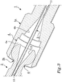
- the ball head 6 has in the illustrated embodiment according to fig. 1 and 2 as well as according to fig. 3 , in cross section, an external hexagonal shape and the recess 4 a corresponding internal hexagonal shape.
- the hexagonal shape provides in a simple manner for said non-rotatable connection of the handle member 1 and the shaft member 2 to each other.
- an angle gear drive can be used as first and second coupling means 4, 6.
- the recess 4 in the distal end portion 1a of the rotatable handle member 1 comprises a distal portion 4a for receiving the ball head 6 and a short proximal portion 4b which is tapering conically towards the proximal end of the handle member.
- the recess 4 continues proximally as an elongate recess 7 having a smaller diameter than the distal recess and which extends in the longitudinal direction of the handle member 1.
- the proximal portion 4b of the recess 4 has the conically tapering shape to avoid sharp edges which can damage the flexible member 3 where said recess transforms into the smaller diameter elongate recess 7.
- the diameter of the elongate recess 7 is relatively much larger than the diameter of the flexible member 3 in order to give room for the flexible member to flex.
- the smaller diameter elongate recess 7 ends as illustrated in fig. 1 and 2 at a partition wall 8 which has an even smaller diameter hole 9 therein.
- the proximal end of the hole 9 opens into a larger diameter proximal recess 10 in the handle member 1.
- the proximal recess 10 has a diameter which is substantially the same as the diameter of the distal portion 4a of the distal recess 4.
- the larger diameter proximal recess 10 may be located as illustrated in fig. 1 and 2 or it may be located in the proximal end portion 1b of the handle member 1 or in any other suitable position along the handle member.
- the recess 4 in the distal end portion 1a of the rotatable handle member 1 also comprises a distal portion 4a for receiving the ball head 6 and a proximal portion 4b which is tapering conically towards the proximal end of the handle member.
- the taper may vary, but is here nevertheless much longer than the conically tapering proximal portion 4b of the recess in the embodiment of fig. 1 and 2 .
- the purpose of the tapering portion 4b is the same as for the tapering proximal portion 4b of the recess 4 in the embodiment of fig. 1 and 2 , i.e. to avoid sharp edges which can damage the flexible member 3.
- the tapering proximal portion 4b of the recess 4 continues proximally as a passage 11 having a smaller diameter than the distal recess and which extends in the longitudinal direction of the handle member 1. Contrary to the smaller diameter elongate recess 7 in the embodiment of fig. 1 and 2 , the diameter of this smaller diameter passage 11 is only somewhat larger than the diameter of the flexible member 3. Thereby, no partition wall with a hole therein is needed. Instead, the smaller diameter passage 11 ends proximally directly with a larger diameter proximal recess similar to the proximal recess 10 in the embodiment of fig. 1 and 2 . This proximal recess may be located as in the embodiment of fig. 1 and 2 or it may be located in the proximal end portion of the handle member 1 or in any other suitable position along the handle member.
- the ball head 6 on the proximal end portion 2b of the shaft member 2 is configured with a recess 12 which is tapering towards the distal end portion 2a of the shaft member.
- the purpose of the tapering recess 12 is the same as for the conical proximal part of the recess 4 in the embodiment of fig. 1 and 2 and for the tapering portion 4b of the same recess in the embodiment of fig. 3 , i.e. to avoid sharp edges which can damage the flexible member 3.
- the tapering recess 12 continues distally as a smaller diameter passage 13, i.e. the diameter of the passage is smaller than the diameter of the recess. This smaller diameter passage 13 extends in the longitudinal direction of the shaft member 2.
- the smaller diameter passage 13 ends in the illustrated embodiment of fig. 1 and 2 a short distance distally of the recess 12, but may alternatively extend through the entire shaft member 2 and end short of the drive tip 5 at the distal end portion 2a thereof or at any other suitable point along said shaft member.
- the flexible member is according to the present invention preferably configured as a spring wire 3 which at its distal end is fixedly attached to the shaft member 2 and which at its proximal end is releasably located in the rotatable handle member 1, as in the embodiment illustrated in fig. 1 and 2 .
- the spring wire 3 may be fixedly attached also to the handle member 1.
- the spring wire 3 must be elastically deformable such that it can be bent and stretched during angular displacement of the handle member 1 and the shaft member 2 relative to each other and such that it can return to its original state and thereby return the handle member and the shaft member to their inoperative position relative to each other when the flexible surgical screw driver is no longer in use.
- the spring wire 3 may be metallic, e.g.
- the diameter of the spring wire 3 is chosen based on the desired stiffness of the screw driver, i.e. based on the desired force to bring about angular displacement of the handle member 1 and the shaft member 2 relative to each other and the desired spring force for returning said handle member and said shaft member to their inoperative position.
- the flexible member By configuring the flexible member as a spring wire 3, the flexible member has been given the best possible shape for location in the limited space provided in the rotatable handle member 1 and the shaft member 2. Accordingly, the spring wire 3 is configured for fixed attachment in and extension through the smaller diameter passage 13 as well as through the tapering proximal recess 12 in the shaft member 2.
- the spring wire 3 may be fixedly attached in the shaft member 2 e.g. by spot welding through a lateral hole (not illustrated) in the shaft member or along its entire length by means of a laser, or by a simple press fit in the smaller diameter passage 13 in the shaft member.
- the spring wire 3 is further configured for extension through the distal recess 4, the smaller diameter elongate recess 7 and the hole 9 in the partition wall 8 and into the larger diameter proximal recess 10 in the rotatable handle member 1 for releasable location therein.
- the spring wire 3 is configured for extension through the distal recess 4 and the smaller diameter passage 11 and into the larger diameter proximal recess 10 in the handle member 1 for releasable connection therein.
- the proximal end portion of the spring wire 3 By configuring the proximal end portion of the spring wire 3 with an enlarged part 3a which may be integral with the spring wire or a separate member which is fixedly attached to said proximal end portion of the spring wire, it is possible to achieve the releasable location of said spring wire in the larger diameter proximal recess 10 in the handle member 1 in a simple manner.
- the enlarged part 3a of the spring wire will move towards and engage the partition wall 8 around the hole 9 therein or it will move towards the distal wall defining the proximal recess 10 in the handle member and engage said distal wall around the opening into the smaller diameter passage 11.
- the enlarged part 3a of the spring wire 3 functions as a stop element.
- the enlarged part 3a of the spring wire may e.g. be a ball or a cylindrical element as in the embodiment of fig. 1 and 2 . Releasable connection of the spring wire 3 will also ease the tension thereof during bending and stretching.
- the flexible surgical screw driver according to the present invention may be used as an ordinary screw driver since the spring force of the as a spring wire configured flexible member 3 is capable of holding the rotatable handle member 1 and the shaft member 2 such that the longitudinal axes thereof are substantially aligned.
- the first and second coupling means 4, 6 see to that the handle member 1 and the shaft member 2 are non-rotatably connected to each other, such that rotation of the handle member is transmitted from the handle member to the shaft member and from the shaft member to the target, e.g. the screw, such that sufficient torque is provided for driving and securing the screw.
- the first and second coupling means 4, 6 are configured such that the handle member 1 and the shaft member 2 thereby still are non-rotatably connected to each other, such that rotation of the handle member is transmitted from the handle member to the angularly displaced shaft member and from the shaft member to the screw with sufficient torque for effective driving and securing of the screw.
- the conically tapering parts 4b and 12 of the handle member 1 and the shaft member 2 respectively see to that the flexible member 3 is not damaged during the rotation and the smaller diameter parts 7; 11 see to that there is sufficient space for the flexible member to flex if necessary. After securing of the screw and removal of the drive tip 5 of the screw driver from the screw head and while still holding the handle member, the flexible member 3 strives to return to its unbent and unstretched condition.
- the rotatable handle member 1 comprises preferably two parts, one of which is illustrated in fig. 1 and 2 .
- the two parts are configured such that they when assembled define the recesses 4, 7, 10 for the flexible member, i.e. the spring wire 3, therein.
- the two parts are configured such that they when assembled define the distal and proximal recesses 4, 10 as well as the intermediate smaller diameter passage 11 for the flexible member, i.e. the spring wire 3, therein.
- the flexible member 3 is fixedly attached to the handle member 1, it should be attached only to one part thereof, such that disassembly of the handle member for cleaning is still possible.
- the two parts are held together by means of a suitable clamping device, e.g.
- a sleeve 14 which is threaded onto said handle member parts, as in the illustrated embodiment according to fig. 1 and 2 , which each is configured with an outer threading 15 which correspond with an inner threading 16 of the sleeve.
- the clamping device is configured also to be gripped and held by a surgeon when the screw driver is used.
- the shaft member 2 comprises on the other hand one, integral part only. This integral part is configured with the recess 12 and the smaller diameter passage 13 for the flexible member, i.e. the spring wire 3.
Claims (19)
- Tournevis chirurgical flexible, comprenant
un élément de poignée pivotant (1), un élément de manche (2) et un élément flexible (3),
dans lequel ledit élément de poignée (1) est configuré avec un premier moyen de couplage (4) sur une partie d'extrémité distale (1a) de celui-ci,
dans lequel ledit élément de manche (2) est configuré avec une pointe d'entraînement (5) sur une partie d'extrémité distale (2a) de celui-ci et un deuxième moyen de couplage (6) sur une partie d'extrémité proximale (2b) de celui-ci,
dans lequel lesdits premier et deuxième moyens de couplage (4, 6) sont configurés pour coopérer de sorte que ledit élément de poignée (1) et ledit élément de manche (2) puissent être déplacés angulairement l'un par rapport à l'autre et de sorte que ledit élément de poignée (1) et ledit élément de manche (2) soient couplés de manière non pivotante l'un à l'autre pour entraîner une cible telle qu'une vis avec une rotation transmise depuis l'élément de poignée (1), et
dans lequel ledit élément flexible (3) est configuré pour raccorder l'élément de poignée (1) et l'élément de manche (2) l'un à l'autre et maintenir lesdits élément de poignée (1) et élément de manche (2) ensemble de sorte que les axes longitudinaux de ceux-ci soient sensiblement alignés et de sorte qu'un déplacement angulaire de l'élément de poignée (1) et de l'élément de manche (2) l'un par rapport à l'autre, de sorte que les axes longitudinaux de ceux-ci soient mal alignés, puisse être exécuté contre l'action dudit élément flexible (3). - Tournevis chirurgical flexible selon la revendication 1,
dans lequel le premier moyen de couplage sur la partie d'extrémité distale (1a) de l'élément de poignée pivotant (1) est configuré comme un renfoncement (4), et
dans lequel le deuxième moyen de couplage sur la partie d'extrémité proximale (2b) de l'élément de manche (2) est configuré comme une tête sphérique (6) qui est reçue de manière non pivotante dans ledit renfoncement (4). - Tournevis chirurgical flexible selon la revendication 2, dans lequel le renfoncement (4) dans la partie d'extrémité distale (1a) de l'élément de poignée pivotant (1) a une forme intérieurement hexagonale et la tête sphérique (6) sur la partie d'extrémité proximale (2b) de l'élément de manche (2) une forme extérieurement hexagonale.
- Tournevis chirurgical flexible selon la revendication 2 ou 3, dans lequel le renfoncement (4) dans la partie d'extrémité distale (1a) de l'élément de poignée pivotant (1) comprend une partie distale (4a) pour recevoir la tête sphérique (6) et une partie proximale (4b) qui rétrécit en direction de l'extrémité proximale de l'élément de poignée (1).
- Tournevis chirurgical flexible selon la revendication 4, dans lequel la partie proximale rétrécissante (4b) du renfoncement (4) est configurée de manière proximale pour continuer comme un renfoncement allongé de diamètre inférieur (7) qui est configuré pour s'étendre dans la direction longitudinale de l'élément de poignée (1).
- Tournevis chirurgical flexible selon la revendication 5, dans lequel le renfoncement allongé de diamètre inférieur (7) est configuré pour se terminer à une paroi de séparation (8), ladite paroi de séparation ayant un trou (9) dans celle-ci, l'extrémité proximale de laquelle est configurée pour s'ouvrir en un renfoncement proximal de diamètre supérieur (10) dans l'élément de poignée (1).
- Tournevis chirurgical flexible selon la revendication 4, dans lequel la partie proximale rétrécissante (4b) du renfoncement (4) est configurée de manière proximale pour continuer comme un passage de diamètre inférieur (11) qui est configuré pour s'étendre dans la direction longitudinale de l'élément de poignée (1).
- Tournevis chirurgical flexible selon la revendication 7, dans lequel le passage de diamètre inférieur (11) est configuré pour se terminer de manière proximale avec un renfoncement proximal de diamètre supérieur (10) dans l'élément de poignée (1).
- Tournevis chirurgical flexible selon l'une quelconque des revendications 2 à 8, dans lequel la tête sphérique (6) sur la partie d'extrémité proximale (2b) de l'élément de manche (2) est configurée avec un renfoncement (12) qui rétrécit en direction de la partie distale de l'élément de manche (2).
- Tournevis chirurgical flexible selon la revendication 9, dans lequel le renfoncement rétrécissant (12) dans la tête sphérique (6) sur la partie d'extrémité proximale (2b) de l'élément de manche (2) est configuré de manière distale pour continuer comme un passage de diamètre inférieur (13) qui est configuré pour s'étendre dans la direction longitudinale de l'élément de manche (2).
- Tournevis chirurgical flexible selon la revendication 10, dans lequel le passage de diamètre inférieur (13) dans l'élément de manche (2) est configuré pour se terminer au niveau de la pointe d'entraînement (5) au niveau de la partie d'extrémité distale (2a) de celui-ci.
- Tournevis chirurgical flexible selon l'une quelconque des revendications 1 à 11, dans lequel l'élément flexible est configuré comme un fil de ressort (3) qui, au niveau de son extrémité distale, est configuré pour un attachement fixe à l'élément de manche (2) et qui, au niveau de son extrémité proximale, est configuré pour un emplacement amovible dans l'élément de poignée (1).
- Tournevis chirurgical flexible selon la revendication 12, dans lequel le fil de ressort (3) est configuré pour un attachement fixe dans et une extension à travers le passage de diamètre inférieur (13) ainsi qu'à travers le renfoncement proximal rétrécissant (12) dans l'élément de manche (2) et pour une extension à travers le renfoncement distal (4), le renfoncement allongé de diamètre inférieur (7) et le trou (9) dans la paroi de séparation (8) et dans le renfoncement proximal de diamètre supérieur (10) dans l'élément de poignée (1) pour un emplacement amovible dans celui-ci.
- Tournevis chirurgical flexible selon la revendication 13, dans lequel l'élément de poignée (1) comprend deux parties qui sont configurées de sorte qu'elles, lorsqu'elles sont assemblées, définissent les renfoncements (4, 7, 10) pour le fil de ressort (3) dans ceux-ci et qui sont maintenues ensemble au moyen d'un manchon (14) qui est fileté sur lesdites parties d'élément de poignée.
- Tournevis chirurgical flexible selon la revendication 12, dans lequel le fil de ressort (3) est configuré pour un attachement fixe dans et une extension à travers le passage de diamètre inférieur (13) ainsi qu'à travers le renfoncement proximal rétrécissant (12) dans l'élément de manche (2) et pour une extension à travers le renfoncement distal (4) et le passage de diamètre inférieur (11) et dans le renfoncement proximal de diamètre supérieur (10) dans l'élément de poignée (1) pour un emplacement amovible dans celui-ci.
- Tournevis chirurgical flexible selon la revendication 15, dans lequel l'élément de poignée (1) comprend deux parties qui sont configurées de sorte qu'elles, lorsqu'elles sont assemblées, définissent les renfoncements distal et proximal (4, 10) ainsi que le passage intermédiaire de diamètre inférieur (11) pour le fil de ressort (3) dans ceux-ci et qui sont maintenues ensemble au moyen d'un manchon (14) qui est fileté sur lesdites parties d'élément de poignée.
- Tournevis chirurgical flexible selon l'une quelconque des revendications 12 à 16, dans lequel la partie d'extrémité proximale du fil de ressort (3) est configurée avec une partie élargie (3a) pour un emplacement amovible dans le renfoncement proximal de diamètre supérieur (10) dans l'élément de poignée (1).
- Tournevis chirurgical flexible selon l'une quelconque des revendications 12 à 17, dans lequel l'élément de manche (2) comprend une partie intégrante qui est configurée avec le renfoncement (12) et le passage de diamètre inférieur (13) pour le fil de ressort (3).
- Tournevis chirurgical flexible selon l'une quelconque des revendications 1 à 18, dans lequel l'élément flexible (3) est fait d'un matériau métallique, par exemple de l'acier ou du nitinol, ou d'une matière plastique, par exemple du silicone, ou d'une fibre de carbone.
Applications Claiming Priority (1)
| Application Number | Priority Date | Filing Date | Title |
|---|---|---|---|
| PCT/EP2014/075530 WO2016082864A1 (fr) | 2014-11-25 | 2014-11-25 | Tournevis chirurgical souple |
Publications (2)
| Publication Number | Publication Date |
|---|---|
| EP3223733A1 EP3223733A1 (fr) | 2017-10-04 |
| EP3223733B1 true EP3223733B1 (fr) | 2019-08-28 |
Family
ID=52002913
Family Applications (1)
| Application Number | Title | Priority Date | Filing Date |
|---|---|---|---|
| EP14805822.5A Active EP3223733B1 (fr) | 2014-11-25 | 2014-11-25 | Tournevis chirurgical souple |
Country Status (5)
| Country | Link |
|---|---|
| US (1) | US10779871B2 (fr) |
| EP (1) | EP3223733B1 (fr) |
| JP (1) | JP6403900B2 (fr) |
| ES (1) | ES2750537T3 (fr) |
| WO (1) | WO2016082864A1 (fr) |
Families Citing this family (3)
| Publication number | Priority date | Publication date | Assignee | Title |
|---|---|---|---|---|
| DE102016011947A1 (de) * | 2016-10-05 | 2018-04-05 | Bluewater Medical GmbH | Schraube mit einem Kopfteil, einem Gewindeteil und einem Verbindungsteil |
| KR101993362B1 (ko) * | 2017-09-08 | 2019-06-26 | (주)케어테크 | 늑골 시술용 플렉시블 드라이버 구조체 |
| WO2019071273A1 (fr) | 2017-10-06 | 2019-04-11 | Paragon 28, Inc. | Système de fixation de ligament, implants, dispositifs, et procédés d'utilisation |
Family Cites Families (12)
| Publication number | Priority date | Publication date | Assignee | Title |
|---|---|---|---|---|
| JPS5545489A (en) | 1978-08-03 | 1980-03-31 | Matsushino Entaapuraisesu Inc | Ball and its preparation |
| JPS5614053Y2 (fr) * | 1978-09-21 | 1981-04-01 | ||
| US4876929A (en) * | 1988-09-15 | 1989-10-31 | Burton Kozak | Portable screw driver having flexible extension shaft |
| US5464407A (en) * | 1991-02-19 | 1995-11-07 | Mcguire; David A. | Flexible surgical screwdriver and methods of arthroscopic ligament reconstruction |
| SE504025C2 (sv) * | 1992-12-07 | 1996-10-21 | Johan Pelkonen | Handverktyg för åtdragning och lossning av ett skruvbart organ |
| JPH08108375A (ja) * | 1994-08-19 | 1996-04-30 | Yoshitaka Takahashi | 狭所用ねじ回し |
| US7296804B2 (en) * | 2000-06-24 | 2007-11-20 | Precimed S.A. | Hand-held instrument holder for surgical use |
| US6827722B1 (en) * | 2001-12-11 | 2004-12-07 | Biomet, Inc. | Method and apparatus for use of a guide wire capturing surgical instrument |
| US20100064860A1 (en) * | 2008-09-18 | 2010-03-18 | Combined Products Co. #1 Inc. | Extension shaft for holding a tool for rotary driven motion |
| US8568417B2 (en) * | 2009-12-18 | 2013-10-29 | Charles River Engineering Solutions And Technologies, Llc | Articulating tool and methods of using |
| US20120109142A1 (en) * | 2010-10-27 | 2012-05-03 | Alan Dayan | Surgical Screwdriver |
| US9080611B2 (en) * | 2010-12-01 | 2015-07-14 | Howmedica Osteonics Corp. | Drive tool having an angled connector |
-
2014
- 2014-11-25 ES ES14805822T patent/ES2750537T3/es active Active
- 2014-11-25 WO PCT/EP2014/075530 patent/WO2016082864A1/fr active Application Filing
- 2014-11-25 EP EP14805822.5A patent/EP3223733B1/fr active Active
- 2014-11-25 JP JP2017546007A patent/JP6403900B2/ja active Active
- 2014-11-25 US US15/527,118 patent/US10779871B2/en active Active
Non-Patent Citations (1)
| Title |
|---|
| None * |
Also Published As
| Publication number | Publication date |
|---|---|
| WO2016082864A1 (fr) | 2016-06-02 |
| JP2017535402A (ja) | 2017-11-30 |
| EP3223733A1 (fr) | 2017-10-04 |
| US10779871B2 (en) | 2020-09-22 |
| US20190090926A1 (en) | 2019-03-28 |
| JP6403900B2 (ja) | 2018-10-10 |
| ES2750537T3 (es) | 2020-03-26 |
Similar Documents
| Publication | Publication Date | Title |
|---|---|---|
| US10869671B2 (en) | Articulation joint for apparatus for endoscopic procedures | |
| US7604640B2 (en) | Device and system for applying rotary impact | |
| JP2018532492A5 (fr) | ||
| US5464407A (en) | Flexible surgical screwdriver and methods of arthroscopic ligament reconstruction | |
| US4706659A (en) | Flexible connecting shaft for intramedullary reamer | |
| EP3223733B1 (fr) | Tournevis chirurgical souple | |
| JP6955472B2 (ja) | 振動伝達ハンドピースからの駆動運動を医療用、特に歯科用器具に伝達する結合装置 | |
| JP6672183B2 (ja) | 解剖学的インプラント用の分離可能なガイド器具 | |
| JP6129114B2 (ja) | 処置具用アダプタおよび手術用マニピュレータシステム | |
| EP3815631B1 (fr) | Foret chirurgical et méthode de production correspondante | |
| US10117692B2 (en) | Fixing means for fixation of bone fragments at bone fractures | |
| US20230121028A1 (en) | Surgical Instrument For Transmitting Torque | |
| AU2019409329B2 (en) | Surgical screwdriver | |
| JP2022515138A (ja) | 外科用ドライバー |
Legal Events
| Date | Code | Title | Description |
|---|---|---|---|
| STAA | Information on the status of an ep patent application or granted ep patent |
Free format text: STATUS: THE INTERNATIONAL PUBLICATION HAS BEEN MADE |
|
| PUAI | Public reference made under article 153(3) epc to a published international application that has entered the european phase |
Free format text: ORIGINAL CODE: 0009012 |
|
| STAA | Information on the status of an ep patent application or granted ep patent |
Free format text: STATUS: REQUEST FOR EXAMINATION WAS MADE |
|
| 17P | Request for examination filed |
Effective date: 20170512 |
|
| AK | Designated contracting states |
Kind code of ref document: A1 Designated state(s): AL AT BE BG CH CY CZ DE DK EE ES FI FR GB GR HR HU IE IS IT LI LT LU LV MC MK MT NL NO PL PT RO RS SE SI SK SM TR |
|
| AX | Request for extension of the european patent |
Extension state: BA ME |
|
| DAX | Request for extension of the european patent (deleted) | ||
| GRAP | Despatch of communication of intention to grant a patent |
Free format text: ORIGINAL CODE: EPIDOSNIGR1 |
|
| STAA | Information on the status of an ep patent application or granted ep patent |
Free format text: STATUS: GRANT OF PATENT IS INTENDED |
|
| INTG | Intention to grant announced |
Effective date: 20190318 |
|
| GRAS | Grant fee paid |
Free format text: ORIGINAL CODE: EPIDOSNIGR3 |
|
| GRAA | (expected) grant |
Free format text: ORIGINAL CODE: 0009210 |
|
| STAA | Information on the status of an ep patent application or granted ep patent |
Free format text: STATUS: THE PATENT HAS BEEN GRANTED |
|
| AK | Designated contracting states |
Kind code of ref document: B1 Designated state(s): AL AT BE BG CH CY CZ DE DK EE ES FI FR GB GR HR HU IE IS IT LI LT LU LV MC MK MT NL NO PL PT RO RS SE SI SK SM TR |
|
| REG | Reference to a national code |
Ref country code: GB Ref legal event code: FG4D |
|
| REG | Reference to a national code |
Ref country code: CH Ref legal event code: EP |
|
| REG | Reference to a national code |
Ref country code: AT Ref legal event code: REF Ref document number: 1171422 Country of ref document: AT Kind code of ref document: T Effective date: 20190915 |
|
| REG | Reference to a national code |
Ref country code: IE Ref legal event code: FG4D |
|
| REG | Reference to a national code |
Ref country code: DE Ref legal event code: R096 Ref document number: 602014052629 Country of ref document: DE |
|
| REG | Reference to a national code |
Ref country code: NL Ref legal event code: FP |
|
| REG | Reference to a national code |
Ref country code: LT Ref legal event code: MG4D |
|
| PG25 | Lapsed in a contracting state [announced via postgrant information from national office to epo] |
Ref country code: NO Free format text: LAPSE BECAUSE OF FAILURE TO SUBMIT A TRANSLATION OF THE DESCRIPTION OR TO PAY THE FEE WITHIN THE PRESCRIBED TIME-LIMIT Effective date: 20191128 Ref country code: BG Free format text: LAPSE BECAUSE OF FAILURE TO SUBMIT A TRANSLATION OF THE DESCRIPTION OR TO PAY THE FEE WITHIN THE PRESCRIBED TIME-LIMIT Effective date: 20191128 Ref country code: LT Free format text: LAPSE BECAUSE OF FAILURE TO SUBMIT A TRANSLATION OF THE DESCRIPTION OR TO PAY THE FEE WITHIN THE PRESCRIBED TIME-LIMIT Effective date: 20190828 Ref country code: PT Free format text: LAPSE BECAUSE OF FAILURE TO SUBMIT A TRANSLATION OF THE DESCRIPTION OR TO PAY THE FEE WITHIN THE PRESCRIBED TIME-LIMIT Effective date: 20191230 Ref country code: HR Free format text: LAPSE BECAUSE OF FAILURE TO SUBMIT A TRANSLATION OF THE DESCRIPTION OR TO PAY THE FEE WITHIN THE PRESCRIBED TIME-LIMIT Effective date: 20190828 Ref country code: SE Free format text: LAPSE BECAUSE OF FAILURE TO SUBMIT A TRANSLATION OF THE DESCRIPTION OR TO PAY THE FEE WITHIN THE PRESCRIBED TIME-LIMIT Effective date: 20190828 Ref country code: FI Free format text: LAPSE BECAUSE OF FAILURE TO SUBMIT A TRANSLATION OF THE DESCRIPTION OR TO PAY THE FEE WITHIN THE PRESCRIBED TIME-LIMIT Effective date: 20190828 |
|
| PG25 | Lapsed in a contracting state [announced via postgrant information from national office to epo] |
Ref country code: AL Free format text: LAPSE BECAUSE OF FAILURE TO SUBMIT A TRANSLATION OF THE DESCRIPTION OR TO PAY THE FEE WITHIN THE PRESCRIBED TIME-LIMIT Effective date: 20190828 Ref country code: GR Free format text: LAPSE BECAUSE OF FAILURE TO SUBMIT A TRANSLATION OF THE DESCRIPTION OR TO PAY THE FEE WITHIN THE PRESCRIBED TIME-LIMIT Effective date: 20191129 Ref country code: IS Free format text: LAPSE BECAUSE OF FAILURE TO SUBMIT A TRANSLATION OF THE DESCRIPTION OR TO PAY THE FEE WITHIN THE PRESCRIBED TIME-LIMIT Effective date: 20191228 Ref country code: RS Free format text: LAPSE BECAUSE OF FAILURE TO SUBMIT A TRANSLATION OF THE DESCRIPTION OR TO PAY THE FEE WITHIN THE PRESCRIBED TIME-LIMIT Effective date: 20190828 Ref country code: LV Free format text: LAPSE BECAUSE OF FAILURE TO SUBMIT A TRANSLATION OF THE DESCRIPTION OR TO PAY THE FEE WITHIN THE PRESCRIBED TIME-LIMIT Effective date: 20190828 |
|
| REG | Reference to a national code |
Ref country code: AT Ref legal event code: MK05 Ref document number: 1171422 Country of ref document: AT Kind code of ref document: T Effective date: 20190828 |
|
| REG | Reference to a national code |
Ref country code: ES Ref legal event code: FG2A Ref document number: 2750537 Country of ref document: ES Kind code of ref document: T3 Effective date: 20200326 |
|
| PG25 | Lapsed in a contracting state [announced via postgrant information from national office to epo] |
Ref country code: TR Free format text: LAPSE BECAUSE OF FAILURE TO SUBMIT A TRANSLATION OF THE DESCRIPTION OR TO PAY THE FEE WITHIN THE PRESCRIBED TIME-LIMIT Effective date: 20190828 |
|
| PG25 | Lapsed in a contracting state [announced via postgrant information from national office to epo] |
Ref country code: RO Free format text: LAPSE BECAUSE OF FAILURE TO SUBMIT A TRANSLATION OF THE DESCRIPTION OR TO PAY THE FEE WITHIN THE PRESCRIBED TIME-LIMIT Effective date: 20190828 Ref country code: AT Free format text: LAPSE BECAUSE OF FAILURE TO SUBMIT A TRANSLATION OF THE DESCRIPTION OR TO PAY THE FEE WITHIN THE PRESCRIBED TIME-LIMIT Effective date: 20190828 Ref country code: EE Free format text: LAPSE BECAUSE OF FAILURE TO SUBMIT A TRANSLATION OF THE DESCRIPTION OR TO PAY THE FEE WITHIN THE PRESCRIBED TIME-LIMIT Effective date: 20190828 Ref country code: DK Free format text: LAPSE BECAUSE OF FAILURE TO SUBMIT A TRANSLATION OF THE DESCRIPTION OR TO PAY THE FEE WITHIN THE PRESCRIBED TIME-LIMIT Effective date: 20190828 Ref country code: PL Free format text: LAPSE BECAUSE OF FAILURE TO SUBMIT A TRANSLATION OF THE DESCRIPTION OR TO PAY THE FEE WITHIN THE PRESCRIBED TIME-LIMIT Effective date: 20190828 |
|
| PG25 | Lapsed in a contracting state [announced via postgrant information from national office to epo] |
Ref country code: IS Free format text: LAPSE BECAUSE OF FAILURE TO SUBMIT A TRANSLATION OF THE DESCRIPTION OR TO PAY THE FEE WITHIN THE PRESCRIBED TIME-LIMIT Effective date: 20200224 Ref country code: SK Free format text: LAPSE BECAUSE OF FAILURE TO SUBMIT A TRANSLATION OF THE DESCRIPTION OR TO PAY THE FEE WITHIN THE PRESCRIBED TIME-LIMIT Effective date: 20190828 Ref country code: SM Free format text: LAPSE BECAUSE OF FAILURE TO SUBMIT A TRANSLATION OF THE DESCRIPTION OR TO PAY THE FEE WITHIN THE PRESCRIBED TIME-LIMIT Effective date: 20190828 Ref country code: CZ Free format text: LAPSE BECAUSE OF FAILURE TO SUBMIT A TRANSLATION OF THE DESCRIPTION OR TO PAY THE FEE WITHIN THE PRESCRIBED TIME-LIMIT Effective date: 20190828 |
|
| REG | Reference to a national code |
Ref country code: DE Ref legal event code: R097 Ref document number: 602014052629 Country of ref document: DE |
|
| REG | Reference to a national code |
Ref country code: CH Ref legal event code: PL |
|
| PLBE | No opposition filed within time limit |
Free format text: ORIGINAL CODE: 0009261 |
|
| STAA | Information on the status of an ep patent application or granted ep patent |
Free format text: STATUS: NO OPPOSITION FILED WITHIN TIME LIMIT |
|
| PG2D | Information on lapse in contracting state deleted |
Ref country code: IS |
|
| PG25 | Lapsed in a contracting state [announced via postgrant information from national office to epo] |
Ref country code: LI Free format text: LAPSE BECAUSE OF NON-PAYMENT OF DUE FEES Effective date: 20191130 Ref country code: LU Free format text: LAPSE BECAUSE OF NON-PAYMENT OF DUE FEES Effective date: 20191125 Ref country code: CH Free format text: LAPSE BECAUSE OF NON-PAYMENT OF DUE FEES Effective date: 20191130 Ref country code: MC Free format text: LAPSE BECAUSE OF FAILURE TO SUBMIT A TRANSLATION OF THE DESCRIPTION OR TO PAY THE FEE WITHIN THE PRESCRIBED TIME-LIMIT Effective date: 20190828 |
|
| 26N | No opposition filed |
Effective date: 20200603 |
|
| REG | Reference to a national code |
Ref country code: BE Ref legal event code: MM Effective date: 20191130 |
|
| PG25 | Lapsed in a contracting state [announced via postgrant information from national office to epo] |
Ref country code: SI Free format text: LAPSE BECAUSE OF FAILURE TO SUBMIT A TRANSLATION OF THE DESCRIPTION OR TO PAY THE FEE WITHIN THE PRESCRIBED TIME-LIMIT Effective date: 20190828 |
|
| PG25 | Lapsed in a contracting state [announced via postgrant information from national office to epo] |
Ref country code: FR Free format text: LAPSE BECAUSE OF NON-PAYMENT OF DUE FEES Effective date: 20191130 Ref country code: IE Free format text: LAPSE BECAUSE OF NON-PAYMENT OF DUE FEES Effective date: 20191125 |
|
| PG25 | Lapsed in a contracting state [announced via postgrant information from national office to epo] |
Ref country code: BE Free format text: LAPSE BECAUSE OF NON-PAYMENT OF DUE FEES Effective date: 20191130 |
|
| PG25 | Lapsed in a contracting state [announced via postgrant information from national office to epo] |
Ref country code: CY Free format text: LAPSE BECAUSE OF FAILURE TO SUBMIT A TRANSLATION OF THE DESCRIPTION OR TO PAY THE FEE WITHIN THE PRESCRIBED TIME-LIMIT Effective date: 20190828 |
|
| PG25 | Lapsed in a contracting state [announced via postgrant information from national office to epo] |
Ref country code: HU Free format text: LAPSE BECAUSE OF FAILURE TO SUBMIT A TRANSLATION OF THE DESCRIPTION OR TO PAY THE FEE WITHIN THE PRESCRIBED TIME-LIMIT; INVALID AB INITIO Effective date: 20141125 Ref country code: MT Free format text: LAPSE BECAUSE OF FAILURE TO SUBMIT A TRANSLATION OF THE DESCRIPTION OR TO PAY THE FEE WITHIN THE PRESCRIBED TIME-LIMIT Effective date: 20190828 |
|
| PG25 | Lapsed in a contracting state [announced via postgrant information from national office to epo] |
Ref country code: MK Free format text: LAPSE BECAUSE OF FAILURE TO SUBMIT A TRANSLATION OF THE DESCRIPTION OR TO PAY THE FEE WITHIN THE PRESCRIBED TIME-LIMIT Effective date: 20190828 |
|
| PGFP | Annual fee paid to national office [announced via postgrant information from national office to epo] |
Ref country code: ES Payment date: 20230224 Year of fee payment: 9 |
|
| PGFP | Annual fee paid to national office [announced via postgrant information from national office to epo] |
Ref country code: NL Payment date: 20231116 Year of fee payment: 10 |
|
| PGFP | Annual fee paid to national office [announced via postgrant information from national office to epo] |
Ref country code: GB Payment date: 20231121 Year of fee payment: 10 |
|
| PGFP | Annual fee paid to national office [announced via postgrant information from national office to epo] |
Ref country code: IT Payment date: 20231110 Year of fee payment: 10 Ref country code: DE Payment date: 20231115 Year of fee payment: 10 |
|
| PGFP | Annual fee paid to national office [announced via postgrant information from national office to epo] |
Ref country code: ES Payment date: 20240222 Year of fee payment: 10 |