EP3223343A1 - Positive electrode for lithium ion secondary batteries, and lithium ion secondary battery using same - Google Patents
Positive electrode for lithium ion secondary batteries, and lithium ion secondary battery using same Download PDFInfo
- Publication number
- EP3223343A1 EP3223343A1 EP15860089.0A EP15860089A EP3223343A1 EP 3223343 A1 EP3223343 A1 EP 3223343A1 EP 15860089 A EP15860089 A EP 15860089A EP 3223343 A1 EP3223343 A1 EP 3223343A1
- Authority
- EP
- European Patent Office
- Prior art keywords
- positive electrode
- ion secondary
- lithium ion
- secondary battery
- binder
- Prior art date
- Legal status (The legal status is an assumption and is not a legal conclusion. Google has not performed a legal analysis and makes no representation as to the accuracy of the status listed.)
- Withdrawn
Links
Images

Classifications
-
- H—ELECTRICITY
- H01—ELECTRIC ELEMENTS
- H01M—PROCESSES OR MEANS, e.g. BATTERIES, FOR THE DIRECT CONVERSION OF CHEMICAL ENERGY INTO ELECTRICAL ENERGY
- H01M4/00—Electrodes
- H01M4/02—Electrodes composed of, or comprising, active material
- H01M4/62—Selection of inactive substances as ingredients for active masses, e.g. binders, fillers
- H01M4/621—Binders
-
- H—ELECTRICITY
- H01—ELECTRIC ELEMENTS
- H01M—PROCESSES OR MEANS, e.g. BATTERIES, FOR THE DIRECT CONVERSION OF CHEMICAL ENERGY INTO ELECTRICAL ENERGY
- H01M10/00—Secondary cells; Manufacture thereof
- H01M10/05—Accumulators with non-aqueous electrolyte
- H01M10/052—Li-accumulators
- H01M10/0525—Rocking-chair batteries, i.e. batteries with lithium insertion or intercalation in both electrodes; Lithium-ion batteries
-
- H—ELECTRICITY
- H01—ELECTRIC ELEMENTS
- H01M—PROCESSES OR MEANS, e.g. BATTERIES, FOR THE DIRECT CONVERSION OF CHEMICAL ENERGY INTO ELECTRICAL ENERGY
- H01M10/00—Secondary cells; Manufacture thereof
- H01M10/05—Accumulators with non-aqueous electrolyte
- H01M10/056—Accumulators with non-aqueous electrolyte characterised by the materials used as electrolytes, e.g. mixed inorganic/organic electrolytes
- H01M10/0564—Accumulators with non-aqueous electrolyte characterised by the materials used as electrolytes, e.g. mixed inorganic/organic electrolytes the electrolyte being constituted of organic materials only
- H01M10/0566—Liquid materials
-
- H—ELECTRICITY
- H01—ELECTRIC ELEMENTS
- H01M—PROCESSES OR MEANS, e.g. BATTERIES, FOR THE DIRECT CONVERSION OF CHEMICAL ENERGY INTO ELECTRICAL ENERGY
- H01M4/00—Electrodes
- H01M4/02—Electrodes composed of, or comprising, active material
- H01M4/13—Electrodes for accumulators with non-aqueous electrolyte, e.g. for lithium-accumulators; Processes of manufacture thereof
- H01M4/131—Electrodes based on mixed oxides or hydroxides, or on mixtures of oxides or hydroxides, e.g. LiCoOx
-
- H—ELECTRICITY
- H01—ELECTRIC ELEMENTS
- H01M—PROCESSES OR MEANS, e.g. BATTERIES, FOR THE DIRECT CONVERSION OF CHEMICAL ENERGY INTO ELECTRICAL ENERGY
- H01M4/00—Electrodes
- H01M4/02—Electrodes composed of, or comprising, active material
- H01M4/36—Selection of substances as active materials, active masses, active liquids
- H01M4/48—Selection of substances as active materials, active masses, active liquids of inorganic oxides or hydroxides
- H01M4/485—Selection of substances as active materials, active masses, active liquids of inorganic oxides or hydroxides of mixed oxides or hydroxides for inserting or intercalating light metals, e.g. LiTi2O4 or LiTi2OxFy
-
- H—ELECTRICITY
- H01—ELECTRIC ELEMENTS
- H01M—PROCESSES OR MEANS, e.g. BATTERIES, FOR THE DIRECT CONVERSION OF CHEMICAL ENERGY INTO ELECTRICAL ENERGY
- H01M4/00—Electrodes
- H01M4/02—Electrodes composed of, or comprising, active material
- H01M4/36—Selection of substances as active materials, active masses, active liquids
- H01M4/48—Selection of substances as active materials, active masses, active liquids of inorganic oxides or hydroxides
- H01M4/50—Selection of substances as active materials, active masses, active liquids of inorganic oxides or hydroxides of manganese
- H01M4/505—Selection of substances as active materials, active masses, active liquids of inorganic oxides or hydroxides of manganese of mixed oxides or hydroxides containing manganese for inserting or intercalating light metals, e.g. LiMn2O4 or LiMn2OxFy
-
- H—ELECTRICITY
- H01—ELECTRIC ELEMENTS
- H01M—PROCESSES OR MEANS, e.g. BATTERIES, FOR THE DIRECT CONVERSION OF CHEMICAL ENERGY INTO ELECTRICAL ENERGY
- H01M4/00—Electrodes
- H01M4/02—Electrodes composed of, or comprising, active material
- H01M4/36—Selection of substances as active materials, active masses, active liquids
- H01M4/48—Selection of substances as active materials, active masses, active liquids of inorganic oxides or hydroxides
- H01M4/52—Selection of substances as active materials, active masses, active liquids of inorganic oxides or hydroxides of nickel, cobalt or iron
- H01M4/525—Selection of substances as active materials, active masses, active liquids of inorganic oxides or hydroxides of nickel, cobalt or iron of mixed oxides or hydroxides containing iron, cobalt or nickel for inserting or intercalating light metals, e.g. LiNiO2, LiCoO2 or LiCoOxFy
-
- H—ELECTRICITY
- H01—ELECTRIC ELEMENTS
- H01M—PROCESSES OR MEANS, e.g. BATTERIES, FOR THE DIRECT CONVERSION OF CHEMICAL ENERGY INTO ELECTRICAL ENERGY
- H01M4/00—Electrodes
- H01M4/02—Electrodes composed of, or comprising, active material
- H01M4/62—Selection of inactive substances as ingredients for active masses, e.g. binders, fillers
- H01M4/624—Electric conductive fillers
- H01M4/625—Carbon or graphite
-
- H—ELECTRICITY
- H01—ELECTRIC ELEMENTS
- H01M—PROCESSES OR MEANS, e.g. BATTERIES, FOR THE DIRECT CONVERSION OF CHEMICAL ENERGY INTO ELECTRICAL ENERGY
- H01M4/00—Electrodes
- H01M4/02—Electrodes composed of, or comprising, active material
- H01M4/62—Selection of inactive substances as ingredients for active masses, e.g. binders, fillers
- H01M4/624—Electric conductive fillers
- H01M4/626—Metals
-
- H—ELECTRICITY
- H01—ELECTRIC ELEMENTS
- H01M—PROCESSES OR MEANS, e.g. BATTERIES, FOR THE DIRECT CONVERSION OF CHEMICAL ENERGY INTO ELECTRICAL ENERGY
- H01M4/00—Electrodes
- H01M4/02—Electrodes composed of, or comprising, active material
- H01M2004/021—Physical characteristics, e.g. porosity, surface area
-
- H—ELECTRICITY
- H01—ELECTRIC ELEMENTS
- H01M—PROCESSES OR MEANS, e.g. BATTERIES, FOR THE DIRECT CONVERSION OF CHEMICAL ENERGY INTO ELECTRICAL ENERGY
- H01M4/00—Electrodes
- H01M4/02—Electrodes composed of, or comprising, active material
- H01M2004/026—Electrodes composed of, or comprising, active material characterised by the polarity
- H01M2004/028—Positive electrodes
-
- H—ELECTRICITY
- H01—ELECTRIC ELEMENTS
- H01M—PROCESSES OR MEANS, e.g. BATTERIES, FOR THE DIRECT CONVERSION OF CHEMICAL ENERGY INTO ELECTRICAL ENERGY
- H01M2220/00—Batteries for particular applications
- H01M2220/20—Batteries in motive systems, e.g. vehicle, ship, plane
-
- Y—GENERAL TAGGING OF NEW TECHNOLOGICAL DEVELOPMENTS; GENERAL TAGGING OF CROSS-SECTIONAL TECHNOLOGIES SPANNING OVER SEVERAL SECTIONS OF THE IPC; TECHNICAL SUBJECTS COVERED BY FORMER USPC CROSS-REFERENCE ART COLLECTIONS [XRACs] AND DIGESTS
- Y02—TECHNOLOGIES OR APPLICATIONS FOR MITIGATION OR ADAPTATION AGAINST CLIMATE CHANGE
- Y02E—REDUCTION OF GREENHOUSE GAS [GHG] EMISSIONS, RELATED TO ENERGY GENERATION, TRANSMISSION OR DISTRIBUTION
- Y02E60/00—Enabling technologies; Technologies with a potential or indirect contribution to GHG emissions mitigation
- Y02E60/10—Energy storage using batteries
Definitions
- the present invention relates to a lithium ion secondary battery, and more particularly, to a positive electrode constituting a lithium ion secondary battery, and a lithium ion secondary battery using the positive electrode.
- a positive electrode used for such a lithium ion secondary battery a positive electrode for a lithium ion secondary battery is proposed which uses: an active material including a compound represented by the following composition formula 1 at particle surfaces; and a water-based binder.
- Composition Formula 1 Li ⁇ M ⁇ O ⁇ (in the formula, M represents one, or two or more metal elements selected from the group consisting of Al, Ti, Cr, Mn, Fe, Co, Ni, Cu, Zr, Nb, Mo, Ag, Ta, W, and Ir, and ⁇ , ⁇ , and ⁇ meet 0 ⁇ ⁇ ⁇ 6, 1 ⁇ ⁇ ⁇ 5, and 0 ⁇ ⁇ ⁇ 12) (see Patent Document 1)
- the use of the water-based binder is even supposed to make it possible to prevent oxidative decomposition of the water-based binder from being caused in the case of charge, without decreasing the capacity of the positive electrode active material due to elution of lithium in the positive electrode active material, thereby providing a positive electrode for a lithium ion secondary battery which has excellent high-temperature characteristics.
- the surface of the positive electrode active material is coated with the compound represented by the composition Formula 1, or the surface of the positive electrode is over-coated therewith, and there is thus the problem of failing to achieve smooth movement of lithium ions between the active material and an electrolytic solution, thereby degrading charge/discharge rate characteristics.
- Patent Document 2 proposes a positive electrode characterized by including a spinel-type lithium-nickel-manganese composite oxide and an alginate binder.
- the alginate binder for use in the positive electrode in Patent Document 2 offers great flexibility, and can thus follow a relatively large change in the volume of the positive electrode in charge and discharge.
- the inclusion of the alginate binder provides excellent oxidation resistance that has a significant influence on stability as a positive electrode.
- the alginate binder is a water-based binder, and the positive electrode thus includes no organic solvent. Therefore, the burden on the environment is reduced, and the need for an organic solvent collection system is also eliminated.
- a lithium ion secondary battery using the positive electrode has the advantages of great energy density and cycle characteristics.
- Patent Document 2 the application of the water-based binder to the positive electrode has the problem of oxidatively decomposing the water-based binder in the case of charge, as also described in the paragraph 0010 of Patent Document 1 mentioned above, and even when the alginate binder which has excellent oxidation resistance is used for the positive electrode as in Patent Document 2, there is the problem of oxidatively decomposing the alginate binder at points of contact between high-potential positive electrode active material and conduction aid and the alginate binder, thereby causing gas generation, or causing charge/discharge rate characteristic to be degraded.
- the present invention is intended to solve the problem mentioned above, and an object of the present invention is to provide a positive electrode for a lithium ion secondary battery, which is capable of achieving excellent charge/discharge rate characteristics even when a water-based binder is used for a binder, and inhibiting oxidative decomposition of a non-aqueous electrolytic solution, and a lithium ion secondary battery using the positive electrode.
- the positive electrode for a lithium ion secondary battery according to the present invention is a positive electrode for a lithium ion secondary battery, including a positive electrode combination material including: a positive electrode active material that produces a potential of 4.5 V or higher on the basis of metal lithium; a conduction aid; and a binder, the positive electrode characterized in that the binder contains a water-based binder as its main constituent, and the sum SE of the surface area SA of the positive electrode active material in the positive electrode combination material and the surface area SC of the conduction aid therein is 90 cm 2 /cm 2 or more and 400 cm 2 /cm 2 or less per unit coated area of the positive electrode combination material.
- the water-based binder preferably includes a substance having a carboxyl group.
- the use of the positive electrode configured as mentioned above makes it possible to provide a lithium ion secondary battery which is capable of achieving a balance between great charge/discharge rate characteristics and inhibited oxidative decomposition of a non-aqueous electrolytic solution at the positive electrode surface.
- the water-based binder having a carboxyl group has a high affinity for the surfaces of the positive electrode active material and carbon-based conduction aid, and thus achieves a greater coating effect, thereby making it possible to inhibit the oxidative decomposition of a non-aqueous electrolytic solution more reliably.
- the water-based binder preferably includes a copolymer including a carboxymethyl cellulose, a polyacrylic acid, an acrylic acid, a metal salt or ammonium salt thereof, or at least one selected from the group thereof.
- the use of the positive electrode configured as mentioned above makes it possible to provide, further reliably, a lithium ion secondary battery which is capable of achieving a balance between great charge/discharge rate characteristics and inhibited oxidative decomposition of a non-aqueous electrolytic solution at the positive electrode surface.
- Na salts and K salts can be used as the metal salt.
- the sum SE is preferably 150 cm 2 /cm 2 or more and 300 cm 2 /cm 2 or less per unit coated area of the positive electrode combination material.
- the use of the positive electrode configured as mentioned above makes it possible to provide, further reliably, a lithium ion secondary battery which is capable of achieving a balance between great charge/discharge rate characteristics and inhibited oxidative decomposition of a non-aqueous electrolytic solution at the positive electrode surface.
- the conduction aid preferably includes non-graphitizable carbon.
- the use of the positive electrode configured as mentioned above makes it possible to provide, further reliably, a lithium ion secondary battery which is capable of inhibiting oxidative decomposition of the non-aqueous electrolytic solution.
- the positive electrode active material is preferably a spinel-type lithium-nickel-manganese oxide of a composition formula Li 1+a [Mn 2-a-x-y Ni x M y ]O 4 0 ⁇ a ⁇ 0.2, 0.4 ⁇ x ⁇ 0.6, 0 ⁇ y ⁇ 0.3, M represents at least one of metal elements containing Ti).
- the use of the positive electrode configured as mentioned above makes it possible to achieve a lithium ion secondary battery which is capable of inhibiting oxidative decomposition of the non-aqueous electrolytic solution at a higher level.
- a lithium ion secondary battery according to the present invention characteristically includes the positive electrode according to the present invention, a negative electrode, and a non-aqueous electrolytic solution.
- the positive electrode for a lithium ion secondary battery according to the present invention including the positive electrode combination material including: the positive electrode active material that produces a potential of 4.5 V or higher on the basis of metal lithium; the conduction aid; and the binder as described above, is configured such that as the binder, a binder is used which contains a water-based binder as its main constituent, and the sum SE of the surface area SA of the positive electrode active material in the positive electrode combination material and the surface area SC of the conduction aid therein is kept within the range of 90 cm 2 /cm 2 or more and 400 cm 2 /cm 2 or less per unit coated area of the positive electrode combination material.
- the application of the positive electrode configured as mentioned above to a lithium ion secondary battery makes it possible to provide a lithium ion secondary battery which is capable of exhibiting great charge/discharge rate characteristics, and inhibiting oxidative decomposition of a non-aqueous electrolytic solution at the positive electrode surface, thereby suppressing cell bulge due to gas generation.
- the water-based binder is more effective in coating the positive electrode active material and the conduction aid, as compared with solvent-based binders such as polyvinylidene fluoride, thereby making it possible to reduce the area of contact between the active material or conduction aid and an electrolytic solution, and thus inhibit oxidative decomposition of a non-aqueous electrolytic solution at the surface of the positive electrode combination material.
- the positive electrode for a lithium ion secondary battery when the sum SE of the surface area SA of the positive electrode active material and the surface area SC of the conduction aid per unit coated area of the positive electrode combination material is less than 90 cm 2 /cm 2 , the insufficient area of contact between the positive electrode combination material and the non-aqueous electrolytic solution unfavorably fails to cause an electrochemical reaction to proceed smoothly at the interface between the positive electrode combination material and the non-aqueous electrolytic solution, thereby degrading charge/discharge rate characteristics.
- the excessively increased area of contact between the positive electrode combination material and the non-aqueous electrolytic solution unfavorably causes oxidative decomposition of the non-aqueous electrolytic solution to proceed significantly at the surface of the positive electrode combination material, thereby generating a large amount of gas.
- the lithium ion secondary battery according to the present invention includes the above-mentioned positive electrode according to the present invention, the negative electrode, and the non-aqueous electrolytic solution, thus making it possible to provide a lithium ion secondary battery which achieves a balance between great charge/discharge rate characteristics and inhibited oxidative decomposition of the non-aqueous electrolytic solution at the positive electrode surface, and has a high operating voltage and a high energy density.
- the surface area SA of the positive electrode active material [cm 2 /cm 2 ] refers to a value obtained from the formula (1) :
- Surface Area SA of Positive Electrode Active Material cm 2 / cm 2 Weight of Positive Electrode Active Material included per Unit Coated Area of Positive Electrode Combination Material mg / cm 2 ⁇ BET Specific Surface Area of Positive Electrode Active Material m 2 / g ⁇ 10
- the surface area SC of the conduction aid [cm 2 /cm 2 ] refers to a value obtained from the formula (2):
- Surface Area SC of Conduction Aid cm 2 / cm 2 Weight of Conduction Aid included per Unit Coated Area of Positive Electrode Combination Material mg / cm 2 ⁇ BET Specific Surface Area of Conduction Aid m 2 / g ⁇ 10
- a positive electrode for a lithium ion secondary battery according to an embodiment of the present invention and an embodiment of a lithium ion secondary battery using the positive electrode will be described below.
- the positive electrode for a lithium ion secondary battery includes: a positive electrode active material that produces a potential of 4.5 V or higher on the basis of metal lithium, a conduction aid, and a binder.
- the positive electrode active material that produces a potential of 4.5 V or higher on the basis of metal lithium is not particularly limited, but spinel-type lithium-manganese oxides such as LiNi 0.5 Mn 1.5 O 4 and LiCoMnO 4 , inverse-spinel type lithium-vanadium oxides such as LiNiVO 4 , polyanion compounds such as LiCoPO 4 and LiNiPO 4 can be used.
- the positive electrode active material is preferably a spinel-type lithium-nickel-manganese oxide. Furthermore, the positive electrode active material is more preferably a spinel-type lithium-nickel-manganese oxide represented by the composition formula Li 1+a [Mn 2-a-x-y Ni x M y ]O 4 (0 ⁇ a ⁇ 0.3, 0 ⁇ x ⁇ 0.6, 0 ⁇ y ⁇ 0.3, M represents at least one of metal elements containing Ti).
- the conduction aid is used.
- Carbon black such as acetylene black, thermal black, Ketjen Black, and furnace black, non-graphitizable carbon, vapor-grown carbon fibers (VGCF), carbon tubes, graphite, graphitizable carbon, graphene, metal powders, and the like can be used as the conduction aid.
- the non-graphitizable carbon is preferably included from the perspective of charge/discharge rate characteristics and suppression of cell bulge due to gas generation.
- a water-based binder is used as the binder.
- a binder can be preferably used which includes a copolymer including a carboxymethyl cellulose, a polyacrylic acid, an acrylic acid, a metal salt or ammonium salt thereof, or at least one selected from the group thereof.
- the foregoing positive electrode active material, conduction aid, and binder are used to prepare the positive electrode for a lithium ion secondary battery according to an embodiment of the present invention.
- the positive electrode active material, the conduction aid, and the binder are mixed in predetermined proportions.
- a solvent that dissolves the binder is added thereto, and mixed therewith, thereby providing a slurry form.
- This slurry is applied onto a current collector through the control of the application amount such that the sum SE of the surface area SA of the positive electrode active material and the surface area SC of the conduction aid in the positive electrode combination material is 90 cm 2 /cm 2 or more and 400 cm 2 /cm 2 or less per unit coated area of the positive electrode combination material, and dried, thereby forming a positive electrode combination material layer.
- pressure forming such as pressing, and cutting are carried out, thereby preparing the positive electrode.
- the current collector of the positive electrode is not particularly limited, but for example, foil, an expanded metal, a punching metal, a mesh, or the like of aluminum, stainless steel, titanium, nickel, or alloy thereof can be used, and in particular, aluminum foil is preferred.
- a lithium ion secondary battery according to an embodiment of the present invention as described below can be prepared with the use of the thus prepared positive electrode according to an embodiment of the present invention, a negative electrode, and a non-aqueous electrolytic solution.
- the following can be used as the negative electrode for use in the lithium ion secondary battery.
- any negative electrode active material without any particular limitation, as long as the material electrochemically reacts with lithium ions, and examples of the material include carbon materials such as natural graphite, artificial graphite, graphitizable carbon, and non-graphitizable carbon, alloy-based negative electrodes such as silicon and tin, oxides such as lithium titanate, titanium oxide, silicon oxide, and tin oxide, and metal lithium.
- carbon materials such as natural graphite, artificial graphite, graphitizable carbon, and non-graphitizable carbon
- alloy-based negative electrodes such as silicon and tin
- oxides such as lithium titanate, titanium oxide, silicon oxide, and tin oxide
- metal lithium alumilicate
- One of these materials may be used alone, or two or more thereof may be used in combination.
- the negative electrode active material mentioned above the same binder as in the case of the previously described positive electrode, a solvent that dissolves the binder, and if necessary, the same conduction aids as in the case of the positive electrode are added and mixed, thereby providing a slurry form.
- This slurry is applied onto a current collector, and dried to form a negative electrode combination material layer. If necessary, pressure molding such as pressing, and cutting are carried out, thereby preparing the negative electrode.
- the current collector used for the negative electrode is not particularly limited, but for example, foil, an expanded metal, a punching metal, a mesh, or the like of copper, stainless steel, titanium, nickel, or alloy thereof can be used.
- copper foil is preferably used.
- a solution including an electrolyte salt and an organic solvent is used as the non-aqueous electrolytic solution for use in the lithium ion secondary battery according to this embodiment.
- the electrolyte salt is also not particularly limited, but it is possible to use, for example, LiPF 6 , LiClO 4 , LiBF 4 , LiCF 3 SO 3 , Li(CF 3 SO 2 ) 2 N, Li(C 2 F 5 SO 2 ) 2 N, Li(CF 3 ) 2 N, and LiB(CN) 4 , and one of these salts may be used alone, or two or more thereof may be used in combination.
- the electrolyte salt concentration in the non-aqueous electrolytic solution is desirably 0.3 to 4 mol/L.
- the organic solvent is also not particularly limited, but carbonate-type solvents, lactone-type solvents, sulfone-type solvents, nitrile-type solvents, ester-type solvents, ether-type solvents, and the like can be used.
- the solvents partially substituted with an element that is high in electronegativity, such as fluorine may be also used.
- One of these solvents may be used alone, or two or more thereof may be used in combination.
- additives for the purpose of improving the oxidation resistance of the non-aqueous electrolytic solution, or for the purpose of forming, on the surface of the positive electrode or the negative electrode, a protective film that inhibits the decomposition of the non-aqueous electrolytic solution, various types of additives may be added, if necessary.
- the additives include additives that dissolve in organic solvents or also serve as an organic solvents, e.g., carbonate-type compounds such as vinylene carbonate and fluoro-ethylene carbonate, sulfur-type compounds such as 1,3-propanesultone, and lithium salts such as lithium bis(oxalato)borate.
- the lithium ion secondary battery according to an embodiment of the present invention can be prepared by using the positive electrode, negative electrode, and non-aqueous electrolytic solution described above.
- a lithium carbonate (Li 2 CO 3 ) as a lithium-containing raw material, a nickel hydroxide (Ni(OH) 2 ) as a nickel-containing raw material, trimanganese tetraoxide (Mn 3 O 4 ) as a manganese-containing raw material, and an anatase-type titanium oxide (TiO 2 ) as a titanium-containing raw material were prepared, and these raw materials were weighed so as to meet a predetermined composition ratio.
- the weighed raw materials were mixed with a ball mill with the use of water for a solvent and zirconia balls of 5 mm in diameter, thereby preparing slurry. This slurry was subjected to spray drying, thereby providing a dried powder.
- the dried powder obtained was put in a sagger containing alumina as its main constituent, and subjected to firing for 10 hours at a temperature of 1050°C in the atmosphere, and then firing for 20 hours at a temperature of 700°C in the atmosphere.
- This fired product was subjected to grinding in a mortar, thereby providing a positive electrode active material.
- This positive electrode active material was subjected to composition analysis by inductively-coupled plasma atomic emission spectroscopy (ICP-AES), and the specific surface area of the material was measured by a BET method. Furthermore, the average particle size (D 50 ) was measured with a laser diffraction-scattering type particle size distribution meter.
- ICP-AES inductively-coupled plasma atomic emission spectroscopy
- Carbon black and non-graphitizable carbon were prepared as the conduction aid.
- the specific surface areas of the carbon black and non-graphitizable carbon were checked by the same method as in the case of the positive electrode active material described above.
- the carbon black was observed with an electron microscope, thereby checking particle sizes, and the arithmetic mean was obtained, thereby providing the average particle sizes.
- the average particle size (D 50 ) of the non-graphitizable carbon was measured with a laser diffraction-scattering type particle size distribution meter.
- PVdF polyvinylidene fluoride
- PAANa sodium polyacrylate
- PAANa-PAN copolymer of sodium acrylate and acrylonitrile
- PAANa-PVA copolymer of sodium acrylate and vinyl alcohol
- CMCNa carboxymethyl cellulose sodium
- PVdF polyvinylidene fluoride
- the positive electrode active material, carbon black, non-graphitizable carbon described above, a solution of the above-described binder dissolved were mixed in ratio by weight as shown in Table 3, thereby preparing positive electrode combination material slurry.
- the binder dissolved in a solvent in advance was used in a solution state, and N-methyl-2-pyrrolidone was used for the solvent in the case of polyvinylidene fluoride (PVdF), whereas water was used for the solvent in the case of the binder other than polyvinylidene fluoride (PVdF).
- the positive electrode combination material slurry was applied to one or both sides of aluminum foil of 15 ⁇ m in thickness as a positive electrode current collectors, such that the weight per unit coated area of the positive electrode active material included in the dried positive electrode combination material was approximately 7.2 mg/cm 2 per side.
- the slurry was dried at a temperature of 140°C when the binder was polyvinylidene fluoride (PVdF), or 80°C in the case other than polyvinylidene fluoride (PVdF), and thereafter, subjected to pressing by roll press such that the positive electrode combination material density fell within the range of 2.7 to 3.0 g/cm 3 , thereby preparing positive electrodes (samples) according to Examples 1 to 8 and positive electrodes (samples) according to Comparative Examples 1 to 8.
- PVdF polyvinylidene fluoride
- PVdF polyvinylidene fluoride
- the surface area SA [cm 2 /cm 2 ] of positive electrode active material was obtained from the following formula with the use of the weight (mg/cm 2 ) for each material included per unit coated area of the positive electrode combination material, and the values of the specific surface areas (m 2 /g) of the respective materials, obtained by a BET method.
- Surface Area SA of Positive Electrode Active Material cm 2 / cm 2 Weight of Positive Electrode Active Material included per Unit Coated Area of Positive Electrode Combination Material mg / cm 2 ⁇ BET Specific Surface Area of Positive Electrode Active Material m 2 / g ⁇ 10
- the surface area SC of the conduction aid [cm 2 /cm 2 ] was obtained from the following formula.
- Suface Area SC of Conduction Aid cm 2 / cm 2 Weight of Carbon Black included per Unit Coated Area of Positive Electrode Combination Material mg / cm 2 ⁇ BET Specific Surface Area of Carbon Black m 2 / g + Weight of Non ⁇ Graphitizable Carbon included per Unit Area of Positive Electrode Combination Material mg / cm 2 ⁇ BET Specific Surface Area of Non ⁇ Graphitizable Carbon m 2 / g ⁇ 10
- the area coated with the positive electrode combination material refers to the area of a part with the positive electrode combination material applied to the surface of the positive electrode current collector, and for example, the area coated with the positive electrode combination material is 10 cm 2 when the positive electrode combination material is applied entirely to one side of the 10 cm 2 positive electrode current collector, whereas the area coated with the positive electrode combination material is 20 cm 2 when the positive electrode combination material is applied entirely to both sides thereof.
- Graphite as a negative electrode active material and polyvinylidene fluoride as a binder were mixed in proportions at 92.5 : 7.5 in ratio by weight, and N-methyl-2-pyrrolidone was added to the mixture, thereby preparing negative electrode combination material slurry.
- This negative electrode combination material slurry was applied to both sides of electrolytic copper foil of 10 ⁇ m in thickness as a negative electrode current collector, such that the weight per unit coated area of the negative electrode active material included in the dried negative electrode combination material was approximately 3.5 mg/cm 2 per side.
- the negative electrode combination material slurry applied was dried at a temperature of 140°C, and thereafter, subjected to pressing by roll press such that the negative electrode combination material density fell within the range of 1.0 to 1.3 g/cm 3 .
- the pressed negative electrode was cut out into a strip shape of 44 mm x 460 mm, and a nickel tab is welded thereto, thereby preparing a negative electrode for a wound battery.
- the positive electrode with the positive electrode combination material applied to one side was subjected to punching into a disc of 12 mm in diameter as a positive electrode for a coin battery.
- Disc-like metal lithium of 15 mm in diameter was attached to a stainless-steel current collecting plate of 15 mm in diameter as a negative electrode for a coin battery.
- a glass filter (Trade Name "ADVANTEC GA-100") of 16 mm in diameter was used.
- this coin battery is a sample prepared to carry out a charge/discharge rate test as described later and check the 5C charge retention rate [%] and the 5C discharge retention rate [%].
- the positive electrode with the positive electrode combination material applied to both sides was cut out into a strip of 42 mm x 370 mm, with an aluminum tab welded thereto, thereby preparing a positive electrode for a wound battery.
- a separator For a separator, a polyethylene microporous membrane of 15 ⁇ m in thickness was used.
- wound body wound lithium ion secondary battery
- this wound battery is a sample prepared to carry out a constant-voltage charging test as described later and measure the amount of gas generation.
- the positive electrode was subjected to the charge/discharge rate test.
- 3 cycles of charge/discharge were carried out at a current value of 0.2 mA/cm 2 in a voltage range of 3.0 to 5.0 V.
- the charge capacity and discharge capacity of the third cycle were respectively regarded as "0.2C charge capacity” and "0.2C discharge capacity".
- the charge capacity in the case of charging up to 5.0 V at a current value of 5.1 mA/cm 2 was regarded as a "5C charge capacity".
- the wound battery prepared in the way described above was subjected to the constant-voltage charging test, and the amount of gas generation was measured from the volume change of the cell between before and after the test.
- the battery was subjected to constant-voltage charging for 168 hours at 4.9 V, immediately after charging up to 4.9 V at a current value of 50 mA. After the charging, the battery was discharged down to 3.0 V at a current value of 50 mA.
- the volumes of the cell before and after the constant-voltage charging test were measured by an Archimedes method, and the amount of gas generation was calculated from the following formula.
- the Amount of Gas Generation mL Volume of Cell after Constant ⁇ Voltage Charging Test ⁇ Volume of Cell before Constant ⁇ Voltage Charging Test
- Table 3 shows the materials used for the positive electrode combination material, and the ratios of the materials by weight, SE, the 5C discharge capacity, the 5C charge retention rate, and the amount of gas generation in the case of using the above-described positive electrode active material (see Table 1) for the positive electrode active material.
- the 5C charge retention rate [%] and the 5C discharge retention rate [%] refer to data obtained with, as samples, coin batteries prepared in the way described above
- the amount of gas generation refers to data obtained with, as samples, wound batteries as described above, prepared with the use of positive electrodes under the same conditions as for the above-described coin batteries checked on the 5C charge retention rates and the 5C discharge retention rates.
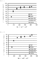
- FIG. 1 shows the relationship between the sum SE of the surface area SA of the positive electrode active material and the surface area SC of the conduction aid and the 5C charge retention rate according to Examples 1 to 8 and Comparative Examples 1 to 8 in Table 3.
- FIG. 2 shows the relationship between the sum SE of the surface area SA of the positive electrode active material and the surface area SC of the conduction aid and the 5C discharge retention rate according to Examples 1 to 8 and Comparative Examples 1 to 8 in Table 3.
- FIG. 3 shows the relationship between the sum SE of the surface area SA of the positive electrode active material and the surface area SC of the conduction aid and the amount of gas generation according to Examples 1 to 8 and Comparative Examples 1 to 8 in Table 3.
- the positive electrodes using the water-based binders for the binder according to Examples 1 to 8 have great charge/discharge rate characteristics with the 5C charge retention rate of 50% or more and 5C discharge retention rate of 70% or more shown to be almost equal to those of the positive electrodes all using polyvinylidene fluoride (PVdF) for the binder according to Comparative Examples 2 to 6.
- PVdF polyvinylidene fluoride
- the present invention is not limited to the embodiments described above, but various applications and modifications can be made within the scope of the invention, in regard to the types of the positive electrode active material, conduction aid, and binder constituting the positive electrode, the configuration of the negative electrode constituting the lithium ion secondary battery, the composition of the non-aqueous electrolytic solution, and the like.
Landscapes
- Chemical & Material Sciences (AREA)
- General Chemical & Material Sciences (AREA)
- Chemical Kinetics & Catalysis (AREA)
- Electrochemistry (AREA)
- Engineering & Computer Science (AREA)
- Inorganic Chemistry (AREA)
- Materials Engineering (AREA)
- Manufacturing & Machinery (AREA)
- Physics & Mathematics (AREA)
- Condensed Matter Physics & Semiconductors (AREA)
- General Physics & Mathematics (AREA)
- Battery Electrode And Active Subsutance (AREA)
- Secondary Cells (AREA)
Abstract
Description
- The present invention relates to a lithium ion secondary battery, and more particularly, to a positive electrode constituting a lithium ion secondary battery, and a lithium ion secondary battery using the positive electrode.
- In recent years, the reduction in size and weight for cellular phones, laptop computers, and the like has been progressed rapidly, and batteries as power sources for driving the phones, the computers, and the like have been required to have higher capacities. Further, under such circumstances, lithium ion secondary batteries have been widely used as power sources.
- Further, as a positive electrode used for such a lithium ion secondary battery, a positive electrode for a lithium ion secondary battery is proposed which uses: an active material including a compound represented by the following composition formula 1 at particle surfaces; and a water-based binder.
- Composition Formula 1: LiαMβOγ (in the formula, M represents one, or two or more metal elements selected from the group consisting of Al, Ti, Cr, Mn, Fe, Co, Ni, Cu, Zr, Nb, Mo, Ag, Ta, W, and Ir, and α, β, and γ meet 0 ≤ α ≤ 6, 1 ≤ β ≤ 5, and 0 < γ ≤ 12) (see Patent Document 1)
- In the case of the positive electrode including the configuration according to Patent Document 1, the use of the water-based binder is even supposed to make it possible to prevent oxidative decomposition of the water-based binder from being caused in the case of charge, without decreasing the capacity of the positive electrode active material due to elution of lithium in the positive electrode active material, thereby providing a positive electrode for a lithium ion secondary battery which has excellent high-temperature characteristics.
- However, in the case of Patent Document 1, the surface of the positive electrode active material is coated with the compound represented by the composition Formula 1, or the surface of the positive electrode is over-coated therewith, and there is thus the problem of failing to achieve smooth movement of lithium ions between the active material and an electrolytic solution, thereby degrading charge/discharge rate characteristics.
- In addition,
Patent Document 2 proposes a positive electrode characterized by including a spinel-type lithium-nickel-manganese composite oxide and an alginate binder. - The alginate binder for use in the positive electrode in
Patent Document 2 offers great flexibility, and can thus follow a relatively large change in the volume of the positive electrode in charge and discharge. - Furthermore, the inclusion of the alginate binder provides excellent oxidation resistance that has a significant influence on stability as a positive electrode. In addition, the alginate binder is a water-based binder, and the positive electrode thus includes no organic solvent. Therefore, the burden on the environment is reduced, and the need for an organic solvent collection system is also eliminated.
- In addition, a lithium ion secondary battery using the positive electrode has the advantages of great energy density and cycle characteristics.
- However, in
Patent Document 2, the application of the water-based binder to the positive electrode has the problem of oxidatively decomposing the water-based binder in the case of charge, as also described in the paragraph 0010 of Patent Document 1 mentioned above, and even when the alginate binder which has excellent oxidation resistance is used for the positive electrode as inPatent Document 2, there is the problem of oxidatively decomposing the alginate binder at points of contact between high-potential positive electrode active material and conduction aid and the alginate binder, thereby causing gas generation, or causing charge/discharge rate characteristic to be degraded. -
- Patent Document 1: Japanese Patent Application Laid-Open No.
2013-206742 - Patent Document 2: Japanese Patent Application Laid-Open No.
2014-96238 - The present invention is intended to solve the problem mentioned above, and an object of the present invention is to provide a positive electrode for a lithium ion secondary battery, which is capable of achieving excellent charge/discharge rate characteristics even when a water-based binder is used for a binder, and inhibiting oxidative decomposition of a non-aqueous electrolytic solution, and a lithium ion secondary battery using the positive electrode.
- In order to solve the problem mentioned above, the positive electrode for a lithium ion secondary battery according to the present invention is a positive electrode for a lithium ion secondary battery, including a positive electrode combination material including: a positive electrode active material that produces a potential of 4.5 V or higher on the basis of metal lithium; a conduction aid; and a binder, the positive electrode characterized in that the binder contains a water-based binder as its main constituent, and the sum SE of the surface area SA of the positive electrode active material in the positive electrode combination material and the surface area SC of the conduction aid therein is 90 cm2/cm2 or more and 400 cm2/cm2 or less per unit coated area of the positive electrode combination material.
- In the positive electrode for a lithium ion secondary battery according to the present invention, the water-based binder preferably includes a substance having a carboxyl group.
- The use of the positive electrode configured as mentioned above makes it possible to provide a lithium ion secondary battery which is capable of achieving a balance between great charge/discharge rate characteristics and inhibited oxidative decomposition of a non-aqueous electrolytic solution at the positive electrode surface.
- More specifically, the water-based binder having a carboxyl group has a high affinity for the surfaces of the positive electrode active material and carbon-based conduction aid, and thus achieves a greater coating effect, thereby making it possible to inhibit the oxidative decomposition of a non-aqueous electrolytic solution more reliably.
- In addition, the water-based binder preferably includes a copolymer including a carboxymethyl cellulose, a polyacrylic acid, an acrylic acid, a metal salt or ammonium salt thereof, or at least one selected from the group thereof.
- In addition, the use of the positive electrode configured as mentioned above makes it possible to provide, further reliably, a lithium ion secondary battery which is capable of achieving a balance between great charge/discharge rate characteristics and inhibited oxidative decomposition of a non-aqueous electrolytic solution at the positive electrode surface.
- It is to be noted that Na salts and K salts can be used as the metal salt.
- In addition, the sum SE is preferably 150 cm2/cm2 or more and 300 cm2/cm2 or less per unit coated area of the positive electrode combination material.
- The use of the positive electrode configured as mentioned above makes it possible to provide, further reliably, a lithium ion secondary battery which is capable of achieving a balance between great charge/discharge rate characteristics and inhibited oxidative decomposition of a non-aqueous electrolytic solution at the positive electrode surface.
- In addition, the conduction aid preferably includes non-graphitizable carbon.
- The use of the positive electrode configured as mentioned above makes it possible to provide, further reliably, a lithium ion secondary battery which is capable of inhibiting oxidative decomposition of the non-aqueous electrolytic solution.
- In addition, the positive electrode active material is preferably a spinel-type lithium-nickel-manganese oxide of a composition formula Li1+a[Mn2-a-x-yNixMy]
O 4 0 ≤ a ≤ 0.2, 0.4 ≤ x ≤ 0.6, 0 ≤ y ≤ 0.3, M represents at least one of metal elements containing Ti). - In addition, the use of the positive electrode configured as mentioned above makes it possible to achieve a lithium ion secondary battery which is capable of inhibiting oxidative decomposition of the non-aqueous electrolytic solution at a higher level.
- Furthermore, a lithium ion secondary battery according to the present invention characteristically includes the positive electrode according to the present invention, a negative electrode, and a non-aqueous electrolytic solution.
- The positive electrode for a lithium ion secondary battery according to the present invention, including the positive electrode combination material including: the positive electrode active material that produces a potential of 4.5 V or higher on the basis of metal lithium; the conduction aid; and the binder as described above, is configured such that as the binder, a binder is used which contains a water-based binder as its main constituent, and the sum SE of the surface area SA of the positive electrode active material in the positive electrode combination material and the surface area SC of the conduction aid therein is kept within the range of 90 cm2/cm2 or more and 400 cm2/cm2 or less per unit coated area of the positive electrode combination material. Thus, the application of the positive electrode configured as mentioned above to a lithium ion secondary battery makes it possible to provide a lithium ion secondary battery which is capable of exhibiting great charge/discharge rate characteristics, and inhibiting oxidative decomposition of a non-aqueous electrolytic solution at the positive electrode surface, thereby suppressing cell bulge due to gas generation.
- More specifically, the water-based binder is more effective in coating the positive electrode active material and the conduction aid, as compared with solvent-based binders such as polyvinylidene fluoride, thereby making it possible to reduce the area of contact between the active material or conduction aid and an electrolytic solution, and thus inhibit oxidative decomposition of a non-aqueous electrolytic solution at the surface of the positive electrode combination material.
- It is to be noted that in the positive electrode for a lithium ion secondary battery according to the present invention, when the sum SE of the surface area SA of the positive electrode active material and the surface area SC of the conduction aid per unit coated area of the positive electrode combination material is less than 90 cm2/cm2, the insufficient area of contact between the positive electrode combination material and the non-aqueous electrolytic solution unfavorably fails to cause an electrochemical reaction to proceed smoothly at the interface between the positive electrode combination material and the non-aqueous electrolytic solution, thereby degrading charge/discharge rate characteristics.
- Alternatively, when the sum SE of the surface area SA of the positive electrode active material and the surface area SC of the conduction aid per unit coated area of the positive electrode combination material exceeds 400 cm2/cm2, the excessively increased area of contact between the positive electrode combination material and the non-aqueous electrolytic solution unfavorably causes oxidative decomposition of the non-aqueous electrolytic solution to proceed significantly at the surface of the positive electrode combination material, thereby generating a large amount of gas.
- In addition, the lithium ion secondary battery according to the present invention includes the above-mentioned positive electrode according to the present invention, the negative electrode, and the non-aqueous electrolytic solution, thus making it possible to provide a lithium ion secondary battery which achieves a balance between great charge/discharge rate characteristics and inhibited oxidative decomposition of the non-aqueous electrolytic solution at the positive electrode surface, and has a high operating voltage and a high energy density.
- It is to be noted that in accordance with the present invention, the surface area SA of the positive electrode active material [cm2/cm2] refers to a value obtained from the formula (1) :

- In addition, the surface area SC of the conduction aid [cm2/cm2] refers to a value obtained from the formula (2):

- In addition, the sum SE of the surface area SA of the positive electrode active material in the positive electrode combination material and the surface area SC of the conduction aid therein refers to a value obtained from the formula (3):

-
-
FIG. 1 is a diagram showing the relationship between the sum SE of the surface area SA of the positive electrode active material and the surface area SC of the conduction aid and the 5C charge retention rate according to Examples 1 to 8 and Comparative Examples 1 to 8 in Table 3. -
FIG. 2 is a diagram showing the relationship between the sum SE of the surface area SA of the positive electrode active material and the surface area SC of the conduction aid and the 5C discharge retention rate according to Examples 1 to 8 and Comparative Examples 1 to 8 in Table 3. -
FIG. 3 is a diagram showing the relationship between the sum SE of the surface area SA of the positive electrode active material and the surface area SC of the conduction aid and the amount of gas generation according to Examples 1 to 8 and Comparative Examples 1 to 8 in Table 3. - A positive electrode for a lithium ion secondary battery according to an embodiment of the present invention, and an embodiment of a lithium ion secondary battery using the positive electrode will be described below.
- The positive electrode for a lithium ion secondary battery according to an embodiment of the present invention includes: a positive electrode active material that produces a potential of 4.5 V or higher on the basis of metal lithium, a conduction aid, and a binder.
- In the positive electrode for a lithium ion secondary battery, the positive electrode active material that produces a potential of 4.5 V or higher on the basis of metal lithium is not particularly limited, but spinel-type lithium-manganese oxides such as LiNi0.5Mn1.5O4 and LiCoMnO4, inverse-spinel type lithium-vanadium oxides such as LiNiVO4, polyanion compounds such as LiCoPO4 and LiNiPO4 can be used.
- Among these compounds, from the standpoints of charge/discharge stability and charge/discharge capacity at a potential of 4.5 V or higher, the positive electrode active material is preferably a spinel-type lithium-nickel-manganese oxide. Furthermore, the positive electrode active material is more preferably a spinel-type lithium-nickel-manganese oxide represented by the composition formula Li1+a[Mn2-a-x-yNixMy]O4 (0 ≤ a ≤ 0.3, 0 ≤ x ≤ 0.6, 0 ≤ y ≤ 0.3, M represents at least one of metal elements containing Ti).
- In the positive electrode for a lithium ion secondary battery, the conduction aid is used.
- Carbon black such as acetylene black, thermal black, Ketjen Black, and furnace black, non-graphitizable carbon, vapor-grown carbon fibers (VGCF), carbon tubes, graphite, graphitizable carbon, graphene, metal powders, and the like can be used as the conduction aid. Among the foregoing, the non-graphitizable carbon is preferably included from the perspective of charge/discharge rate characteristics and suppression of cell bulge due to gas generation.
- In the positive electrode for a lithium ion secondary battery, a water-based binder is used as the binder.
- Further, as the water-based binder, a binder can be preferably used which includes a copolymer including a carboxymethyl cellulose, a polyacrylic acid, an acrylic acid, a metal salt or ammonium salt thereof, or at least one selected from the group thereof.
- The foregoing positive electrode active material, conduction aid, and binder are used to prepare the positive electrode for a lithium ion secondary battery according to an embodiment of the present invention.
- First, the positive electrode active material, the conduction aid, and the binder are mixed in predetermined proportions. A solvent that dissolves the binder is added thereto, and mixed therewith, thereby providing a slurry form. This slurry is applied onto a current collector through the control of the application amount such that the sum SE of the surface area SA of the positive electrode active material and the surface area SC of the conduction aid in the positive electrode combination material is 90 cm2/cm2 or more and 400 cm2/cm2 or less per unit coated area of the positive electrode combination material, and dried, thereby forming a positive electrode combination material layer. If necessary, pressure forming such as pressing, and cutting are carried out, thereby preparing the positive electrode.
- The current collector of the positive electrode is not particularly limited, but for example, foil, an expanded metal, a punching metal, a mesh, or the like of aluminum, stainless steel, titanium, nickel, or alloy thereof can be used, and in particular, aluminum foil is preferred.
- A lithium ion secondary battery according to an embodiment of the present invention as described below can be prepared with the use of the thus prepared positive electrode according to an embodiment of the present invention, a negative electrode, and a non-aqueous electrolytic solution.
- The following can be used as the negative electrode for use in the lithium ion secondary battery.
- It is possible to use any negative electrode active material without any particular limitation, as long as the material electrochemically reacts with lithium ions, and examples of the material include carbon materials such as natural graphite, artificial graphite, graphitizable carbon, and non-graphitizable carbon, alloy-based negative electrodes such as silicon and tin, oxides such as lithium titanate, titanium oxide, silicon oxide, and tin oxide, and metal lithium. One of these materials may be used alone, or two or more thereof may be used in combination.
- In the case of preparing the negative electrode, first, the negative electrode active material mentioned above, the same binder as in the case of the previously described positive electrode, a solvent that dissolves the binder, and if necessary, the same conduction aids as in the case of the positive electrode are added and mixed, thereby providing a slurry form. This slurry is applied onto a current collector, and dried to form a negative electrode combination material layer. If necessary, pressure molding such as pressing, and cutting are carried out, thereby preparing the negative electrode.
- The current collector used for the negative electrode is not particularly limited, but for example, foil, an expanded metal, a punching metal, a mesh, or the like of copper, stainless steel, titanium, nickel, or alloy thereof can be used. In particular, copper foil is preferably used.
- A solution including an electrolyte salt and an organic solvent is used as the non-aqueous electrolytic solution for use in the lithium ion secondary battery according to this embodiment.
- In addition, the electrolyte salt is also not particularly limited, but it is possible to use, for example, LiPF6, LiClO4, LiBF4, LiCF3SO3, Li(CF3SO2)2N, Li(C2F5SO2)2N, Li(CF3)2N, and LiB(CN)4, and one of these salts may be used alone, or two or more thereof may be used in combination. The electrolyte salt concentration in the non-aqueous electrolytic solution is desirably 0.3 to 4 mol/L.
- In addition, the organic solvent is also not particularly limited, but carbonate-type solvents, lactone-type solvents, sulfone-type solvents, nitrile-type solvents, ester-type solvents, ether-type solvents, and the like can be used. In addition, for the purpose of improving the oxidation resistance of these solvents, the solvents partially substituted with an element that is high in electronegativity, such as fluorine, may be also used. One of these solvents may be used alone, or two or more thereof may be used in combination.
- In addition, for the purpose of improving the oxidation resistance of the non-aqueous electrolytic solution, or for the purpose of forming, on the surface of the positive electrode or the negative electrode, a protective film that inhibits the decomposition of the non-aqueous electrolytic solution, various types of additives may be added, if necessary. The additives include additives that dissolve in organic solvents or also serve as an organic solvents, e.g., carbonate-type compounds such as vinylene carbonate and fluoro-ethylene carbonate, sulfur-type compounds such as 1,3-propanesultone, and lithium salts such as lithium bis(oxalato)borate.
- The lithium ion secondary battery according to an embodiment of the present invention can be prepared by using the positive electrode, negative electrode, and non-aqueous electrolytic solution described above.
- Features of the present invention will be described in more detail below with reference to more specific embodiments of the present invention.
- A lithium carbonate (Li2CO3) as a lithium-containing raw material, a nickel hydroxide (Ni(OH)2) as a nickel-containing raw material, trimanganese tetraoxide (Mn3O4) as a manganese-containing raw material, and an anatase-type titanium oxide (TiO2) as a titanium-containing raw material were prepared, and these raw materials were weighed so as to meet a predetermined composition ratio.
- The weighed raw materials were mixed with a ball mill with the use of water for a solvent and zirconia balls of 5 mm in diameter, thereby preparing slurry. This slurry was subjected to spray drying, thereby providing a dried powder.
- Then, the dried powder obtained was put in a sagger containing alumina as its main constituent, and subjected to firing for 10 hours at a temperature of 1050°C in the atmosphere, and then firing for 20 hours at a temperature of 700°C in the atmosphere. This fired product was subjected to grinding in a mortar, thereby providing a positive electrode active material.
- This positive electrode active material was subjected to composition analysis by inductively-coupled plasma atomic emission spectroscopy (ICP-AES), and the specific surface area of the material was measured by a BET method. Furthermore, the average particle size (D50) was measured with a laser diffraction-scattering type particle size distribution meter.
- The results are shown in Table 1.
[Table 1] Composition Specific Surface Area (m2/g) Average Particle Size (µm) Positive Electrode Active Material Li1.1[Ni0.45Mn1.35Ti0.2]O4 0.30 17 - Carbon black and non-graphitizable carbon were prepared as the conduction aid.
- Then, the specific surface areas of the carbon black and non-graphitizable carbon were checked by the same method as in the case of the positive electrode active material described above. In addition, the carbon black was observed with an electron microscope, thereby checking particle sizes, and the arithmetic mean was obtained, thereby providing the average particle sizes. Furthermore, the average particle size (D50) of the non-graphitizable carbon was measured with a laser diffraction-scattering type particle size distribution meter.
- The results are shown in Table 2.
[Table 2] Specific Surface Area (m2/g) Average Particle Size (nm) Carbon Black 91 28 Non-Graphitizable Carbon 1.9 15 - In this embodiment, a polyvinylidene fluoride (PVdF) as an organic solvent-based binder, a sodium polyacrylate (PAANa) as a water-based binder, a copolymer (PAANa-PAN) of sodium acrylate and acrylonitrile, a copolymer (PAANa-PVA) of sodium acrylate and vinyl alcohol, and carboxymethyl cellulose sodium (CMCNa) were used as the binder.
- It is to be noted that the polyvinylidene fluoride (PVdF) is a binder for comparison, which fails to meet the requirements of the present invention.
- The positive electrode active material, carbon black, non-graphitizable carbon described above, a solution of the above-described binder dissolved were mixed in ratio by weight as shown in Table 3, thereby preparing positive electrode combination material slurry.
- The binder dissolved in a solvent in advance was used in a solution state, and N-methyl-2-pyrrolidone was used for the solvent in the case of polyvinylidene fluoride (PVdF), whereas water was used for the solvent in the case of the binder other than polyvinylidene fluoride (PVdF).
- Then, the positive electrode combination material slurry was applied to one or both sides of aluminum foil of 15 µm in thickness as a positive electrode current collectors, such that the weight per unit coated area of the positive electrode active material included in the dried positive electrode combination material was approximately 7.2 mg/cm2 per side. Then, the slurry was dried at a temperature of 140°C when the binder was polyvinylidene fluoride (PVdF), or 80°C in the case other than polyvinylidene fluoride (PVdF), and thereafter, subjected to pressing by roll press such that the positive electrode combination material density fell within the range of 2.7 to 3.0 g/cm3, thereby preparing positive electrodes (samples) according to Examples 1 to 8 and positive electrodes (samples) according to Comparative Examples 1 to 8.
- Then, the surface area SA [cm2/cm2] of positive electrode active material was obtained from the following formula with the use of the weight (mg/cm2) for each material included per unit coated area of the positive electrode combination material, and the values of the specific surface areas (m2/g) of the respective materials, obtained by a BET method.

- In addition, the surface area SC of the conduction aid [cm2/cm2] was obtained from the following formula.

- In addition, the sum SE of the surface area SA of the positive electrode active material in the positive electrode combination material and the surface area SC of the conduction aid therein was obtained from the following formula.

- In this regard, the area coated with the positive electrode combination material refers to the area of a part with the positive electrode combination material applied to the surface of the positive electrode current collector, and for example, the area coated with the positive electrode combination material is 10 cm2 when the positive electrode combination material is applied entirely to one side of the 10 cm2 positive electrode current collector, whereas the area coated with the positive electrode combination material is 20 cm2 when the positive electrode combination material is applied entirely to both sides thereof.
- Graphite as a negative electrode active material and polyvinylidene fluoride as a binder were mixed in proportions at 92.5 : 7.5 in ratio by weight, and N-methyl-2-pyrrolidone was added to the mixture, thereby preparing negative electrode combination material slurry.
- This negative electrode combination material slurry was applied to both sides of electrolytic copper foil of 10 µm in thickness as a negative electrode current collector, such that the weight per unit coated area of the negative electrode active material included in the dried negative electrode combination material was approximately 3.5 mg/cm2 per side.
- Then, the negative electrode combination material slurry applied was dried at a temperature of 140°C, and thereafter, subjected to pressing by roll press such that the negative electrode combination material density fell within the range of 1.0 to 1.3 g/cm3. The pressed negative electrode was cut out into a strip shape of 44 mm x 460 mm, and a nickel tab is welded thereto, thereby preparing a negative electrode for a wound battery.
- The positive electrode with the positive electrode combination material applied to one side was subjected to punching into a disc of 12 mm in diameter as a positive electrode for a coin battery.
- Disc-like metal lithium of 15 mm in diameter was attached to a stainless-steel current collecting plate of 15 mm in diameter as a negative electrode for a coin battery.
- For a separator, a glass filter (Trade Name "ADVANTEC GA-100") of 16 mm in diameter was used.
- For an electrolytic solution, 1M LiPF6 ethylene carbonate (EC) : ethylmethyl carbonate (EMC) = 1 : 3 (volume ratio) was used.
- Then, the above-mentioned positive electrode for a coin battery, negative electrode for a coin battery, separator, and electrolytic solution were used to prepare a coin battery.
- It is to be noted that this coin battery is a sample prepared to carry out a charge/discharge rate test as described later and check the 5C charge retention rate [%] and the 5C discharge retention rate [%].
- The positive electrode with the positive electrode combination material applied to both sides was cut out into a strip of 42 mm x 370 mm, with an aluminum tab welded thereto, thereby preparing a positive electrode for a wound battery.
- For a separator, a polyethylene microporous membrane of 15 µm in thickness was used.
- Then, the above-mentioned positive electrode for a wound battery, the negative electrode for a wound battery, prepared in accordance with the section [5], and the separator were wound with a winding machine, thereby preparing a wound body. For an electrolytic solution, 1M LiPF6 EC : EMC = 1 : 3 (volume ratio) was used. For an outer package, an aluminum laminate was used.
- Then, the wound body, the electrolytic solution, and the outer package were used to prepare a wound battery (wound lithium ion secondary battery).
- It is to be noted that this wound battery is a sample prepared to carry out a constant-voltage charging test as described later and measure the amount of gas generation.
- For the coin battery prepared in the way described above, the positive electrode was subjected to the charge/discharge rate test. In a thermostatic bath at 25°C, 3 cycles of charge/discharge were carried out at a current value of 0.2 mA/cm2 in a voltage range of 3.0 to 5.0 V. The charge capacity and discharge capacity of the third cycle were respectively regarded as "0.2C charge capacity" and "0.2C discharge capacity". Thereafter, the charge capacity in the case of charging up to 5.0 V at a current value of 5.1 mA/cm2 was regarded as a "5C charge capacity". Thereafter, in the case of leaving the open circuit for 10 minutes, charging up to 5.0 V at a current value of 0.20 mA/cm2 and discharging down to 3.0 V at a current value of 5.1 mA/cm2, the discharge capacity was regarded as a "5C discharge capacity". The "5C charge retention rate" was calculated from the following formula (4), whereas the "5C discharge retention rate" was calculated from the following formula.


- The wound battery prepared in the way described above was subjected to the constant-voltage charging test, and the amount of gas generation was measured from the volume change of the cell between before and after the test.
- In a thermostatic bath at 45°C, the battery was subjected to constant-voltage charging for 168 hours at 4.9 V, immediately after charging up to 4.9 V at a current value of 50 mA. After the charging, the battery was discharged down to 3.0 V at a current value of 50 mA. The volumes of the cell before and after the constant-voltage charging test were measured by an Archimedes method, and the amount of gas generation was calculated from the following formula.

- Table 3 shows the materials used for the positive electrode combination material, and the ratios of the materials by weight, SE, the 5C discharge capacity, the 5C charge retention rate, and the amount of gas generation in the case of using the above-described positive electrode active material (see Table 1) for the positive electrode active material.
- It is to be noted that as for the data on the positive electrodes according to Examples 1 to 8 in Table 3 and the positive electrodes according to Comparative Examples 1 to 8 in Table 3, the 5C charge retention rate [%] and the 5C discharge retention rate [%] refer to data obtained with, as samples, coin batteries prepared in the way described above, and the amount of gas generation refers to data obtained with, as samples, wound batteries as described above, prepared with the use of positive electrodes under the same conditions as for the above-described coin batteries checked on the 5C charge retention rates and the 5C discharge retention rates.
[Table 3] Positive Electrode Active Material in Ratio by Weight (%) Carbon Black in Ratio by Weight (%) Non-Graphitizable Carbon in Ratio by Weight (%) Binder SE (cm2/cm2) 5C Charge Retention Rate (%) 5C Discharge Retention Rate (%) Amount of Gas Generation (mL) Positive Electrode Active Material Carbon Black Non-Graphitizable Carbon Type Ratio by Weight (%) Comparative Example 1 6 0 PVdF 412 85 98 40 Comparative Example 2 5.5 0.5 380 85 94 37 Comparative Example 3 4 2 284 85 91 33 Comparative Example 4 3 3 220 83 91 27 Comparative Example 5 2 4 156 77 86 24 Comparative Example 6 1 5 91 63 70 18 Comparative Example 7 88 6 0 PAANa 6 412 84 99 43 Example 1 5.5 0.5 380 81 93 32 Example 2 4 2 284 81 90 25 Example 3 3 3 220 79 90 19 Example 4 2 4 156 73 85 16 Example 5 1 5 91 59 70 16 Comparative Example 8 0.5 5.5 59 33 37 15 Example 6 3 3 PAANa-PAN 220 80 87 10 Example 7 3 3 PAANa-PVA 220 76 89 18 Example 8 3 3 CMCNa 220 78 85 18 - In addition,
FIG. 1 shows the relationship between the sum SE of the surface area SA of the positive electrode active material and the surface area SC of the conduction aid and the 5C charge retention rate according to Examples 1 to 8 and Comparative Examples 1 to 8 in Table 3. -
FIG. 2 shows the relationship between the sum SE of the surface area SA of the positive electrode active material and the surface area SC of the conduction aid and the 5C discharge retention rate according to Examples 1 to 8 and Comparative Examples 1 to 8 in Table 3. - Furthermore,
FIG. 3 shows the relationship between the sum SE of the surface area SA of the positive electrode active material and the surface area SC of the conduction aid and the amount of gas generation according to Examples 1 to 8 and Comparative Examples 1 to 8 in Table 3. - As shown in Table 3 and
FIGS. 1 and 2 , it has been confirmed that when the sum SE of the surface area SA of the positive electrode active material and the surface area SC of the conduction aid falls within the range of 90 cm2/cm2 or more and 400 cm2/cm2 or less, the positive electrodes using the water-based binders for the binder according to Examples 1 to 8 have great charge/discharge rate characteristics with the 5C charge retention rate of 50% or more and 5C discharge retention rate of 70% or more shown to be almost equal to those of the positive electrodes all using polyvinylidene fluoride (PVdF) for the binder according to Comparative Examples 2 to 6. - In addition, it has been confirmed that when the sum SE of the surface area SA of the positive electrode active material and the surface area SC of the conduction aid is 150 cm2/cm2 or more as in Examples 1 to 4, 6, and 7, positive electrodes are achieved which have greater charge/discharge rate characteristics with the 5C charge retention rate of 70% or more and 5C discharge retention rate of 80% or more shown.
- On the other hand, it has been confirmed that the positive electrode according to Comparative Example 8 where the sum SE of the surface area SA of the positive electrode active material and the surface area SC of the conduction aid is less than 90 cm2/cm2 has charge/discharge rate characteristics degraded, with the 5C charge retention rate of 33%.
- 1 In addition, as shown in Table 3 and
FIG. 3 , it has been confirmed that when the sum SE of the surface area SA of the positive electrode active material and the surface area SC of the conduction aid falls within the range of 90 cm2/cm2 or more and 400 cm2/cm2 or less, in comparison between the positive electrodes using sodium polyacrylate (PAANa) for the binder according to Examples 1 to 5 and the positive electrodes using polyvinylidene fluoride (PVdF) for the binder according to Comparative Examples 2 to 6 with SE of the same value, the oxidative decomposition of the non-aqueous electrolytic solution at the positive electrode surfaces is inhibited, with smaller amounts of gas generation in each case of using the sodium polyacrylate (PAANa) for the binder. In addition, it has been confirmed that the positive electrodes using the other water-based binders according to Examples 6 to 8 also achieve similar effects. - Furthermore, it has been confirmed that as long as the sum SE of the surface area SA of the positive electrode active material and the surface area SC of the conduction aid is 300 cm2/cm2 or less as in Examples 2 to 8, the oxidative decomposition of the non-aqueous electrolytic solution at the positive electrode surfaces is further reliably inhibited, with the amount of gas generation reduced to 25 mL or less.
- It has been confirmed that the positive electrode according to Comparative Example 7 (using sodium polyacrylate (PAANa) for the binder) where the sum SE of the surface area SA of the positive electrode active material and the surface area SC of the conduction aid is more than 400 cm2/cm2 has an increased amount of gas generation, as compared with Comparative Example 1 (using polyvinylidene fluoride (PVdF) for the binder) where the sum SE of the surface area SA of the positive electrode active material and the surface area SC of the conduction aid has the same value. This is believed to be because the increased sum SE of the surface area SA of the positive electrode active material and the surface area SC of the conduction aid increased the area of contact between the positive electrode combination material and the binder, thereby causing the oxidative decomposition of the water-based binder to proceed, and thus increasing the amount of gas generation.
- It is to be noted that the present invention is not limited to the embodiments described above, but various applications and modifications can be made within the scope of the invention, in regard to the types of the positive electrode active material, conduction aid, and binder constituting the positive electrode, the configuration of the negative electrode constituting the lithium ion secondary battery, the composition of the non-aqueous electrolytic solution, and the like.
Claims (7)
- A positive electrode for a lithium ion secondary battery, comprising a positive electrode combination material comprising: a positive electrode active material that produces a potential of 4.5 V or higher on the basis of metal lithium; a conduction aid; and a binder, wherein the binder contains a water-based binder as its main constituent, and a sum SE of a surface area SA of the positive electrode active material in the positive electrode combination material and a surface area SC of the conduction aid therein is 90 cm2/cm2 or more and 400 cm2/cm2 or less per unit coated area of the positive electrode combination material.
- The positive electrode for a lithium ion secondary battery according to claim 1, wherein the water-based binder comprises a substance having a carboxyl group.
- The positive electrode for a lithium ion secondary battery according to one of claims 1 and 2, wherein the water-based binder comprises a copolymer comprising a carboxymethyl cellulose, a polyacrylic acid, an acrylic acid, a metal salt or ammonium salt thereof, or at least one selected from the group thereof.
- The positive electrode for a lithium ion secondary battery according to claims 1 to 3, wherein the sum SE is 150 cm2/cm2 or more and 300 cm2/cm2 or less per unit coated area of the positive electrode combination material.
- The positive electrode for a lithium ion secondary battery according to claims 1 to 4, wherein the conduction aid comprises non-graphitizable carbon.
- The positive electrode for a lithium ion secondary battery according to claims 1 to 5, wherein the positive electrode active material is a spinel-type lithium-nickel-manganese oxide of a composition formula Li1+a [Mn2-a-x-yNixMy]O4 0 ≤ a ≤ 0.2, 0.4 ≤ x ≤ 0.6, 0 ≤ y ≤ 0.3, M represents at least one of metal elements containing Ti).
- A lithium ion secondary battery comprising the positive electrode according to claims 1 to 6, a negative electrode, and a non-aqueous electrolytic solution.
Applications Claiming Priority (2)
| Application Number | Priority Date | Filing Date | Title |
|---|---|---|---|
| JP2014233552 | 2014-11-18 | ||
| PCT/JP2015/080928 WO2016080181A1 (en) | 2014-11-18 | 2015-11-02 | Positive electrode for lithium ion secondary batteries, and lithium ion secondary battery using same |
Publications (2)
| Publication Number | Publication Date |
|---|---|
| EP3223343A1 true EP3223343A1 (en) | 2017-09-27 |
| EP3223343A4 EP3223343A4 (en) | 2018-05-16 |
Family
ID=56013734
Family Applications (1)
| Application Number | Title | Priority Date | Filing Date |
|---|---|---|---|
| EP15860089.0A Withdrawn EP3223343A4 (en) | 2014-11-18 | 2015-11-02 | Positive electrode for lithium ion secondary batteries, and lithium ion secondary battery using same |
Country Status (5)
| Country | Link |
|---|---|
| US (1) | US10873085B2 (en) |
| EP (1) | EP3223343A4 (en) |
| JP (1) | JP6308307B2 (en) |
| CN (1) | CN107155381B (en) |
| WO (1) | WO2016080181A1 (en) |
Families Citing this family (3)
| Publication number | Priority date | Publication date | Assignee | Title |
|---|---|---|---|---|
| US20200303744A1 (en) * | 2016-03-30 | 2020-09-24 | Nec Energy Devices, Ltd. | Electrode and method for manufacturing the same, and secondary battery |
| JP6898731B2 (en) * | 2016-12-27 | 2021-07-07 | 三井金属鉱業株式会社 | Positive electrode for lithium secondary battery |
| CN117293315A (en) * | 2023-09-26 | 2023-12-26 | 绿能纤材(重庆)科技有限公司 | Positive electrode conductive paste containing carboxymethyl cellulose salt, preparation method of positive electrode conductive paste, positive electrode plate and lithium ion battery |
Family Cites Families (15)
| Publication number | Priority date | Publication date | Assignee | Title |
|---|---|---|---|---|
| KR100423030B1 (en) * | 2000-03-13 | 2004-03-12 | 캐논 가부시끼가이샤 | Process for producing an electrode material for a rechargeable lithium battery, an electrode structural body for a rechargeable lithium battery, process for producing said electrode structural body, a rechargeable lithium battery in which said electrode structural body is used, and a process for producing said rechargeable lithium battery |
| CN100530779C (en) * | 2002-10-18 | 2009-08-19 | 北京圣比和科技有限公司 | Preparing method for spinel potassium manganate as lithium ion battery anode of electric vehicle |
| FR2890241B1 (en) * | 2005-08-25 | 2009-05-22 | Commissariat Energie Atomique | HIGH SPEED SPINELLE STRUCTURE POSITIVE ELECTRODE MATERIAL BASED ON NICKEL AND MANGANESE FOR LITHIUM ACCUMULATORS |
| JP2007184127A (en) | 2006-01-05 | 2007-07-19 | Nissan Motor Co Ltd | Secondary battery, electrode therefor, and manufacturing method thereof |
| JP5253905B2 (en) * | 2008-06-30 | 2013-07-31 | パナソニック株式会社 | Non-aqueous electrolyte and non-aqueous electrolyte secondary battery |
| JP5510704B2 (en) * | 2009-09-10 | 2014-06-04 | トヨタ自動車株式会社 | Secondary battery and method of manufacturing the battery |
| JP5737513B2 (en) * | 2011-07-07 | 2015-06-17 | 戸田工業株式会社 | Positive electrode active material powder for non-aqueous electrolyte secondary battery, method for producing the same, and non-aqueous electrolyte secondary battery |
| PL2693534T3 (en) | 2011-03-31 | 2022-10-31 | Toda Kogyo Corp. | Manganese-nickel composite oxide particle powder, production method therefor, positive-electrode active material particle powder for nonaqueous electrolyte secondary batteries, production method therefor, and nonaqueous electrolyte secondary battery |
| KR20130081055A (en) * | 2012-01-06 | 2013-07-16 | 삼성에스디아이 주식회사 | Positive electrode material for lithium battery, positive material prepared from the material, and lithium battery including the positive electrode |
| JP5936406B2 (en) | 2012-03-26 | 2016-06-22 | オートモーティブエナジーサプライ株式会社 | Lithium ion secondary battery |
| JP5999683B2 (en) | 2012-03-28 | 2016-09-28 | 国立研究開発法人産業技術総合研究所 | Positive electrode for lithium ion secondary battery excellent in high temperature characteristics, lithium ion secondary battery equipped with the positive electrode, and electrical equipment using the secondary battery |
| JP6068819B2 (en) * | 2012-04-16 | 2017-01-25 | シャープ株式会社 | Method for producing positive electrode for non-aqueous electrolyte secondary battery |
| JP2013222686A (en) * | 2012-04-19 | 2013-10-28 | Sharp Corp | Positive electrode for nonaqueous electrolyte secondary battery, and nonaqueous electrolyte secondary battery |
| CN104641495A (en) * | 2012-08-08 | 2015-05-20 | 通用汽车环球科技运作有限责任公司 | Composite cathode materials with controlled irreversible capacity loss for lithium ion batteries |
| JP2014096238A (en) | 2012-11-08 | 2014-05-22 | Fuji Heavy Ind Ltd | Process of manufacturing positive electrode for power storage device and positive electrode |
-
2015
- 2015-11-02 JP JP2016560140A patent/JP6308307B2/en active Active
- 2015-11-02 EP EP15860089.0A patent/EP3223343A4/en not_active Withdrawn
- 2015-11-02 WO PCT/JP2015/080928 patent/WO2016080181A1/en active Application Filing
- 2015-11-02 CN CN201580061029.3A patent/CN107155381B/en active Active
-
2017
- 2017-05-10 US US15/591,426 patent/US10873085B2/en active Active
Also Published As
| Publication number | Publication date |
|---|---|
| US10873085B2 (en) | 2020-12-22 |
| CN107155381B (en) | 2020-05-15 |
| EP3223343A4 (en) | 2018-05-16 |
| JPWO2016080181A1 (en) | 2017-06-29 |
| CN107155381A (en) | 2017-09-12 |
| US20170331113A1 (en) | 2017-11-16 |
| JP6308307B2 (en) | 2018-04-11 |
| WO2016080181A1 (en) | 2016-05-26 |
Similar Documents
| Publication | Publication Date | Title |
|---|---|---|
| EP1734601B1 (en) | Nonaqueous electrolyte secondary battery | |
| JP4785482B2 (en) | Nonaqueous electrolyte secondary battery | |
| JP5399188B2 (en) | Nonaqueous electrolyte secondary battery | |
| JP4721729B2 (en) | Nonaqueous electrolyte secondary battery | |
| EP3930052A1 (en) | Low gas-producing high capacity ternary positive electrode material | |
| JP4841133B2 (en) | Nonaqueous electrolyte secondary battery | |
| EP2685532A1 (en) | Nonaqueous electrolyte secondary battery | |
| JP4798964B2 (en) | Nonaqueous electrolyte secondary battery | |
| JP6493409B2 (en) | Non-aqueous electrolyte secondary battery | |
| KR20160098315A (en) | Positive-electrode active material powder, positive electrode containing positive-electrode active material powder, and secondary battery | |
| US20140110641A1 (en) | Method for producing active material particles for lithium ion secondary battery, electrode and lithium ion secondary battery | |
| EP2712009B1 (en) | Bimodal-type anode active material and lithium secondary battery including same | |
| JP5036121B2 (en) | Nonaqueous electrolyte secondary battery | |
| EP4187639A1 (en) | Positive electrode material and battery | |
| JP2005050779A (en) | Nonaqueous electrolytic solution secondary battery | |
| WO2016031147A1 (en) | Positive-electrode active material for nonaqueous-electrolyte secondary battery | |
| US10177370B2 (en) | Positive electrode for lithium ion secondary battery and lithium ion secondary battery using the same | |
| US10873085B2 (en) | Positive electrode for lithium ion secondary battery and lithium ion secondary battery using the same | |
| WO2016103592A1 (en) | Positive electrode active material and nonaqueous electrolyte secondary battery | |
| JP2009266791A (en) | Nonaqueous electrolyte secondary battery | |
| EP3223345B1 (en) | Positive electrode active material particle powder for non-aqueous electrolyte secondary battery, method for manufacturing same, and non-aqueous electrolyte secondary battery | |
| CN112424984A (en) | Rechargeable lithium ion battery with improved life characteristics | |
| JP2010177207A (en) | Non aqueous electrolyte secondary battery | |
| JP2005339886A (en) | Nonaqueous electrolyte secondary battery | |
| JP2012089366A (en) | Negative active material for lithium ion secondary battery, lithium ion secondary battery using the same, and manufacturing method of negative active material for lithium ion secondary battery |
Legal Events
| Date | Code | Title | Description |
|---|---|---|---|
| PUAI | Public reference made under article 153(3) epc to a published international application that has entered the european phase |
Free format text: ORIGINAL CODE: 0009012 |
|
| 17P | Request for examination filed |
Effective date: 20170427 |
|
| AK | Designated contracting states |
Kind code of ref document: A1 Designated state(s): AL AT BE BG CH CY CZ DE DK EE ES FI FR GB GR HR HU IE IS IT LI LT LU LV MC MK MT NL NO PL PT RO RS SE SI SK SM TR |
|
| AX | Request for extension of the european patent |
Extension state: BA ME |
|
| DAV | Request for validation of the european patent (deleted) | ||
| DAX | Request for extension of the european patent (deleted) | ||
| A4 | Supplementary search report drawn up and despatched |
Effective date: 20180418 |
|
| RIC1 | Information provided on ipc code assigned before grant |
Ipc: H01M 4/525 20100101ALI20180412BHEP Ipc: H01M 4/62 20060101ALI20180412BHEP Ipc: H01M 4/505 20100101ALI20180412BHEP Ipc: H01M 4/13 20100101AFI20180412BHEP Ipc: H01M 10/0566 20100101ALI20180412BHEP Ipc: H01M 4/131 20100101ALI20180412BHEP |
|
| GRAP | Despatch of communication of intention to grant a patent |
Free format text: ORIGINAL CODE: EPIDOSNIGR1 |
|
| INTG | Intention to grant announced |
Effective date: 20190214 |
|
| STAA | Information on the status of an ep patent application or granted ep patent |
Free format text: STATUS: THE APPLICATION IS DEEMED TO BE WITHDRAWN |
|
| 18D | Application deemed to be withdrawn |
Effective date: 20190625 |