EP3223326A1 - Display apparatus - Google Patents
Display apparatus Download PDFInfo
- Publication number
- EP3223326A1 EP3223326A1 EP17160858.1A EP17160858A EP3223326A1 EP 3223326 A1 EP3223326 A1 EP 3223326A1 EP 17160858 A EP17160858 A EP 17160858A EP 3223326 A1 EP3223326 A1 EP 3223326A1
- Authority
- EP
- European Patent Office
- Prior art keywords
- layer
- electrode
- display
- islands
- display apparatus
- Prior art date
- Legal status (The legal status is an assumption and is not a legal conclusion. Google has not performed a legal analysis and makes no representation as to the accuracy of the status listed.)
- Granted
Links
- 239000000758 substrate Substances 0.000 claims abstract description 79
- 238000005538 encapsulation Methods 0.000 claims abstract description 75
- 238000002161 passivation Methods 0.000 claims abstract description 54
- 239000010409 thin film Substances 0.000 claims abstract description 49
- 230000000149 penetrating effect Effects 0.000 claims abstract description 6
- 239000010410 layer Substances 0.000 claims description 460
- 239000000463 material Substances 0.000 claims description 43
- 239000012044 organic layer Substances 0.000 claims description 35
- 239000010408 film Substances 0.000 claims description 34
- 239000011521 glass Substances 0.000 claims description 13
- 229910052814 silicon oxide Inorganic materials 0.000 claims description 13
- VYPSYNLAJGMNEJ-UHFFFAOYSA-N Silicium dioxide Chemical compound O=[Si]=O VYPSYNLAJGMNEJ-UHFFFAOYSA-N 0.000 claims description 11
- OKTJSMMVPCPJKN-UHFFFAOYSA-N Carbon Chemical compound [C] OKTJSMMVPCPJKN-UHFFFAOYSA-N 0.000 claims description 7
- 229910052799 carbon Inorganic materials 0.000 claims description 7
- 230000001154 acute effect Effects 0.000 claims description 5
- GCFDVEHYSAUQGL-UHFFFAOYSA-J fluoro-dioxido-oxo-$l^{5}-phosphane;tin(4+) Chemical class [Sn+4].[O-]P([O-])(F)=O.[O-]P([O-])(F)=O GCFDVEHYSAUQGL-UHFFFAOYSA-J 0.000 claims description 4
- 239000005385 borate glass Substances 0.000 claims description 3
- 239000005387 chalcogenide glass Substances 0.000 claims description 3
- 239000005365 phosphate glass Substances 0.000 claims description 3
- SITVSCPRJNYAGV-UHFFFAOYSA-L tellurite Chemical compound [O-][Te]([O-])=O SITVSCPRJNYAGV-UHFFFAOYSA-L 0.000 claims description 3
- UFHFLCQGNIYNRP-UHFFFAOYSA-N Hydrogen Chemical compound [H][H] UFHFLCQGNIYNRP-UHFFFAOYSA-N 0.000 claims description 2
- 239000001257 hydrogen Substances 0.000 claims description 2
- 229910052739 hydrogen Inorganic materials 0.000 claims description 2
- 229920000642 polymer Polymers 0.000 description 29
- QVGXLLKOCUKJST-UHFFFAOYSA-N atomic oxygen Chemical compound [O] QVGXLLKOCUKJST-UHFFFAOYSA-N 0.000 description 21
- 239000011147 inorganic material Substances 0.000 description 21
- 239000001301 oxygen Substances 0.000 description 21
- 229910052760 oxygen Inorganic materials 0.000 description 21
- 229910010272 inorganic material Inorganic materials 0.000 description 20
- 239000011368 organic material Substances 0.000 description 19
- -1 acryl Chemical group 0.000 description 15
- 238000001764 infiltration Methods 0.000 description 11
- 230000008595 infiltration Effects 0.000 description 11
- ANOBYBYXJXCGBS-UHFFFAOYSA-L stannous fluoride Chemical compound F[Sn]F ANOBYBYXJXCGBS-UHFFFAOYSA-L 0.000 description 10
- PXHVJJICTQNCMI-UHFFFAOYSA-N Nickel Chemical compound [Ni] PXHVJJICTQNCMI-UHFFFAOYSA-N 0.000 description 9
- KDLHZDBZIXYQEI-UHFFFAOYSA-N Palladium Chemical compound [Pd] KDLHZDBZIXYQEI-UHFFFAOYSA-N 0.000 description 9
- 229910052782 aluminium Inorganic materials 0.000 description 9
- 238000009413 insulation Methods 0.000 description 9
- BASFCYQUMIYNBI-UHFFFAOYSA-N platinum Chemical compound [Pt] BASFCYQUMIYNBI-UHFFFAOYSA-N 0.000 description 9
- 239000011575 calcium Substances 0.000 description 8
- 239000011777 magnesium Substances 0.000 description 8
- 239000010936 titanium Substances 0.000 description 8
- 229910052581 Si3N4 Inorganic materials 0.000 description 7
- XLOMVQKBTHCTTD-UHFFFAOYSA-N Zinc monoxide Chemical compound [Zn]=O XLOMVQKBTHCTTD-UHFFFAOYSA-N 0.000 description 7
- 239000010949 copper Substances 0.000 description 7
- 239000010931 gold Substances 0.000 description 7
- 229910052751 metal Inorganic materials 0.000 description 7
- 239000000203 mixture Substances 0.000 description 7
- TWNQGVIAIRXVLR-UHFFFAOYSA-N oxo(oxoalumanyloxy)alumane Chemical compound O=[Al]O[Al]=O TWNQGVIAIRXVLR-UHFFFAOYSA-N 0.000 description 7
- 238000000926 separation method Methods 0.000 description 7
- HQVNEWCFYHHQES-UHFFFAOYSA-N silicon nitride Chemical compound N12[Si]34N5[Si]62N3[Si]51N64 HQVNEWCFYHHQES-UHFFFAOYSA-N 0.000 description 7
- 239000002356 single layer Substances 0.000 description 7
- URLKBWYHVLBVBO-UHFFFAOYSA-N Para-Xylene Chemical group CC1=CC=C(C)C=C1 URLKBWYHVLBVBO-UHFFFAOYSA-N 0.000 description 6
- 239000004642 Polyimide Substances 0.000 description 6
- 239000011651 chromium Substances 0.000 description 6
- 238000000034 method Methods 0.000 description 6
- 229920003229 poly(methyl methacrylate) Polymers 0.000 description 6
- 229920001721 polyimide Polymers 0.000 description 6
- 239000004926 polymethyl methacrylate Substances 0.000 description 6
- 229910052709 silver Inorganic materials 0.000 description 6
- 239000004793 Polystyrene Substances 0.000 description 5
- 230000008859 change Effects 0.000 description 5
- 239000011247 coating layer Substances 0.000 description 5
- 239000002346 layers by function Substances 0.000 description 5
- 229910052749 magnesium Inorganic materials 0.000 description 5
- 239000002184 metal Substances 0.000 description 5
- 229920005989 resin Polymers 0.000 description 5
- 239000011347 resin Substances 0.000 description 5
- 239000004065 semiconductor Substances 0.000 description 5
- YCKRFDGAMUMZLT-UHFFFAOYSA-N Fluorine atom Chemical compound [F] YCKRFDGAMUMZLT-UHFFFAOYSA-N 0.000 description 4
- XUIMIQQOPSSXEZ-UHFFFAOYSA-N Silicon Chemical compound [Si] XUIMIQQOPSSXEZ-UHFFFAOYSA-N 0.000 description 4
- GWEVSGVZZGPLCZ-UHFFFAOYSA-N Titan oxide Chemical compound O=[Ti]=O GWEVSGVZZGPLCZ-UHFFFAOYSA-N 0.000 description 4
- XAGFODPZIPBFFR-UHFFFAOYSA-N aluminium Chemical compound [Al] XAGFODPZIPBFFR-UHFFFAOYSA-N 0.000 description 4
- 230000000903 blocking effect Effects 0.000 description 4
- 229910052791 calcium Inorganic materials 0.000 description 4
- 229910052802 copper Inorganic materials 0.000 description 4
- 239000011737 fluorine Substances 0.000 description 4
- 229910052731 fluorine Inorganic materials 0.000 description 4
- 229910052738 indium Inorganic materials 0.000 description 4
- 229910003437 indium oxide Inorganic materials 0.000 description 4
- PJXISJQVUVHSOJ-UHFFFAOYSA-N indium(iii) oxide Chemical compound [O-2].[O-2].[O-2].[In+3].[In+3] PJXISJQVUVHSOJ-UHFFFAOYSA-N 0.000 description 4
- 239000011810 insulating material Substances 0.000 description 4
- 230000004048 modification Effects 0.000 description 4
- 238000012986 modification Methods 0.000 description 4
- 229910052750 molybdenum Inorganic materials 0.000 description 4
- 229920002223 polystyrene Polymers 0.000 description 4
- 239000012495 reaction gas Substances 0.000 description 4
- 229910052710 silicon Inorganic materials 0.000 description 4
- 239000010703 silicon Substances 0.000 description 4
- XOLBLPGZBRYERU-UHFFFAOYSA-N tin dioxide Chemical compound O=[Sn]=O XOLBLPGZBRYERU-UHFFFAOYSA-N 0.000 description 4
- WFKWXMTUELFFGS-UHFFFAOYSA-N tungsten Chemical compound [W] WFKWXMTUELFFGS-UHFFFAOYSA-N 0.000 description 4
- 229910052721 tungsten Inorganic materials 0.000 description 4
- 239000010937 tungsten Substances 0.000 description 4
- VYZAMTAEIAYCRO-UHFFFAOYSA-N Chromium Chemical compound [Cr] VYZAMTAEIAYCRO-UHFFFAOYSA-N 0.000 description 3
- RYGMFSIKBFXOCR-UHFFFAOYSA-N Copper Chemical compound [Cu] RYGMFSIKBFXOCR-UHFFFAOYSA-N 0.000 description 3
- IMROMDMJAWUWLK-UHFFFAOYSA-N Ethenol Chemical compound OC=C IMROMDMJAWUWLK-UHFFFAOYSA-N 0.000 description 3
- FYYHWMGAXLPEAU-UHFFFAOYSA-N Magnesium Chemical compound [Mg] FYYHWMGAXLPEAU-UHFFFAOYSA-N 0.000 description 3
- ZOKXTWBITQBERF-UHFFFAOYSA-N Molybdenum Chemical compound [Mo] ZOKXTWBITQBERF-UHFFFAOYSA-N 0.000 description 3
- 229910052779 Neodymium Inorganic materials 0.000 description 3
- ISWSIDIOOBJBQZ-UHFFFAOYSA-N Phenol Chemical compound OC1=CC=CC=C1 ISWSIDIOOBJBQZ-UHFFFAOYSA-N 0.000 description 3
- BQCADISMDOOEFD-UHFFFAOYSA-N Silver Chemical compound [Ag] BQCADISMDOOEFD-UHFFFAOYSA-N 0.000 description 3
- RTAQQCXQSZGOHL-UHFFFAOYSA-N Titanium Chemical compound [Ti] RTAQQCXQSZGOHL-UHFFFAOYSA-N 0.000 description 3
- NRTOMJZYCJJWKI-UHFFFAOYSA-N Titanium nitride Chemical compound [Ti]#N NRTOMJZYCJJWKI-UHFFFAOYSA-N 0.000 description 3
- 150000001408 amides Chemical class 0.000 description 3
- 238000005452 bending Methods 0.000 description 3
- 230000015572 biosynthetic process Effects 0.000 description 3
- 229910052804 chromium Inorganic materials 0.000 description 3
- 239000004020 conductor Substances 0.000 description 3
- PMHQVHHXPFUNSP-UHFFFAOYSA-M copper(1+);methylsulfanylmethane;bromide Chemical compound Br[Cu].CSC PMHQVHHXPFUNSP-UHFFFAOYSA-M 0.000 description 3
- 229910052733 gallium Inorganic materials 0.000 description 3
- PCHJSUWPFVWCPO-UHFFFAOYSA-N gold Chemical compound [Au] PCHJSUWPFVWCPO-UHFFFAOYSA-N 0.000 description 3
- 229910052737 gold Inorganic materials 0.000 description 3
- 229910052735 hafnium Inorganic materials 0.000 description 3
- 150000003949 imides Chemical class 0.000 description 3
- APFVFJFRJDLVQX-UHFFFAOYSA-N indium atom Chemical compound [In] APFVFJFRJDLVQX-UHFFFAOYSA-N 0.000 description 3
- 229910052741 iridium Inorganic materials 0.000 description 3
- GKOZUEZYRPOHIO-UHFFFAOYSA-N iridium atom Chemical compound [Ir] GKOZUEZYRPOHIO-UHFFFAOYSA-N 0.000 description 3
- 238000004519 manufacturing process Methods 0.000 description 3
- 239000007769 metal material Substances 0.000 description 3
- 239000011733 molybdenum Substances 0.000 description 3
- QEFYFXOXNSNQGX-UHFFFAOYSA-N neodymium atom Chemical compound [Nd] QEFYFXOXNSNQGX-UHFFFAOYSA-N 0.000 description 3
- 229910052759 nickel Inorganic materials 0.000 description 3
- 229910052763 palladium Inorganic materials 0.000 description 3
- 238000000059 patterning Methods 0.000 description 3
- 238000000623 plasma-assisted chemical vapour deposition Methods 0.000 description 3
- 229920003023 plastic Polymers 0.000 description 3
- 239000004033 plastic Substances 0.000 description 3
- 229910052697 platinum Inorganic materials 0.000 description 3
- ARJOQCYCJMAIFR-UHFFFAOYSA-N prop-2-enoyl prop-2-enoate Chemical compound C=CC(=O)OC(=O)C=C ARJOQCYCJMAIFR-UHFFFAOYSA-N 0.000 description 3
- 239000004332 silver Substances 0.000 description 3
- 229910052719 titanium Inorganic materials 0.000 description 3
- OGIDPMRJRNCKJF-UHFFFAOYSA-N titanium oxide Inorganic materials [Ti]=O OGIDPMRJRNCKJF-UHFFFAOYSA-N 0.000 description 3
- 230000007704 transition Effects 0.000 description 3
- 239000011787 zinc oxide Substances 0.000 description 3
- OYPRJOBELJOOCE-UHFFFAOYSA-N Calcium Chemical compound [Ca] OYPRJOBELJOOCE-UHFFFAOYSA-N 0.000 description 2
- 239000004593 Epoxy Substances 0.000 description 2
- GYHNNYVSQQEPJS-UHFFFAOYSA-N Gallium Chemical compound [Ga] GYHNNYVSQQEPJS-UHFFFAOYSA-N 0.000 description 2
- 239000004952 Polyamide Substances 0.000 description 2
- 239000004698 Polyethylene Substances 0.000 description 2
- ATJFFYVFTNAWJD-UHFFFAOYSA-N Tin Chemical compound [Sn] ATJFFYVFTNAWJD-UHFFFAOYSA-N 0.000 description 2
- 230000002159 abnormal effect Effects 0.000 description 2
- UMIVXZPTRXBADB-UHFFFAOYSA-N benzocyclobutene Chemical compound C1=CC=C2CCC2=C1 UMIVXZPTRXBADB-UHFFFAOYSA-N 0.000 description 2
- 229910052793 cadmium Inorganic materials 0.000 description 2
- BDOSMKKIYDKNTQ-UHFFFAOYSA-N cadmium atom Chemical compound [Cd] BDOSMKKIYDKNTQ-UHFFFAOYSA-N 0.000 description 2
- 229910000420 cerium oxide Inorganic materials 0.000 description 2
- 239000003086 colorant Substances 0.000 description 2
- 239000012141 concentrate Substances 0.000 description 2
- JAONJTDQXUSBGG-UHFFFAOYSA-N dialuminum;dizinc;oxygen(2-) Chemical compound [O-2].[O-2].[O-2].[O-2].[O-2].[Al+3].[Al+3].[Zn+2].[Zn+2] JAONJTDQXUSBGG-UHFFFAOYSA-N 0.000 description 2
- 239000004205 dimethyl polysiloxane Substances 0.000 description 2
- 238000005516 engineering process Methods 0.000 description 2
- 239000007789 gas Substances 0.000 description 2
- 229910052732 germanium Inorganic materials 0.000 description 2
- GNPVGFCGXDBREM-UHFFFAOYSA-N germanium atom Chemical compound [Ge] GNPVGFCGXDBREM-UHFFFAOYSA-N 0.000 description 2
- UQEAIHBTYFGYIE-UHFFFAOYSA-N hexamethyldisiloxane Chemical compound C[Si](C)(C)O[Si](C)(C)C UQEAIHBTYFGYIE-UHFFFAOYSA-N 0.000 description 2
- 238000002347 injection Methods 0.000 description 2
- 239000007924 injection Substances 0.000 description 2
- BMMGVYCKOGBVEV-UHFFFAOYSA-N oxo(oxoceriooxy)cerium Chemical compound [Ce]=O.O=[Ce]=O BMMGVYCKOGBVEV-UHFFFAOYSA-N 0.000 description 2
- RVTZCBVAJQQJTK-UHFFFAOYSA-N oxygen(2-);zirconium(4+) Chemical compound [O-2].[O-2].[Zr+4] RVTZCBVAJQQJTK-UHFFFAOYSA-N 0.000 description 2
- 229920000435 poly(dimethylsiloxane) Polymers 0.000 description 2
- 229920002647 polyamide Polymers 0.000 description 2
- 239000004417 polycarbonate Substances 0.000 description 2
- 229920000515 polycarbonate Polymers 0.000 description 2
- 229920000573 polyethylene Polymers 0.000 description 2
- 239000002243 precursor Substances 0.000 description 2
- 239000002994 raw material Substances 0.000 description 2
- MZLGASXMSKOWSE-UHFFFAOYSA-N tantalum nitride Chemical compound [Ta]#N MZLGASXMSKOWSE-UHFFFAOYSA-N 0.000 description 2
- JBQYATWDVHIOAR-UHFFFAOYSA-N tellanylidenegermanium Chemical compound [Te]=[Ge] JBQYATWDVHIOAR-UHFFFAOYSA-N 0.000 description 2
- 229910001887 tin oxide Inorganic materials 0.000 description 2
- ZVWKZXLXHLZXLS-UHFFFAOYSA-N zirconium nitride Chemical compound [Zr]#N ZVWKZXLXHLZXLS-UHFFFAOYSA-N 0.000 description 2
- 229910001928 zirconium oxide Inorganic materials 0.000 description 2
- KXGFMDJXCMQABM-UHFFFAOYSA-N 2-methoxy-6-methylphenol Chemical compound [CH]OC1=CC=CC([CH])=C1O KXGFMDJXCMQABM-UHFFFAOYSA-N 0.000 description 1
- 229920002799 BoPET Polymers 0.000 description 1
- ZOXJGFHDIHLPTG-UHFFFAOYSA-N Boron Chemical compound [B] ZOXJGFHDIHLPTG-UHFFFAOYSA-N 0.000 description 1
- KRHYYFGTRYWZRS-UHFFFAOYSA-M Fluoride anion Chemical compound [F-] KRHYYFGTRYWZRS-UHFFFAOYSA-M 0.000 description 1
- 229910019142 PO4 Inorganic materials 0.000 description 1
- OAICVXFJPJFONN-UHFFFAOYSA-N Phosphorus Chemical compound [P] OAICVXFJPJFONN-UHFFFAOYSA-N 0.000 description 1
- 229910021417 amorphous silicon Inorganic materials 0.000 description 1
- 229920006378 biaxially oriented polypropylene Polymers 0.000 description 1
- 239000011127 biaxially oriented polypropylene Substances 0.000 description 1
- 229910052796 boron Inorganic materials 0.000 description 1
- 150000001875 compounds Chemical class 0.000 description 1
- 230000007423 decrease Effects 0.000 description 1
- 230000003247 decreasing effect Effects 0.000 description 1
- AJNVQOSZGJRYEI-UHFFFAOYSA-N digallium;oxygen(2-) Chemical compound [O-2].[O-2].[O-2].[Ga+3].[Ga+3] AJNVQOSZGJRYEI-UHFFFAOYSA-N 0.000 description 1
- 230000009977 dual effect Effects 0.000 description 1
- 230000000694 effects Effects 0.000 description 1
- 238000005530 etching Methods 0.000 description 1
- 229910001195 gallium oxide Inorganic materials 0.000 description 1
- QZQVBEXLDFYHSR-UHFFFAOYSA-N gallium(III) oxide Inorganic materials O=[Ga]O[Ga]=O QZQVBEXLDFYHSR-UHFFFAOYSA-N 0.000 description 1
- 230000009477 glass transition Effects 0.000 description 1
- VBJZVLUMGGDVMO-UHFFFAOYSA-N hafnium atom Chemical compound [Hf] VBJZVLUMGGDVMO-UHFFFAOYSA-N 0.000 description 1
- CJNBYAVZURUTKZ-UHFFFAOYSA-N hafnium(iv) oxide Chemical compound O=[Hf]=O CJNBYAVZURUTKZ-UHFFFAOYSA-N 0.000 description 1
- 230000005525 hole transport Effects 0.000 description 1
- 230000006872 improvement Effects 0.000 description 1
- AMGQUBHHOARCQH-UHFFFAOYSA-N indium;oxotin Chemical compound [In].[Sn]=O AMGQUBHHOARCQH-UHFFFAOYSA-N 0.000 description 1
- 239000004973 liquid crystal related substance Substances 0.000 description 1
- 229910044991 metal oxide Inorganic materials 0.000 description 1
- 150000004706 metal oxides Chemical class 0.000 description 1
- 229910000484 niobium oxide Inorganic materials 0.000 description 1
- URLJKFSTXLNXLG-UHFFFAOYSA-N niobium(5+);oxygen(2-) Chemical compound [O-2].[O-2].[O-2].[O-2].[O-2].[Nb+5].[Nb+5] URLJKFSTXLNXLG-UHFFFAOYSA-N 0.000 description 1
- 150000004767 nitrides Chemical class 0.000 description 1
- BPUBBGLMJRNUCC-UHFFFAOYSA-N oxygen(2-);tantalum(5+) Chemical compound [O-2].[O-2].[O-2].[O-2].[O-2].[Ta+5].[Ta+5] BPUBBGLMJRNUCC-UHFFFAOYSA-N 0.000 description 1
- 239000005011 phenolic resin Substances 0.000 description 1
- 229920001568 phenolic resin Polymers 0.000 description 1
- NBIIXXVUZAFLBC-UHFFFAOYSA-K phosphate Chemical compound [O-]P([O-])([O-])=O NBIIXXVUZAFLBC-UHFFFAOYSA-K 0.000 description 1
- 239000010452 phosphate Substances 0.000 description 1
- 229910052698 phosphorus Inorganic materials 0.000 description 1
- 239000011574 phosphorus Substances 0.000 description 1
- 230000010287 polarization Effects 0.000 description 1
- 229910021420 polycrystalline silicon Inorganic materials 0.000 description 1
- 229920000728 polyester Polymers 0.000 description 1
- 230000008569 process Effects 0.000 description 1
- 238000005096 rolling process Methods 0.000 description 1
- 238000004528 spin coating Methods 0.000 description 1
- 239000000126 substance Substances 0.000 description 1
- YVTHLONGBIQYBO-UHFFFAOYSA-N zinc indium(3+) oxygen(2-) Chemical compound [O--].[Zn++].[In+3] YVTHLONGBIQYBO-UHFFFAOYSA-N 0.000 description 1
Images


Classifications
-
- H—ELECTRICITY
- H10—SEMICONDUCTOR DEVICES; ELECTRIC SOLID-STATE DEVICES NOT OTHERWISE PROVIDED FOR
- H10K—ORGANIC ELECTRIC SOLID-STATE DEVICES
- H10K59/00—Integrated devices, or assemblies of multiple devices, comprising at least one organic light-emitting element covered by group H10K50/00
- H10K59/10—OLED displays
- H10K59/18—Tiled displays
-
- H—ELECTRICITY
- H10—SEMICONDUCTOR DEVICES; ELECTRIC SOLID-STATE DEVICES NOT OTHERWISE PROVIDED FOR
- H10K—ORGANIC ELECTRIC SOLID-STATE DEVICES
- H10K59/00—Integrated devices, or assemblies of multiple devices, comprising at least one organic light-emitting element covered by group H10K50/00
- H10K59/10—OLED displays
- H10K59/12—Active-matrix OLED [AMOLED] displays
- H10K59/121—Active-matrix OLED [AMOLED] displays characterised by the geometry or disposition of pixel elements
- H10K59/1213—Active-matrix OLED [AMOLED] displays characterised by the geometry or disposition of pixel elements the pixel elements being TFTs
-
- H—ELECTRICITY
- H10—SEMICONDUCTOR DEVICES; ELECTRIC SOLID-STATE DEVICES NOT OTHERWISE PROVIDED FOR
- H10K—ORGANIC ELECTRIC SOLID-STATE DEVICES
- H10K50/00—Organic light-emitting devices
- H10K50/80—Constructional details
- H10K50/84—Passivation; Containers; Encapsulations
-
- H—ELECTRICITY
- H10—SEMICONDUCTOR DEVICES; ELECTRIC SOLID-STATE DEVICES NOT OTHERWISE PROVIDED FOR
- H10K—ORGANIC ELECTRIC SOLID-STATE DEVICES
- H10K50/00—Organic light-emitting devices
- H10K50/80—Constructional details
- H10K50/84—Passivation; Containers; Encapsulations
- H10K50/842—Containers
- H10K50/8426—Peripheral sealing arrangements, e.g. adhesives, sealants
-
- H—ELECTRICITY
- H10—SEMICONDUCTOR DEVICES; ELECTRIC SOLID-STATE DEVICES NOT OTHERWISE PROVIDED FOR
- H10K—ORGANIC ELECTRIC SOLID-STATE DEVICES
- H10K50/00—Organic light-emitting devices
- H10K50/80—Constructional details
- H10K50/84—Passivation; Containers; Encapsulations
- H10K50/844—Encapsulations
-
- H—ELECTRICITY
- H10—SEMICONDUCTOR DEVICES; ELECTRIC SOLID-STATE DEVICES NOT OTHERWISE PROVIDED FOR
- H10K—ORGANIC ELECTRIC SOLID-STATE DEVICES
- H10K59/00—Integrated devices, or assemblies of multiple devices, comprising at least one organic light-emitting element covered by group H10K50/00
- H10K59/10—OLED displays
- H10K59/12—Active-matrix OLED [AMOLED] displays
- H10K59/124—Insulating layers formed between TFT elements and OLED elements
-
- H—ELECTRICITY
- H10—SEMICONDUCTOR DEVICES; ELECTRIC SOLID-STATE DEVICES NOT OTHERWISE PROVIDED FOR
- H10K—ORGANIC ELECTRIC SOLID-STATE DEVICES
- H10K59/00—Integrated devices, or assemblies of multiple devices, comprising at least one organic light-emitting element covered by group H10K50/00
- H10K59/10—OLED displays
- H10K59/12—Active-matrix OLED [AMOLED] displays
- H10K59/131—Interconnections, e.g. wiring lines or terminals
-
- H—ELECTRICITY
- H10—SEMICONDUCTOR DEVICES; ELECTRIC SOLID-STATE DEVICES NOT OTHERWISE PROVIDED FOR
- H10K—ORGANIC ELECTRIC SOLID-STATE DEVICES
- H10K59/00—Integrated devices, or assemblies of multiple devices, comprising at least one organic light-emitting element covered by group H10K50/00
- H10K59/30—Devices specially adapted for multicolour light emission
- H10K59/38—Devices specially adapted for multicolour light emission comprising colour filters or colour changing media [CCM]
-
- H—ELECTRICITY
- H10—SEMICONDUCTOR DEVICES; ELECTRIC SOLID-STATE DEVICES NOT OTHERWISE PROVIDED FOR
- H10K—ORGANIC ELECTRIC SOLID-STATE DEVICES
- H10K59/00—Integrated devices, or assemblies of multiple devices, comprising at least one organic light-emitting element covered by group H10K50/00
- H10K59/80—Constructional details
- H10K59/87—Passivation; Containers; Encapsulations
- H10K59/873—Encapsulations
- H10K59/8731—Encapsulations multilayered coatings having a repetitive structure, e.g. having multiple organic-inorganic bilayers
-
- H—ELECTRICITY
- H10—SEMICONDUCTOR DEVICES; ELECTRIC SOLID-STATE DEVICES NOT OTHERWISE PROVIDED FOR
- H10K—ORGANIC ELECTRIC SOLID-STATE DEVICES
- H10K77/00—Constructional details of devices covered by this subclass and not covered by groups H10K10/80, H10K30/80, H10K50/80 or H10K59/80
- H10K77/10—Substrates, e.g. flexible substrates
- H10K77/111—Flexible substrates
-
- H—ELECTRICITY
- H10—SEMICONDUCTOR DEVICES; ELECTRIC SOLID-STATE DEVICES NOT OTHERWISE PROVIDED FOR
- H10K—ORGANIC ELECTRIC SOLID-STATE DEVICES
- H10K2102/00—Constructional details relating to the organic devices covered by this subclass
- H10K2102/301—Details of OLEDs
- H10K2102/311—Flexible OLED
-
- H—ELECTRICITY
- H10—SEMICONDUCTOR DEVICES; ELECTRIC SOLID-STATE DEVICES NOT OTHERWISE PROVIDED FOR
- H10K—ORGANIC ELECTRIC SOLID-STATE DEVICES
- H10K59/00—Integrated devices, or assemblies of multiple devices, comprising at least one organic light-emitting element covered by group H10K50/00
- H10K59/10—OLED displays
- H10K59/12—Active-matrix OLED [AMOLED] displays
- H10K59/121—Active-matrix OLED [AMOLED] displays characterised by the geometry or disposition of pixel elements
-
- Y—GENERAL TAGGING OF NEW TECHNOLOGICAL DEVELOPMENTS; GENERAL TAGGING OF CROSS-SECTIONAL TECHNOLOGIES SPANNING OVER SEVERAL SECTIONS OF THE IPC; TECHNICAL SUBJECTS COVERED BY FORMER USPC CROSS-REFERENCE ART COLLECTIONS [XRACs] AND DIGESTS
- Y02—TECHNOLOGIES OR APPLICATIONS FOR MITIGATION OR ADAPTATION AGAINST CLIMATE CHANGE
- Y02E—REDUCTION OF GREENHOUSE GAS [GHG] EMISSIONS, RELATED TO ENERGY GENERATION, TRANSMISSION OR DISTRIBUTION
- Y02E10/00—Energy generation through renewable energy sources
- Y02E10/50—Photovoltaic [PV] energy
- Y02E10/549—Organic PV cells
Definitions
- the present invention relates to a display apparatus.
- a display apparatus having a slim profile and flexible characteristics may include a thin film encapsulation layer to block infiltration of moisture, oxygen, etc. from outside.
- a conventional thin film encapsulation layer has a configuration in which inorganic layers and organic layers are alternately stacked.
- the thin film encapsulation layer since the thin film encapsulation layer is integrally formed with a display apparatus, the thin film encapsulation layer may degrade the flexibility of the display apparatus, and the thin film encapsulation layer may be damaged when the shape of the display apparatus is changed.
- One or more embodiments of the present invention provide a display apparatus.
- a display apparatus includes a substrate; a plurality of display units disposed on the substrate, each including a thin film transistor including at least one inorganic layer, a passivation layer disposed on the thin film transistor, and a display device electrically connected to the thin film transistor; and a plurality of encapsulation layers respectively encapsulating the plurality of display units, wherein the substrate includes a plurality of islands spaced apart from one another, a plurality of connection units that are connecting the plurality of islands to one another, and a plurality of through holes penetrating through the substrate between the plurality of connection units, the plurality of display units are disposed on the plurality of islands, respectively, the at least one inorganic layer and the passivation layer extend on the plurality of connection units, the passivation layer includes a trench that exposes a portion of the at least one inorganic layer, and the encapsulation layer contacts an exposed portion of the at least one inorganic layer via the trench.
- the trench may be disposed on a connection unit of the plurality of connection units.
- the trench may extend across a width of the connection unit and may be aligned with a lateral surface of an island of the plurality of islands.
- the trench may be on an island of the plurality of islands and may completely surround a display unit of the plurality of display units.
- the at least one inorganic layer may include a first insulating layer between an active layer and a gate electrode of the thin film transistor, and a second insulating layer disposed on the gate electrode.
- the trench may expose a portion of the first insulating layer or the second insulating layer.
- the encapsulation layer may contact a lateral surface of an island of the plurality of islands.
- the encapsulation layer may include at least one of tin fluorophosphates glass, chalcogenide glass, tellurite glass, borate glass, and phosphate glass.
- Each of the plurality of encapsulation layers may include at least one inorganic layer and at least one organic layer.
- the at least one inorganic layer may contact an exposed portion of the at least one inorganic layer of the thin film transistor via the trench.
- At least one of the at least one inorganic layer and the at least one organic layer may include silicon oxide including carbon and hydrogen.
- Each of the plurality of encapsulation layers may include a first inorganic layer, a second inorganic layer, and an organic layer between the first inorganic layer and the second inorganic layer. At least one of the first inorganic layer and the second inorganic layer may contact a lateral surface of the island and may contact an exposed portion of the at least one inorganic layer of the thin film transistor via the trench.
- a connection unit of the plurality of connection units may include flexures disposed on at least a portion of the connection unit, and the second inorganic layer disposed on an outermost side of the encapsulation layer from among the first inorganic layer and the second inorganic layer may extend over the flexures.
- Each of the plurality of display units may include a display region and a non-display region around the display region, and a dam unit surrounding at least a portion of the display region may be disposed in the non-display region.
- the first inorganic layer and the second inorganic layer may cover the dam unit and contact each other around the dam unit.
- the thin film transistor may include an active layer, a gate electrode, a source electrode, and a drain electrode.
- the display device may include a first electrode, a second electrode, and an intermediate layer including an organic emission layer between the first electrode and the second electrode.
- the first electrode may extend from one of the source electrode and the drain electrode.
- Each of the plurality of display units may be disposed between the first electrode and the island and may further include a color filter including a portion overlapped by the first electrode.
- the plurality of islands and the plurality of connection units may be one body.
- the plurality of islands may be repeated in a first direction and a second direction that is different from the first direction.
- Four connection units may be connected to each of the plurality of islands.
- Four connection units connected to one island from among the plurality of islands may extend in different directions and may be respectively connected to four adjacent islands that surround the one island.
- the four connection units may include a pair of first connection units on opposite sides of the one island and each extending in the first direction, and a pair of second connection units on opposite sides of the one island and each extending in the second direction.
- a first wiring unit may be disposed on the two first connection units, and a second wiring unit may be disposed on the two second connection units.
- the first wiring unit and the second wiring unit may cross on the one island.
- the first wiring unit may include a region curved in the second direction along a through hole of the plurality of through holes, and the second wiring unit may include a region curved in the first direction along the through hole.
- the thin film transistor may include an active layer, a gate electrode, a source electrode, and a drain electrode.
- the source electrode, the drain electrode, the first wiring unit, and the second wiring unit may include a same material.
- the first wiring unit may include a first voltage line, a second voltage line, and at least one data line
- the second wiring unit may include at least one scan line
- the display device may include a first electrode, a second electrode, and an intermediate layer between the first electrode and the second electrode and including an organic emission layer.
- the first voltage line may electrically connect first electrodes respectively included in the plurality of display units and separated from one another to one another.
- the second voltage line may electrically connect second electrodes respectively included in the plurality of display units and separated from one another to one another.
- Two adjacent islands among the plurality of islands may be connected to each other by one connection unit.
- Each of the two adjacent islands connected to the one connection unit and a direction in which the one connection unit extends may make an acute angle.
- Each of the plurality of islands may have a quadrilateral shape, and four corners of each of the plurality of islands may be directed in the first direction and the second direction.
- the display apparatus may further include a first protection film and a second protection film respectively disposed on an upper surface and a lower surface of the substrate.
- the first protection film and the second protection film may include elongation sheets.
- FIG. 1 is a schematic plan view of a display apparatus 10, according to an embodiment of the present invention
- FIG. 2 is a magnified plan view of a portion A of FIG. 1 , according to an embodiment of the invention.
- the display apparatus 10 may include a substrate 100 and display units 200 on the substrate 100.
- the substrate 100 may include various materials.
- the substrate 100 may include a material, such as glass, metal, or an organic material.
- the substrate 100 may include a flexible material.
- the substrate 100 may include a material that can be easily bent, folded, or rolled.
- the flexible substrate 100 may include a flexible material such as ultrathin glass, metal, or plastic.
- the substrate 100 may include polyimide (PI).
- the substrate 100 may include another type of plastic material.
- the substrate 100 may include a plurality of islands 101 spaced apart from one another, a plurality of connection units 102 that are connecting the plurality of islands 101 to one another, and a plurality of through holes V penetrating through the substrate 100 between the plurality of connection units 102.
- a first protection film 410 and a second protection film 420 may be respectively disposed on an upper surface and a lower surface of the substrate 100.
- the plurality of islands 101 may be arranged to be spaced apart from one another.
- the plurality of islands 101 may be repeated in a first direction X and a second direction Y that is different from the first direction X to form a planar lattice pattern.
- the first direction X and the second direction Y may intersect at 90° angle.
- the first direction X and the second direction Y may meet at either an acute or an obtuse angle.
- a plurality of display units 200 may be disposed on the plurality of islands 101, respectively.
- Each display unit 200 may include at least a display device to realize visible light.
- Each display unit 200 will be described below in detail with reference to FIG. 4 .
- the plurality of connection units 102 may connect the plurality of islands 101 to one another.
- four connection units 102 of each of the island 101 are extended to be connected to each of the adjacent islands 101 in different directions such that the four connection units 102 may be respectively connected to the four adjacent islands 101 surrounding the island 101.
- the plurality of islands 101 and the plurality of connection units 102 may be formed of the same material and may be connected to each other. In other words, the plurality of islands 101 and the plurality of connection units 102 may be integrally formed with each other.
- the through holes V penetrate through the substrate 100.
- the through holes V may provide separation areas between the plurality of islands 101, reducing the weight of the substrate 100 while improving the flexibility of the substrate 100.
- the shapes of the through holes V change to effectively reduce the stress generated during deformation of the substrate 100.
- abnormal deformation and stress concentration of the substrate 100 under deformation may be prevented, and durability of the substrate 100 may improve.
- the through holes V may be formed by removing selective regions of the substrate 100 via etching or the like.
- the substrate 100 may be manufactured to include the through holes V during the manufacture of the substrate 100.
- the through holes V may be formed by patterning the substrate 100.
- the through holes V may be formed in the substrate 100 in various ways, and a method of forming the through holes V may not be limited to the examples described herein.
- a unit U refers to the basic unit of the substrate 100, and a structure of the substrate 100 will be described in more detail with reference to the unit U.
- the unit U may be repeated in the first direction X and the second direction Y.
- the substrate 100 may be understood as a combination of a plurality of units U repeated in the first direction X and the second direction Y.
- Each unit U may include an island 101 and at least one connection unit 102 connected to the island 101.
- connection units 102 may be connected to one island 101.
- connection units 102 of the two adjacent units U may be connected to each other.
- a connection unit 102 included in a unit U may be referred to as a partial region of the connection unit 102 that is within the unit U or may be referred to as the whole of a connection unit 102 between two adjacent islands 101 that connects the two adjacent islands 101 to each other.
- the through hole V may also be referred to as a separation area V.
- the separation area is formed by removing one region of the substrate 100, and may improve the flexibility of the substrate 100 while reducing stress that is generated when the substrate 100 is deformed.
- Each connection unit 102 may have a smaller width than a width of each island 101, and the separation area may contact the islands 101 of the four units U.
- Two adjacent units U among the plurality of units U may be symmetrical to each other.
- one unit U may be symmetrical to another unit U adjacent to the one unit U in the second direction Y, about an axis of symmetry that is parallel to the first direction X.
- one unit U may be symmetrical to another unit U adjacent to the one unit U in the first direction X, about an axis of symmetry that is parallel to the second direction Y.
- An angle ⁇ between a direction in which a connection unit 102 extends and a lateral surface of an island 101 to which the connection unit 102 is connected may be an acute angle.
- the connection units 102 may be connected to the island 101 at regions adjacent to the four corners and may extend in a direction parallel to the second direction Y or the first direction X.
- connection units 102 connected to the corners directed to the first direction X may be directed in the second direction Y or a direction -Y that is opposite to the second direction Y
- connection units 102 connected to the corners directed in the second direction Y may be directed in the first direction X or a direction -X that is opposite to the first direction X.
- each of the lateral surfaces of two adjacent islands 101 connected to one connection unit 102 may respectively make acute angles with the direction in which the connection unit 102 extends. Accordingly, the islands 101 may be densely arranged, and the areas of the separation areas may be maximized by minimizing the lengths of the connection units 102. As shown in FIG. 2 , the substrate 100 may exhibit an elongation property.
- FIG. 2 illustrates a shape of the substrate 100 before and after the substrate 100 is elongated both in the first direction X and the second direction Y.
- the angles formed by the connection units 102 and the lateral surfaces of the islands 101 to which the connection units 102 are connected increase ( ⁇ '), and thus the separation areas may enlarge. Accordingly, intervals between the islands 101 may increase, and thus the substrate 100 may be elongated both in the first direction X and the second direction Y.
- each connection unit 102 has a smaller width than a width of each island 101, a shape change corresponding to the increase of the angle ⁇ while an external force is applied to the substrate 100 may mainly occur in the connection units 102, and the shapes of the islands 101 may not substantially change during elongation of the substrate 100.
- the display units 200 on the islands 101 may be stably maintained even when the substrate 100 is elongated, and accordingly the display apparatus 10 may be suited for display apparatuses that require flexibility, for example, bending display apparatuses, flexible display apparatuses, or stretchable display apparatuses.
- connecting regions C of the connection units 102 may include curved surfaces to prevent tearing or the like of the connection units 102 due to the concentration of the stress.
- FIG. 3 is a schematic plan view of a unit U of FIG. 1
- FIG. 4 is a cross-sectional view taken along line I-I' of FIG. 3
- FIG. 5 is a cross-sectional view taken along line II-II' of FIG. 3
- FIG. 6 is a cross-sectional view taken along line III-III' of FIG. 3 , according to an embodiment.
- FIG. 7 is a cross-sectional view taken along line II-II' of FIG. 3 , according to another embodiment.
- FIG. 8 is a schematic plan view of another example of a unit U of FIG. 1 .
- a display unit 200 and an encapsulation layer 300 encapsulating the display unit 200 may be on an island 101 of a unit U.
- the display unit 200 may be located on the island 101 and may include a display region DA and a non-display region NDA around the display region DA.
- the display region DA at least one organic light-emitting device 230 emitting, for example, red (R), blue (B), green (G), or white (W) light, may be located.
- the organic light-emitting device 230 may be referred to and described as the display device.
- the display unit 200 may include various other types of display devices, such as a liquid crystal display.
- the display unit 200 may include one organic light-emitting device 230 emitting red (R), blue (B), green (G), or white (W) light, and thus one display unit 200 may form one sub-pixel.
- the display unit 200 may include a plurality of organic light-emitting devices 230 that emit different lights.
- one display unit 200 may form a pixel by including an organic light-emitting device 230 emitting red (R) light, an organic light-emitting device 230 emitting green (G) light, and an organic light-emitting device 230 emitting blue (B) light.
- the display unit 200 may include a plurality of pixels.
- Organic light-emitting devices 230 within the display unit 200 may be arranged in various configurations, such as an RGB configuration, a pentile structure, and a honeycomb structure, depending on the efficiency of a material included in an organic emission layer.
- a buffer layer 202 may be formed on the island 101.
- the buffer layer 202 may be formed of an inorganic material (e.g., silicon oxide, silicon nitride, silicon oxynitride, aluminum oxide, aluminum nitride, titanium oxide, and titanium nitride), an organic material (e.g., polyimide, polyester, and acryl), or stacks of inorganic and organic materials.
- the buffer layer 102 may be formed on both the island 101 and the connection unit 102.
- a thin film transistor TFT may include an active layer 203, a gate electrode 205, a source electrode 207, and a drain electrode 208.
- a case of a top gate type thin film transistor TFT in which the active layer 203, the gate electrode 205, the source electrode 207, and the drain electrode 208 are sequentially formed in the stated order will now be described.
- the present embodiment is not limited thereto, and various types of thin film transistors TFT, such as a bottom gate type thin film transistor TFT, may be employed.
- the active layer 203 may include a semiconductor material, for example, amorphous silicon or polycrystalline silicon. However, the present embodiment is not limited thereto, and the active layer 203 may include various materials. According to another embodiment, the active layer 203 may include an organic semiconductor material or the like. According to another embodiment, the active layer 203 may include an oxide semiconductor material. For example, the active layer 203 may include an oxide of a material selected from Group 12, 13, and 14 metal elements (e.g., zinc (Zn), indium (In), gallium (Ga), stannum (Sn), cadmium (Cd), and germanium (Ge)) and a combination thereof.
- metal elements e.g., zinc (Zn), indium (In), gallium (Ga), stannum (Sn), cadmium (Cd), and germanium (Ge)
- a first insulating layer 204 may be formed on the active layer 203.
- the first insulating layer 204 may be formed of an inorganic material, such as silicon oxide and/or silicon nitride, in a multi-layer structure or a single-layer structure.
- the first insulating layer 204 insulates the active layer 203 from the gate electrode 205.
- the first insulating layer 204 may be formed on both the island 101 and the connection unit 102.
- the gate electrode 205 may be formed on the first insulating layer 204 to overlap the active layer 203.
- the gate electrode 205 may be connected to a gate line (not shown) that applies an ON/OFF signal to the thin film transistor TFT.
- the gate electrode 205 may include a low resistance metal material.
- the gate electrode 205 may be formed of at least one of aluminum (Al), platinum (Pt), palladium (Pd), silver (Ag), magnesium (Mg), gold (Au), nickel (Ni), neodymium (Nd), iridium (Ir), chromium (Cr), calcium (Ca), molybdenum (Mo), titanium (Ti), tungsten (W), and copper (Cu) in a single-layered or a multi-layered structure.
- a second insulating layer 206 may be formed on the gate electrode 205and the first insulating layer 204.
- the second insulating layer 206 insulates the source electrode 207 and the drain electrode 208 from the gate electrode 205.
- the second insulating layer 206 may be formed of an inorganic material in a multi-layer structure or a single-layer structure.
- the inorganic material may be metal oxide or metal nitride.
- the inorganic material may include silicon oxide (SiO 2 ), silicon nitride (SiNx), silicon oxynitride (SiON), aluminum oxide (Al 2 O 3 ), titanium oxide (TiO 2 ), tantalum oxide (Ta 2 O 5 ) hafnium oxide (HfO 2 ), zirconium oxide (ZrO 2 ), or the like.
- the second insulating layer 206 may be a single layer formed of an organic material, or may be a multi-layer structure including a plurality of organic material layers.
- the organic material may include a commercial polymer such as polymethyl methacrylate (PMMA) or polystyrene (PS), a polymer derivative having a phenol-based group, an acryl-based polymer, an imide-based polymer, an acryl ether-based polymer, an amide-based polymer, a fluorine-based polymer, a p-xylene-based polymer, a vinyl alcohol-based polymer, a blend thereof, or the like.
- a passivation layer 209 may be a stack of an inorganic insulation layer and an organic insulation layer.
- the second insulating layer 206 may be formed on both the island 101 and the connection unit 102.
- the source electrode 207 and the drain electrode 208 are formed on the second insulating layer 206.
- the source electrode 207 and the drain electrode 208 may be formed of at least one selected from a group including aluminum (Al), platinum (Pt), palladium (Pd), silver (Ag), magnesium (Mg), gold (Au), nickel (Ni), neodymium (Nd), iridium (Ir), chromium (Cr), calcium (Ca), molybdenum (Mo), titanium (Ti), tungsten (W), and copper (Cu) in a single-layered or a multi-layered structure.
- the source electrode 207 and the drain electrode 208 contact the active layer 203 via contact holes formed in the second insulating layer 206 and the first insulating layer 204.
- the passivation layer 209 may cover the thin film transistor TFT.
- the passivation layer 209 may planarize steps caused by the thin film transistor TFT, thereby preventing the organic light-emitting device 230 from being damaged by unevenness.
- the passivation layer 209 may be a single layer formed of an organic material, or may be a multi-layer structure including a plurality of organic material layers.
- the organic material may include a commercial polymer such as PMMA or PS, a polymer derivative having a phenol-based group, an acryl-based polymer, an imide-based polymer, an acryl ether-based polymer, an amide-based polymer, a fluorine-based polymer, a p-xylene-based polymer, a vinyl alcohol-based polymer, a blend thereof, or the like.
- the passivation layer 209 may be a stack of an inorganic insulation layer and an organic insulation layer.
- the passivation layer 209 may be formed on both the island 101 and the connection unit 102.
- the passivation layer 209 on the connection unit 102 may include a trench T exposing an inorganic layer under the passivation layer 209.
- the inorganic layer that is exposed under the passivation layer 209 may be the buffer layer 202, the first insulating layer 204, and/or the second insulating layer 206.
- the trench T may extend across the width of the connection unit 102. Accordingly, the trench T may reduce or prevent infiltration of external moisture into the display unit 200 via the passivation layer 209 formed of an organic material.
- the trench T may extend across the width of the connection unit 102, in a connecting region C where the island 101 and the connection unit 102 are connected to each other, and may be aligned with a lateral surface of the island 101.
- an extension of the lateral surface of the island 101 may be within the width of the trench T.
- a trench T' may be disposed on the island 101 to completely surround the display unit 200. Accordingly, separate passivation layers 209 may be formed on each of the islands 101, respectively.
- the organic light-emitting device 230 is formed on the passivation layer 209.
- the organic light-emitting device 230 may include a first electrode 231, a second electrode 232 opposite to the first electrode 231, and an intermediate layer 233 between the first electrode 231 and the second electrode 232.
- the first electrode 231 may be electrically connected to either the source electrode 207 or the drain electrode 208.
- the first electrode 231 may have various shapes.
- the first electrode 231 may be patterned to have an island shape.
- the first electrode 231 may be formed on the passivation layer 209 and may be electrically connected to the thin film transistor TFT via a contact hole formed in the passivation layer 209.
- the first electrode 231 may be a reflection electrode including a reflection layer formed of silver (Ag), magnesium (Mg), aluminum (Al), platinum (Pt), palladium (Pd), gold (Au), nickel (Ni), neodymium (Nd), iridium (Ir), chromium (Cr), or a compound thereof.
- the first electrode 231 may include a transparent electrode layer on the reflection layer.
- the transparent electrode layer may include at least one selected from a group including indium tin oxide (ITO), indium zinc oxide (IZO), zinc oxide (ZnO), indium oxide (In 2 O 3 ), indium gallium oxide (IGO), and aluminum zinc oxide (AZO).
- ITO indium tin oxide
- IZO indium zinc oxide
- ZnO zinc oxide
- IGO indium gallium oxide
- AZO aluminum zinc oxide
- the second electrode 232 may be electrically connected to a second voltage line V2 and may receive a second voltage ELVSS that is lower than a first voltage ELVDD that is applied to the first electrode 231.
- the second voltage line V2 and the second electrode 232 are shown to be connected to each other via a connection line 216 shown in FIG. 6 , embodiments of the present invention are not limited thereto.
- the second voltage line V2 and the second electrode 232 may directly contact each other.
- the second electrode 232 may have various shapes.
- the second electrode 232 may be patterned to have an island shape.
- a portion of the second electrode 232 may be prevented from being exposed even when the second electrode 232 is completely covered with the encapsulation layer 300, and encapsulation layers 300 are respectively formed on the islands 101.
- the second electrode 232 may be a transparent electrode.
- the second electrode 232 may include a metal thin film including Li, Ca, LiF/Ca, LiF/Al, Al, Ag, Mg, or a combination thereof.
- An auxiliary electrode layer or a bus electrode may be further formed on the metal thin film.
- the auxiliary electrode layer or the bus electrode may include a material such as ITO, IZO, ZnO, or In 2 O 3 . Accordingly, the second electrode 232 may transmit light emitted by an organic emission layer included in the intermediate layer 233. In other words, the light emitted by the organic emission layer may travel directly toward the second electrode 232, or may be reflected by the first electrode 231 that is formed as the reflection electrode and then travel toward the second electrode 232.
- the display unit 200 is of a top-emission type.
- the display unit 200 may be a bottom-emission type in which the light emitted by the organic emission layer is emitted toward the island 101.
- the first electrode 231 may be a transparent electrode
- the second electrode 232 may be a reflection electrode.
- the display unit 200 according to yet another embodiment may be of a dual emission type that emits light in both directions toward the top surface and the bottom surface of the display unit 200.
- a pixel defining layer 219 including an insulating material is formed on the first electrode 231.
- the pixel defining layer 219 may be formed of at least one organic insulating material selected from the group including polyimide, polyamide (PA), acryl resin, benzocyclobutene (BCB) and a phenolic resin, by using a method such as spin coating.
- the pixel defining layer 219 exposes an area of the first electrode 231.
- the intermediate layer 233 including an organic emission layer is formed on the exposed area of the first electrode 231. In other words, the pixel defining layer 219 defines a pixel region of an organic light-emitting device.
- the intermediate layer 233 may further include one or more functional layers, such as a hole transport layer (HTL), a hole injection layer (HIL), an electron transport layer (ETL), and an electron injection layer (EIL), in addition to the organic emission layer.
- HTL hole transport layer
- HIL hole injection layer
- ETL electron transport layer
- EIL electron injection layer
- the encapsulation layer 300 encapsulating the display unit 200 may be formed on the second electrode 232.
- the encapsulation layer 300 may block external oxygen and moisture and may include a single layer or a plurality of layers.
- the encapsulation layer 300 may include at least one of an organic layer and an inorganic layer.
- the organic layer may include PMMA, polycarbonate (PC), PS, acryl-based resin, epoxy-based resin, polyimide, and/or polyethylene.
- the inorganic layer may include at least one selected from a group including silicon nitride, aluminum nitride, zirconium nitride, titanium nitride, hafnium nitride, tantalum nitride, silicon oxide, aluminum oxide, titanium oxide, tin oxide, cerium oxide, and silicon oxynitride (SiON).
- the encapsulation layer 300 may include a Low temperature Viscosity Transition (LVT) inorganic material.
- a viscosity transition temperature denotes a minimum temperature at which fluidity can be provided to an LVT inorganic material.
- the viscosity transition temperature may be less than a denaturalization temperature of a material included in the organic light-emitting device 230.
- the LVT inorganic material may be, for example, a low liquidus temperature (LLT) material having a glass transition temperature of 200°c or less.
- LLT low liquidus temperature
- an LLT material may include at least one of tin fluorophosphates glass, chalcogenide glass, tellurite glass, borate glass, and phosphate glass.
- the tin fluorophosphates glass may include, but is not limited to, Sn of 20-80% by weight, phosphorus (P) of 2-20% by weight, oxygen (O) of 3-20% by weight, and fluorine (F) of 10-36% by weight.
- the aforementioned glass materials may further include tungsten (W). When tungsten (W) is added to a glass material, a more stable and uniform glass can be produced, and thus the encapsulation layer 300 may have improved chemical durability.
- the LVT inorganic material may include Sn oxide (e.g., SnO or SnO 2 ).
- SnO e.g., SnO or SnO 2
- SnO content may be 20% to 100% by weight.
- the LVT inorganic material including Sn oxide may further include, but is not limited to, at least one of P oxide (e.g., P 2 O 5 ), boron (B) phosphate (BPO 4 ), Sn fluoride (e.g., SnF 2 ), niobium oxide (e.g., NbO), and W oxide (e.g., WO 3 ).
- P oxide e.g., P 2 O 5
- BPO 4 boron (B) phosphate
- Sn fluoride e.g., SnF 2
- niobium oxide e.g., NbO
- W oxide e.g., WO 3
- the LVT inorganic material may include, but is not limited to, SnO; SnO and P 2 O 5 ; SnO and BPO 4 ; SnO, SnF 2 and P 2 O 5 ; SnO, SnF 2 , P 2 O 5 and NbO; or SnO, SnF 2 , P 2 O 5 and WO 3 .
- the LVT inorganic material may have, but is not limited to, any of the following compositions:
- the encapsulation layer 300 may effectively prevent infiltration of external moisture and oxygen.
- the encapsulation layer 300 may be formed on one island 101 to encapsulate one display unit 200.
- N encapsulation layers 300 may be formed.
- the encapsulation layer 300 is prevented from being damaged, for example, cracked, when the display apparatus 10 is elongated or when the display apparatus 10 is deformed due to bending, rolling, or the like, thereby improving the reliability and flexibility of the display apparatus 10.
- the encapsulation layer 300 may contact an exposed portion of an inorganic layer of the display unit 200 in the non-display region of the display unit 200.
- the inorganic layer of the display unit 200 may be at least one of the buffer layer 202, the first insulating layer 204, and the second insulating layer 206.
- the encapsulation layer 300 may further extend beyond the island 101 and may contact the lateral surface of the island 101. Thus, the encapsulation layer 300 may effectively prevent infiltration of external moisture and/or oxygen.
- the encapsulation layer 300 may contact the exposed portion of the inorganic layer including at least one of the buffer layer 202, the first insulating layer 204, and the second insulating layer 206 via the trench T.
- the encapsulation layer 300 may contact an exposed portion of the second insulating layer 206 via the trench T.
- a trench T may be formed to expose a portion of the first insulating layer 204, and the encapsulation layer 300 may contact the exposed portion of the first insulating layer 204 via the trench T.
- the trench T may be aligned with the lateral surface of the island 101.
- the display unit 200 is entirely surrounded and encapsulated by the encapsulation layer 300 and the inorganic layer, so that the display unit 200 is isolated, therefore infiltration of external moisture and/or oxygen into the display unit 200 may be effectively reduced or prevented.
- the encapsulation layer 300 may contact an exposed portion of the first insulating layer 204 or the second insulating layer 206 via the trench T' and thus may effectively reduce or prevent infiltration of external moisture and/or oxygen.
- FIG. 9 is a cross-sectional view taken along line I-I' of FIG. 3
- FIG. 10 is a cross-sectional view taken along line II-II' of FIG. 3
- FIG. 11 is a cross-sectional view taken along line III-III' of FIG. 3 , according to another embodiment.
- a display unit 200 and an encapsulation layer 310 are formed on an island 101.
- the display unit 200 may include at least one organic light-emitting device 230 and a thin film transistor TFT that is electrically connected to the organic light-emitting device 230. Since the island 101 and the display unit 200 are the same as those described above with reference to FIGS. 1-8 , repeated descriptions thereof may be omitted, and only differences therebetween will now be focused.
- One encapsulation layer 310 may be formed on one island 101 to encapsulate one display unit 200.
- the encapsulation layer 310 may include, for example, at least one inorganic layer (i.e., inorganic layers 312 and 314) and at least one organic layer (i.e., an organic layer 316) that are alternately stacked one on another.
- the encapsulation layer 310 includes the two inorganic layers 312 and 314 and the single organic layer 316 in FIGS. 9-11 , embodiments of the present invention are not limited thereto.
- the encapsulation layer 310 may further include a plurality of additional inorganic layers and a plurality of additional organic layers that are alternately stacked one on another, and the number of stacked inorganic layers and the number of stacked organic layers are not limited.
- the encapsulation layer 310 may be formed of an LVT inorganic material or may include a layer formed of an LVT inorganic material.
- the inorganic layers 312 and 314 may include at least one selected from a group including silicon nitride, aluminum nitride, zirconium nitride, titanium nitride, hafnium nitride, tantalum nitride, silicon oxide, aluminum oxide, titanium oxide, tin oxide, cerium oxide, and silicon oxynitride (SiON).
- the organic layer 316 may planarize steps caused by the pixel defining layer 219 and may reduce stress generated on the inorganic layers 312 and 314.
- the organic layer 316 may include at least one selected from a group including PMMA, PC, PS, acryl-based resin, epoxy-based resin, polyimide, and polyethylene.
- the organic layer 316 may include silicon oxide including carbon and oxygen (hereinafter, referred to as SiOCH).
- SiOCH silicon oxide including carbon and oxygen
- the organic layer 316 may be formed of a material having a composition formula of SiO x C y H z .
- the organic layer 316 may be formed by forming a precursor film on the first inorganic layer 312 via plasma enhanced chemical vapor deposition (PECVD) by using a raw material gas (e.g., hexamethyldisiloxane) and a reaction gas (e.g., oxygen) and then plasma-curing the precursor film.
- PECVD plasma enhanced chemical vapor deposition
- the organic layer 316 and the inorganic layers 312 and 314 may be formed using the same method within the same chamber to reduce a tack time during formation of the encapsulation layer 310.
- At least one of the inorganic layers 312 and 314 may include SiOCH.
- at least one of the inorganic layers 312 and 314 may include a material having a composition formula of SiO x 'C y 'H z '.
- a composition ratio of SiOCH used to form the at least one of the inorganic layers 312 and 314 may be different from that of SiOCH used to form the organic layer 316.
- oxygen content of SiOCH used to form at least one of the inorganic layers 312 and 314 may be more than that of SiOCH used to form the organic layer 316, and carbon content of SiOCH used to form at least one of the inorganic layers 312 and 314 may be less than that of SiOCH used to form the organic layer 316.
- the oxygen and carbon contents of SiOCH may be adjusted during production of an SiOCH film.
- the SiOCH film may be formed via PECVD by using a raw material gas (e.g., hexamethyldisiloxane) and a reaction gas (e.g., oxygen).
- a raw material gas e.g., hexamethyldisiloxane
- a reaction gas e.g., oxygen
- the oxygen content of the SiOCH film may be increased and the carbon content thereof may be decreased.
- the inorganic layers 312 and 314 and the organic layer 316 may be consecutively formed within the same chamber by simply adjusting the flow rate of the reaction gas, leading to an improvement in the manufacturing efficiency of the encapsulation layer 310.
- the inorganic layers 312 and 314 may have larger areas than the organic layer 316.
- the inorganic layers 312 and 314 may contact each other, around the organic layer 316. At least one of the inorganic layers 312 and 314 may contact the inorganic layer of the display unit 200 in the non-display region of the display unit 200.
- the inorganic layer may be the buffer layer 202, the first insulating layer 204, or the second insulating layer 206. At least one of the inorganic layers 312 and 314 may further extend beyond the island 101 and may contact a lateral surface of the island 101. Accordingly, bonding strength of the encapsulation layer 310 may improve, and the encapsulation layer 310 may effectively prevent infiltration of external moisture and/or oxygen into the display unit 200.
- the buffer layer 202, the first insulating layer 204, the second insulating layer 206, and the passivation layer 209 of the display unit 200 may be formed on the connection unit 102, and the passivation layer 209 on the connection unit 102 may include a trench T exposing a portion of the first insulating layer 204 or the second insulating layer 206 under the passivation layer 209.
- the inorganic layers 312 and 314 may contact the exposed portion of the first insulating layer 204 or the second insulating layer 206 via the trench T.
- a dam unit D surrounding at least a portion of the display region DA of the display unit 200 may be formed in the non-display region of the display unit 200.
- the dam unit D may include a first layer formed of the material used to form the passivation layer 209, and a second layer formed of the material used to form the pixel defining layer 219.
- the dam unit D may include a single layer.
- a plurality of dam units D may be included. When a plurality of dam units D are included, each of the dam units D has a height increasing in a direction toward the edge of the island 101.
- the dam unit D may include the same material used to form at least one of the layers between the first insulating layer 204 and the pixel defining layer 219.
- the dam unit D may block an organic material or the like used to form the organic layer 316 from flowing toward the edge of the island 101, thereby preventing formation of an edge tail of the organic layer 316.
- the organic layer 316 may face or contact an inner surface of the dam unit D.
- the organic layer 316 may overlap a portion of the dam unit D, but may not extend beyond the dam unit D.
- first inorganic layer 312 and the second inorganic layer 314 may contact each other around the dam unit D, and at least one of the first inorganic layer 312 and the second inorganic layer 314 may contact an exposed portion of the first insulating layer 204 or the second insulating layer 206 via the trench T and may also contact a lateral surface of the island 101. Accordingly, bonding strength of the encapsulation layer 310 may improve, and the encapsulation layer 310 may effectively prevent infiltration of external moisture and/or oxygen into the display unit 200.
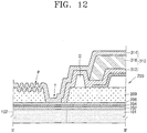
- FIG. 12 is a cross-sectional view taken along line II-II' of FIG. 3 , according to another embodiment.
- a display unit 200 may be formed on the island 101.
- the display unit 200 may include the thin film transistor TFT of FIG. 4 including inorganic layers and the organic light-emitting device 230 of FIG. 4 that is electrically connected to the thin film transistor TFT.
- the passivation layer 209 may be interposed between the thin film transistor TFT and the organic light-emitting device 230.
- the inorganic layers of the thin film transistor TFT may be the first insulating layer 204 and the second insulating layer 206.
- the buffer layer 202, the first insulating layer 204, the second insulating layer 206, and the passivation layer 209 formed on the island 101 may extend over the connection unit 102.
- the passivation layer 209 on the connection unit 102 may include a trench T exposing a portion of the first insulating layer 204 or the second insulating layer 206 under the passivation layer 209.
- At least one of the inorganic layers 312 and 314 of the encapsulation layer 310 may contact the exposed portion of the first insulating layer 204 or the second insulating layer 206 via the trench T.
- a dam unit D surrounding at least a portion of the display region DA of the display unit 200 may be formed in the non-display region of the display unit 200.
- the organic layer 316 may face or contact an inner surface of the dam unit D or may overlap a portion of the dam unit D, but may not extend beyond the dam unit D.
- the inorganic layers 312 and 314 may cover the dam unit D and may contact each other around the dam unit D.
- an outermost inorganic layer of the encapsulation layer 310 may extend over the connection unit 102.
- the second inorganic layer 314 on the outermost side of the encapsulation layer 310 may be formed on both the island 101 and the connection unit 102.
- the passivation layer 209 formed on the connection unit 102 may be covered with the second inorganic layer 314. Since the passivation layer 209 may be formed of an organic material as described above, when the passivation layer 209 formed on the connection unit 102 is covered with the second inorganic layer 314 formed of an inorganic material, exposure of a surface of the passivation layer 209 to oxygen or moisture may be prevented, and thus infiltration of oxygen or moisture into the display unit 200 via the passivation layer 209 may be prevented.
- flexures P may be formed on at least a portion of the region on the connection unit 102.
- the flexures P may be formed by patterning the passivation layer 209.
- the flexures P may be formed using various methods, such as, by forming steps or the like on the connection unit 102. A method of forming the flexures P is not limited thereto.
- the flexures P may be formed at a location corresponding to the connection region C of FIG. 3 where the island 101 and the connection unit 102 are connected to each other.
- the flexures P may reduce stress that may concentrate on a connecting portion between the connection unit 102 and the island 101 during elongation of the substrate 10 of FIG. 1 .
- the flexures P may prevent the second inorganic layer 314 extending over the connection unit 102 from being damaged, for example, cracked.
- FIG. 13 is a cross-sectional view taken along line I-I' of FIG. 3 , according to another embodiment.
- a display unit 200' may be disposed on the island 101, and may include a source electrode 2111, a drain electrode 2112, an active layer 2130, an organic light-emitting device 2125, a gate electrode 2140, a light protection layer 2105, a color filter 2106, and an auxiliary electrode 2150.
- FIG. 13 does not show an encapsulation layer on the display unit 200'.
- the display unit 200' may be encapsulated by an encapsulation layer.
- the island 101 may include the same material as the materials mentioned in the previous embodiments.
- a buffer layer 2102 may be formed on the island 101.
- the source electrode 2111 and the drain electrode 2112 may be formed on the buffer layer 2102.
- a first electrode 2120 of the organic light-emitting device 2125 may also be formed on the buffer layer 2102.
- the first electrode 2120 may extend from the source electrode 2111 or the drain electrode 2112.
- the first electrode 2120 may include the same material used to form the source electrode 2111 or the drain electrode 2112, and may be integrally formed with the source electrode 2111 or the drain electrode 2112. Thus, process efficiency of the display unit 200' may improve.
- the active layer 2130 may be formed on the source electrode 2111 and the drain electrode 2112.
- the active layer 2130 corresponds to a space between the source electrode 2111 and the drain electrode 2112.
- the active layer 2130 may contact the source electrode 2111 and the drain electrode 2112, and, in particular, may contact respective lateral surfaces of the source electrode 2111 and the drain electrode 2112 that face each other.
- the active layer 2130 may contact a lateral surface facing the drain electrode 2112 from among the lateral surfaces of the source electrode 2111 and may contact a lateral surface facing the source electrode 2111 from among the lateral surfaces of the drain electrodes 2112.
- the active layer 2130 may contact a portion of the upper surface of the source electrode 2111 and a portion of the upper surface of the drain electrode 2112. Accordingly, contact areas between the active layer 2130 and the source electrode 2111 and the drain electrode 2112 increase, and thus a short channel structure may be implemented.
- the active layer 2130 may include various materials.
- the active layer 2130 may include an oxide semiconductor material.
- the active layer 2130 may include a ZnO-based oxide.
- the active layer 2130 may include an oxide semiconductor material containing In, Ga, and/or Sn.
- the active layer 2130 may include G-I-Z-O [(In 2 O 3 )a(Ga 2 O 3 )b(ZnO)c], wherein a, b, and c are real numbers that respectively satisfy a ⁇ 0, b ⁇ 0, and c>0.
- the active layer 2130 may include an oxide of a material selected from Group 12, 13, and 14 metal elements (e.g., zinc (Zn), indium (In), gallium (Ga), stannum (Sn), cadmium (Cd), germanium (Ge), and hafnium (Hf)), and a combination thereof.
- metal elements e.g., zinc (Zn), indium (In), gallium (Ga), stannum (Sn), cadmium (Cd), germanium (Ge), and hafnium (Hf)
- the gate electrode 2140 has a region that overlaps at least a portion of the active layer 2130.
- the gate electrode 2140 may include various highly-conductive materials.
- the gate electrode 2140 may include a low resistance metal material, for example, molybdenum (Mo), aluminum (Al), copper (Cu), or titanium (Ti).
- a first insulation layer 2135 is formed between the gate electrode 2140 and the active layer 2130.
- the first insulation layer 2135 electrically insulates the gate electrode 2140 from the active layer 2130.
- the first insulating layer 2135 may not cover at least one region of the first electrode 2120. According to another embodiment, the first insulating layer 2135 may cover at least an edge of the first electrode 2120.
- the gate electrode 2140 is formed on the first insulating layer 2135.
- the first insulating layer 2135 may include various insulating materials.
- the first insulating layer 2135 may include an inorganic material, such as silicon oxide, silicon nitride, or aluminum oxide.
- the first insulating layer 2135 may include an organic material including a polymer.
- a second insulation layer 2144 is formed on the gate electrode 2140.
- the second insulating layer 2144 covers the gate electrode 2140.
- the second insulating layer 2144 is formed on the first insulating layer 2135.
- the second insulating layer 2144 may not cover at least one region of the first electrode 2120.
- the second insulating layer 2144 may cover the first insulating layer 2135, in a region corresponding to an upper surface of the first electrode 2120.
- At least a portion of the first insulating layer 2135 may be exposed without being covered with the second insulating layer 2144, in the region corresponding to the upper surface of the first electrode 2120.
- the second insulating layer 2144 may include various insulating materials.
- the second insulating layer 2144 may include an inorganic material, such as silicon oxide, silicon nitride, or aluminum oxide.
- the second insulating layer 2144 may include an organic material including a polymer.
- the auxiliary electrode 2150 may be formed on the second insulating layer 2144.
- the auxiliary electrode 2150 contacts at least a portion of one of the source electrode 2111 and the drain electrode 2112.
- the first insulating layer 2135 and the second insulating layer 2144 may expose at least one region of at least one of the source electrode 2111 and the drain electrode 2112, and the auxiliary electrode 2150 may contact the exposed region.
- the auxiliary electrode 2150 may not face at least a portion of the entire region of the first electrode 2120 that is not covered with the first insulating layer 2135 and the second insulating layer 2144.
- the auxiliary electrode 2150 improves electrical characteristics of the source electrode 2111 and the drain electrode 2112.
- electrical resistances of the source electrode 2111 and the drain electrode 2112 may increase. This problem may be compensated by forming the auxiliary electrode 2150 of a material having low resistivity to improve electrical properties of the source electrode 2111 and the drain electrode 2112.
- the auxiliary electrode 2150 may include various conductive materials, for example, a highly-conductive metal material. According to another embodiment, the auxiliary electrode 2150 may include Cu, Ag, Al, Mo, or Au. According to one embodiment, the auxiliary electrode 2150 is formed to be spaced apart from the active layer 2130 to prevent a component of the auxiliary electrode 2150 from being diffused into the active layer 2130 and damaging the active layer 2130.
- the auxiliary electrode 2150 may be formed on a different level from the level of the gate electrode 2140 on the second insulating layer 2144, thereby minimizing interference in the gate electrode 2140 and enabling precise patterning of the gate electrode 2140 and the auxiliary electrode 2150.
- the auxiliary electrode 2150 may be formed on the first insulating layer 2135 on the same level as that of the gate electrode 2140.
- a passivation layer 2145 is formed on the second insulating layer 2144.
- the passivation layer 2145 covers the auxiliary electrode 2150.
- the passivation layer 2145 may not cover at least one region of the first electrode 2120.
- the passivation layer 2145 may cover the second insulating layer 2144 in the region corresponding to the upper surface of the first electrode 2120. According to another embodiment, at least a portion of the second insulating layer 2144 may be exposed without being covered with the passivation layer 2145 in the region corresponding to the upper surface of the first electrode 2120.
- the passivation layer 2145 may be a single layer formed of an organic material, or may be a multi-layer structure including a plurality of organic material layers.
- the organic material may include a commercial polymer such as PMMA or PS, a polymer derivative having a phenol-based group, an acryl-based polymer, an imide-based polymer, an acryl ether-based polymer, an amide-based polymer, a fluorine-based polymer, a p-xylene-based polymer, a vinyl alcohol-based polymer, a blend thereof, or the like.
- the passivation layer 2145 may be a stack of an inorganic insulation layer and an organic insulation layer.
- the first insulating layer 2135, the second insulating layer 2144, and the passivation layer 2145 may also be formed on the connection unit 102 of FIG. 3 .
- the first insulating layer 2135 or the second insulating layer 2144 may be exposed via the trench T of FIG. 3 .
- the exposed first insulating layer 2135 or the exposed second insulating layer 2144 may contact the encapsulation layer 300 of FIG. 3 .
- An intermediate layer 2123 is formed on an upper surface of the first electrode 2120.
- the intermediate layer 2123 may include an organic emission layer to generate visible light.
- the intermediate layer 2123 may generate various colors of lights. In other words, the intermediate layer 2123 may generate red (R), green (G), and blue (B) lights, for example. According to another embodiment, the intermediate layer 2123 may generate white (W) light.
- a second electrode 2122 is formed on the intermediate layer 2123.
- the second electrode 2122 may include various conductive materials, for example, Li, Ca, LiF/Ca, LiF/Al, Al, Mg, and Ag.
- the light protection layer 2105 faces the active layer 2130.
- the light protection layer 2105 may face a surface opposite to a surface facing the gate electrode 2140 among the surfaces of the active layer 2130. Accordingly, the active layer 2130 may be prevented from being damaged by light.
- an over-coating layer 2103 may be formed on a substrate to cover the light protection layer 2105.
- the over-coating layer 2103 may be formed below the buffer layer 2102.
- the color filter 2106 faces at least one region of the first electrode 2120.
- the color filter 2106 may face a region of the first electrode 2120 that is overlapped by the intermediate layer 2123.
- the color filter 2106 may be disposed between the first electrode 2120 and the substrate.
- the color filter 2106 may be formed on the substrate, and the over-coating layer 2103 may be formed to cover the color filter 2106.
- the over-coating layer 2103 may be formed below the buffer layer 2102.
- the color filter 2106 may face the first electrode 2120, and thus a display apparatus generating various colors may be realized.
- the light protection layer 2105 may also be formed of a color filter material based on one color, for example, a red (R) color.
- the over-coating layer 2103 may be formed to cover the light protection layer 2105 and the color filter 2106.
- FIG. 14 is a cross-sectional view taken along line I-I' of FIG. 3 , according to yet another embodiment.
- a display unit 200 may be disposed on the island 101, and may include at least one organic light-emitting device 230 and a thin film transistor TFT that is electrically connected to the organic light-emitting device 230.
- the organic light-emitting device 230 may include a first electrode 231, an intermediate layer 233, and a second electrode 232.
- a passivation layer 209 may be disposed between the organic light-emitting device 230 and the thin film transistor TFT.
- FIG. 14 does not show an encapsulation layer on the display unit 200. However, the display unit 200 may be encapsulated by an encapsulation layer.
- a pixel defining layer 219 exposes an area of the first electrode 231 and defines a pixel region of the organic light-emitting device 230.
- a light blocking layer BL may be disposed on a remaining region except for the pixel region defined by the pixel defining layer 219.
- the light blocking layer BL may be formed on an upper surface of the pixel defining layer 219.
- the pixel defining layer 219 or the passivation layer 209 may include a material that is capable of blocking light.
- the light blocking layer BL may be disposed between the island 101 and the thin film transistor TFT.
- FIG. 15 is a magnified plan view of a portion A of FIG. 1 .
- FIG. 16 is a cross-sectional view taken along line VI-VI' of FIG. 15
- FIG. 17 is a cross-sectional view taken along line VII-VII' of FIG. 15 , according to an embodiment.
- the display apparatus 10 may include a plurality of islands 101, a plurality of connection units 102 that are connecting the plurality of islands 101 to one another, and a plurality of display units 200 respectively disposed on the plurality of islands 101.
- Inorganic layers and a passivation layer 209 of the display units 200 may be consecutively formed on the islands 101 and the connection units 102.
- the inorganic layers may be the buffer layer 202, the first insulating layer 204, and the second insulating layer 206 included in the thin film transistor TFT of FIG. 4 , respectively.
- Each of the plurality of display units 200 may be encapsulated by the encapsulation layer 300 of FIG. 4 .
- the encapsulation layer 300 may contact an exposed portion of the first insulating layer 204 or the second insulating layer 206 via the trench T.
- first connection units 102a positioned on opposite sides of one island 101 and each extending in the first direction X
- second connection units 102b positioned on opposite sides of the island 101 and each extending in the second direction Y may be connected to the island 101.
- a first wiring unit may be positioned on the two first connection units 102a, and a second wiring unit may be positioned on the two second connection units 102b.
- the first wiring unit may include a first voltage line V1, a second voltage line V2, and at least one data line DL
- the second wiring unit may include at least one scan line SL.
- the first wiring unit and the second wiring unit may cross each other on the island 101.
- the first wiring unit may extend in the first direction X and may include a region curved along a through hole V in the second direction Y. Since the first wiring unit may extend in the first direction X and may repeat a curved shape at regular intervals, non-uniformity of brightness or the like between the display units 200 due to the first wiring unit may be reduced or prevented. A plurality of first wiring units extending in the same direction may be formed not to overlap each other to thereby minimizing interferences therebetween.
- the second wiring unit may extend in the second direction Y, and a curved shaped in the first direction X may be repeated at regular intervals, non-uniformity of brightness or the like between the display units 200 due to the second wiring unit may be reduced or prevented.
- a plurality of second wiring units extending in the same direction may be formed not to overlap each other to thereby minimizing interferences therebetween.
- the first wiring unit and the second wiring unit may include the same material.
- the first wiring unit and the second wiring unit may have a stacked structure of Ti/Al/Ti and may include the same material used to form the source electrode 207 and the drain electrode 208, which are highly flexible.
- FIG. 16 illustrates an example in which a scan line SL is formed on a second connection unit 102b.
- the buffer layer 202, the first insulating layer 204, the second insulating layer 206, and the passivation layer 209 may be sequentially stacked on the second connection unit 102b in the stated order, and the scan line SL may be formed on the passivation layer 209. Since the scan line SL is connected to the gate electrode 205 of the thin film transistor to apply a scan signal to the thin film transistor, the scan line SL and the gate electrode 205 of the thin film transistor may be electrically connected to each other via a contact hole.
- FIG. 17 illustrates an example in which the first voltage line V1, the data line DL, and the second voltage line V2 are formed on a first connection unit 102a.
- the buffer layer 202, the first insulating layer 204, the second insulating layer 206, and the passivation layer 209 may be sequentially stacked on the first connection unit 102a in the stated order, and the first voltage line V1, the data line DL, and the second voltage line V2 may be formed on the passivation layer 209.
- the data line DL may be connected to the drain electrode 208 of the thin film transistor to apply a data signal to the thin film transistor.
- the first voltage line V1 may electrically connect first electrodes 231 of FIG. 4 respectively included in a plurality of display units 200 and separated from one another to one another.
- the second voltage line V2 may have the same pattern as or a similar pattern to the first voltage line V1, and the second voltage line V2 may be electrically connected to the second electrode 232 via a contact hole.
- FIG. 18 is a schematic cross-sectional view of a display apparatus 20, which is a modification of the display apparatus 10 of FIG. 1 .
- the display apparatus 20 may include a substrate 100 including a plurality of islands 101 and a plurality of connection units 102 that are connecting the plurality of islands 101 to one another, a plurality of display units 200 respectively disposed on the plurality of islands 101, a plurality of encapsulation layers 300 respectively encapsulating the plurality of display units 200, and a first protection film 410 and a second protection film 420 respectively disposed on an upper surface and a lower surface of the substrate 100.
- the substrate 100 may include a plurality of through holes V of FIG. 1 that penetrate through the substrate 100 between the connection units 102.
- the substrate 100, the display unit 200, and the encapsulation layer 300 are the same as those described above in the previous embodiments, repeated descriptions thereof may be omitted herein.
- the first protection film 410 and the second protection film 420 may prevent external foreign materials or the like from permeating the display apparatus 20.
- the first protection film 410 and the second protection film 420 are formed of elongation sheets, and thus may be elongated or changed in shape when the display apparatus 20 is elongated or changed in shape.
- the first protection film 410 and the second protection film 420 may be biaxially oriented polypropylene films, biaxially oriented polyethylene terephthalate films, or the like.
- the first protection film 410 and the second protection film 420 may include, but is not limited to, polydimethylsiloxane (PDMS).
- FIG. 19 is a schematic cross-sectional view of a display apparatus 30, which is another modification of the display apparatus 10 of FIG. 1 .
- the display apparatus 30 may include a substrate 100, a plurality of display units 200 disposed on the substrate100, a plurality of encapsulation layers 300 respectively encapsulating the plurality of display units 200, a first protection film 410 and a second protection film 420 respectively disposed on an upper surface and a lower surface of the substrate 100, and a functional layer 500 on the second protection film 420.
- the substrate 100 may include a plurality of islands 101, a plurality of connection units 102 that are connecting the plurality of islands 101 to one another, and a plurality of through holes V penetrating through the substrate 100 between the plurality of connection units 102.
- the plurality of display units 200 may be respectively disposed on the plurality of islands 101.
- the encapsulation layers 300, respectively encapsulating the plurality of display units 200, may also be disposed on the plurality of islands 101.
- the first protection film 410 and the second protection film 420 may prevent external foreign materials or the like from permeating the display apparatus 30.
- the functional layer 500 may include at least one of a polarization layer and a touch screen layer.
- the functional layer 500 may further include an optic film for external light reflection and a protection layer.
- the functional layer 500 is elongatable, and may be elongated when the display apparatus 30 is elongated.
- FIG. 20 is a magnified plan view of a portion A of FIG. 1 , according to another embodiment.
- the substrate 100 may include a plurality of islands 101 spaced apart from one another, a plurality of connection units 102 that are connecting the plurality of islands 101 to one another, and a plurality of through holes V penetrating through the substrate 100 between the plurality of connection units 102.
- a plurality of display units 200 may be disposed on the plurality of islands 101, respectively.
- Each display unit 200 may include at least a display device to realize visible light.
- the display device may be an organic light-emitting device.
- the plurality of display units 200 may be independently encapsulated by a plurality of encapsulation layers 300.
- the plurality of connection units 102 may connect the plurality of islands 101 to one another.
- four connection units 102 are connected to each of the plurality of islands 101 and extend adjacent to the island 101 in different directions, and thus the four connection units 102 may be respectively connected to other four adjacent islands 101 surrounding the island 101.
- the plurality of islands 101 and the plurality of connection units 102 may be formed of the same material and may be connected to each other. In other words, the plurality of islands 101 and the plurality of connection units 102 may be integrally formed to have one body.
- the inorganic layers and the passivation layer 209 of FIG. 4 of the display units 200 may be consecutively formed on the islands 101 and the connection units 102.
- the inorganic layers may include the buffer layer 202 and the first insulating layer 204 and the second insulating layer 206 included in the thin film transistor TFT of FIG. 4 ,
- the encapsulation layer 300 may contact an exposed portion of the first insulating layer 204 or the second insulating layer 206 via the trench T. Accordingly, the encapsulation layer 300 may reduce or prevent infiltration of external moisture and oxygen into the display units 200 via the passivation layer 209 that may be formed of an organic material.
- Wiring units that are electrically connected to the display units 200 may be disposed on the plurality of islands 101.
- each connection unit 102 has at least one curved portion. Accordingly, the shape of the at least one curved portion changes when the substrate 100 is elongated, and intervals between the plurality of islands 101 may increase. Thus, the shape of the display apparatus 10 of FIG. 1 may change two-dimensionally or three-dimensionally.
- the through holes V penetrate through the substrate 100.
- the through holes V may provide separation areas between the plurality of islands 101, reduce the weight of the substrate 100, and improve the flexibility of the substrate 100.
- the shapes of the through holes V change, and thus stress generated during deformation of the substrate 100 is effectively reduced.
- abnormal deformation of the substrate 100 may be prevented, and durability of the substrate 100 may improve.
- convenience and usability of the display apparatus 10 may improve, and the display apparatus 10 may be suitably applied to bending display apparatuses, flexible display apparatuses, or stretchable display apparatuses.
- an encapsulation layer may be prevented from being damaged, and infiltration of external moisture and oxygen may be effectively prevented, thereby improving the reliability of the display apparatus. It should be understood that the scope of the present invention is not restricted by this effect.
Landscapes
- Engineering & Computer Science (AREA)
- Microelectronics & Electronic Packaging (AREA)
- Physics & Mathematics (AREA)
- Optics & Photonics (AREA)
- Chemical & Material Sciences (AREA)
- Inorganic Chemistry (AREA)
- Geometry (AREA)
- Electroluminescent Light Sources (AREA)
- Devices For Indicating Variable Information By Combining Individual Elements (AREA)
Abstract
Description
- The present invention relates to a display apparatus.
- As display technology develops rapidly, various flat panel display apparatuses having excellent characteristics such as a slim profile, a light weight, and low power consumption have been introduced. With the recent development in display technology, flexible display apparatuses have been researched and developed, and stretchable display apparatuses that are capable of being changed to various shapes are being actively researched and developed.
- Meanwhile, a display apparatus having a slim profile and flexible characteristics may include a thin film encapsulation layer to block infiltration of moisture, oxygen, etc. from outside. A conventional thin film encapsulation layer has a configuration in which inorganic layers and organic layers are alternately stacked. However, since the thin film encapsulation layer is integrally formed with a display apparatus, the thin film encapsulation layer may degrade the flexibility of the display apparatus, and the thin film encapsulation layer may be damaged when the shape of the display apparatus is changed.
- One or more embodiments of the present invention provide a display apparatus.
- Additional aspects will be set forth in part in the description which follows and, in part, will be apparent from the description, or may be learned by practice of the presented embodiments.
- According to one or more embodiments of the invention, a display apparatus includes a substrate; a plurality of display units disposed on the substrate, each including a thin film transistor including at least one inorganic layer, a passivation layer disposed on the thin film transistor, and a display device electrically connected to the thin film transistor; and a plurality of encapsulation layers respectively encapsulating the plurality of display units, wherein the substrate includes a plurality of islands spaced apart from one another, a plurality of connection units that are connecting the plurality of islands to one another, and a plurality of through holes penetrating through the substrate between the plurality of connection units, the plurality of display units are disposed on the plurality of islands, respectively, the at least one inorganic layer and the passivation layer extend on the plurality of connection units, the passivation layer includes a trench that exposes a portion of the at least one inorganic layer, and the encapsulation layer contacts an exposed portion of the at least one inorganic layer via the trench.
- The trench may be disposed on a connection unit of the plurality of connection units.
- The trench may extend across a width of the connection unit and may be aligned with a lateral surface of an island of the plurality of islands.
- The trench may be on an island of the plurality of islands and may completely surround a display unit of the plurality of display units.
- The at least one inorganic layer may include a first insulating layer between an active layer and a gate electrode of the thin film transistor, and a second insulating layer disposed on the gate electrode. The trench may expose a portion of the first insulating layer or the second insulating layer.
- The encapsulation layer may contact a lateral surface of an island of the plurality of islands.
- The encapsulation layer may include at least one of tin fluorophosphates glass, chalcogenide glass, tellurite glass, borate glass, and phosphate glass.
- Each of the plurality of encapsulation layers may include at least one inorganic layer and at least one organic layer. The at least one inorganic layer may contact an exposed portion of the at least one inorganic layer of the thin film transistor via the trench.
- At least one of the at least one inorganic layer and the at least one organic layer may include silicon oxide including carbon and hydrogen.
- Each of the plurality of encapsulation layers may include a first inorganic layer, a second inorganic layer, and an organic layer between the first inorganic layer and the second inorganic layer. At least one of the first inorganic layer and the second inorganic layer may contact a lateral surface of the island and may contact an exposed portion of the at least one inorganic layer of the thin film transistor via the trench.
- A connection unit of the plurality of connection units may include flexures disposed on at least a portion of the connection unit, and the second inorganic layer disposed on an outermost side of the encapsulation layer from among the first inorganic layer and the second inorganic layer may extend over the flexures.
- Each of the plurality of display units may include a display region and a non-display region around the display region, and a dam unit surrounding at least a portion of the display region may be disposed in the non-display region. The first inorganic layer and the second inorganic layer may cover the dam unit and contact each other around the dam unit.
- The thin film transistor may include an active layer, a gate electrode, a source electrode, and a drain electrode. The display device may include a first electrode, a second electrode, and an intermediate layer including an organic emission layer between the first electrode and the second electrode. The first electrode may extend from one of the source electrode and the drain electrode. Each of the plurality of display units may be disposed between the first electrode and the island and may further include a color filter including a portion overlapped by the first electrode.
- The plurality of islands and the plurality of connection units may be one body.
- The plurality of islands may be repeated in a first direction and a second direction that is different from the first direction. Four connection units may be connected to each of the plurality of islands. Four connection units connected to one island from among the plurality of islands may extend in different directions and may be respectively connected to four adjacent islands that surround the one island.
- The four connection units may include a pair of first connection units on opposite sides of the one island and each extending in the first direction, and a pair of second connection units on opposite sides of the one island and each extending in the second direction. A first wiring unit may be disposed on the two first connection units, and a second wiring unit may be disposed on the two second connection units. The first wiring unit and the second wiring unit may cross on the one island.
- The first wiring unit may include a region curved in the second direction along a through hole of the plurality of through holes, and the second wiring unit may include a region curved in the first direction along the through hole.
- The thin film transistor may include an active layer, a gate electrode, a source electrode, and a drain electrode. The source electrode, the drain electrode, the first wiring unit, and the second wiring unit may include a same material.
- The first wiring unit may include a first voltage line, a second voltage line, and at least one data line, and the second wiring unit may include at least one scan line.
- The display device may include a first electrode, a second electrode, and an intermediate layer between the first electrode and the second electrode and including an organic emission layer. The first voltage line may electrically connect first electrodes respectively included in the plurality of display units and separated from one another to one another. The second voltage line may electrically connect second electrodes respectively included in the plurality of display units and separated from one another to one another.
- Two adjacent islands among the plurality of islands may be connected to each other by one connection unit. Each of the two adjacent islands connected to the one connection unit and a direction in which the one connection unit extends may make an acute angle.
- Each of the plurality of islands may have a quadrilateral shape, and four corners of each of the plurality of islands may be directed in the first direction and the second direction.
- The display apparatus may further include a first protection film and a second protection film respectively disposed on an upper surface and a lower surface of the substrate. The first protection film and the second protection film may include elongation sheets.
- At least some of the above features and other features according to the invention are set out in the claims.
- These and/or other aspects of the invention will become apparent and more readily appreciated from the following description of embodiments thereof, taken in conjunction with the accompanying drawings in which:
-
FIG. 1 is a schematic plan view of a display apparatus, according to an embodiment of the present invention; -
FIG. 2 is a magnified plan view of a portion A ofFIG. 1 , according to an embodiment of the invention; -
FIG. 3 is a schematic plan view of a unit ofFIG. 1 , according to an embodiment of the invention; -
FIG. 4 is a cross-sectional view taken along lineI-I' ofFIG. 3 , according to an embodiment of the invention; -
FIG. 5 is a cross-sectional view taken along line II-II' ofFIG. 3 , according to an embodiment of the invention; -
FIG. 6 is a cross-sectional view taken along line III-III' ofFIG. 3 , according to an embodiment of the invention; -
FIG. 7 is a cross-sectional view taken along line II-II' ofFIG. 3 , according to another embodiment of the invention; -
FIG. 8 is a schematic plan view of a unit ofFIG. 1 , according to another embodiment of the invention; -
FIG. 9 is a cross-sectional view taken along line I-I' ofFIG. 3 , according to another embodiment of the invention; -
FIG. 10 is a cross-sectional view taken along line II-II' ofFIG. 3 , according to another embodiment of the invention; -
FIG. 11 is a cross-sectional view taken along line III-III' ofFIG. 3 , according to another embodiment of the invention; -
FIG. 12 is a cross-sectional view taken along line II-II' ofFIG. 3 , according to another embodiment of the invention; -
FIG. 13 is a cross-sectional view taken along line I-I' ofFIG. 3 , according to another embodiment of the invention; -
FIG. 14 is a cross-sectional view taken along line I-I' ofFIG. 3 , according to yet another embodiment of the invention; -
FIG. 15 is a magnified plan view of a portion A ofFIG. 1 ; -
FIG. 16 is a cross-sectional view taken along line VI-VI' ofFIG. 15 , according to an embodiment of the invention; -
FIG. 17 is a cross-sectional view taken along line VII-VII' ofFIG. 15 , according to an embodiment of the invention; -
FIG. 18 is a schematic cross-sectional view of a display apparatus, which is a modification of the display apparatus ofFIG. 1 ; -
FIG. 19 is a schematic cross-sectional view of a display apparatus, which is another modification of the display apparatus ofFIG. 1 ; and -
FIG. 20 is a magnified plan view of a portion A ofFIG. 1 , according to another embodiment of the invention. - The present invention allows for various changes and numerous embodiments, and particular embodiments will be illustrated in the drawings and described in detail in the written description. However, this is not intended to limit the scope of the present invention to particular modes of practice, and it is to be appreciated that all changes, equivalents, and substitutes that do not depart from the technical scope of the present invention are encompassed in the present invention. In the following description of the present invention, a detailed description of disclosed embodiments is provided to clarify exemplary features of the present invention.
- While such terms as "first", "second", etc., may be used to describe various components, such components must not be limited to the above terms. The above terms may be used to distinguish one component from another.
- The terms used in the present specification are merely used to describe particular embodiments, and are not intended to limit the scope of the present invention. An expression used in a singular encompasses the expression in a plural, unless it has a clearly different meaning in the context. In the drawings, components may be exaggerated, omitted, or schematically illustrated for convenience and clarity of explanation. In other words, sizes and thicknesses of components in the drawings may not reflect actual sizes and thicknesses thereof.
- One or more embodiments of the present invention will be described below in more detail with reference to the accompanying drawings. Those components that are the same or are in correspondence are rendered the same reference numeral regardless of the figure number, and redundant explanations may be omitted.
-
FIG. 1 is a schematic plan view of adisplay apparatus 10, according to an embodiment of the present invention, andFIG. 2 is a magnified plan view of a portion A ofFIG. 1 , according to an embodiment of the invention. - Referring to
FIG. 1 , thedisplay apparatus 10 may include asubstrate 100 anddisplay units 200 on thesubstrate 100. - The
substrate 100 may include various materials. Thesubstrate 100 may include a material, such as glass, metal, or an organic material. - According to another embodiment, the
substrate 100 may include a flexible material. For example, thesubstrate 100 may include a material that can be easily bent, folded, or rolled. Theflexible substrate 100 may include a flexible material such as ultrathin glass, metal, or plastic. When thesubstrate 100 includes plastic, thesubstrate 100 may include polyimide (PI). As another example, thesubstrate 100 may include another type of plastic material. - The
substrate 100 may include a plurality ofislands 101 spaced apart from one another, a plurality ofconnection units 102 that are connecting the plurality ofislands 101 to one another, and a plurality of through holes V penetrating through thesubstrate 100 between the plurality ofconnection units 102. As will be described with reference toFIG. 18 , afirst protection film 410 and asecond protection film 420 may be respectively disposed on an upper surface and a lower surface of thesubstrate 100. - The plurality of
islands 101 may be arranged to be spaced apart from one another. For example, the plurality ofislands 101 may be repeated in a first direction X and a second direction Y that is different from the first direction X to form a planar lattice pattern. For example, the first direction X and the second direction Y may intersect at 90° angle. As another example, the first direction X and the second direction Y may meet at either an acute or an obtuse angle. - A plurality of
display units 200 may be disposed on the plurality ofislands 101, respectively. Eachdisplay unit 200 may include at least a display device to realize visible light. Eachdisplay unit 200 will be described below in detail with reference toFIG. 4 . - The plurality of
connection units 102 may connect the plurality ofislands 101 to one another. For example, fourconnection units 102 of each of theisland 101 are extended to be connected to each of theadjacent islands 101 in different directions such that the fourconnection units 102 may be respectively connected to the fouradjacent islands 101 surrounding theisland 101. The plurality ofislands 101 and the plurality ofconnection units 102 may be formed of the same material and may be connected to each other. In other words, the plurality ofislands 101 and the plurality ofconnection units 102 may be integrally formed with each other. - The through holes V penetrate through the
substrate 100. The through holes V may provide separation areas between the plurality ofislands 101, reducing the weight of thesubstrate 100 while improving the flexibility of thesubstrate 100. When thesubstrate 100 is bent, rolled, or the like, the shapes of the through holes V change to effectively reduce the stress generated during deformation of thesubstrate 100. Thus, abnormal deformation and stress concentration of thesubstrate 100 under deformation may be prevented, and durability of thesubstrate 100 may improve. - The through holes V may be formed by removing selective regions of the
substrate 100 via etching or the like. As another example, thesubstrate 100 may be manufactured to include the through holes V during the manufacture of thesubstrate 100. As another example, after the plurality ofdisplay units 200 are formed on thesubstrate 100, the through holes V may be formed by patterning thesubstrate 100. The through holes V may be formed in thesubstrate 100 in various ways, and a method of forming the through holes V may not be limited to the examples described herein. - Hereinafter, a unit U refers to the basic unit of the
substrate 100, and a structure of thesubstrate 100 will be described in more detail with reference to the unit U. - The unit U may be repeated in the first direction X and the second direction Y. In other words, the
substrate 100 may be understood as a combination of a plurality of units U repeated in the first direction X and the second direction Y. Each unit U may include anisland 101 and at least oneconnection unit 102 connected to theisland 101. For example, fourconnection units 102 may be connected to oneisland 101. - The
islands 101 of two adjacent units U may be spaced apart from each other, andconnection units 102 of the two adjacent units U may be connected to each other. Aconnection unit 102 included in a unit U may be referred to as a partial region of theconnection unit 102 that is within the unit U or may be referred to as the whole of aconnection unit 102 between twoadjacent islands 101 that connects the twoadjacent islands 101 to each other. - Four adjacent units U among the plurality of units U form closed curves CL between the four units U, and the closed curves CL may define an empty space herein referred to as a through hole V. The through hole V may also be referred to as a separation area V. The separation area is formed by removing one region of the
substrate 100, and may improve the flexibility of thesubstrate 100 while reducing stress that is generated when thesubstrate 100 is deformed. Eachconnection unit 102 may have a smaller width than a width of eachisland 101, and the separation area may contact theislands 101 of the four units U. - Two adjacent units U among the plurality of units U may be symmetrical to each other. In detail, as shown in
FIG. 1 , one unit U may be symmetrical to another unit U adjacent to the one unit U in the second direction Y, about an axis of symmetry that is parallel to the first direction X. At the same time, one unit U may be symmetrical to another unit U adjacent to the one unit U in the first direction X, about an axis of symmetry that is parallel to the second direction Y. - An angle θ between a direction in which a
connection unit 102 extends and a lateral surface of anisland 101 to which theconnection unit 102 is connected may be an acute angle. For example, when eachisland 101 is a quadrilateral and is disposed such that each of the four corners thereof is directed in the first direction X or the second direction Y, theconnection units 102 may be connected to theisland 101 at regions adjacent to the four corners and may extend in a direction parallel to the second direction Y or the first direction X. In other words, theconnection units 102 connected to the corners directed to the first direction X may be directed in the second direction Y or a direction -Y that is opposite to the second direction Y, and theconnection units 102 connected to the corners directed in the second direction Y may be directed in the first direction X or a direction -X that is opposite to the first direction X. - Thus, each of the lateral surfaces of two
adjacent islands 101 connected to oneconnection unit 102 may respectively make acute angles with the direction in which theconnection unit 102 extends. Accordingly, theislands 101 may be densely arranged, and the areas of the separation areas may be maximized by minimizing the lengths of theconnection units 102. As shown inFIG. 2 , thesubstrate 100 may exhibit an elongation property. -
FIG. 2 illustrates a shape of thesubstrate 100 before and after thesubstrate 100 is elongated both in the first direction X and the second direction Y. Referring toFIG. 2 , when thesubstrate 100 is elongated, the angles formed by theconnection units 102 and the lateral surfaces of theislands 101 to which theconnection units 102 are connected increase (θ<θ'), and thus the separation areas may enlarge. Accordingly, intervals between theislands 101 may increase, and thus thesubstrate 100 may be elongated both in the first direction X and the second direction Y. - Since each
connection unit 102 has a smaller width than a width of eachisland 101, a shape change corresponding to the increase of the angle θ while an external force is applied to thesubstrate 100 may mainly occur in theconnection units 102, and the shapes of theislands 101 may not substantially change during elongation of thesubstrate 100. Thus, thedisplay units 200 on theislands 101 may be stably maintained even when thesubstrate 100 is elongated, and accordingly thedisplay apparatus 10 may be suited for display apparatuses that require flexibility, for example, bending display apparatuses, flexible display apparatuses, or stretchable display apparatuses. - Moreover, since stress concentrates on connecting portions of the
connection units 102 that are connected to the lateral surfaces of theislands 101 during elongation of thesubstrate 100, connecting regions C of theconnection units 102 may include curved surfaces to prevent tearing or the like of theconnection units 102 due to the concentration of the stress. -
FIG. 3 is a schematic plan view of a unit U ofFIG. 1 ,FIG. 4 is a cross-sectional view taken along line I-I' ofFIG. 3 ,FIG. 5 is a cross-sectional view taken along line II-II' ofFIG. 3 , andFIG. 6 is a cross-sectional view taken along line III-III' ofFIG. 3 , according to an embodiment.FIG. 7 is a cross-sectional view taken along line II-II' ofFIG. 3 , according to another embodiment.FIG. 8 is a schematic plan view of another example of a unit U ofFIG. 1 . - Referring to
FIGS. 3-8 , adisplay unit 200 and anencapsulation layer 300 encapsulating thedisplay unit 200 may be on anisland 101 of a unit U. - The
display unit 200 may be located on theisland 101 and may include a display region DA and a non-display region NDA around the display region DA. In the display region DA, at least one organic light-emittingdevice 230 emitting, for example, red (R), blue (B), green (G), or white (W) light, may be located. Herein, the organic light-emittingdevice 230 may be referred to and described as the display device. However, embodiments of the present invention are not limited thereto, and thedisplay unit 200 may include various other types of display devices, such as a liquid crystal display. - The
display unit 200 may include one organic light-emittingdevice 230 emitting red (R), blue (B), green (G), or white (W) light, and thus onedisplay unit 200 may form one sub-pixel. As another example, thedisplay unit 200 may include a plurality of organic light-emittingdevices 230 that emit different lights. For example, onedisplay unit 200 may form a pixel by including an organic light-emittingdevice 230 emitting red (R) light, an organic light-emittingdevice 230 emitting green (G) light, and an organic light-emittingdevice 230 emitting blue (B) light. As another example, thedisplay unit 200 may include a plurality of pixels. - Organic light-emitting
devices 230 within thedisplay unit 200 may be arranged in various configurations, such as an RGB configuration, a pentile structure, and a honeycomb structure, depending on the efficiency of a material included in an organic emission layer. - Referring to
FIG. 4 , abuffer layer 202 may be formed on theisland 101. For example, thebuffer layer 202 may be formed of an inorganic material (e.g., silicon oxide, silicon nitride, silicon oxynitride, aluminum oxide, aluminum nitride, titanium oxide, and titanium nitride), an organic material (e.g., polyimide, polyester, and acryl), or stacks of inorganic and organic materials. Thebuffer layer 102 may be formed on both theisland 101 and theconnection unit 102. - A thin film transistor TFT may include an
active layer 203, agate electrode 205, asource electrode 207, and adrain electrode 208. A case of a top gate type thin film transistor TFT in which theactive layer 203, thegate electrode 205, thesource electrode 207, and thedrain electrode 208 are sequentially formed in the stated order will now be described. However, the present embodiment is not limited thereto, and various types of thin film transistors TFT, such as a bottom gate type thin film transistor TFT, may be employed. - The
active layer 203 may include a semiconductor material, for example, amorphous silicon or polycrystalline silicon. However, the present embodiment is not limited thereto, and theactive layer 203 may include various materials. According to another embodiment, theactive layer 203 may include an organic semiconductor material or the like. According to another embodiment, theactive layer 203 may include an oxide semiconductor material. For example, theactive layer 203 may include an oxide of a material selected from Group 12, 13, and 14 metal elements (e.g., zinc (Zn), indium (In), gallium (Ga), stannum (Sn), cadmium (Cd), and germanium (Ge)) and a combination thereof. - A first insulating
layer 204 may be formed on theactive layer 203. The first insulatinglayer 204 may be formed of an inorganic material, such as silicon oxide and/or silicon nitride, in a multi-layer structure or a single-layer structure. The first insulatinglayer 204 insulates theactive layer 203 from thegate electrode 205. The first insulatinglayer 204 may be formed on both theisland 101 and theconnection unit 102. - The
gate electrode 205 may be formed on the first insulatinglayer 204 to overlap theactive layer 203. Thegate electrode 205 may be connected to a gate line (not shown) that applies an ON/OFF signal to the thin film transistor TFT. Thegate electrode 205 may include a low resistance metal material. Thegate electrode 205 may be formed of at least one of aluminum (Al), platinum (Pt), palladium (Pd), silver (Ag), magnesium (Mg), gold (Au), nickel (Ni), neodymium (Nd), iridium (Ir), chromium (Cr), calcium (Ca), molybdenum (Mo), titanium (Ti), tungsten (W), and copper (Cu) in a single-layered or a multi-layered structure. - A second insulating
layer 206 may be formed on the gate electrode 205and the first insulatinglayer 204. The secondinsulating layer 206 insulates thesource electrode 207 and thedrain electrode 208 from thegate electrode 205. The secondinsulating layer 206 may be formed of an inorganic material in a multi-layer structure or a single-layer structure. For example, the inorganic material may be metal oxide or metal nitride. In detail, the inorganic material may include silicon oxide (SiO2), silicon nitride (SiNx), silicon oxynitride (SiON), aluminum oxide (Al2O3), titanium oxide (TiO2), tantalum oxide (Ta2O5) hafnium oxide (HfO2), zirconium oxide (ZrO2), or the like. - According to another embodiment, the second insulating
layer 206 may be a single layer formed of an organic material, or may be a multi-layer structure including a plurality of organic material layers. The organic material may include a commercial polymer such as polymethyl methacrylate (PMMA) or polystyrene (PS), a polymer derivative having a phenol-based group, an acryl-based polymer, an imide-based polymer, an acryl ether-based polymer, an amide-based polymer, a fluorine-based polymer, a p-xylene-based polymer, a vinyl alcohol-based polymer, a blend thereof, or the like. Apassivation layer 209 may be a stack of an inorganic insulation layer and an organic insulation layer. - The second
insulating layer 206 may be formed on both theisland 101 and theconnection unit 102. - The
source electrode 207 and thedrain electrode 208 are formed on the second insulatinglayer 206. Thesource electrode 207 and thedrain electrode 208 may be formed of at least one selected from a group including aluminum (Al), platinum (Pt), palladium (Pd), silver (Ag), magnesium (Mg), gold (Au), nickel (Ni), neodymium (Nd), iridium (Ir), chromium (Cr), calcium (Ca), molybdenum (Mo), titanium (Ti), tungsten (W), and copper (Cu) in a single-layered or a multi-layered structure. Thesource electrode 207 and thedrain electrode 208 contact theactive layer 203 via contact holes formed in the second insulatinglayer 206 and the first insulatinglayer 204. - The
passivation layer 209 may cover the thin film transistor TFT. Thepassivation layer 209 may planarize steps caused by the thin film transistor TFT, thereby preventing the organic light-emittingdevice 230 from being damaged by unevenness. - The
passivation layer 209 may be a single layer formed of an organic material, or may be a multi-layer structure including a plurality of organic material layers. The organic material may include a commercial polymer such as PMMA or PS, a polymer derivative having a phenol-based group, an acryl-based polymer, an imide-based polymer, an acryl ether-based polymer, an amide-based polymer, a fluorine-based polymer, a p-xylene-based polymer, a vinyl alcohol-based polymer, a blend thereof, or the like. Thepassivation layer 209 may be a stack of an inorganic insulation layer and an organic insulation layer. - The
passivation layer 209 may be formed on both theisland 101 and theconnection unit 102. Thepassivation layer 209 on theconnection unit 102 may include a trench T exposing an inorganic layer under thepassivation layer 209. The inorganic layer that is exposed under thepassivation layer 209 may be thebuffer layer 202, the first insulatinglayer 204, and/or the second insulatinglayer 206. - The trench T may extend across the width of the
connection unit 102. Accordingly, the trench T may reduce or prevent infiltration of external moisture into thedisplay unit 200 via thepassivation layer 209 formed of an organic material. - For example, as shown in
FIG. 3 , the trench T may extend across the width of theconnection unit 102, in a connecting region C where theisland 101 and theconnection unit 102 are connected to each other, and may be aligned with a lateral surface of theisland 101. In detail, an extension of the lateral surface of theisland 101 may be within the width of the trench T. - As another example, as shown in
FIG. 8 , a trench T' may be disposed on theisland 101 to completely surround thedisplay unit 200. Accordingly,separate passivation layers 209 may be formed on each of theislands 101, respectively. - The organic light-emitting
device 230 is formed on thepassivation layer 209. The organic light-emittingdevice 230 may include afirst electrode 231, asecond electrode 232 opposite to thefirst electrode 231, and anintermediate layer 233 between thefirst electrode 231 and thesecond electrode 232. - The
first electrode 231 may be electrically connected to either thesource electrode 207 or thedrain electrode 208. Thefirst electrode 231 may have various shapes. For example, thefirst electrode 231 may be patterned to have an island shape. - The
first electrode 231 may be formed on thepassivation layer 209 and may be electrically connected to the thin film transistor TFT via a contact hole formed in thepassivation layer 209. For example, thefirst electrode 231 may be a reflection electrode including a reflection layer formed of silver (Ag), magnesium (Mg), aluminum (Al), platinum (Pt), palladium (Pd), gold (Au), nickel (Ni), neodymium (Nd), iridium (Ir), chromium (Cr), or a compound thereof. In another example, thefirst electrode 231 may include a transparent electrode layer on the reflection layer. The transparent electrode layer may include at least one selected from a group including indium tin oxide (ITO), indium zinc oxide (IZO), zinc oxide (ZnO), indium oxide (In2O3), indium gallium oxide (IGO), and aluminum zinc oxide (AZO). - The
second electrode 232 may be electrically connected to a second voltage line V2 and may receive a second voltage ELVSS that is lower than a first voltage ELVDD that is applied to thefirst electrode 231. Although the second voltage line V2 and thesecond electrode 232 are shown to be connected to each other via aconnection line 216 shown inFIG. 6 , embodiments of the present invention are not limited thereto. For example, the second voltage line V2 and thesecond electrode 232 may directly contact each other. - The
second electrode 232 may have various shapes. For example, thesecond electrode 232 may be patterned to have an island shape. Thus, a portion of thesecond electrode 232 may be prevented from being exposed even when thesecond electrode 232 is completely covered with theencapsulation layer 300, andencapsulation layers 300 are respectively formed on theislands 101. - The
second electrode 232 may be a transparent electrode. Thesecond electrode 232 may include a metal thin film including Li, Ca, LiF/Ca, LiF/Al, Al, Ag, Mg, or a combination thereof. An auxiliary electrode layer or a bus electrode may be further formed on the metal thin film. The auxiliary electrode layer or the bus electrode may include a material such as ITO, IZO, ZnO, or In2O3. Accordingly, thesecond electrode 232 may transmit light emitted by an organic emission layer included in theintermediate layer 233. In other words, the light emitted by the organic emission layer may travel directly toward thesecond electrode 232, or may be reflected by thefirst electrode 231 that is formed as the reflection electrode and then travel toward thesecond electrode 232. - In the example described above with reference to
FIGS. 3-8 , thedisplay unit 200 is of a top-emission type. However, thedisplay unit 200 according to another embodiment is not limited to the top-emission type. According to another embodiment, thedisplay unit 200 may be a bottom-emission type in which the light emitted by the organic emission layer is emitted toward theisland 101. In this case, thefirst electrode 231 may be a transparent electrode, and thesecond electrode 232 may be a reflection electrode. Thedisplay unit 200 according to yet another embodiment may be of a dual emission type that emits light in both directions toward the top surface and the bottom surface of thedisplay unit 200. - A
pixel defining layer 219 including an insulating material is formed on thefirst electrode 231. Thepixel defining layer 219 may be formed of at least one organic insulating material selected from the group including polyimide, polyamide (PA), acryl resin, benzocyclobutene (BCB) and a phenolic resin, by using a method such as spin coating. Thepixel defining layer 219 exposes an area of thefirst electrode 231. Theintermediate layer 233 including an organic emission layer is formed on the exposed area of thefirst electrode 231. In other words, thepixel defining layer 219 defines a pixel region of an organic light-emitting device. - The
intermediate layer 233 may further include one or more functional layers, such as a hole transport layer (HTL), a hole injection layer (HIL), an electron transport layer (ETL), and an electron injection layer (EIL), in addition to the organic emission layer. - The
encapsulation layer 300 encapsulating thedisplay unit 200 may be formed on thesecond electrode 232. Theencapsulation layer 300 may block external oxygen and moisture and may include a single layer or a plurality of layers. - The
encapsulation layer 300 may include at least one of an organic layer and an inorganic layer. - The organic layer may include PMMA, polycarbonate (PC), PS, acryl-based resin, epoxy-based resin, polyimide, and/or polyethylene. The inorganic layer may include at least one selected from a group including silicon nitride, aluminum nitride, zirconium nitride, titanium nitride, hafnium nitride, tantalum nitride, silicon oxide, aluminum oxide, titanium oxide, tin oxide, cerium oxide, and silicon oxynitride (SiON).
- According to another embodiment, the
encapsulation layer 300 may include a Low temperature Viscosity Transition (LVT) inorganic material. A viscosity transition temperature denotes a minimum temperature at which fluidity can be provided to an LVT inorganic material. The viscosity transition temperature may be less than a denaturalization temperature of a material included in the organic light-emittingdevice 230. - The LVT inorganic material may be, for example, a low liquidus temperature (LLT) material having a glass transition temperature of 200°c or less. In more detail, an LLT material may include at least one of tin fluorophosphates glass, chalcogenide glass, tellurite glass, borate glass, and phosphate glass.
- For example, the tin fluorophosphates glass may include, but is not limited to, Sn of 20-80% by weight, phosphorus (P) of 2-20% by weight, oxygen (O) of 3-20% by weight, and fluorine (F) of 10-36% by weight. The aforementioned glass materials may further include tungsten (W). When tungsten (W) is added to a glass material, a more stable and uniform glass can be produced, and thus the
encapsulation layer 300 may have improved chemical durability. - The LVT inorganic material may include Sn oxide (e.g., SnO or SnO2). For example, when the LVT inorganic material includes SnO, SnO content may be 20% to 100% by weight.
- The LVT inorganic material including Sn oxide may further include, but is not limited to, at least one of P oxide (e.g., P2O5), boron (B) phosphate (BPO4), Sn fluoride (e.g., SnF2), niobium oxide (e.g., NbO), and W oxide (e.g., WO3).
- For example, the LVT inorganic material may include, but is not limited to, SnO; SnO and P2O5; SnO and BPO4; SnO, SnF2 and P2O5; SnO, SnF2, P2O5 and NbO; or SnO, SnF2, P2O5 and WO3.
- The LVT inorganic material may have, but is not limited to, any of the following compositions:
- 1 SnO (100wt%);
- 2 SnO (80wt%) and P2O5 (20wt%);
- 3 SnO (90wt%) and BPO4 (10wt%);
- 4 SnO (20-50wt%), SnF2 (30-60wt%) and P2O5 (10-30wt%) (where a sum of the weights of SnO, SnF2, and P2O5 is 100wt%);
- 5 SnO (20-50wt%), SnF2 (30-60wt%), P2O5 (10-30wt%) and NbO (1-5wt%) (where a sum of the weights of SnO, SnF2, P2O5 and NbO is 100wt%); or
- 6 SnO (20-50wt%), SnF2 (30-60wt%), P2O5 (10-30wt%) and WO3 (1-5wt%) (where a sum of the weights of SnO, SnF2, P2O5 and WO3 is 100wt%).
- Since such an
encapsulation layer 300 is formed of a glass material, even when theencapsulation layer 300 does not include a plurality of layers, theencapsulation layer 300 may effectively prevent infiltration of external moisture and oxygen. - The
encapsulation layer 300 may be formed on oneisland 101 to encapsulate onedisplay unit 200. In other words, when thedisplay apparatus 10 ofFIG. 1 includesN display units 200, N encapsulation layers 300 may be formed. Thus, theencapsulation layer 300 is prevented from being damaged, for example, cracked, when thedisplay apparatus 10 is elongated or when thedisplay apparatus 10 is deformed due to bending, rolling, or the like, thereby improving the reliability and flexibility of thedisplay apparatus 10. - The
encapsulation layer 300 may contact an exposed portion of an inorganic layer of thedisplay unit 200 in the non-display region of thedisplay unit 200. In this case, the inorganic layer of thedisplay unit 200 may be at least one of thebuffer layer 202, the first insulatinglayer 204, and the second insulatinglayer 206. Theencapsulation layer 300 may further extend beyond theisland 101 and may contact the lateral surface of theisland 101. Thus, theencapsulation layer 300 may effectively prevent infiltration of external moisture and/or oxygen. - The
encapsulation layer 300 may contact the exposed portion of the inorganic layer including at least one of thebuffer layer 202, the first insulatinglayer 204, and the second insulatinglayer 206 via the trench T. - For example, as shown in
FIG. 5 , when the second insulatinglayer 206 is formed of an inorganic material, theencapsulation layer 300 may contact an exposed portion of the second insulatinglayer 206 via the trench T. As another example, as shown inFIG. 7 , when the second insulatinglayer 206 is formed of an organic material and the first insulatinglayer 204 below the second insulatinglayer 206 is formed of an inorganic material, a trench T may be formed to expose a portion of the first insulatinglayer 204, and theencapsulation layer 300 may contact the exposed portion of the first insulatinglayer 204 via the trench T. - The trench T may be aligned with the lateral surface of the
island 101. Thedisplay unit 200 is entirely surrounded and encapsulated by theencapsulation layer 300 and the inorganic layer, so that thedisplay unit 200 is isolated, therefore infiltration of external moisture and/or oxygen into thedisplay unit 200 may be effectively reduced or prevented. - As another example, as shown in
FIG. 8 , when the trench T' is formed on theisland 101 and completely surrounds thedisplay unit 200, theencapsulation layer 300 may contact an exposed portion of the first insulatinglayer 204 or the second insulatinglayer 206 via the trench T' and thus may effectively reduce or prevent infiltration of external moisture and/or oxygen. -
FIG. 9 is a cross-sectional view taken along line I-I' ofFIG. 3 FIG. 10 is a cross-sectional view taken along line II-II' ofFIG. 3 , andFIG. 11 is a cross-sectional view taken along line III-III' ofFIG. 3 , according to another embodiment. - Referring to
FIGS. 3 and 9-11 , adisplay unit 200 and anencapsulation layer 310 are formed on anisland 101. Thedisplay unit 200 may include at least one organic light-emittingdevice 230 and a thin film transistor TFT that is electrically connected to the organic light-emittingdevice 230. Since theisland 101 and thedisplay unit 200 are the same as those described above with reference toFIGS. 1-8 , repeated descriptions thereof may be omitted, and only differences therebetween will now be focused. - One
encapsulation layer 310 may be formed on oneisland 101 to encapsulate onedisplay unit 200. - The
encapsulation layer 310 may include, for example, at least one inorganic layer (i.e.,inorganic layers 312 and 314) and at least one organic layer (i.e., an organic layer 316) that are alternately stacked one on another. Although theencapsulation layer 310 includes the twoinorganic layers organic layer 316 inFIGS. 9-11 , embodiments of the present invention are not limited thereto. For example, theencapsulation layer 310 may further include a plurality of additional inorganic layers and a plurality of additional organic layers that are alternately stacked one on another, and the number of stacked inorganic layers and the number of stacked organic layers are not limited. As described above with reference toFIG. 4 , theencapsulation layer 310 may be formed of an LVT inorganic material or may include a layer formed of an LVT inorganic material. - According to an embodiment, the
inorganic layers - The
organic layer 316 may planarize steps caused by thepixel defining layer 219 and may reduce stress generated on theinorganic layers organic layer 316 may include at least one selected from a group including PMMA, PC, PS, acryl-based resin, epoxy-based resin, polyimide, and polyethylene. - According to anther embodiment, the
organic layer 316 may include silicon oxide including carbon and oxygen (hereinafter, referred to as SiOCH). For example, theorganic layer 316 may be formed of a material having a composition formula of SiOxCyHz. - When the
organic layer 316 is formed of SiOCH, theorganic layer 316 may be formed by forming a precursor film on the firstinorganic layer 312 via plasma enhanced chemical vapor deposition (PECVD) by using a raw material gas (e.g., hexamethyldisiloxane) and a reaction gas (e.g., oxygen) and then plasma-curing the precursor film. Theorganic layer 316 and theinorganic layers encapsulation layer 310. - According to another embodiment, at least one of the
inorganic layers inorganic layers - When the
organic layer 316 and at least one of theinorganic layers inorganic layers organic layer 316. In detail, since a film formed of SiOCH has a similar property to an inorganic layer as an oxygen content ratio increases and a carbon content ratio decreases, oxygen content of SiOCH used to form at least one of theinorganic layers organic layer 316, and carbon content of SiOCH used to form at least one of theinorganic layers organic layer 316. - The oxygen and carbon contents of SiOCH may be adjusted during production of an SiOCH film. For example, the SiOCH film may be formed via PECVD by using a raw material gas (e.g., hexamethyldisiloxane) and a reaction gas (e.g., oxygen). In this case, when a flow ratio of oxygen as a reaction gas is increased, the oxygen content of the SiOCH film may be increased and the carbon content thereof may be decreased.
- As such, when the
organic layer 316 and at least one of theinorganic layers inorganic layers organic layer 316 may be consecutively formed within the same chamber by simply adjusting the flow rate of the reaction gas, leading to an improvement in the manufacturing efficiency of theencapsulation layer 310. - According to one embodiment, the
inorganic layers organic layer 316. Theinorganic layers organic layer 316. At least one of theinorganic layers display unit 200 in the non-display region of thedisplay unit 200. In this case, the inorganic layer may be thebuffer layer 202, the first insulatinglayer 204, or the second insulatinglayer 206. At least one of theinorganic layers island 101 and may contact a lateral surface of theisland 101. Accordingly, bonding strength of theencapsulation layer 310 may improve, and theencapsulation layer 310 may effectively prevent infiltration of external moisture and/or oxygen into thedisplay unit 200. - The
buffer layer 202, the first insulatinglayer 204, the second insulatinglayer 206, and thepassivation layer 209 of thedisplay unit 200 may be formed on theconnection unit 102, and thepassivation layer 209 on theconnection unit 102 may include a trench T exposing a portion of the first insulatinglayer 204 or the second insulatinglayer 206 under thepassivation layer 209. In this case, at least one of theinorganic layers layer 204 or the second insulatinglayer 206 via the trench T. - According to another embodiment, a dam unit D surrounding at least a portion of the display region DA of the
display unit 200 may be formed in the non-display region of thedisplay unit 200. - For example, the dam unit D may include a first layer formed of the material used to form the
passivation layer 209, and a second layer formed of the material used to form thepixel defining layer 219. However, embodiments of the present invention are not limited thereto, and the dam unit D may include a single layer. According to some embodiments, a plurality of dam units D may be included. When a plurality of dam units D are included, each of the dam units D has a height increasing in a direction toward the edge of theisland 101. - The dam unit D may include the same material used to form at least one of the layers between the first insulating
layer 204 and thepixel defining layer 219. - During formation of the
organic layer 316 of theencapsulation layer 310, the dam unit D may block an organic material or the like used to form theorganic layer 316 from flowing toward the edge of theisland 101, thereby preventing formation of an edge tail of theorganic layer 316. Thus, theorganic layer 316 may face or contact an inner surface of the dam unit D. As another example, theorganic layer 316 may overlap a portion of the dam unit D, but may not extend beyond the dam unit D. - However, the first
inorganic layer 312 and the secondinorganic layer 314 may contact each other around the dam unit D, and at least one of the firstinorganic layer 312 and the secondinorganic layer 314 may contact an exposed portion of the first insulatinglayer 204 or the second insulatinglayer 206 via the trench T and may also contact a lateral surface of theisland 101. Accordingly, bonding strength of theencapsulation layer 310 may improve, and theencapsulation layer 310 may effectively prevent infiltration of external moisture and/or oxygen into thedisplay unit 200. -
FIG. 12 is a cross-sectional view taken along line II-II' ofFIG. 3 , according to another embodiment. - Referring to
FIG. 12 , adisplay unit 200 may be formed on theisland 101. Thedisplay unit 200 may include the thin film transistor TFT ofFIG. 4 including inorganic layers and the organic light-emittingdevice 230 ofFIG. 4 that is electrically connected to the thin film transistor TFT. Thepassivation layer 209 may be interposed between the thin film transistor TFT and the organic light-emittingdevice 230. The inorganic layers of the thin film transistor TFT may be the first insulatinglayer 204 and the second insulatinglayer 206. - The
buffer layer 202, the first insulatinglayer 204, the second insulatinglayer 206, and thepassivation layer 209 formed on theisland 101 may extend over theconnection unit 102. Thepassivation layer 209 on theconnection unit 102 may include a trench T exposing a portion of the first insulatinglayer 204 or the second insulatinglayer 206 under thepassivation layer 209. - At least one of the
inorganic layers encapsulation layer 310 may contact the exposed portion of the first insulatinglayer 204 or the second insulatinglayer 206 via the trench T. - According to one embodiment, a dam unit D surrounding at least a portion of the display region DA of the
display unit 200 may be formed in the non-display region of thedisplay unit 200. Theorganic layer 316 may face or contact an inner surface of the dam unit D or may overlap a portion of the dam unit D, but may not extend beyond the dam unit D. However, theinorganic layers - According to one embodiment, an outermost inorganic layer of the
encapsulation layer 310 may extend over theconnection unit 102. For example, when theencapsulation layer 310 includes the twoinorganic layers inorganic layer 314 on the outermost side of theencapsulation layer 310 may be formed on both theisland 101 and theconnection unit 102. - In other words, the
passivation layer 209 formed on theconnection unit 102 may be covered with the secondinorganic layer 314. Since thepassivation layer 209 may be formed of an organic material as described above, when thepassivation layer 209 formed on theconnection unit 102 is covered with the secondinorganic layer 314 formed of an inorganic material, exposure of a surface of thepassivation layer 209 to oxygen or moisture may be prevented, and thus infiltration of oxygen or moisture into thedisplay unit 200 via thepassivation layer 209 may be prevented. - According to one embodiment, flexures P may be formed on at least a portion of the region on the
connection unit 102. For example, the flexures P may be formed by patterning thepassivation layer 209. As another example, the flexures P may be formed using various methods, such as, by forming steps or the like on theconnection unit 102. A method of forming the flexures P is not limited thereto. - The flexures P may be formed at a location corresponding to the connection region C of
FIG. 3 where theisland 101 and theconnection unit 102 are connected to each other. The flexures P may reduce stress that may concentrate on a connecting portion between theconnection unit 102 and theisland 101 during elongation of thesubstrate 10 ofFIG. 1 . The flexures P may prevent the secondinorganic layer 314 extending over theconnection unit 102 from being damaged, for example, cracked. -
FIG. 13 is a cross-sectional view taken along line I-I' ofFIG. 3 , according to another embodiment. - Referring to
FIG. 13 , a display unit 200' may be disposed on theisland 101, and may include asource electrode 2111, adrain electrode 2112, anactive layer 2130, an organic light-emittingdevice 2125, agate electrode 2140, alight protection layer 2105, acolor filter 2106, and anauxiliary electrode 2150. For convenience of explanation,FIG. 13 does not show an encapsulation layer on the display unit 200'. However, the display unit 200' may be encapsulated by an encapsulation layer. - The
island 101 may include the same material as the materials mentioned in the previous embodiments. Abuffer layer 2102 may be formed on theisland 101. - The
source electrode 2111 and thedrain electrode 2112 may be formed on thebuffer layer 2102. Afirst electrode 2120 of the organic light-emittingdevice 2125 may also be formed on thebuffer layer 2102. In other words, thefirst electrode 2120 may extend from thesource electrode 2111 or thedrain electrode 2112. In other words, thefirst electrode 2120 may include the same material used to form thesource electrode 2111 or thedrain electrode 2112, and may be integrally formed with thesource electrode 2111 or thedrain electrode 2112. Thus, process efficiency of the display unit 200' may improve. - The
active layer 2130 may be formed on thesource electrode 2111 and thedrain electrode 2112. Theactive layer 2130 corresponds to a space between thesource electrode 2111 and thedrain electrode 2112. - According to another embodiment, the
active layer 2130 may contact thesource electrode 2111 and thedrain electrode 2112, and, in particular, may contact respective lateral surfaces of thesource electrode 2111 and thedrain electrode 2112 that face each other. For example, theactive layer 2130 may contact a lateral surface facing thedrain electrode 2112 from among the lateral surfaces of thesource electrode 2111 and may contact a lateral surface facing thesource electrode 2111 from among the lateral surfaces of thedrain electrodes 2112. According to another embodiment, theactive layer 2130 may contact a portion of the upper surface of thesource electrode 2111 and a portion of the upper surface of thedrain electrode 2112. Accordingly, contact areas between theactive layer 2130 and thesource electrode 2111 and thedrain electrode 2112 increase, and thus a short channel structure may be implemented. - The
active layer 2130 may include various materials. For example, theactive layer 2130 may include an oxide semiconductor material. According to another embodiment, theactive layer 2130 may include a ZnO-based oxide. According to yet another embodiment, theactive layer 2130 may include an oxide semiconductor material containing In, Ga, and/or Sn. - According to yet another embodiment, the
active layer 2130 may include G-I-Z-O [(In2O3)a(Ga2O3)b(ZnO)c], wherein a, b, and c are real numbers that respectively satisfy a≥0, b≥0, and c>0. - According to yet another embodiment, the
active layer 2130 may include an oxide of a material selected from Group 12, 13, and 14 metal elements (e.g., zinc (Zn), indium (In), gallium (Ga), stannum (Sn), cadmium (Cd), germanium (Ge), and hafnium (Hf)), and a combination thereof. - The
gate electrode 2140 has a region that overlaps at least a portion of theactive layer 2130. Thegate electrode 2140 may include various highly-conductive materials. According to another embodiment, thegate electrode 2140 may include a low resistance metal material, for example, molybdenum (Mo), aluminum (Al), copper (Cu), or titanium (Ti). - A
first insulation layer 2135 is formed between thegate electrode 2140 and theactive layer 2130. Thefirst insulation layer 2135 electrically insulates thegate electrode 2140 from theactive layer 2130. - The first insulating
layer 2135 may not cover at least one region of thefirst electrode 2120. According to another embodiment, the first insulatinglayer 2135 may cover at least an edge of thefirst electrode 2120. - The
gate electrode 2140 is formed on the first insulatinglayer 2135. The first insulatinglayer 2135 may include various insulating materials. For example, the first insulatinglayer 2135 may include an inorganic material, such as silicon oxide, silicon nitride, or aluminum oxide. As another example, the first insulatinglayer 2135 may include an organic material including a polymer. - A second insulation layer 2144 is formed on the
gate electrode 2140. The second insulating layer 2144 covers thegate electrode 2140. The second insulating layer 2144 is formed on the first insulatinglayer 2135. The second insulating layer 2144 may not cover at least one region of thefirst electrode 2120. - According to another embodiment, the second insulating layer 2144 may cover the first insulating
layer 2135, in a region corresponding to an upper surface of thefirst electrode 2120. - According to another embodiment, at least a portion of the first insulating
layer 2135 may be exposed without being covered with the second insulating layer 2144, in the region corresponding to the upper surface of thefirst electrode 2120. - The second insulating layer 2144 may include various insulating materials. For example, the second insulating layer 2144 may include an inorganic material, such as silicon oxide, silicon nitride, or aluminum oxide. As another example, the second insulating layer 2144 may include an organic material including a polymer.
- The
auxiliary electrode 2150 may be formed on the second insulating layer 2144. Theauxiliary electrode 2150 contacts at least a portion of one of thesource electrode 2111 and thedrain electrode 2112. The first insulatinglayer 2135 and the second insulating layer 2144 may expose at least one region of at least one of thesource electrode 2111 and thedrain electrode 2112, and theauxiliary electrode 2150 may contact the exposed region. - The
auxiliary electrode 2150 may not face at least a portion of the entire region of thefirst electrode 2120 that is not covered with the first insulatinglayer 2135 and the second insulating layer 2144. - The
auxiliary electrode 2150 improves electrical characteristics of thesource electrode 2111 and thedrain electrode 2112. In particular, when thesource electrode 2111 and thedrain electrode 2112 are formed of a light transmitting material, electrical resistances of thesource electrode 2111 and thedrain electrode 2112 may increase. This problem may be compensated by forming theauxiliary electrode 2150 of a material having low resistivity to improve electrical properties of thesource electrode 2111 and thedrain electrode 2112. - The
auxiliary electrode 2150 may include various conductive materials, for example, a highly-conductive metal material. According to another embodiment, theauxiliary electrode 2150 may include Cu, Ag, Al, Mo, or Au. According to one embodiment, theauxiliary electrode 2150 is formed to be spaced apart from theactive layer 2130 to prevent a component of theauxiliary electrode 2150 from being diffused into theactive layer 2130 and damaging theactive layer 2130. - According to one embodiment, the
auxiliary electrode 2150 may be formed on a different level from the level of thegate electrode 2140 on the second insulating layer 2144, thereby minimizing interference in thegate electrode 2140 and enabling precise patterning of thegate electrode 2140 and theauxiliary electrode 2150. However, according to another embodiment, theauxiliary electrode 2150 may be formed on the first insulatinglayer 2135 on the same level as that of thegate electrode 2140. - A
passivation layer 2145 is formed on the second insulating layer 2144. Thepassivation layer 2145 covers theauxiliary electrode 2150. Thepassivation layer 2145 may not cover at least one region of thefirst electrode 2120. - According to one embodiment, the
passivation layer 2145 may cover the second insulating layer 2144 in the region corresponding to the upper surface of thefirst electrode 2120. According to another embodiment, at least a portion of the second insulating layer 2144 may be exposed without being covered with thepassivation layer 2145 in the region corresponding to the upper surface of thefirst electrode 2120. - The
passivation layer 2145 may be a single layer formed of an organic material, or may be a multi-layer structure including a plurality of organic material layers. The organic material may include a commercial polymer such as PMMA or PS, a polymer derivative having a phenol-based group, an acryl-based polymer, an imide-based polymer, an acryl ether-based polymer, an amide-based polymer, a fluorine-based polymer, a p-xylene-based polymer, a vinyl alcohol-based polymer, a blend thereof, or the like. Thepassivation layer 2145 may be a stack of an inorganic insulation layer and an organic insulation layer. - The first insulating
layer 2135, the second insulating layer 2144, and thepassivation layer 2145 may also be formed on theconnection unit 102 ofFIG. 3 . The first insulatinglayer 2135 or the second insulating layer 2144 may be exposed via the trench T ofFIG. 3 . The exposed first insulatinglayer 2135 or the exposed second insulating layer 2144 may contact theencapsulation layer 300 ofFIG. 3 . - An
intermediate layer 2123 is formed on an upper surface of thefirst electrode 2120. Theintermediate layer 2123 may include an organic emission layer to generate visible light. Theintermediate layer 2123 may generate various colors of lights. In other words, theintermediate layer 2123 may generate red (R), green (G), and blue (B) lights, for example. According to another embodiment, theintermediate layer 2123 may generate white (W) light. - A
second electrode 2122 is formed on theintermediate layer 2123. Thesecond electrode 2122 may include various conductive materials, for example, Li, Ca, LiF/Ca, LiF/Al, Al, Mg, and Ag. - The
light protection layer 2105 faces theactive layer 2130. Thelight protection layer 2105 may face a surface opposite to a surface facing thegate electrode 2140 among the surfaces of theactive layer 2130. Accordingly, theactive layer 2130 may be prevented from being damaged by light. - According to one embodiment, an
over-coating layer 2103 may be formed on a substrate to cover thelight protection layer 2105. Theover-coating layer 2103 may be formed below thebuffer layer 2102. - The
color filter 2106 faces at least one region of thefirst electrode 2120. In detail, thecolor filter 2106 may face a region of thefirst electrode 2120 that is overlapped by theintermediate layer 2123. Thecolor filter 2106 may be disposed between thefirst electrode 2120 and the substrate. - According to one embodiment, the
color filter 2106 may be formed on the substrate, and theover-coating layer 2103 may be formed to cover thecolor filter 2106. Theover-coating layer 2103 may be formed below thebuffer layer 2102. - The
color filter 2106 may face thefirst electrode 2120, and thus a display apparatus generating various colors may be realized. - While the
color filter 2106 is being formed, thelight protection layer 2105 may also be formed of a color filter material based on one color, for example, a red (R) color. In other words, after thelight protection layer 2105 and thecolor filter 2106 are formed on the substrate, theover-coating layer 2103 may be formed to cover thelight protection layer 2105 and thecolor filter 2106. -
FIG. 14 is a cross-sectional view taken along line I-I' ofFIG. 3 , according to yet another embodiment. - Referring to
FIGS. 3 and14 , adisplay unit 200 may be disposed on theisland 101, and may include at least one organic light-emittingdevice 230 and a thin film transistor TFT that is electrically connected to the organic light-emittingdevice 230. The organic light-emittingdevice 230 may include afirst electrode 231, anintermediate layer 233, and asecond electrode 232. Apassivation layer 209 may be disposed between the organic light-emittingdevice 230 and the thin film transistor TFT. For convenience of explanation,FIG. 14 does not show an encapsulation layer on thedisplay unit 200. However, thedisplay unit 200 may be encapsulated by an encapsulation layer. - A
pixel defining layer 219 exposes an area of thefirst electrode 231 and defines a pixel region of the organic light-emittingdevice 230. A light blocking layer BL may be disposed on a remaining region except for the pixel region defined by thepixel defining layer 219. - For example, when the
display unit 200 is of a top-emission type, the light blocking layer BL may be formed on an upper surface of thepixel defining layer 219. However, embodiments are not limited thereto, and thepixel defining layer 219 or thepassivation layer 209 may include a material that is capable of blocking light. On the other hand, when thedisplay unit 200 is of a bottom-emission type, the light blocking layer BL may be disposed between theisland 101 and the thin film transistor TFT. -
FIG. 15 is a magnified plan view of a portion A ofFIG. 1 .FIG. 16 is a cross-sectional view taken along line VI-VI' ofFIG. 15 , andFIG. 17 is a cross-sectional view taken along line VII-VII' ofFIG. 15 , according to an embodiment. - Referring to
FIGS. 15-17 , thedisplay apparatus 10 may include a plurality ofislands 101, a plurality ofconnection units 102 that are connecting the plurality ofislands 101 to one another, and a plurality ofdisplay units 200 respectively disposed on the plurality ofislands 101. Inorganic layers and apassivation layer 209 of thedisplay units 200 may be consecutively formed on theislands 101 and theconnection units 102. The inorganic layers may be thebuffer layer 202, the first insulatinglayer 204, and the second insulatinglayer 206 included in the thin film transistor TFT ofFIG. 4 , respectively. - Each of the plurality of
display units 200 may be encapsulated by theencapsulation layer 300 ofFIG. 4 . Theencapsulation layer 300 may contact an exposed portion of the first insulatinglayer 204 or the second insulatinglayer 206 via the trench T. - Four
display units 102 are connected to oneisland 101. In detail, a pair offirst connection units 102a positioned on opposite sides of oneisland 101 and each extending in the first direction X, and a pair ofsecond connection units 102b positioned on opposite sides of theisland 101 and each extending in the second direction Y may be connected to theisland 101. - A first wiring unit may be positioned on the two
first connection units 102a, and a second wiring unit may be positioned on the twosecond connection units 102b. For example, the first wiring unit may include a first voltage line V1, a second voltage line V2, and at least one data line DL, and the second wiring unit may include at least one scan line SL. - The first wiring unit and the second wiring unit may cross each other on the
island 101. - The first wiring unit may extend in the first direction X and may include a region curved along a through hole V in the second direction Y. Since the first wiring unit may extend in the first direction X and may repeat a curved shape at regular intervals, non-uniformity of brightness or the like between the
display units 200 due to the first wiring unit may be reduced or prevented. A plurality of first wiring units extending in the same direction may be formed not to overlap each other to thereby minimizing interferences therebetween. - Similarly, since the second wiring unit may extend in the second direction Y, and a curved shaped in the first direction X may be repeated at regular intervals, non-uniformity of brightness or the like between the
display units 200 due to the second wiring unit may be reduced or prevented. A plurality of second wiring units extending in the same direction may be formed not to overlap each other to thereby minimizing interferences therebetween. - The first wiring unit and the second wiring unit may include the same material. For example, the first wiring unit and the second wiring unit may have a stacked structure of Ti/Al/Ti and may include the same material used to form the
source electrode 207 and thedrain electrode 208, which are highly flexible. -
FIG. 16 illustrates an example in which a scan line SL is formed on asecond connection unit 102b. Thebuffer layer 202, the first insulatinglayer 204, the second insulatinglayer 206, and thepassivation layer 209 may be sequentially stacked on thesecond connection unit 102b in the stated order, and the scan line SL may be formed on thepassivation layer 209. Since the scan line SL is connected to thegate electrode 205 of the thin film transistor to apply a scan signal to the thin film transistor, the scan line SL and thegate electrode 205 of the thin film transistor may be electrically connected to each other via a contact hole. -
FIG. 17 illustrates an example in which the first voltage line V1, the data line DL, and the second voltage line V2 are formed on afirst connection unit 102a. Thebuffer layer 202, the first insulatinglayer 204, the second insulatinglayer 206, and thepassivation layer 209 may be sequentially stacked on thefirst connection unit 102a in the stated order, and the first voltage line V1, the data line DL, and the second voltage line V2 may be formed on thepassivation layer 209. - The data line DL may be connected to the
drain electrode 208 of the thin film transistor to apply a data signal to the thin film transistor. The first voltage line V1 may electrically connectfirst electrodes 231 ofFIG. 4 respectively included in a plurality ofdisplay units 200 and separated from one another to one another. - According to embodiments of the present invention, since the plurality of
display units 200 respectively include separatedsecond electrodes 232 ofFIG. 4 , to electrically connect the separatedsecond electrodes 232 to one another, the second voltage line V2 may have the same pattern as or a similar pattern to the first voltage line V1, and the second voltage line V2 may be electrically connected to thesecond electrode 232 via a contact hole. -
FIG. 18 is a schematic cross-sectional view of adisplay apparatus 20, which is a modification of thedisplay apparatus 10 ofFIG. 1 . - Referring to
FIG. 18 , thedisplay apparatus 20 may include asubstrate 100 including a plurality ofislands 101 and a plurality ofconnection units 102 that are connecting the plurality ofislands 101 to one another, a plurality ofdisplay units 200 respectively disposed on the plurality ofislands 101, a plurality ofencapsulation layers 300 respectively encapsulating the plurality ofdisplay units 200, and afirst protection film 410 and asecond protection film 420 respectively disposed on an upper surface and a lower surface of thesubstrate 100. Thesubstrate 100 may include a plurality of through holes V ofFIG. 1 that penetrate through thesubstrate 100 between theconnection units 102. - Since the
substrate 100, thedisplay unit 200, and theencapsulation layer 300 are the same as those described above in the previous embodiments, repeated descriptions thereof may be omitted herein. - The
first protection film 410 and thesecond protection film 420 may prevent external foreign materials or the like from permeating thedisplay apparatus 20. Thefirst protection film 410 and thesecond protection film 420 are formed of elongation sheets, and thus may be elongated or changed in shape when thedisplay apparatus 20 is elongated or changed in shape. For example, thefirst protection film 410 and thesecond protection film 420 may be biaxially oriented polypropylene films, biaxially oriented polyethylene terephthalate films, or the like. According to another embodiment, thefirst protection film 410 and thesecond protection film 420 may include, but is not limited to, polydimethylsiloxane (PDMS). -
FIG. 19 is a schematic cross-sectional view of adisplay apparatus 30, which is another modification of thedisplay apparatus 10 ofFIG. 1 . - Referring to
FIG. 19 , thedisplay apparatus 30 may include asubstrate 100, a plurality ofdisplay units 200 disposed on the substrate100, a plurality ofencapsulation layers 300 respectively encapsulating the plurality ofdisplay units 200, afirst protection film 410 and asecond protection film 420 respectively disposed on an upper surface and a lower surface of thesubstrate 100, and afunctional layer 500 on thesecond protection film 420. - The
substrate 100 may include a plurality ofislands 101, a plurality ofconnection units 102 that are connecting the plurality ofislands 101 to one another, and a plurality of through holes V penetrating through thesubstrate 100 between the plurality ofconnection units 102. - The plurality of
display units 200 may be respectively disposed on the plurality ofislands 101. The encapsulation layers 300, respectively encapsulating the plurality ofdisplay units 200, may also be disposed on the plurality ofislands 101. - As described above with reference to
FIG. 18 , thefirst protection film 410 and thesecond protection film 420 may prevent external foreign materials or the like from permeating thedisplay apparatus 30. - The
functional layer 500 may include at least one of a polarization layer and a touch screen layer. Thefunctional layer 500 may further include an optic film for external light reflection and a protection layer. Thefunctional layer 500 is elongatable, and may be elongated when thedisplay apparatus 30 is elongated. -
FIG. 20 is a magnified plan view of a portion A ofFIG. 1 , according to another embodiment. - Referring to
FIG. 20 , thesubstrate 100 may include a plurality ofislands 101 spaced apart from one another, a plurality ofconnection units 102 that are connecting the plurality ofislands 101 to one another, and a plurality of through holes V penetrating through thesubstrate 100 between the plurality ofconnection units 102. - A plurality of
display units 200 may be disposed on the plurality ofislands 101, respectively. Eachdisplay unit 200 may include at least a display device to realize visible light. The display device may be an organic light-emitting device. The plurality ofdisplay units 200 may be independently encapsulated by a plurality of encapsulation layers 300. - The plurality of
connection units 102 may connect the plurality ofislands 101 to one another. For example, fourconnection units 102 are connected to each of the plurality ofislands 101 and extend adjacent to theisland 101 in different directions, and thus the fourconnection units 102 may be respectively connected to other fouradjacent islands 101 surrounding theisland 101. - The plurality of
islands 101 and the plurality ofconnection units 102 may be formed of the same material and may be connected to each other. In other words, the plurality ofislands 101 and the plurality ofconnection units 102 may be integrally formed to have one body. - The inorganic layers and the
passivation layer 209 ofFIG. 4 of thedisplay units 200 may be consecutively formed on theislands 101 and theconnection units 102. The inorganic layers may include thebuffer layer 202 and the first insulatinglayer 204 and the second insulatinglayer 206 included in the thin film transistor TFT ofFIG. 4 , Theencapsulation layer 300 may contact an exposed portion of the first insulatinglayer 204 or the second insulatinglayer 206 via the trench T. Accordingly, theencapsulation layer 300 may reduce or prevent infiltration of external moisture and oxygen into thedisplay units 200 via thepassivation layer 209 that may be formed of an organic material. - Wiring units that are electrically connected to the
display units 200 may be disposed on the plurality ofislands 101. - Referring to
FIG. 20 , eachconnection unit 102 has at least one curved portion. Accordingly, the shape of the at least one curved portion changes when thesubstrate 100 is elongated, and intervals between the plurality ofislands 101 may increase. Thus, the shape of thedisplay apparatus 10 ofFIG. 1 may change two-dimensionally or three-dimensionally. - The through holes V penetrate through the
substrate 100. The through holes V may provide separation areas between the plurality ofislands 101, reduce the weight of thesubstrate 100, and improve the flexibility of thesubstrate 100. When thesubstrate 100 is bent, rolled, or the like, the shapes of the through holes V change, and thus stress generated during deformation of thesubstrate 100 is effectively reduced. Thus, abnormal deformation of thesubstrate 100 may be prevented, and durability of thesubstrate 100 may improve. Accordingly, convenience and usability of thedisplay apparatus 10 may improve, and thedisplay apparatus 10 may be suitably applied to bending display apparatuses, flexible display apparatuses, or stretchable display apparatuses. - According to embodiments of the present invention, even when the shape of a display apparatus changes, an encapsulation layer may be prevented from being damaged, and infiltration of external moisture and oxygen may be effectively prevented, thereby improving the reliability of the display apparatus. It should be understood that the scope of the present invention is not restricted by this effect.
- It should be understood that embodiments described herein should be considered in a descriptive sense and not for purposes of limitation. Descriptions of features or aspects within each embodiment should typically be considered as available for other similar features or aspects in other embodiments.
- While one or more embodiments of the invention have been described with reference to the figures, it will be understood by those of ordinary skill in the art that various changes in form and details may be made therein without departing from the scope of the present invention.
Claims (23)
- A display apparatus comprising:a substrate;a plurality of display units disposed on the substrate, each of the plurality of display units comprising a thin film transistor including at least one inorganic layer, a passivation layer disposed on the thin film transistor, and a display device electrically connected to the thin film transistor; anda plurality of encapsulation layers respectively encapsulating the plurality of display units,wherein the substrate comprises a plurality of islands spaced apart from one another, a plurality of connection units that are connecting the plurality of islands to one another, and a plurality of through holes penetrating through the substrate between the plurality of connection units,wherein the plurality of display units are disposed on the plurality of islands, respectively,wherein the at least one inorganic layer and the passivation layer extend on the plurality of connection units,wherein the passivation layer comprises a trench that exposes a portion of the at least one inorganic layer, andwherein the encapsulation layer contacts an exposed portion of the at least one inorganic layer via the trench.
- A display apparatus according to claim 1, wherein the trench is disposed on a connection unit of the plurality of connection units.
- A display apparatus according to claim 2, wherein the trench extends across a width of the connection unit and is aligned with a lateral surface of an island of the plurality of islands.
- A display apparatus according to claim 1, wherein the trench is on an island of the plurality of islands and completely surrounds a display unit of the plurality of display units.
- A display apparatus according to any preceding claim, wherein the at least one inorganic layer comprises a first insulating layer between an active layer and a gate electrode of the thin film transistor, and a second insulating layer disposed on the gate electrode, and
wherein the trench exposes a portion of the first insulating layer or the second insulating layer. - A display apparatus according to any preceding claim, wherein the encapsulation layer contacts a lateral surface of an island of the plurality of islands.
- A display apparatus according to any preceding claim, wherein the encapsulation layer comprises at least one of tin fluorophosphates glass, chalcogenide glass, tellurite glass, borate glass, and phosphate glass.
- A display apparatus according to any preceding claim, wherein each of the plurality of encapsulation layers comprises at least one inorganic layer and at least one organic layer, and
wherein the at least one inorganic layer contacts an exposed portion of the at least one inorganic layer of the thin film transistor via the trench. - A display apparatus according to claim 8, wherein at least one of the at least one inorganic layer and the at least one organic layer comprises silicon oxide comprising carbon and hydrogen.
- A display apparatus according to claim 1, wherein each of the plurality of encapsulation layers comprises a first inorganic layer, a second inorganic layer, and an organic layer between the first inorganic layer and the second inorganic layer, and
wherein at least one of the first inorganic layer and the second inorganic layer contacts a lateral surface of the island and contacts an exposed portion of the at least one inorganic layer of the thin film transistor via the trench. - A display apparatus according to claim 10, wherein a connection unit of the plurality of connection units comprises flexures disposed on at least a portion of the connection unit, and the second inorganic layer disposed on an outermost side of the encapsulation layer from among the first inorganic layer and the second inorganic layer extends over the flexures.
- A display apparatus according to claim 10 and 11, wherein each of the plurality of display units comprises a display region and a non-display region around the display region, and a dam unit surrounding at least a portion of the display region is disposed in the non-display region, and
wherein the first inorganic layer and the second inorganic layer cover the dam unit and contact each other around the dam unit. - A display apparatus according to any preceding claim, wherein the thin film transistor comprises an active layer, a gate electrode, a source electrode, and a drain electrode,
wherein the display device comprises a first electrode, a second electrode, and an intermediate layer comprising an organic emission layer between the first electrode and the second electrode,
wherein the first electrode extends from one of the source electrode and the drain electrode, and
wherein each of the plurality of display units is disposed between the first electrode and the island, and further comprises a color filter comprising a portion overlapped by the first electrode. - A display apparatus according to any preceding claim, wherein the plurality of islands and the plurality of connection units are one body.
- A display apparatus according to claim 1, wherein the plurality of islands are repeated in a first direction and a second direction that is different from the first direction,
wherein four connection units are connected to each of the plurality of islands, and
wherein four connection units connected to one island from among the plurality of islands extend in different directions and are respectively connected to four adjacent islands that surround the one island. - A display apparatus according to claim 15, wherein the four connection units comprise a pair of first connection units on opposite sides of the one island and each extending in the first direction, and a pair of second connection units on opposite sides of the one island and each extending in the second direction,
wherein a first wiring unit is disposed on the two first connection units, and a second wiring unit is disposed on the two second connection units, and
wherein the first wiring unit and the second wiring unit cross on the one island. - A display apparatus according to claim 16, wherein the first wiring unit comprises a region curved in the second direction along a through hole of the plurality of through holes, and
wherein the second wiring unit comprises a region curved in the first direction along the through hole. - A display apparatus according to claim 16 or 17, wherein the thin film transistor comprises an active layer, a gate electrode, a source electrode, and a drain electrode, and
wherein the source electrode, the drain electrode, the first wiring unit, and the second wiring unit comprise a same material. - A display apparatus according to claim 16, wherein the first wiring unit comprises a first voltage line, a second voltage line, and at least one data line, and
wherein the second wiring unit comprises at least one scan line. - A display apparatus according to claim 19, wherein the display device comprises a first electrode, a second electrode, and an intermediate layer between the first electrode and the second electrode and comprising an organic emission layer,
wherein the first voltage line electrically connects first electrodes respectively included in the plurality of display units and separated from one another to one another, and
wherein the second voltage line electrically connects second electrodes respectively included in the plurality of display units and separated from one another to one another. - A display apparatus according to any one of claims 15 to 20, wherein two adjacent islands among the plurality of islands are connected to each other by one connection unit, and
wherein each of the two adjacent islands connected to the one connection unit and a direction in which the one connection unit extends make an acute angle. - A display apparatus of claim 21, wherein each of the plurality of islands has a quadrilateral shape, and
wherein four corners of each of the plurality of islands are directed in the first direction and the second direction. - A display apparatus according to any preceding claim, further comprising a first protection film and a second protection film respectively disposed on an upper surface and a lower surface of the substrate,
wherein the first protection film and the second protection film comprise elongation sheets.
Applications Claiming Priority (1)
| Application Number | Priority Date | Filing Date | Title |
|---|---|---|---|
| KR1020160033989A KR101973163B1 (en) | 2016-03-22 | 2016-03-22 | Display device |
Publications (2)
| Publication Number | Publication Date |
|---|---|
| EP3223326A1 true EP3223326A1 (en) | 2017-09-27 |
| EP3223326B1 EP3223326B1 (en) | 2020-11-11 |
Family
ID=58360845
Family Applications (1)
| Application Number | Title | Priority Date | Filing Date |
|---|---|---|---|
| EP17160858.1A Active EP3223326B1 (en) | 2016-03-22 | 2017-03-14 | Display apparatus |
Country Status (5)
| Country | Link |
|---|---|
| US (7) | US10121844B2 (en) |
| EP (1) | EP3223326B1 (en) |
| KR (1) | KR101973163B1 (en) |
| CN (3) | CN116546839A (en) |
| TW (2) | TWI731042B (en) |
Cited By (1)
| Publication number | Priority date | Publication date | Assignee | Title |
|---|---|---|---|---|
| CN108847135A (en) * | 2018-06-13 | 2018-11-20 | 云谷(固安)科技有限公司 | Flexible display panels and preparation method thereof |
Families Citing this family (63)
| Publication number | Priority date | Publication date | Assignee | Title |
|---|---|---|---|---|
| KR102567547B1 (en) * | 2016-03-22 | 2023-08-17 | 삼성디스플레이 주식회사 | Display device |
| KR102427697B1 (en) | 2017-11-07 | 2022-08-01 | 삼성디스플레이 주식회사 | Stretchable display device |
| KR102495845B1 (en) * | 2017-12-26 | 2023-02-06 | 삼성디스플레이 주식회사 | Display apparatus |
| KR102524346B1 (en) * | 2018-01-03 | 2023-04-25 | 삼성디스플레이 주식회사 | Display device and method of manufacturing the same |
| KR102316866B1 (en) * | 2018-01-17 | 2021-10-27 | 한국전자통신연구원 | Stretchable Display |
| KR102491653B1 (en) * | 2018-03-08 | 2023-01-25 | 삼성디스플레이 주식회사 | Stretchable display device |
| KR102565936B1 (en) | 2018-03-26 | 2023-08-11 | 삼성디스플레이 주식회사 | Display device |
| CN110741489B (en) | 2018-03-30 | 2023-04-18 | 京东方科技集团股份有限公司 | Organic light emitting diode display panel, manufacturing method thereof and display device |
| US10826017B2 (en) * | 2018-03-30 | 2020-11-03 | Shenzhen China Star Optoelectronics Semiconductor Display Technology Co., Ltd. | Packaging assembly and preparation method thereof, and display device |
| KR102518854B1 (en) * | 2018-04-05 | 2023-04-10 | 삼성디스플레이 주식회사 | Display device |
| CN108598113B (en) * | 2018-04-24 | 2022-02-22 | 云谷(固安)科技有限公司 | Array substrate and display screen |
| WO2019239468A1 (en) * | 2018-06-11 | 2019-12-19 | 堺ディスプレイプロダクト株式会社 | Display device |
| CN108807423B (en) * | 2018-06-13 | 2020-11-10 | 京东方科技集团股份有限公司 | Flexible electronic device, manufacturing method thereof and flexible display device |
| CN108962952B (en) * | 2018-07-17 | 2021-02-26 | 京东方科技集团股份有限公司 | Display panel, manufacturing method thereof and display device |
| CN108899352B (en) | 2018-07-20 | 2020-11-17 | 京东方科技集团股份有限公司 | Display panel, manufacturing method thereof and display device |
| KR102530672B1 (en) | 2018-07-20 | 2023-05-08 | 엘지디스플레이 주식회사 | Stretchable display device |
| KR102554048B1 (en) | 2018-07-20 | 2023-07-10 | 엘지디스플레이 주식회사 | Stretchable display device |
| CN208548350U (en) * | 2018-08-06 | 2019-02-26 | 京东方科技集团股份有限公司 | A kind of film layer structure, array substrate and display device |
| EP3608964B1 (en) | 2018-08-08 | 2022-05-11 | LG Display Co., Ltd. | Stretchable display device |
| CN109036145B (en) * | 2018-08-31 | 2020-12-29 | 上海天马微电子有限公司 | Stretchable display panel and flexible display device |
| CN109064900B (en) * | 2018-09-04 | 2021-05-11 | 京东方科技集团股份有限公司 | Stretchable display substrate, manufacturing method thereof and stretchable display |
| CN110176473B (en) | 2018-09-18 | 2021-05-18 | 京东方科技集团股份有限公司 | Display device and method for manufacturing the same |
| CN109308851B (en) * | 2018-09-29 | 2020-12-22 | 京东方科技集团股份有限公司 | Stretchable display substrate, manufacturing method thereof and display device |
| KR102664207B1 (en) | 2018-10-08 | 2024-05-07 | 엘지디스플레이 주식회사 | Stretchable display device and manufacturing method the same |
| CN109920818B (en) | 2018-11-14 | 2021-09-10 | 京东方科技集团股份有限公司 | Display panel, manufacturing method thereof and display device |
| CN109524441B (en) * | 2018-11-22 | 2021-01-19 | 京东方科技集团股份有限公司 | OLED display substrate and display panel |
| CN109599402B (en) * | 2018-12-03 | 2021-02-09 | 京东方科技集团股份有限公司 | Display substrate and display device |
| CN109728042B (en) * | 2018-12-14 | 2021-07-13 | 云谷(固安)科技有限公司 | Display device and preparation method thereof |
| CN109860242B (en) * | 2019-01-08 | 2021-01-29 | 云谷(固安)科技有限公司 | Flexible display substrate, preparation method and display device |
| CN109860245A (en) * | 2019-01-10 | 2019-06-07 | 云谷(固安)科技有限公司 | The preparation method of flexible display panels, display device and flexible display panels |
| CN109904341B (en) * | 2019-01-31 | 2020-08-04 | 武汉华星光电半导体显示技术有限公司 | O L ED display panel and preparation method thereof |
| US11271185B2 (en) * | 2019-02-27 | 2022-03-08 | Wuhan China Star Optoelectronics Semiconductor Display Technology Co., Ltd. | Display structure having a dam and gap |
| US11069268B2 (en) | 2019-03-08 | 2021-07-20 | Boe Technology Group Co., Ltd. | Flexible display panel and flexible display apparatus |
| CN109920334B (en) * | 2019-03-27 | 2021-04-27 | 京东方科技集团股份有限公司 | Array substrate and display device |
| CN109904210B (en) * | 2019-03-27 | 2021-08-24 | 合肥鑫晟光电科技有限公司 | Display substrate, manufacturing method thereof and display device |
| KR20200119452A (en) * | 2019-04-09 | 2020-10-20 | 삼성디스플레이 주식회사 | Display apparatus |
| CN110494985B (en) * | 2019-04-10 | 2021-08-27 | 京东方科技集团股份有限公司 | Stretchable display panel, stretchable display apparatus, and method of manufacturing stretchable display panel |
| KR20200128309A (en) | 2019-05-03 | 2020-11-12 | 삼성디스플레이 주식회사 | Display apparatus and the method for the manufacturing the same |
| KR102308471B1 (en) * | 2019-05-08 | 2021-10-05 | 에스케이씨 주식회사 | Polyester film and flexible display apparatus comprising same |
| KR102698880B1 (en) * | 2019-05-13 | 2024-08-28 | 삼성디스플레이 주식회사 | Display apparatus and the method of the manufacturing the same |
| CN110212111B (en) | 2019-05-30 | 2022-04-15 | 京东方科技集团股份有限公司 | Display substrate, manufacturing method, display panel and display device |
| KR20200145952A (en) | 2019-06-21 | 2020-12-31 | 삼성디스플레이 주식회사 | Display device |
| CN110289292B (en) * | 2019-06-27 | 2022-04-15 | 京东方科技集团股份有限公司 | Display substrate, display device and manufacturing method of display substrate |
| CN110265470B (en) | 2019-07-01 | 2022-01-14 | 京东方科技集团股份有限公司 | Display device, display panel and manufacturing method thereof |
| CN110189640B (en) * | 2019-07-02 | 2020-11-10 | 京东方科技集团股份有限公司 | Stretchable display substrate, manufacturing method thereof and display device |
| CN110323261B (en) * | 2019-07-04 | 2022-09-13 | 京东方科技集团股份有限公司 | Display substrate, manufacturing method thereof and display device |
| KR20210005452A (en) * | 2019-07-05 | 2021-01-14 | 삼성디스플레이 주식회사 | Display apparatus |
| CN110534548A (en) * | 2019-08-06 | 2019-12-03 | 武汉华星光电半导体显示技术有限公司 | OLED display panel |
| KR20210017145A (en) * | 2019-08-07 | 2021-02-17 | 삼성디스플레이 주식회사 | Display device |
| CN110504386B (en) * | 2019-08-29 | 2022-04-22 | 京东方科技集团股份有限公司 | Display substrate, preparation method thereof and display device |
| CN110649181B (en) * | 2019-10-08 | 2022-04-26 | 京东方科技集团股份有限公司 | Display substrate, display device and preparation method of display substrate |
| KR20210048945A (en) * | 2019-10-24 | 2021-05-04 | 엘지디스플레이 주식회사 | Stretchable display device |
| US12010884B2 (en) | 2019-11-06 | 2024-06-11 | Boe Technology Group Co., Ltd. | Organic light-emitting display substrate having partition wall in bridge area and manufacturing method thereof, and organic light-emitting display device |
| CN111210726B (en) * | 2020-02-26 | 2022-07-15 | 京东方科技集团股份有限公司 | Stretchable display panel and stretchable display device |
| KR20210149279A (en) * | 2020-06-01 | 2021-12-09 | 삼성디스플레이 주식회사 | Display panel and display apparatus |
| CN111682049B (en) * | 2020-06-19 | 2023-08-22 | 京东方科技集团股份有限公司 | Display substrate, display device and mask |
| CN111799392A (en) * | 2020-07-17 | 2020-10-20 | 京东方科技集团股份有限公司 | Display panel, display device and manufacturing method |
| CN111799399B (en) * | 2020-07-21 | 2023-08-22 | 京东方科技集团股份有限公司 | Stretchable display panel and manufacturing method thereof |
| CN111863901B (en) * | 2020-07-21 | 2023-03-24 | 上海天马微电子有限公司 | Stretchable display panel and display device |
| CN111862815B (en) * | 2020-07-29 | 2022-02-25 | 上海天马微电子有限公司 | Stretchable display panel and flexible display device |
| CN112234092B (en) * | 2020-10-30 | 2023-03-24 | 云谷(固安)科技有限公司 | Display panel and display device |
| CN112490272B (en) * | 2020-11-27 | 2022-12-09 | 京东方科技集团股份有限公司 | Display substrate, preparation method thereof and display device |
| KR102572258B1 (en) * | 2021-08-11 | 2023-08-30 | (주)중우엠텍 | Method of manufacturing foldable display apparatus |
Citations (6)
| Publication number | Priority date | Publication date | Assignee | Title |
|---|---|---|---|---|
| WO2006130558A2 (en) * | 2005-06-01 | 2006-12-07 | The Board Of Trustees Of The University Of Illinois | Flexible structures for sensors and electronics |
| WO2008099315A2 (en) * | 2007-02-12 | 2008-08-21 | Philips Intellectual Property & Standards Gmbh | Large area light emitting diode light source |
| US20110291118A1 (en) * | 2010-06-01 | 2011-12-01 | Oh-Seob Kwon | Mother substrate for flat panel display apparatus and method of manufacturing the same |
| GB2524327A (en) * | 2014-03-21 | 2015-09-23 | Nokia Technologies Oy | Flexible electronics apparatus and associated methods |
| US9391286B1 (en) * | 2015-01-15 | 2016-07-12 | Samsung Display Co., Ltd. | Stretchable display device |
| US20160268352A1 (en) * | 2015-03-10 | 2016-09-15 | Samsung Display Co., Ltd. | Organic light emitting diode display |
Family Cites Families (30)
| Publication number | Priority date | Publication date | Assignee | Title |
|---|---|---|---|---|
| US7109653B2 (en) | 2002-01-15 | 2006-09-19 | Seiko Epson Corporation | Sealing structure with barrier membrane for electronic element, display device, electronic apparatus, and fabrication method for electronic element |
| US8217381B2 (en) | 2004-06-04 | 2012-07-10 | The Board Of Trustees Of The University Of Illinois | Controlled buckling structures in semiconductor interconnects and nanomembranes for stretchable electronics |
| KR101054344B1 (en) | 2004-11-17 | 2011-08-04 | 삼성전자주식회사 | Thin film transistor array panel and manufacturing method thereof |
| KR100623720B1 (en) * | 2004-11-24 | 2006-09-19 | 삼성에스디아이 주식회사 | Organic electro luminescence device and method for fabricating the same |
| KR100614323B1 (en) | 2004-12-30 | 2006-08-21 | 엘지.필립스 엘시디 주식회사 | Liquid crystal display device and method for manufacturing the same |
| KR100707210B1 (en) | 2006-02-03 | 2007-04-13 | 삼성전자주식회사 | Organic light emitting display and manufacturing method thereof |
| KR20080073942A (en) | 2007-02-07 | 2008-08-12 | 엘지전자 주식회사 | Flexible display device and manufacturing method thereof |
| EP2963675A1 (en) | 2008-03-05 | 2016-01-06 | The Board of Trustees of The University of Illinois | Stretchable and foldable electronic devices |
| WO2010029865A1 (en) * | 2008-09-12 | 2010-03-18 | Semiconductor Energy Laboratory Co., Ltd. | Display device |
| JP5190709B2 (en) * | 2009-02-20 | 2013-04-24 | カシオ計算機株式会社 | Display panel and manufacturing method thereof |
| US10441185B2 (en) | 2009-12-16 | 2019-10-15 | The Board Of Trustees Of The University Of Illinois | Flexible and stretchable electronic systems for epidermal electronics |
| KR20130025717A (en) | 2011-09-02 | 2013-03-12 | 삼성디스플레이 주식회사 | Organic light emitting display apparatus and method of manufacturing organic light emitting display apparatus |
| US9065077B2 (en) * | 2012-06-15 | 2015-06-23 | Apple, Inc. | Back channel etch metal-oxide thin film transistor and process |
| US20140028686A1 (en) | 2012-07-27 | 2014-01-30 | Qualcomm Mems Technologies, Inc. | Display system with thin film encapsulated inverted imod |
| KR102048926B1 (en) * | 2012-11-19 | 2019-11-27 | 삼성디스플레이 주식회사 | Organic light emitting display apparatus and the manufacturing method thereof |
| KR101404472B1 (en) | 2012-11-29 | 2014-06-11 | 광주과학기술원 | Stretchable substrate, stretchable photovoltaic apparatus, and stretchable device |
| KR20140100299A (en) * | 2013-02-06 | 2014-08-14 | 한국전자통신연구원 | An electronic circuit and method of fabricating the same |
| US20140299362A1 (en) * | 2013-04-04 | 2014-10-09 | Electronics And Telecommunications Research Institute | Stretchable electric device and manufacturing method thereof |
| US9706647B2 (en) | 2013-05-14 | 2017-07-11 | Mc10, Inc. | Conformal electronics including nested serpentine interconnects |
| KR102083987B1 (en) * | 2013-06-20 | 2020-03-04 | 삼성디스플레이 주식회사 | Back palne of flat panel display and method for manufacturing the same |
| KR102085319B1 (en) * | 2013-07-30 | 2020-03-06 | 삼성디스플레이 주식회사 | Organic light emitting display device and method of manufacturing the same |
| EP2983223B1 (en) * | 2013-08-21 | 2018-11-14 | LG Display Co., Ltd. | Organic light-emitting device and method for manufacturing same |
| KR102088203B1 (en) * | 2013-10-01 | 2020-03-12 | 엘지디스플레이 주식회사 | Organic light emitting diode display and manufacturing method thereof |
| KR102086393B1 (en) * | 2013-11-21 | 2020-03-10 | 엘지디스플레이 주식회사 | Organic light emitting display device and method for manufacturing thereof |
| KR102347532B1 (en) * | 2014-01-23 | 2022-01-05 | 삼성디스플레이 주식회사 | Flexible display apparatus and method of manufacturing thereof |
| KR101784468B1 (en) | 2014-05-23 | 2017-10-12 | 삼성디스플레이 주식회사 | Organic light-emitting display apparatus and method for manufacturing the same |
| KR102255198B1 (en) | 2014-08-12 | 2021-05-25 | 삼성디스플레이 주식회사 | Stretchable substrate and organic light emitting display comprising the same |
| KR101667800B1 (en) * | 2014-08-29 | 2016-10-20 | 삼성디스플레이 주식회사 | Display apparatus and method of manufacturing the same |
| KR102271598B1 (en) | 2015-04-01 | 2021-07-02 | 삼성디스플레이 주식회사 | Stretchable device |
| KR102524535B1 (en) * | 2016-03-29 | 2023-04-24 | 삼성디스플레이 주식회사 | Display device |
-
2016
- 2016-03-22 KR KR1020160033989A patent/KR101973163B1/en active IP Right Grant
-
2017
- 2017-02-10 US US15/430,095 patent/US10121844B2/en active Active
- 2017-03-03 TW TW106107106A patent/TWI731042B/en active
- 2017-03-03 TW TW110120038A patent/TWI765730B/en active
- 2017-03-14 EP EP17160858.1A patent/EP3223326B1/en active Active
- 2017-03-16 CN CN202310552570.0A patent/CN116546839A/en active Pending
- 2017-03-16 CN CN201710156188.2A patent/CN107221549B/en active Active
- 2017-03-16 CN CN202310553365.6A patent/CN116568077A/en active Pending
-
2018
- 2018-11-05 US US16/181,283 patent/US10529794B2/en active Active
-
2020
- 2020-01-06 US US16/734,932 patent/US10700158B2/en active Active
- 2020-06-29 US US16/916,003 patent/US11222943B2/en active Active
-
2022
- 2022-01-11 US US17/572,922 patent/US11653542B2/en active Active
-
2023
- 2023-05-15 US US18/197,655 patent/US20230284497A1/en active Pending
-
2024
- 2024-05-17 US US18/666,820 patent/US20240306459A1/en active Pending
Patent Citations (6)
| Publication number | Priority date | Publication date | Assignee | Title |
|---|---|---|---|---|
| WO2006130558A2 (en) * | 2005-06-01 | 2006-12-07 | The Board Of Trustees Of The University Of Illinois | Flexible structures for sensors and electronics |
| WO2008099315A2 (en) * | 2007-02-12 | 2008-08-21 | Philips Intellectual Property & Standards Gmbh | Large area light emitting diode light source |
| US20110291118A1 (en) * | 2010-06-01 | 2011-12-01 | Oh-Seob Kwon | Mother substrate for flat panel display apparatus and method of manufacturing the same |
| GB2524327A (en) * | 2014-03-21 | 2015-09-23 | Nokia Technologies Oy | Flexible electronics apparatus and associated methods |
| US9391286B1 (en) * | 2015-01-15 | 2016-07-12 | Samsung Display Co., Ltd. | Stretchable display device |
| US20160268352A1 (en) * | 2015-03-10 | 2016-09-15 | Samsung Display Co., Ltd. | Organic light emitting diode display |
Cited By (2)
| Publication number | Priority date | Publication date | Assignee | Title |
|---|---|---|---|---|
| CN108847135A (en) * | 2018-06-13 | 2018-11-20 | 云谷(固安)科技有限公司 | Flexible display panels and preparation method thereof |
| US11094750B2 (en) | 2018-06-13 | 2021-08-17 | Yungu (Gu'an) Technology Co., Ltd. | Flexible display panel and preparation method thereof |
Also Published As
| Publication number | Publication date |
|---|---|
| TWI731042B (en) | 2021-06-21 |
| CN107221549A (en) | 2017-09-29 |
| TWI765730B (en) | 2022-05-21 |
| US20200335577A1 (en) | 2020-10-22 |
| CN107221549B (en) | 2023-06-06 |
| US20190140044A1 (en) | 2019-05-09 |
| CN116546839A (en) | 2023-08-04 |
| KR20170110209A (en) | 2017-10-11 |
| US10529794B2 (en) | 2020-01-07 |
| KR101973163B1 (en) | 2019-04-29 |
| US11653542B2 (en) | 2023-05-16 |
| US20230284497A1 (en) | 2023-09-07 |
| TW202136883A (en) | 2021-10-01 |
| US11222943B2 (en) | 2022-01-11 |
| US20170278920A1 (en) | 2017-09-28 |
| TW201734612A (en) | 2017-10-01 |
| US10121844B2 (en) | 2018-11-06 |
| US20220140063A1 (en) | 2022-05-05 |
| US20200144357A1 (en) | 2020-05-07 |
| CN116568077A (en) | 2023-08-08 |
| US20240306459A1 (en) | 2024-09-12 |
| US10700158B2 (en) | 2020-06-30 |
| EP3223326B1 (en) | 2020-11-11 |
Similar Documents
| Publication | Publication Date | Title |
|---|---|---|
| US10700158B2 (en) | Display apparatus | |
| US11569464B2 (en) | Display device | |
| CN107240596B (en) | Display apparatus | |
| KR102126553B1 (en) | Display device | |
| EP3968402A1 (en) | Display device | |
| EP3790067B1 (en) | Display apparatus | |
| KR20190118221A (en) | Organic light emitting display device |
Legal Events
| Date | Code | Title | Description |
|---|---|---|---|
| PUAI | Public reference made under article 153(3) epc to a published international application that has entered the european phase |
Free format text: ORIGINAL CODE: 0009012 |
|
| STAA | Information on the status of an ep patent application or granted ep patent |
Free format text: STATUS: THE APPLICATION HAS BEEN PUBLISHED |
|
| AK | Designated contracting states |
Kind code of ref document: A1 Designated state(s): AL AT BE BG CH CY CZ DE DK EE ES FI FR GB GR HR HU IE IS IT LI LT LU LV MC MK MT NL NO PL PT RO RS SE SI SK SM TR |
|
| AX | Request for extension of the european patent |
Extension state: BA ME |
|
| STAA | Information on the status of an ep patent application or granted ep patent |
Free format text: STATUS: REQUEST FOR EXAMINATION WAS MADE |
|
| 17P | Request for examination filed |
Effective date: 20180228 |
|
| RBV | Designated contracting states (corrected) |
Designated state(s): AL AT BE BG CH CY CZ DE DK EE ES FI FR GB GR HR HU IE IS IT LI LT LU LV MC MK MT NL NO PL PT RO RS SE SI SK SM TR |
|
| GRAP | Despatch of communication of intention to grant a patent |
Free format text: ORIGINAL CODE: EPIDOSNIGR1 |
|
| STAA | Information on the status of an ep patent application or granted ep patent |
Free format text: STATUS: GRANT OF PATENT IS INTENDED |
|
| INTG | Intention to grant announced |
Effective date: 20191009 |
|
| RAP1 | Party data changed (applicant data changed or rights of an application transferred) |
Owner name: SAMSUNG DISPLAY CO., LTD. |
|
| GRAS | Grant fee paid |
Free format text: ORIGINAL CODE: EPIDOSNIGR3 |
|
| GRAA | (expected) grant |
Free format text: ORIGINAL CODE: 0009210 |
|
| STAA | Information on the status of an ep patent application or granted ep patent |
Free format text: STATUS: THE PATENT HAS BEEN GRANTED |
|
| REG | Reference to a national code |
Ref country code: DE Ref legal event code: R082 Ref document number: 602017027219 Country of ref document: DE Representative=s name: GULDE & PARTNER PATENT- UND RECHTSANWALTSKANZL, DE |
|
| AK | Designated contracting states |
Kind code of ref document: B1 Designated state(s): AL AT BE BG CH CY CZ DE DK EE ES FI FR GB GR HR HU IE IS IT LI LT LU LV MC MK MT NL NO PL PT RO RS SE SI SK SM TR |
|
| REG | Reference to a national code |
Ref country code: GB Ref legal event code: FG4D |
|
| REG | Reference to a national code |
Ref country code: CH Ref legal event code: EP |
|
| REG | Reference to a national code |
Ref country code: AT Ref legal event code: REF Ref document number: 1334310 Country of ref document: AT Kind code of ref document: T Effective date: 20201115 |
|
| REG | Reference to a national code |
Ref country code: DE Ref legal event code: R096 Ref document number: 602017027219 Country of ref document: DE |
|
| REG | Reference to a national code |
Ref country code: IE Ref legal event code: FG4D |
|
| REG | Reference to a national code |
Ref country code: NL Ref legal event code: MP Effective date: 20201111 |
|
| REG | Reference to a national code |
Ref country code: AT Ref legal event code: MK05 Ref document number: 1334310 Country of ref document: AT Kind code of ref document: T Effective date: 20201111 |
|
| PG25 | Lapsed in a contracting state [announced via postgrant information from national office to epo] |
Ref country code: NO Free format text: LAPSE BECAUSE OF FAILURE TO SUBMIT A TRANSLATION OF THE DESCRIPTION OR TO PAY THE FEE WITHIN THE PRESCRIBED TIME-LIMIT Effective date: 20210211 Ref country code: RS Free format text: LAPSE BECAUSE OF FAILURE TO SUBMIT A TRANSLATION OF THE DESCRIPTION OR TO PAY THE FEE WITHIN THE PRESCRIBED TIME-LIMIT Effective date: 20201111 Ref country code: PT Free format text: LAPSE BECAUSE OF FAILURE TO SUBMIT A TRANSLATION OF THE DESCRIPTION OR TO PAY THE FEE WITHIN THE PRESCRIBED TIME-LIMIT Effective date: 20210311 Ref country code: GR Free format text: LAPSE BECAUSE OF FAILURE TO SUBMIT A TRANSLATION OF THE DESCRIPTION OR TO PAY THE FEE WITHIN THE PRESCRIBED TIME-LIMIT Effective date: 20210212 Ref country code: FI Free format text: LAPSE BECAUSE OF FAILURE TO SUBMIT A TRANSLATION OF THE DESCRIPTION OR TO PAY THE FEE WITHIN THE PRESCRIBED TIME-LIMIT Effective date: 20201111 |
|
| PG25 | Lapsed in a contracting state [announced via postgrant information from national office to epo] |
Ref country code: SE Free format text: LAPSE BECAUSE OF FAILURE TO SUBMIT A TRANSLATION OF THE DESCRIPTION OR TO PAY THE FEE WITHIN THE PRESCRIBED TIME-LIMIT Effective date: 20201111 Ref country code: AT Free format text: LAPSE BECAUSE OF FAILURE TO SUBMIT A TRANSLATION OF THE DESCRIPTION OR TO PAY THE FEE WITHIN THE PRESCRIBED TIME-LIMIT Effective date: 20201111 Ref country code: BG Free format text: LAPSE BECAUSE OF FAILURE TO SUBMIT A TRANSLATION OF THE DESCRIPTION OR TO PAY THE FEE WITHIN THE PRESCRIBED TIME-LIMIT Effective date: 20210211 Ref country code: PL Free format text: LAPSE BECAUSE OF FAILURE TO SUBMIT A TRANSLATION OF THE DESCRIPTION OR TO PAY THE FEE WITHIN THE PRESCRIBED TIME-LIMIT Effective date: 20201111 Ref country code: IS Free format text: LAPSE BECAUSE OF FAILURE TO SUBMIT A TRANSLATION OF THE DESCRIPTION OR TO PAY THE FEE WITHIN THE PRESCRIBED TIME-LIMIT Effective date: 20210311 Ref country code: LV Free format text: LAPSE BECAUSE OF FAILURE TO SUBMIT A TRANSLATION OF THE DESCRIPTION OR TO PAY THE FEE WITHIN THE PRESCRIBED TIME-LIMIT Effective date: 20201111 |
|
| REG | Reference to a national code |
Ref country code: LT Ref legal event code: MG9D |
|
| PG25 | Lapsed in a contracting state [announced via postgrant information from national office to epo] |
Ref country code: HR Free format text: LAPSE BECAUSE OF FAILURE TO SUBMIT A TRANSLATION OF THE DESCRIPTION OR TO PAY THE FEE WITHIN THE PRESCRIBED TIME-LIMIT Effective date: 20201111 |
|
| PG25 | Lapsed in a contracting state [announced via postgrant information from national office to epo] |
Ref country code: SK Free format text: LAPSE BECAUSE OF FAILURE TO SUBMIT A TRANSLATION OF THE DESCRIPTION OR TO PAY THE FEE WITHIN THE PRESCRIBED TIME-LIMIT Effective date: 20201111 Ref country code: RO Free format text: LAPSE BECAUSE OF FAILURE TO SUBMIT A TRANSLATION OF THE DESCRIPTION OR TO PAY THE FEE WITHIN THE PRESCRIBED TIME-LIMIT Effective date: 20201111 Ref country code: CZ Free format text: LAPSE BECAUSE OF FAILURE TO SUBMIT A TRANSLATION OF THE DESCRIPTION OR TO PAY THE FEE WITHIN THE PRESCRIBED TIME-LIMIT Effective date: 20201111 Ref country code: EE Free format text: LAPSE BECAUSE OF FAILURE TO SUBMIT A TRANSLATION OF THE DESCRIPTION OR TO PAY THE FEE WITHIN THE PRESCRIBED TIME-LIMIT Effective date: 20201111 Ref country code: SM Free format text: LAPSE BECAUSE OF FAILURE TO SUBMIT A TRANSLATION OF THE DESCRIPTION OR TO PAY THE FEE WITHIN THE PRESCRIBED TIME-LIMIT Effective date: 20201111 Ref country code: LT Free format text: LAPSE BECAUSE OF FAILURE TO SUBMIT A TRANSLATION OF THE DESCRIPTION OR TO PAY THE FEE WITHIN THE PRESCRIBED TIME-LIMIT Effective date: 20201111 |
|
| REG | Reference to a national code |
Ref country code: DE Ref legal event code: R097 Ref document number: 602017027219 Country of ref document: DE |
|
| PG25 | Lapsed in a contracting state [announced via postgrant information from national office to epo] |
Ref country code: DK Free format text: LAPSE BECAUSE OF FAILURE TO SUBMIT A TRANSLATION OF THE DESCRIPTION OR TO PAY THE FEE WITHIN THE PRESCRIBED TIME-LIMIT Effective date: 20201111 |
|
| PLBE | No opposition filed within time limit |
Free format text: ORIGINAL CODE: 0009261 |
|
| STAA | Information on the status of an ep patent application or granted ep patent |
Free format text: STATUS: NO OPPOSITION FILED WITHIN TIME LIMIT |
|
| 26N | No opposition filed |
Effective date: 20210812 |
|
| PG25 | Lapsed in a contracting state [announced via postgrant information from national office to epo] |
Ref country code: AL Free format text: LAPSE BECAUSE OF FAILURE TO SUBMIT A TRANSLATION OF THE DESCRIPTION OR TO PAY THE FEE WITHIN THE PRESCRIBED TIME-LIMIT Effective date: 20201111 Ref country code: NL Free format text: LAPSE BECAUSE OF FAILURE TO SUBMIT A TRANSLATION OF THE DESCRIPTION OR TO PAY THE FEE WITHIN THE PRESCRIBED TIME-LIMIT Effective date: 20201111 Ref country code: MC Free format text: LAPSE BECAUSE OF FAILURE TO SUBMIT A TRANSLATION OF THE DESCRIPTION OR TO PAY THE FEE WITHIN THE PRESCRIBED TIME-LIMIT Effective date: 20201111 Ref country code: IT Free format text: LAPSE BECAUSE OF FAILURE TO SUBMIT A TRANSLATION OF THE DESCRIPTION OR TO PAY THE FEE WITHIN THE PRESCRIBED TIME-LIMIT Effective date: 20201111 |
|
| REG | Reference to a national code |
Ref country code: CH Ref legal event code: PL |
|
| PG25 | Lapsed in a contracting state [announced via postgrant information from national office to epo] |
Ref country code: SI Free format text: LAPSE BECAUSE OF FAILURE TO SUBMIT A TRANSLATION OF THE DESCRIPTION OR TO PAY THE FEE WITHIN THE PRESCRIBED TIME-LIMIT Effective date: 20201111 |
|
| REG | Reference to a national code |
Ref country code: BE Ref legal event code: MM Effective date: 20210331 |
|
| PG25 | Lapsed in a contracting state [announced via postgrant information from national office to epo] |
Ref country code: IE Free format text: LAPSE BECAUSE OF NON-PAYMENT OF DUE FEES Effective date: 20210314 Ref country code: CH Free format text: LAPSE BECAUSE OF NON-PAYMENT OF DUE FEES Effective date: 20210331 Ref country code: LU Free format text: LAPSE BECAUSE OF NON-PAYMENT OF DUE FEES Effective date: 20210314 Ref country code: LI Free format text: LAPSE BECAUSE OF NON-PAYMENT OF DUE FEES Effective date: 20210331 |
|
| PG25 | Lapsed in a contracting state [announced via postgrant information from national office to epo] |
Ref country code: IS Free format text: LAPSE BECAUSE OF FAILURE TO SUBMIT A TRANSLATION OF THE DESCRIPTION OR TO PAY THE FEE WITHIN THE PRESCRIBED TIME-LIMIT Effective date: 20210311 |
|
| PG25 | Lapsed in a contracting state [announced via postgrant information from national office to epo] |
Ref country code: BE Free format text: LAPSE BECAUSE OF NON-PAYMENT OF DUE FEES Effective date: 20210331 |
|
| REG | Reference to a national code |
Ref country code: DE Ref legal event code: R079 Ref document number: 602017027219 Country of ref document: DE Free format text: PREVIOUS MAIN CLASS: H01L0051000000 Ipc: H10K0099000000 |
|
| PG25 | Lapsed in a contracting state [announced via postgrant information from national office to epo] |
Ref country code: HU Free format text: LAPSE BECAUSE OF FAILURE TO SUBMIT A TRANSLATION OF THE DESCRIPTION OR TO PAY THE FEE WITHIN THE PRESCRIBED TIME-LIMIT; INVALID AB INITIO Effective date: 20170314 |
|
| P01 | Opt-out of the competence of the unified patent court (upc) registered |
Effective date: 20230516 |
|
| PG25 | Lapsed in a contracting state [announced via postgrant information from national office to epo] |
Ref country code: CY Free format text: LAPSE BECAUSE OF FAILURE TO SUBMIT A TRANSLATION OF THE DESCRIPTION OR TO PAY THE FEE WITHIN THE PRESCRIBED TIME-LIMIT Effective date: 20201111 |
|
| PG25 | Lapsed in a contracting state [announced via postgrant information from national office to epo] |
Ref country code: ES Free format text: LAPSE BECAUSE OF FAILURE TO SUBMIT A TRANSLATION OF THE DESCRIPTION OR TO PAY THE FEE WITHIN THE PRESCRIBED TIME-LIMIT Effective date: 20201111 |
|
| PG25 | Lapsed in a contracting state [announced via postgrant information from national office to epo] |
Ref country code: MK Free format text: LAPSE BECAUSE OF FAILURE TO SUBMIT A TRANSLATION OF THE DESCRIPTION OR TO PAY THE FEE WITHIN THE PRESCRIBED TIME-LIMIT Effective date: 20201111 |
|
| PGFP | Annual fee paid to national office [announced via postgrant information from national office to epo] |
Ref country code: DE Payment date: 20240220 Year of fee payment: 8 Ref country code: GB Payment date: 20240220 Year of fee payment: 8 |
|
| PGFP | Annual fee paid to national office [announced via postgrant information from national office to epo] |
Ref country code: FR Payment date: 20240226 Year of fee payment: 8 |
|
| PG25 | Lapsed in a contracting state [announced via postgrant information from national office to epo] |
Ref country code: TR Free format text: LAPSE BECAUSE OF FAILURE TO SUBMIT A TRANSLATION OF THE DESCRIPTION OR TO PAY THE FEE WITHIN THE PRESCRIBED TIME-LIMIT Effective date: 20201111 |