EP3222559A2 - Expanding clamping twistlock for iso aperture securement - Google Patents
Expanding clamping twistlock for iso aperture securement Download PDFInfo
- Publication number
- EP3222559A2 EP3222559A2 EP17000414.7A EP17000414A EP3222559A2 EP 3222559 A2 EP3222559 A2 EP 3222559A2 EP 17000414 A EP17000414 A EP 17000414A EP 3222559 A2 EP3222559 A2 EP 3222559A2
- Authority
- EP
- European Patent Office
- Prior art keywords
- cam
- toggle
- main body
- twistlock
- wall
- Prior art date
- Legal status (The legal status is an assumption and is not a legal conclusion. Google has not performed a legal analysis and makes no representation as to the accuracy of the status listed.)
- Granted
Links
Images


Classifications
-
- B—PERFORMING OPERATIONS; TRANSPORTING
- B60—VEHICLES IN GENERAL
- B60P—VEHICLES ADAPTED FOR LOAD TRANSPORTATION OR TO TRANSPORT, TO CARRY, OR TO COMPRISE SPECIAL LOADS OR OBJECTS
- B60P7/00—Securing or covering of load on vehicles
- B60P7/06—Securing of load
- B60P7/13—Securing freight containers or forwarding containers on vehicles
- B60P7/132—Securing freight containers or forwarding containers on vehicles twist-locks for containers or frames
-
- B—PERFORMING OPERATIONS; TRANSPORTING
- B61—RAILWAYS
- B61D—BODY DETAILS OR KINDS OF RAILWAY VEHICLES
- B61D45/00—Means or devices for securing or supporting the cargo, including protection against shocks
- B61D45/007—Fixing containers
-
- B—PERFORMING OPERATIONS; TRANSPORTING
- B63—SHIPS OR OTHER WATERBORNE VESSELS; RELATED EQUIPMENT
- B63B—SHIPS OR OTHER WATERBORNE VESSELS; EQUIPMENT FOR SHIPPING
- B63B25/00—Load-accommodating arrangements, e.g. stowing, trimming; Vessels characterised thereby
- B63B25/28—Load-accommodating arrangements, e.g. stowing, trimming; Vessels characterised thereby for deck loads
-
- B—PERFORMING OPERATIONS; TRANSPORTING
- B65—CONVEYING; PACKING; STORING; HANDLING THIN OR FILAMENTARY MATERIAL
- B65D—CONTAINERS FOR STORAGE OR TRANSPORT OF ARTICLES OR MATERIALS, e.g. BAGS, BARRELS, BOTTLES, BOXES, CANS, CARTONS, CRATES, DRUMS, JARS, TANKS, HOPPERS, FORWARDING CONTAINERS; ACCESSORIES, CLOSURES, OR FITTINGS THEREFOR; PACKAGING ELEMENTS; PACKAGES
- B65D90/00—Component parts, details or accessories for large containers
- B65D90/0006—Coupling devices between containers, e.g. ISO-containers
- B65D90/0013—Twist lock
-
- B—PERFORMING OPERATIONS; TRANSPORTING
- B63—SHIPS OR OTHER WATERBORNE VESSELS; RELATED EQUIPMENT
- B63B—SHIPS OR OTHER WATERBORNE VESSELS; EQUIPMENT FOR SHIPPING
- B63B25/00—Load-accommodating arrangements, e.g. stowing, trimming; Vessels characterised thereby
- B63B25/28—Load-accommodating arrangements, e.g. stowing, trimming; Vessels characterised thereby for deck loads
- B63B2025/285—Means for securing deck containers against unwanted movements
-
- B—PERFORMING OPERATIONS; TRANSPORTING
- B63—SHIPS OR OTHER WATERBORNE VESSELS; RELATED EQUIPMENT
- B63B—SHIPS OR OTHER WATERBORNE VESSELS; EQUIPMENT FOR SHIPPING
- B63B25/00—Load-accommodating arrangements, e.g. stowing, trimming; Vessels characterised thereby
- B63B25/24—Means for preventing unwanted cargo movement, e.g. dunnage
Definitions
- This invention relates generally to a twistlock and, more particularly, to an expanding clamping twistlock that has particular application for engaging an ISO aperture in a fitting, where the twistlock employs a system of screws and cams that secure a structure in both a fore/aft direction and a vertical direction.
- the shipping containers transported by these ships have a certain size, weight and configuration that are defined by the International Organization for Standardization (ISO).
- ISO International Organization for Standardization
- the shipping containers include a corner fitting securely mounted to each of the eight corners of the container that allows the container to be lifted by a crane using suitable connecting mechanisms, such as hooks, and allow the shipping containers to be secured to the deck of the ship and to each other so that the containers can be stacked on the deck to a height that is often times breath taking.
- Each of the corner fittings includes specially configured slots or ISO apertures in the faces of the fitting directed outward, where each fitting will include a top or bottom aperture, a front or back aperture and a side aperture.
- ISO apertures are generally provided at desirable locations in the deck of the ship.
- Connectors are required to engage the ISO apertures in the corner fittings or otherwise so as to allow the containers to be secured to each other and to the deck of the ship in a manner that allows the containers to be reliably coupled together in the open sea.
- These connectors often employ a twistlock design where an engaging portion of the connector is inserted into the ISO aperture and is rotated to engage an underside surface within the fitting to secure the connector to the fitting.
- twistlock designs are known in the industry that operate in this manner.
- the engaging portion of the twistlock has a size that is significantly smaller than the ISO aperture so that there is "play" in all directions after the twistlock is secured to the fitting, and thus, known twistlocks may not provide a tight fit between ISO apertures.
- twistlocks are used for securing a structure to the deck of a ship that may not be shipping containers, where multiple twistlocks may be employed to secure the structure, one or a few of the twistlocks may be carrying the entire load in these other directions, providing a recipe for failure. Therefore, it would be desirable to have a twistlock for securing shipping containers or other structures to the deck of a ship that eliminates play and provides a tight fit to evenly spread the load between fittings along all axes.
- twistlock of the invention directed to an expanding clamping twistlock is merely exemplary in nature, and is in no way intended to limit the invention or its applications or uses.
- the twistlock of the invention as described herein will have particular application to be coupled to an ISO aperture of a corner fitting for a shipping container or other structure.
- the twistlock of the invention may have application to be coupled to other types of fittings.
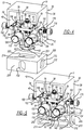
- Figure 1 is an isometric view and figure 2 is an exploded view of an expanding clamping twistlock 10 including a main body 12 that is a machined block of metal, such as steel, that includes various openings, shapes, surfaces, etc. to receive the various components and elements discussed herein.
- Figure 3 is a front view of the twistlock 10 with the main body 12 removed.
- the main body 12 has a general rectangular shape including a front wall 14, a back wall 16, side walls 18 and 20, a top rim 22 defining a recess 24 and a bottom wall, where an internal slot 26 is formed in the main body 12.
- the twistlock 10 also includes an upper housing 30 having a top wall 32, side walls 34 and 36, and a back wall 38 defining an enclosure 40, where the upper housing 30 is open to the bottom and front, as shown, and where the side walls 34 and 36 rest on the rim 22 where the upper housing 30 is secured to the main body 12.
- the twistlock 10 further includes a T-clamp screw 50 having a cylindrical body portion 52, an upper threaded portion 54 at the end of the body portion 52, a screw tip 56, and a transverse clamping portion 58 coupled to the body portion 52 opposite to the threaded portion 54.
- the cylindrical body portion 52 is inserted into an opening in the bottom wall of the main body 12 so that the tip 56 extends through the slot 26 and into the recess 24.
- a shelf plate 64 is positioned within the recess 24 so that the tip 56 of the screw 50 extends through an opening 66 in the plate 64, where the shelf plate 64 is bolted to a top surface within the recess 24 by bolts 68, as shown.
- a nut 70 is threaded onto the threaded portion 54 to hold the T-clamp screw 50 in place.
- the shelf plate 64 includes a pair of opposing spring wedges 72 and 74 extending from a bottom surface of the plate 64 and a pair of opposing side recesses 76 and 78 for reasons that will become apparent from the discussion below, where the wedges 72 and 74 extend into the slot 26.
- the body 12 includes a pair of side-by-side bores 80 and 82 that extend front-to-back through the front wall 14 and the back wall 16 of the housing 12, as shown.
- the twistlock 10 includes a first clamping cam toggle 90 having a central opening 92, a top cam portion 94 and a bottom cam portion 96, and a second clamping cam toggle 100 having a central opening 102, a top cam portion 104 and a bottom cam portion 106, where the cam toggles 90 and 100 are pivotally mounted within the slot 26 as discussed herein.
- a shaft 110 extends through the bore 80 and the opening 92 in the cam toggle 90, where the shaft 110 also extends through bronze bushings 112 and 114 provided within the bore 80 and positioned one on each side of the cam toggle 90.
- a stainless steel disc shim 116 and a stainless steel retaining ring 118 secure the shaft 110 to the body 12 at the back wall 16
- a stainless steel disc shim 120 and a stainless steel retaining ring 122 secure the shaft 110 to the body 12 at the front wall 14.
- a shaft 130 extends through the bore 82 and the opening 102 in the cam toggle 100, where the shaft 130 also extends through bronze bushings 132 and 134 provided within the bore 82 and positioned one on each side of the cam toggle 100.
- a stainless steel disc shim 136 and a stainless steel retaining ring 138 secure the shaft 130 to the body 12 at the back wall 16
- a stainless steel disc shim 140 and a stainless steel retaining ring 142 secure the shaft 130 to the body 12 at the front wall 14.
- the cam toggle 90 is pivoted on the shaft 110 by a toggle bolt 150 having a threaded portion 152, where the threaded portion 152 is threaded into a screw bushing 156 that is bolted to the side wall 18 by bolts 160.
- the threaded portion 152 extends through an opening 158 in the side wall 18 and engages the top cam portion 94 of the cam toggle 90, as shown.
- a conical return spring 170 is positioned between the cam portion 94 and the wedge 72 to push the cam toggle 90 back to a home position when the bolt 150 is unthreaded.
- the cam toggle 100 is pivoted on the shaft 130 by a toggle bolt 176 having a threaded portion 178, where the threaded portion 178 is threaded into a screw bushing 180 that is bolted to the side wall 20 by bolts 182.
- the threaded portion 178 extends through an opening 184 in the side wall 20 and engages the top cam portion 104 of the cam toggle 100, as shown.
- a conical return spring 186 is positioned between the cam portion 104 and the wedge 74 to push the cam toggle 100 back to a home position when the bolt 176 is unthreaded.
- a ball plunger 190 is threaded into an opening 192 in the front wall 14 of the housing 12 and engages a stop slot 194 in the body portion 52 of the T-clamp screw 50 that operates as a hard limit so as to limit the amount the T-clamp screw 50 can be rotated.
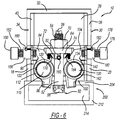
- the twistlock 10 is designed to engage and be locked to a corner fitting of the type referred to above.
- Figures 4 - 6 show the process of how the twistlock 10 is secured to a corner fitting 200 that could be, for example, provided at the corners of a shipping container or other structure.
- the corner fitting 200 can be provided in any suitable structure such as the deck of a ship.
- the corner fitting 200 includes a top ISO aperture 202 formed through a top wall 204 of the fitting 200, a side ISO aperture 206 formed through a side wall 208 of the fitting 200, and a side ISO aperture 210 formed through an end wall 212 of the fitting 200, where the apertures 202, 206 and 210 are open to a chamber 214 within the fitting 200.
- the corner fitting 200 is shown broken away in figures 5 and 6 to illustrate the chamber 214 in the fitting 200.
- the twistlock 10 is positioned relative to the corner fitting 200 so that the clamping portion 58 lines with up the aperture 202, as shown in figure 4 .
- the twistlock 10 is then moved downward to engage the corner fitting 200 so that the clamping portion 58 travels through the aperture 202 to be positioned within the chamber 214.
- a suitable wrench (not shown) is then used to engage the tip 56 through the open front of the upper housing 30 to rotate the T-clamp screw 50 and cause the clamping portion 58 to be substantially perpendicular to the length of the aperture 202, where the ball plunger 190 hits a hard stop defined by the stop slot 194 in the body portion 52 when the clamping portion 58 is properly positioned.
- Figure 4 shows the clamping portion 58 below the cam portions 96 and 106 of the cam toggles 90 and 100.
- the clamping portion 58 is able to be drawn up between the cam portions 96 and 106.
- the nut 70 is rotated on the threaded portion 58 generally using a suitable wrench (not shown) so that the clamping portion 58 is drawn up and clamps against an underside of the top wall 204. This provides rigidity in the up/down direction.
- a suitable wrench (not shown) is used to turn the bolts 150 and 176 to pivot the cam toggles 90 and 100 on the shafts 110 and 130, respectively, where the top cam portions 94 and 104 are pushed into the recesses 76 and 78 in the plate 64, which causes the bottom cam portions 96 and 106 to pivot away from the T-clamp screw 50 and engage inside edge portions of the opening 202 as shown in figure 6 , which provides stability of the twistlock 10 in a fore/aft orientation.
- the upper housing 30 can be coupled to any suitable structure, such as by welding, couplers, or the like, to connect the corner fitting 200 to other devices, such as other corner fittings, other twistlocks, etc., so as to secure the corner fitting to those devices.
Landscapes
- Engineering & Computer Science (AREA)
- Mechanical Engineering (AREA)
- Chemical & Material Sciences (AREA)
- Combustion & Propulsion (AREA)
- Ocean & Marine Engineering (AREA)
- Transportation (AREA)
- Clamps And Clips (AREA)
- Mutual Connection Of Rods And Tubes (AREA)
- Ladders (AREA)
Abstract
Description
- This application claims the benefit of the priority date of
U.S. Provisional Patent Application Serial No. 62/312,928 - This invention was made with Government support under contract N00024-15-C-6311 awarded by the Naval Sea Systems Command. The Government has certain rights in the invention.
- This invention relates generally to a twistlock and, more particularly, to an expanding clamping twistlock that has particular application for engaging an ISO aperture in a fitting, where the twistlock employs a system of screws and cams that secure a structure in both a fore/aft direction and a vertical direction.
- Massive container ships that are able to transport many shipping container across oceans and between countries generally define worldwide commerce. The shipping containers transported by these ships have a certain size, weight and configuration that are defined by the International Organization for Standardization (ISO). In order to comply with ISO requirements, the shipping containers include a corner fitting securely mounted to each of the eight corners of the container that allows the container to be lifted by a crane using suitable connecting mechanisms, such as hooks, and allow the shipping containers to be secured to the deck of the ship and to each other so that the containers can be stacked on the deck to a height that is often times breath taking. Each of the corner fittings includes specially configured slots or ISO apertures in the faces of the fitting directed outward, where each fitting will include a top or bottom aperture, a front or back aperture and a side aperture. Further, ISO apertures are generally provided at desirable locations in the deck of the ship. Other types of ships, such as various navy ships, also employ various types of fittings that have ISO apertures.
- Connectors are required to engage the ISO apertures in the corner fittings or otherwise so as to allow the containers to be secured to each other and to the deck of the ship in a manner that allows the containers to be reliably coupled together in the open sea. These connectors often employ a twistlock design where an engaging portion of the connector is inserted into the ISO aperture and is rotated to engage an underside surface within the fitting to secure the connector to the fitting. Various types of twistlock designs are known in the industry that operate in this manner.
- In many of these twistlock designs, the engaging portion of the twistlock has a size that is significantly smaller than the ISO aperture so that there is "play" in all directions after the twistlock is secured to the fitting, and thus, known twistlocks may not provide a tight fit between ISO apertures. For applications where twistlocks are used for securing a structure to the deck of a ship that may not be shipping containers, where multiple twistlocks may be employed to secure the structure, one or a few of the twistlocks may be carrying the entire load in these other directions, providing a recipe for failure. Therefore, it would be desirable to have a twistlock for securing shipping containers or other structures to the deck of a ship that eliminates play and provides a tight fit to evenly spread the load between fittings along all axes.
-
-
Figure 1 is an isometric view of an expanding clamping twistlock; -
Figure 2 is an exploded view of the expanding clamping twistlock shown infigure 1 ; -
Figure 3 is a front view of the expanding clamping twistlock shown infigure 1 with a main body removed; -
Figure 4 is an isometric view of the expanding clamping twistlock shown infigure 1 and being positioned relative to a corner fitting; -
Figure 5 is an isometric view of the expanding clamping twistlock being inserted into an ISO aperture of the corner fitting; and -
Figure 6 is an isometric view of the expanding clamping twistlock positioned within the corner fitting and being clamped thereto. - The following discussion of the embodiments of the invention directed to an expanding clamping twistlock is merely exemplary in nature, and is in no way intended to limit the invention or its applications or uses. For example, the twistlock of the invention as described herein will have particular application to be coupled to an ISO aperture of a corner fitting for a shipping container or other structure. However, the twistlock of the invention may have application to be coupled to other types of fittings.
-
Figure 1 is an isometric view andfigure 2 is an exploded view of an expandingclamping twistlock 10 including amain body 12 that is a machined block of metal, such as steel, that includes various openings, shapes, surfaces, etc. to receive the various components and elements discussed herein.Figure 3 is a front view of thetwistlock 10 with themain body 12 removed. Themain body 12 has a general rectangular shape including afront wall 14, aback wall 16,side walls top rim 22 defining arecess 24 and a bottom wall, where aninternal slot 26 is formed in themain body 12. Thetwistlock 10 also includes anupper housing 30 having atop wall 32,side walls back wall 38 defining anenclosure 40, where theupper housing 30 is open to the bottom and front, as shown, and where theside walls rim 22 where theupper housing 30 is secured to themain body 12. - The
twistlock 10 further includes a T-clamp screw 50 having acylindrical body portion 52, an upper threadedportion 54 at the end of thebody portion 52, ascrew tip 56, and atransverse clamping portion 58 coupled to thebody portion 52 opposite to the threadedportion 54. Thecylindrical body portion 52 is inserted into an opening in the bottom wall of themain body 12 so that thetip 56 extends through theslot 26 and into therecess 24. Ashelf plate 64 is positioned within therecess 24 so that thetip 56 of thescrew 50 extends through anopening 66 in theplate 64, where theshelf plate 64 is bolted to a top surface within therecess 24 bybolts 68, as shown. Anut 70 is threaded onto the threadedportion 54 to hold the T-clamp screw 50 in place. Theshelf plate 64 includes a pair ofopposing spring wedges plate 64 and a pair ofopposing side recesses wedges slot 26. - The
body 12 includes a pair of side-by-side bores front wall 14 and theback wall 16 of thehousing 12, as shown. Thetwistlock 10 includes a firstclamping cam toggle 90 having acentral opening 92, atop cam portion 94 and abottom cam portion 96, and a secondclamping cam toggle 100 having acentral opening 102, atop cam portion 104 and abottom cam portion 106, where thecam toggles slot 26 as discussed herein. Particularly, ashaft 110 extends through thebore 80 and the opening 92 in thecam toggle 90, where theshaft 110 also extends throughbronze bushings bore 80 and positioned one on each side of thecam toggle 90. A stainlesssteel disc shim 116 and a stainlesssteel retaining ring 118 secure theshaft 110 to thebody 12 at theback wall 16, and a stainlesssteel disc shim 120 and a stainlesssteel retaining ring 122 secure theshaft 110 to thebody 12 at thefront wall 14. Likewise, ashaft 130 extends through thebore 82 and the opening 102 in thecam toggle 100, where theshaft 130 also extends throughbronze bushings bore 82 and positioned one on each side of thecam toggle 100. A stainlesssteel disc shim 136 and a stainlesssteel retaining ring 138 secure theshaft 130 to thebody 12 at theback wall 16, and a stainlesssteel disc shim 140 and a stainlesssteel retaining ring 142 secure theshaft 130 to thebody 12 at thefront wall 14. - The
cam toggle 90 is pivoted on theshaft 110 by atoggle bolt 150 having a threadedportion 152, where the threadedportion 152 is threaded into a screw bushing 156 that is bolted to theside wall 18 bybolts 160. The threadedportion 152 extends through anopening 158 in theside wall 18 and engages thetop cam portion 94 of thecam toggle 90, as shown. Aconical return spring 170 is positioned between thecam portion 94 and thewedge 72 to push thecam toggle 90 back to a home position when thebolt 150 is unthreaded. Likewise, thecam toggle 100 is pivoted on theshaft 130 by atoggle bolt 176 having a threadedportion 178, where the threadedportion 178 is threaded into a screw bushing 180 that is bolted to theside wall 20 bybolts 182. The threadedportion 178 extends through anopening 184 in theside wall 20 and engages thetop cam portion 104 of thecam toggle 100, as shown. Aconical return spring 186 is positioned between thecam portion 104 and thewedge 74 to push thecam toggle 100 back to a home position when thebolt 176 is unthreaded. - A
ball plunger 190 is threaded into an opening 192 in thefront wall 14 of thehousing 12 and engages astop slot 194 in thebody portion 52 of the T-clamp screw 50 that operates as a hard limit so as to limit the amount the T-clamp screw 50 can be rotated. - The
twistlock 10 is designed to engage and be locked to a corner fitting of the type referred to above.Figures 4 - 6 show the process of how thetwistlock 10 is secured to a corner fitting 200 that could be, for example, provided at the corners of a shipping container or other structure. However, it is stressed that the corner fitting 200 can be provided in any suitable structure such as the deck of a ship. Thecorner fitting 200 includes a top ISOaperture 202 formed through atop wall 204 of thefitting 200, a side ISOaperture 206 formed through aside wall 208 of thefitting 200, and aside ISO aperture 210 formed through anend wall 212 of thefitting 200, where theapertures chamber 214 within thefitting 200. The corner fitting 200 is shown broken away infigures 5 and6 to illustrate thechamber 214 in thefitting 200. - The
twistlock 10 is positioned relative to the corner fitting 200 so that theclamping portion 58 lines with up theaperture 202, as shown infigure 4 . Thetwistlock 10 is then moved downward to engage the corner fitting 200 so that theclamping portion 58 travels through theaperture 202 to be positioned within thechamber 214. A suitable wrench (not shown) is then used to engage thetip 56 through the open front of theupper housing 30 to rotate the T-clamp screw 50 and cause theclamping portion 58 to be substantially perpendicular to the length of theaperture 202, where theball plunger 190 hits a hard stop defined by thestop slot 194 in thebody portion 52 when theclamping portion 58 is properly positioned.Figure 4 shows theclamping portion 58 below thecam portions cam toggles clamp screw 50 is turned when it is inside of thefitting 200, in the orientation as shown infigure 5 , theclamping portion 58 is able to be drawn up between thecam portions nut 70 is rotated on the threadedportion 58 generally using a suitable wrench (not shown) so that theclamping portion 58 is drawn up and clamps against an underside of thetop wall 204. This provides rigidity in the up/down direction. Once in this position, a suitable wrench (not shown) is used to turn thebolts shafts top cam portions recesses plate 64, which causes thebottom cam portions clamp screw 50 and engage inside edge portions of theopening 202 as shown infigure 6 , which provides stability of thetwistlock 10 in a fore/aft orientation. - The
upper housing 30 can be coupled to any suitable structure, such as by welding, couplers, or the like, to connect the corner fitting 200 to other devices, such as other corner fittings, other twistlocks, etc., so as to secure the corner fitting to those devices. - The foregoing discussion discloses and describes merely exemplary embodiments of the present invention. One skilled in the art will readily recognize from such discussion and from the accompanying drawings and claims that various changes, modifications and variations can be made therein without departing from the spirit and scope of the invention as defined in the following claims.
Claims (20)
- A twistlock comprising:a main body including a front wall, a back wall, opposing side walls and a bottom wall, said body further including an internal slot and first and second bores extending through the body from the front wall to the back wall and through the slot;a first shaft extending through the first bore and a second shaft extending through the second bore;a first clamping cam toggle including an opening through which the first shaft extends, said first cam toggle being positioned in the slot;a second clamping cam toggle including an opening through which the second shaft extends, said second cam toggle being positioned in the slot;a T-clamp screw including a body portion, a threaded end portion at one end of the body portion, and a clamping portion at an opposite end of the body portion, said body portion extending through an opening in the main body and through the slot between the first and second cam toggles so that the clamping portion is positioned adjacent to an outside of the bottom wall of the main body; anda first toggle bolt extending through one of the side walls of the main body and engaging the first cam toggle and a second toggle bolt extending through the other side wall of the main body and engaging the second cam toggle, wherein the T-clamp screw is rotatable to engage an underside of a wall in a fitting and the first and second toggle bolts are operable to toggle the first and second cam toggles to engage edges of an aperture in the fitting through which the T-clamp screw extends.
- The twistlock according to claim 1 wherein the fitting is a corner fitting having apertures defined by the International Organization for Standardization (ISO).
- The twistlock according to claim 2 wherein the corner fitting is mounted in a deck of a ship or is mounted to a corner of a shipping container.
- The twistlock according to claim 1 wherein the main body includes an upper rim opposite to the bottom wall and defining a recess therein where the threaded end portion of the T-clamp screw is positioned.
- The twistlock according to claim 4 further comprising an upper housing including opposing side walls, a back wall and a top wall configured so that the upper housing an opening towards a front of the main body and to the recess such that the side walls and back wall of the upper housing are positioned on the upper rim so as to allow a nut threaded onto the threaded end portion to be accessible through the opening.
- The twistlock according to claim 5 further comprising a shelf plate secured to the main body in the recess, said shelf plate including a central opening through which the threaded end portion of the T-clamp screw extends and having a top surface to which the nut rests on.
- The twistlock according to claim 6 wherein the shelf plate includes opposing side recesses that each receive a top cam portion of the first or second cam toggle when the first and second toggle bolts toggle the first and second cam toggles.
- The twistlock according to claim 7 further comprising first and second return springs, said shelf plate further including first and second wedges secured to a bottom surface of the shelf plate and extending into the slot, said first spring engaging the first wedge and the top cam portion of the first cam toggle and said second spring engaging the second wedge and the top cam portion of the second cam toggle so as to return the first and second cam toggles to a home position when the first and second toggle bolts are retracted.
- The twistlock according to claim 1 further comprising a ball plunger threaded through the front wall of the main body, said body portion of the T-clamp screw including a stop slot that engage the ball plunger and prevents the T-clamp screw from being rotated beyond a predetermined position.
- The twistlock according to claim 1 wherein the T-clamp screw further includes a screw tip at an end of the threaded portion opposite to the clamping portion that is operable to rotate the T-clamp screw between an insertion position and a clamping position.
- A twistlock for securing to a fitting having an aperture defined by the International Organization for Standardization (ISO), said twistlock comprising:a main body including a front wall, a back wall, opposing side walls and a bottom wall;a first clamping cam toggle pivotally mounted within the main body;a second clamping cam toggle pivotally mounted within the main body; anda T-clamp screw including a body portion, a threaded end portion at one end of the body portion and a clamping portion at an opposite end of the body portion, said body portion extending through an opening in the main body and between the first and second cam toggles so that the clamping portion is positioned adjacent to an outside of the bottom wall of the main body, wherein the T-clamp screw is rotatable to engage an underside of a wall in the fitting and the first and second cam toggles are pivotable to engage edges of the aperture in the fitting.
- The twistlock according to claim 11 further comprising a first toggle bolt extending through one of the side walls of the main body and engaging the first cam toggle and a second toggle bolt extending through the other side wall of the main body and engaging the second cam toggle, wherein the first and second toggle bolts are operable to toggle the first and second cam toggles to engage edges of the aperture in the fitting through which the T-clamp screw extends.
- The twistlock according to claim 11 wherein the main body includes an upper rim opposite to the bottom wall and defining a recess therein where the threaded end portion of the T-clamp screw is positioned.
- The twistlock according to claim 13 further comprising an upper housing including opposing side walls, a back wall and a top wall configured so that the upper housing has an opening towards a front of the main body and to the recess such that the side walls and back wall of the upper housing are positioned on the upper rim so as to allow a nut threaded onto the threaded end portion to be accessible through the opening.
- The twistlock according to claim 14 further comprising a shelf plate secured to the main body in the recess, said shelf plate including a central opening through which the threaded end portion of the T-clamp screw extends and having a top surface to which the nut rests on.
- The twistlock according to claim 15 wherein the shelf plate includes opposing side recesses that each receive a top cam portion of the first or second cam toggle.
- The twistlock according to claim 16 further comprising first and second return springs, said shelf plate further including first and second wedges secured to a bottom surface of the shelf plate, said first spring engaging the first wedge and the top cam portion of the first cam toggle and said second spring engaging the second wedge and the top cam portion of the second cam toggle so as to return the first and second cam toggles to a home position.
- The twistlock according to claim 11 further comprising a ball plunger threaded through the front wall of the main body, said body portion of the T-clamp screw including a stop slot that engages the ball plunger and prevents the T-clamp screw from being rotated beyond a predetermined position.
- A twistlock for securing to a fitting having an aperture defined by the International Organization for Standardization (ISO), said twistlock comprising:a main body including a front wall, a back wall, opposing side walls and a bottom wall, said body further including an internal slot and first and second bores extending through the body from the front wall to the back wall and through the slot;a first shaft extending through the first bore and a second shaft extending through the second bore;a first clamping cam toggle including an opening through which the first shaft extends, said first cam toggle being positioned in the slot;a second clamping cam toggle including an opening through which the second shaft extends, said second cam toggle being positioned in the slot;a T-clamp screw including a body portion, a threaded end portion at one end of the body portion, and a clamping portion at an opposite end of the body portion, said body portion extending through an opening in the main body and through the slot between the first and second cam toggles so that the clamping portion is positioned adjacent to an outside of the bottom wall of the main body, wherein the main body includes an upper rim opposite to the bottom wall and defining a recess therein where the threaded end portion of the T-clamp screw is positioned;an upper housing including opposing side walls, a back wall and a top wall configured so that the upper housing has an opening towards a front of the main body and to the recess such that the side walls and back wall of the upper housing are positioned on the upper rim so as to allow a nut threaded onto the threaded end portion to be accessible through the opening;a shelf plate secured to the main body in the recess, said shelf plate including a central opening through which the threaded end portion of the T-clamp screw extends and having a top surface to which the nut rests on;a first toggle bolt extending through one of the side walls of the main body and engaging the first cam toggle and a second toggle bolt extending through the other side wall of the main body and engaging the second cam toggle, wherein the T-clamp screw is rotatable to engage an underside of a wall in the fitting and the first and second toggle bolts are operable to toggle the first and second cam toggles to engage edges of the aperture in the fitting through which the T-clamp screw extends, wherein the shelf plate includes opposing side recesses that each receive a top cam portion of the first or second cam toggle when the first and second toggle bolts toggle the first and second cam toggles; andfirst and second return springs, said shelf plate further including first and second wedges secured to a bottom surface of the shelf plate and extending into the slot, said first spring engaging the first wedge and the top cam portion of the first cam toggle and said second spring engaging the second wedge and the top cam portion of the second cam toggle so as to return the first and second cam toggles to a home position when the first and second toggle bolts are retracted.
- The twistlock according to claim 19 wherein the fitting is mounted in a deck of a ship or is mounted to a corner of a shipping container.
Applications Claiming Priority (2)
| Application Number | Priority Date | Filing Date | Title |
|---|---|---|---|
| US201662312928P | 2016-03-24 | 2016-03-24 | |
| US15/199,521 US9663021B1 (en) | 2016-03-24 | 2016-06-30 | Expanding clamping twistlock for ISO aperture securement |
Publications (3)
| Publication Number | Publication Date |
|---|---|
| EP3222559A2 true EP3222559A2 (en) | 2017-09-27 |
| EP3222559A3 EP3222559A3 (en) | 2017-12-13 |
| EP3222559B1 EP3222559B1 (en) | 2019-01-09 |
Family
ID=58738512
Family Applications (1)
| Application Number | Title | Priority Date | Filing Date |
|---|---|---|---|
| EP17000414.7A Active EP3222559B1 (en) | 2016-03-24 | 2017-03-14 | Expanding clamping twistlock for iso aperture securement |
Country Status (2)
| Country | Link |
|---|---|
| US (1) | US9663021B1 (en) |
| EP (1) | EP3222559B1 (en) |
Families Citing this family (1)
| Publication number | Priority date | Publication date | Assignee | Title |
|---|---|---|---|---|
| DE102024113046B4 (en) * | 2024-05-08 | 2026-03-05 | Kugelmann Maschinenbau E.K. | Load securing system |
Family Cites Families (27)
| Publication number | Priority date | Publication date | Assignee | Title |
|---|---|---|---|---|
| US3367615A (en) | 1966-01-19 | 1968-02-06 | Russell L. Turpen | Universal bolster |
| US3578374A (en) | 1969-05-22 | 1971-05-11 | Pullman Inc | Container coupler arrangement |
| US3825294A (en) | 1972-01-21 | 1974-07-23 | Pullman Inc | Twist lock arrangement for tying container down |
| US3972439A (en) | 1974-06-05 | 1976-08-03 | Dimartino John M | Horizontal connector for shipping containers |
| US3906870A (en) | 1974-06-24 | 1975-09-23 | Boeing Co | Retractable cargo restraint and center guide for cargo compartments |
| US3989294A (en) | 1975-10-24 | 1976-11-02 | Pullman Incorporated | Twist lock arrangement for tying container down |
| GB2070125A (en) * | 1980-02-01 | 1981-09-03 | Rubery Owen Rockwell Ltd | Improvements in twistlocks for mounting freight containers on trailers and other vehicles |
| EP0228358B1 (en) * | 1985-12-30 | 1990-02-07 | Europe Trailer Components | Device for locking a container on a mobile element |
| US4844672A (en) | 1988-04-20 | 1989-07-04 | Rosby Corporation | Interlocking adapter casting |
| US5106247A (en) * | 1990-08-09 | 1992-04-21 | Johan Hove | Automatic locking system |
| US5454673A (en) | 1993-11-01 | 1995-10-03 | Dimartino; John M. | Horizontal connector for shipping containers |
| DE29701977U1 (en) * | 1997-02-05 | 1997-06-12 | Schulz, Frank P., 31737 Rinteln | Locking nut for locking the lock of a container or swap body |
| DE19816892C2 (en) | 1998-04-16 | 2000-05-18 | Telair Int Gmbh | bars |
| WO2000023358A1 (en) | 1998-10-19 | 2000-04-27 | Kabushiki Kaisha Marifit | Container connector |
| DE10032566A1 (en) | 2000-04-06 | 2002-01-17 | Horst Neufingerl | Automatically detachable connection assembly, in particular for connecting two sea freight containers arranged one above the other |
| US6490766B1 (en) | 2000-09-25 | 2002-12-10 | Peck & Hale Llc | Coupling device including automatic latching lock |
| GB0321782D0 (en) | 2003-09-17 | 2003-10-15 | Smith Martin C | Demountable stub post |
| US7484918B2 (en) * | 2006-03-10 | 2009-02-03 | John Basco Brewster | Container securement device and system |
| NL1031973C2 (en) | 2006-06-09 | 2007-12-11 | Logi D B V | Locking device. |
| US7637704B2 (en) | 2007-01-11 | 2009-12-29 | Portec Rail Products Inc. | Railcar container lock providing automatic locking and unlocking |
| KR101517404B1 (en) | 2008-09-08 | 2015-05-06 | 박재욱 | Method of securing freight containers on deck of ship, and spring lashing bar, space adjuster and securing system used in the method |
| FI124181B (en) | 2008-09-16 | 2014-04-15 | Macgregor Fin Oy | Coupling means for coupling containers, in particular containers used on cargo ships |
| US7942282B2 (en) | 2008-10-10 | 2011-05-17 | Universal Global Investment Co., Ltd. | Retainer for shipping containers |
| DE202010005717U1 (en) | 2010-06-25 | 2011-09-30 | Rmm Metternich Mechatronik Gmbh | Locking device for containers |
| JP5876159B2 (en) * | 2011-11-10 | 2016-03-02 | 三星重工業株式会社Samsungheavy Ind.Co.,Ltd. | Container fixing device |
| DE202012102343U1 (en) | 2012-06-26 | 2012-07-18 | Rmm Metternich Mechatronik Gmbh | locking device |
| US9011055B1 (en) | 2013-08-05 | 2015-04-21 | Peck & Hale, L.L.C. | Automatic lock for cargo container |
-
2016
- 2016-06-30 US US15/199,521 patent/US9663021B1/en active Active
-
2017
- 2017-03-14 EP EP17000414.7A patent/EP3222559B1/en active Active
Non-Patent Citations (1)
| Title |
|---|
| None |
Also Published As
| Publication number | Publication date |
|---|---|
| US9663021B1 (en) | 2017-05-30 |
| EP3222559B1 (en) | 2019-01-09 |
| EP3222559A3 (en) | 2017-12-13 |
Similar Documents
| Publication | Publication Date | Title |
|---|---|---|
| EP1893508B1 (en) | Fully automatic twistlock | |
| DK2423046T3 (en) | A device for attaching the heavy loads | |
| US9561567B2 (en) | Workpiece holding device | |
| US11009055B2 (en) | Robust adjustable panel insert | |
| US20150345536A1 (en) | Cage nut | |
| US10340624B2 (en) | Retaining frame | |
| EP3293128A1 (en) | Container binding device | |
| US9663021B1 (en) | Expanding clamping twistlock for ISO aperture securement | |
| US12304692B1 (en) | Storage box | |
| US4768905A (en) | Apparatus for securing containers end to end | |
| US10398053B2 (en) | Equipment clamping assembly having horizontal and vertical clamps for use in rugged and other environments | |
| CN107532752A (en) | The obvious stopper section of compression wedge part | |
| EP2669208A1 (en) | A clamp | |
| US3972439A (en) | Horizontal connector for shipping containers | |
| CN105697480A (en) | Pressing-plate-type locker | |
| US20180177066A1 (en) | Equipment clamping assembly using clamps and friction to secure equipment for use in rugged and other environments | |
| JP2020111319A (en) | Coupling component for connecting two containers stacked on top of each other on vessel | |
| CN106715051B (en) | Clamping system using wedges for use with angle drives | |
| US20170125936A1 (en) | Retaining frame for plug-connector modules and/or plug connectors | |
| US20160376081A1 (en) | Packing case | |
| CN208619499U (en) | Nut and nut mounting structure | |
| EP1805077B1 (en) | Lashing device comprising a coupling device with snap action | |
| KR20140006209U (en) | Dummy apparatus for installing a pump | |
| US9035728B2 (en) | Electromagnetic interface secured by using an indirect compression force to slidably engage first and second force transfer features | |
| US20120031222A1 (en) | Anti-backlash device |
Legal Events
| Date | Code | Title | Description |
|---|---|---|---|
| PUAI | Public reference made under article 153(3) epc to a published international application that has entered the european phase |
Free format text: ORIGINAL CODE: 0009012 |
|
| STAA | Information on the status of an ep patent application or granted ep patent |
Free format text: STATUS: THE APPLICATION HAS BEEN PUBLISHED |
|
| AK | Designated contracting states |
Kind code of ref document: A2 Designated state(s): AL AT BE BG CH CY CZ DE DK EE ES FI FR GB GR HR HU IE IS IT LI LT LU LV MC MK MT NL NO PL PT RO RS SE SI SK SM TR |
|
| AX | Request for extension of the european patent |
Extension state: BA ME |
|
| PUAL | Search report despatched |
Free format text: ORIGINAL CODE: 0009013 |
|
| AK | Designated contracting states |
Kind code of ref document: A3 Designated state(s): AL AT BE BG CH CY CZ DE DK EE ES FI FR GB GR HR HU IE IS IT LI LT LU LV MC MK MT NL NO PL PT RO RS SE SI SK SM TR |
|
| AX | Request for extension of the european patent |
Extension state: BA ME |
|
| RIC1 | Information provided on ipc code assigned before grant |
Ipc: B61D 45/00 20060101ALI20171108BHEP Ipc: B60P 7/13 20060101ALI20171108BHEP Ipc: B63B 25/00 20060101ALI20171108BHEP Ipc: B65D 90/00 20060101AFI20171108BHEP |
|
| STAA | Information on the status of an ep patent application or granted ep patent |
Free format text: STATUS: REQUEST FOR EXAMINATION WAS MADE |
|
| 17P | Request for examination filed |
Effective date: 20180607 |
|
| RBV | Designated contracting states (corrected) |
Designated state(s): AL AT BE BG CH CY CZ DE DK EE ES FI FR GB GR HR HU IE IS IT LI LT LU LV MC MK MT NL NO PL PT RO RS SE SI SK SM TR |
|
| GRAP | Despatch of communication of intention to grant a patent |
Free format text: ORIGINAL CODE: EPIDOSNIGR1 |
|
| STAA | Information on the status of an ep patent application or granted ep patent |
Free format text: STATUS: GRANT OF PATENT IS INTENDED |
|
| RIC1 | Information provided on ipc code assigned before grant |
Ipc: B65D 90/00 20060101AFI20180703BHEP Ipc: B61D 45/00 20060101ALI20180703BHEP Ipc: B60P 7/13 20060101ALI20180703BHEP Ipc: B63B 25/28 20060101ALI20180703BHEP Ipc: B63B 25/00 20060101ALI20180703BHEP Ipc: B63B 25/24 20060101ALI20180703BHEP |
|
| INTG | Intention to grant announced |
Effective date: 20180808 |
|
| GRAS | Grant fee paid |
Free format text: ORIGINAL CODE: EPIDOSNIGR3 |
|
| GRAA | (expected) grant |
Free format text: ORIGINAL CODE: 0009210 |
|
| STAA | Information on the status of an ep patent application or granted ep patent |
Free format text: STATUS: THE PATENT HAS BEEN GRANTED |
|
| AK | Designated contracting states |
Kind code of ref document: B1 Designated state(s): AL AT BE BG CH CY CZ DE DK EE ES FI FR GB GR HR HU IE IS IT LI LT LU LV MC MK MT NL NO PL PT RO RS SE SI SK SM TR |
|
| REG | Reference to a national code |
Ref country code: GB Ref legal event code: FG4D |
|
| REG | Reference to a national code |
Ref country code: CH Ref legal event code: EP Ref country code: AT Ref legal event code: REF Ref document number: 1087024 Country of ref document: AT Kind code of ref document: T Effective date: 20190115 |
|
| REG | Reference to a national code |
Ref country code: IE Ref legal event code: FG4D |
|
| REG | Reference to a national code |
Ref country code: DE Ref legal event code: R096 Ref document number: 602017001719 Country of ref document: DE |
|
| REG | Reference to a national code |
Ref country code: NL Ref legal event code: MP Effective date: 20190109 |
|
| REG | Reference to a national code |
Ref country code: LT Ref legal event code: MG4D |
|
| PG25 | Lapsed in a contracting state [announced via postgrant information from national office to epo] |
Ref country code: NL Free format text: LAPSE BECAUSE OF FAILURE TO SUBMIT A TRANSLATION OF THE DESCRIPTION OR TO PAY THE FEE WITHIN THE PRESCRIBED TIME-LIMIT Effective date: 20190109 |
|
| REG | Reference to a national code |
Ref country code: AT Ref legal event code: MK05 Ref document number: 1087024 Country of ref document: AT Kind code of ref document: T Effective date: 20190109 |
|
| PG25 | Lapsed in a contracting state [announced via postgrant information from national office to epo] |
Ref country code: PT Free format text: LAPSE BECAUSE OF FAILURE TO SUBMIT A TRANSLATION OF THE DESCRIPTION OR TO PAY THE FEE WITHIN THE PRESCRIBED TIME-LIMIT Effective date: 20190509 Ref country code: SE Free format text: LAPSE BECAUSE OF FAILURE TO SUBMIT A TRANSLATION OF THE DESCRIPTION OR TO PAY THE FEE WITHIN THE PRESCRIBED TIME-LIMIT Effective date: 20190109 Ref country code: FI Free format text: LAPSE BECAUSE OF FAILURE TO SUBMIT A TRANSLATION OF THE DESCRIPTION OR TO PAY THE FEE WITHIN THE PRESCRIBED TIME-LIMIT Effective date: 20190109 Ref country code: NO Free format text: LAPSE BECAUSE OF FAILURE TO SUBMIT A TRANSLATION OF THE DESCRIPTION OR TO PAY THE FEE WITHIN THE PRESCRIBED TIME-LIMIT Effective date: 20190409 Ref country code: PL Free format text: LAPSE BECAUSE OF FAILURE TO SUBMIT A TRANSLATION OF THE DESCRIPTION OR TO PAY THE FEE WITHIN THE PRESCRIBED TIME-LIMIT Effective date: 20190109 Ref country code: LT Free format text: LAPSE BECAUSE OF FAILURE TO SUBMIT A TRANSLATION OF THE DESCRIPTION OR TO PAY THE FEE WITHIN THE PRESCRIBED TIME-LIMIT Effective date: 20190109 Ref country code: ES Free format text: LAPSE BECAUSE OF FAILURE TO SUBMIT A TRANSLATION OF THE DESCRIPTION OR TO PAY THE FEE WITHIN THE PRESCRIBED TIME-LIMIT Effective date: 20190109 |
|
| PG25 | Lapsed in a contracting state [announced via postgrant information from national office to epo] |
Ref country code: IS Free format text: LAPSE BECAUSE OF FAILURE TO SUBMIT A TRANSLATION OF THE DESCRIPTION OR TO PAY THE FEE WITHIN THE PRESCRIBED TIME-LIMIT Effective date: 20190509 Ref country code: HR Free format text: LAPSE BECAUSE OF FAILURE TO SUBMIT A TRANSLATION OF THE DESCRIPTION OR TO PAY THE FEE WITHIN THE PRESCRIBED TIME-LIMIT Effective date: 20190109 Ref country code: LV Free format text: LAPSE BECAUSE OF FAILURE TO SUBMIT A TRANSLATION OF THE DESCRIPTION OR TO PAY THE FEE WITHIN THE PRESCRIBED TIME-LIMIT Effective date: 20190109 Ref country code: RS Free format text: LAPSE BECAUSE OF FAILURE TO SUBMIT A TRANSLATION OF THE DESCRIPTION OR TO PAY THE FEE WITHIN THE PRESCRIBED TIME-LIMIT Effective date: 20190109 Ref country code: GR Free format text: LAPSE BECAUSE OF FAILURE TO SUBMIT A TRANSLATION OF THE DESCRIPTION OR TO PAY THE FEE WITHIN THE PRESCRIBED TIME-LIMIT Effective date: 20190410 Ref country code: BG Free format text: LAPSE BECAUSE OF FAILURE TO SUBMIT A TRANSLATION OF THE DESCRIPTION OR TO PAY THE FEE WITHIN THE PRESCRIBED TIME-LIMIT Effective date: 20190409 |
|
| REG | Reference to a national code |
Ref country code: DE Ref legal event code: R097 Ref document number: 602017001719 Country of ref document: DE |
|
| PG25 | Lapsed in a contracting state [announced via postgrant information from national office to epo] |
Ref country code: RO Free format text: LAPSE BECAUSE OF FAILURE TO SUBMIT A TRANSLATION OF THE DESCRIPTION OR TO PAY THE FEE WITHIN THE PRESCRIBED TIME-LIMIT Effective date: 20190109 Ref country code: IT Free format text: LAPSE BECAUSE OF FAILURE TO SUBMIT A TRANSLATION OF THE DESCRIPTION OR TO PAY THE FEE WITHIN THE PRESCRIBED TIME-LIMIT Effective date: 20190109 Ref country code: EE Free format text: LAPSE BECAUSE OF FAILURE TO SUBMIT A TRANSLATION OF THE DESCRIPTION OR TO PAY THE FEE WITHIN THE PRESCRIBED TIME-LIMIT Effective date: 20190109 Ref country code: CZ Free format text: LAPSE BECAUSE OF FAILURE TO SUBMIT A TRANSLATION OF THE DESCRIPTION OR TO PAY THE FEE WITHIN THE PRESCRIBED TIME-LIMIT Effective date: 20190109 Ref country code: AT Free format text: LAPSE BECAUSE OF FAILURE TO SUBMIT A TRANSLATION OF THE DESCRIPTION OR TO PAY THE FEE WITHIN THE PRESCRIBED TIME-LIMIT Effective date: 20190109 Ref country code: DK Free format text: LAPSE BECAUSE OF FAILURE TO SUBMIT A TRANSLATION OF THE DESCRIPTION OR TO PAY THE FEE WITHIN THE PRESCRIBED TIME-LIMIT Effective date: 20190109 Ref country code: MC Free format text: LAPSE BECAUSE OF FAILURE TO SUBMIT A TRANSLATION OF THE DESCRIPTION OR TO PAY THE FEE WITHIN THE PRESCRIBED TIME-LIMIT Effective date: 20190109 Ref country code: AL Free format text: LAPSE BECAUSE OF FAILURE TO SUBMIT A TRANSLATION OF THE DESCRIPTION OR TO PAY THE FEE WITHIN THE PRESCRIBED TIME-LIMIT Effective date: 20190109 Ref country code: SK Free format text: LAPSE BECAUSE OF FAILURE TO SUBMIT A TRANSLATION OF THE DESCRIPTION OR TO PAY THE FEE WITHIN THE PRESCRIBED TIME-LIMIT Effective date: 20190109 |
|
| PLBE | No opposition filed within time limit |
Free format text: ORIGINAL CODE: 0009261 |
|
| STAA | Information on the status of an ep patent application or granted ep patent |
Free format text: STATUS: NO OPPOSITION FILED WITHIN TIME LIMIT |
|
| PG25 | Lapsed in a contracting state [announced via postgrant information from national office to epo] |
Ref country code: LU Free format text: LAPSE BECAUSE OF NON-PAYMENT OF DUE FEES Effective date: 20190314 |
|
| REG | Reference to a national code |
Ref country code: BE Ref legal event code: MM Effective date: 20190331 |
|
| 26N | No opposition filed |
Effective date: 20191010 |
|
| PG25 | Lapsed in a contracting state [announced via postgrant information from national office to epo] |
Ref country code: IE Free format text: LAPSE BECAUSE OF NON-PAYMENT OF DUE FEES Effective date: 20190314 |
|
| PG25 | Lapsed in a contracting state [announced via postgrant information from national office to epo] |
Ref country code: SI Free format text: LAPSE BECAUSE OF FAILURE TO SUBMIT A TRANSLATION OF THE DESCRIPTION OR TO PAY THE FEE WITHIN THE PRESCRIBED TIME-LIMIT Effective date: 20190109 Ref country code: BE Free format text: LAPSE BECAUSE OF NON-PAYMENT OF DUE FEES Effective date: 20190331 |
|
| PG25 | Lapsed in a contracting state [announced via postgrant information from national office to epo] |
Ref country code: TR Free format text: LAPSE BECAUSE OF FAILURE TO SUBMIT A TRANSLATION OF THE DESCRIPTION OR TO PAY THE FEE WITHIN THE PRESCRIBED TIME-LIMIT Effective date: 20190109 |
|
| PG25 | Lapsed in a contracting state [announced via postgrant information from national office to epo] |
Ref country code: MT Free format text: LAPSE BECAUSE OF NON-PAYMENT OF DUE FEES Effective date: 20190314 |
|
| REG | Reference to a national code |
Ref country code: CH Ref legal event code: PL |
|
| PG25 | Lapsed in a contracting state [announced via postgrant information from national office to epo] |
Ref country code: LI Free format text: LAPSE BECAUSE OF NON-PAYMENT OF DUE FEES Effective date: 20200331 Ref country code: CH Free format text: LAPSE BECAUSE OF NON-PAYMENT OF DUE FEES Effective date: 20200331 |
|
| PG25 | Lapsed in a contracting state [announced via postgrant information from national office to epo] |
Ref country code: CY Free format text: LAPSE BECAUSE OF FAILURE TO SUBMIT A TRANSLATION OF THE DESCRIPTION OR TO PAY THE FEE WITHIN THE PRESCRIBED TIME-LIMIT Effective date: 20190109 |
|
| PG25 | Lapsed in a contracting state [announced via postgrant information from national office to epo] |
Ref country code: SM Free format text: LAPSE BECAUSE OF FAILURE TO SUBMIT A TRANSLATION OF THE DESCRIPTION OR TO PAY THE FEE WITHIN THE PRESCRIBED TIME-LIMIT Effective date: 20190109 |
|
| PG25 | Lapsed in a contracting state [announced via postgrant information from national office to epo] |
Ref country code: HU Free format text: LAPSE BECAUSE OF FAILURE TO SUBMIT A TRANSLATION OF THE DESCRIPTION OR TO PAY THE FEE WITHIN THE PRESCRIBED TIME-LIMIT; INVALID AB INITIO Effective date: 20170314 |
|
| GBPC | Gb: european patent ceased through non-payment of renewal fee |
Effective date: 20210314 |
|
| PG25 | Lapsed in a contracting state [announced via postgrant information from national office to epo] |
Ref country code: GB Free format text: LAPSE BECAUSE OF NON-PAYMENT OF DUE FEES Effective date: 20210314 |
|
| PG25 | Lapsed in a contracting state [announced via postgrant information from national office to epo] |
Ref country code: MK Free format text: LAPSE BECAUSE OF FAILURE TO SUBMIT A TRANSLATION OF THE DESCRIPTION OR TO PAY THE FEE WITHIN THE PRESCRIBED TIME-LIMIT Effective date: 20190109 |
|
| P01 | Opt-out of the competence of the unified patent court (upc) registered |
Effective date: 20230607 |
|
| PGFP | Annual fee paid to national office [announced via postgrant information from national office to epo] |
Ref country code: DE Payment date: 20260319 Year of fee payment: 10 |
|
| PGFP | Annual fee paid to national office [announced via postgrant information from national office to epo] |
Ref country code: FR Payment date: 20260320 Year of fee payment: 10 |