US9035728B2 - Electromagnetic interface secured by using an indirect compression force to slidably engage first and second force transfer features - Google Patents
Electromagnetic interface secured by using an indirect compression force to slidably engage first and second force transfer features Download PDFInfo
- Publication number
- US9035728B2 US9035728B2 US13/801,078 US201313801078A US9035728B2 US 9035728 B2 US9035728 B2 US 9035728B2 US 201313801078 A US201313801078 A US 201313801078A US 9035728 B2 US9035728 B2 US 9035728B2
- Authority
- US
- United States
- Prior art keywords
- force
- force transfer
- interface
- waveguide
- component
- Prior art date
- Legal status (The legal status is an assumption and is not a legal conclusion. Google has not performed a legal analysis and makes no representation as to the accuracy of the status listed.)
- Active, expires
Links
Images


Classifications
-
- H—ELECTRICITY
- H01—ELECTRIC ELEMENTS
- H01P—WAVEGUIDES; RESONATORS, LINES, OR OTHER DEVICES OF THE WAVEGUIDE TYPE
- H01P5/00—Coupling devices of the waveguide type
-
- H—ELECTRICITY
- H01—ELECTRIC ELEMENTS
- H01P—WAVEGUIDES; RESONATORS, LINES, OR OTHER DEVICES OF THE WAVEGUIDE TYPE
- H01P1/00—Auxiliary devices
- H01P1/04—Fixed joints
- H01P1/042—Hollow waveguide joints
-
- H—ELECTRICITY
- H01—ELECTRIC ELEMENTS
- H01P—WAVEGUIDES; RESONATORS, LINES, OR OTHER DEVICES OF THE WAVEGUIDE TYPE
- H01P11/00—Apparatus or processes specially adapted for manufacturing waveguides or resonators, lines, or other devices of the waveguide type
- H01P11/001—Manufacturing waveguides or transmission lines of the waveguide type
-
- H—ELECTRICITY
- H01—ELECTRIC ELEMENTS
- H01P—WAVEGUIDES; RESONATORS, LINES, OR OTHER DEVICES OF THE WAVEGUIDE TYPE
- H01P5/00—Coupling devices of the waveguide type
- H01P5/02—Coupling devices of the waveguide type with invariable factor of coupling
- H01P5/022—Transitions between lines of the same kind and shape, but with different dimensions
- H01P5/024—Transitions between lines of the same kind and shape, but with different dimensions between hollow waveguides
-
- Y—GENERAL TAGGING OF NEW TECHNOLOGICAL DEVELOPMENTS; GENERAL TAGGING OF CROSS-SECTIONAL TECHNOLOGIES SPANNING OVER SEVERAL SECTIONS OF THE IPC; TECHNICAL SUBJECTS COVERED BY FORMER USPC CROSS-REFERENCE ART COLLECTIONS [XRACs] AND DIGESTS
- Y10—TECHNICAL SUBJECTS COVERED BY FORMER USPC
- Y10T—TECHNICAL SUBJECTS COVERED BY FORMER US CLASSIFICATION
- Y10T29/00—Metal working
- Y10T29/49—Method of mechanical manufacture
- Y10T29/49002—Electrical device making
- Y10T29/49016—Antenna or wave energy "plumbing" making
Definitions
- This application is relevant to the field of radio frequency waveguide interface technology, and particularly to low voltage standing wave ratio interfaces.
- an RF waveguide in a first metal piece can be connected to an RF waveguide in a second metal piece.
- the connection can also be described as an electromagnetic interface. It may be desirable that this electromagnetic interface be a low Voltage Standing Wave Ratio (“VSWR”) interface. In order to have such a low VSWR interface, it can be advantageous to have uniform contact between the interfacing surfaces of the two metal pieces.
- VSWR Voltage Standing Wave Ratio
- an electromagnetic interface can be formed between a first metal piece 110 and a second metal piece 120 .
- the first metal piece can more generally be a component
- the second metal piece can more generally be a component, to the extent that these components each comprise a waveguide channel.
- an electromagnetic interface can be formed between a first component 110 and a second component 120 .
- the electromagnetic interface between pieces 110 and 120 defines an interface plane.
- First metal piece 110 can comprise a waveguide channel 112 aligned in a first direction that can be perpendicular to the interface plane.
- the second metal piece 120 can comprise a waveguide channel 122 aligned in the first direction as well.
- the waveguide channels 112 and 122 can be aligned with each other.
- the first and second metal pieces can be held together by two or more screws 130 that pass through the first metal piece and screw into the second metal piece to keep the two metal pieces in tight contact one with another. In this manner, the two wave guide pieces can be directly fastened to each other.
- electromagnetic chokes can be used to improve performance/reduce loss.
- an electromagnetic interface can comprise: a first component comprising a first waveguide channel, a first interface surface, and a first force transfer feature; a second component comprising a second waveguide channel, a second interface surface, and a second force transfer feature; and a fastener that can be configured to force the first force transfer feature in sliding engagement with the second force transfer feature.
- the first and second force transfer features can be configured to interoperate, to create an indirect force holding the first interface surface in contact with the second interface surface and holding the first waveguide channel in alignment with the second waveguide channel.
- an electromagnetic interface can be configured to have a low voltage standing wave ratio at the electromagnetic interface between two components using an indirect force to engage the two components.
- the electromagnetic interface can comprise: a first force transfer feature in fixed spatial relationship with a first component of the two components; a second force transfer feature in fixed spatial relationship with a second component of the two components.
- the first force transfer feature and second force transfer feature can be configured to convert the indirect force in a first direction into a direct force in a second direction.
- the direct force in the second direction can cause the first component and the second component to be held together at their EM interface.
- a method of connecting a waveguide to a chassis can comprise: forming a waveguide comprising a first force transfer feature; forming a chassis comprising a second force transfer feature; and applying an indirect compression force between the waveguide and the chassis.
- the indirect compression force can be translated through the first and second force transfer features to generate a compressive force that can hold the waveguide and chassis together at a waveguide interface.
- FIG. 1 is a side view of a prior art waveguide to chassis interface
- FIGS. 2-3 are respectively side and top views of an example interface in accordance with various example embodiments.
- FIGS. 4-7 are various views of an example transmitter comprising an example interface in accordance with various example embodiments.
- a numerical range of “about 1 to 5” should be interpreted to include not only the explicitly recited values of about 1 to about 5, but also include individual values and sub-ranges within the indicated range. Thus, included in this numerical range are individual values such as 2, 3 and 4 and sub-ranges such as 1-3, 2-4 and 3-5. etc. This same principle applies to ranges reciting only one numerical value (e.g., “greater than about 1”) and should apply regardless of the breadth of the range or the characteristics being described. A plurality of items may be presented in a common list for convenience. However, these lists should be construed as though each member of the list is individually identified as a separate and unique member.
- the fasteners can be perpendicular to the interface between the two components being held together. Furthermore, in the direct compression embodiments, the fasteners can be parallel to the waveguides in the first and second metal pieces.
- space constraints may not permit the use of fasteners that are perpendicular to the interface plane or parallel to the waveguides. In particular, it can be difficult or impossible to manipulate the fastener due to space constraints. For example, space constraints can make it difficult to position a screwdriver to tighten the screws holding the two metal pieces together. Further, after construction, it can be difficult to access the fasteners to take the two pieces apart for maintenance and the like.
- constraints related to machining and manufacturing can make it difficult to make a standard waveguide interface that employs direct compression techniques.
- the fasteners can be secured by screwing them into the second metal piece.
- the second metal piece can be too thin to receive the fastener, and/or interfering components or waveguides can exist in the vicinity of where the fasteners might otherwise engage the second metal piece.
- Various solutions can comprise the use of metal shims to create the compressive forces.
- Other techniques used can include use of expensive machining techniques and electromagnetic chokes to reduce the VSWR at an interface so constructed.
- a new electromagnetic (EM) interface can be configured for low VSWR at the EM interface between two metal pieces while using an indirect force to engage the two metal pieces.
- the EM interface can be configured to apply a force to the first piece in a first direction that is not perpendicular to the interface plane and to cause the first metal piece to be forced in contact with the second metal piece at the interface.
- the force applied to the first metal piece can be a force in a direction that is parallel to the interface plane between the two metal pieces.
- the force can be applied by a threaded fastener that drives a wedge on the first metal piece into an opposite facing wedge on the second metal piece. In this manner, the opposing wedges can cause the first metal piece to be forced together with the second metal piece at the interface plane.
- a low VSWR electromagnetic interface 200 can be configured to use an indirect compression force on the interface.
- the EM interface 200 can comprise a first metal piece 210 and a second metal piece 220 .
- First metal piece 210 can comprise a first waveguide channel 212 .
- Second metal piece 220 can comprise a second waveguide channel 222 .
- the first waveguide channel can be configured to intersect a first interface surface of first metal piece 210 .
- the second waveguide channel can be configured to intersect a mating interface surface on the second metal piece 220 .
- the first and second waveguide channels can be oriented in their respective metal pieces such that causing the first and second metal pieces to be connected together can cause the waveguide channels, near the interface, to be substantially aligned.
- the first interface surface and the mating interface surface can be configured to engage each other, under pressure, to form a low VSWR interface.
- Low VSWR can result, for example, from uniform contact created by proper machining and the application of pressure forcing the two pieces together at their interfaces.
- a low VSWR interface at 20 GHz can have a VSWR, of less than 3:1 dB, less than 2:1 dB or less than 1.1:1 dB.
- first metal piece 210 can comprise a first wedge portion 240 .
- the second metal piece can comprise a mating wedge portion 250 .
- first wedge portion 240 can comprise a nub extending below the main portion of first metal piece 210 .
- First wedge portion can be of any suitable height. In one example embodiment, the height (in the ⁇ Y direction) of first wedge portion 240 can be 0.080 inches, or any other suitable height.
- First wedge portion 240 can be of any suitable thickness in the X direction, wherein the term ‘thickness’ indicates the additional X direction material beyond that of the material in the triangular shaped wedge.
- first wedge portion 240 can be 0.150 inches, or any other suitable thickness.
- first wedge portion can be of any suitable depth in the Z direction. In one example embodiment, the depth of first wedge portion 240 can be 0.200 inches.
- the first wedge portion can be of any suitable height, thickness, and depth suitable for withstanding the forces exerted against it.
- the second wedge portion 250 in one example, can be a wedge shaped object extending from a support attached to second metal piece 220 .
- Second wedge portion 250 can be of any suitable height. In one example embodiment, the height (in the +Y direction) of second wedge portion 250 can be 0.100 inches.
- Second wedge portion 250 can be of any suitable thickness in the X direction, wherein the term ‘thickness’ indicates the additional X direction material beyond that of the material in the triangular shaped wedge. In one example embodiment, the thickness of second wedge portion 250 can be 0.100 inches, or any other suitable thickness.
- second wedge portion can be of any suitable depth in the Z direction. In one example embodiment, the depth of second wedge portion 250 can be 0.250 inches.
- the second wedge portion can be of any suitable height, thickness, and depth to withstand the forces exerted against it.
- first wedge portion or second wedge portion can be described as “force transfer features.”
- the force transfer features can comprise a structure with complementary sloped surfaces for transferring a force in a first direction into a force in a direction orthogonal to the first direction.
- one of the two wedges can comprise a sloped surface
- the other wedge can comprise a surface, a point, a rounded edge, or other force transfer feature shape that slides along the sloped surface.
- at least one of the force transfer features can comprise a surface that can be sloped relative to the electromagnetic interface.
- the sloped surface can be “facing” a direction that can be outwardly normal to the sloped surface.
- the sloped surface of the first wedge faces in an opposite direction of a slopped surface of the second wedge.
- the force transfer features can be integrated respectively in each of the first and second metal pieces 210 / 220 .
- the first force transfer feature can be an integral part of first metal piece 210 and the second force transfer feature can be an integral part of second metal piece 220 .
- the force transfer features can be separate force transfer components that can be attached to the first and second metal pieces respectively.
- second wedge 250 can be configured to extend in the positive Z direction from a support arm.
- the support arm can be integral with second metal piece 220 and can extend in the negative X direction from the face of the EM interface.
- the support arm can be a supporting structure that can be spatially fixed relative to the second metal piece 220 .
- the location of the second wedge and first wedge relative to the second metal device and first metal device, respectively can vary so long as the location of the two wedges relative to each other can facilitate the two wedges engaging as further describe herein.
- the first wedge portion 240 can comprise a sloped surface 241 facing away from an interface 290 between the first and second metal pieces.
- the second wedge portion can comprise a sloped surface 251 facing towards interface 290 .
- the slope of surfaces 241 and 251 can be “matched surfaces” or, stated another way, “complementary angled surfaces.”
- the slopes of surfaces 241 and 251 can be configured such that as first metal piece 210 can be forced in a negative Y direction the pieces can slide along surfaces 241 and 251 and surface 251 can provide a force against surface 241 that causes first metal piece 210 to initially move and to be forced in a positive X direction.
- the surface 241 can be sloped at an angle alpha (“ ⁇ ”) and surface 251 can be sloped at an angle beta (“ ⁇ ”).
- angle alpha can be equal to angle beta.
- Angles alpha and beta can range from 20 degrees to 70 degrees, from 30 degrees to 60 degrees, from 40 degrees to 50 degrees, and in one embodiment can be 45 degrees.
- the wedge blocks can be configured to transfer a force through the angled surfaces of the wedge blocks to a direction that can be orthogonal to the direction of the original force direction.
- a slot hole(s) 360 can be provided through the first metal piece.
- the depth direction of slot hole 360 , in the first metal piece (as shown in FIG. 3 ), can be oriented in a direction parallel to interface 290 .
- Slot hole 360 can pass through first metal piece 210 on either side of waveguide portion 212 .
- Slot hole 360 can further be of any suitable slot type shape.
- slot hole 360 can comprise a rectangular shape, an oval shape, an oblong, and or the like.
- Slot hole 360 can have a width direction perpendicular to the interface.
- slot hole 360 can have a width direction in the positive X direction.
- the dimensions of slot hole 360 can be any suitable dimensions large enough to receive a bolt 270 (as shown in FIG.
- Bolt 270 can comprise a smooth portion and a threaded portion.
- Bolt 270 can further comprise a bolt head for applying a force to the first metal piece. Washers, lock-nuts or other suitable shoulder elements can further be used.
- bolt 270 can be any suitable fastener configured to apply a force (a direct force and/or a compressive force) causing the first metal piece 210 to be pressed against the second metal piece 220 through transference of that force through their respective wedge blocks.
- Second metal piece 220 (for example, “a second component” or “chassis”) can further comprise a threaded hole.
- the threaded hole can be configured to receive the threaded end of bolt 270 .
- the first and second wedge portions can be configured to contact each other when drawn towards each other by a force applied by bolt 270 .
- first metal piece 210 can slide down the slope as well as in the positive X direction until first metal piece 210 is compressed sufficiently against second metal piece 220 .
- the waveguide channels and metal pieces can be machined such that at this point, waveguides 212 and 222 can be substantially in alignment with each other in the immediate vicinity of the interface plane.
- the angled surfaces of the two wedges can slide along each other until the discontinuity at the mating faces (or interface) becomes acceptable.
- the two metal pieces can be fixed in place by the component of the force transferred off of the angled surfaces in the direction of the desired mating interface.
- a first force in a first direction can be transferred, through the first and second force transfer features of the first and second components, to form a second force in a second direction that can be orthogonal to the first direction.
- the first force can be created by any suitable fastener or other method for applying a force, to a first metal piece, in the negative y direction causing the first metal piece to be clamped to (or forced together) in a positive X direction to the second metal piece.
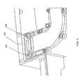
- FIGS. 4-7 a portion of a transceiver is shown with the cover removed exposing the transmit waveguide assembly inside (see FIG. 4 ).
- An example of the transmit waveguide/wall interface can be discussed with reference to FIG. 4 .
- the hardware (fasteners) 470 ( 570 in FIG. 5 ) can be parallel to the interface plane 490 .
- an attempt to install such fasteners in an orientation perpendicular to interface plane 490 could be difficult due to space limitations.
- it can be relatively simple to access and manipulate fasteners in an orientation parallel to interface plane 490 .
- a cut-a-way view of the cammed/wedge interface can be seen in FIG. 5 .
- the transmit waveguide steps down a few steps before the interface at the wall of the transceiver housing.
- the waveguide can have any suitable configuration, be it stepped, curved, straight, etc.
- the assembly of the waveguide portion and the chassis portion can be held together with fastener 670 .
- the waveguide piece can comprise a force transfer feature that can be rounded to create a cam motion at the interface.
- tightening the fasteners 670 can be configured so that a cam action pushes the mating faces together.
- the metal portions can be made of aluminum. The aluminum can allow minute flex of the waveguide parts, adding tension and stability to the interface, even during vibration input to the unit.
- an intentional interference can be designed into the size of the parts.
- the interference between the chassis force transfer feature 951 and the waveguide force transfer feature 952 when in the desired position, can be 0.002 inches. It is noted that FIG. 7 illustrates the mating surface between the chassis and waveguide as a straight line.
- any suitable method can be used for applying force to the angled surface in a direction orthogonal to the direction of compression in the interface, and thus providing the direct and uniform contact to minimize physical discontinuities at the interface.
- principles described herein can facilitate creating a low profile fitting assembly, wherein the fastener applies three in a direction orthogonal to a ‘waveguide’ to ‘chassis’ interface that nonetheless forces the two objects together.
- the method and device disclosed herein can facilitate forming a contact without fasteners engaging in a direction perpendicular to the interface. This can be useful where physical space constraints and costly machining techniques prevent using direct fasteners or electromagnetic chokes to achieve the low VSWR interface.
- the fasteners can be configured to not engage the second metal piece near the waveguide interface.
- the device and method disclosed herein can be used for various waveguide interfaces at any suitable frequency ranges, but can be particularly useful at microwave and millimeter-wave frequencies.
- a method of connecting a waveguide to a chassis can comprise the steps of: forming a waveguide with a force transference device; forming a chassis having a second force transference device, wherein the first and second force transference devices comprise complementary sloped surfaces; and applying an indirect compression force to the waveguide, wherein the indirect compression force can be translated through the complementary sloped surfaces to generate a compressive force that holds the waveguide and chassis together.
- the applying of an indirect compression force can be accomplished using a fastener.
- the fastener can be a bolt.
- the bolt can be, for example, partially threaded on the end for engaging the chassis.
Landscapes
- Engineering & Computer Science (AREA)
- Manufacturing & Machinery (AREA)
- Connection Of Plates (AREA)
Abstract
Description
Claims (22)
Priority Applications (1)
| Application Number | Priority Date | Filing Date | Title |
|---|---|---|---|
| US13/801,078 US9035728B2 (en) | 2012-09-14 | 2013-03-13 | Electromagnetic interface secured by using an indirect compression force to slidably engage first and second force transfer features |
Applications Claiming Priority (2)
| Application Number | Priority Date | Filing Date | Title |
|---|---|---|---|
| US201261701470P | 2012-09-14 | 2012-09-14 | |
| US13/801,078 US9035728B2 (en) | 2012-09-14 | 2013-03-13 | Electromagnetic interface secured by using an indirect compression force to slidably engage first and second force transfer features |
Publications (2)
| Publication Number | Publication Date |
|---|---|
| US20140077903A1 US20140077903A1 (en) | 2014-03-20 |
| US9035728B2 true US9035728B2 (en) | 2015-05-19 |
Family
ID=50273870
Family Applications (1)
| Application Number | Title | Priority Date | Filing Date |
|---|---|---|---|
| US13/801,078 Active 2033-07-21 US9035728B2 (en) | 2012-09-14 | 2013-03-13 | Electromagnetic interface secured by using an indirect compression force to slidably engage first and second force transfer features |
Country Status (1)
| Country | Link |
|---|---|
| US (1) | US9035728B2 (en) |
Cited By (1)
| Publication number | Priority date | Publication date | Assignee | Title |
|---|---|---|---|---|
| US10069465B2 (en) | 2016-04-21 | 2018-09-04 | Communications & Power Industries Llc | Amplifier control system |
Families Citing this family (1)
| Publication number | Priority date | Publication date | Assignee | Title |
|---|---|---|---|---|
| BR112019004003A2 (en) | 2016-09-06 | 2019-06-04 | Parker Hannifin Corp | polarizing set |
Citations (4)
| Publication number | Priority date | Publication date | Assignee | Title |
|---|---|---|---|---|
| US3390901A (en) * | 1967-02-27 | 1968-07-02 | Gen Electric | Quick disconnect flangeless waveguide coupling |
| US4011532A (en) * | 1976-01-14 | 1977-03-08 | The United States Of America As Represented By The Secretary Of The Air Force | Fast acting waveguide coupler |
| US20070252665A1 (en) * | 2006-05-01 | 2007-11-01 | Ems Technologies, Inc. | System for connecting waveguides |
| US20080303613A1 (en) * | 2007-06-07 | 2008-12-11 | Oml, Inc. | Waveguide interface for millimeter wave and sub-millimeter wave applications |
-
2013
- 2013-03-13 US US13/801,078 patent/US9035728B2/en active Active
Patent Citations (4)
| Publication number | Priority date | Publication date | Assignee | Title |
|---|---|---|---|---|
| US3390901A (en) * | 1967-02-27 | 1968-07-02 | Gen Electric | Quick disconnect flangeless waveguide coupling |
| US4011532A (en) * | 1976-01-14 | 1977-03-08 | The United States Of America As Represented By The Secretary Of The Air Force | Fast acting waveguide coupler |
| US20070252665A1 (en) * | 2006-05-01 | 2007-11-01 | Ems Technologies, Inc. | System for connecting waveguides |
| US20080303613A1 (en) * | 2007-06-07 | 2008-12-11 | Oml, Inc. | Waveguide interface for millimeter wave and sub-millimeter wave applications |
Cited By (1)
| Publication number | Priority date | Publication date | Assignee | Title |
|---|---|---|---|---|
| US10069465B2 (en) | 2016-04-21 | 2018-09-04 | Communications & Power Industries Llc | Amplifier control system |
Also Published As
| Publication number | Publication date |
|---|---|
| US20140077903A1 (en) | 2014-03-20 |
Similar Documents
| Publication | Publication Date | Title |
|---|---|---|
| US20120321379A1 (en) | Locking structure | |
| US9638554B2 (en) | Strain gauge holder | |
| EP2745963A1 (en) | Coupling for a cooling system in a cutting tool | |
| US9035728B2 (en) | Electromagnetic interface secured by using an indirect compression force to slidably engage first and second force transfer features | |
| JP5219750B2 (en) | Coaxial waveguide converter and radar equipment | |
| US9893398B2 (en) | Quick connect waveguide coupler using pertubations rotatably movable through slots between a locked position and an unlocked position | |
| US8196496B2 (en) | Screwdriver | |
| US10297962B1 (en) | Electrical connector for a power busbar | |
| US20120079715A1 (en) | Tweezer for detaching connector | |
| US20140339973A1 (en) | Slide assembly | |
| US8752234B2 (en) | Wiper connector | |
| US20220017021A1 (en) | Clamp assembly for mounting a mobile device | |
| US9318843B2 (en) | Rotatable RF connector with coupling nut | |
| US9046178B2 (en) | Self-retaining gasket and fastener retainer | |
| US9563238B2 (en) | Fixing member and electronic device | |
| US7567217B1 (en) | Antenna device | |
| US8167641B2 (en) | Connector and mounting assemblies including stress-distribution members | |
| US10859110B2 (en) | Holder of a fastener | |
| US10547163B2 (en) | Cable connector | |
| JP5366925B2 (en) | Jig for waveguide connection | |
| US9078369B2 (en) | Fastening device, casing using same, and fastening method | |
| CN202167592U (en) | Dielectric filter, radio frequency component and communication equipment | |
| US9689460B2 (en) | Diaper pin vibration damper | |
| CN107567223B (en) | Box structure suitable for quick assembly disassembly of internal part | |
| US20140284923A1 (en) | Pipe coupling |
Legal Events
| Date | Code | Title | Description |
|---|---|---|---|
| AS | Assignment |
Owner name: VIASAT, INC., CALIFORNIA Free format text: ASSIGNMENT OF ASSIGNORS INTEREST;ASSIGNORS:ZIENKEWICZ, ROB;POTEMRA, MIKE;REEL/FRAME:030188/0716 Effective date: 20130401 |
|
| AS | Assignment |
Owner name: UNION BANK, N.A., AS AGENT FOR THE SECURED PARTIES, CALIFORNIA Free format text: SECURITY AGREEMENT;ASSIGNOR:VIASAT, INC.;REEL/FRAME:031868/0789 Effective date: 20131126 Owner name: UNION BANK, N.A., AS AGENT FOR THE SECURED PARTIES Free format text: SECURITY AGREEMENT;ASSIGNOR:VIASAT, INC.;REEL/FRAME:031868/0789 Effective date: 20131126 |
|
| FEPP | Fee payment procedure |
Free format text: PAYOR NUMBER ASSIGNED (ORIGINAL EVENT CODE: ASPN); ENTITY STATUS OF PATENT OWNER: LARGE ENTITY |
|
| STCF | Information on status: patent grant |
Free format text: PATENTED CASE |
|
| CC | Certificate of correction | ||
| MAFP | Maintenance fee payment |
Free format text: PAYMENT OF MAINTENANCE FEE, 4TH YEAR, LARGE ENTITY (ORIGINAL EVENT CODE: M1551); ENTITY STATUS OF PATENT OWNER: LARGE ENTITY Year of fee payment: 4 |
|
| AS | Assignment |
Owner name: WILMINGTON TRUST, NATIONAL ASSOCIATION, AS COLLATE Free format text: SECURITY INTEREST;ASSIGNOR:VIASAT, INC.;REEL/FRAME:048715/0589 Effective date: 20190327 Owner name: WILMINGTON TRUST, NATIONAL ASSOCIATION, AS COLLATERAL TRUSTEE, MINNESOTA Free format text: SECURITY INTEREST;ASSIGNOR:VIASAT, INC.;REEL/FRAME:048715/0589 Effective date: 20190327 |
|
| AS | Assignment |
Owner name: BANK OF AMERICA, N.A., NORTH CAROLINA Free format text: SECURITY AGREEMENT;ASSIGNOR:VIASAT, INC.;REEL/FRAME:059332/0558 Effective date: 20220304 |
|
| MAFP | Maintenance fee payment |
Free format text: PAYMENT OF MAINTENANCE FEE, 8TH YEAR, LARGE ENTITY (ORIGINAL EVENT CODE: M1552); ENTITY STATUS OF PATENT OWNER: LARGE ENTITY Year of fee payment: 8 |
|
| AS | Assignment |
Owner name: BANK OF AMERICA, N.A., AS AGENT, NORTH CAROLINA Free format text: SECURITY AGREEMENT;ASSIGNOR:VIASAT, INC.;REEL/FRAME:063822/0446 Effective date: 20230530 |