EP3222442A1 - Pneumatic tire - Google Patents
Pneumatic tire Download PDFInfo
- Publication number
- EP3222442A1 EP3222442A1 EP15860259.9A EP15860259A EP3222442A1 EP 3222442 A1 EP3222442 A1 EP 3222442A1 EP 15860259 A EP15860259 A EP 15860259A EP 3222442 A1 EP3222442 A1 EP 3222442A1
- Authority
- EP
- European Patent Office
- Prior art keywords
- tire
- frame member
- surface recesses
- tire frame
- recesses
- Prior art date
- Legal status (The legal status is an assumption and is not a legal conclusion. Google has not performed a legal analysis and makes no representation as to the accuracy of the status listed.)
- Granted
Links
- 229920005989 resin Polymers 0.000 claims abstract description 32
- 239000011347 resin Substances 0.000 claims abstract description 32
- 239000011324 bead Substances 0.000 claims description 27
- 239000000463 material Substances 0.000 abstract description 16
- 229920001971 elastomer Polymers 0.000 description 15
- 229920005992 thermoplastic resin Polymers 0.000 description 13
- 229920002725 thermoplastic elastomer Polymers 0.000 description 10
- 239000005060 rubber Substances 0.000 description 9
- 238000000926 separation method Methods 0.000 description 9
- 239000000806 elastomer Substances 0.000 description 6
- 229920001169 thermoplastic Polymers 0.000 description 6
- 239000004416 thermosoftening plastic Substances 0.000 description 5
- 229910000831 Steel Inorganic materials 0.000 description 4
- 150000001875 compounds Chemical class 0.000 description 4
- 230000000694 effects Effects 0.000 description 4
- 229920006351 engineering plastic Polymers 0.000 description 4
- 229920000642 polymer Polymers 0.000 description 4
- 239000010959 steel Substances 0.000 description 4
- 238000001746 injection moulding Methods 0.000 description 3
- 238000004519 manufacturing process Methods 0.000 description 3
- 239000012815 thermoplastic material Substances 0.000 description 3
- 229920002397 thermoplastic olefin Polymers 0.000 description 3
- 229920006345 thermoplastic polyamide Polymers 0.000 description 3
- 239000004634 thermosetting polymer Substances 0.000 description 3
- 239000004793 Polystyrene Substances 0.000 description 2
- 239000004433 Thermoplastic polyurethane Substances 0.000 description 2
- 238000001816 cooling Methods 0.000 description 2
- 239000000835 fiber Substances 0.000 description 2
- 238000000465 moulding Methods 0.000 description 2
- 229920002223 polystyrene Polymers 0.000 description 2
- 230000003014 reinforcing effect Effects 0.000 description 2
- 229920002803 thermoplastic polyurethane Polymers 0.000 description 2
- 229920001187 thermosetting polymer Polymers 0.000 description 2
- 229920000877 Melamine resin Polymers 0.000 description 1
- 229920001807 Urea-formaldehyde Polymers 0.000 description 1
- BZHJMEDXRYGGRV-UHFFFAOYSA-N Vinyl chloride Chemical compound ClC=C BZHJMEDXRYGGRV-UHFFFAOYSA-N 0.000 description 1
- NIXOWILDQLNWCW-UHFFFAOYSA-N acrylic acid group Chemical group C(C=C)(=O)O NIXOWILDQLNWCW-UHFFFAOYSA-N 0.000 description 1
- 238000005266 casting Methods 0.000 description 1
- 230000006835 compression Effects 0.000 description 1
- 238000007906 compression Methods 0.000 description 1
- 230000008878 coupling Effects 0.000 description 1
- 238000010168 coupling process Methods 0.000 description 1
- 238000005859 coupling reaction Methods 0.000 description 1
- 229910003460 diamond Inorganic materials 0.000 description 1
- 239000010432 diamond Substances 0.000 description 1
- 239000003822 epoxy resin Substances 0.000 description 1
- 239000002657 fibrous material Substances 0.000 description 1
- -1 fluororesins Polymers 0.000 description 1
- LNEPOXFFQSENCJ-UHFFFAOYSA-N haloperidol Chemical compound C1CC(O)(C=2C=CC(Cl)=CC=2)CCN1CCCC(=O)C1=CC=C(F)C=C1 LNEPOXFFQSENCJ-UHFFFAOYSA-N 0.000 description 1
- 238000002347 injection Methods 0.000 description 1
- 239000007924 injection Substances 0.000 description 1
- 238000000034 method Methods 0.000 description 1
- 229920001568 phenolic resin Polymers 0.000 description 1
- 239000005011 phenolic resin Substances 0.000 description 1
- 229920000647 polyepoxide Polymers 0.000 description 1
- 229920000728 polyester Polymers 0.000 description 1
- 229920001225 polyester resin Polymers 0.000 description 1
- 239000002861 polymer material Substances 0.000 description 1
- 229920001296 polysiloxane Polymers 0.000 description 1
- 238000004064 recycling Methods 0.000 description 1
- 239000000243 solution Substances 0.000 description 1
- 239000004636 vulcanized rubber Substances 0.000 description 1
- 238000003466 welding Methods 0.000 description 1
Images



Classifications
-
- B—PERFORMING OPERATIONS; TRANSPORTING
- B60—VEHICLES IN GENERAL
- B60C—VEHICLE TYRES; TYRE INFLATION; TYRE CHANGING; CONNECTING VALVES TO INFLATABLE ELASTIC BODIES IN GENERAL; DEVICES OR ARRANGEMENTS RELATED TO TYRES
- B60C13/00—Tyre sidewalls; Protecting, decorating, marking, or the like, thereof
- B60C13/02—Arrangement of grooves or ribs
-
- B—PERFORMING OPERATIONS; TRANSPORTING
- B60—VEHICLES IN GENERAL
- B60C—VEHICLE TYRES; TYRE INFLATION; TYRE CHANGING; CONNECTING VALVES TO INFLATABLE ELASTIC BODIES IN GENERAL; DEVICES OR ARRANGEMENTS RELATED TO TYRES
- B60C9/00—Reinforcements or ply arrangement of pneumatic tyres
- B60C9/02—Carcasses
-
- B—PERFORMING OPERATIONS; TRANSPORTING
- B60—VEHICLES IN GENERAL
- B60C—VEHICLE TYRES; TYRE INFLATION; TYRE CHANGING; CONNECTING VALVES TO INFLATABLE ELASTIC BODIES IN GENERAL; DEVICES OR ARRANGEMENTS RELATED TO TYRES
- B60C13/00—Tyre sidewalls; Protecting, decorating, marking, or the like, thereof
-
- B—PERFORMING OPERATIONS; TRANSPORTING
- B60—VEHICLES IN GENERAL
- B60C—VEHICLE TYRES; TYRE INFLATION; TYRE CHANGING; CONNECTING VALVES TO INFLATABLE ELASTIC BODIES IN GENERAL; DEVICES OR ARRANGEMENTS RELATED TO TYRES
- B60C5/00—Inflatable pneumatic tyres or inner tubes
- B60C5/007—Inflatable pneumatic tyres or inner tubes made from other material than rubber
-
- B—PERFORMING OPERATIONS; TRANSPORTING
- B60—VEHICLES IN GENERAL
- B60C—VEHICLE TYRES; TYRE INFLATION; TYRE CHANGING; CONNECTING VALVES TO INFLATABLE ELASTIC BODIES IN GENERAL; DEVICES OR ARRANGEMENTS RELATED TO TYRES
- B60C5/00—Inflatable pneumatic tyres or inner tubes
- B60C5/01—Inflatable pneumatic tyres or inner tubes without substantial cord reinforcement, e.g. cordless tyres, cast tyres
Definitions
- the present invention relates to a pneumatic tire, and in particular relates to a pneumatic tire in which a tire frame member is formed using a resin material.
- thermoplastic polymer materials such as thermoplastic elastomers (TPE) or thermoplastic resins to configure tire frame members.
- TPE thermoplastic elastomers
- JP-A Japanese Patent Application Laid-Open
- H03-143701 describes forming a pneumatic tire by employing a tire frame member formed by covering bead cores with a thermoplastic elastomer.
- an object of the present invention is to lessen the load on a tire caused by tensile force acting on a tire outer surface.
- a pneumatic tire according to a first aspect of the present invention includes a tire frame member.
- the tire frame member is made from a resin, and includes a bead portion, a side portion that is continuous from a tire radial direction outer side of the bead portion, and a crown portion that is continuous from a tire width direction inner side of the side portion and on which a tread is disposed.
- the tire frame member is also formed with plural outer surface recesses on an outer surface of the side portion, the outer surface recesses being separated from each other in rows in the tire radial direction and in a tire circumferential direction.
- the plural outer surface recesses are separated from each other on the outer surface of the side portion.
- the outer surface recesses thereby facilitate deformation of the resin at the outer surfaces of the side portion. This relieves stress and strain caused by tensile force acting on the outer surface of the tire, thereby enabling the load on the tire frame member that is formed from a resin material to be lessened.
- the pneumatic tire according to the present invention is capable of lessening load caused by tensile force acting on the outer surface of the tire.
- the arrow W indicates a tire axial direction
- the arrow R indicates a tire radial direction extending from a tire axis (not illustrated in the drawings) in a radial direction of the tire
- the arrow C indicates a tire circumferential direction.
- a pneumatic tire of the present exemplary embodiment is a tire employed internally filled with air.
- a pneumatic tire 10 includes a circular tire frame member 17.
- the tire frame member 17 includes a pair of bead portions 12, side portions 14 extending from the respective bead portions 12 toward a tire radial direction outside, and a crown portion 16 coupling together both tire radial direction outside ends of the respective side portions 14.
- the bead portions refer to portions spanning from tire radial direction inside ends up to 30% of the cross-sectional height of the tire.
- the pair of bead portions 12 make close contact with bead seats 21 and rim flanges 22 of a rim 20 so as to maintain the internal pressure of the air-filled tire.
- separation points 36 boundary portions where the bead portions 12 come away from the rim 20 are referred to as separation points 36, these being points where the tire separates from the rim flanges when the tire is fitted to the specified rim according to the dimension of the tire as listed in the 2013 edition of the Japan Automobile Tire Manufacturers' Association (JATMA) YEAR BOOK, in an unloaded state at the internal pressure specified therein. Positions corresponding to the separation points 36 on an outer surface of the tire frame member 17 configure case separation points 38.
- a tread member 30 configuring a tire tread is disposed at the tire radial direction outside of the crown portion 16.
- the tire frame member 17 is made of a resin, and is formed from a resin material as the main material.
- resin material does not include vulcanized rubber.
- resin materials include thermoplastic resins (including thermoplastic elastomers), thermosetting resins, and other general-purpose resins, as well as engineering plastics (including super engineering plastics) and the like.
- Thermoplastic resins are polymer compounds of materials that soften and flow with increased temperature, and that adopt a relatively hard and strong state when cooled.
- thermoplastic elastomers these being polymer compounds that soften and flow with increasing temperature, that adopt a relatively hard and strong state on cooling, and that have a rubber-like elasticity
- non-elastomer thermoplastic resins these being polymer compounds that soften and flow with increasing temperature, that adopt a relatively hard and strong state on cooling, and do not have a rubber-like elasticity.
- thermoplastic resins include thermoplastic polyolefin-based elastomers (TPO), thermoplastic polystyrene-based elastomers (TPS), thermoplastic polyamide-based elastomers (TPA), thermoplastic polyurethane-based elastomers (TPU), thermoplastic polyester-based elastomers (TPC), and dynamically crosslinked-type thermoplastic elastomers (TPV), as well as thermoplastic polyolefin-based resins, thermoplastic polystyrene-based resins, thermoplastic polyamide-based resins, thermoplastic polyester-based resins, and the like.
- TPO thermoplastic polyolefin-based elastomers
- TPS thermoplastic polystyrene-based elastomers
- TPA thermoplastic polyamide-based elastomers
- TPU thermoplastic polyurethane-based elastomers
- TPC thermoplastic polyester-based elastomers
- TPV dynamically crosslinked-type thermoplastic elast
- thermoplastic resin material mentioned above has, for example, the characteristics of a deflection temperature under load (when loaded at 0.45 MPa) as defined by ISO 75-2 or ASTM D648 of 78°C or greater, a tensile yield strength as defined by JIS K7113 of 10 MPa or greater, and tensile elongation at break, likewise defined by JIS K7113, of 50% or greater.
- a thermoplastic resin material having a Vicat softening temperature, as defined by JIS K7206 (method A), of 130°C or greater, may be employed.
- thermoset resins are polymer compounds that cure to form a three-dimensional mesh structure with increasing temperature.
- thermoset resins include phenolic resins, epoxy resins, melamine resins, and urea resins.
- thermoplastic resins including thermoplastic elastomers
- thermoset resins thermoset resins
- general-purpose resins such as (meth)acrylic-based resins, EVA resins, vinyl chloride resins, fluororesins, and silicone-based resins may also be employed as the resin material.
- the tire frame member 17 is formed by aligning circular tire frame halves 17A, each integrally molded in the same shape and including a single bead portion 12, a single side portion 14, and a half-width crown portion 16, and bonding the tire frame halves 17A together at a tire equatorial plane CL portion.
- a thermoplastic welding resin material 19 is used when bonding at the tire equatorial plane CL portion. Note that there is no limitation to forming the tire frame member 17 by bonding together two members, and the tire frame member 17 may be formed by bonding together three or more members, or may be integrally molded with a pair of the bead portions 12, a pair of the side portions 14, and the crown portion 16.
- the side portion of the present specification refers to a portion spanning from the bead portion to a tread end.
- the "tread end” refers to the outermost ground contact portion in the tire width direction when the tire is fitted to a standard rim, as defined in the JATMA YEAR BOOK (2014 edition, Japan Automobile Tire Manufacturers Association standards ), inflated to an internal pressure of 100% air pressure (maximum air pressure) corresponding to the maximum load capacity (load shown in bold in the internal pressure-load capacity correspondence table) for the applicable JATMA YEAR BOOK size/ply rating, and loaded to the maximum load capacity.
- maximum air pressure 100% air pressure
- the tire frame halves 17A formed using a thermoplastic material may, for example, be molded by vacuum molding, pressure forming, injection molding, melt casting, or the like, enabling the manufacturing process to be greatly simplified and enabling molding time to be reduced in comparison to cases in which the tire frame halves 17A are molded (vulcanized) using rubber. Note that even in cases in which the tire frame member 17 is configured from a single thermoplastic material, a thermoplastic material may be employed that has different characteristics at each location of the tire frame member 17 (the side portions 14, the crown portion 16, the bead portions 12, and the like), similarly to in general rubber pneumatic tires hitherto.
- Annular shaped bead cores 15 are embedded in the bead portions 12 of the tire frame member 17.
- the bead cores 15 are configured from steel cords, similarly to in general pneumatic tires hitherto. Note that the bead cores 15 may be omitted if the rigidity of the bead portions 12 is secured and there are no issues with fitting to the rim 20.
- the bead cores 15 may be formed by cords configured by materials other than steel, such as organic fiber cords or resin-coated organic fiber cords.
- the bead cores 15 may be formed from a hard resin using injection molding or the like.
- a reinforcing layer 28 including steel cords 26 wound on in a spiral shape is embedded in the crown portion 16 of the tire frame member 17.
- the reinforcing layer 28 corresponds to a belt disposed at an outer circumferential surface of the carcass of rubber pneumatic tires hitherto.
- Covering layers 24 are formed on the outer surface of the tire frame member 17 from the bead portions 12 to the tread member 30. A bead portion 12 side end portion of each covering layer 24 is disposed so as to reach further to the tire inside than the close contact portion between the bead portion 12 and the rim 20. The covering layers 24 also fill outer surface recesses 40, described later. Note that the covering layers 24 may be formed from a resin or from rubber. Examples of resin materials include thermoplastic resins (including thermoplastic elastomers), thermosetting resins, and other general resins, as well as engineering plastics (including super engineering plastics).
- the tread member 30 is disposed at the tire radial direction outside of the tire frame member 17.
- the tread member 30 is disposed along the tire frame member 17, and configures a tire tread, this being a ground contact portion of the tire 10.
- the tread member 30 is formed from a rubber that has superior anti-wear characteristics to the thermoplastic resin used to form the tire frame member 17.
- the rubber employed in the tread member 30 may be the same type of rubber as that employed in rubber pneumatic tires hitherto. Note that the tread member 30 may also be configured by another type of thermoplastic resin that has superior anti-wear characteristics to the thermoplastic resin used to form the tire frame member 17.
- plural of the outer surface recesses 40 are formed in tire outer surfaces 17OUT of the tire frame member 17.
- the plural outer surface recesses 40 are formed over the entirety of regions spanning from the respective case separation points 38 corresponding to the separation points 36 of the bead portions 12 from the rim flanges 22, as far as positions of the outer surface 17OUT corresponding to tread ends 30A, these being the tire width direction W outside ends of the tread member 30.
- the outer surface recesses 40 are arranged in rows along the tire radial direction R and a tire circumferential U direction.
- the reason for not forming the outer surface recesses 40 further to the tire radial direction inside than the case separation points 38 is that there is hardly any deformation of the tire here, and thus there is little need to form the outer surface recesses 40.
- the reason for not forming the outer surface recesses 40 further to the tire axial direction inside (closer to the tire equatorial plane CL side) than the tread end 30A is that the tread member 30 is disposed here.
- the rigidity of the tire frame member 17 can be maintained by not forming the outer surface recesses 40 at portions that are comparatively less affected by load application (portions that do not deform readily).
- each of the outer surface recesses 40 is configured by a substantially hemispherical recess. Adjacent outer surface recesses 40 are formed spaced apart from each other. The outer surface recesses 40 are formed over the entire outer surfaces of the side portions 14 of the tire frame member 17, and are formed over part of the outer surfaces of the bead portions 12.
- the outer surface recesses 40 disposed at positions closest to each other are separated by a spacing S1. Note that the spacing S1 becomes longer the further the outer surface recesses 40 are disposed toward the tire radial direction outside.
- the outer surface recesses 40 are covered by the respective covering layers 24.
- Forming the outer surface recesses 40 in this manner relieves stress and strain caused by tensile force acting on the outer surface of the tire, thereby enabling the load on the tire frame member 17 that is formed from a resin material to be lessened.
- outer surface recesses 40 are substantially hemispherical in shape, they are non-anisotropic, and are capable of relieving stress and strain caused by tensile force in a well-balanced manner.
- the outer surface recesses 40 may also be configured so as to be non-anisotropic and capable of relieving stress and strain caused by tensile force in a well-balanced manner by being configured with spherical surface profiles configuring part of the surface of a sphere.
- outer surface recesses 40 may be formed over the entirety of the regions from the case separation points 38 to the tread ends 30A, or may be formed over part of these regions.
- the outer surface recesses 40 are preferably formed at least within 30% of the tread end 30A side in the regions from the case separation points 38 to the tread ends 30A. This is since positions that are close to the tread ends 30A act as boundaries of the ground contact portion during vehicle travel and are subjected to a large load.
- outer surface recesses 40 are preferably formed along the entire tire circumferential direction in order to give the tire outer surface 17OUT a uniform profile in the tire circumferential direction.
- a depth D1 (depth at the deepest part) of the outer surface recesses 40 is preferably 0.1 mm or greater. This is since there is little stress-relieving effect at less than 0.1 mm. Moreover, the depth D1 is preferably no more than 1/2 of an average thickness H of the side portions 14. This is since the strength of the tire frame member 17 becomes insufficient when in excess of 1/2 the average thickness of the side portions 14.
- an opening (opening width) diameter D of the outer surface recesses 40 is preferably from 0.1 mm to 10.0 mm. This is since there is little stress-relieving effect if the diameter D is below 0.1 mm, and the strength of the tire frame member 17 becomes insufficient if the diameter D is greater than 10.0 mm.
- the spacing S1 between adjacent outer surface recesses 40 is preferably from 0.1 mm to 10.0 mm. This is since at less than 0.1 mm, processing (manufacture) of the outer surface recesses 40 becomes difficult, while there is little stress-relieving effect when in excess of 10.0 mm.
- the outer surface recesses 40 may be formed by forming projections for the outer surface recesses 40 on a corresponding portion of a mold used in injection molding of the tire frame member 17.
- the outer surface recesses 40 may also be formed by processing after the tire frame member 17 has been injection molded.
- the pneumatic tire 10 of the present exemplary embodiment is formed with the outer surface recesses 40 on the tire outer surface of the tire frame member 17. This facilitates deformation of the resin at the outer surface of the tire frame member 17, thereby enabling stress and strain caused by tensile force acting on the outer surface of the tire frame member 17 to be relieved and enabling load to be lessened.
- outer surface recesses 40 are only formed to the outer surface of the tire frame member 17.
- inner surface recesses 42 may also be formed at an inner surface of the tire frame member 17.
- the inner surface recesses 42 are formed to the tire frame member 17 at positions that do not overlap with the outer surface recesses 40, namely at portions of the inner surface side where the outer surface recesses 40 are not formed in the thickness direction of the tire frame member 17.
- forming the inner surface recesses 42 facilitates deformation of the resin at the inner surface of the tire frame member 17, thereby enabling stress and strain caused by compression force acting on the inner surface to be relieved, and enabling load on the tire frame member 17 to be lessened further. Moreover, since the inner surface recesses 42 are formed at positions that do not overlap with the outer surface recesses 40, locations where the thickness of the tire frame member 17 becomes excessively thin are not formed, enabling a reduction in strength to be suppressed.
- outer surface recesses are substantially hemispherical in shape.
- outer surface recesses there is no requirement for the outer surface recesses to be substantially hemispherical in shape.
- configuration may be made with hexagonal outer surface recesses 44 having substantially hexagonal shapes.
- configuration may be made with diamond-shaped outer surface recesses 46 having diamond shapes.
Landscapes
- Engineering & Computer Science (AREA)
- Mechanical Engineering (AREA)
- Tires In General (AREA)
Abstract
Description
- The present invention relates to a pneumatic tire, and in particular relates to a pneumatic tire in which a tire frame member is formed using a resin material.
- Pneumatic tires formed from rubber, organic fiber materials, and steel members are known. Recently, from the perspectives of reducing weight and facilitating recycling, there has been demand for the use of thermoplastic polymer materials such as thermoplastic elastomers (TPE) or thermoplastic resins to configure tire frame members. For example, Japanese Patent Application Laid-Open (
JP-A) No. H03-143701 - In such tire frame members formed from resin materials, load is repeatedly input during vehicle travel, and in particular, tensile force acts on an outer surface of the tire. Relieving this tensile force improves the durability of the tire.
- In consideration of the above circumstances, an object of the present invention is to lessen the load on a tire caused by tensile force acting on a tire outer surface.
- A pneumatic tire according to a first aspect of the present invention includes a tire frame member. The tire frame member is made from a resin, and includes a bead portion, a side portion that is continuous from a tire radial direction outer side of the bead portion, and a crown portion that is continuous from a tire width direction inner side of the side portion and on which a tread is disposed. The tire frame member is also formed with plural outer surface recesses on an outer surface of the side portion, the outer surface recesses being separated from each other in rows in the tire radial direction and in a tire circumferential direction.
- According to the pneumatic tire of the first aspect, the plural outer surface recesses are separated from each other on the outer surface of the side portion. The outer surface recesses thereby facilitate deformation of the resin at the outer surfaces of the side portion. This relieves stress and strain caused by tensile force acting on the outer surface of the tire, thereby enabling the load on the tire frame member that is formed from a resin material to be lessened.
- As described above, the pneumatic tire according to the present invention is capable of lessening load caused by tensile force acting on the outer surface of the tire.
-
-
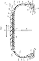
Fig. 1 is a cross-section illustrating a pneumatic tire according to an exemplary embodiment of the present invention. -
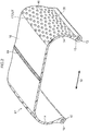
Fig. 2 is a partial perspective view illustrating a tire frame member of an exemplary embodiment of the present invention. -
Fig. 3 is a partial side view illustrating a tire frame member of an exemplary embodiment of the present invention. -
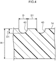
Fig. 4 is a cross-section taken along line A-A inFig. 3 . -
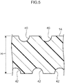
Fig. 5 is a partial cross-section illustrating a modified example of a tire frame member of an exemplary embodiment of the present invention. -
Fig. 6 is a partial side view illustrating a modified example of a tire frame member of an exemplary embodiment of the present invention. -
Fig. 7 is a partial side view illustrating another modified example of a tire frame member of an exemplary embodiment of the present invention. - In the following explanation, exemplary embodiments are used to explain implementation of the present invention. In the drawings, the arrow W indicates a tire axial direction, the arrow R indicates a tire radial direction extending from a tire axis (not illustrated in the drawings) in a radial direction of the tire, and the arrow C indicates a tire circumferential direction.
- As illustrated in
Fig. 1 , a pneumatic tire of the present exemplary embodiment is a tire employed internally filled with air. Apneumatic tire 10 includes a circulartire frame member 17. Thetire frame member 17 includes a pair ofbead portions 12,side portions 14 extending from therespective bead portions 12 toward a tire radial direction outside, and acrown portion 16 coupling together both tire radial direction outside ends of therespective side portions 14. Note that the bead portions refer to portions spanning from tire radial direction inside ends up to 30% of the cross-sectional height of the tire. The pair ofbead portions 12 make close contact withbead seats 21 andrim flanges 22 of arim 20 so as to maintain the internal pressure of the air-filled tire. Note that boundary portions where thebead portions 12 come away from therim 20 are referred to asseparation points 36, these being points where the tire separates from the rim flanges when the tire is fitted to the specified rim according to the dimension of the tire as listed in the 2013 edition of the Japan Automobile Tire Manufacturers' Association (JATMA) YEAR BOOK, in an unloaded state at the internal pressure specified therein. Positions corresponding to theseparation points 36 on an outer surface of thetire frame member 17 configurecase separation points 38. Atread member 30 configuring a tire tread, this being a portion where the tire contacts the ground, is disposed at the tire radial direction outside of thecrown portion 16. - The
tire frame member 17 is made of a resin, and is formed from a resin material as the main material. Note that here, "resin material" does not include vulcanized rubber. Examples of resin materials include thermoplastic resins (including thermoplastic elastomers), thermosetting resins, and other general-purpose resins, as well as engineering plastics (including super engineering plastics) and the like. - Thermoplastic resins (including thermoplastic elastomers) are polymer compounds of materials that soften and flow with increased temperature, and that adopt a relatively hard and strong state when cooled. In the present specification, out of these, distinction is made between thermoplastic elastomers, these being polymer compounds that soften and flow with increasing temperature, that adopt a relatively hard and strong state on cooling, and that have a rubber-like elasticity, and non-elastomer thermoplastic resins, these being polymer compounds that soften and flow with increasing temperature, that adopt a relatively hard and strong state on cooling, and do not have a rubber-like elasticity.
- Examples of thermoplastic resins (including thermoplastic elastomers) include thermoplastic polyolefin-based elastomers (TPO), thermoplastic polystyrene-based elastomers (TPS), thermoplastic polyamide-based elastomers (TPA), thermoplastic polyurethane-based elastomers (TPU), thermoplastic polyester-based elastomers (TPC), and dynamically crosslinked-type thermoplastic elastomers (TPV), as well as thermoplastic polyolefin-based resins, thermoplastic polystyrene-based resins, thermoplastic polyamide-based resins, thermoplastic polyester-based resins, and the like.
- Moreover, the thermoplastic resin material mentioned above has, for example, the characteristics of a deflection temperature under load (when loaded at 0.45 MPa) as defined by ISO 75-2 or ASTM D648 of 78°C or greater, a tensile yield strength as defined by JIS K7113 of 10 MPa or greater, and tensile elongation at break, likewise defined by JIS K7113, of 50% or greater. A thermoplastic resin material having a Vicat softening temperature, as defined by JIS K7206 (method A), of 130°C or greater, may be employed.
- Thermoset resins are polymer compounds that cure to form a three-dimensional mesh structure with increasing temperature. Examples of thermoset resins include phenolic resins, epoxy resins, melamine resins, and urea resins.
- In addition to the thermoplastic resins (including thermoplastic elastomers) and thermoset resins already listed above, general-purpose resins such as (meth)acrylic-based resins, EVA resins, vinyl chloride resins, fluororesins, and silicone-based resins may also be employed as the resin material.
- In the present exemplary embodiment, explanation is given regarding a case in which the
tire frame member 17 is formed from a thermoplastic resin. - The
tire frame member 17 is formed by aligning circulartire frame halves 17A, each integrally molded in the same shape and including asingle bead portion 12, asingle side portion 14, and a half-width crown portion 16, and bonding thetire frame halves 17A together at a tire equatorial plane CL portion. A thermoplasticwelding resin material 19 is used when bonding at the tire equatorial plane CL portion. Note that there is no limitation to forming thetire frame member 17 by bonding together two members, and thetire frame member 17 may be formed by bonding together three or more members, or may be integrally molded with a pair of thebead portions 12, a pair of theside portions 14, and thecrown portion 16. - Note that the side portion of the present specification refers to a portion spanning from the bead portion to a tread end. The "tread end" refers to the outermost ground contact portion in the tire width direction when the tire is fitted to a standard rim, as defined in the JATMA YEAR BOOK (2014 edition, Japan Automobile Tire Manufacturers Association standards), inflated to an internal pressure of 100% air pressure (maximum air pressure) corresponding to the maximum load capacity (load shown in bold in the internal pressure-load capacity correspondence table) for the applicable JATMA YEAR BOOK size/ply rating, and loaded to the maximum load capacity. In cases in which the location of use or manufacturing location falls under TRA standards or ETRTO standards, then the respective standards are adhered to.
- The
tire frame halves 17A formed using a thermoplastic material may, for example, be molded by vacuum molding, pressure forming, injection molding, melt casting, or the like, enabling the manufacturing process to be greatly simplified and enabling molding time to be reduced in comparison to cases in which thetire frame halves 17A are molded (vulcanized) using rubber. Note that even in cases in which thetire frame member 17 is configured from a single thermoplastic material, a thermoplastic material may be employed that has different characteristics at each location of the tire frame member 17 (theside portions 14, thecrown portion 16, thebead portions 12, and the like), similarly to in general rubber pneumatic tires hitherto. - Annular
shaped bead cores 15 are embedded in thebead portions 12 of thetire frame member 17. Thebead cores 15 are configured from steel cords, similarly to in general pneumatic tires hitherto. Note that thebead cores 15 may be omitted if the rigidity of thebead portions 12 is secured and there are no issues with fitting to therim 20. Moreover, thebead cores 15 may be formed by cords configured by materials other than steel, such as organic fiber cords or resin-coated organic fiber cords. Moreover, instead of using cords, thebead cores 15 may be formed from a hard resin using injection molding or the like. - A reinforcing
layer 28 includingsteel cords 26 wound on in a spiral shape is embedded in thecrown portion 16 of thetire frame member 17. The reinforcinglayer 28 corresponds to a belt disposed at an outer circumferential surface of the carcass of rubber pneumatic tires hitherto. - Covering layers 24 are formed on the outer surface of the
tire frame member 17 from thebead portions 12 to thetread member 30. Abead portion 12 side end portion of each coveringlayer 24 is disposed so as to reach further to the tire inside than the close contact portion between thebead portion 12 and therim 20. The covering layers 24 also fill outer surface recesses 40, described later. Note that the covering layers 24 may be formed from a resin or from rubber. Examples of resin materials include thermoplastic resins (including thermoplastic elastomers), thermosetting resins, and other general resins, as well as engineering plastics (including super engineering plastics). - The
tread member 30 is disposed at the tire radial direction outside of thetire frame member 17. Thetread member 30 is disposed along thetire frame member 17, and configures a tire tread, this being a ground contact portion of thetire 10. Thetread member 30 is formed from a rubber that has superior anti-wear characteristics to the thermoplastic resin used to form thetire frame member 17. The rubber employed in thetread member 30 may be the same type of rubber as that employed in rubber pneumatic tires hitherto. Note that thetread member 30 may also be configured by another type of thermoplastic resin that has superior anti-wear characteristics to the thermoplastic resin used to form thetire frame member 17. - As illustrated in
Fig. 2 , plural of the outer surface recesses 40 are formed in tire outer surfaces 17OUT of thetire frame member 17. The plural outer surface recesses 40 are formed over the entirety of regions spanning from the respective case separation points 38 corresponding to the separation points 36 of thebead portions 12 from therim flanges 22, as far as positions of the outer surface 17OUT corresponding to tread ends 30A, these being the tire width direction W outside ends of thetread member 30. The outer surface recesses 40 are arranged in rows along the tire radial direction R and a tire circumferential U direction. The reason for not forming the outer surface recesses 40 further to the tire radial direction inside than the case separation points 38 is that there is hardly any deformation of the tire here, and thus there is little need to form the outer surface recesses 40. Moreover, the reason for not forming the outer surface recesses 40 further to the tire axial direction inside (closer to the tire equatorial plane CL side) than thetread end 30A is that thetread member 30 is disposed here. The rigidity of thetire frame member 17 can be maintained by not forming the outer surface recesses 40 at portions that are comparatively less affected by load application (portions that do not deform readily). - As illustrated in
Fig. 3 andFig. 4 , each of the outer surface recesses 40 is configured by a substantially hemispherical recess. Adjacent outer surface recesses 40 are formed spaced apart from each other. The outer surface recesses 40 are formed over the entire outer surfaces of theside portions 14 of thetire frame member 17, and are formed over part of the outer surfaces of thebead portions 12. - As illustrated in
Fig. 4 , out of adjacent outer surface recesses 40, the outer surface recesses 40 disposed at positions closest to each other are separated by a spacing S1. Note that the spacing S1 becomes longer the further the outer surface recesses 40 are disposed toward the tire radial direction outside. The outer surface recesses 40 are covered by the respective covering layers 24. - Forming the outer surface recesses 40 in this manner relieves stress and strain caused by tensile force acting on the outer surface of the tire, thereby enabling the load on the
tire frame member 17 that is formed from a resin material to be lessened. - Moreover, even should cracks occur on the outer surface of the
side portions 14, development of the cracks can be suppressed due to disposing the outer surface recesses 40 at a separation from one another. - Moreover, since the outer surface recesses 40 are substantially hemispherical in shape, they are non-anisotropic, and are capable of relieving stress and strain caused by tensile force in a well-balanced manner. Note that the outer surface recesses 40 may also be configured so as to be non-anisotropic and capable of relieving stress and strain caused by tensile force in a well-balanced manner by being configured with spherical surface profiles configuring part of the surface of a sphere.
- Note that the outer surface recesses 40 may be formed over the entirety of the regions from the case separation points 38 to the tread ends 30A, or may be formed over part of these regions. The outer surface recesses 40 are preferably formed at least within 30% of the tread end 30A side in the regions from the case separation points 38 to the tread ends 30A. This is since positions that are close to the tread ends 30A act as boundaries of the ground contact portion during vehicle travel and are subjected to a large load.
- Moreover, the outer surface recesses 40 are preferably formed along the entire tire circumferential direction in order to give the tire outer surface 17OUT a uniform profile in the tire circumferential direction.
- Moreover, a depth D1 (depth at the deepest part) of the outer surface recesses 40 is preferably 0.1 mm or greater. This is since there is little stress-relieving effect at less than 0.1 mm. Moreover, the depth D1 is preferably no more than 1/2 of an average thickness H of the
side portions 14. This is since the strength of thetire frame member 17 becomes insufficient when in excess of 1/2 the average thickness of theside portions 14. - Moreover, an opening (opening width) diameter D of the outer surface recesses 40 is preferably from 0.1 mm to 10.0 mm. This is since there is little stress-relieving effect if the diameter D is below 0.1 mm, and the strength of the
tire frame member 17 becomes insufficient if the diameter D is greater than 10.0 mm. - Moreover, the spacing S1 between adjacent outer surface recesses 40 is preferably from 0.1 mm to 10.0 mm. This is since at less than 0.1 mm, processing (manufacture) of the outer surface recesses 40 becomes difficult, while there is little stress-relieving effect when in excess of 10.0 mm.
- The outer surface recesses 40 may be formed by forming projections for the outer surface recesses 40 on a corresponding portion of a mold used in injection molding of the
tire frame member 17. The outer surface recesses 40 may also be formed by processing after thetire frame member 17 has been injection molded. - As described above, the
pneumatic tire 10 of the present exemplary embodiment is formed with the outer surface recesses 40 on the tire outer surface of thetire frame member 17. This facilitates deformation of the resin at the outer surface of thetire frame member 17, thereby enabling stress and strain caused by tensile force acting on the outer surface of thetire frame member 17 to be relieved and enabling load to be lessened. - Note that in the present exemplary embodiment the outer surface recesses 40 are only formed to the outer surface of the
tire frame member 17. However, inner surface recesses 42 may also be formed at an inner surface of thetire frame member 17. In such cases, as illustrated inFig. 5 , the inner surface recesses 42 are formed to thetire frame member 17 at positions that do not overlap with the outer surface recesses 40, namely at portions of the inner surface side where the outer surface recesses 40 are not formed in the thickness direction of thetire frame member 17. - In this manner, forming the inner surface recesses 42 facilitates deformation of the resin at the inner surface of the
tire frame member 17, thereby enabling stress and strain caused by compression force acting on the inner surface to be relieved, and enabling load on thetire frame member 17 to be lessened further. Moreover, since the inner surface recesses 42 are formed at positions that do not overlap with the outer surface recesses 40, locations where the thickness of thetire frame member 17 becomes excessively thin are not formed, enabling a reduction in strength to be suppressed. - In the present exemplary embodiment, explanation has been given regarding an example in which the outer surface recesses are substantially hemispherical in shape. However, there is no requirement for the outer surface recesses to be substantially hemispherical in shape. For example, as illustrated in
Fig. 6 , configuration may be made with hexagonal outer surface recesses 44 having substantially hexagonal shapes. Moreover, as illustrated inFig. 7 , configuration may be made with diamond-shaped outer surface recesses 46 having diamond shapes. - The disclosure of Japanese Patent Application No.
2014-234890 - All cited documents, patent applications, and technical standards mentioned in the present specification are incorporated by reference in the present specification to the same extent as if the individual cited document, patent application, or technical standard was specifically and individually indicated to be incorporated by reference.
Claims (6)
- A pneumatic tire, comprising a tire frame member, wherein the tire frame member:is made from a resin;includes a bead portion, a side portion that is continuous from a tire radial direction outer side of the bead portion, and a crown portion that is continuous from a tire width direction inner side of the side portion and on which a tread is disposed; andis formed with a plurality of outer surface recesses on an outer surface of the side portion, the outer surface recesses being separated from each other in rows in the tire radial direction and in a tire circumferential direction.
- The pneumatic tire of claim 1, wherein a plurality of inner surface recesses are formed on an inner surface of the side portion, so as to be separated from each other, at positions that do not overlap with the outer surface recesses.
- The pneumatic tire of either claim 1 or claim 2, wherein the outer surface recesses have a spherical surface profile.
- The pneumatic tire of any one of claim 1 to claim 3, wherein the outer surface recesses have a depth that is 0.1 mm or greater but not more than one-half of a thickness of the side portion.
- The pneumatic tire of any one of claim 1 to claim 4, wherein each of the outer surface recesses has a maximum opening width of from 0.1 mm to 10.0 mm.
- The pneumatic tire of any one of claim 1 to claim 5, wherein a minimum distance between adjacent outer surface recesses is from 0.1 mm to 10.0 mm.
Applications Claiming Priority (2)
| Application Number | Priority Date | Filing Date | Title |
|---|---|---|---|
| JP2014234890A JP6434284B2 (en) | 2014-11-19 | 2014-11-19 | Pneumatic tire |
| PCT/JP2015/078386 WO2016080099A1 (en) | 2014-11-19 | 2015-10-06 | Pneumatic tire |
Publications (3)
| Publication Number | Publication Date |
|---|---|
| EP3222442A1 true EP3222442A1 (en) | 2017-09-27 |
| EP3222442A4 EP3222442A4 (en) | 2017-11-29 |
| EP3222442B1 EP3222442B1 (en) | 2018-12-12 |
Family
ID=56013657
Family Applications (1)
| Application Number | Title | Priority Date | Filing Date |
|---|---|---|---|
| EP15860259.9A Not-in-force EP3222442B1 (en) | 2014-11-19 | 2015-10-06 | Pneumatic tire |
Country Status (5)
| Country | Link |
|---|---|
| US (1) | US20190092099A1 (en) |
| EP (1) | EP3222442B1 (en) |
| JP (1) | JP6434284B2 (en) |
| CN (1) | CN107107681B (en) |
| WO (1) | WO2016080099A1 (en) |
Families Citing this family (2)
| Publication number | Priority date | Publication date | Assignee | Title |
|---|---|---|---|---|
| JP7136746B2 (en) * | 2019-06-11 | 2022-09-13 | 株式会社ブリヂストン | tire |
| US20230202236A1 (en) * | 2020-05-29 | 2023-06-29 | Sumitomo Rubber Industries, Ltd. | Tire |
Family Cites Families (20)
| Publication number | Priority date | Publication date | Assignee | Title |
|---|---|---|---|---|
| IT1003055B (en) * | 1972-03-28 | 1976-06-10 | Pirelli | TIRE FOR VEHICLE WHEELS |
| DE2263370C3 (en) * | 1972-12-23 | 1982-01-21 | Continental Gummi-Werke Ag, 3000 Hannover | Pneumatic vehicle tires with undulating side walls |
| US4936365A (en) * | 1988-12-12 | 1990-06-26 | The Goodyear Tire & Rubber Company | Anisotropic tire |
| JPH03143701A (en) * | 1989-10-27 | 1991-06-19 | Sumitomo Rubber Ind Ltd | Pneumatic tire |
| JP2000016030A (en) * | 1998-07-07 | 2000-01-18 | Yokohama Rubber Co Ltd:The | Pneumatic radial tire |
| US20040131787A1 (en) * | 2002-11-26 | 2004-07-08 | Pennzoil-Quaker State Company | Aqueous based tire dressing compositions and methods of making |
| JP4655694B2 (en) * | 2005-03-09 | 2011-03-23 | 横浜ゴム株式会社 | Pneumatic tire |
| JP2008001249A (en) * | 2006-06-23 | 2008-01-10 | Yokohama Rubber Co Ltd:The | Pneumatic tire |
| JP4801702B2 (en) * | 2008-07-31 | 2011-10-26 | 住友ゴム工業株式会社 | Pneumatic tire |
| JP2010188635A (en) * | 2009-02-18 | 2010-09-02 | Bridgestone Corp | Mold and method for manufacturing tire |
| JP5418767B2 (en) * | 2009-04-30 | 2014-02-19 | 横浜ゴム株式会社 | Pneumatic tire |
| BRPI1011635A2 (en) * | 2009-06-01 | 2016-03-22 | Sumitomo Rubber Ind | tire |
| JP5436303B2 (en) * | 2010-03-30 | 2014-03-05 | 株式会社ブリヂストン | Tire and tire manufacturing method |
| CN102463848B (en) * | 2010-10-29 | 2015-05-06 | 横滨橡胶株式会社 | Pneumatic tire |
| JP5467081B2 (en) * | 2011-08-10 | 2014-04-09 | 住友ゴム工業株式会社 | Pneumatic tire |
| JP2013071680A (en) * | 2011-09-28 | 2013-04-22 | Yokohama Rubber Co Ltd:The | Pneumatic tire unit |
| JP5929437B2 (en) * | 2012-04-04 | 2016-06-08 | 横浜ゴム株式会社 | Pneumatic tire |
| JP5868303B2 (en) * | 2012-10-16 | 2016-02-24 | 横浜ゴム株式会社 | Pneumatic tire |
| JP2014168997A (en) * | 2013-03-01 | 2014-09-18 | Bridgestone Corp | tire |
| JP6284930B2 (en) * | 2013-04-22 | 2018-02-28 | 株式会社ブリヂストン | tire |
-
2014
- 2014-11-19 JP JP2014234890A patent/JP6434284B2/en not_active Expired - Fee Related
-
2015
- 2015-10-06 CN CN201580061331.9A patent/CN107107681B/en not_active Expired - Fee Related
- 2015-10-06 US US15/527,078 patent/US20190092099A1/en not_active Abandoned
- 2015-10-06 EP EP15860259.9A patent/EP3222442B1/en not_active Not-in-force
- 2015-10-06 WO PCT/JP2015/078386 patent/WO2016080099A1/en not_active Ceased
Also Published As
| Publication number | Publication date |
|---|---|
| JP6434284B2 (en) | 2018-12-05 |
| EP3222442B1 (en) | 2018-12-12 |
| CN107107681A (en) | 2017-08-29 |
| US20190092099A1 (en) | 2019-03-28 |
| JP2016097749A (en) | 2016-05-30 |
| CN107107681B (en) | 2020-02-14 |
| EP3222442A4 (en) | 2017-11-29 |
| WO2016080099A1 (en) | 2016-05-26 |
Similar Documents
| Publication | Publication Date | Title |
|---|---|---|
| EP3176003B1 (en) | Tire | |
| EP2990219B1 (en) | Tire | |
| US20180354303A1 (en) | Tire | |
| EP2960077B1 (en) | Tire | |
| EP3290229B1 (en) | Tire | |
| US20180290494A1 (en) | Tire | |
| EP3020571A1 (en) | Tire | |
| US10493807B2 (en) | Pneumatic tire | |
| EP3222442B1 (en) | Pneumatic tire | |
| US20200122509A1 (en) | Pneumatic tire | |
| EP3192646B1 (en) | Method for manufacturing tire, and tire | |
| EP3020569B1 (en) | Pneumatic tire | |
| EP3805014B1 (en) | Tire | |
| WO2019230353A1 (en) | Tire | |
| EP3808574A1 (en) | Pneumatic tire |
Legal Events
| Date | Code | Title | Description |
|---|---|---|---|
| STAA | Information on the status of an ep patent application or granted ep patent |
Free format text: STATUS: THE INTERNATIONAL PUBLICATION HAS BEEN MADE |
|
| PUAI | Public reference made under article 153(3) epc to a published international application that has entered the european phase |
Free format text: ORIGINAL CODE: 0009012 |
|
| STAA | Information on the status of an ep patent application or granted ep patent |
Free format text: STATUS: REQUEST FOR EXAMINATION WAS MADE |
|
| 17P | Request for examination filed |
Effective date: 20170602 |
|
| AK | Designated contracting states |
Kind code of ref document: A1 Designated state(s): AL AT BE BG CH CY CZ DE DK EE ES FI FR GB GR HR HU IE IS IT LI LT LU LV MC MK MT NL NO PL PT RO RS SE SI SK SM TR |
|
| AX | Request for extension of the european patent |
Extension state: BA ME |
|
| A4 | Supplementary search report drawn up and despatched |
Effective date: 20171026 |
|
| RIC1 | Information provided on ipc code assigned before grant |
Ipc: B60C 5/01 20060101ALI20171020BHEP Ipc: B60C 13/02 20060101ALI20171020BHEP Ipc: B60C 13/00 20060101AFI20171020BHEP Ipc: B60C 5/00 20060101ALI20171020BHEP |
|
| DAV | Request for validation of the european patent (deleted) | ||
| DAX | Request for extension of the european patent (deleted) | ||
| GRAP | Despatch of communication of intention to grant a patent |
Free format text: ORIGINAL CODE: EPIDOSNIGR1 |
|
| STAA | Information on the status of an ep patent application or granted ep patent |
Free format text: STATUS: GRANT OF PATENT IS INTENDED |
|
| RIC1 | Information provided on ipc code assigned before grant |
Ipc: B60C 13/00 20060101AFI20180606BHEP Ipc: B60C 5/00 20060101ALI20180606BHEP Ipc: B60C 5/01 20060101ALI20180606BHEP Ipc: B60C 13/02 20060101ALI20180606BHEP |
|
| INTG | Intention to grant announced |
Effective date: 20180628 |
|
| GRAS | Grant fee paid |
Free format text: ORIGINAL CODE: EPIDOSNIGR3 |
|
| GRAA | (expected) grant |
Free format text: ORIGINAL CODE: 0009210 |
|
| STAA | Information on the status of an ep patent application or granted ep patent |
Free format text: STATUS: THE PATENT HAS BEEN GRANTED |
|
| AK | Designated contracting states |
Kind code of ref document: B1 Designated state(s): AL AT BE BG CH CY CZ DE DK EE ES FI FR GB GR HR HU IE IS IT LI LT LU LV MC MK MT NL NO PL PT RO RS SE SI SK SM TR |
|
| REG | Reference to a national code |
Ref country code: GB Ref legal event code: FG4D |
|
| REG | Reference to a national code |
Ref country code: CH Ref legal event code: EP |
|
| REG | Reference to a national code |
Ref country code: AT Ref legal event code: REF Ref document number: 1075453 Country of ref document: AT Kind code of ref document: T Effective date: 20181215 |
|
| REG | Reference to a national code |
Ref country code: DE Ref legal event code: R096 Ref document number: 602015021701 Country of ref document: DE |
|
| REG | Reference to a national code |
Ref country code: IE Ref legal event code: FG4D |
|
| REG | Reference to a national code |
Ref country code: NL Ref legal event code: MP Effective date: 20181212 |
|
| REG | Reference to a national code |
Ref country code: LT Ref legal event code: MG4D |
|
| PG25 | Lapsed in a contracting state [announced via postgrant information from national office to epo] |
Ref country code: LV Free format text: LAPSE BECAUSE OF FAILURE TO SUBMIT A TRANSLATION OF THE DESCRIPTION OR TO PAY THE FEE WITHIN THE PRESCRIBED TIME-LIMIT Effective date: 20181212 Ref country code: LT Free format text: LAPSE BECAUSE OF FAILURE TO SUBMIT A TRANSLATION OF THE DESCRIPTION OR TO PAY THE FEE WITHIN THE PRESCRIBED TIME-LIMIT Effective date: 20181212 Ref country code: HR Free format text: LAPSE BECAUSE OF FAILURE TO SUBMIT A TRANSLATION OF THE DESCRIPTION OR TO PAY THE FEE WITHIN THE PRESCRIBED TIME-LIMIT Effective date: 20181212 Ref country code: BG Free format text: LAPSE BECAUSE OF FAILURE TO SUBMIT A TRANSLATION OF THE DESCRIPTION OR TO PAY THE FEE WITHIN THE PRESCRIBED TIME-LIMIT Effective date: 20190312 Ref country code: FI Free format text: LAPSE BECAUSE OF FAILURE TO SUBMIT A TRANSLATION OF THE DESCRIPTION OR TO PAY THE FEE WITHIN THE PRESCRIBED TIME-LIMIT Effective date: 20181212 Ref country code: NO Free format text: LAPSE BECAUSE OF FAILURE TO SUBMIT A TRANSLATION OF THE DESCRIPTION OR TO PAY THE FEE WITHIN THE PRESCRIBED TIME-LIMIT Effective date: 20190312 |
|
| REG | Reference to a national code |
Ref country code: AT Ref legal event code: MK05 Ref document number: 1075453 Country of ref document: AT Kind code of ref document: T Effective date: 20181212 |
|
| PG25 | Lapsed in a contracting state [announced via postgrant information from national office to epo] |
Ref country code: GR Free format text: LAPSE BECAUSE OF FAILURE TO SUBMIT A TRANSLATION OF THE DESCRIPTION OR TO PAY THE FEE WITHIN THE PRESCRIBED TIME-LIMIT Effective date: 20190313 Ref country code: SE Free format text: LAPSE BECAUSE OF FAILURE TO SUBMIT A TRANSLATION OF THE DESCRIPTION OR TO PAY THE FEE WITHIN THE PRESCRIBED TIME-LIMIT Effective date: 20181212 Ref country code: RS Free format text: LAPSE BECAUSE OF FAILURE TO SUBMIT A TRANSLATION OF THE DESCRIPTION OR TO PAY THE FEE WITHIN THE PRESCRIBED TIME-LIMIT Effective date: 20181212 Ref country code: AL Free format text: LAPSE BECAUSE OF FAILURE TO SUBMIT A TRANSLATION OF THE DESCRIPTION OR TO PAY THE FEE WITHIN THE PRESCRIBED TIME-LIMIT Effective date: 20181212 |
|
| PG25 | Lapsed in a contracting state [announced via postgrant information from national office to epo] |
Ref country code: NL Free format text: LAPSE BECAUSE OF FAILURE TO SUBMIT A TRANSLATION OF THE DESCRIPTION OR TO PAY THE FEE WITHIN THE PRESCRIBED TIME-LIMIT Effective date: 20181212 |
|
| PG25 | Lapsed in a contracting state [announced via postgrant information from national office to epo] |
Ref country code: IT Free format text: LAPSE BECAUSE OF FAILURE TO SUBMIT A TRANSLATION OF THE DESCRIPTION OR TO PAY THE FEE WITHIN THE PRESCRIBED TIME-LIMIT Effective date: 20181212 Ref country code: PT Free format text: LAPSE BECAUSE OF FAILURE TO SUBMIT A TRANSLATION OF THE DESCRIPTION OR TO PAY THE FEE WITHIN THE PRESCRIBED TIME-LIMIT Effective date: 20190412 Ref country code: CZ Free format text: LAPSE BECAUSE OF FAILURE TO SUBMIT A TRANSLATION OF THE DESCRIPTION OR TO PAY THE FEE WITHIN THE PRESCRIBED TIME-LIMIT Effective date: 20181212 Ref country code: ES Free format text: LAPSE BECAUSE OF FAILURE TO SUBMIT A TRANSLATION OF THE DESCRIPTION OR TO PAY THE FEE WITHIN THE PRESCRIBED TIME-LIMIT Effective date: 20181212 Ref country code: PL Free format text: LAPSE BECAUSE OF FAILURE TO SUBMIT A TRANSLATION OF THE DESCRIPTION OR TO PAY THE FEE WITHIN THE PRESCRIBED TIME-LIMIT Effective date: 20181212 |
|
| PG25 | Lapsed in a contracting state [announced via postgrant information from national office to epo] |
Ref country code: SK Free format text: LAPSE BECAUSE OF FAILURE TO SUBMIT A TRANSLATION OF THE DESCRIPTION OR TO PAY THE FEE WITHIN THE PRESCRIBED TIME-LIMIT Effective date: 20181212 Ref country code: RO Free format text: LAPSE BECAUSE OF FAILURE TO SUBMIT A TRANSLATION OF THE DESCRIPTION OR TO PAY THE FEE WITHIN THE PRESCRIBED TIME-LIMIT Effective date: 20181212 Ref country code: IS Free format text: LAPSE BECAUSE OF FAILURE TO SUBMIT A TRANSLATION OF THE DESCRIPTION OR TO PAY THE FEE WITHIN THE PRESCRIBED TIME-LIMIT Effective date: 20190412 Ref country code: EE Free format text: LAPSE BECAUSE OF FAILURE TO SUBMIT A TRANSLATION OF THE DESCRIPTION OR TO PAY THE FEE WITHIN THE PRESCRIBED TIME-LIMIT Effective date: 20181212 Ref country code: SM Free format text: LAPSE BECAUSE OF FAILURE TO SUBMIT A TRANSLATION OF THE DESCRIPTION OR TO PAY THE FEE WITHIN THE PRESCRIBED TIME-LIMIT Effective date: 20181212 |
|
| REG | Reference to a national code |
Ref country code: DE Ref legal event code: R097 Ref document number: 602015021701 Country of ref document: DE |
|
| PLBE | No opposition filed within time limit |
Free format text: ORIGINAL CODE: 0009261 |
|
| STAA | Information on the status of an ep patent application or granted ep patent |
Free format text: STATUS: NO OPPOSITION FILED WITHIN TIME LIMIT |
|
| PG25 | Lapsed in a contracting state [announced via postgrant information from national office to epo] |
Ref country code: SI Free format text: LAPSE BECAUSE OF FAILURE TO SUBMIT A TRANSLATION OF THE DESCRIPTION OR TO PAY THE FEE WITHIN THE PRESCRIBED TIME-LIMIT Effective date: 20181212 Ref country code: DK Free format text: LAPSE BECAUSE OF FAILURE TO SUBMIT A TRANSLATION OF THE DESCRIPTION OR TO PAY THE FEE WITHIN THE PRESCRIBED TIME-LIMIT Effective date: 20181212 Ref country code: AT Free format text: LAPSE BECAUSE OF FAILURE TO SUBMIT A TRANSLATION OF THE DESCRIPTION OR TO PAY THE FEE WITHIN THE PRESCRIBED TIME-LIMIT Effective date: 20181212 |
|
| 26N | No opposition filed |
Effective date: 20190913 |
|
| PG25 | Lapsed in a contracting state [announced via postgrant information from national office to epo] |
Ref country code: TR Free format text: LAPSE BECAUSE OF FAILURE TO SUBMIT A TRANSLATION OF THE DESCRIPTION OR TO PAY THE FEE WITHIN THE PRESCRIBED TIME-LIMIT Effective date: 20181212 |
|
| PG25 | Lapsed in a contracting state [announced via postgrant information from national office to epo] |
Ref country code: MC Free format text: LAPSE BECAUSE OF FAILURE TO SUBMIT A TRANSLATION OF THE DESCRIPTION OR TO PAY THE FEE WITHIN THE PRESCRIBED TIME-LIMIT Effective date: 20181212 |
|
| REG | Reference to a national code |
Ref country code: CH Ref legal event code: PL |
|
| PG25 | Lapsed in a contracting state [announced via postgrant information from national office to epo] |
Ref country code: LU Free format text: LAPSE BECAUSE OF NON-PAYMENT OF DUE FEES Effective date: 20191006 Ref country code: CH Free format text: LAPSE BECAUSE OF NON-PAYMENT OF DUE FEES Effective date: 20191031 Ref country code: LI Free format text: LAPSE BECAUSE OF NON-PAYMENT OF DUE FEES Effective date: 20191031 |
|
| REG | Reference to a national code |
Ref country code: BE Ref legal event code: MM Effective date: 20191031 |
|
| PG25 | Lapsed in a contracting state [announced via postgrant information from national office to epo] |
Ref country code: BE Free format text: LAPSE BECAUSE OF NON-PAYMENT OF DUE FEES Effective date: 20191031 |
|
| GBPC | Gb: european patent ceased through non-payment of renewal fee |
Effective date: 20191006 |
|
| PG25 | Lapsed in a contracting state [announced via postgrant information from national office to epo] |
Ref country code: IE Free format text: LAPSE BECAUSE OF NON-PAYMENT OF DUE FEES Effective date: 20191006 Ref country code: GB Free format text: LAPSE BECAUSE OF NON-PAYMENT OF DUE FEES Effective date: 20191006 |
|
| PG25 | Lapsed in a contracting state [announced via postgrant information from national office to epo] |
Ref country code: CY Free format text: LAPSE BECAUSE OF FAILURE TO SUBMIT A TRANSLATION OF THE DESCRIPTION OR TO PAY THE FEE WITHIN THE PRESCRIBED TIME-LIMIT Effective date: 20181212 |
|
| PG25 | Lapsed in a contracting state [announced via postgrant information from national office to epo] |
Ref country code: MT Free format text: LAPSE BECAUSE OF FAILURE TO SUBMIT A TRANSLATION OF THE DESCRIPTION OR TO PAY THE FEE WITHIN THE PRESCRIBED TIME-LIMIT Effective date: 20181212 Ref country code: HU Free format text: LAPSE BECAUSE OF FAILURE TO SUBMIT A TRANSLATION OF THE DESCRIPTION OR TO PAY THE FEE WITHIN THE PRESCRIBED TIME-LIMIT; INVALID AB INITIO Effective date: 20151006 |
|
| PGFP | Annual fee paid to national office [announced via postgrant information from national office to epo] |
Ref country code: DE Payment date: 20211020 Year of fee payment: 7 |
|
| PGFP | Annual fee paid to national office [announced via postgrant information from national office to epo] |
Ref country code: FR Payment date: 20211022 Year of fee payment: 7 |
|
| PG25 | Lapsed in a contracting state [announced via postgrant information from national office to epo] |
Ref country code: MK Free format text: LAPSE BECAUSE OF FAILURE TO SUBMIT A TRANSLATION OF THE DESCRIPTION OR TO PAY THE FEE WITHIN THE PRESCRIBED TIME-LIMIT Effective date: 20181212 |
|
| REG | Reference to a national code |
Ref country code: DE Ref legal event code: R119 Ref document number: 602015021701 Country of ref document: DE |
|
| PG25 | Lapsed in a contracting state [announced via postgrant information from national office to epo] |
Ref country code: FR Free format text: LAPSE BECAUSE OF NON-PAYMENT OF DUE FEES Effective date: 20221031 Ref country code: DE Free format text: LAPSE BECAUSE OF NON-PAYMENT OF DUE FEES Effective date: 20230503 |