EP3222386A1 - Power tool dust collector - Google Patents
Power tool dust collector Download PDFInfo
- Publication number
- EP3222386A1 EP3222386A1 EP17170489.3A EP17170489A EP3222386A1 EP 3222386 A1 EP3222386 A1 EP 3222386A1 EP 17170489 A EP17170489 A EP 17170489A EP 3222386 A1 EP3222386 A1 EP 3222386A1
- Authority
- EP
- European Patent Office
- Prior art keywords
- power tool
- dust collector
- housing
- suction pipe
- handle
- Prior art date
- Legal status (The legal status is an assumption and is not a legal conclusion. Google has not performed a legal analysis and makes no representation as to the accuracy of the status listed.)
- Granted
Links
Images







Classifications
-
- B—PERFORMING OPERATIONS; TRANSPORTING
- B23—MACHINE TOOLS; METAL-WORKING NOT OTHERWISE PROVIDED FOR
- B23Q—DETAILS, COMPONENTS, OR ACCESSORIES FOR MACHINE TOOLS, e.g. ARRANGEMENTS FOR COPYING OR CONTROLLING; MACHINE TOOLS IN GENERAL CHARACTERISED BY THE CONSTRUCTION OF PARTICULAR DETAILS OR COMPONENTS; COMBINATIONS OR ASSOCIATIONS OF METAL-WORKING MACHINES, NOT DIRECTED TO A PARTICULAR RESULT
- B23Q11/00—Accessories fitted to machine tools for keeping tools or parts of the machine in good working condition or for cooling work; Safety devices specially combined with or arranged in, or specially adapted for use in connection with, machine tools
-
- B—PERFORMING OPERATIONS; TRANSPORTING
- B23—MACHINE TOOLS; METAL-WORKING NOT OTHERWISE PROVIDED FOR
- B23Q—DETAILS, COMPONENTS, OR ACCESSORIES FOR MACHINE TOOLS, e.g. ARRANGEMENTS FOR COPYING OR CONTROLLING; MACHINE TOOLS IN GENERAL CHARACTERISED BY THE CONSTRUCTION OF PARTICULAR DETAILS OR COMPONENTS; COMBINATIONS OR ASSOCIATIONS OF METAL-WORKING MACHINES, NOT DIRECTED TO A PARTICULAR RESULT
- B23Q11/00—Accessories fitted to machine tools for keeping tools or parts of the machine in good working condition or for cooling work; Safety devices specially combined with or arranged in, or specially adapted for use in connection with, machine tools
- B23Q11/0042—Devices for removing chips
- B23Q11/0046—Devices for removing chips by sucking
-
- B—PERFORMING OPERATIONS; TRANSPORTING
- B25—HAND TOOLS; PORTABLE POWER-DRIVEN TOOLS; MANIPULATORS
- B25F—COMBINATION OR MULTI-PURPOSE TOOLS NOT OTHERWISE PROVIDED FOR; DETAILS OR COMPONENTS OF PORTABLE POWER-DRIVEN TOOLS NOT PARTICULARLY RELATED TO THE OPERATIONS PERFORMED AND NOT OTHERWISE PROVIDED FOR
- B25F5/00—Details or components of portable power-driven tools not particularly related to the operations performed and not otherwise provided for
- B25F5/02—Construction of casings, bodies or handles
-
- B—PERFORMING OPERATIONS; TRANSPORTING
- B25—HAND TOOLS; PORTABLE POWER-DRIVEN TOOLS; MANIPULATORS
- B25F—COMBINATION OR MULTI-PURPOSE TOOLS NOT OTHERWISE PROVIDED FOR; DETAILS OR COMPONENTS OF PORTABLE POWER-DRIVEN TOOLS NOT PARTICULARLY RELATED TO THE OPERATIONS PERFORMED AND NOT OTHERWISE PROVIDED FOR
- B25F5/00—Details or components of portable power-driven tools not particularly related to the operations performed and not otherwise provided for
- B25F5/02—Construction of casings, bodies or handles
- B25F5/025—Construction of casings, bodies or handles with torque reaction bars for rotary tools
- B25F5/026—Construction of casings, bodies or handles with torque reaction bars for rotary tools in the form of an auxiliary handle
-
- B—PERFORMING OPERATIONS; TRANSPORTING
- B25—HAND TOOLS; PORTABLE POWER-DRIVEN TOOLS; MANIPULATORS
- B25G—HANDLES FOR HAND IMPLEMENTS
- B25G3/00—Attaching handles to the implements
- B25G3/02—Socket, tang, or like fixings
- B25G3/12—Locking and securing devices
- B25G3/20—Locking and securing devices comprising clamping or contracting means acting concentrically on the handle or socket
-
- B—PERFORMING OPERATIONS; TRANSPORTING
- B25—HAND TOOLS; PORTABLE POWER-DRIVEN TOOLS; MANIPULATORS
- B25G—HANDLES FOR HAND IMPLEMENTS
- B25G3/00—Attaching handles to the implements
- B25G3/02—Socket, tang, or like fixings
- B25G3/12—Locking and securing devices
- B25G3/32—Locking and securing devices in association with, or including, tang, bolt, or other member passing axially through whole length of handle
-
- Y—GENERAL TAGGING OF NEW TECHNOLOGICAL DEVELOPMENTS; GENERAL TAGGING OF CROSS-SECTIONAL TECHNOLOGIES SPANNING OVER SEVERAL SECTIONS OF THE IPC; TECHNICAL SUBJECTS COVERED BY FORMER USPC CROSS-REFERENCE ART COLLECTIONS [XRACs] AND DIGESTS
- Y02—TECHNOLOGIES OR APPLICATIONS FOR MITIGATION OR ADAPTATION AGAINST CLIMATE CHANGE
- Y02P—CLIMATE CHANGE MITIGATION TECHNOLOGIES IN THE PRODUCTION OR PROCESSING OF GOODS
- Y02P70/00—Climate change mitigation technologies in the production process for final industrial or consumer products
- Y02P70/10—Greenhouse gas [GHG] capture, material saving, heat recovery or other energy efficient measures, e.g. motor control, characterised by manufacturing processes, e.g. for rolling metal or metal working
Definitions
- the present invention relates to power tools, and more particularly to dust collectors for use with power tools.
- Dust collectors are typically used in tandem with hand-held drilling tools such as rotary hammers to collect dust and other debris during a drilling operation to prevent dust and other debris from accumulating at a worksite.
- Such dust collectors may be attached to a rotary hammer to position a suction inlet of the collector proximate a drill bit attached to the rotary hammer.
- Such dust collectors may also include an on-board dust container in which dust and other debris is accumulated. Such dust containers are often removable from the dust collector to facilitate disposal of the accumulated dust and debris.
- the invention provides, in one aspect, a power tool assembly including a hand-held power tool, a dust collector removably coupled to the power tool, and first and second power tool battery packs each of which is interchangeably coupled with the power tool and the dust collector for separately powering the power tool and the dust collector, respectively.
- the invention provides, in another aspect, a dust collector for use with a hand-held power tool.
- the dust collector includes a housing, a telescoping suction pipe coupled to the housing, an electric motor positioned in the housing, a suction fan driven by the electric motor and operable to generate a vacuum in the suction pipe, a dust container coupled to the housing and positioned upstream of the suction fan, an adapter including a first portion coupled to the housing and a second portion, and an auxiliary handle coupled to the second portion of the adapter and a neck of the power tool.
- the adapter and the auxiliary handle support the power tool in a side-by-side relationship with the dust collector.
- the invention provides, in yet another aspect, a dust collector for use with a hand-held power tool.
- the dust collector includes a housing, a telescoping suction pipe coupled to the housing, an electric motor positioned in the housing, a suction fan driven by the electric motor and operable to generate a vacuum in the suction pipe, and a switch electrically connecting the motor with a power source to activate the motor in response to detecting telescoping movement of the suction pipe relative to the housing.
- the invention provides, in a further aspect, a dust collector including a housing, a telescoping suction pipe coupled to the housing, an electric motor positioned in the housing, a suction fan driven by the electric motor and operable to generate a vacuum in the suction pipe, and a handle assembly.
- the handle assembly includes a first handle having a head portion with a first size for receiving a neck of a first power tool for supporting the first power tool in a side-by-side relationship with the dust collector and a second handle having a head portion with a second size for receiving a neck of a second power tool for supporting the second power tool in a side-by-side relationship with the dust collector.
- the necks of the first and second power tools are of a different size.
- the invention provides, in another aspect, a dust collector for use with a hand-held power tool.
- the dust collector includes a housing, a telescoping suction pipe coupled to the housing, an electric motor positioned in the housing, a suction fan driven by the electric motor and operable to generate a vacuum in the suction pipe, a dust container coupled to the housing and positioned upstream of the suction fan, and a filter supported by at least one of the housing and the dust container.
- the filter is removable from the one of the housing and the dust container for at least one of servicing and replacement.
- the invention provides, in yet another aspect, a dust collector for use with a hand-held power tool.
- the dust collector includes a housing, a suction pipe coupled to the housing for telescoping movement along a first axis, an electric motor positioned in the housing, a suction fan driven by the electric motor and operable to generate a vacuum in the suction pipe, and a battery pack removably coupled to the housing along a second axis oriented substantially normal to the first axis.
- the invention provides, in a further aspect, a dust collector for use with a hand-held power tool.
- the dust collector includes a housing, a telescoping suction pipe coupled to the housing, an electric motor positioned in the housing, a suction fan driven by the electric motor and operable to generate a vacuum in the suction pipe, a depth stop movable along the length of the suction pipe and selectively fixed to the suction pipe to limit the extent to which the suction pipe may telescope relative to the housing, and a ruler coupled for movement with the depth stop.
- the invention provides, in another aspect, a dust collector for use with a hand-held power tool.
- the dust collector includes a housing, a telescoping suction pipe coupled to the housing, an electric motor positioned in the housing, a suction fan driven by the electric motor and operable to generate a vacuum in the suction pipe, a dust container removably coupled to the housing in which dust may be accumulated, a filter supportable by at least one of the housing and the dust container, and a detector coupled to the housing and biased toward a first position in which a portion of the detector protrudes from the housing to prevent the container from being coupled to the housing in absence of the filter.
- the portion of the detector is retractable into the housing in response to the detector being moved to a second position by the filter when the filter is present, thereby permitting the container to be coupled to the housing.
- FIGS. 1 and 2 illustrate a dust collector 110 in accordance with an embodiment of the invention for use with a hand-held rotary power tool 114 (e.g., a rotary hammer).
- the dust collector 110 is operable to collect dust and other debris from a workpiece during a drilling and/or hammering operation performed by the power tool 114 to maintain the user's work area substantially clear of dust.
- the dust collector 110 includes a housing 118, a telescoping suction pipe 122 coupled to the housing 118, an electric motor 126 positioned in the housing 118 ( FIG. 10 ), a suction fan 130 driven by the electric motor 126 and operable to generate a vacuum in the suction pipe 122, and a dust container 134 coupled to the housing 118 and positioned upstream of the suction fan 130.
- the dust collector 110 includes a handle assembly 138 that supports the power tool 114 in a side-by-side relationship with the dust collector 110. Particularly, the handle assembly 138 may be attached to either side of the housing 118 depending upon which side of the dust collector 110 the user wants to position the power tool 114.
- the handle assembly 138 includes multiple handles 142a, 142b, 142c having respective head portions 146a, 146b, 146c of a different size to accommodate power tools 114 of corresponding sizes, and respective adapters 150a, 150b, 150c for securing the handles 142a-142c to the housing 118.
- three handles 142a-142c are shown each having a head portion 146a-146c of a different size in which a corresponding sized neck 154 on the power tool 114 is clamped.
- the handle assembly 138 may include more or fewer handles 142a-142c of different sizes.
- Each of the handles 142a-142c includes a cylindrical band 158a, 158b, 158c that is constricted and expanded by rotating a grip 162 on the handle 142a-142c in opposite directions.
- the bands 158a, 158b, 158c include different circumferential lengths to accommodate power tools 114 having corresponding sized necks 154.
- the adapters 150a-150c each include an arcuate slot 166 in which a portion of the band 158a-158c is received ( FIG. 5 ). Accordingly, the adapters 150a-150c are connected to the head portions 146a-146c as a unit.
- only a single grip 162 may be provided for interchangeable use with any of the head portions 146a-146c.
- the grip 162 may be unthreaded from one of the head portions 146a-146c and threaded to another of the head portions 146a-146c.
- the adapter 150 includes a fixed clamp member 170 and an opposed, movable clamp member 174 for clamping the adapter 150 to either side of the housing 118.
- the fixed clamp member 170 is received within a first notch 178 in the housing 118
- the movable clamp member 174 is received within a second notch 182 in the housing 118.
- the notches 178, 182 are defined in each side of the housing 118 to clamp the adapter 150 to either side of the housing 118.
- a metal reinforcing plate 183 is insert molded with the housing 118 between the notches 178, 182 such that the clamp members 170, 174 engage bottom and top edges 184, 185 of the plate 183, respectively.
- the plate 183 may be omitted.
- the adapter 150 also includes a cam 186 and a follower 190 for actuating the movable clamp member 174 between an open position in which it is displaced from the second notch 182 and disengaged from the housing 118, and a closed position in which the movable clamp member 174 is received within the second notch 182 and engaged with the housing 118 ( FIG. 5 ).
- the cam 186 is integrally formed as a single piece with a lever 194
- the follower 190 is integrally formed as a single piece with the movable clamp member 174.
- the adapter 150 further includes a resilient member (e.g., a compression spring 198) that biases the movable clamp member 174 away from the fixed clamp member 170 and toward the open position.
- the handles 142a-142c are sized to maintain a generally consistent spacing between parallel axes 202, 206 of the power tool 114 and the dust collector 110, respectively ( FIG. 4 ) so that a tool bit 210 attached to a chuck 214 of the power tool 114 ( FIGS. 1-3 ), irrespective of the size of the particular power tool 114 used with the dust collector 110, is positioned in the same location relative to the dust collector 110.
- the dust collector 110 and the power tool 114 include respective power tool battery packs 218, 222, each of which may be interchangeably coupled with the power tool 114 and the dust collector 110 for separately powering the power tool 114 and the dust collector 110, respectively.
- the dust collector 110 and the power tool 114 may be independently powered using identical battery packs 218, 222_
- Such battery packs 218, 222 may be 12-volt power tool battery packs 218, 222 that include three lithium-ion battery cells.
- the battery packs 218, 222 may each include fewer or more battery cells to yield any of a number of different output voltages (e.g., 14.4 volts, 18 volts, etc.).
- the battery cells may include chemistries other than lithium-ion such as, for example, nickel cadmium, nickel metal-hydride, or the like.
- the battery pack 218 is removably coupled to the dust collector 118 housing along an axis 226 that is oriented substantially normal to the axis 206 of the dust collector 110. As such, the battery pack 218 is substantially isolated from the axial impacts imparted by the power tool 114 along the power tool axis 202. In an alternative embodiment of the dust collector 110 in which such axial impacts imparted by the power tool 114 are not of concern, the battery pack 218 may be oriented substantially parallel with the axis 206 of the dust collector 110.
- the dust collector 110 includes a suction head 230 coupled to the end of the suction pipe 122.
- the suction head 230 includes a hub 234, a hollow arm 238 extending from a side of the hub 234, and a shroud 242 coupled to the end of the arm 238.
- the arm 238 includes a first portion 243 integrally formed with the hub 234 and a second portion 244 integrally formed with the shroud 242 ( FIG. 8 ).
- the second portion 244 is received in the first portion 243 by way of a snap-fit; however, the second portion 244 may be retained to the first portion 243 in any of a number of different ways.
- the shroud 242 defines a stepped suction inlet 246 ( FIG. 1 ) through which air is drawn in during operation of the dust collector 110.
- the suction inlet 246 When the suction inlet 246 is in contact with a workpiece during a drilling operation, the shroud 242 encloses a portion of the tool bit 210 and the surrounding region of the work piece to maintain the region at a sub-atmospheric pressure.
- the vacuum created in the suction pipe 122 and the suction head 230 draws dust and other debris generated during the drilling and/or hammering operation from the shroud 242, through the suction pipe 122, for depositing in the container 134.
- the suction head 230 may be attached to the suction pipe 122 in two different orientations to accommodate placement of the power tool 114 on both sides of the dust collector 110.
- a detent arrangement 250 is utilized to maintain the suction head 230 in either of the positions shown in FIGS. 6 and 7 .
- the detent arrangement 250 includes two detent members 254 formed on the arm 238 and two detent recesses 258 located on opposite sides of the suction pipe 122 (with respect to the axis 206).
- the detent members 254 are radially extending ribs integrally formed with the arm 238, and the detent recesses 258 are defined in an end cap 262 attached to the end of the suction pipe 122.
- the suction head 230 is rigidly maintained in position.
- the user of the dust collector 110 needs only to apply a slight torque or a rotational force to the suction head 230 to overcome the friction between the detent members 254 and the end cap 262 for removing the detent member 254 from its respective detent recess 258.
- the detent arrangement 250 may be configured in any of a number of different ways for securing the suction head 230 in the positions shown in FIGS. 6 and 7 .
- the dust collector 110 includes a nozzle 266 interchangeably coupled to the suction pipe 122 with the suction head 230.
- the nozzle 266 includes a hub 270 having an identical configuration as the hub 234 of the suction head 230.
- the nozzle 266 is attachable and removable from the suction pipe 122 in the same manner as the suction head 230.
- the nozzle 266 facilitates usage of the dust collector 110 without the power tool 114 as a stand-alone vacuum device.
- the dust collector 110 includes a plunge depth stop 274 movable along the length of the suction pipe 122 and selectively fixed to the suction pipe 122 to limit the extent to which the suction pipe 122 may telescope relative to the housing 118.
- the suction pipe 122 includes a rail 278 along which the depth stop 274 is movable, and a detent plate 282 including spaced apertures 286 along the length of the plate 282 is received within the rail 278.
- the depth stop 274 includes a pin 290 ( FIG.
- the pin 290 is normally biased away from the detent plate 282 by a resilient member (e.g., a compression spring 298).
- the actuator 294 is normally biased upward from the frame of reference of FIG. 15 by a resilient member (e.g., a compression spring 302).
- the actuator 294 includes a cam profile 306 which, in response to the actuator 294 being released from an initial depressed position, displaces the pin 290 toward the detent plate 282 against the bias of the spring 298.
- the actuator 294 is depressed against the bias of the spring 302 until the cam profile 306 is aligned with the pin 290, thereby permitting the pin 290 to be pushed away from the detent plate 282 (thereby removing the pin 290 from one of the apertures 286) by the spring 298.
- the dust collector 110 also includes a ruler 310 coupled for movement with the depth stop 274.
- the plunge depth of the suction tube 122 may be set with reference to markings on the ruler 310 and a reference datum 312 on the housing 118 (e.g., a line or edge on the front of the housing 118 surrounding the suction pipe 122).
- a reference datum 312 on the housing 118 e.g., a line or edge on the front of the housing 118 surrounding the suction pipe 122.
- the suction pipe 122 is limited to retracting only two inches into the housing 118 before the depth stop 274 contacts the housing 118 at which time further retraction of the suction pipe 122 is halted.
- the dust collector 110 includes an extension stop 314 movable along the length of the suction pipe 122 and selectively fixed to the suction pipe 122 to limit the extent to which the suction pipe 122 may extend from the housing 118 (i.e., by contacting an interior surface of the housing 118).
- the extension stop 314 is nearly structurally identical to the plunge depth stop 274 and therefore may be selectively secured along the rail 278 of the suction tube 122 in a similar manner as the plunge depth stop 274.
- the extension stop 314 includes a two-piece actuator 318 with a first portion 322 (which includes the cam profile) being attached with the remainder of the extension stop 314 to the suction pipe 122 for telescoping movement with the suction pipe 122, and a second portion 326 that is stationary on the housing 118.
- the second portion 326 includes a plunger 330 that is engageable with the first portion 322 to release the extension stop 314 from the suction pipe 122.
- a resilient member e.g., a compression spring 334 biases the second portion 326 of the actuator 318 upward from the frame of reference of FIG. 11 such that the second portion 326 is normally clear of the remainder of the extension stop 314 as the stop 314 moves with extension and retraction of the suction pipe 122.
- the dust collector 110 further includes a first switch 338 electrically connecting the motor 126 with a power source (e.g., the battery pack 218) to activate the motor 126 in response to detecting telescoping movement of the suction pipe 122 relative to the housing 118.
- the dust collector 110 also includes a controller (not shown) electrically connected between the switch 338 and the battery pack 218, and a second switch 342 ( FIG. 2 ) electrically connected with the motor 126, the battery pack 218, and the first switch 338 via the controller.
- the second switch 342 is toggled between a first switching position in which the electric motor 126 remains deactivated irrespective of actuation of the first switch 338, a second switching position in which the electric motor 126 may be activated and deactivated automatically in response to actuation of the first switch 338, and a third switching position in which the electric motor 126 may be activated irrespective of actuation of the first switch 338.
- the second switch 342 is configured as a slide switch.
- the second switch 342 may be configured in any of a number of different ways to accommodate the first, second, and third switching positions.
- the second switch 342 may be toggled to either of the first switching position or the third switching position when using the dust collector 110 as a stand-alone unit in conjunction with the stand-alone nozzle 266 shown in FIG. 8 .
- the first, second, and third switching positions of the second switch 342 may occur in any sequential order depending upon the configuration of the switch 342.
- the first switch 338 e.g., a microswitch configured as a normally closed switch
- the controller will not supply current from the battery pack 218 to the motor 126 to activate the motor 126 so long as the suction pipe 122 is fully extended from the housing 118, at least to an extent permitted by the extension stop 314.
- the first switch 338 detects this movement when it loses contact with the extension stop 314, thereby actuating the first switch 338 to a closed state.
- the controller then supplies current from the battery pack 218 to the motor 126 to activate the motor 126 to draw a vacuum through the suction pipe 122 and the suction head 230 as long as the suction pipe 122 remains in a retracted position relative to the housing 118.
- the controller initiates a timer upon the first switch 338 detecting movement of the suction pipe 122 from the fully extended position to a retracted position. If the suction pipe 122 is maintained in a retracted position for a predetermined amount of time (e.g., at least one second), the controller maintains activation of the motor 126 for another predetermined amount of time (e.g., four seconds) subsequent to the suction pipe 122 returning to its fully extended position so that dust and other debris within the suction pipe 122 may be cleared and deposited in the dust container 134 after completion of a drilling operation and removal of the dust collector 110 from the workpiece. If the suction pipe 122 is not maintained in a retracted position for at least one second, for example, the controller immediately deactivates the motor 126 in response to the suction pipe 122 returning to its fully extended position.
- a predetermined amount of time e.g., at least one second
- the controller maintains activation of the motor 126 for another predetermined amount of time (e.g.,
- the controller In a second manner of operating the dust collector 110, rather than immediately activating the motor 126 in response to retraction of the suction pipe 122, the controller initiates a timer upon the first switch 338 detecting movement of the suction pipe 122 from the fully extended position to a retracted position.
- the controller activates the motor 126 only after a predetermined amount of time (e.g., a fraction of a second) lapses with the suction pipe 122 maintained in the retracted position.
- a predetermined amount of time e.g., a fraction of a second
- the controller maintains activation of the motor 126 for a period of time (e.g., a fraction of a second or more) in response to the first switch 338 resuming contact with the extension stop 314, at which time the first switch 338 is actuated to an open state.
- a period of time e.g., a fraction of a second or more
- dust and other debris within the suction pipe 122 may be cleared and deposited in the dust container 134 after completion of a drilling operation and removal of the dust collector 110 from the workpiece.
- the dust collector 110 includes a filter 346 supported by at least one of the housing 118 and the dust container 134.
- the filter 346 includes a plastic housing 348, a pleated element 350 within the housing 348, and a rim 354 surrounding the pleated element 350.
- the rim 354 is trapped between the dust container 134 and the housing 118 when the dust container 134 is attached to the housing 118.
- the dust collector 134 may incorporate additional structure for securing the filter 346 to the dust container 134 prior to the dust container 134 being attached to the housing 118.
- the filter 346 When the dust container 134 is removed from the housing 118, the filter 346 is accessible and removable from the dust container 134 for servicing and/or replacement by merely pulling the filter 346 (by, for example, grasping the rim 354) from the dust container 134 after the dust container 134 has been removed or detached from the housing 118.
- the filter 346 may be configured as a high efficiency particulate air (“HEPA”) filter 346.
- the filter 346 is oriented within the dust container 134 in an inclined or an oblique manner relative to the axis 206 of the dust collector 110. As such, it is expected that at least a portion of the filter 346 will remain exposed when the dust container 134 is nearly filled with dust, regardless of the orientation of the dust collector 110 while in use.
- the pleated element 350 of the filter 346 extends into the interior of the dust container 134, and at least a portion of the pleated element 350 is expected to remain exposed when the dust container 134 is nearly filled with dust, regardless of the orientation of the dust collector 110 while in use.
- the dust collector 110 may include a secondary filter (e.g., a porous plate, a screen, etc.) positioned between the fan 130 and the filter 346 to inhibit particles that may have bypassed the filter 346 from being impacted by the fan 130.
- a secondary filter may be permanently affixed to the housing 118 and non-removable from the housing 118.
- Such a secondary filter may also include a fine pore size, such that any particles bypassing both the filter 346 and the secondary filter are sufficiently small to not damage the fan 130.
- the dust collector 110 includes a detector 358 coupled to the housing 118 and biased toward a first position in which a first arm 362 of the detector 358 protrudes from the housing 118 to prevent the dust container 134 from being coupled to the housing 118 in absence of the filter 346.
- the first arm 362 is retractable into the housing 118 in response to the detector 358 being moved to a second position by the filter 346 when the filter 346 is present, thereby permitting the container 134 to be coupled to the housing 118.
- the detector 358 is pivotably supported by the housing 118 at a location upstream of the suction fan 130.
- the detector 358 includes a shaft 366 defining a rotational axis 370 about which the detector 358 is pivotable, the first arm 362 that extends radially from the shaft 366, a finger 374 positioned adjacent the first arm 362, and a second arm 378 that extends radially from the shaft 366 and that is axially spaced from the first arm 362.
- the detector 358 is configured as a single, unitary component. Alternatively, the various features of the detector 358, including the first arm 362, the second arm 378, and the finger 374, may be separate from each other.
- the first arm 362 is located on the shaft 366 such that the first arm 362 is generally aligned with one of the segments of the rim 354 when the filter 346 is situated in an installed position in the dust container 134. As such, when the pre-assembled filter 346 and dust container 134 are moved into position for attachment to the housing 118, the first arm 362 is engaged by the rim 354, therefore causing the detector 358 to pivot about the axis 370.
- a resilient member e.g., a compression spring, not shown
- the finger 374 is in alignment with a window or an aperture 382 in the housing 118 through which an alignment 386 tab on the dust container 134 is receivable when the pre-assembled filter 346 and dust container 134 are attached to the housing 118.
- the spring biases the finger 374 to a pivoted position in which it at least partially protrudes into the aperture 182.
- the spring will maintain the shaft 366 in a pivoted position in which the first arm 362 protrudes from the housing 118 and the finger 374 at least partially protrudes into the aperture 382.
- the finger 374 prevents the alignment tab 386 from being received in the aperture 382, thereby preventing attachment of the dust container 134 to the housing 118.
- the first arm 362 is engaged by the rim 354, thereby causing the shaft 366 to pivot about the axis 370 and remove the finger 374 from the aperture 382.
- the alignment tab 386 on the dust container 134 may then be fully received within the aperture 382 for attaching and subsequently securing the dust container 134 to the housing 118.
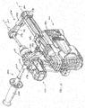
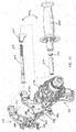
- FIGS. 17 and 18 illustrate a dust collector 410 in accordance with another embodiment of the invention for use with a hand-held rotary power tool 414 (e.g., a hammer drill).
- the dust collector 410 is substantially identical to the dust collector 110 described above and shown in FIGS. 1-16 .
- like components and features are identified with like reference numerals plus "300.”
- the dust collector 410 includes an adapter 450 and an auxiliary handle 442 for supporting the power tool 414 in a side-by-side relationship with the dust collector 410 ( FIGS. 17 and 18 ).
- the adapter 450 includes a fixed clamp member 470 and an opposed, movable clamp member 474 for clamping the adapter 450 to either side of the housing 418 ( FIG. 19 ).
- the fixed clamp member 470 is received within a first notch 482 in the housing 418
- the movable clamp member 474 is received within a second notch 478 in the housing 418 ( FIG. 18 ).
- the notches 478, 482 are defined in each side of the housing 418 to clamp the adapter 450 to either side of the housing 418.
- the adapter 450 also includes a cam 486 and a follower 490 for actuating the movable clamp member 474 between an open position in which it is displaced from the second notch 478 and disengaged from the housing 418, and a closed position in which the movable clamp member 474 is received within the second notch 478 and engaged with the housing 418.
- the cam 486 is integrally formed as a single piece with a lever 494
- the follower 490 is integrally formed as a single piece with the movable clamp member 474.
- the adapter 450 further includes a resilient member (e.g., a compression spring 498) that biases the movable clamp member 474 away from the fixed clamp member 470 and toward the open position.
- the handle 442 includes a shaft 500 extending from the adapter 450, a clamp member 504 movable along and relative to the shaft 500, a grip 508 having a threaded insert 512 engageable with a threaded portion 516 of the shaft 500, and a spacer 520 positioned between the movable clamp member 504 and the grip 508.
- the adapter 450 includes a fixed clamp member 524 opposite and in facing relationship with the movable clamp member 504.
- the clamp members 504, 524 are received in corresponding notches 528, 532 in a portion of the power tool 414 (e.g., a transmission housing 536) to thereby clamp the power tool 414 between the movable clamp member 504 and the fixed clamp member 524.
- the spacer 520 displaces the movable clamp member 504 along the shaft 500 toward the fixed clamp member 524, thereby progressively increasing the clamping force exerted on the power tool 414.
- the dust collector 410 also includes a suction head 530 longer than that shown in the dust collector 10 of FIGS. 1 and 2 to account for a greater distance between the parallel axes 502, 506 of the power tool 414 and the dust collector 410.
- the hub 534 and first arm portion 443 of the suction head 530 are used with a shroud 542 having an elongated second arm portion 444.
- the second arm portion 444 of the suction head 530 is longer than that of the suction head 230 shown in FIGS. 1 and 2 .
- the second arm portions 244, 444 with accompanying shrouds 242, 542 may be interchanged by manipulating the snap-fit between the arm portions 243, 244 and 443, 444 depending upon what type of power tool with which the dust collector 410 is used (i.e., the rotary hammer of FIGS. 1 and 2 or the hammer drill of FIGS. 17 and 18 ).
- the first arm portion 243, 244 may include multiple (i.e., at least two) detent recesses 245 ( FIG. 8 ) with which to use with the snap-fit between the arm portions 243, 244 and 443, 444 depending upon what type of power tool with which the dust collector 410 is used (i.e., the rotary hammer of FIGS.
- the arm portions 244, 444 may telescope relative to the arm portions 243, 443 in particular increments determined by the spacing between the detent recesses 245 to lengthen or shorten the suction heads 230, 530.
- a dust collector comprising:
- the filter is removably received in the dust container.
- the dust container and the filter may be removable from the housing as a unit.
- the filter may include a pleated element and a rim surrounding the pleated element, and wherein the rim is trapped between the dust container and the housing when the dust container is attached to the housing.
- the pleated element may extend into an interior of the dust container.
- the filter may be oriented relative to the dust container in an inclined or an oblique manner relative to a longitudinal axis of the suction pipe.
- the rim may be accessible for grasping to facilitate removal of the filter from the dust container when the dust container is detached from the housing.
- the filter may be a high efficiency particulate air filter.
- the dust collector further includes a detector coupled to the housing and biased toward a first position in which a portion of the detector protrudes from the housing to prevent the dust container from being coupled to the housing in absence of the filter, the protruding portion of the detector being retractable into the housing in response to the detector being moved to a second position by the filter when the filter is present, thereby permitting the dust container to be coupled to the housing.
- the detector may be pivotably supported by the housing at a location upstream of the suction fan.
- the detector may include a shaft defining a rotational axis about which the detector is pivotable and an arm extending radially from the shaft, and wherein the arm is engaged with the filter when the filter is present.
- the protruding portion may be configured as a finger positioned adjacent the arm.
- the housing may include an aperture aligned with the finger, and wherein the dust container includes an alignment tab that is receivable in the aperture when the pre-assembled filter and dust container are attached to the housing.
- the finger may be pivoted to a position in which it at least partially protrudes into the aperture in absence of the filter, thereby interfering with the alignment tab to prevent the dust container from being attached to the housing.
- the dust collector may further comprise:
- the suction pipe telescopically moves relative to the housing along a first axis
- the dust collector further includes a battery pack removably coupled to the housing along a second axis oriented substantially normal to the first axis.
- the dust collector may further comprise a switch electrically connecting the motor with a power source to activate the motor in response to detecting telescoping movement of the suction pipe relative to the housing.
- the dust collector may further comprise a handle assembly including
- a power tool assembly comprising:
- the first and second power tool battery packs may be identical.
- the power tool and the dust collector may be coupled in a side-by-side relationship
- Each of the first and second battery packs may include three lithium-ion battery cells.
- the power tool may be a rotary power tool.
- the power tool may be a rotary power tool such as rotary hammer or a hammer drill.
- a dust collector comprising:
- the handle assembly may further include
- the handle assembly may further include a third handle having a head portion with a third size for receiving a neck of a third power tool for supporting the third power tool in a side-by-side relationship with the dust collector, and wherein the necks of the first, second, and third power tools are of a different size.
- the handle assembly may further include a third adapter attached to the third handle, and wherein the third adapter interchangeably attaches the third handle to the housing.
- the housing may include a first side and an opposite second side, and wherein the first and second adapters are each interchangeably connectable to the first and second sides of the housing to thereby support one of the first and second power tools adjacent a chosen one of the first and second sides of the housing.
- Each of the first and second handles may include a cylindrical band and a rotatable grip for constricting and expanding the band, and wherein the necks of the first and second power tools are clamped by the respective bands.
- the respective cylindrical bands of the first and second handles may include different circumferential lengths.
- a dust collector comprising:
- the ruler may include a plurality of reference markings, and wherein a first of the markings is alignable with a reference datum on the housing to limit an extent to which the suction pipe telescopes into the housing to a first depth.
- a second of the markings is alignable with the reference datum on the housing to limit the extent to which the suction pipe telescopes into the housing to a second depth.
- the depth stop may be engageable with the housing to limit the extent to which the suction pipe may telescope relative to the housing.
Landscapes
- Engineering & Computer Science (AREA)
- Mechanical Engineering (AREA)
- Auxiliary Devices For Machine Tools (AREA)
- Percussive Tools And Related Accessories (AREA)
Abstract
Description
- The present invention relates to power tools, and more particularly to dust collectors for use with power tools.
- Dust collectors are typically used in tandem with hand-held drilling tools such as rotary hammers to collect dust and other debris during a drilling operation to prevent dust and other debris from accumulating at a worksite. Such dust collectors may be attached to a rotary hammer to position a suction inlet of the collector proximate a drill bit attached to the rotary hammer. Such dust collectors may also include an on-board dust container in which dust and other debris is accumulated. Such dust containers are often removable from the dust collector to facilitate disposal of the accumulated dust and debris.
- The invention provides, in one aspect, a power tool assembly including a hand-held power tool, a dust collector removably coupled to the power tool, and first and second power tool battery packs each of which is interchangeably coupled with the power tool and the dust collector for separately powering the power tool and the dust collector, respectively.
- The invention provides, in another aspect, a dust collector for use with a hand-held power tool. The dust collector includes a housing, a telescoping suction pipe coupled to the housing, an electric motor positioned in the housing, a suction fan driven by the electric motor and operable to generate a vacuum in the suction pipe, a dust container coupled to the housing and positioned upstream of the suction fan, an adapter including a first portion coupled to the housing and a second portion, and an auxiliary handle coupled to the second portion of the adapter and a neck of the power tool. The adapter and the auxiliary handle support the power tool in a side-by-side relationship with the dust collector.
- The invention provides, in yet another aspect, a dust collector for use with a hand-held power tool. The dust collector includes a housing, a telescoping suction pipe coupled to the housing, an electric motor positioned in the housing, a suction fan driven by the electric motor and operable to generate a vacuum in the suction pipe, and a switch electrically connecting the motor with a power source to activate the motor in response to detecting telescoping movement of the suction pipe relative to the housing.
- The invention provides, in a further aspect, a dust collector including a housing, a telescoping suction pipe coupled to the housing, an electric motor positioned in the housing, a suction fan driven by the electric motor and operable to generate a vacuum in the suction pipe, and a handle assembly. The handle assembly includes a first handle having a head portion with a first size for receiving a neck of a first power tool for supporting the first power tool in a side-by-side relationship with the dust collector and a second handle having a head portion with a second size for receiving a neck of a second power tool for supporting the second power tool in a side-by-side relationship with the dust collector. The necks of the first and second power tools are of a different size.
- The invention provides, in another aspect, a dust collector for use with a hand-held power tool. The dust collector includes a housing, a telescoping suction pipe coupled to the housing, an electric motor positioned in the housing, a suction fan driven by the electric motor and operable to generate a vacuum in the suction pipe, a dust container coupled to the housing and positioned upstream of the suction fan, and a filter supported by at least one of the housing and the dust container. The filter is removable from the one of the housing and the dust container for at least one of servicing and replacement.
- The invention provides, in yet another aspect, a dust collector for use with a hand-held power tool. The dust collector includes a housing, a suction pipe coupled to the housing for telescoping movement along a first axis, an electric motor positioned in the housing, a suction fan driven by the electric motor and operable to generate a vacuum in the suction pipe, and a battery pack removably coupled to the housing along a second axis oriented substantially normal to the first axis.
- The invention provides, in a further aspect, a dust collector for use with a hand-held power tool. The dust collector includes a housing, a telescoping suction pipe coupled to the housing, an electric motor positioned in the housing, a suction fan driven by the electric motor and operable to generate a vacuum in the suction pipe, a depth stop movable along the length of the suction pipe and selectively fixed to the suction pipe to limit the extent to which the suction pipe may telescope relative to the housing, and a ruler coupled for movement with the depth stop.
- The invention provides, in another aspect, a dust collector for use with a hand-held power tool. The dust collector includes a housing, a telescoping suction pipe coupled to the housing, an electric motor positioned in the housing, a suction fan driven by the electric motor and operable to generate a vacuum in the suction pipe, a dust container removably coupled to the housing in which dust may be accumulated, a filter supportable by at least one of the housing and the dust container, and a detector coupled to the housing and biased toward a first position in which a portion of the detector protrudes from the housing to prevent the container from being coupled to the housing in absence of the filter. The portion of the detector is retractable into the housing in response to the detector being moved to a second position by the filter when the filter is present, thereby permitting the container to be coupled to the housing.Other features and aspects of the invention will become apparent by consideration of the following detailed description and accompanying drawings.
-
-
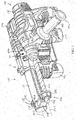
FIG. 1 is a front perspective view of a dust collector in accordance with an embodiment of the invention attached to a rotary power tool. -
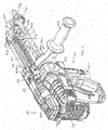
FIG. 2 is a rear perspective view of the dust collector and rotary power tool ofFIG. 1 . -
FIG. 3 is a rear perspective view of the dust collector ofFIG. 1 attached to an opposite side of the rotary power tool. -
FIG. 4 is a front perspective view of the dust collector ofFIG. 1 , illustrating a handle assembly having multiple size handles for attaching rotary power tools of different sizes. -
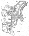
FIG. 5 is an enlarged, partial cross-sectional view of an adapter for use with any of the handles ofFIG. 4 . -
FIG. 6 is an enlarged, front perspective view of the dust collector ofFIG. 1 , illustrating a suction head rotated to a first position relative to a suction pipe. -
FIG. 7 is an enlarged, front perspective view of the dust collector ofFIG. 1 , illustrating the suction head rotated to a second position relative to the suction pipe. -
FIG. 8 is an enlarged, front perspective view of the dust collector ofFIG. 1 , illustrating the suction head and a stand-alone nozzle being interchangeably coupled to the suction pipe. -
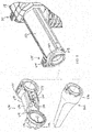
FIG. 9 is an enlarged, exploded perspective view of the dust collector ofFIG. 1 , illustrating a dust container and a filter. -
FIG. 10 is a longitudinal cross-sectional view of the dust collector ofFIG. 1 . -
FIG. 11 is an enlarged, perspective view of the dust collector ofFIG. 1 exposing the rear of the telescoping suction pipe with the suction pipe in an extended position. -
FIG. 12 is an enlarged, perspective view of the dust collector ofFIG. 1 exposing the rear of the telescoping suction pipe with the suction pipe in a retracted position. -
FIG. 13 is an enlarged, cross-sectional view of the dust collector ofFIG. 1 illustrating an extension stop secured to the telescoping suction pipe. -
FIG. 14 is an enlarged, perspective view of the dust collector ofFIG. 1 illustrating a plunge depth stop with an attached ruler that are movable as a unit relative to the suction pipe. -
FIG. 15 is an enlarged, cross-sectional view of the dust collector ofFIG. 1 illustrating the plunge depth stop secured to the telescoping suction pipe. -
FIG. 16 is an enlarged, perspective view of the dust collector ofFIG. 1 illustrating a cutaway to expose a detector that prevents attachment of a dust container to the housing of the dust collector without an accompanying filter. -
FIG. 17 is a front perspective view of a dust collector in accordance with yet another embodiment of the invention attached to a rotary power tool. -
FIG. 18 is a rear perspective view of the dust collector and rotary power tool ofFIG. 17 . -
FIG. 19 is an exploded, front perspective view of the dust collector and rotary power tool ofFIG. 17 . - Before any embodiments of the invention are explained in detail, it is to be understood that the invention is not limited in its application to the details of construction and the arrangement of components set forth in the following description or illustrated in the following drawings. The invention is capable of other embodiments and of being practiced or of being carried out in various ways. Also, it is to be understood that the phraseology and terminology used herein is for the purpose of description and should not be regarded as limiting.
-
FIGS. 1 and2 illustrate adust collector 110 in accordance with an embodiment of the invention for use with a hand-held rotary power tool 114 (e.g., a rotary hammer). As will be described in more detail below, thedust collector 110 is operable to collect dust and other debris from a workpiece during a drilling and/or hammering operation performed by thepower tool 114 to maintain the user's work area substantially clear of dust. - The
dust collector 110 includes ahousing 118, atelescoping suction pipe 122 coupled to thehousing 118, anelectric motor 126 positioned in the housing 118 (FIG. 10 ), asuction fan 130 driven by theelectric motor 126 and operable to generate a vacuum in thesuction pipe 122, and adust container 134 coupled to thehousing 118 and positioned upstream of thesuction fan 130. With reference toFIGS. 1 and3 , thedust collector 110 includes ahandle assembly 138 that supports thepower tool 114 in a side-by-side relationship with thedust collector 110. Particularly, thehandle assembly 138 may be attached to either side of thehousing 118 depending upon which side of thedust collector 110 the user wants to position thepower tool 114. - With reference to
FIG. 4 , thehandle assembly 138 includesmultiple handles 142a, 142b, 142c having respective head portions 146a, 146b, 146c of a different size to accommodatepower tools 114 of corresponding sizes, and respective adapters 150a, 150b, 150c for securing thehandles 142a-142c to thehousing 118. In the illustrated embodiment of thehandle assembly 138, threehandles 142a-142c are shown each having a head portion 146a-146c of a different size in which a correspondingsized neck 154 on thepower tool 114 is clamped. Alternatively, thehandle assembly 138 may include more orfewer handles 142a-142c of different sizes. Each of thehandles 142a-142c includes acylindrical band 158a, 158b, 158c that is constricted and expanded by rotating agrip 162 on thehandle 142a-142c in opposite directions. Thebands 158a, 158b, 158c include different circumferential lengths to accommodatepower tools 114 having correspondingsized necks 154. The adapters 150a-150c each include anarcuate slot 166 in which a portion of the band 158a-158c is received (FIG. 5 ). Accordingly, the adapters 150a-150c are connected to the head portions 146a-146c as a unit. In an alternative embodiment of thehandle assembly 138, only asingle grip 162 may be provided for interchangeable use with any of the head portions 146a-146c. For example, to exchange any of thehandles 142a-142c for another, thegrip 162 may be unthreaded from one of the head portions 146a-146c and threaded to another of the head portions 146a-146c. - With continued reference to
FIG. 5 , the adapter 150 includes a fixedclamp member 170 and an opposed,movable clamp member 174 for clamping the adapter 150 to either side of thehousing 118. Particularly, the fixedclamp member 170 is received within afirst notch 178 in thehousing 118, and themovable clamp member 174 is received within a second notch 182 in thehousing 118. Thenotches 178, 182 are defined in each side of thehousing 118 to clamp the adapter 150 to either side of thehousing 118. In the illustrated embodiment of thedust collector 110, ametal reinforcing plate 183 is insert molded with thehousing 118 between thenotches 178, 182 such that theclamp members top edges 184, 185 of theplate 183, respectively. Alternatively, theplate 183 may be omitted. - The adapter 150 also includes a cam 186 and a
follower 190 for actuating themovable clamp member 174 between an open position in which it is displaced from the second notch 182 and disengaged from thehousing 118, and a closed position in which themovable clamp member 174 is received within the second notch 182 and engaged with the housing 118 (FIG. 5 ). In the illustrated embodiment of the adapter 150, the cam 186 is integrally formed as a single piece with alever 194, and thefollower 190 is integrally formed as a single piece with themovable clamp member 174. The adapter 150 further includes a resilient member (e.g., a compression spring 198) that biases themovable clamp member 174 away from the fixedclamp member 170 and toward the open position. - The
handles 142a-142c are sized to maintain a generally consistent spacing betweenparallel axes power tool 114 and thedust collector 110, respectively (FIG. 4 ) so that atool bit 210 attached to achuck 214 of the power tool 114 (FIGS. 1-3 ), irrespective of the size of theparticular power tool 114 used with thedust collector 110, is positioned in the same location relative to thedust collector 110. - With continued reference to
FIGS. 1-3 , thedust collector 110 and thepower tool 114 include respective power tool battery packs 218, 222, each of which may be interchangeably coupled with thepower tool 114 and thedust collector 110 for separately powering thepower tool 114 and thedust collector 110, respectively. In other words, thedust collector 110 and thepower tool 114 may be independently powered using identical battery packs 218, 222_ Such battery packs 218, 222 may be 12-volt power tool battery packs 218, 222 that include three lithium-ion battery cells. Alternatively, the battery packs 218, 222 may each include fewer or more battery cells to yield any of a number of different output voltages (e.g., 14.4 volts, 18 volts, etc.). Additionally or alternatively, the battery cells may include chemistries other than lithium-ion such as, for example, nickel cadmium, nickel metal-hydride, or the like. - With reference to
FIG. 10 , thebattery pack 218 is removably coupled to thedust collector 118 housing along anaxis 226 that is oriented substantially normal to theaxis 206 of thedust collector 110. As such, thebattery pack 218 is substantially isolated from the axial impacts imparted by thepower tool 114 along thepower tool axis 202. In an alternative embodiment of thedust collector 110 in which such axial impacts imparted by thepower tool 114 are not of concern, thebattery pack 218 may be oriented substantially parallel with theaxis 206 of thedust collector 110. - With reference to
FIGS. 1-3 , thedust collector 110 includes asuction head 230 coupled to the end of thesuction pipe 122. Thesuction head 230 includes ahub 234, ahollow arm 238 extending from a side of thehub 234, and ashroud 242 coupled to the end of thearm 238. In the illustrated embodiment of thedust collector 110, thearm 238 includes afirst portion 243 integrally formed with thehub 234 and asecond portion 244 integrally formed with the shroud 242 (FIG. 8 ). Thesecond portion 244 is received in thefirst portion 243 by way of a snap-fit; however, thesecond portion 244 may be retained to thefirst portion 243 in any of a number of different ways. - The
shroud 242 defines a stepped suction inlet 246 (FIG. 1 ) through which air is drawn in during operation of thedust collector 110. When thesuction inlet 246 is in contact with a workpiece during a drilling operation, theshroud 242 encloses a portion of thetool bit 210 and the surrounding region of the work piece to maintain the region at a sub-atmospheric pressure. In other words, the vacuum created in thesuction pipe 122 and thesuction head 230 draws dust and other debris generated during the drilling and/or hammering operation from theshroud 242, through thesuction pipe 122, for depositing in thecontainer 134. - As shown in
FIGS. 6 and 7 , thesuction head 230 may be attached to thesuction pipe 122 in two different orientations to accommodate placement of thepower tool 114 on both sides of thedust collector 110. Adetent arrangement 250 is utilized to maintain thesuction head 230 in either of the positions shown inFIGS. 6 and 7 . Particularly, thedetent arrangement 250 includes twodetent members 254 formed on thearm 238 and twodetent recesses 258 located on opposite sides of the suction pipe 122 (with respect to the axis 206). In the illustrated embodiment of thedetent arrangement 250, thedetent members 254 are radially extending ribs integrally formed with thearm 238, and the detent recesses 258 are defined in anend cap 262 attached to the end of thesuction pipe 122. When thedetent members 254 are received in theirrespective recesses 258, thesuction head 230 is rigidly maintained in position. To re-orient thesuction head 230 from one side of thesuction pipe 122 to the other, the user of thedust collector 110 needs only to apply a slight torque or a rotational force to thesuction head 230 to overcome the friction between thedetent members 254 and theend cap 262 for removing thedetent member 254 from itsrespective detent recess 258. Alternatively, thedetent arrangement 250 may be configured in any of a number of different ways for securing thesuction head 230 in the positions shown inFIGS. 6 and 7 . - With reference to
FIG. 8 , thedust collector 110 includes anozzle 266 interchangeably coupled to thesuction pipe 122 with thesuction head 230. Particularly, thenozzle 266 includes ahub 270 having an identical configuration as thehub 234 of thesuction head 230. As such, thenozzle 266 is attachable and removable from thesuction pipe 122 in the same manner as thesuction head 230. As is described in more detail below, thenozzle 266 facilitates usage of thedust collector 110 without thepower tool 114 as a stand-alone vacuum device. - With reference to
FIGS. 14 and15 , thedust collector 110 includes a plunge depth stop 274 movable along the length of thesuction pipe 122 and selectively fixed to thesuction pipe 122 to limit the extent to which thesuction pipe 122 may telescope relative to thehousing 118. Thesuction pipe 122 includes arail 278 along which thedepth stop 274 is movable, and adetent plate 282 including spacedapertures 286 along the length of theplate 282 is received within therail 278. Thedepth stop 274 includes a pin 290 (FIG. 15 ) that is receivable in one of theapertures 286 in thedetent plate 282 to secure thedepth stop 274 to thesuction pipe 122, and anactuator 294 for selectively moving thepin 290 relative to thedetent plate 282 for inserting and removing thepin 290 from one of theapertures 286. Thepin 290 is normally biased away from thedetent plate 282 by a resilient member (e.g., a compression spring 298). Likewise, theactuator 294 is normally biased upward from the frame of reference ofFIG. 15 by a resilient member (e.g., a compression spring 302). Theactuator 294 includes a cam profile 306 which, in response to theactuator 294 being released from an initial depressed position, displaces thepin 290 toward thedetent plate 282 against the bias of the spring 298. To reposition the depth stop 274 relative to thesuction pipe 122, theactuator 294 is depressed against the bias of thespring 302 until the cam profile 306 is aligned with thepin 290, thereby permitting thepin 290 to be pushed away from the detent plate 282 (thereby removing thepin 290 from one of the apertures 286) by the spring 298. - With reference to
FIG. 14 , thedust collector 110 also includes aruler 310 coupled for movement with thedepth stop 274. As such, the plunge depth of thesuction tube 122 may be set with reference to markings on theruler 310 and areference datum 312 on the housing 118 (e.g., a line or edge on the front of thehousing 118 surrounding the suction pipe 122). For example, should the user of thedust collector 110 and thepower tool 114 desire to plunge thetool bit 210 only two inches into a workpiece, the user would slide the depth stop 274 relative to thesuction tube 122 until the "2 inch" marking on theruler 310 is in alignment with thereference datum 312 on thehousing 118. Thereafter, thesuction pipe 122 is limited to retracting only two inches into thehousing 118 before the depth stop 274 contacts thehousing 118 at which time further retraction of thesuction pipe 122 is halted. - With reference to
FIG. 11 , thedust collector 110 includes anextension stop 314 movable along the length of thesuction pipe 122 and selectively fixed to thesuction pipe 122 to limit the extent to which thesuction pipe 122 may extend from the housing 118 (i.e., by contacting an interior surface of the housing 118). Particularly, theextension stop 314 is nearly structurally identical to theplunge depth stop 274 and therefore may be selectively secured along therail 278 of thesuction tube 122 in a similar manner as theplunge depth stop 274. However, theextension stop 314 includes a two-piece actuator 318 with a first portion 322 (which includes the cam profile) being attached with the remainder of the extension stop 314 to thesuction pipe 122 for telescoping movement with thesuction pipe 122, and asecond portion 326 that is stationary on thehousing 118. Thesecond portion 326 includes a plunger 330 that is engageable with thefirst portion 322 to release the extension stop 314 from thesuction pipe 122. A resilient member (e.g., a compression spring 334) biases thesecond portion 326 of theactuator 318 upward from the frame of reference ofFIG. 11 such that thesecond portion 326 is normally clear of the remainder of the extension stop 314 as thestop 314 moves with extension and retraction of thesuction pipe 122. - With reference to
FIGS. 11 and12 , thedust collector 110 further includes afirst switch 338 electrically connecting themotor 126 with a power source (e.g., the battery pack 218) to activate themotor 126 in response to detecting telescoping movement of thesuction pipe 122 relative to thehousing 118. Thedust collector 110 also includes a controller (not shown) electrically connected between theswitch 338 and thebattery pack 218, and a second switch 342 (FIG. 2 ) electrically connected with themotor 126, thebattery pack 218, and thefirst switch 338 via the controller. Thesecond switch 342 is toggled between a first switching position in which theelectric motor 126 remains deactivated irrespective of actuation of thefirst switch 338, a second switching position in which theelectric motor 126 may be activated and deactivated automatically in response to actuation of thefirst switch 338, and a third switching position in
which theelectric motor 126 may be activated irrespective of actuation of thefirst switch 338. In the illustrated embodiment of thedust collector 110, thesecond switch 342 is configured as a slide switch. Alternatively, thesecond switch 342 may be configured in any of a number of different ways to accommodate the first, second, and third switching positions. Thesecond switch 342 may be toggled to either of the first switching position or the third switching position when using thedust collector 110 as a stand-alone unit in conjunction with the stand-alone nozzle 266 shown inFIG. 8 . The first, second, and third switching positions of thesecond switch 342 may occur in any sequential order depending upon the configuration of theswitch 342. - In the illustrated embodiment of the
dust collector 110 shown inFIG. 11 , with thesecond switch 342 toggled to the second or "automatic" switching position, the first switch 338 (e.g., a microswitch configured as a normally closed switch) is maintained in an open state when contacted by theextension stop 314. As such, the controller will not supply current from thebattery pack 218 to themotor 126 to activate themotor 126 so long as thesuction pipe 122 is fully extended from thehousing 118, at least to an extent permitted by theextension stop 314. However, in response to thesuction pipe 122 retracting into the housing 118 (which is indicative of the start of a drilling operation by the power tool 114), thefirst switch 338 detects this movement when it loses contact with theextension stop 314, thereby actuating thefirst switch 338 to a closed state. The controller then supplies current from thebattery pack 218 to themotor 126 to activate themotor 126 to draw a vacuum through thesuction pipe 122 and thesuction head 230 as long as thesuction pipe 122 remains in a retracted position relative to thehousing 118. - In a first manner of operating the
dust collector 110, the controller initiates a timer upon thefirst switch 338 detecting movement of thesuction pipe 122 from the fully extended position to a retracted position. If thesuction pipe 122 is maintained in a retracted position for a predetermined amount of time (e.g., at least one second), the controller maintains activation of themotor 126 for another predetermined amount of time (e.g., four seconds) subsequent to thesuction pipe 122 returning to its fully extended position so that dust and other debris within thesuction pipe 122 may be cleared and deposited in thedust container 134 after completion of a drilling operation and removal of thedust collector 110 from the workpiece. If thesuction pipe 122 is not maintained in a retracted position for at least one second, for example, the controller immediately deactivates themotor 126 in response to thesuction pipe 122 returning to its fully extended position. - In a second manner of operating the
dust collector 110, rather than immediately activating themotor 126 in response to retraction of thesuction pipe 122, the controller initiates a timer upon thefirst switch 338 detecting movement of thesuction pipe 122 from the fully extended position to a retracted position. The controller activates themotor 126 only after a predetermined amount of time (e.g., a fraction of a second) lapses with thesuction pipe 122 maintained in the retracted position. As a result, inadvertent "bumps" or contact with thesuction pipe 122 that might otherwise cause slight retraction of thesuction pipe 122 are ignored by the controller, thereby maintaining themotor 126 in a deactivated state and conserving power in thebattery pack 218. - Also, rather than immediately deactivating the
motor 126 when thesuction pipe 122 is returned to its fully extended position, the controller maintains activation of themotor 126 for a period of time (e.g., a fraction of a second or more) in response to thefirst switch 338 resuming contact with theextension stop 314, at which time thefirst switch 338 is actuated to an open state. As a result, dust and other debris within thesuction pipe 122 may be cleared and deposited in thedust container 134 after completion of a drilling operation and removal of thedust collector 110 from the workpiece. - With reference to
FIG. 9 , thedust collector 110 includes a filter 346 supported by at least one of thehousing 118 and thedust container 134. In the illustrated embodiment of thedust collector 110, the filter 346 includes aplastic housing 348, apleated element 350 within thehousing 348, and arim 354 surrounding thepleated element 350. Therim 354 is trapped between thedust container 134 and thehousing 118 when thedust container 134 is attached to thehousing 118. Alternatively, thedust collector 134 may incorporate additional structure for securing the filter 346 to thedust container 134 prior to thedust container 134 being attached to thehousing 118. When thedust container 134 is removed from thehousing 118, the filter 346 is accessible and removable from thedust container 134 for servicing and/or replacement by merely pulling the filter 346 (by, for example, grasping the rim 354) from thedust container 134
after thedust container 134 has been removed or detached from thehousing 118. The filter 346 may be configured as a high efficiency particulate air ("HEPA") filter 346. - With reference to
FIG. 10 , the filter 346 is oriented within thedust container 134 in an inclined or an oblique manner relative to theaxis 206 of thedust collector 110. As such, it is expected that at least a portion of the filter 346 will remain exposed when thedust container 134 is nearly filled with dust, regardless of the orientation of thedust collector 110 while in use. Particularly, thepleated element 350 of the filter 346 extends into the interior of thedust container 134, and at least a portion of thepleated element 350 is expected to remain exposed when thedust container 134 is nearly filled with dust, regardless of the orientation of thedust collector 110 while in use. Optionally, thedust collector 110 may include a secondary filter (e.g., a porous plate, a screen, etc.) positioned between thefan 130 and the filter 346 to inhibit particles that may have bypassed the filter 346 from being impacted by thefan 130. Such a secondary filter may be permanently affixed to thehousing 118 and non-removable from thehousing 118. Such a secondary filter may also include a fine pore size, such that any particles bypassing both the filter 346 and the secondary filter are sufficiently small to not damage thefan 130. - With reference to
FIG. 16 , thedust collector 110 includes adetector 358 coupled to thehousing 118 and biased toward a first position in which afirst arm 362 of thedetector 358 protrudes from thehousing 118 to prevent thedust container 134 from being coupled to thehousing 118 in absence of the filter 346. Thefirst arm 362 is retractable into thehousing 118 in response to thedetector 358 being moved to a second position by the filter 346 when the filter 346 is present, thereby permitting thecontainer 134 to be coupled to thehousing 118. Particularly, in the illustrated embodiment of thedust collector 110, thedetector 358 is pivotably supported by thehousing 118 at a location upstream of thesuction fan 130. Thedetector 358 includes ashaft 366 defining arotational axis 370 about which thedetector 358 is pivotable, thefirst arm 362 that extends radially from theshaft 366, afinger 374 positioned adjacent thefirst arm 362, and asecond arm 378 that extends radially from theshaft 366 and that is axially spaced from thefirst arm 362. Thedetector 358 is configured as a single, unitary component. Alternatively, the various features of thedetector 358, including thefirst arm 362, thesecond arm 378, and thefinger 374, may be separate from each other. - The
first arm 362 is located on theshaft 366 such that thefirst arm 362 is generally aligned with one of the segments of therim 354 when the filter 346 is situated in an installed position in thedust container 134. As such, when the pre-assembled filter 346 anddust container 134 are moved into position for attachment to thehousing 118, thefirst arm 362 is engaged by therim 354, therefore causing thedetector 358 to pivot about theaxis 370. A resilient member (e.g., a compression spring, not shown) is positioned between thehousing 118 and thesecond arm 378 for biasing thedetector 358 to a position in which thefirst arm 362 protrudes from thehousing 118 in absence of the filter 346_ - With continued reference to
FIG. 16 , thefinger 374 is in alignment with a window or anaperture 382 in thehousing 118 through which analignment 386 tab on thedust container 134 is receivable when the pre-assembled filter 346 anddust container 134 are attached to thehousing 118. In absence of the filter 346 anddust container 134, the spring biases thefinger 374 to a pivoted position in which it at least partially protrudes into the aperture 182. Should the user of thedust collector 110 attempt to attach thedust container 134 without the filter 346 being in position, the spring will maintain theshaft 366 in a pivoted position in which thefirst arm 362 protrudes from thehousing 118 and thefinger 374 at least partially protrudes into theaperture 382. As such, thefinger 374 prevents thealignment tab 386 from being received in theaperture 382, thereby preventing attachment of thedust container 134 to thehousing 118. - However, when the pre-assembled filter 346 and
dust container 134 are moved into position for attachment to thehousing 118, thefirst arm 362 is engaged by therim 354, thereby causing theshaft 366 to pivot about theaxis 370 and remove thefinger 374 from theaperture 382. Thealignment tab 386 on thedust container 134 may then be fully received within theaperture 382 for attaching and subsequently securing thedust container 134 to thehousing 118. -
FIGS. 17 and18 illustrate adust collector 410 in accordance with another embodiment of the invention for use with a hand-held rotary power tool 414 (e.g., a hammer drill). Thedust collector 410 is substantially identical to thedust collector 110 described above and shown inFIGS. 1-16 . As such, like components and features are identified with like reference numerals plus "300." - The
dust collector 410 includes anadapter 450 and anauxiliary handle 442 for supporting thepower tool 414 in a side-by-side relationship with the dust collector 410 (FIGS. 17 and18 ). Theadapter 450 includes a fixedclamp member 470 and an opposed, movable clamp member 474 for clamping theadapter 450 to either side of the housing 418 (FIG. 19 ). Particularly, the fixedclamp member 470 is received within afirst notch 482 in thehousing 418, and the movable clamp member 474 is received within a second notch 478 in the housing 418 (FIG. 18 ). Thenotches 478, 482 are defined in each side of thehousing 418 to clamp theadapter 450 to either side of thehousing 418. With reference toFIG. 19 , theadapter 450 also includes acam 486 and afollower 490 for actuating the movable clamp member 474 between an open position in which it is displaced from the second notch 478 and disengaged from thehousing 418, and a closed position in which the movable clamp member 474 is received within the second notch 478 and engaged with thehousing 418. In the illustrated embodiment of theadapter 450, thecam 486 is integrally formed as a single piece with alever 494, and thefollower 490 is integrally formed as a single piece with the movable clamp member 474. Theadapter 450 further includes a resilient member (e.g., a compression spring 498) that biases the movable clamp member 474 away from the fixedclamp member 470 and toward the open position. - With continued reference to
FIG. 19 , thehandle 442 includes ashaft 500 extending from theadapter 450, aclamp member 504 movable along and relative to theshaft 500, agrip 508 having a threaded insert 512 engageable with a threadedportion 516 of theshaft 500, and aspacer 520 positioned between themovable clamp member 504 and thegrip 508. Theadapter 450 includes a fixedclamp member 524 opposite and in facing relationship with themovable clamp member 504. Theclamp members corresponding notches 528, 532 in a portion of the power tool 414 (e.g., a transmission housing 536) to thereby clamp thepower tool 414 between themovable clamp member 504 and the fixedclamp member 524. Particularly, as thegrip 508 is threaded to the shaft 500 (i.e., via the threaded insert 512), thespacer 520 displaces themovable clamp member 504 along theshaft 500 toward the fixedclamp member 524, thereby progressively increasing the clamping force exerted on thepower tool 414. - With reference to
FIGS. 17 and18 , thedust collector 410 also includes asuction head 530 longer than that shown in the dust collector 10 ofFIGS. 1 and2 to account for a greater distance between theparallel axes power tool 414 and thedust collector 410. Particularly, thehub 534 and first arm portion 443 of thesuction head 530 are used with ashroud 542 having an elongated second arm portion 444. In other words, the second arm portion 444 of thesuction head 530 is longer than that of thesuction head 230 shown inFIGS. 1 and2 . Thesecond arm portions 244, 444 with accompanyingshrouds arm portions dust collector 410 is used (i.e., the rotary hammer ofFIGS. 1 and2 or the hammer drill ofFIGS. 17 and18 ). Alternatively, thefirst arm portion FIG. 8 ) with which to use with the snap-fit between thearm portions dust collector 410 is used (i.e., the rotary hammer ofFIGS. 1 and2 or the hammer drill ofFIGS. 17 and18 ). Accordingly, thearm portions 244, 444 may telescope relative to thearm portions 243, 443 in particular increments determined by the spacing between the detent recesses 245 to lengthen or shorten the suction heads 230, 530. - Various aspects and features of the invention are set forth below and in the following claims.
- A dust collector comprising:
- a housing;
- a telescoping suction pipe coupled to the housing;
- an electric motor positioned in the housing;
- a suction fan driven by the electric motor and operable to generate a vacuum in the suction pipe;
- a dust container coupled to the housing and positioned upstream of the suction fan; and
- a filter supported by at least one of the housing and the dust container, the filter being removable from the one of the housing and the dust container for at least one of servicing and replacement.
- In some embodiments the filter is removably received in the dust container.
- The dust container and the filter may be removable from the housing as a unit.
- The filter may include a pleated element and a rim surrounding the pleated element, and wherein the rim is trapped between the dust container and the housing when the dust container is attached to the housing.
- The pleated element may extend into an interior of the dust container.
- The filter may be oriented relative to the dust container in an inclined or an oblique manner relative to a longitudinal axis of the suction pipe.
- The rim may be accessible for grasping to facilitate removal of the filter from the dust container when the dust container is detached from the housing.
- The filter may be a high efficiency particulate air filter.
- In some embodiments the dust collector further includes a detector coupled to the housing and biased toward a first position in which a portion of the detector protrudes from the housing to prevent the dust container from being coupled to the housing in absence of the filter, the protruding portion of the detector being retractable into the housing in response to the detector being moved to a second position by the filter when the filter is present, thereby permitting the dust container to be coupled to the housing.
- The detector may be pivotably supported by the housing at a location upstream of the suction fan.
- The detector may include a shaft defining a rotational axis about which the detector is pivotable and an arm extending radially from the shaft, and wherein the arm is engaged with the filter when the filter is present.
- The protruding portion may be configured as a finger positioned adjacent the arm.
- The housing may include an aperture aligned with the finger, and wherein the dust container includes an alignment tab that is receivable in the aperture when the pre-assembled filter and dust container are attached to the housing.
- The finger may be pivoted to a position in which it at least partially protrudes into the aperture in absence of the filter, thereby interfering with the alignment tab to prevent the dust container from being attached to the housing.
- The dust collector may further comprise:
- an adapter including a first portion coupled to the housing and a second portion; and
- an auxiliary handle coupled to the second portion of the adapter and a power tool, the adapter and the auxiliary handle supporting the power tool in a side-by-side relationship with the dust collector.
- In some embodiment the suction pipe telescopically moves relative to the housing along a first axis, and wherein the dust collector further includes a battery pack removably coupled to the housing along a second axis oriented substantially normal to the first axis.
- The dust collector may further comprise a switch electrically connecting the motor with a power source to activate the motor in response to detecting telescoping movement of the suction pipe relative to the housing.
- The dust collector may further comprise a handle assembly including
- a first handle having a head portion with a first size for receiving a neck of a first power tool for supporting the first power tool in a side-by-side relationship with the dust collector, and
- a second handle having a head portion with a second size for receiving a neck of a second power tool for supporting the second power tool in a side-by-side relationship with the dust collector, the necks of the first and second power tools being of a different size.
- A power tool assembly, comprising:
- a hand-held power tool;
- a dust collector removably coupled to the power tool; and
- first and second power tool battery packs each of which is interchangeably coupled with the power tool and the dust collector for separately powering the power tool and the dust collector, respectively.
- The first and second power tool battery packs may be identical.
- The power tool and the dust collector may be coupled in a side-by-side relationship
- Each of the first and second battery packs may include three lithium-ion battery cells.
- The power tool may be a rotary power tool.
- The power tool may be a rotary power tool such as rotary hammer or a hammer drill.
- A dust collector comprising:
- a housing;
- a telescoping suction pipe coupled to the housing;
- an electric motor positioned in the housing;
- a suction fan driven by the electric motor and operable to generate a vacuum in the suction pipe; and
- a handle assembly including
- a first handle having a head portion with a first size for receiving a neck of a first power tool for supporting the first power tool in a side-by-side relationship with the dust collector, and
- a second handle having a head portion with a second size for receiving a neck of a second power tool for supporting the second power tool in a side-by-side relationship with the dust collector, the necks of the first and second power tools being of a different size.
- The handle assembly may further include
- a first adapter attached to the first handle, and
- a second adapter attached to the second handle, wherein the first and second adapters interchangeably attach the respective first and second handles to the housing.
- The handle assembly may further include a third handle having a head portion with a third size for receiving a neck of a third power tool for supporting the third power tool in a side-by-side relationship with the dust collector, and wherein the necks of the first, second, and third power tools are of a different size.
- The handle assembly may further include a third adapter attached to the third handle, and wherein the third adapter interchangeably attaches the third handle to the housing.
- The housing may include a first side and an opposite second side, and wherein the first and second adapters are each interchangeably connectable to the first and second sides of the housing to thereby support one of the first and second power tools adjacent a chosen one of the first and second sides of the housing.
- Each of the first and second handles may include a cylindrical band and a rotatable grip for constricting and expanding the band, and wherein the necks of the first and second power tools are clamped by the respective bands.
- The respective cylindrical bands of the first and second handles may include different circumferential lengths.
- A dust collector comprising:
- a housing;
- a telescoping suction pipe coupled to the housing;
- an electric motor positioned in the housing;
- a suction fan driven by the electric motor and operable to generate .i vacuum in the suction pipe;
- a depth stop movable along the length of the suction pipe and selectively fixed to the suction pipe to limit the extent to which the suction pipe may telescope relative to the housing; and
- a ruler coupled for movement with the depth stop.
- The ruler may include a plurality of reference markings, and wherein a first of the markings is alignable with a reference datum on the housing to limit an extent to which the suction pipe telescopes into the housing to a first depth.
- In some embodiments a second of the markings is alignable with the reference datum on the housing to limit the extent to which the suction pipe telescopes into the housing to a second depth.
- The depth stop may be engageable with the housing to limit the extent to which the suction pipe may telescope relative to the housing.
Claims (13)
- A power tool assembly, comprising:a hand-held power tool;a dust collector removably coupled to the power tool; andfirst and second power tool battery packs each of which is interchangeably coupled with the power tool and the dust collector for separately powering the power tool and the dust collector, respectively.
- The power tool assembly of claim 1, wherein the first and second power tool battery packs are identical.
- The power tool assembly of claim 1, wherein the power tool and the dust collector are coupled in a side-by-side relationship.
- The power tool assembly of claim 1, wherein each of the first and second battery packs includes three lithium-ion battery cells.
- The power tool assembly of claim 1, wherein the power tool is a rotary power tool.
- The power tool assembly of claim 5, wherein the rotary power tool is one of a rotary hammer and a hammer drill.
- A dust collector comprising:a housing;a telescoping suction pipe coupled to the housing;an electric motor positioned in the housing;a suction fan driven by the electric motor and operable to generate a vacuum in the suction pipe; anda handle assembly includinga first handle having a head portion with a first size for receiving a neck of a first power tool for supporting the first power tool in a side-by-side relationship with the dust collector, anda second handle having a head portion with a second size for receiving a neck of a second power tool for supporting the second power tool in a side-by-side relationship with the dust collector, the necks of the first and second power tools being of a different size.
- The dust collector of claim 7, wherein the handle assembly further includesa first adapter attached to the first handle, anda second adapter attached to the second handle, wherein the first and second adapters interchangeably attach the respective first and second handles to the housing.
- The dust collector of claim 8, wherein the handle assembly further includes a third handle having a head portion with a third size for receiving a neck of a third power tool for supporting the third power tool in a side-by-side relationship with the dust collector, and wherein the necks of the first, second, and third power tools are of a different size.
- The dust collector of claim 9, wherein the handle assembly further includes a third adapter attached to the third handle, and wherein the third adapter interchangeably attaches the third handle to the housing.
- The dust collector of claim 8, wherein the housing includes a first side and an opposite second side, and wherein the first and second adapters are each interchangeably connectable to the first and second sides of the housing to thereby support one of the first and second power tools adjacent a chosen one of the first and second sides of the housing.
- The dust collector of claim 8, wherein each of the first and second handles includes a cylindrical band and a rotatable grip for constricting and expanding the band, and wherein the necks of the first and second power tools are clamped by the respective bands.
- The dust collector of claim 12, wherein the respective cylindrical bands of the first and second handles include different circumferential lengths.
Applications Claiming Priority (6)
| Application Number | Priority Date | Filing Date | Title |
|---|---|---|---|
| US201261611003P | 2012-03-14 | 2012-03-14 | |
| US201261611417P | 2012-03-15 | 2012-03-15 | |
| US201261654296P | 2012-06-01 | 2012-06-01 | |
| US13/604,674 US9776296B2 (en) | 2008-05-09 | 2012-09-06 | Power tool dust collector |
| EP15174169.1A EP2952292B1 (en) | 2012-03-14 | 2013-03-14 | Power tool dust collector |
| EP13159268.5A EP2639010B1 (en) | 2012-03-14 | 2013-03-14 | Power tool dust collector |
Related Parent Applications (3)
| Application Number | Title | Priority Date | Filing Date |
|---|---|---|---|
| EP15174169.1A Division EP2952292B1 (en) | 2012-03-14 | 2013-03-14 | Power tool dust collector |
| EP15174169.1A Division-Into EP2952292B1 (en) | 2012-03-14 | 2013-03-14 | Power tool dust collector |
| EP13159268.5A Division EP2639010B1 (en) | 2012-03-14 | 2013-03-14 | Power tool dust collector |
Publications (2)
| Publication Number | Publication Date |
|---|---|
| EP3222386A1 true EP3222386A1 (en) | 2017-09-27 |
| EP3222386B1 EP3222386B1 (en) | 2019-12-04 |
Family
ID=47913012
Family Applications (3)
| Application Number | Title | Priority Date | Filing Date |
|---|---|---|---|
| EP13159268.5A Active EP2639010B1 (en) | 2012-03-14 | 2013-03-14 | Power tool dust collector |
| EP17170489.3A Active EP3222386B1 (en) | 2012-03-14 | 2013-03-14 | Power tool dust collector |
| EP15174169.1A Active EP2952292B1 (en) | 2012-03-14 | 2013-03-14 | Power tool dust collector |
Family Applications Before (1)
| Application Number | Title | Priority Date | Filing Date |
|---|---|---|---|
| EP13159268.5A Active EP2639010B1 (en) | 2012-03-14 | 2013-03-14 | Power tool dust collector |
Family Applications After (1)
| Application Number | Title | Priority Date | Filing Date |
|---|---|---|---|
| EP15174169.1A Active EP2952292B1 (en) | 2012-03-14 | 2013-03-14 | Power tool dust collector |
Country Status (2)
| Country | Link |
|---|---|
| US (5) | US9776296B2 (en) |
| EP (3) | EP2639010B1 (en) |
Cited By (2)
| Publication number | Priority date | Publication date | Assignee | Title |
|---|---|---|---|---|
| CN110228044A (en) * | 2018-12-09 | 2019-09-13 | 苏州欧圣电气股份有限公司 | A kind of power tool external member |
| DE102024112009A1 (en) | 2023-06-13 | 2024-12-19 | Makita Corporation | DUST COLLECTION SYSTEM FOR A POWER TOOL |
Families Citing this family (76)
| Publication number | Priority date | Publication date | Assignee | Title |
|---|---|---|---|---|
| US12629789B2 (en) | 2008-05-09 | 2026-05-19 | Milwaukee Electric Tool Corporation | Power tool dust collector |
| US9776296B2 (en) | 2008-05-09 | 2017-10-03 | Milwaukee Electric Tool Corporation | Power tool dust collector |
| JP5657436B2 (en) * | 2011-03-16 | 2015-01-21 | 株式会社マキタ | Work tools |
| JP5854811B2 (en) * | 2011-12-19 | 2016-02-09 | Dmg森精機株式会社 | Machine Tools |
| US9956676B2 (en) * | 2013-01-09 | 2018-05-01 | Techtronic Power Tools Technology Limited | Tool with rotatable head |
| JP6033698B2 (en) * | 2013-02-01 | 2016-11-30 | 株式会社マキタ | Electric tool |
| US20150328764A1 (en) * | 2013-02-01 | 2015-11-19 | Makita Corporation | Power tool |
| USD719806S1 (en) * | 2013-06-27 | 2014-12-23 | Robert Bosch Gmbh | Hammer drill accessory |
| DE102013215792B4 (en) | 2013-08-09 | 2024-01-04 | Robert Bosch Gmbh | Hand-held power tool suction device |
| CN203471741U (en) * | 2013-09-13 | 2014-03-12 | 王国雄 | Electric drill adapter |
| CN103537729B (en) * | 2013-09-26 | 2015-10-21 | 江苏苏美达五金工具有限公司 | There is the hand-held drilling machine of dust arrester |
| EP3549723A1 (en) | 2013-10-21 | 2019-10-09 | Techtronic Power Tools Technology Limited | An accessory for an electric power tool |
| USD742081S1 (en) * | 2014-01-15 | 2015-10-27 | Milwaukee Electric Tool Corporation | Dust collector |
| USD741557S1 (en) * | 2014-01-15 | 2015-10-20 | Milwaukee Electric Tool Corporation | Dust collector |
| USD736582S1 (en) * | 2014-03-28 | 2015-08-18 | Robert Bosch Gmbh | Hammer drill dust extractor |
| CN104647124A (en) * | 2014-06-14 | 2015-05-27 | 柳州市安龙机械设备有限公司 | Cutting fluid filtering device |
| US9701032B2 (en) * | 2014-07-23 | 2017-07-11 | Black & Decker Inc. | Power tool accessory with brace |
| DE102014221213A1 (en) * | 2014-10-20 | 2016-04-21 | Robert Bosch Gmbh | Hand tool with an SDS tool holder |
| DE102014223043A1 (en) * | 2014-11-12 | 2016-05-12 | Robert Bosch Gmbh | Hand machine tool device |
| US10588641B2 (en) * | 2015-04-21 | 2020-03-17 | Think Surgical, Inc. | Chip free high speed bone cutting system |
| DE102015225864A1 (en) * | 2015-12-18 | 2017-06-22 | Robert Bosch Gmbh | Suction device for a portable machine tool |
| DE102015226021A1 (en) * | 2015-12-18 | 2017-06-22 | Robert Bosch Gmbh | suction |
| JP6778560B2 (en) * | 2016-01-20 | 2020-11-04 | 株式会社マキタ | Dust collector for power tools and power tools |
| EP3421185B2 (en) * | 2016-02-26 | 2025-11-19 | Koki Holdings Co., Ltd. | Work tool |
| US10493577B2 (en) * | 2016-07-21 | 2019-12-03 | Makita Corporation | Dust collection device for electric power tool, electric power tool, and dust collection system |
| USD816453S1 (en) * | 2016-09-15 | 2018-05-01 | Dustless Depot, Llc | Circular saw dust shroud |
| US10293421B2 (en) | 2016-09-15 | 2019-05-21 | Dustless Depot, Llc | Circular saw dust collection shroud |
| US10751848B2 (en) * | 2016-10-30 | 2020-08-25 | Jesse Boswell | Dust extraction attachment for rotary tool |
| CN108098700A (en) * | 2016-11-25 | 2018-06-01 | 南京德朔实业有限公司 | Power tool |
| US10512997B2 (en) * | 2017-01-16 | 2019-12-24 | Makita Corporation | Dust collector for electric power tool and electric power tool |
| JP6886819B2 (en) * | 2017-01-16 | 2021-06-16 | 株式会社マキタ | Dust collector for power tools and power tools |
| DE102017201558A1 (en) * | 2017-01-31 | 2018-08-02 | Robert Bosch Gmbh | Accessory device for a hand tool |
| AU2018102160A4 (en) * | 2017-07-31 | 2020-03-05 | Milwaukee Electric Tool Corporation | Rotary power tool |
| AU2018318699B2 (en) * | 2017-08-16 | 2021-04-08 | Milwaukee Electric Tool Corporation | Dust collector for power tool |
| EP3461596B1 (en) * | 2017-09-15 | 2023-02-22 | Black & Decker Inc. | Dust extractor |
| CN109557910B (en) | 2017-09-27 | 2024-06-18 | 苏州宝时得电动工具有限公司 | Self-contained equipment and automatic working system thereof |
| DE102017127873B4 (en) * | 2017-11-24 | 2024-08-01 | Festool Gmbh | Guide template |
| US11235433B2 (en) * | 2017-12-22 | 2022-02-01 | Milwaukee Electric Tool Corporation | Dust collector with filter cleaning mechanism |
| CN110315481B (en) * | 2018-03-30 | 2023-07-21 | 株式会社牧田 | Dust collector |
| HK1256429A2 (en) * | 2018-08-16 | 2019-09-20 | Tti (Macao Commercial Offshore) Limited | Liquid dispensing device having nozzle and needle as an assembly |
| DE102018214614A1 (en) * | 2018-08-29 | 2020-03-05 | Robert Bosch Gmbh | Dust extraction device |
| DE102018215308A1 (en) * | 2018-09-10 | 2020-03-12 | Robert Bosch Gmbh | Vacuum cleaner |
| DE102018216726A1 (en) * | 2018-09-28 | 2020-04-02 | Robert Bosch Gmbh | Dust extraction device |
| USD908149S1 (en) | 2018-10-23 | 2021-01-19 | Dustless Depot Llc | Angle grinder dust shroud with variable position slots for mounting brackets |
| US11123839B2 (en) | 2018-10-23 | 2021-09-21 | Dustless Depot Llc | Grinder dust shroud with input shaft gasket and adjustable mounting mechanism |
| WO2020106689A1 (en) | 2018-11-19 | 2020-05-28 | Milwaukee Electric Tool Corporation | Dust collector including filter cleaning mechanism |
| CN110227962B (en) * | 2018-12-09 | 2025-11-11 | 苏州欧圣电气股份有限公司 | Power tool |
| DE102018222772A1 (en) * | 2018-12-21 | 2020-06-25 | Robert Bosch Gmbh | Removable dust collecting device, in particular removable dust collecting container, for a hand machine tool |
| US20220105548A1 (en) * | 2019-02-15 | 2022-04-07 | Milwaukee Electric Tool Corporation | Power tool assembly including a dust collector |
| JP2020146806A (en) * | 2019-03-14 | 2020-09-17 | 株式会社マキタ | Dust collection system |
| JP7183097B2 (en) * | 2019-03-26 | 2022-12-05 | 株式会社マキタ | Power tool dust collection system |
| US11273505B2 (en) | 2019-03-27 | 2022-03-15 | Dustless Depot, Llc | Circular saw dust collection shroud |
| US11931878B2 (en) * | 2019-08-27 | 2024-03-19 | Ingersoll-Rand Industrial U.S., Inc. | Quick change auxiliary handle for power tool |
| US11919141B2 (en) | 2019-08-27 | 2024-03-05 | Ingersoll-Rand Industrial U.S., Inc. | Tool with wireless switch |
| WO2021109888A1 (en) * | 2019-12-01 | 2021-06-10 | 南京德朔实业有限公司 | Electric power tool system |
| CN112873136B (en) * | 2019-12-01 | 2026-02-03 | 南京泉峰科技有限公司 | Power tool system |
| EP3848162A1 (en) * | 2020-01-10 | 2021-07-14 | Hilti Aktiengesellschaft | Tool device system and method for connecting a vacuum cleaner device to a tool device |
| US12011820B2 (en) | 2020-02-04 | 2024-06-18 | Black & Decker Inc. | Power tool and tool bit holding system |
| CN111300322A (en) * | 2020-03-17 | 2020-06-19 | 广东电网有限责任公司 | Electric tightening tool |
| WO2021195339A1 (en) | 2020-03-25 | 2021-09-30 | Milwaukee Electric Tool Corporation | Dust collector assembly |
| DE102020208392A1 (en) * | 2020-07-03 | 2022-01-05 | Robert Bosch Gesellschaft mit beschränkter Haftung | Suction attachment |
| DE102020212660A1 (en) * | 2020-10-07 | 2022-04-07 | Gühring KG | ATTACHMENT |
| JP1727278S (en) * | 2020-12-11 | 2022-10-12 | Cordless Hammer Drill with Dust Suction Function | |
| US20220281091A1 (en) * | 2021-03-08 | 2022-09-08 | Milwaukee Electric Tool Corporation | Side handle assembly for power tool |
| US12296456B2 (en) * | 2021-04-01 | 2025-05-13 | Milwaukee Electric Tool Corporation | Integrated dust extractor and power tool |
| US20220323796A1 (en) * | 2021-04-07 | 2022-10-13 | Aaron Richard William Blackwell | Emergency evacuation tool |
| US20240066676A1 (en) * | 2021-04-16 | 2024-02-29 | Black & Decker Inc. | Power tool accessory system with brace |
| US20220331942A1 (en) * | 2021-04-16 | 2022-10-20 | Black & Decker Inc. | Power tool accessory system with brace |
| EP4337423A4 (en) | 2021-05-14 | 2025-03-12 | Techtronic Cordless GP | HANDLE INTENDED FOR USE WITH A POWER TOOL |
| US11865693B2 (en) * | 2021-11-02 | 2024-01-09 | William Phelps | Alignment attachment for screw gun |
| US20230241735A1 (en) * | 2022-02-01 | 2023-08-03 | Ingenio Technology Co., Limited | Dust collector for power tool |
| CN115194954B (en) | 2022-07-26 | 2024-11-19 | 江苏东成工具科技有限公司 | Dust collection device |
| US11951606B1 (en) | 2022-10-14 | 2024-04-09 | Snap-On Incorporated | Handle and tool with integrated handle mount |
| CN117961179A (en) * | 2022-10-26 | 2024-05-03 | 喜利得股份公司 | Chip box for cutting tools |
| JP2024138796A (en) * | 2023-03-27 | 2024-10-09 | 株式会社マキタ | Power Tools and Hammer Drills |
| US12528174B2 (en) * | 2023-09-01 | 2026-01-20 | Hydro-Tail Llc | Universal attachable water directing device for power tools |
Citations (2)
| Publication number | Priority date | Publication date | Assignee | Title |
|---|---|---|---|---|
| US20040112182A1 (en) * | 2002-09-05 | 2004-06-17 | Helmut Burger | Attachment element for securing a depth stop on a hand-held power tool |
| EP2363237A2 (en) * | 2010-03-04 | 2011-09-07 | AEG Electric Tools GmbH | Dust suction device for drilling machine |
Family Cites Families (431)
| Publication number | Priority date | Publication date | Assignee | Title |
|---|---|---|---|---|
| US499858A (en) | 1893-06-20 | Pillow-sham holder | ||
| US1936359A (en) * | 1932-03-31 | 1933-11-21 | Huthsing | Coupling means |
| US2041689A (en) | 1933-07-05 | 1936-05-26 | Arthur A Johnson Corp | Dust remover for drills and the like |
| US2711110A (en) * | 1952-10-08 | 1955-06-21 | Tubing Appliance Company Inc | Power driven open-end ratcheting wrench |
| US2742105A (en) | 1953-12-11 | 1956-04-17 | Air Way Ind Inc | Device for preventing dust from being drawn into a vacuum cleaner when filter bag is not in place |
| US2829867A (en) | 1954-06-21 | 1958-04-08 | Mine Safety Appliances Co | Dust collecting head |
| US3162255A (en) | 1961-08-25 | 1964-12-22 | Black & Decker Mfg Co | Vacuum dust-collecting apparatus for rotating hammer-drill |
| US3368633A (en) | 1965-10-22 | 1968-02-13 | Trade Tools Inc | Dustless drilling apparatus |
| US3354757A (en) * | 1966-06-13 | 1967-11-28 | Elastic Stop Nut Corp | Spline wrenching configurations |
| DE1628045B2 (en) | 1967-01-13 | 1974-01-10 | Robert Bosch Gmbh, 7000 Stuttgart | Hammer device with a drive motor installed transversely to the direction of impact |
| AT279999B (en) | 1967-07-24 | 1970-03-25 | Hilti Ag | Device for the detachable fastening of a handle and an adjustable drilling depth stop on a hand drill, a hammer drill or a similar hand tool |
| US3533565A (en) | 1968-09-19 | 1970-10-13 | Reuben A Weiner | Hammermill with side-by-side rotating hammer systems |
| DE7225189U (en) | 1972-07-06 | 1974-05-09 | Hirdes R | drilling machine |
| US3776647A (en) | 1972-08-31 | 1973-12-04 | H Hart | Safety guard and dust and debris collector attachment for a drill |
| US3837383A (en) | 1972-11-09 | 1974-09-24 | K Ko | Dust collector and safety guard |
| AU472778B2 (en) | 1973-06-08 | 1976-06-03 | Clarkson Industries Inc | Dust collector for portable rotary disc grinder |
| US3890058A (en) * | 1973-11-01 | 1975-06-17 | Rhodes Investment Company | Drill guiding apparatus |
| US3936213A (en) | 1974-03-14 | 1976-02-03 | Friedrich Kappel | Device for use with drills or the like for the collection of working debris |
| SE393554B (en) | 1974-03-22 | 1977-05-16 | Atlas Copco Ab | DEVICE FOR HANDHALL PRESSURE FLUID-DRIVEN GRINDING MACHINES FOR SUCTION OF GRINDING DUST |
| US3934661A (en) | 1974-08-14 | 1976-01-27 | The Black And Decker Manufacturing Company | Dust cup |
| US4209069A (en) | 1974-09-03 | 1980-06-24 | Lockheed Corporation | Drills with chip collectors |
| NL7601588A (en) | 1975-02-28 | 1976-08-31 | Lechner Helmut | DEVICE POSSIBLE ON A DRILLING MACHINE OR SIMILAR TOOL FOR COLLECTING, RESPECTIVELY DRAINING MATERIAL LOOSEN WHEN DRILLING. |
| US3958474A (en) | 1975-03-31 | 1976-05-25 | Kreitz Lloyd D | Dust collector for radial arm saws |
| US4011624A (en) | 1975-08-25 | 1977-03-15 | The Black And Decker Manufacturing Company | Cordless vacuum cleaner |
| DE2548100A1 (en) | 1975-10-28 | 1977-05-12 | Bosch Gmbh Robert | MOUNTING DEVICE FOR SUCTION OF SMALL DRILLS |
| US4051880A (en) | 1976-10-29 | 1977-10-04 | The Singer Company | Dustless routers |
| DE2705410C2 (en) | 1977-02-09 | 1985-06-13 | Robert Bosch Gmbh, 7000 Stuttgart | Device for sucking off cuttings on a hand machine tool |
| DE2705388C2 (en) | 1977-02-09 | 1986-06-05 | Robert Bosch Gmbh, 7000 Stuttgart | Device on a hand machine tool for suctioning off the cuttings |
| DE2741536A1 (en) | 1977-09-15 | 1979-03-29 | Bosch Gmbh Robert | DEVICE FOR SUCTION OF SMALL DRILLS |
| DE2801828C3 (en) | 1978-01-17 | 1982-09-02 | Metabowerke GmbH & Co, 7440 Nürtingen | Detachable clamp holder with a handle for placing on the spindle neck of a hand drill, hammer drill or the like. |
| US4251171A (en) | 1978-07-27 | 1981-02-17 | Brett Colin E P | Drilling accessory |
| US4213571A (en) | 1979-04-02 | 1980-07-22 | Sperry Corporation | Dust system for a grinder-mixer |
| DE2925908A1 (en) | 1979-06-27 | 1981-01-29 | Licentia Gmbh | Hand drill exhausting swarf accessory - has fan driven by separate motor powered by battery |
| DE2929073A1 (en) | 1979-07-18 | 1981-02-05 | Hilti Ag | HAND DEVICE FOR DRIVING TOOLS OR FASTENING ELEMENTS IN WORKPIECES |
| US4276675A (en) | 1980-02-07 | 1981-07-07 | Black & Decker Inc. | Auxiliary handle for a power tool |
| DE3005860A1 (en) | 1980-02-16 | 1981-09-03 | Robert Bosch Gmbh, 7000 Stuttgart | HAND MACHINE TOOL, ESPECIALLY TIN BEARING |
| DE8006965U1 (en) | 1980-03-14 | 1981-08-27 | Robert Bosch Gmbh, 7000 Stuttgart | ADDITIONAL HANDLE FOR A HAND MACHINE TOOL |
| US4483220A (en) * | 1980-06-16 | 1984-11-20 | Deere & Company | Adjustable spanner wrench |
| DE3202737A1 (en) | 1982-01-28 | 1983-08-04 | Friedhelm 4992 Espelkamp Blotevogel | Drilling device for ceilings or the like |
| USD280142S (en) | 1983-04-20 | 1985-08-13 | Continental Engineering Products | Portable vacuum cleaner |
| US4515504A (en) | 1983-05-12 | 1985-05-07 | Moore Sr Ted E | Debris collector |
| US4643776A (en) * | 1983-07-19 | 1987-02-17 | Hollowell John R | Battery powered vacuum trash collector |
| DD263656A3 (en) | 1984-06-29 | 1989-01-11 | Vni I Pk I Mekh I Ruch | DEVICE FOR FIXING AN ADDITIONAL GRIP OF A HAND-MACHINE |
| US4615070A (en) * | 1984-08-27 | 1986-10-07 | Tennant Company | Sweeper with speed control for brush and vacuum fan |
| AT385447B (en) * | 1984-10-12 | 1988-03-25 | Vnii Pk I Mechanizirovannogo | ADDITIONAL HANDLE FOR PORTABLE, POWER-DRIVEN TOOLS |
| USD305607S (en) | 1986-04-09 | 1990-01-23 | Andrews George G | Chip-collecting attachment for a hand-held air drill |
| US5061123A (en) | 1986-12-05 | 1991-10-29 | Alphe Broussard | Dust collector adaptor for electric drills |
| SE456398B (en) | 1987-01-29 | 1988-10-03 | Electrolux Ab | LOCKING DEVICE FOR DUST CLEANER |
| US4765786A (en) * | 1987-05-28 | 1988-08-23 | Krogh Kris K | Drill guide |
| IT1230657B (en) | 1987-06-12 | 1991-10-29 | Famulari Giovanni | ANTI-DISPERSION DEVICE AND COLLECTION OF THE MATERIAL RESULTING FROM THE PRODUCT IN DRILLING, MILLING AND SIMILAR OPERATIONS, TO BE APPLIED ON THE RELATED MACHINE TOOLS |
| DE3731059C2 (en) | 1987-09-16 | 1995-11-02 | Hilti Ag | Additional handle for drilling equipment |
| US4820315A (en) | 1987-11-27 | 1989-04-11 | Demarco Thomas M | Vacuum loader and process for removing asbestos and other particulate material |
| US5213017A (en) | 1988-04-28 | 1993-05-25 | Aircraft Dynamics Corporation | Neutrally mounted same vibration frequency impact tool |
| US4825140A (en) | 1988-05-03 | 1989-04-25 | St Louis Raymond F | Power tool/vacumm cleaner power control |
| US4820090A (en) | 1988-06-03 | 1989-04-11 | Chen Pi Chi | Multipurpose handle grip for holding electric tools |
| US5099157A (en) | 1988-06-10 | 1992-03-24 | Milwaukee Electric Tool Corporation | Master/slave circuit employing triacs |
| DE3822633A1 (en) | 1988-07-05 | 1990-01-18 | Bsg Schalttechnik | DEVICE WITH AUTOMATIC SWITCH-ON FOR A SUB-DEVICE WHEN STARTING A MAIN DEVICE |
| DE3829801C2 (en) | 1988-09-02 | 1995-01-26 | Metabowerke Kg | Additional handle for motor-operated hand machine tools |
| JPH0779791B2 (en) * | 1988-11-07 | 1995-08-30 | 松下電器産業株式会社 | Vacuum cleaner |
| DE3839207A1 (en) | 1988-11-19 | 1990-05-23 | Hilti Ag | PORTABLE HAND DEVICE WITH STRIKE |
| US4964472A (en) * | 1989-03-23 | 1990-10-23 | Marianne Cleworth | Weed remover |
| US4956892A (en) * | 1989-05-03 | 1990-09-18 | Fawkes Donald G | Cordless vacuum brush |
| JPH0773817B2 (en) | 1989-10-14 | 1995-08-09 | 日立工機株式会社 | Dust collection hammer drill |
| USD316316S (en) | 1989-10-27 | 1991-04-16 | John Manufacturing Limited | Battery operated vacuum cleaner |
| US4967516A (en) | 1989-12-13 | 1990-11-06 | Ryobi Motor Products Corp. | Debris collection system for a surface treating tool |
| IT1237154B (en) | 1989-12-22 | 1993-05-24 | Black & Decker Italia | HANDLE WITH SUCTION HEAD FOR PORTABLE DRILL |
| SE465211B (en) * | 1990-01-10 | 1991-08-12 | Bahco Verktyg Ab | BATTERY POWERED CRAFT |
| DE4024022A1 (en) | 1990-07-28 | 1992-01-30 | Hilti Ag | DRILL OR CHISEL WITH SUCTION DEVICE |
| US5084972A (en) | 1991-01-25 | 1992-02-04 | Waugh Ricky L | Device for collecting dust from a portable circular saw |
| US5269045A (en) | 1991-02-01 | 1993-12-14 | Ingersoll-Rand Company | Ergonomically adjustable tool handle |
| US5049012A (en) | 1991-03-11 | 1991-09-17 | Ryobi Motor Products Corp. | Auxiliary handle for hand-held drill |
| JP2553485Y2 (en) | 1991-04-19 | 1997-11-05 | 株式会社マキタ | External power supply mechanism for dust collector |
| US6427570B1 (en) | 1991-10-09 | 2002-08-06 | Black & Decker Inc. | Dust collection system for compound miter saw |
| US5199174A (en) * | 1992-04-13 | 1993-04-06 | Wild Jeffrey C | Sawdust removal apparatus |
| US5237896A (en) | 1992-04-27 | 1993-08-24 | Russell Albright | Dust evacuation and tool interlock |
| US5261588A (en) * | 1992-05-22 | 1993-11-16 | Joseph Lin | Improvement for a nailing gun |
| US5319888A (en) | 1992-11-13 | 1994-06-14 | Dynabrade, Inc. | Random orbital sander |
| GB9225441D0 (en) | 1992-12-04 | 1993-01-27 | Black & Decker Inc | A saw |
| US5292210A (en) | 1992-12-10 | 1994-03-08 | Nowick Linda P | Dustless hole saw enclosure |
| JPH0755404B2 (en) | 1992-12-14 | 1995-06-14 | 富士重工業株式会社 | Cooling dust collector for punching machine |
| US5518442A (en) | 1993-01-22 | 1996-05-21 | Porter-Cable Corporation | Sander |
| US5327649A (en) | 1993-02-11 | 1994-07-12 | Skinner Christopher L | Circular saw with dust collector |
| US5440809A (en) | 1993-10-06 | 1995-08-15 | Padilla; Daniel G. | Dust collector for hand-held power tool |
| DE4335417B4 (en) | 1993-10-18 | 2006-11-30 | Hilti Ag | Suction device of a drilling or chiseling device |
| US5428853A (en) * | 1993-12-29 | 1995-07-04 | The Ahrens-Fox Fire Engine Company | Fireman's combination tool assembly |
| GB9403997D0 (en) | 1994-03-02 | 1994-04-20 | Black & Decker Inc | Improvements relating to workpiece trimmers |
| US5545082A (en) | 1994-05-02 | 1996-08-13 | Courson; Michael W. | Dust control system for rotary hand tools |
| US5595098A (en) * | 1994-12-21 | 1997-01-21 | Malkin; Rodney | Tool having jaws for gripping hexagonally shaped objects |
| US5688082A (en) | 1995-01-19 | 1997-11-18 | Richardson; Owen Lewis | Dust extractor |
| US5606767A (en) | 1995-05-19 | 1997-03-04 | Crlenjak; Jack | Vacuum operated dust and debris removal and collection system |
| US5531141A (en) * | 1995-05-30 | 1996-07-02 | Gilbert, Jr.; David S. | Drain nut pliers |
| DE19521426B4 (en) | 1995-06-14 | 2006-04-27 | Robert Bosch Gmbh | Hand tool with battery powered drive motor |
| DE19521423B4 (en) | 1995-06-14 | 2006-08-31 | Robert Bosch Gmbh | Hand tool with battery-powered drive motor and battery assembly for such a hand tool |
| US5878607A (en) * | 1995-07-06 | 1999-03-09 | Johnson & Johnson Professional, Inc. | Surgical cast cutter |
| US5529532A (en) * | 1995-07-26 | 1996-06-25 | Desrosiers; Marc | Minature motorized annular hand held dental saw |
| DE19540718B4 (en) | 1995-11-02 | 2007-04-05 | Robert Bosch Gmbh | Hand tool with a triggerable by a detection device blocking device |
| US5813802A (en) | 1995-11-30 | 1998-09-29 | House B.M. Co., Ltd. | Drilling tool assembly and its center drill and cup shape drill |
| CA2175268C (en) | 1995-12-07 | 2001-11-20 | George E. Hendrix | Portable electric tool vacuum cleaner control |
| EP0813464B1 (en) | 1996-01-04 | 1999-07-21 | British Aerospace Public Limited Company | Debris removal |
| DE19600829A1 (en) | 1996-01-12 | 1997-07-17 | Hilti Ag | Drilling and chiseling device |
| US5730232A (en) | 1996-04-10 | 1998-03-24 | Mixer; John E. | Two-speed fastener driver |
| JP3326548B2 (en) | 1996-07-23 | 2002-09-24 | 株式会社マキタ | Cutting machine |
| US6189421B1 (en) * | 1996-11-20 | 2001-02-20 | Waxman Consumer Products Group, Inc. | Slip nut wrench |
| GB2319600B (en) | 1996-11-22 | 1999-03-31 | British Aerospace | Machine tool attachment |
| US5747973A (en) | 1996-12-11 | 1998-05-05 | Shop Vac Corporation | Current regulating switch circuit |
| JPH10225927A (en) | 1997-02-14 | 1998-08-25 | Kioritz Corp | Power cutting machine |
| DE29703685U1 (en) | 1997-02-28 | 1998-06-25 | Robert Bosch Gmbh, 70469 Stuttgart | Support element for a hand-held drill |
| US5955791A (en) | 1997-04-14 | 1999-09-21 | Irlander; James E. | Master/slave circuit for dust collector |
| US6265091B1 (en) * | 1997-06-06 | 2001-07-24 | Johnson Controls Technology Company | Modular electric storage battery |
| KR100227192B1 (en) | 1997-07-22 | 1999-10-15 | 배길성 | Dust bag installation structure of vacuum cleaner |
| JP3429983B2 (en) | 1997-08-27 | 2003-07-28 | 株式会社共立 | Power cutting machine with dust suction device |
| US6102631A (en) | 1997-10-01 | 2000-08-15 | Nyari; Alexander | Drill attachment |
| US5904453A (en) | 1997-12-17 | 1999-05-18 | Gavia; Cesar | Drill and vacuum combination |
| US5952623A (en) | 1998-01-13 | 1999-09-14 | Sterling; Robert E. | Pneumatic hand tool exhaust muffler |
| US5909016A (en) | 1998-01-13 | 1999-06-01 | Sterling; Robert E. | Pneumatic hand tool exhaust muffler |
| US6145723A (en) * | 1998-01-27 | 2000-11-14 | Illinois Tool Works Inc. | Workpiece-contacting probe for fastener-driving tool for fastening dimpled membranes to foundation walls via fasteners and polymeric plugs |
| US6027399A (en) | 1998-02-27 | 2000-02-22 | Stewart; Kerry | Clean grinding system |
| US6455186B1 (en) * | 1998-03-05 | 2002-09-24 | Black & Decker Inc. | Battery cooling system |
| DE19814175C1 (en) | 1998-03-30 | 1999-11-25 | Wacker Werke Kg | Handle for a hammer drill and / or chisel |
| US6470778B1 (en) | 1998-05-20 | 2002-10-29 | Black & Decker Inc. | Dust collector for a power tool |
| US6108871A (en) | 1998-08-26 | 2000-08-29 | Altair Engineering, Inc. | Removable steering wheel knob and base |
| US6079078A (en) | 1998-10-21 | 2000-06-27 | The Boeing Company | Chip and dust collection apparatus |
| US6120363A (en) * | 1998-11-09 | 2000-09-19 | Dunn; Herbert | Selectable abrasive head extended reciprocating tool |
| DE19854468A1 (en) * | 1998-11-25 | 2000-06-08 | Flex Elektrowerkzeuge Gmbh | Hand tool |
| US5988954A (en) | 1999-01-12 | 1999-11-23 | The Boeing Company | Vacuum attachment for power tool |
| DE19900882A1 (en) | 1999-01-12 | 2000-07-13 | Bosch Gmbh Robert | Hand-held machine tool, especially drill or angle grinder, has locking and blocking elements brought into engagement axially in direction of blocking element rotation axis in uncontrolled state |
| US6146066A (en) | 1999-01-14 | 2000-11-14 | Yelton; Edwin C. | Dust collection router |
| US6053674A (en) | 1999-03-04 | 2000-04-25 | Thompson; John Eugene | Dust collector assembly for drilling tools |
| US6266850B1 (en) * | 1999-04-16 | 2001-07-31 | Interdynamics, Inc. | Hand-held tool and adjustable handle for same |
| DE19924547A1 (en) | 1999-05-28 | 2000-11-30 | Bosch Gmbh Robert | Hand tool with integrated dust suction; has integrated dust suction connected to flat dust box with air exit holes in releasable covers on side walls, where air exit holes have dust-proof filters |
| DE19924552A1 (en) | 1999-05-28 | 2000-11-30 | Hilti Ag | Electrically powered hand device e.g. electric screwdriver, has cooling air channel arranged downstream of electric motor and gearbox with outflow openings arranged to direct heated air away from user |
| GB2367184B (en) * | 1999-06-16 | 2003-04-16 | Snap On Tech Inc | Power tool and convertible remote battery pack therefor |
| US6167626B1 (en) | 1999-07-30 | 2001-01-02 | S-B Power Tool Company | Dust collection port for use with a saw |
| USD426760S (en) | 1999-08-13 | 2000-06-20 | S-B Power Tool Co. | Powered hand-held drill driver with side handle |
| USD431766S (en) | 1999-08-13 | 2000-10-10 | Black & Decker Inc. | Drill |
| USD442452S1 (en) | 1999-08-13 | 2001-05-22 | Black & Decker Inc. | Rotary hammer |
| US6222285B1 (en) | 1999-09-07 | 2001-04-24 | Shop Vac Corporation | Intelligent switch control circuit |
| AU142362S (en) | 1999-11-20 | 2000-11-27 | Andreas Stihl A G & Co | Drilling machine |
| USD459965S1 (en) | 2000-01-17 | 2002-07-09 | Lidl Stiftung & Co Kg | Delta grinder |
| DE10005976A1 (en) | 2000-02-10 | 2001-08-16 | Bosch Gmbh Robert | Machine for set of tools has inside of inlet union, pair of sealing lips arranged as separate part, connected in one-piece fashion with closing flaps |
| DE10006042B4 (en) | 2000-02-10 | 2020-01-09 | Robert Bosch Gmbh | Hand tool with depth stop |
| US6443675B1 (en) | 2000-02-17 | 2002-09-03 | Roto Zip Tool Corporation | Hand-held power tool |
| US6528902B1 (en) | 2000-03-07 | 2003-03-04 | Bits Ltd | Device for controlling power distribution to subsystems |
| DE10011999C1 (en) | 2000-03-11 | 2001-06-07 | Hilti Ag | Dust protection unit, for e.g. electric hand tool, comprises dust trap or barrier, with microcrystalline surface of raised areas and depressions of specified size/spacing |
| USD447032S1 (en) | 2000-04-19 | 2001-08-28 | Robert Bosch Gmbh | Hammer drill |
| JP2001300867A (en) * | 2000-04-21 | 2001-10-30 | Makita Corp | Power tool adapter |
| DE10022582A1 (en) | 2000-05-09 | 2001-11-15 | Hilti Ag | Hand tool with suction dust collector |
| DE10029134A1 (en) | 2000-06-14 | 2001-12-20 | Hilti Ag | Depth stop for hand tools |
| US6457915B1 (en) | 2000-06-19 | 2002-10-01 | Chin-Fa Kao | Dust collector of ceiling driller |
| US6501195B1 (en) | 2000-06-21 | 2002-12-31 | Bits Ltd | Device for controlling power distribution to subsystems |
| US6379091B1 (en) | 2000-07-05 | 2002-04-30 | Juan C. Queipo | Device for holding a nozzle of a hose of a vacuum source to a drill press in a predetermined orientation to a work piece |
| US6443676B1 (en) | 2000-07-11 | 2002-09-03 | Roto Zip Tool Corporation | Automatic locking depth guide for cutting tools and the like |
| DE10034378A1 (en) | 2000-07-14 | 2002-01-24 | Hilti Ag | Rotary electric handtool has housing provided at its rear with bearing surface shaped for support by lower arm of user |
| DE10035437A1 (en) | 2000-07-20 | 2002-02-07 | Bosch Gmbh Robert | Dust and chip removal device with a dust and chip retention device |
| US6854937B1 (en) | 2000-08-14 | 2005-02-15 | Stephen F. Weiss | Dust collector attachment for a spiral power tool |
| DE10045620A1 (en) | 2000-09-15 | 2002-04-04 | Bosch Gmbh Robert | Machine tool with a room with lubricant and a pressure compensation device of the room |
| DE10045618A1 (en) | 2000-09-15 | 2002-04-04 | Bosch Gmbh Robert | Machine tool with a room with lubricant and a pressure compensation device of the room |
| DE10047021A1 (en) | 2000-09-22 | 2002-04-18 | Bosch Gmbh Robert | Hand tool with a removable tool holder |
| DE10053582A1 (en) | 2000-10-28 | 2002-05-16 | Bosch Gmbh Robert | Hand tool with a dust extraction device |
| AUPR272101A0 (en) | 2001-01-24 | 2001-02-22 | Bayly Design Associates Pty Ltd | Power tool |
| DE10106050B4 (en) * | 2001-02-09 | 2017-02-16 | Hilti Aktiengesellschaft | Hand tool with an additional handle |
| US7509900B2 (en) | 2001-02-20 | 2009-03-31 | Young Ronald E | Scroll saw with dust collector |
| JP3553585B2 (en) * | 2001-03-02 | 2004-08-11 | 日立工機株式会社 | Electric tool |
| US20020125857A1 (en) * | 2001-03-09 | 2002-09-12 | Thomas Mastaler | Battery adapter for a cordless power tool system and related method |
| DE10112129A1 (en) * | 2001-03-14 | 2002-09-19 | Hilti Ag | Intake module |
| DE10115116A1 (en) | 2001-03-27 | 2002-10-10 | Hilti Ag | Dust extraction for a hand tool |
| DE10117121A1 (en) | 2001-04-06 | 2002-10-17 | Bosch Gmbh Robert | Hand tool |
| DE10117953A1 (en) * | 2001-04-10 | 2002-10-24 | Hilti Ag | Positioning aid for hand tools |
| US20020154960A1 (en) | 2001-04-19 | 2002-10-24 | Lin Sheng Chieh | Power drill with vacuum dust-collection ability |
| US6749654B2 (en) | 2001-05-30 | 2004-06-15 | James E. Hilliard | Dust filtration frame and disposal cover |
| DE10127103B4 (en) | 2001-06-02 | 2008-08-21 | Robert Bosch Gmbh | tool holder |
| TW510269U (en) | 2001-06-20 | 2002-11-11 | Pei-Lie Jiang | Bits and discharging and dust collecting apparatus for grinding machine |
| DE10130548B4 (en) | 2001-06-25 | 2008-01-03 | Robert Bosch Gmbh | Additional handle |
| US6745651B2 (en) * | 2001-07-26 | 2004-06-08 | Jerry Porter | Manual device for applying a clamping pressure to the head of a nut |
| DE10136515C2 (en) | 2001-07-26 | 2003-10-23 | Wacker Construction Equipment | Hammer and / or hammer with handle |
| US6557261B1 (en) | 2001-08-21 | 2003-05-06 | John P. Buser | Dust-capturing adaptor for a saw |
| US20030044247A1 (en) | 2001-09-05 | 2003-03-06 | Wolfe Jon A. | System and method for boring a workpiece |
| DE10145039A1 (en) | 2001-09-13 | 2003-04-03 | Bosch Gmbh Robert | Hand tool with dust extraction |
| DE10145040A1 (en) | 2001-09-13 | 2003-04-03 | Bosch Gmbh Robert | Hand tool with dust extraction |
| DE10145464C2 (en) | 2001-09-14 | 2003-08-28 | Wacker Construction Equipment | Drill and / or impact hammer with idle control depending on the contact pressure |
| AU148142S (en) | 2001-09-15 | 2002-06-12 | Positec Power Tools Europe Ltd | Power tool |
| DE10149216A1 (en) | 2001-10-05 | 2003-04-24 | Bosch Gmbh Robert | Hand-held machine tool e.g. hammer drills etc. ha impact tool driver unit with am element consists of two cam track parts acting in two different axial directions of an intermediate shaft |
| US6640384B2 (en) * | 2001-10-10 | 2003-11-04 | Electrolux Home Products, Inc. | Convertible blower and vacuum |
| DE10153939B4 (en) | 2001-11-06 | 2025-12-18 | Hilti Aktiengesellschaft | hand-held power tool with dust container |
| DE10157831B4 (en) | 2001-11-24 | 2004-06-24 | Robert Bosch Gmbh | Hand-held machine tool with a die for receiving a tool |
| DE10160864A1 (en) | 2001-12-12 | 2003-06-26 | Hilti Ag | Axial striking electric hand tool device |
| US6595300B2 (en) | 2001-12-20 | 2003-07-22 | Black & Decker Inc. | Side handles on drill/drivers |
| DE10163525B4 (en) | 2001-12-21 | 2004-03-25 | BSH Bosch und Siemens Hausgeräte GmbH | Filter lock for a vacuum cleaner |
| CH695424A5 (en) * | 2002-02-01 | 2006-05-15 | Rego Fix Ag | Screw and Sclüssel for non-slip connection |
| USD487686S1 (en) | 2002-02-12 | 2004-03-23 | Black & Decker Inc. | Drill chuck, side handle, and collar arrangement |
| JP3870798B2 (en) | 2002-02-19 | 2007-01-24 | 日立工機株式会社 | Impact tool |
| US6827640B2 (en) | 2002-03-01 | 2004-12-07 | S&G Company, Llc | Portable dust collection system |
| US6829804B2 (en) | 2002-03-26 | 2004-12-14 | White Consolidated, Ltd. | Filtration arrangement of a vacuum cleaner |
| US6823562B1 (en) | 2002-05-03 | 2004-11-30 | Robert Tyson Smith | Grip assembly attachable to variously shaped articles |
| GB0213019D0 (en) | 2002-06-06 | 2002-07-17 | Clark John | Drilling attachment |
| NZ526334A (en) | 2002-06-25 | 2003-10-31 | Bayer Healthcare Llc | Sensor with integrated lancet for monitoring blood by colorometric or electrochemical test method |
| US7296323B2 (en) * | 2002-08-21 | 2007-11-20 | Hitachi Koki Co., Ltd. | Dust collector |
| JP4067367B2 (en) | 2002-09-09 | 2008-03-26 | シャープ株式会社 | Load control device |
| DE10248087B4 (en) | 2002-10-15 | 2011-05-19 | BSH Bosch und Siemens Hausgeräte GmbH | Vacuum cleaner with a removable dust collector |
| US7451791B2 (en) * | 2002-10-15 | 2008-11-18 | Black & Decker Inc. | Handle assembly |
| DE10249140A1 (en) | 2002-10-22 | 2004-05-06 | Robert Bosch Gmbh | Dust collector for an electric hand machine tool |
| US7653963B2 (en) * | 2002-11-12 | 2010-02-02 | Black & Decker Inc. | AC/DC hand portable wet/dry vacuum having improved portability and convenience |
| US20050273969A1 (en) * | 2002-11-12 | 2005-12-15 | Watson James B | AC/DC portable wet/dry vacuum having improved portability and convenience |
| USD488978S1 (en) | 2002-11-13 | 2004-04-27 | One World Technologies | Hammer drill |
| US7589500B2 (en) * | 2002-11-22 | 2009-09-15 | Milwaukee Electric Tool Corporation | Method and system for battery protection |
| DE10254839A1 (en) | 2002-11-25 | 2004-06-03 | Robert Bosch Gmbh | Hand tool with dust box |
| GB0228654D0 (en) | 2002-12-09 | 2003-01-15 | Black & Decker Inc | Planer |
| US7854054B2 (en) | 2003-01-08 | 2010-12-21 | Robert Bosch Tool Corporation | Attachment for power tool |
| USD502375S1 (en) | 2003-01-31 | 2005-03-01 | Robert Bosch Gmbh | Electrically operated power drill |
| US20040154168A1 (en) | 2003-02-07 | 2004-08-12 | Mcdonald Jon Anthony | Dust and debris shield for powered hand tool |
| DE10308089A1 (en) | 2003-02-24 | 2004-09-02 | Airbus Deutschland Gmbh | Drilling assistance device for aiding in the use of a hand held power drill, has alignment, suction and depth setting units combined in a single device that is attached to a drill |
| US7197967B2 (en) * | 2003-02-24 | 2007-04-03 | Channellock, Inc. | Locknut pliers |
| US20040163214A1 (en) * | 2003-02-25 | 2004-08-26 | Motomax Electric Co., Ltd. | Assist handle for electric tools |
| US20040177980A1 (en) | 2003-03-13 | 2004-09-16 | Ingersoll-Rand Company | Pneumatic tool muffler |
| GB0305846D0 (en) | 2003-03-14 | 2003-04-16 | Black & Decker Inc | Dust extraction shrould for a power tool |
| GB0306487D0 (en) | 2003-03-21 | 2003-04-23 | Black & Decker Inc | Hand held drilling and/or hammering tool with dust collection unit |
| GB2399525B (en) | 2003-03-21 | 2006-04-12 | Black & Decker Inc | Dust collection unit |
| GB0306486D0 (en) * | 2003-03-21 | 2003-04-23 | Black & Decker Inc | Cordless hand held power tool with power accessory |
| AU156088S (en) | 2003-03-28 | 2004-08-06 | Black & Decker Inc | Dust extractor |
| USD502374S1 (en) | 2003-04-07 | 2005-03-01 | Robert Bosch Gmbh | Hammer drill |
| ITMI20030961A1 (en) | 2003-05-14 | 2004-11-15 | Guido Valentini | MOTORIZED TOOL WITH SUCTION CAPACITY AND DUST COLLECTION. |
| US20050000052A1 (en) * | 2003-07-03 | 2005-01-06 | Byles Raymond G. | Vacuum attachment for drilling tool |
| US7175371B2 (en) | 2003-07-18 | 2007-02-13 | Vidal Robert J | Protective shield for a tool |
| US7712182B2 (en) * | 2003-07-25 | 2010-05-11 | Milwaukee Electric Tool Corporation | Air flow-producing device, such as a vacuum cleaner or a blower |
| USD494033S1 (en) | 2003-08-11 | 2004-08-10 | One World Technologies | Electric drill |
| GB0318880D0 (en) | 2003-08-12 | 2003-09-17 | Gmca Pty Ltd | Power tool and dust and debris extraction system therefor |
| USD491438S1 (en) | 2003-08-12 | 2004-06-15 | One World Technologies, Limited | Hammer drill |
| US7357526B2 (en) * | 2003-08-22 | 2008-04-15 | Milwaukee Electric Tool Corporation | Power tool and accessory |
| EP1882560B1 (en) | 2003-09-10 | 2011-06-08 | Makita Corporation | Vibration isolating handle |
| AU157039S (en) | 2003-09-11 | 2004-12-14 | Bosch Gmbh Robert | Hammer drill |
| DE10342507A1 (en) | 2003-09-12 | 2005-04-14 | Hilti Ag | Suction device for a drill comprises a fan arrangement which slides together with a suction head |
| DE10346207A1 (en) * | 2003-10-06 | 2005-04-28 | Bosch Gmbh Robert | Suction unit for power tool, comprising dust receptacle integrated in suction head |
| DE10347944B4 (en) | 2003-10-15 | 2016-11-10 | Robert Bosch Gmbh | Additional handle |
| DE10348693B4 (en) * | 2003-10-16 | 2009-06-04 | Hilti Aktiengesellschaft | Electrical connection device for hand tool accessories |
| JP2005145041A (en) | 2003-10-23 | 2005-06-09 | Ishihara Kikai Kogyo Kk | Non-core type bit, non-core drill device and cooling water supplying/discharging method therefor |
| US7160063B2 (en) | 2003-10-24 | 2007-01-09 | The Boeing Company | Coolant feed drill nozzle with thrust-vectored exhaust |
| AU155859S (en) | 2003-10-30 | 2004-07-13 | Bosch Gmbh Robert | Hammer drill |
| AU155768S (en) | 2003-10-30 | 2004-06-18 | Bosch Gmbh Robert | Hammer drill |
| US7526866B2 (en) | 2003-10-31 | 2009-05-05 | Black & Decker Inc. | Variable dust chute for circular saws |
| DE10356927A1 (en) | 2003-12-05 | 2005-06-30 | Robert Bosch Gmbh | Electric hand tool |
| DE10357841B4 (en) | 2003-12-11 | 2012-12-06 | Hilti Aktiengesellschaft | Jig saw with suction connection arrangement |
| DE10358030A1 (en) | 2003-12-11 | 2005-07-07 | Hilti Ag | cyclone |
| AU157279S (en) | 2003-12-11 | 2005-01-17 | Bosch Gmbh Robert | Hammer drill |
| DE10358583A1 (en) | 2003-12-15 | 2005-07-07 | Robert Bosch Gmbh | Electric hand tool |
| DE102004001550A1 (en) * | 2004-01-10 | 2005-08-04 | Robert Bosch Gmbh | Electric hand tool |
| USD559059S1 (en) | 2004-01-13 | 2008-01-08 | Black & Decker Inc. | Drill |
| US20050150332A1 (en) | 2004-01-13 | 2005-07-14 | Russell Lynn R. | Toilet ballcock valve wrench |
| DE102004003202B4 (en) | 2004-01-22 | 2022-05-25 | Robert Bosch Gmbh | Handle with detection device |
| AU156896S (en) | 2004-02-03 | 2004-11-15 | Bosch Gmbh Robert | Hammer drill |
| DE102004006888A1 (en) | 2004-02-12 | 2005-09-01 | Hilti Ag | suction |
| USD515382S1 (en) | 2004-04-05 | 2006-02-21 | Positec Power Tools (Suzhou) Co., Ltd. | Drill |
| ES2241497B1 (en) | 2004-04-13 | 2007-05-01 | Jesus Maria Martin Camara | DRILL VACUUM CLEANER. |
| CN1960828B (en) | 2004-04-15 | 2011-04-27 | 密尔沃基电动工具公司 | Power tool |
| ITBO20040217A1 (en) | 2004-04-16 | 2004-07-16 | Jobs Spa | OPERATING HEAD FOR MULTI-AXIS MACHINE TOOLS |
| USD521337S1 (en) | 2004-04-20 | 2006-05-23 | One World Technologies Limited | Hammer drill |
| DE102004019155A1 (en) | 2004-04-21 | 2005-11-10 | Robert Bosch Gmbh | Dust collector for a hand tool |
| USD501385S1 (en) | 2004-04-27 | 2005-02-01 | One World Technologies Limited | Drill |
| JP2005317112A (en) | 2004-04-28 | 2005-11-10 | Sony Corp | Optical disk device |
| DE102004025747A1 (en) | 2004-05-26 | 2005-12-22 | Hilti Ag | dust extraction |
| DE102004026038B3 (en) | 2004-05-27 | 2006-02-09 | Metabowerke Gmbh | Extraction device for electric hand tool |
| DE102004025880B3 (en) | 2004-05-27 | 2005-11-03 | Metabowerke Gmbh | Suction device for electrical tool unit has three modules for motor, dirt receiving container and fixing device, with first and third modules separated by second one |
| DE102004029220B4 (en) | 2004-06-16 | 2006-03-23 | Hilti Ag | Hand tool with dust extraction module |
| DE102004030760A1 (en) | 2004-06-25 | 2006-01-19 | Robert Bosch Gmbh | Device with a torque limiting unit |
| US7559268B2 (en) | 2004-07-16 | 2009-07-14 | Makita Corporation | Dust-collecting devices and cutting devices with the dust-collecting devices |
| JP2006034537A (en) | 2004-07-26 | 2006-02-09 | Sanyo Electric Co Ltd | Electric vacuum cleaner and swirling type dust collecting device |
| USD525846S1 (en) | 2004-07-29 | 2006-08-01 | Black & Decker Inc. | Screwdriver |
| USD518347S1 (en) | 2004-07-29 | 2006-04-04 | Black & Decker Inc. | Drill |
| USD520320S1 (en) | 2004-07-29 | 2006-05-09 | Black & Decker Inc. | Drill |
| AU301271S (en) | 2004-09-27 | 2005-04-15 | Bosch Gmbh Robert | Hammer drill |
| US7055728B2 (en) * | 2004-10-28 | 2006-06-06 | Basso Industry Corp. | Positioning structure for nailer |
| DE602004011624T2 (en) | 2004-11-19 | 2009-01-29 | Black & Decker Inc., Newark | Dust extraction for powered tools |
| USD534407S1 (en) | 2004-11-23 | 2007-01-02 | Gmca Pty Ltd. | Hammer drill non-spindle lock |
| DE102004056856A1 (en) | 2004-11-25 | 2006-06-01 | Hilti Ag | -screener |
| EP1672217B1 (en) | 2004-12-20 | 2010-02-17 | Peroni Pompe S.p.a. | Pumping apparatus comprising a device for the tightening of the gland nut |
| DE102004061522A1 (en) | 2004-12-21 | 2006-06-29 | Hilti Ag | Side handle |
| USD520833S1 (en) | 2005-01-07 | 2006-05-16 | Positec Power Tools (Suzhoo) Co., Ltd. | Impact drill |
| DE102005007547B4 (en) | 2005-02-18 | 2024-11-07 | Robert Bosch Gmbh | hand tool machine |
| JP2006255808A (en) | 2005-03-15 | 2006-09-28 | Hitachi Koki Co Ltd | Electric tool with dust collection function |
| US7846011B2 (en) | 2005-03-24 | 2010-12-07 | Black & Decker Inc. | Belt sander |
| US7252156B2 (en) | 2005-03-31 | 2007-08-07 | Makita Corporation | Vibration isolation handle |
| DE102005023186A1 (en) | 2005-05-19 | 2006-11-23 | Robert Bosch Gmbh | Dust catching device |
| JP4843254B2 (en) | 2005-05-24 | 2011-12-21 | 日立工機株式会社 | Router |
| US7341481B2 (en) | 2005-06-15 | 2008-03-11 | Dgc Products, Inc. | Power control circuit |
| US7465328B2 (en) | 2005-07-22 | 2008-12-16 | Black & Decker Inc. | Dust collector for a power tool |
| US20070039119A1 (en) | 2005-08-19 | 2007-02-22 | The Scott Fetzer Company | Vacuum cleaner with headlamp |
| US7887624B2 (en) | 2005-10-11 | 2011-02-15 | Black & Decker Inc. | Gas concrete saw filtration system |
| USD533420S1 (en) | 2005-11-03 | 2006-12-12 | Gmca Pty Limited | Power tool drill |
| US7549826B2 (en) | 2005-11-29 | 2009-06-23 | The Boeing Company | Device to collect cuttings produced by a cutting tool |
| USD533421S1 (en) | 2005-12-15 | 2006-12-12 | Robert Bosch Gmbh | Screwdriver drill |
| CN2853306Y (en) | 2005-12-15 | 2007-01-03 | 南京德朔实业有限公司 | Disassembled auxiliary handle for electric tool |
| USD551527S1 (en) | 2005-12-21 | 2007-09-25 | Robert Bosch Gmbh | Impact drill |
| USD540643S1 (en) | 2005-12-23 | 2007-04-17 | Gmca Pty Ltd | Powered drill |
| DE102005000205A1 (en) | 2005-12-23 | 2007-06-28 | Hilti Ag | Handle of a hand-held tool device |
| DE102005062886A1 (en) | 2005-12-29 | 2007-07-05 | Robert Bosch Gmbh | Processing residues e.g. dust, collecting box for e.g. grinder, has container comprising variation unit that varies size of collecting volumes, where container and variation unit are formed as single unit |
| AU310275S (en) | 2006-02-02 | 2006-09-27 | Choon Nang Electrical Appliance Mfy | Electric drill |
| US7990102B2 (en) * | 2006-02-09 | 2011-08-02 | Karl Frederick Scheucher | Cordless power supply |
| US20070209162A1 (en) * | 2006-03-09 | 2007-09-13 | Mcroberts Jason | Auxiliary handle for reciprocating saw |
| ITMI20060815A1 (en) | 2006-04-24 | 2007-10-25 | Guido Valentini | DUST COLLECTION CONTAINER WITH PALLET ELEMENT FOR MOTORIZED TOOL WITH SUCTION CAPACITY |
| US7396193B2 (en) | 2006-05-15 | 2008-07-08 | Douglas Kesten | Dust collector for drill |
| DE202006008068U1 (en) | 2006-05-19 | 2006-07-20 | Dagn, Josef, Kössen | Battery driven drill or router in particular to be used in case of emergency, comprising integrated glass dust removal unit |
| US7510356B2 (en) | 2006-05-26 | 2009-03-31 | Cgp Llc | Drill bit and dust collector attachment for drills |
| EP1867443B1 (en) | 2006-06-14 | 2009-07-15 | AEG Electric Tools GmbH | Auxiliary handle for a manually operated machine tool |
| USD590225S1 (en) | 2006-06-26 | 2009-04-14 | Black & Decker Inc. | Drill |
| DE102006029624A1 (en) | 2006-06-28 | 2008-01-03 | Robert Bosch Gmbh | Dust collecting device for a handheld electric machine tool |
| DE102006029630A1 (en) | 2006-06-28 | 2008-01-03 | Robert Bosch Gmbh | Hand tool |
| DE102006029625A1 (en) | 2006-06-28 | 2008-01-03 | Robert Bosch Gmbh | Suction device of an electric hand tool and electric hand tool with suction device |
| US20080022479A1 (en) | 2006-06-30 | 2008-01-31 | Kong Zhao | Power tool combination and synchronization control device |
| US20100021252A1 (en) | 2006-07-05 | 2010-01-28 | Inventions Unlimited No. 4 Pty Limited | Device for power drills |
| USD543819S1 (en) | 2006-08-07 | 2007-06-05 | Lee Cheng-Ho | Powder actuated tool |
| US7657972B2 (en) * | 2006-08-21 | 2010-02-09 | Graeme Reid Jenkins | Handle attachment assembly |
| DE102006039969B4 (en) | 2006-08-25 | 2022-06-02 | Robert Bosch Gmbh | dust extraction system |
| DE102006041069A1 (en) | 2006-09-01 | 2008-03-06 | Robert Bosch Gmbh | Auxiliary handle device |
| US20080078067A1 (en) * | 2006-09-01 | 2008-04-03 | Nicolantonio Aldo D | Handle |
| US20080060149A1 (en) * | 2006-09-11 | 2008-03-13 | Xingyu Wu | Combination automobile detailing machine |
| US7661195B1 (en) | 2006-10-06 | 2010-02-16 | Wood Billy R | Tool coupling and dust collection system |
| DE102006048719A1 (en) * | 2006-10-16 | 2008-04-17 | Robert Bosch Gmbh | System with a hand tool |
| ATE455622T1 (en) | 2006-10-24 | 2010-02-15 | Bosch Gmbh Robert | HAND-HELD ELECTRIC TOOL FOR PERFORMING GRINDING WORK, IN PARTICULAR ORBITAL SANDER |
| US7300337B1 (en) | 2006-10-25 | 2007-11-27 | Storm Pneumtic Tool Co., Ltd. | Grinding machine with a dust collector |
| WO2008051615A1 (en) | 2006-10-26 | 2008-05-02 | Tt Technologies, Inc. | Drill stem connection and method |
| US7719230B2 (en) * | 2006-10-27 | 2010-05-18 | Snap-On Incorporated | Kit of power tools |
| US7609025B2 (en) * | 2006-11-03 | 2009-10-27 | Snap-On Incorporated | Kit of power tools |
| DE202006017578U1 (en) | 2006-11-17 | 2007-02-08 | Metabowerke Gmbh | Suction device for a motor-driven hand tool |
| DE102006055014A1 (en) * | 2006-11-22 | 2008-05-29 | Robert Bosch Gmbh | Additional handle with eccentric clamping lever for a hand tool |
| DE102006061623A1 (en) | 2006-12-27 | 2008-07-03 | Robert Bosch Gmbh | Hand tool |
| DE102006061635A1 (en) | 2006-12-27 | 2008-07-03 | Robert Bosch Gmbh | Hand-guided machine tool e.g. eccentric grinder, has support point that shifts between container and housing in axis direction with respect to longitudinal axis during rotation of container around longitudinal axis |
| US20100316455A1 (en) | 2006-12-29 | 2010-12-16 | Sanchez Bernardo N | Vacuum Attachment for a Rotary Tool |
| US8015657B2 (en) | 2007-02-09 | 2011-09-13 | Black & Decker Inc. | Vacuum electronic power tool sense |
| US8061044B2 (en) | 2007-02-15 | 2011-11-22 | Hitachi Koki Co., Ltd. | Power tool with chips ejecting mechanism |
| US7909114B2 (en) * | 2007-02-23 | 2011-03-22 | Hitachi Koki Co., Ltd. | Drilling device |
| DE102007012312A1 (en) | 2007-03-14 | 2008-09-18 | Robert Bosch Gmbh | handle |
| JP5000353B2 (en) | 2007-03-29 | 2012-08-15 | 株式会社マキタ | Hand tool handle |
| DE102007018234A1 (en) | 2007-04-18 | 2008-10-23 | Robert Bosch Gmbh | Dust collector |
| DE102007017550A1 (en) | 2007-04-18 | 2008-10-23 | Robert Bosch Gmbh | Dust catcher |
| US8840349B2 (en) | 2007-04-20 | 2014-09-23 | Fisher Controls International, Llc | Multi-tool adjusting screw |
| WO2008133339A1 (en) * | 2007-04-23 | 2008-11-06 | Hitachi Koki Co., Ltd. | Electrical power tool |
| JP4981512B2 (en) | 2007-05-08 | 2012-07-25 | 株式会社マキタ | Dust collector for processing machine |
| US20090032138A1 (en) | 2007-08-03 | 2009-02-05 | Credo Technology Corporation | Vacuum attachment for rotary tool |
| DE102007036783A1 (en) | 2007-08-03 | 2009-02-05 | Robert Bosch Gmbh | Hand tool with a dust extraction device |
| DE102007037047A1 (en) | 2007-08-06 | 2009-02-12 | Robert Bosch Gmbh | Auxiliary handle device |
| DE102007037046A1 (en) | 2007-08-06 | 2009-02-12 | Robert Bosch Gmbh | Auxiliary handle device |
| DE102007037048A1 (en) | 2007-08-06 | 2009-02-12 | Robert Bosch Gmbh | Auxiliary handle device |
| US7575140B2 (en) * | 2007-09-28 | 2009-08-18 | De Poan Pneumatic Corp. | Abutment adjusting device for nail gun |
| US7644469B2 (en) | 2007-10-11 | 2010-01-12 | Black & Decker Inc. | Vacuum electronics isolation method |
| US7962994B2 (en) | 2007-10-11 | 2011-06-21 | Black & Decker Inc. | Vacuum electronic switch detection system |
| US7669622B2 (en) | 2007-10-12 | 2010-03-02 | Chih Hung Liao | Jointer/planer with internal sawdust collection system |
| DE102007056867A1 (en) | 2007-11-26 | 2009-05-28 | Hilti Aktiengesellschaft | Dust extraction for a hand tool |
| US20090136309A1 (en) | 2007-11-28 | 2009-05-28 | Coulston George W | Apparatus and method for chip evacuation |
| ES2376279T3 (en) | 2007-12-07 | 2012-03-12 | Hitachi Koki Co., Ltd. | DRILLING MACHINE WITH POWDER COLLECTOR. |
| TW200927340A (en) | 2007-12-24 | 2009-07-01 | Rexon Ind Corp Ltd | Dust collector for use in miter saw |
| US8057402B2 (en) * | 2007-12-27 | 2011-11-15 | Devicor Medical Products, Inc. | Vacuum sensor and pressure pump for tetherless biopsy device |
| US7905260B2 (en) | 2008-01-12 | 2011-03-15 | Richard Keenan | Router dust collection assembly |
| US20090181606A1 (en) | 2008-01-15 | 2009-07-16 | Michael Loveless | Vacuum shroud for use with drilling tools |
| US8443485B2 (en) | 2008-01-18 | 2013-05-21 | Black & Decker Inc. | Outlet box for power tool sense |
| US20090241283A1 (en) | 2008-01-21 | 2009-10-01 | Michael Loveless | Tool operated switch for vacuums |
| US8067916B2 (en) | 2008-01-23 | 2011-11-29 | Su Hak Auh | Power cutting tool with synchronized dust control device |
| GB0801302D0 (en) | 2008-01-24 | 2008-03-05 | Black & Decker Inc | Handle assembly for power tool |
| WO2009097656A1 (en) | 2008-02-05 | 2009-08-13 | Ptronik Pty Limited | Dust collector control system |
| US8337124B2 (en) | 2008-02-21 | 2012-12-25 | The Boeing Company | High speed hand drill with swiveling pressure foot and integrated vacuum pickup and coolant delivery duct |
| US7635293B2 (en) | 2008-02-26 | 2009-12-22 | Storm Pneumtic Tool Co., Ltd. | Grinding machine with a length-adjustable dust collecting structure |
| DE102008000516A1 (en) * | 2008-03-05 | 2009-09-10 | Robert Bosch Gmbh | Additional handle and hand tool |
| JP5047853B2 (en) | 2008-03-26 | 2012-10-10 | 株式会社マキタ | Electric tool |
| US8967923B2 (en) * | 2012-01-13 | 2015-03-03 | Aeg Electric Tools Gmbh | Dust suction device for drilling machine |
| US9776296B2 (en) * | 2008-05-09 | 2017-10-03 | Milwaukee Electric Tool Corporation | Power tool dust collector |
| USD587547S1 (en) | 2008-06-03 | 2009-03-03 | Robert Bosch Gmbh | Cordless rotary hammer |
| USD593389S1 (en) | 2008-06-10 | 2009-06-02 | Brad Smythe Clayton | Dust shroud |
| JP5184223B2 (en) | 2008-06-17 | 2013-04-17 | 株式会社マキタ | Auxiliary handle |
| DE102008040061A1 (en) * | 2008-07-02 | 2010-01-07 | Robert Bosch Gmbh | Power tool |
| USD594304S1 (en) | 2008-09-22 | 2009-06-16 | Robert Bosch Gmbh | Hammer drill |
| JP2010081673A (en) * | 2008-09-24 | 2010-04-08 | Sanyo Electric Co Ltd | Battery system and battery pack |
| JP5430910B2 (en) | 2008-11-18 | 2014-03-05 | 株式会社マキタ | Dust collector |
| US8397342B2 (en) | 2008-12-09 | 2013-03-19 | Credo Technology Corporation | Debris removal system for power tool |
| USD593827S1 (en) | 2008-12-16 | 2009-06-09 | Black & Decker Inc. | Drill |
| JP5436135B2 (en) | 2008-12-19 | 2014-03-05 | 株式会社マキタ | Work tools |
| US8997887B2 (en) | 2008-12-19 | 2015-04-07 | Makita Corporation | Power tool |
| USD618529S1 (en) | 2009-01-08 | 2010-06-29 | Black & Decker Inc. | Hammer drill |
| JP5277017B2 (en) | 2009-02-13 | 2013-08-28 | 株式会社マキタ | Auxiliary handle |
| US8740513B2 (en) | 2009-02-24 | 2014-06-03 | Black & Decker Inc. | Dust collector for use with drill bit or drill bit depth stop |
| US8662801B2 (en) | 2009-02-24 | 2014-03-04 | Black & Decker Inc. | Depth gauge for drill bit |
| USD625981S1 (en) | 2009-05-05 | 2010-10-26 | Black & Decker Inc. | Hammer |
| USD626813S1 (en) | 2009-05-05 | 2010-11-09 | Black & Decker Inc. | Hammer |
| USD618531S1 (en) | 2009-05-05 | 2010-06-29 | Black & Decker Inc. | Hammer |
| DE102009027570A1 (en) * | 2009-07-09 | 2011-01-13 | Robert Bosch Gmbh | Device for positioning and fixing a device, in particular a handle on a power tool |
| JP5575429B2 (en) | 2009-07-10 | 2014-08-20 | 株式会社マキタ | Dust collection attachment |
| JP5575428B2 (en) | 2009-07-10 | 2014-08-20 | 株式会社マキタ | Dust collection attachment |
| USD615838S1 (en) | 2009-09-02 | 2010-05-18 | Robert Bosch Gmbh | Hammer drill |
| US9221110B2 (en) | 2009-10-02 | 2015-12-29 | JPL Global, LLC | Power saw apparatus with integrated dust collector |
| US8671508B2 (en) | 2009-11-17 | 2014-03-18 | Makita Corporation | Dust collector |
| GB0921856D0 (en) | 2009-12-15 | 2010-01-27 | Black & Decker Inc | Dust extractor |
| WO2011085567A1 (en) * | 2010-01-16 | 2011-07-21 | 浙江双友物流器械股份有限公司 | Rigid binder |
| US9687949B2 (en) | 2010-02-04 | 2017-06-27 | Robert Bosch Tool Corporation | Dust collection attachment system for handheld power tools |
| JP5432761B2 (en) * | 2010-02-12 | 2014-03-05 | 株式会社マキタ | Electric tool powered by multiple battery packs |
| JP5461221B2 (en) * | 2010-02-12 | 2014-04-02 | 株式会社マキタ | Electric tool powered by multiple battery packs |
| JP2011189484A (en) * | 2010-03-16 | 2011-09-29 | Makita Corp | Dust collector and power tool with dust collector |
| JP5615725B2 (en) * | 2010-03-16 | 2014-10-29 | 株式会社マキタ | Electric tool with attachment |
| JP5448951B2 (en) * | 2010-03-16 | 2014-03-19 | 株式会社マキタ | Power supply system for power tools with attachments |
| DE102010013756A1 (en) * | 2010-03-31 | 2011-10-06 | Andreas Stihl Ag & Co. Kg | Hand-held implement |
| JP5616104B2 (en) * | 2010-04-12 | 2014-10-29 | 株式会社マキタ | Power tools powered by battery packs and their adapters |
| DE102010028302A1 (en) | 2010-04-28 | 2011-12-01 | Hilti Aktiengesellschaft | drilling |
| US8890468B2 (en) * | 2010-05-14 | 2014-11-18 | Donald L. Bauer | Portable power supply |
| JP5539020B2 (en) | 2010-05-20 | 2014-07-02 | 株式会社マキタ | Cutting tool dust collector |
| USD631721S1 (en) | 2010-05-20 | 2011-02-01 | Robert Bosch Gmbh | Hammer drill |
| USD631720S1 (en) | 2010-05-20 | 2011-02-01 | Robert Bosch Gmbh | Hammer drill |
| CN102283615A (en) * | 2010-06-18 | 2011-12-21 | 苏州宝时得电动工具有限公司 | Vacuum cleaner |
| JP2012035398A (en) * | 2010-08-11 | 2012-02-23 | Makita Corp | Electric power tool powered by a plurality of single-cell battery packs |
| JP5525963B2 (en) | 2010-08-20 | 2014-06-18 | 株式会社マキタ | Electric tool with dust collector |
| US20120048069A1 (en) | 2010-08-27 | 2012-03-01 | Powell Jr Donald | Tool for hammer unions |
| JP5618731B2 (en) * | 2010-09-27 | 2014-11-05 | 株式会社マキタ | Dust collector |
| JP5657332B2 (en) * | 2010-10-08 | 2015-01-21 | 株式会社マキタ | Electrical equipment |
| DE102010043582A1 (en) * | 2010-11-08 | 2012-05-10 | Hilti Aktiengesellschaft | Mobile electrical device with charge level indicator and accumulator for this |
| US9452511B2 (en) * | 2010-11-24 | 2016-09-27 | Last Tool Factory Llc | Combination ER wrench |
| JP5657436B2 (en) * | 2011-03-16 | 2015-01-21 | 株式会社マキタ | Work tools |
| JP5739306B2 (en) * | 2011-04-26 | 2015-06-24 | 株式会社マキタ | Dust collector for power tool and power tool |
| DE102011102241A1 (en) * | 2011-05-21 | 2012-11-22 | Schünke GmbH | Ratchet wrench |
| US20120301762A1 (en) * | 2011-05-25 | 2012-11-29 | Imageworks Display And Marketing Group | Modular dry cell battery pack |
| DE102011079294A1 (en) * | 2011-07-18 | 2013-01-24 | Robert Bosch Gmbh | Suction device for battery-operated hand tool e.g. cordless drill, has battery interface that is provided to dock the battery pack |
| JP5729873B2 (en) * | 2011-08-05 | 2015-06-03 | 株式会社マキタ | Dust collector |
| US9056379B2 (en) * | 2011-09-07 | 2015-06-16 | Makita Corporation | Power tool dust collecting device and power tool |
| US20140307452A1 (en) * | 2011-11-03 | 2014-10-16 | Swivelpole Patent Pty Ltd | Light clamp |
| DE102011087361B3 (en) * | 2011-11-29 | 2013-01-31 | Hilti Aktiengesellschaft | Suction device and control method |
| US9009982B1 (en) * | 2012-03-29 | 2015-04-21 | Simon J. Sedgwick | Dustless drywall cutting tool |
| US9579762B2 (en) * | 2012-09-28 | 2017-02-28 | Mark D. SULLIVAN | Dust free drill system |
| US9326827B2 (en) * | 2013-03-26 | 2016-05-03 | SurgiRight LLC | Sterile surgical headlight aperture adjusting device |
| JP6038715B2 (en) * | 2013-04-10 | 2016-12-07 | 株式会社マキタ | Dust collector interlocking system |
| US9459075B1 (en) * | 2013-04-30 | 2016-10-04 | Rapid Entry Technologies, LLC | Elevated sight |
| US9415487B2 (en) * | 2013-08-21 | 2016-08-16 | Concentric Pipe and Tool Rentals, LLC | Tool system for hammer union |
| CN203542563U (en) * | 2013-10-23 | 2014-04-16 | 南京德朔实业有限公司 | Secondary handle and electric tool adopting same |
| US20150128769A1 (en) * | 2013-11-13 | 2015-05-14 | A & E Incorporated | Spanner wrench |
| WO2015122539A1 (en) * | 2014-02-17 | 2015-08-20 | 株式会社マキタ | Dust collector and work tool provided with dust collector |
| GB201413008D0 (en) * | 2014-07-23 | 2014-09-03 | Black & Decker Inc | A range of power tools |
| US10493579B2 (en) * | 2016-08-03 | 2019-12-03 | Robert Bosch Tool Corporation | Dust collection system for a rotary power tool |
| US20220105548A1 (en) * | 2019-02-15 | 2022-04-07 | Milwaukee Electric Tool Corporation | Power tool assembly including a dust collector |
-
2012
- 2012-09-06 US US13/604,674 patent/US9776296B2/en active Active
-
2013
- 2013-03-14 EP EP13159268.5A patent/EP2639010B1/en active Active
- 2013-03-14 EP EP17170489.3A patent/EP3222386B1/en active Active
- 2013-03-14 EP EP15174169.1A patent/EP2952292B1/en active Active
-
2017
- 2017-08-23 US US15/684,671 patent/US10695880B2/en active Active
-
2019
- 2019-12-18 US US16/718,280 patent/US11077533B2/en active Active
-
2020
- 2020-06-26 US US16/913,140 patent/US11712771B2/en active Active
-
2021
- 2021-06-17 US US17/350,494 patent/US11883917B2/en active Active
Patent Citations (2)
| Publication number | Priority date | Publication date | Assignee | Title |
|---|---|---|---|---|
| US20040112182A1 (en) * | 2002-09-05 | 2004-06-17 | Helmut Burger | Attachment element for securing a depth stop on a hand-held power tool |
| EP2363237A2 (en) * | 2010-03-04 | 2011-09-07 | AEG Electric Tools GmbH | Dust suction device for drilling machine |
Cited By (4)
| Publication number | Priority date | Publication date | Assignee | Title |
|---|---|---|---|---|
| CN110228044A (en) * | 2018-12-09 | 2019-09-13 | 苏州欧圣电气股份有限公司 | A kind of power tool external member |
| CN110228044B (en) * | 2018-12-09 | 2023-12-01 | 苏州欧圣电气股份有限公司 | a power tool kit |
| DE102024112009A1 (en) | 2023-06-13 | 2024-12-19 | Makita Corporation | DUST COLLECTION SYSTEM FOR A POWER TOOL |
| US12686091B2 (en) | 2023-06-13 | 2026-07-21 | Makita Corporation | Dust collection system for power tool |
Also Published As
| Publication number | Publication date |
|---|---|
| EP3222386B1 (en) | 2019-12-04 |
| EP2952292B1 (en) | 2017-07-19 |
| US11883917B2 (en) | 2024-01-30 |
| US20200324380A1 (en) | 2020-10-15 |
| EP2639010B1 (en) | 2015-07-01 |
| US20200122280A1 (en) | 2020-04-23 |
| US20170348812A1 (en) | 2017-12-07 |
| US11712771B2 (en) | 2023-08-01 |
| EP2639010A1 (en) | 2013-09-18 |
| EP2952292A1 (en) | 2015-12-09 |
| US10695880B2 (en) | 2020-06-30 |
| US9776296B2 (en) | 2017-10-03 |
| US20210308815A1 (en) | 2021-10-07 |
| US20130213683A1 (en) | 2013-08-22 |
| US11077533B2 (en) | 2021-08-03 |
Similar Documents
| Publication | Publication Date | Title |
|---|---|---|
| EP3222386B1 (en) | Power tool dust collector | |
| US12420370B2 (en) | Dust collector including filter cleaning mechanism | |
| US8397342B2 (en) | Debris removal system for power tool | |
| EP4126448B1 (en) | Dust collector assembly | |
| US10639758B2 (en) | Power tool | |
| EP3216573B1 (en) | Power tool with toolless blade release mechanism | |
| EP3461596B1 (en) | Dust extractor | |
| US12296456B2 (en) | Integrated dust extractor and power tool | |
| CN209407569U (en) | A quick change chuck | |
| US12629789B2 (en) | Power tool dust collector | |
| CN222307430U (en) | Dust remover | |
| CN104755205A (en) | Quick-change collet assembly and its manufacture | |
| CN117984106B (en) | Intelligent automobile spare part processing is with cutting device | |
| CN222270166U (en) | Mounting and removing device for faucet card | |
| CN220515602U (en) | Hand-held reciprocating saw | |
| CN223251401U (en) | Electric knife sharpener capable of accommodating a telescopic sharpening rod | |
| JP3164191U (en) | Adhesive tape stain remover | |
| CN210850126U (en) | Multipurpose quick clamp |
Legal Events
| Date | Code | Title | Description |
|---|---|---|---|
| PUAI | Public reference made under article 153(3) epc to a published international application that has entered the european phase |
Free format text: ORIGINAL CODE: 0009012 |
|
| STAA | Information on the status of an ep patent application or granted ep patent |
Free format text: STATUS: THE APPLICATION HAS BEEN PUBLISHED |
|
| AC | Divisional application: reference to earlier application |
Ref document number: 2639010 Country of ref document: EP Kind code of ref document: P Ref document number: 2952292 Country of ref document: EP Kind code of ref document: P |
|
| AK | Designated contracting states |
Kind code of ref document: A1 Designated state(s): AL AT BE BG CH CY CZ DE DK EE ES FI FR GB GR HR HU IE IS IT LI LT LU LV MC MK MT NL NO PL PT RO RS SE SI SK SM TR |
|
| STAA | Information on the status of an ep patent application or granted ep patent |
Free format text: STATUS: REQUEST FOR EXAMINATION WAS MADE |
|
| 17P | Request for examination filed |
Effective date: 20180321 |
|
| RBV | Designated contracting states (corrected) |
Designated state(s): AL AT BE BG CH CY CZ DE DK EE ES FI FR GB GR HR HU IE IS IT LI LT LU LV MC MK MT NL NO PL PT RO RS SE SI SK SM TR |
|
| GRAP | Despatch of communication of intention to grant a patent |
Free format text: ORIGINAL CODE: EPIDOSNIGR1 |
|
| STAA | Information on the status of an ep patent application or granted ep patent |
Free format text: STATUS: GRANT OF PATENT IS INTENDED |
|
| INTG | Intention to grant announced |
Effective date: 20190704 |
|
| GRAS | Grant fee paid |
Free format text: ORIGINAL CODE: EPIDOSNIGR3 |
|
| GRAA | (expected) grant |
Free format text: ORIGINAL CODE: 0009210 |
|
| STAA | Information on the status of an ep patent application or granted ep patent |
Free format text: STATUS: THE PATENT HAS BEEN GRANTED |
|
| AC | Divisional application: reference to earlier application |
Ref document number: 2639010 Country of ref document: EP Kind code of ref document: P Ref document number: 2952292 Country of ref document: EP Kind code of ref document: P |
|
| AK | Designated contracting states |
Kind code of ref document: B1 Designated state(s): AL AT BE BG CH CY CZ DE DK EE ES FI FR GB GR HR HU IE IS IT LI LT LU LV MC MK MT NL NO PL PT RO RS SE SI SK SM TR |
|
| REG | Reference to a national code |
Ref country code: GB Ref legal event code: FG4D |
|
| REG | Reference to a national code |
Ref country code: CH Ref legal event code: EP |
|
| REG | Reference to a national code |
Ref country code: AT Ref legal event code: REF Ref document number: 1208789 Country of ref document: AT Kind code of ref document: T Effective date: 20191215 |
|
| REG | Reference to a national code |
Ref country code: DE Ref legal event code: R096 Ref document number: 602013063782 Country of ref document: DE |
|
| REG | Reference to a national code |
Ref country code: IE Ref legal event code: FG4D |
|
| REG | Reference to a national code |
Ref country code: LT Ref legal event code: MG4D |
|
| PG25 | Lapsed in a contracting state [announced via postgrant information from national office to epo] |
Ref country code: LT Free format text: LAPSE BECAUSE OF FAILURE TO SUBMIT A TRANSLATION OF THE DESCRIPTION OR TO PAY THE FEE WITHIN THE PRESCRIBED TIME-LIMIT Effective date: 20191204 Ref country code: FI Free format text: LAPSE BECAUSE OF FAILURE TO SUBMIT A TRANSLATION OF THE DESCRIPTION OR TO PAY THE FEE WITHIN THE PRESCRIBED TIME-LIMIT Effective date: 20191204 Ref country code: BG Free format text: LAPSE BECAUSE OF FAILURE TO SUBMIT A TRANSLATION OF THE DESCRIPTION OR TO PAY THE FEE WITHIN THE PRESCRIBED TIME-LIMIT Effective date: 20200304 Ref country code: GR Free format text: LAPSE BECAUSE OF FAILURE TO SUBMIT A TRANSLATION OF THE DESCRIPTION OR TO PAY THE FEE WITHIN THE PRESCRIBED TIME-LIMIT Effective date: 20200305 Ref country code: NO Free format text: LAPSE BECAUSE OF FAILURE TO SUBMIT A TRANSLATION OF THE DESCRIPTION OR TO PAY THE FEE WITHIN THE PRESCRIBED TIME-LIMIT Effective date: 20200304 Ref country code: LV Free format text: LAPSE BECAUSE OF FAILURE TO SUBMIT A TRANSLATION OF THE DESCRIPTION OR TO PAY THE FEE WITHIN THE PRESCRIBED TIME-LIMIT Effective date: 20191204 Ref country code: SE Free format text: LAPSE BECAUSE OF FAILURE TO SUBMIT A TRANSLATION OF THE DESCRIPTION OR TO PAY THE FEE WITHIN THE PRESCRIBED TIME-LIMIT Effective date: 20191204 |
|
| PG25 | Lapsed in a contracting state [announced via postgrant information from national office to epo] |
Ref country code: RS Free format text: LAPSE BECAUSE OF FAILURE TO SUBMIT A TRANSLATION OF THE DESCRIPTION OR TO PAY THE FEE WITHIN THE PRESCRIBED TIME-LIMIT Effective date: 20191204 Ref country code: HR Free format text: LAPSE BECAUSE OF FAILURE TO SUBMIT A TRANSLATION OF THE DESCRIPTION OR TO PAY THE FEE WITHIN THE PRESCRIBED TIME-LIMIT Effective date: 20191204 |
|
| REG | Reference to a national code |
Ref country code: NL Ref legal event code: MP Effective date: 20191204 Ref country code: NL Ref legal event code: NE Effective date: 20200319 |
|
| PG25 | Lapsed in a contracting state [announced via postgrant information from national office to epo] |
Ref country code: AL Free format text: LAPSE BECAUSE OF FAILURE TO SUBMIT A TRANSLATION OF THE DESCRIPTION OR TO PAY THE FEE WITHIN THE PRESCRIBED TIME-LIMIT Effective date: 20191204 |
|
| PG25 | Lapsed in a contracting state [announced via postgrant information from national office to epo] |
Ref country code: RO Free format text: LAPSE BECAUSE OF FAILURE TO SUBMIT A TRANSLATION OF THE DESCRIPTION OR TO PAY THE FEE WITHIN THE PRESCRIBED TIME-LIMIT Effective date: 20191204 Ref country code: CZ Free format text: LAPSE BECAUSE OF FAILURE TO SUBMIT A TRANSLATION OF THE DESCRIPTION OR TO PAY THE FEE WITHIN THE PRESCRIBED TIME-LIMIT Effective date: 20191204 Ref country code: ES Free format text: LAPSE BECAUSE OF FAILURE TO SUBMIT A TRANSLATION OF THE DESCRIPTION OR TO PAY THE FEE WITHIN THE PRESCRIBED TIME-LIMIT Effective date: 20191204 Ref country code: PT Free format text: LAPSE BECAUSE OF FAILURE TO SUBMIT A TRANSLATION OF THE DESCRIPTION OR TO PAY THE FEE WITHIN THE PRESCRIBED TIME-LIMIT Effective date: 20200429 Ref country code: EE Free format text: LAPSE BECAUSE OF FAILURE TO SUBMIT A TRANSLATION OF THE DESCRIPTION OR TO PAY THE FEE WITHIN THE PRESCRIBED TIME-LIMIT Effective date: 20191204 |
|
| PG25 | Lapsed in a contracting state [announced via postgrant information from national office to epo] |
Ref country code: SK Free format text: LAPSE BECAUSE OF FAILURE TO SUBMIT A TRANSLATION OF THE DESCRIPTION OR TO PAY THE FEE WITHIN THE PRESCRIBED TIME-LIMIT Effective date: 20191204 Ref country code: IS Free format text: LAPSE BECAUSE OF FAILURE TO SUBMIT A TRANSLATION OF THE DESCRIPTION OR TO PAY THE FEE WITHIN THE PRESCRIBED TIME-LIMIT Effective date: 20200404 Ref country code: NL Free format text: LAPSE BECAUSE OF FAILURE TO SUBMIT A TRANSLATION OF THE DESCRIPTION OR TO PAY THE FEE WITHIN THE PRESCRIBED TIME-LIMIT Effective date: 20191204 Ref country code: SM Free format text: LAPSE BECAUSE OF FAILURE TO SUBMIT A TRANSLATION OF THE DESCRIPTION OR TO PAY THE FEE WITHIN THE PRESCRIBED TIME-LIMIT Effective date: 20191204 |
|
| REG | Reference to a national code |
Ref country code: DE Ref legal event code: R097 Ref document number: 602013063782 Country of ref document: DE |
|
| REG | Reference to a national code |
Ref country code: AT Ref legal event code: MK05 Ref document number: 1208789 Country of ref document: AT Kind code of ref document: T Effective date: 20191204 |
|
| PLBE | No opposition filed within time limit |
Free format text: ORIGINAL CODE: 0009261 |
|
| STAA | Information on the status of an ep patent application or granted ep patent |
Free format text: STATUS: NO OPPOSITION FILED WITHIN TIME LIMIT |
|
| PG25 | Lapsed in a contracting state [announced via postgrant information from national office to epo] |
Ref country code: MC Free format text: LAPSE BECAUSE OF FAILURE TO SUBMIT A TRANSLATION OF THE DESCRIPTION OR TO PAY THE FEE WITHIN THE PRESCRIBED TIME-LIMIT Effective date: 20191204 Ref country code: DK Free format text: LAPSE BECAUSE OF FAILURE TO SUBMIT A TRANSLATION OF THE DESCRIPTION OR TO PAY THE FEE WITHIN THE PRESCRIBED TIME-LIMIT Effective date: 20191204 |
|
| REG | Reference to a national code |
Ref country code: CH Ref legal event code: PL |
|
| 26N | No opposition filed |
Effective date: 20200907 |
|
| PG25 | Lapsed in a contracting state [announced via postgrant information from national office to epo] |
Ref country code: SI Free format text: LAPSE BECAUSE OF FAILURE TO SUBMIT A TRANSLATION OF THE DESCRIPTION OR TO PAY THE FEE WITHIN THE PRESCRIBED TIME-LIMIT Effective date: 20191204 Ref country code: PL Free format text: LAPSE BECAUSE OF FAILURE TO SUBMIT A TRANSLATION OF THE DESCRIPTION OR TO PAY THE FEE WITHIN THE PRESCRIBED TIME-LIMIT Effective date: 20191204 Ref country code: AT Free format text: LAPSE BECAUSE OF FAILURE TO SUBMIT A TRANSLATION OF THE DESCRIPTION OR TO PAY THE FEE WITHIN THE PRESCRIBED TIME-LIMIT Effective date: 20191204 |
|
| REG | Reference to a national code |
Ref country code: BE Ref legal event code: MM Effective date: 20200331 |
|
| PG25 | Lapsed in a contracting state [announced via postgrant information from national office to epo] |
Ref country code: LU Free format text: LAPSE BECAUSE OF NON-PAYMENT OF DUE FEES Effective date: 20200314 |
|
| PG25 | Lapsed in a contracting state [announced via postgrant information from national office to epo] |
Ref country code: CH Free format text: LAPSE BECAUSE OF NON-PAYMENT OF DUE FEES Effective date: 20200331 Ref country code: LI Free format text: LAPSE BECAUSE OF NON-PAYMENT OF DUE FEES Effective date: 20200331 Ref country code: IE Free format text: LAPSE BECAUSE OF NON-PAYMENT OF DUE FEES Effective date: 20200314 Ref country code: IT Free format text: LAPSE BECAUSE OF FAILURE TO SUBMIT A TRANSLATION OF THE DESCRIPTION OR TO PAY THE FEE WITHIN THE PRESCRIBED TIME-LIMIT Effective date: 20191204 |
|
| PG25 | Lapsed in a contracting state [announced via postgrant information from national office to epo] |
Ref country code: BE Free format text: LAPSE BECAUSE OF NON-PAYMENT OF DUE FEES Effective date: 20200331 |
|
| REG | Reference to a national code |
Ref country code: NL Ref legal event code: FP Ref country code: NL Ref legal event code: NG |
|
| PG25 | Lapsed in a contracting state [announced via postgrant information from national office to epo] |
Ref country code: NL Free format text: LAPSE BECAUSE OF FAILURE TO SUBMIT A TRANSLATION OF THE DESCRIPTION OR TO PAY THE FEE WITHIN THE PRESCRIBED TIME-LIMIT Effective date: 20191204 |
|
| PGRI | Patent reinstated in contracting state [announced from national office to epo] |
Ref country code: NL Effective date: 20210519 |
|
| PG25 | Lapsed in a contracting state [announced via postgrant information from national office to epo] |
Ref country code: TR Free format text: LAPSE BECAUSE OF FAILURE TO SUBMIT A TRANSLATION OF THE DESCRIPTION OR TO PAY THE FEE WITHIN THE PRESCRIBED TIME-LIMIT Effective date: 20191204 Ref country code: MT Free format text: LAPSE BECAUSE OF FAILURE TO SUBMIT A TRANSLATION OF THE DESCRIPTION OR TO PAY THE FEE WITHIN THE PRESCRIBED TIME-LIMIT Effective date: 20191204 Ref country code: CY Free format text: LAPSE BECAUSE OF FAILURE TO SUBMIT A TRANSLATION OF THE DESCRIPTION OR TO PAY THE FEE WITHIN THE PRESCRIBED TIME-LIMIT Effective date: 20191204 |
|
| PG25 | Lapsed in a contracting state [announced via postgrant information from national office to epo] |
Ref country code: MK Free format text: LAPSE BECAUSE OF FAILURE TO SUBMIT A TRANSLATION OF THE DESCRIPTION OR TO PAY THE FEE WITHIN THE PRESCRIBED TIME-LIMIT Effective date: 20191204 |
|
| PGFP | Annual fee paid to national office [announced via postgrant information from national office to epo] |
Ref country code: FR Payment date: 20230327 Year of fee payment: 11 |
|
| PGFP | Annual fee paid to national office [announced via postgrant information from national office to epo] |
Ref country code: NL Payment date: 20230326 Year of fee payment: 11 |
|
| REG | Reference to a national code |
Ref country code: NL Ref legal event code: MM Effective date: 20240401 |
|
| PG25 | Lapsed in a contracting state [announced via postgrant information from national office to epo] |
Ref country code: NL Free format text: LAPSE BECAUSE OF NON-PAYMENT OF DUE FEES Effective date: 20240401 |
|
| PG25 | Lapsed in a contracting state [announced via postgrant information from national office to epo] |
Ref country code: NL Free format text: LAPSE BECAUSE OF NON-PAYMENT OF DUE FEES Effective date: 20240401 |
|
| PG25 | Lapsed in a contracting state [announced via postgrant information from national office to epo] |
Ref country code: FR Free format text: LAPSE BECAUSE OF NON-PAYMENT OF DUE FEES Effective date: 20240331 |
|
| PG25 | Lapsed in a contracting state [announced via postgrant information from national office to epo] |
Ref country code: FR Free format text: LAPSE BECAUSE OF NON-PAYMENT OF DUE FEES Effective date: 20240331 |
|
| PGFP | Annual fee paid to national office [announced via postgrant information from national office to epo] |
Ref country code: GB Payment date: 20260220 Year of fee payment: 14 |
|
| PGFP | Annual fee paid to national office [announced via postgrant information from national office to epo] |
Ref country code: DE Payment date: 20260219 Year of fee payment: 14 |