EP3222379A1 - Dies for threaded rod cutting machine - Google Patents
Dies for threaded rod cutting machine Download PDFInfo
- Publication number
- EP3222379A1 EP3222379A1 EP17157956.8A EP17157956A EP3222379A1 EP 3222379 A1 EP3222379 A1 EP 3222379A1 EP 17157956 A EP17157956 A EP 17157956A EP 3222379 A1 EP3222379 A1 EP 3222379A1
- Authority
- EP
- European Patent Office
- Prior art keywords
- thread
- threaded rod
- die
- dies
- face
- Prior art date
- Legal status (The legal status is an assumption and is not a legal conclusion. Google has not performed a legal analysis and makes no representation as to the accuracy of the status listed.)
- Granted
Links
- 230000001154 acute effect Effects 0.000 claims description 11
- 230000005540 biological transmission Effects 0.000 description 14
- 230000007246 mechanism Effects 0.000 description 10
- 239000011295 pitch Substances 0.000 description 8
- 238000010008 shearing Methods 0.000 description 5
- 238000000034 method Methods 0.000 description 4
- 230000002441 reversible effect Effects 0.000 description 3
- 230000009471 action Effects 0.000 description 2
- 239000006227 byproduct Substances 0.000 description 2
- 230000036961 partial effect Effects 0.000 description 2
- 230000008569 process Effects 0.000 description 2
- 230000009467 reduction Effects 0.000 description 2
- 101100008044 Caenorhabditis elegans cut-1 gene Proteins 0.000 description 1
- 230000002411 adverse Effects 0.000 description 1
- 238000013459 approach Methods 0.000 description 1
- 230000009286 beneficial effect Effects 0.000 description 1
- 238000002485 combustion reaction Methods 0.000 description 1
- 239000012141 concentrate Substances 0.000 description 1
- 230000008878 coupling Effects 0.000 description 1
- 238000010168 coupling process Methods 0.000 description 1
- 238000005859 coupling reaction Methods 0.000 description 1
- 238000005516 engineering process Methods 0.000 description 1
- 239000000446 fuel Substances 0.000 description 1
- 230000000670 limiting effect Effects 0.000 description 1
- 238000004519 manufacturing process Methods 0.000 description 1
- 238000012986 modification Methods 0.000 description 1
- 230000004048 modification Effects 0.000 description 1
- 230000002829 reductive effect Effects 0.000 description 1
Images


Classifications
-
- B—PERFORMING OPERATIONS; TRANSPORTING
- B23—MACHINE TOOLS; METAL-WORKING NOT OTHERWISE PROVIDED FOR
- B23D—PLANING; SLOTTING; SHEARING; BROACHING; SAWING; FILING; SCRAPING; LIKE OPERATIONS FOR WORKING METAL BY REMOVING MATERIAL, NOT OTHERWISE PROVIDED FOR
- B23D35/00—Tools for shearing machines or shearing devices; Holders or chucks for shearing tools
- B23D35/001—Tools for shearing machines or shearing devices; Holders or chucks for shearing tools cutting members
-
- B—PERFORMING OPERATIONS; TRANSPORTING
- B23—MACHINE TOOLS; METAL-WORKING NOT OTHERWISE PROVIDED FOR
- B23D—PLANING; SLOTTING; SHEARING; BROACHING; SAWING; FILING; SCRAPING; LIKE OPERATIONS FOR WORKING METAL BY REMOVING MATERIAL, NOT OTHERWISE PROVIDED FOR
- B23D17/00—Shearing machines or shearing devices cutting by blades pivoted on a single axis
- B23D17/02—Shearing machines or shearing devices cutting by blades pivoted on a single axis characterised by drives or gearings therefor
- B23D17/04—Shearing machines or shearing devices cutting by blades pivoted on a single axis characterised by drives or gearings therefor actuated by a rotary shaft
-
- B—PERFORMING OPERATIONS; TRANSPORTING
- B23—MACHINE TOOLS; METAL-WORKING NOT OTHERWISE PROVIDED FOR
- B23D—PLANING; SLOTTING; SHEARING; BROACHING; SAWING; FILING; SCRAPING; LIKE OPERATIONS FOR WORKING METAL BY REMOVING MATERIAL, NOT OTHERWISE PROVIDED FOR
- B23D29/00—Hand-held metal-shearing or metal-cutting devices
- B23D29/002—Hand-held metal-shearing or metal-cutting devices for cutting wire or the like
-
- B—PERFORMING OPERATIONS; TRANSPORTING
- B23—MACHINE TOOLS; METAL-WORKING NOT OTHERWISE PROVIDED FOR
- B23D—PLANING; SLOTTING; SHEARING; BROACHING; SAWING; FILING; SCRAPING; LIKE OPERATIONS FOR WORKING METAL BY REMOVING MATERIAL, NOT OTHERWISE PROVIDED FOR
- B23D23/00—Machines or devices for shearing or cutting profiled stock
Definitions
- This application relates to dies for a machine used to cut threaded rods.
- This threaded rod cutting machine includes a fixed die with a cutting edge 15 and a moveable die with the cutting edge 21 coupled to a swinging member 23.
- Rotation of a motor 3 causes a rotation of a cam 19 and the swinging member 23 in a clockwise direction to cause the cutting edges 15, 21 to cut a threaded rod 33 by a shearing action.
- the motor 3 continues to rotate even after the rod is cut, and a pin 19 of the cam 19 engages with a first arm part 23 of a return plate 27 to forcibly rotate the swinging member. This causes the moveable cutting edge 21 to separate from the fixed cutting edge 15 by the force of a spring 30.
- the dies for such a machine are generally removable and replaceable. Each die has a recess for receiving the threaded rod that has a size to match that of the threaded rod.
- the dies may be interchanged with other dies having different sized recesses for receiving threaded rods of different sizes.
- the fixed and moveable dies generally are not interchangeable with each other. Rather, the fixed die can only be attached only in the fixed position and the moveable die can only be attached in the moveable position. This requires two unique dies to be manufactured and sold for each size threaded rod to be cut.
- a pair of dies is configured to be coupled to a machine for cutting threaded rods, the machine having a pair of arms each configured to hold one of the dies, at least one of the arms being moveable relative to the other arm to cause the dies to shear a threaded rod.
- Each of the dies includes a body having a front face, a rear face, a side face extending between the front face and the rear face. A cutting edge is at a junction between the side face and the front face.
- a threaded arcuate recess is defined in the side face and is configured to receive a portion of a threaded rod to be cut.
- the dies are substantially identical so the dies can be reversibly attached in either of the arms.
- the arcuate recess in each die may include a thread with a starting point, the starting point of the thread of each die being configured such that the dies form a continuous helical path about a threaded rod to be cut when the dies are closed around the threaded rod.
- the starting point for the thread in each die may be a theoretical starting point or an actual starting point.
- the starting point of the thread for each die may be at a junction between the cutting edge and the arcuate recess.
- the starting point for each thread of each die may substantially coincide with a line that bisects a threaded rod to be cut when the dies are closed around the threaded rod.
- the starting points of the thread in each of the dies may substantially coincide with each other when the dies are closed around a threaded rod to be cut.
- Each of the dies may include a fastener receiver configured to be coupled to a fastener for coupling the die to one of the arms, the fastener receiver being configured so that the fastener may only be coupled to the fastener receiver at the rear face of the die.
- the fastener receiver for each die may include a through bore extending from the rear face to the front face, the bore being threaded with a thread that starts at the rear face but does not extend to the front face so that a threaded fastener may only be inserted into the bore from the rear face.
- Each of the dies may have a polyhedral shape (e.g., a prismatic polyhedron, a polyhedron with flat sides and/or straight edges, or a polyhedron with curved sides and/or edges).
- the side face of each die may comprise a plurality of side faces extending between the front face and the back face, each of the side faces defining a threaded arcuate recess, at least two of the threaded arcuate recesses of each die having different sizes from each other for receiving different sizes of threaded rods.
- a pair of dies is configured to be coupled to a machine for cutting threaded rods, the machine having a pair of arms each configured to hold one of the dies, at least one of the arms being moveable relative to the other arm to cause the dies to shear a threaded rod.
- Each of the dies includes a body having a front face, a rear face, a side face extending between the front face and the rear face. A cutting edge is at a junction between the side face and the front face.
- a threaded arcuate recess is defined in the side face and configured to receive a portion of a threaded rod to be cut.
- Each threaded recess includes a thread having a starting point positioned relative to a circumference of the recess such that the dies are reversibly attached to either of the arms with the threads of the dies forming a continuous helical path about a threaded rod to be cut when the dies are closed around the threaded rod.
- Implementations of this aspect may include one or more of the following features.
- the starting point of the thread for each die may coincide with a line that bisects a threaded rod to be cut when the dies are closed around the threaded rod.
- the starting point for the thread of each die may be a theoretical starting point or an actual starting point.
- the starting point for the thread of each die may be at a junction between the cutting edge and the arcuate recess.
- Each die may include a through bore extending from the rear face to the front face, the bore being threaded with a thread that starts at the rear face but does not extend to the front face so that a threaded fastener may only be inserted into the bore from the rear face.
- each die may comprise a plurality of side faces extending between the front face and the back face, each of the side faces defining a threaded arcuate recess, at least two of the threaded arcuate recesses of each die having different sizes from each other for receiving different sizes of threaded rods.
- a pair of dies is configured to be coupled to a machine for cutting threaded rods, the machine having a pair of arms each configured to hold one of the dies, at least one of the arms being moveable relative to the other arm to cause dies held by the arms to shear a threaded rod.
- Each of the dies includes a body having a front face, a rear face, and a plurality of side faces extending between the front face and the rear face.
- a cutting edge is at a junction between each of the side faces and the front face.
- a threaded arcuate recess is defined in each of the side faces and configured to receive a portion of a threaded rod to be cut.
- At least two of the threaded arcuate recesses have different sizes from each other for receiving different sizes of threaded rods.
- the dies are attachable to the arms in different rotational positions so that the at least two different sized threaded arcuate recesses of each die can be positioned to face each other and receive different sizes of threaded rods.
- the dies may be reversibly attachable to either the first arm or the second arm.
- a set of dies is configured to be coupled to a machine for cutting threaded rods.
- a first die has a first body with a first front face, a first rear face, a first side face extending between the first front face and the first rear face, and a first threaded arcuate recess with a first thread defined in the first side face and configured to receive a portion of a first threaded rod to be cut. Crests and troughs of the first thread are aligned with troughs and crests of a thread of the first threaded rod when the first die engages the first threaded rod.
- a second die has a second body with a second front face, a second side face extending between the second front face and the second rear face, and a second threaded arcuate recess with a second thread defined in the second side face and configured to receive a portion of the first threaded rod to be cut. Crests and troughs of the second thread are axially offset from troughs and crests of the thread of the first threaded rod when the second die engages the first threaded rod.
- Implementations of this aspect may include one or more of the following features.
- the crests and troughs of the second thread may bias the second die toward the first die when cutting the first threaded rod.
- the first thread may have a first trough starting point in a plane of the first front face and the second thread may have a second trough starting point in a plane of the second front face.
- the first and second trough starting points may be located such that the first and second threads form a discontinuous helical path when the first and second dies are closed around the first threaded rod.
- the first trough may have a starting point that is spaced from the first die at a first acute angle in a counter-clockwise direction relative to a first radius that extends outward from the first side face and bisects the first recess.
- the second starting point may be located at a second acute angle in a counter-clockwise direction relative to a second recess that extends outward from the second side face and bisects the second recess.
- the first angle may be approximately equal to the second angle so that the first die is interchangeable with the second die.
- the first angle and the second angle may each be approximately 50° to approximately 60°.
- the first die may be configured to be stationary while cutting a threaded rod, and the second die may be configured to be moveable while cutting a threaded rod.
- the first die may include a third side face extending between the first front face and the first rear face, and a third threaded arcuate recess with a third thread defined in the third side face and configured to receive a second threaded rod to be cut. Crests and troughs of the third thread may be aligned with troughs and crests of a thread of the second threaded rod when the first die engages the second threaded rod.
- the second die may include a fourth side face extending between the second front face and the second rear face, and a fourth threaded arcuate recess with a fourth thread defined in the fourth side face and configured to receive the second threaded rod to be cut.
- Crests and troughs of the fourth thread may be aligned with troughs and crests of the thread of the second threaded rod when the second die engages the second threaded rod.
- the second threaded rod, the third arcuate recess and the fourth arcuate recess each may have a diameter less than a diameter of the first threaded rod, the first arcuate recess, and the second arcuate recess.
- the third thread may have a third trough starting point in a plane of the third front face and the fourth thread may have a fourth trough starting point in a plane of the second front face.
- the third and fourth trough starting points may be located such that the third and fourth threads form a continuous helical path when the first and second dies are closed around the second threaded rod.
- the third trough starting point may located at a third acute angle in a clockwise direction relative to a third radius that extends inward from the third side face and bisects the third recess.
- the fourth starting point may be located at a fourth acute angle in a counter-clockwise direction relative to a fourth radius that extends outward from the fourth side face and bisects the fourth recess.
- a set of dies is configured to be coupled to a machine for cutting threaded rods.
- a first die has a first body with a first front face, a first rear face, a first side face extending between the first front face and the first rear face, and a first threaded arcuate recess with a first thread defined in the first side face and configured to receive a portion of a first threaded rod to be cut.
- a second die has a second body with a second front face, a second side face extending between the second front face and the second rear face, and a second threaded arcuate recess with a second thread defined in the second side face and configured to receive a portion of the first threaded rod to be cut.
- the first and second threads are configured to form a discontinuous helical path when the first and second dies are closed around the first threaded rod.
- the second thread may bias the second die toward the first die when cutting the first threaded rod.
- the first thread may have a first starting point in a plane of the first front face and the second thread has a second starting point in a plane of the second front face.
- the first and second starting points may be located such that the first and second threads form the discontinuous helical path when the first and second dies are closed around the first threaded rod.
- the first thread may have a first trough starting point in a plane of the first front face and the second thread may have a second trough starting point in a plane of the second front face.
- the first and second trough starting points may be located so that the first die is interchangeable with the second die.
- the first angle and the second angle may each approximately 50° to approximately 60°.
- the first die may be configured to be stationary while cutting a threaded rod, and the second die is configured to be moveable while cutting a threaded rod.
- the first die may include a third side face extending between the first front face and the first rear face, and a third threaded arcuate recess with a third thread defined in the third side face and configured to receive a second threaded rod to be cut.
- the second die may include a fourth side face extending between the second front face and the second rear face, and a fourth threaded arcuate recess with a fourth thread defined in the fourth side face and configured to receive the second threaded rod to be cut.
- the third thread may have a third starting point at the first front face and the fourth thread may have a fourth starting point at the second front face.
- the third and fourth starting points may be located such that the third and fourth threads form a continuous helical path when the first and second dies are closed around the second threaded rod.
- Crests and troughs of the third thread may be aligned with troughs and crests of a thread of the second threaded rod when the first die engages the second threaded rod.
- Crests and troughs of the fourth thread may be aligned with troughs and crests of the thread of the second threaded rod when the second die engages the second threaded rod.
- the second threaded rod, the third arcuate recess and the fourth arcuate recess each may have a diameter less than a diameter of the first threaded rod, the first arcuate recess, and the second arcuate recess.
- the dies can be reversibly attachable to the threaded rod cutting machine as either a moveable die or a stationary die so that there is no need to manufacture or sell two different dies for the threaded cutting machine, and no need for a user to differentiate between the two dies.
- a single die can be used to cut more than one size of threaded rod.
- the dies may only be installed on the threaded rod cutting machine in the correct, and not the reverse, orientation.
- Example embodiments will now be described more fully with reference to the accompanying drawings. Example embodiments are provided so that this disclosure will be thorough, and will fully convey the scope to those who are skilled in the art. Numerous specific details are set forth such as examples of specific components, devices, and methods, to provide a thorough understanding of embodiments of the present disclosure. It will be apparent to those skilled in the art that specific details need not be employed, that example embodiments may be embodied in many different forms and that neither should be construed to limit the scope of the disclosure. In some example embodiments, well-known processes, well-known device structures, and well-known technologies are not described in detail.
- first, second, third, etc. may be used herein to describe various elements, components, regions, layers and/or sections, these elements, components, regions, layers and/or sections should not be limited by these terms. These terms may be only used to distinguish one element, component, region, layer or section from another region, layer or section. Terms such as “first,” “second,” and other numerical terms when used herein do not imply a sequence or order unless clearly indicated by the context. Thus, a first element, component, region, layer or section discussed below could be termed a second element, component, region, layer or section without departing from the teachings of the example embodiments.
- a threaded rod cutting machine 10 comprises a housing 12 with a handle 14, a trigger 16 coupled to the handle 12, and a front cover 16.
- the housing 12 contains a motor 24 and a speed reduction transmission 30.
- the cover 16 contains a cam driving mechanism 60 that is coupled to the transmission 30 (as shown and described in more detail below).
- Exposed from the housing 12 is a pair of cutting dies 18, 20 that are coupled to the cam driving mechanism 60.
- the cutting die 20 is fixed in position relative to the housing 12, while the cutting die 18 is moveable relative to the housing 12.
- the dies 18, 20 each include at least one concave recess 19, 21, which are configured to receive a threaded rod 120 between the dies 18, 20.
- Actuation of the trigger 14 causes the motor 24, transmission 30, and cam driving mechanism 60 to cause the moveable die 18 to move toward and past the fixed due 20 to cut the threaded rod 120 by a shearing action.
- the motor 24 (which may be any type of motor such as an AC motor, a DC motor, a universal motor, a brushless motor, an air motor, or a combustion motor) is configured to be coupled to a power source (not shown).
- the housing 12 includes a receptacle 22 configured to receive a removable and rechargeable battery.
- the machine could additionally or alternatively be coupled to another source of electrical or non-electrical power (e.g., a built in battery, a non-rechargeable battery, an AC power source, a source of compressed air, a fuel cell, etc.).
- the motor 24 is electrically connected to the electrical power source by a switch 26, which is actuated by the trigger 16 to control power delivery from the power source to the motor 24.
- the switch 26 may provide for constant or variable speed operation of the motor 24.
- the motor 24 includes a rotatable output shaft 28, which is drivingly coupled to the speed reduction transmission 30.
- the transmission 30 has three stages that greatly reduce the speed and increase the torque from the output of the motor 24.
- the first stage 32 comprises a planetary gear set 34 having an input sun gear 36 fixed to the motor output shaft 28, a plurality of planet gears 38 that mesh with and orbit the sun gear, a stationary ring gear 40 that surrounds and meshes with the planet gears 38, and an output carrier 42 to which the planet gears 38 are pinned.
- the output carrier is fixed to an intermediate shaft 43.
- Rotation of the motor output shaft 28 and sun gear 36 at a first speed causes the planet gears 38 to orbit the sun gear 36, which in turn causes output rotation of the planet carrier 42 and the intermediate shaft 43 at a second speed, which is slower than the first speed of the sun gear 36.
- the second stage 44 includes a second stage pinion gear 46 that is non-rotationally fixed to the intermediate shaft 43 so that it is driven at the same second rotational speed as the first stage output carrier 42.
- the intermediate shaft 46 is supported at one end by a bearing 47.
- the second stage pinion gear 46 drivingly meshes with a much larger second stage spur gear 48, with the pinion gear 46 and spur gear 48 having parallel axes. Rotation of the second stage pinion gear 46 at the second speed drives the second stage spur gear 48 to rotate at a third speed, which is slower than the second speed of the second stage pinion gear 46.
- the third stage 50 includes a third stage pinion gear 52 non-rotationally fixed to the second stage spur gear 48 so that it is driven at the same third rotational speed as the second stage spur gear 48.
- the third stage pinion gear 52 drivingly meshes with a much larger third stage spur gear 54, with the pinion gear 52 and spur gear 54 having parallel axes. Rotation of the third stage pinion gear 52 at the third speed drives the third stage spur gear 54 at a fourth speed, which is slower than the third speed of the third stage pinion gear 42.
- the third stage spur gear 54 is non-rotationally coupled to a transmission output shaft 56.
- the output shaft 56 is transmits rotational power from the transmission 30 to the cam driving mechanism 60 at the fourth rotational speed.
- the third stage spur gear 54 is coupled to the transmission output shaft 56 by a key 58.
- the key 58 is configured to shear and interrupt power transmission to the output shaft 56 if the torque encountered by the output shaft 56 exceeds a predetermined threshold value.
- the output shaft 56 may be coupled to the third stage spur gear 54 by other mechanisms, such as a plurality of keys that shear at high torque, by a plurality of splines, or by a press-fit.
- the cam driving mechanism 60 converts rotational motion of the transmission output shaft 56 to the shearing motion of the movable die 18.
- the cam driving mechanism 60 comprises an input cam wheel 62 that is non-rotationally fixed to the transmission output shaft 56 and that rotates about an input axis X in a first clockwise direction CW1.
- the input cam 62 includes a driving flat surface 64, a driving arc surface 66, and a return flat surface 68.
- an eccentric pin 70 that is mounted eccentrically relative to the input axis X.
- the input cam 62 abuts against an output cam follower 72.
- the output cam roller 72 is configured to roll along the surfaces 64, 66, 68 of the input cam 62 as the input cam 62 rotates about the input axis X.
- the output cam roller 72 is mounted to a first end 76 of a lever arm 74.
- the moveable die 18 is mounted to a second end 78 of the lever arm 74 by a threaded bolt 75, which is inserted through a threaded bore in a rear face of the die 18 ( FIG. 1 ).
- the stationary die 20 is mounted to a stationary arm 79 on the housing 12 by a threaded bolt 77, which is inserted through a rear face of the die 20 ( FIG. 2 ).
- the lever arm 74 is mounted to the housing 12 to pivot about a fulcrum 80.
- the lever arm 74 pivots in a second clockwise direction CW2 about the fulcrum 80, the moveable die 18 approaches and moves past the stationary die 20 in a shearing motion to cut the threaded rod 120.
- the lever arm 74 is coupled to the tool housing 12 by a torsional return spring 82 that biases the second end 78 of the lever arm 74 and the moveable die 18 away from the stationary die 20 in a counterclockwise direction CCW about the fulcrum 80.
- a return plate 84 is fixedly mounted to the first end 76 of the lever arm 74.
- the return plate 84 includes a first opening 86 and a second opening 88.
- the second opening 88 is sized and configured so that the eccentric pin 70 follows an interior edge of the second opening 88 as the input cam 62 rotates about the axis X.
- FIGS. 6A-6D illustrate the operation of the cam driving mechanism 60.
- the moveable die 18 is fully open relative to the stationary die 20.
- a threaded rod 120 to be cut is placed in a recess 21 of the stationary die 20.
- FIG. 6B during a driving stroke, rotation of the motor 24 is transmitted to the input cam 62 through the transmission 30. This causes the input cam 62 to rotate in the first clockwise direction CW1 about the axis X.
- the output cam roller 72 rolls along the driving flat 64 of the input cam wheel 62, which in turn causes the lever arm 74 to pivot in the second clockwise direction CW2 about the fulcrum 80, bringing the moveable die 20 closer to the stationary die 18.
- the motor 24, through the transmission 30, causes the input cam 62 to continue to rotate in the clockwise direction CW1 about the axis X.
- the cam roller 72 rolls along the driving arc surface 66 of the input cam 62. This causes the lever arm to pivot further in the second clockwise direction CW2 about the fulcrum 80, causing the moveable die 18 to close around the threaded rod 120 and move past the stationary die 20, shearing the threaded rod 120.
- the input cam 62 continues to rotate in the first clockwise direction CW1 about the axis X, which causes the cam roller 72 to roll along the return flat surface 68 of the input cam wheel 62. Under the urging of the torsional spring 82, this causes the lever arm 74 to pivot in the counterclockwise direction CCW about the fulcrum 80. This moves the moveable die 18 away from the stationary die 20 back toward the fully open position shown in FIG. 6A . If the moveable die 18 gets stuck in the closed position shown in FIG. 6C , the eccentric pin 70 also pushes against the interior edge of the second opening 88 in the plate 84, which assists the lever arm 74 to pivot in the counterclockwise direction CCW about the fulcrum 80.
- each die 100 has a body 101 with a generally polyhedral shape, e.g., a square or rectangular prismatic shape.
- Each die 100 has a front cutting face 102 and a rear face 104 that are generally parallel to each other.
- a plurality of side faces 106a-106d extend between the front face 102 and the rear face 104, substantially perpendicular to the front face 102 and to the rear face 104.
- Each die 100 has cutting edges 112a-112d at the edges defined by the junctions between the side faces 106a-106d and the front cutting face 102.
- Each of the side faces 106a-106d defines an arcuate recess 114a-114d for receiving the threaded rod 120.
- Each arcuate recess 114a-114d has a partially cylindrical shape (e.g., half of a cylinder) that extends from the cutting face 102 to the rear face 140, and is threaded along its length by a thread 116a-116d.
- the radius of each recess 114a-114d is sized to receive a threaded rod of a corresponding diameter, while the pitch and size of the thread 116a-116d is configured to correspond to a thread pitch and size on the threaded rod 120.
- one or more of the recesses 114a-114d may have different sizes and/or thread pitches to accommodate different sized or configured threaded rods.
- the dies 100 can be rotated and mounted at different angular positions on the lever arrm 74 and stationary arm 79 (as described above) in order to cut a plurality of different sized threaded rods. In this manner, the dies 100 function to cut a variety of sizes of threaded rods.
- a thread 116a on the die 100 has a thread crest 124 and a thread trough 126 configured differently than a thread crest 152 and thread tough 154 of the threaded rod 120, in order to make a cleaner cut in the threaded rod.
- the thread trough 126 of the thread 116a on the die 100 may have a depth D1 (as measured from the thread crest 124) that is greater than a depth D2 of the thread trough 154 of the thread 150 of the threaded rod (as measured from the thread crest 152).
- each die 100 has a fastener receiver (e.g., a through bore 108) that is configured to be coupled to a fastener (e.g., mounting bolts 75, 77) on the threaded rod cutting machine.
- the bore 108 extends through a center of the body 101 from the front face 102 to the rear face 104 along a center axis A that is substantially perpendicular to the front face 102 and to the rear face 104.
- the bore 108 is partially threaded by a thread 110 that starts at the rear face 104 but that terminates before reaching the front face 102.
- the threaded mounting bolts 75, 77 on the arms 72, 79 can only be inserted in one direction through the die 100, starting at the rear face 104 of the die 100.
- the dies 18, 20 can only be installed in the threaded cutting tool with their rear faces 104 facing their respective arms 74, 79. This prevents the dies 100 from inadvertently being installed backwards on the arms 74, 79.
- each of a pair of identical dies 100 may be installed in the position of the stationary die 20 and/or in the position of the moveable die 18.
- the side faces, cutting edges, and arcuate recesses that face each other are said to be the active side faces, cutting edges, and arcuate recesses.
- the dies 100 can be installed on the arms 72, 79 at different angular positions so that each of the cutting edges, side faces and recesses can be active. As illustrated in FIGS. 7 and 12A-12D , the side face 106a, the cutting edge 112a and the annular recesses 114a of the die 100 are active.
- any of the side faces, cutting edges and annular recesses of the cutting die 100 may be made active by rotating the die 100 about the threaded bore 108.
- the die 100 can be rotated about a rotation axis B that is located along or parallel to the active cutting edge of the die 100.
- the die 100 can be rotated by an angle ⁇ of approximately 180 degrees about the axis B between the position of the stationary die 20 and the position of the moveable die 18.
- the front cutting faces 102 of the dies 18, 20 should substantially lie in a common cutting plane P so that the front cutting faces 102 do not overlap and are not substantially spaced apart.
- the helical paths H traced by the threads 116a of the active recess 114a should be as close as possible to continuous as possible when the dies are closed about the threaded rod 120.
- the starting points of the threads 116a of the active recesses 114a on the stationary die and the moveable die should substantially coincide or touch each other when the dies are closed around a threaded rod to be cut so that the path of the thread is continuous around the threaded rod.
- the threads 116a of the active recesses 114a on each of the dies each should have an actual or theoretical starting point that substantially coincides with a line L that bisects the threaded rod 120 when the dies are closed about the threaded rod 120.
- the line L happens to coincide with the rotation axis B about which the die 100 is rotated between the position of the stationary die 20 and the position of the moveable die 18.
- the active recess 114a is a half-cylinder, the line L also coincides with the active cutting edge 112a of the die 100.
- the thread crest 124 or the thread trough 126 of the die 100 has an actual starting point that lies in the plane of the front cutting face 102 along a circumference C of the recess 116a that intersects the line L. It should be noted that this means that there are two possible starting points 122A, 122B for the thread crest 126 or threaded trough 126.
- the arcuate recess 112a is a half-cylinder, the actual starting points 122A, 122B are positioned along the cutting edge 112a and in the plane of the active side face 104a.
- the thread crest 124 begins at starting point 122A and the thread trough 126 begins at starting point 122B.
- only the thread trough 126 may begin at starting point 122A or starting point 122B, only the thread crest 124 may begin at starting point 122A or starting point 122B, or the thread crest 124 may begin at starting point 122B and the thread trough 126 may begin at starting point 122A. This also enables the die 100 to be reversibly attachable as either the moveable die 18 or the stationary die 20 because the starting points on the two dies will always substantially coincide.
- the threads 116a of the active recesses 114a will not follow the desired continuous helical path H.
- the thread crest 124 has a starting point at 122C that is offset from the optimal starting point 122A by approximately 45 degrees (as shown in FIG. 14B )
- the helical paths H1 and H2 traced the threads 116a of dies 18, 20 will be spaced apart by a distance d1.
- the die 100 will not be reversibly attachable as either the moveable die 18 or stationary die 20 without adversely affecting the quality of the cut to the threaded rod.
- a die 200 has a generally polyhedral body 201, a front cutting face 202, a rear face (not shown), and a plurality of side faces (not shown) extending between the front face 202 and the rear face.
- the die 200 has cutting edges 212a-212d at the edges defined by the junctions between the side faces and the front cutting face 202.
- Each of the side faces defines an arcuate recess 214a-214d with a thread 216a-216d for receiving the threaded rod 120.
- the arcuate recesses 214a-214d each have a partially cylindrical shape that is less than half of a cylinder.
- the line L that bisects the threaded rod 120 (and the rotation axis B' about which the die 200 is rotatable between the stationary die position and the moveable die position) are disposed a distance d3 away from the active cutting edge 212a.
- the thread crest or thread trough of the thread 216a will have a theoretical starting point 222A or 222B along a circumference C' of the arcuate recess 214a that intersects the bisecting line L'.
- the thread crest has a theoretical starting point 222A and the thread trough has a theoretical starting point 224B. It should be noted that an actual starting point 223A for the thread crest will be at a point where the adjacent thread crest intersects the front cutting face 202, and an actual starting point 223B for the thread through will be at a point where the adjacent thread trough intersects the front cutting face 202.
- only the thread trough may begin at the theoretical starting point 222A or the theoretical starting point 222B, only the thread crest may begin at the theoretical starting point 222A or the theoretical starting point 222B, or the thread crest may begin at the theoretical starting point 222B and the thread trough may begin at the theoretical starting point 222A.
- the actual starting points will be at the point where the adjacent thread crest or thread trough intersects the front cutting face 202.
- a die 300 may include a body 301 having a front cutting face 302, a rear face 304, and a plurality of side faces 306a, 306c extending between the front cutting face 302 and the rear face 304.
- Each of the side faces 306a, 306c define a threaded annular recess 316a, 316c for receiving a threaded rod.
- a partially threaded central bore 308 extends through the body 301.
- the die 300 differs from the die 100 in that the rear face 304 is transverse to the front cutting face 302. Thus, the die 300 has a non-prismatic polyhedral shape.
- dies 400 and 500 each have a body 401, 501 with a front cutting face 402, 502, a rear face (not shown), and at least one side face 406a, 506a extending between the front cutting face 402, 502 and the rear face.
- the side faces 406a, 506a each define a threaded arcuate recess 414a, 514a configured to receive a threaded rod 120.
- Each die 400, 500 has a cutting edge 412a, 512a at the junction between the front cutting face 402, 502 and the side face 406a, 506a.
- the dies 400, 500 differ from the die 100 in that the side faces 406a, 506a and the cutting edges 412a, 512a are curved instead of straight such that the dies 400, 500 have a curved polyhedral shape.
- the side face 406a and cutting edge 412a of die 400 has a concave curvature
- the side face 506a and cutting edge 512a of the die 500 has a convex curvature.
- a set of dies includes a first stationary die 600 and a second moveable die 650.
- Each die 600, 650 has a body 601, 651 with a generally polyhedral shape, e.g., a square or rectangular prismatic shape.
- Each die 600, 650 has a front cutting face 602, 652 and a rear face 604, 654 that are generally parallel to each other.
- a plurality of side faces 606a-606d and 656a-656d extend between each front face 602, 652 and each rear face 604, 654, substantially perpendicular to the front face 602, 652 and to the rear face 604, 654.
- Each die 600, 656 has cutting edges 612a-612d and 662a-662d at the edges defined by the junctions between the side faces 606a-606d, 656a-656d and each front cutting face 602, 652.
- the front cutting faces 602, 652 of the dies 600, 650 substantially lie in a common cutting plane P so that the front cutting faces do not overlap and are not substantially spaced apart.
- the moveable die 652 tends to be forced slightly away from the stationary die 602 in a direction X that is perpendicular to the plane P and parallel to the threaded rod so that the dies 602, 652 do not abut with and interfere with one another.
- Each of the side faces 606a-606d and 652a-652d defines an arcuate recess 614a-614d and 664a-664d for receiving a threaded rod.
- Each arcuate recess 614a-614d and 664a-664d has a partially cylindrical shape (e.g., half of a cylinder) that extends from the front face 602, 652 to the rear face 604, 654, and is threaded along its length by a thread 616a-616d and 666a-666d.
- Each thread 616a-616d and 666a-666d includes a series of crests 618a-618d and 668a-668d and troughs 620a-620d and 670a-670d.
- each recess 614a-614d and 664a-664d is sized to receive a threaded rod of a corresponding diameter, while the pitch and size of the thread 616a-616d and 666a-666d is configured to correspond to a pitch and size of the thread on the threaded rod to be cut.
- one or more of the recesses 614a-614d and 664a-664d may have different sizes and/or thread pitches to accommodate different sized or configured threaded rods.
- the dies 600, 650 can be rotated and mounted at different angular positions on the stationary arm 79 and the lever arm 74 in order to cut a plurality of different sized threaded rods, as described above.
- Each die 600 also has a fastener receiver (e.g., a through bore 608, 658) that is configured to be coupled to a fastener (e.g., mounting bolts 75, 77) on the threaded rod cutting machine.
- a fastener e.g., mounting bolts 75, 77
- Each bore 608, 658 extends through a center of the body 601, 651 from the front face 602, 652 to the rear face 604, 654 along a center axis A, A' that is substantially perpendicular to the front face 602, 652 and to the rear face 604, 654.
- Each bore 608, 658 is partially threaded by a thread 610, 660 that starts at the rear face 604, 654 but that terminates before reaching the front face 602, 652.
- the threaded mounting bolts 75, 77 on the arms 74, 79 can only be inserted in one direction through each die 600, 650, starting at the rear face 604, 654 of each die 600, 650.
- the dies 600, 650 can only be installed in the threaded cutting tool with their rear faces 604, 654 facing their respective arms 72, 79. This prevents the dies 600, 650 from inadvertently being installed backwards on the arms 72,79.
- the first trough 620a-620d of each thread 616a-616d of the stationary die 600 has a starting point 622a-622d where the first trough 620a-620d intersects a plane of the front face 602. It should be noted that some of the starting points (e.g., 622d) may be theoretical starting points located away from the actual arcuate recess 614a-614d. Each thread 616a-616d extends from the starting point 622a-622d in a clockwise direction toward the corresponding side face 606a-606d.
- Each starting point 622a-622d can be identified by an angle ⁇ A - ⁇ D measured relative to a radius Ra-Rd that bisects the corresponding recess 614a-614d.
- the first trough 670a-670d of each thread 666a-666d of the moveable die 650 has a starting point 672a-672d where the first crest 668a-668d intersects a plane of the front face 652.
- the starting points are theoretical starting points located away from the actual arcuate recess 654a-654d, but that is not required.
- Each thread 666a-666d extends from the starting point 672a-672d in a clockwise direction toward the corresponding side face 656a-656d.
- Each starting point 672a-672d can be identified by an angle ⁇ A - ⁇ D measured relative to measured relative to a radius Pa-Pd that bisects the corresponding recess 614a-614d.
- the starting points 622a-622c and 672a-672c of the threads 616a-616c and 666a-666c are arranged so that the helical paths traced by the threads 616a-616c of the stationary die 602 and the threads 666a-666c of the moveable die 652 are as close as possible to continuous.
- the starting points 622a-622c of the smaller diameter threads 616a-616c on the stationary die 602 are selected to almost coincide with the starting points 672a-627c of the smaller diameter threads 666a-666c on the moveable die 652 when the moveable die 652 has been inverted, coupled to the arm 74, and closed on the threaded rod.
- the starting points 622a-622c of the smaller diameter threads 616a-616c on the stationary die 602 are positioned at acute angles ⁇ A - ⁇ C (e.g., approximately 10°-30°) relative to a radius Ra-Rc that extends inward from the side face 606a-606c and bisects the recess 614a-614c, while the starting points 672a-672c of the smaller diameter threads 666a-666c on the moveable die 652 are positioned at acute angles ⁇ A - ⁇ C (e.g., approximately 30°-50°) relative to a radius Pa-Pc that extends outward from the side face 656a-656c and bisects the recess 654a-654c.
- ⁇ A - ⁇ C e.g., approximately 10°-30°
- Ra-Rc radius that extends inward from the side face 606a-606c and bisects the recess 614a-614c
- the crests 618a-618c and troughs 620a-620c of the smaller diameter threads 616a-616c on the stationary die 602 and the crests 668a-668c and troughs 670a-670c of the threads all engage the crests 684 and troughs 686 of the thread 682 on the threaded rod 680.
- the thread depth D2, D3 of the threads 616a-616c and 666a-666c is substantially the same as the thread depth D1 of the threaded rod 680.
- the moveable die 652 is biased slightly away from the stationary die in a direction X parallel to the threaded rod 680 so that the dies 602, 652 do not interfere with one another during cutting.
- the threaded rod cutting machine when cutting larger diameter threaded rods (e.g., 1 ⁇ 2 inch and greater), the threaded rod cutting machine exerts a greater force biasing the moveable die 652 away from the stationary die 602 in the direction X along the threaded rod 680, resulting in poor cut quality with burrs on the cut surface.
- the starting points 622d and 672d of the threads 616d and 666d on the dies 602, 606 are arranged so that the helical paths traced by the thread 622d of the stationary die 602 and the thread 666d of the moveable die 652 are discontinuous.
- the starting point 622d of the larger diameter thread 616d on the stationary die 602 is selected to not coincide with the starting point 672d of the larger diameter thread 666d on the moveable die 652.
- the starting point 622d of the larger diameter thread 616d on the stationary die 602 is positioned at an acute angle ⁇ D (e.g., approximately 45°-65°) relative to a radius Rd that extends outward from the side face 606d and bisects the recess 614d
- the starting point 672d of the larger diameter thread 666d on the moveable die 652 is positioned at an angle ⁇ D (e.g., approximately 45°-65°) relative to a radius Pd that extends outward from the side face 656d and bisects the recess 654d.
- the angles ⁇ D and ⁇ D may be (although are not required to be) approximately equal to each other so that the dies 602, 652 are reversible.
- the crests 618d and troughs 620d of the larger diameter thread 616d on the stationary die 602 engage the crests 684 and troughs 686 of the thread 682 on the threaded rod 680, but the crests 668d and troughs 670d of the thread 666d on the moveable die 652 are offset from the crests 684 and troughs 686 of the thread 682 on the threaded rod 680 in a direction Y (opposite to direction X) parallel to the threaded rod 680.
- the offset distance d is less than the pitch p of the thread 682 of the threaded rod 608. This offset causes the moveable die 652 to be biased in the direction Y to counteract the biasing force exerted by the threaded rod cutting machine in the direction X, resulting in a cleaner cut.
- the thread depths D4, D5 of the thread 616d and the thread 666d are substantially the same as the thread depth D1 of the threaded rod 680.
- a beneficial byproduct of making the threads of the moveable die offset from the threads on the threaded rod is that it enables the first thread on both dies to be thicker.
- the starting point 622a of the thread 616a on the stationary die 600 results in a very thin first thread 625a, while the starting point 672a of the thread 666a on the moveable die 650 results in much thicker first thread 655a.
- the thinner first thread 625a on the stationary die 600 is believed to contribute to reduced die life.
- both first threads be thick and still have both dies be aligned with the threads on the threaded rod so that the helical paths traced by both threads are continuous.
- the starting points 622d, 672d of the threads 616d, 666d on both the stationary die 600 and the moveable die 650 result in both dies having a relatively thick first thread 625d, 655d. This thicker first thread on both dies is achievable only because the moveable die is offset from the threads on the threaded rod and discontinuous from the thread on the stationary die.
- the dies can have different shapes, such as having one or more faces and or edges being curved and/or non-parallel.
- the dies can have a different number or configuration of side faces (e.g., a hexagonal prism, a pentagonal prism, a triangular prism, a pyramid).
- the arcuate recesses in the dies may have the same or different sizes and thread pitches.
Abstract
Description
- This application relates to dies for a machine used to cut threaded rods.
- A machine for cutting threaded rods is shown, for example, in
Japanese Patent Publication No. 06-297232, published on October 25, 1994 cutting edge 21 coupled to a swinging member 23. Rotation of a motor 3 causes a rotation of acam 19 and the swinging member 23 in a clockwise direction to cause thecutting edges 15, 21 to cut a threaded rod 33 by a shearing action. The motor 3 continues to rotate even after the rod is cut, and apin 19 of thecam 19 engages with a first arm part 23 of a return plate 27 to forcibly rotate the swinging member. This causes themoveable cutting edge 21 to separate from the fixed cutting edge 15 by the force of aspring 30. - The dies for such a machine are generally removable and replaceable. Each die has a recess for receiving the threaded rod that has a size to match that of the threaded rod. The dies may be interchanged with other dies having different sized recesses for receiving threaded rods of different sizes. The fixed and moveable dies generally are not interchangeable with each other. Rather, the fixed die can only be attached only in the fixed position and the moveable die can only be attached in the moveable position. This requires two unique dies to be manufactured and sold for each size threaded rod to be cut.
- In an aspect, a pair of dies is configured to be coupled to a machine for cutting threaded rods, the machine having a pair of arms each configured to hold one of the dies, at least one of the arms being moveable relative to the other arm to cause the dies to shear a threaded rod. Each of the dies includes a body having a front face, a rear face, a side face extending between the front face and the rear face. A cutting edge is at a junction between the side face and the front face. A threaded arcuate recess is defined in the side face and is configured to receive a portion of a threaded rod to be cut. The dies are substantially identical so the dies can be reversibly attached in either of the arms.
- Implementations of this aspect may include one or more of the following features. The arcuate recess in each die may include a thread with a starting point, the starting point of the thread of each die being configured such that the dies form a continuous helical path about a threaded rod to be cut when the dies are closed around the threaded rod. The starting point for the thread in each die may be a theoretical starting point or an actual starting point. The starting point of the thread for each die may be at a junction between the cutting edge and the arcuate recess. The starting point for each thread of each die may substantially coincide with a line that bisects a threaded rod to be cut when the dies are closed around the threaded rod. The starting points of the thread in each of the dies may substantially coincide with each other when the dies are closed around a threaded rod to be cut.
- Each of the dies may include a fastener receiver configured to be coupled to a fastener for coupling the die to one of the arms, the fastener receiver being configured so that the fastener may only be coupled to the fastener receiver at the rear face of the die. The fastener receiver for each die may include a through bore extending from the rear face to the front face, the bore being threaded with a thread that starts at the rear face but does not extend to the front face so that a threaded fastener may only be inserted into the bore from the rear face. Each of the dies may have a polyhedral shape (e.g., a prismatic polyhedron, a polyhedron with flat sides and/or straight edges, or a polyhedron with curved sides and/or edges). The side face of each die may comprise a plurality of side faces extending between the front face and the back face, each of the side faces defining a threaded arcuate recess, at least two of the threaded arcuate recesses of each die having different sizes from each other for receiving different sizes of threaded rods.
- In another aspect, a pair of dies is configured to be coupled to a machine for cutting threaded rods, the machine having a pair of arms each configured to hold one of the dies, at least one of the arms being moveable relative to the other arm to cause the dies to shear a threaded rod. Each of the dies includes a body having a front face, a rear face, a side face extending between the front face and the rear face. A cutting edge is at a junction between the side face and the front face. A threaded arcuate recess is defined in the side face and configured to receive a portion of a threaded rod to be cut. Each threaded recess includes a thread having a starting point positioned relative to a circumference of the recess such that the dies are reversibly attached to either of the arms with the threads of the dies forming a continuous helical path about a threaded rod to be cut when the dies are closed around the threaded rod.
- Implementations of this aspect may include one or more of the following features. The starting point of the thread for each die may coincide with a line that bisects a threaded rod to be cut when the dies are closed around the threaded rod. The starting point for the thread of each die may be a theoretical starting point or an actual starting point. The starting point for the thread of each die may be at a junction between the cutting edge and the arcuate recess. Each die may include a through bore extending from the rear face to the front face, the bore being threaded with a thread that starts at the rear face but does not extend to the front face so that a threaded fastener may only be inserted into the bore from the rear face. The side face of each die may comprise a plurality of side faces extending between the front face and the back face, each of the side faces defining a threaded arcuate recess, at least two of the threaded arcuate recesses of each die having different sizes from each other for receiving different sizes of threaded rods.
- In another aspect, a pair of dies is configured to be coupled to a machine for cutting threaded rods, the machine having a pair of arms each configured to hold one of the dies, at least one of the arms being moveable relative to the other arm to cause dies held by the arms to shear a threaded rod. Each of the dies includes a body having a front face, a rear face, and a plurality of side faces extending between the front face and the rear face. A cutting edge is at a junction between each of the side faces and the front face. A threaded arcuate recess is defined in each of the side faces and configured to receive a portion of a threaded rod to be cut. At least two of the threaded arcuate recesses have different sizes from each other for receiving different sizes of threaded rods. The dies are attachable to the arms in different rotational positions so that the at least two different sized threaded arcuate recesses of each die can be positioned to face each other and receive different sizes of threaded rods. In one implementation, the dies may be reversibly attachable to either the first arm or the second arm.
- In another aspect, a set of dies is configured to be coupled to a machine for cutting threaded rods. A first die has a first body with a first front face, a first rear face, a first side face extending between the first front face and the first rear face, and a first threaded arcuate recess with a first thread defined in the first side face and configured to receive a portion of a first threaded rod to be cut. Crests and troughs of the first thread are aligned with troughs and crests of a thread of the first threaded rod when the first die engages the first threaded rod. A second die has a second body with a second front face, a second side face extending between the second front face and the second rear face, and a second threaded arcuate recess with a second thread defined in the second side face and configured to receive a portion of the first threaded rod to be cut. Crests and troughs of the second thread are axially offset from troughs and crests of the thread of the first threaded rod when the second die engages the first threaded rod.
- Implementations of this aspect may include one or more of the following features. The crests and troughs of the second thread may bias the second die toward the first die when cutting the first threaded rod. The first thread may have a first trough starting point in a plane of the first front face and the second thread may have a second trough starting point in a plane of the second front face. The first and second trough starting points may be located such that the first and second threads form a discontinuous helical path when the first and second dies are closed around the first threaded rod. The first trough may have a starting point that is spaced from the first die at a first acute angle in a counter-clockwise direction relative to a first radius that extends outward from the first side face and bisects the first recess. The second starting point may be located at a second acute angle in a counter-clockwise direction relative to a second recess that extends outward from the second side face and bisects the second recess. The first angle may be approximately equal to the second angle so that the first die is interchangeable with the second die. The first angle and the second angle may each be approximately 50° to approximately 60°. The first die may be configured to be stationary while cutting a threaded rod, and the second die may be configured to be moveable while cutting a threaded rod.
- The first die may include a third side face extending between the first front face and the first rear face, and a third threaded arcuate recess with a third thread defined in the third side face and configured to receive a second threaded rod to be cut. Crests and troughs of the third thread may be aligned with troughs and crests of a thread of the second threaded rod when the first die engages the second threaded rod. The second die may include a fourth side face extending between the second front face and the second rear face, and a fourth threaded arcuate recess with a fourth thread defined in the fourth side face and configured to receive the second threaded rod to be cut. Crests and troughs of the fourth thread may be aligned with troughs and crests of the thread of the second threaded rod when the second die engages the second threaded rod. The second threaded rod, the third arcuate recess and the fourth arcuate recess each may have a diameter less than a diameter of the first threaded rod, the first arcuate recess, and the second arcuate recess. The third thread may have a third trough starting point in a plane of the third front face and the fourth thread may have a fourth trough starting point in a plane of the second front face. The third and fourth trough starting points may be located such that the third and fourth threads form a continuous helical path when the first and second dies are closed around the second threaded rod. The third trough starting point may located at a third acute angle in a clockwise direction relative to a third radius that extends inward from the third side face and bisects the third recess. The fourth starting point may be located at a fourth acute angle in a counter-clockwise direction relative to a fourth radius that extends outward from the fourth side face and bisects the fourth recess.
- In another aspect, a set of dies is configured to be coupled to a machine for cutting threaded rods. A first die has a first body with a first front face, a first rear face, a first side face extending between the first front face and the first rear face, and a first threaded arcuate recess with a first thread defined in the first side face and configured to receive a portion of a first threaded rod to be cut. A second die has a second body with a second front face, a second side face extending between the second front face and the second rear face, and a second threaded arcuate recess with a second thread defined in the second side face and configured to receive a portion of the first threaded rod to be cut. The first and second threads are configured to form a discontinuous helical path when the first and second dies are closed around the first threaded rod.
- Implementations of this aspect may include one or more of the following features. The second thread may bias the second die toward the first die when cutting the first threaded rod. The first thread may have a first starting point in a plane of the first front face and the second thread has a second starting point in a plane of the second front face. The first and second starting points may be located such that the first and second threads form the discontinuous helical path when the first and second dies are closed around the first threaded rod. The first thread may have a first trough starting point in a plane of the first front face and the second thread may have a second trough starting point in a plane of the second front face. The first and second trough starting points may be located so that the first die is interchangeable with the second die. The first angle and the second angle may each approximately 50° to approximately 60°. The first die may be configured to be stationary while cutting a threaded rod, and the second die is configured to be moveable while cutting a threaded rod.
- The first die may include a third side face extending between the first front face and the first rear face, and a third threaded arcuate recess with a third thread defined in the third side face and configured to receive a second threaded rod to be cut. The second die may include a fourth side face extending between the second front face and the second rear face, and a fourth threaded arcuate recess with a fourth thread defined in the fourth side face and configured to receive the second threaded rod to be cut. The third thread may have a third starting point at the first front face and the fourth thread may have a fourth starting point at the second front face. The third and fourth starting points may be located such that the third and fourth threads form a continuous helical path when the first and second dies are closed around the second threaded rod. Crests and troughs of the third thread may be aligned with troughs and crests of a thread of the second threaded rod when the first die engages the second threaded rod. Crests and troughs of the fourth thread may be aligned with troughs and crests of the thread of the second threaded rod when the second die engages the second threaded rod. The second threaded rod, the third arcuate recess and the fourth arcuate recess each may have a diameter less than a diameter of the first threaded rod, the first arcuate recess, and the second arcuate recess.
- Advantages may include one or more of the following. The dies can be reversibly attachable to the threaded rod cutting machine as either a moveable die or a stationary die so that there is no need to manufacture or sell two different dies for the threaded cutting machine, and no need for a user to differentiate between the two dies. A single die can be used to cut more than one size of threaded rod. The dies may only be installed on the threaded rod cutting machine in the correct, and not the reverse, orientation. These and other advantages and features will be apparent from the description, the drawings, and the claims.
-
FIG. 1 is perspective view of a threaded rod cutting machine. -
FIG. 2 is a perspective view of the threaded rod cutting machine ofFIG. 1 with a portion of the housing removed. -
FIG. 3 is cross-sectional view of a portion of a transmission of the threaded rod cutting machine ofFIG. 1 . -
FIG. 4 is a perspective view of a portion of a cam driving mechanism of the threaded rod cutting machine ofFIG. 1 . -
FIG. 5 is a perspective view of a portion of the threaded rod cutting machine ofFIG. 1 with the cover removed. -
FIGS. 6A-6D are side views of the cam driving mechanism of the threaded rod cutting machine ofFIG. 1 with the dies in different operational positions. -
FIG. 7 is a perspective view of a first embodiment of a pair of dies for use with the threaded rod cutting machine ofFIG. 1 . -
FIG. 8 is a perspective view of one of the dies ofFIG. 7 . -
FIG. 9 is a front view of one of the dies ofFIG. 8 . -
FIG. 10 is a cross-sectional view of the die ofFIG. 9 taken along line 10-10. -
FIG. 11 is a close-up cross-sectional view of a thread of one of the threaded recesses of the die ofFIG. 8 engaging a thread of a threaded rod. -
FIGS. 12A-12D are perspective views illustrating rotation of the die ofFIG. 8 between a stationary die position and a moveable die position. -
FIG. 13A is a schematic side view of the dies ofFIG. 7 with the helical thread paths of their arcuate recesses aligned. -
FIGS. 13B and 13C is a schematic side view of alternative pairs of dies with the helical thread paths of their arcuate recesses misaligned. -
FIG. 14A is a perspective view of the die ofFIG. 8 showing start points for the thread in one of its arcuate recesses. -
FIG. 14B is a side view of the die ofFIG. 14A . -
FIG. 14C is a top view of the die ofFIG. 14A . -
FIG. 15 is a side view of second embodiment of a die for use with a threaded rod cutting machine. -
FIG. 16 is a cross-sectional side view of a third embodiment of a die for use with a threaded rod cutting machine -
FIG. 17 is a side view of a portion of a fourth embodiment of a die for use with a threaded rod cutting machine. -
FIG. 18 is a side view of a portion of a fifth embodiment of a die for use with a threaded rod cutting machine. -
FIG. 19 is a perspective view of a sixth embodiment of dies for use with a threaded rod cutting machine. -
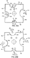
FIGS. 20A and 20B are side views of the dies ofFIG. 19 . -
FIGS. 21A and 21B are side views of the dies ofFIG. 19 being used with a threaded rod cutting machine. -
FIGS. 22A and22B are cross-sectional views of the dies ofFIG. 19 being used to cut a threaded rod in a threaded die cutting machine. -
FIGS. 23A and 23B are close-up perspective views of one set of threaded recesses of the dies ofFIG. 19 . -
FIGS. 24A and 24B are close-up perspective views of another set of threaded recesses of the dies ofFIG. 19 . - Example embodiments will now be described more fully with reference to the accompanying drawings. Example embodiments are provided so that this disclosure will be thorough, and will fully convey the scope to those who are skilled in the art. Numerous specific details are set forth such as examples of specific components, devices, and methods, to provide a thorough understanding of embodiments of the present disclosure. It will be apparent to those skilled in the art that specific details need not be employed, that example embodiments may be embodied in many different forms and that neither should be construed to limit the scope of the disclosure. In some example embodiments, well-known processes, well-known device structures, and well-known technologies are not described in detail.
- The terminology used herein is for the purpose of describing particular example embodiments only and is not intended to be limiting. As used herein, the singular forms "a," "an," and "the" may be intended to include the plural forms as well, unless the context clearly indicates otherwise. The terms "comprises," "comprising," "including," and "having," are inclusive and therefore specify the presence of stated features, steps, operations, elements, and/or components, but do not preclude the presence or addition of one or more other features, integers, steps, operations, elements, components, and/or groups thereof. The method steps, processes, and operations described herein are not to be construed as necessarily requiring their performance in the particular order discussed or illustrated, unless specifically identified as an order of performance. It is also to be understood that additional or alternative steps may be employed.
- When an element or layer is referred to as being "on," "engaged to," "connected to," or "coupled to" another element or layer, it may be directly on, engaged, connected or coupled to the other element or layer, or intervening elements or layers may be present. In contrast, when an element is referred to as being "directly on," "directly engaged to," "directly connected to," or "directly coupled to" another element or layer, there may be no intervening elements or layers present. Other words used to describe the relationship between elements should be interpreted in a like fashion (e.g., "between" versus "directly between," "adjacent" versus "directly adjacent," etc.). As used herein, the term "and/or" includes any and all combinations of one or more of the associated listed items.
- Although the terms first, second, third, etc. may be used herein to describe various elements, components, regions, layers and/or sections, these elements, components, regions, layers and/or sections should not be limited by these terms. These terms may be only used to distinguish one element, component, region, layer or section from another region, layer or section. Terms such as "first," "second," and other numerical terms when used herein do not imply a sequence or order unless clearly indicated by the context. Thus, a first element, component, region, layer or section discussed below could be termed a second element, component, region, layer or section without departing from the teachings of the example embodiments.
- Terms of degree such as "substantially," "approximately," and "about" may be used herein when describing the relative positions, sizes, dimensions, or values of various elements, components, regions, layers and/or sections. These terms mean that such relative positions, sizes, dimensions, or values are within the defined range or comparison (e.g., equal or close to equal) with sufficient precision as would be understood by one of ordinary skill in the art in the context of the various elements, components, regions, layers and/or sections being described.
- Referring to
FIGS. 1 and2 , a threadedrod cutting machine 10 comprises ahousing 12 with ahandle 14, atrigger 16 coupled to thehandle 12, and afront cover 16. Thehousing 12 contains amotor 24 and aspeed reduction transmission 30. Thecover 16 contains acam driving mechanism 60 that is coupled to the transmission 30 (as shown and described in more detail below). Exposed from thehousing 12 is a pair of cutting dies 18, 20 that are coupled to thecam driving mechanism 60. The cutting die 20 is fixed in position relative to thehousing 12, while the cutting die 18 is moveable relative to thehousing 12. The dies 18, 20 each include at least oneconcave recess rod 120 between the dies 18, 20. Actuation of thetrigger 14 causes themotor 24,transmission 30, andcam driving mechanism 60 to cause the moveable die 18 to move toward and past the fixed due 20 to cut the threadedrod 120 by a shearing action. - The motor 24 (which may be any type of motor such as an AC motor, a DC motor, a universal motor, a brushless motor, an air motor, or a combustion motor) is configured to be coupled to a power source (not shown). In the disclosed embodiment, the
housing 12 includes areceptacle 22 configured to receive a removable and rechargeable battery. However, it should be understood that the machine could additionally or alternatively be coupled to another source of electrical or non-electrical power (e.g., a built in battery, a non-rechargeable battery, an AC power source, a source of compressed air, a fuel cell, etc.). Themotor 24 is electrically connected to the electrical power source by aswitch 26, which is actuated by thetrigger 16 to control power delivery from the power source to themotor 24. Theswitch 26 may provide for constant or variable speed operation of themotor 24. - Referring also to
FIG. 3 themotor 24 includes a rotatable output shaft 28, which is drivingly coupled to thespeed reduction transmission 30. Thetransmission 30 has three stages that greatly reduce the speed and increase the torque from the output of themotor 24. Thefirst stage 32 comprises a planetary gear set 34 having aninput sun gear 36 fixed to the motor output shaft 28, a plurality of planet gears 38 that mesh with and orbit the sun gear, astationary ring gear 40 that surrounds and meshes with the planet gears 38, and anoutput carrier 42 to which the planet gears 38 are pinned. The output carrier is fixed to anintermediate shaft 43. Rotation of the motor output shaft 28 andsun gear 36 at a first speed causes the planet gears 38 to orbit thesun gear 36, which in turn causes output rotation of theplanet carrier 42 and theintermediate shaft 43 at a second speed, which is slower than the first speed of thesun gear 36. - The
second stage 44 includes a secondstage pinion gear 46 that is non-rotationally fixed to theintermediate shaft 43 so that it is driven at the same second rotational speed as the firststage output carrier 42. Theintermediate shaft 46 is supported at one end by abearing 47. The secondstage pinion gear 46 drivingly meshes with a much larger secondstage spur gear 48, with thepinion gear 46 andspur gear 48 having parallel axes. Rotation of the secondstage pinion gear 46 at the second speed drives the secondstage spur gear 48 to rotate at a third speed, which is slower than the second speed of the secondstage pinion gear 46. - The
third stage 50 includes a third stage pinion gear 52 non-rotationally fixed to the secondstage spur gear 48 so that it is driven at the same third rotational speed as the secondstage spur gear 48. The third stage pinion gear 52 drivingly meshes with a much larger thirdstage spur gear 54, with the pinion gear 52 andspur gear 54 having parallel axes. Rotation of the third stage pinion gear 52 at the third speed drives the thirdstage spur gear 54 at a fourth speed, which is slower than the third speed of the thirdstage pinion gear 42. - Referring also to
FIG. 4 , the thirdstage spur gear 54 is non-rotationally coupled to atransmission output shaft 56. Theoutput shaft 56 is transmits rotational power from thetransmission 30 to thecam driving mechanism 60 at the fourth rotational speed. The thirdstage spur gear 54 is coupled to thetransmission output shaft 56 by a key 58. The key 58 is configured to shear and interrupt power transmission to theoutput shaft 56 if the torque encountered by theoutput shaft 56 exceeds a predetermined threshold value. In other embodiments, theoutput shaft 56 may be coupled to the thirdstage spur gear 54 by other mechanisms, such as a plurality of keys that shear at high torque, by a plurality of splines, or by a press-fit. - Referring to
FIG. 5 , thecam driving mechanism 60 converts rotational motion of thetransmission output shaft 56 to the shearing motion of themovable die 18. Thecam driving mechanism 60 comprises aninput cam wheel 62 that is non-rotationally fixed to thetransmission output shaft 56 and that rotates about an input axis X in a first clockwise direction CW1. Theinput cam 62 includes a drivingflat surface 64, a drivingarc surface 66, and a returnflat surface 68. Also coupled to the input cam is aneccentric pin 70 that is mounted eccentrically relative to the input axis X. Theinput cam 62 abuts against anoutput cam follower 72. Theoutput cam roller 72 is configured to roll along thesurfaces input cam 62 as theinput cam 62 rotates about the input axis X. - The
output cam roller 72 is mounted to afirst end 76 of alever arm 74. The moveable die 18 is mounted to asecond end 78 of thelever arm 74 by a threaded bolt 75, which is inserted through a threaded bore in a rear face of the die 18 (FIG. 1 ). Thestationary die 20 is mounted to astationary arm 79 on thehousing 12 by a threaded bolt 77, which is inserted through a rear face of the die 20 (FIG. 2 ). Thelever arm 74 is mounted to thehousing 12 to pivot about afulcrum 80. When thelever arm 74 pivots in a second clockwise direction CW2 about thefulcrum 80, the moveable die 18 approaches and moves past thestationary die 20 in a shearing motion to cut the threadedrod 120. Thelever arm 74 is coupled to thetool housing 12 by atorsional return spring 82 that biases thesecond end 78 of thelever arm 74 and the moveable die 18 away from thestationary die 20 in a counterclockwise direction CCW about thefulcrum 80. Areturn plate 84 is fixedly mounted to thefirst end 76 of thelever arm 74. Thereturn plate 84 includes afirst opening 86 and asecond opening 88. Thesecond opening 88 is sized and configured so that theeccentric pin 70 follows an interior edge of thesecond opening 88 as theinput cam 62 rotates about the axis X. -
FIGS. 6A-6D illustrate the operation of thecam driving mechanism 60. Referring toFIG. 6A , at an initial open position, the moveable die 18 is fully open relative to thestationary die 20. A threadedrod 120 to be cut is placed in arecess 21 of thestationary die 20. Referring toFIG. 6B , during a driving stroke, rotation of themotor 24 is transmitted to theinput cam 62 through thetransmission 30. This causes theinput cam 62 to rotate in the first clockwise direction CW1 about the axis X. Theoutput cam roller 72 rolls along the driving flat 64 of theinput cam wheel 62, which in turn causes thelever arm 74 to pivot in the second clockwise direction CW2 about thefulcrum 80, bringing the moveable die 20 closer to thestationary die 18. Referring toFIG. 6C , during a power stoke, themotor 24, through thetransmission 30, causes theinput cam 62 to continue to rotate in the clockwise direction CW1 about the axis X. Thecam roller 72 rolls along the drivingarc surface 66 of theinput cam 62. This causes the lever arm to pivot further in the second clockwise direction CW2 about thefulcrum 80, causing the moveable die 18 to close around the threadedrod 120 and move past thestationary die 20, shearing the threadedrod 120. - Referring to
FIG. 6D , during a return stroke, theinput cam 62 continues to rotate in the first clockwise direction CW1 about the axis X, which causes thecam roller 72 to roll along the returnflat surface 68 of theinput cam wheel 62. Under the urging of thetorsional spring 82, this causes thelever arm 74 to pivot in the counterclockwise direction CCW about thefulcrum 80. This moves the moveable die 18 away from thestationary die 20 back toward the fully open position shown inFIG. 6A . If the moveable die 18 gets stuck in the closed position shown inFIG. 6C , theeccentric pin 70 also pushes against the interior edge of thesecond opening 88 in theplate 84, which assists thelever arm 74 to pivot in the counterclockwise direction CCW about thefulcrum 80. - Referring to
FIGS. 7-11 , in an embodiment, the dies 18 and 20 are identical and reversible so that the moveable die 18 can be installed as thestationary die 20 and vice versa. For convenience, only onesuch die 100 will be described in detail. Each die 100 has abody 101 with a generally polyhedral shape, e.g., a square or rectangular prismatic shape. Each die 100 has afront cutting face 102 and arear face 104 that are generally parallel to each other. A plurality of side faces 106a-106d (e.g., four side faces) extend between thefront face 102 and therear face 104, substantially perpendicular to thefront face 102 and to therear face 104. Each die 100 has cuttingedges 112a-112d at the edges defined by the junctions between the side faces 106a-106d and thefront cutting face 102. - Each of the side faces 106a-106d defines an
arcuate recess 114a-114d for receiving the threadedrod 120. Eacharcuate recess 114a-114d has a partially cylindrical shape (e.g., half of a cylinder) that extends from the cuttingface 102 to the rear face 140, and is threaded along its length by athread 116a-116d. The radius of eachrecess 114a-114d is sized to receive a threaded rod of a corresponding diameter, while the pitch and size of thethread 116a-116d is configured to correspond to a thread pitch and size on the threadedrod 120. In an embodiment, one or more of therecesses 114a-114d may have different sizes and/or thread pitches to accommodate different sized or configured threaded rods. Thus, the dies 100 can be rotated and mounted at different angular positions on thelever arrm 74 and stationary arm 79 (as described above) in order to cut a plurality of different sized threaded rods. In this manner, the dies 100 function to cut a variety of sizes of threaded rods. - Referring to
FIG. 11 , athread 116a on thedie 100 has athread crest 124 and athread trough 126 configured differently than athread crest 152 and thread tough 154 of the threadedrod 120, in order to make a cleaner cut in the threaded rod. For example, as shown schematically inFIG. 11 , thethread trough 126 of thethread 116a on thedie 100 may have a depth D1 (as measured from the thread crest 124) that is greater than a depth D2 of thethread trough 154 of thethread 150 of the threaded rod (as measured from the thread crest 152). The allows thethread crest 124 of the die 100 to engage thethread trough 154 of the threaded rod while preventing thethread trough 126 of the die 100 from engaging thethread crest 152 of the threaded rod. It is believed that this results in a cleaner cut to the threaded rod because the thread crests 124 of the cutting dies 100 concentrate the cutting forces at thethread roots 154 of the threadedrod 120, leaving the thread crests 152 of the threadedrod 120 less disturbed. - Referring to
FIG. 10 , each die 100 has a fastener receiver (e.g., a through bore 108) that is configured to be coupled to a fastener (e.g., mounting bolts 75, 77) on the threaded rod cutting machine. Thebore 108 extends through a center of thebody 101 from thefront face 102 to therear face 104 along a center axis A that is substantially perpendicular to thefront face 102 and to therear face 104. Thebore 108 is partially threaded by athread 110 that starts at therear face 104 but that terminates before reaching thefront face 102. Because of this partial thread, the threaded mounting bolts 75, 77 on thearms die 100, starting at therear face 104 of thedie 100. Thus, the dies 18, 20 can only be installed in the threaded cutting tool with their rear faces 104 facing theirrespective arms arms - Referring to
FIG. 7 andFIGS. 12A-12D , as discussed above, each of a pair of identical dies 100 may be installed in the position of thestationary die 20 and/or in the position of themoveable die 18. The side faces, cutting edges, and arcuate recesses that face each other are said to be the active side faces, cutting edges, and arcuate recesses. The dies 100 can be installed on thearms FIGS. 7 and12A-12D , theside face 106a, thecutting edge 112a and theannular recesses 114a of thedie 100 are active. However, it should be understood that any of the side faces, cutting edges and annular recesses of the cutting die 100 may be made active by rotating the die 100 about the threadedbore 108. To move thedie 100 between thestationary die position 20 and themoveable die position 18, thedie 100 can be rotated about a rotation axis B that is located along or parallel to the active cutting edge of thedie 100. In this example, thedie 100 can be rotated by an angle θ of approximately 180 degrees about the axis B between the position of thestationary die 20 and the position of themoveable die 18. - Referring to
FIGS. 7 and13A , to obtain a clean cut of a threaded rod, the front cutting faces 102 of the dies 18, 20 should substantially lie in a common cutting plane P so that the front cutting faces 102 do not overlap and are not substantially spaced apart. Referring also toFIGS. 14A-14C , in order to achieve this optimal positioning of the dies 18. 20 with their front cutting faces 102 substantially in a common plane P, the helical paths H traced by thethreads 116a of theactive recess 114a should be as close as possible to continuous as possible when the dies are closed about the threadedrod 120. In order to trace such a continuous helical path H, the starting points of thethreads 116a of theactive recesses 114a on the stationary die and the moveable die should substantially coincide or touch each other when the dies are closed around a threaded rod to be cut so that the path of the thread is continuous around the threaded rod. In particular, thethreads 116a of theactive recesses 114a on each of the dies each should have an actual or theoretical starting point that substantially coincides with a line L that bisects the threadedrod 120 when the dies are closed about the threadedrod 120. In this embodiment, the line L happens to coincide with the rotation axis B about which thedie 100 is rotated between the position of thestationary die 20 and the position of themoveable die 18. In addition, because theactive recess 114a is a half-cylinder, the line L also coincides with theactive cutting edge 112a of thedie 100. - In this example, the
thread crest 124 or thethread trough 126 of thedie 100 has an actual starting point that lies in the plane of thefront cutting face 102 along a circumference C of therecess 116a that intersects the line L. It should be noted that this means that there are twopossible starting points thread crest 126 or threadedtrough 126. In this embodiment, because thearcuate recess 112a is a half-cylinder, theactual starting points cutting edge 112a and in the plane of theactive side face 104a. In this embodiment, thethread crest 124 begins atstarting point 122A and thethread trough 126 begins atstarting point 122B. In alternative embodiments, only thethread trough 126 may begin atstarting point 122A orstarting point 122B, only thethread crest 124 may begin atstarting point 122A orstarting point 122B, or thethread crest 124 may begin atstarting point 122B and thethread trough 126 may begin atstarting point 122A. This also enables the die 100 to be reversibly attachable as either the moveable die 18 or thestationary die 20 because the starting points on the two dies will always substantially coincide. - Referring also to
FIGS. 13B and 13C , if the starting points of thethread crest 124 or thethread trough 126 are not positioned at theoptimal starting points threads 116a of theactive recesses 114a will not follow the desired continuous helical path H. For example, if thethread crest 124 has a starting point at 122C that is offset from theoptimal starting point 122A by approximately 45 degrees (as shown inFIG. 14B ), then, as shown inFIG. 13B , the helical paths H1 and H2 traced thethreads 116a of dies 18, 20 will be spaced apart by a distance d1. This will result in the cutting faces 102 of the dies 18, 20 being in planes P1 and P2 that are spaced apart by the distance d1, resulting in a poor cut to the threaded rod. In another example, if thethread crest 124 has a starting point at 122D that is offset from theoptimal starting point 122A by approximately 135 degrees (as shown inFIG. 14B ), then, as shown inFIG. 13C , the helical paths H3 and H4 traced thethreads 116a of dies 18, 20 will overlap by a distance d2. This will result in the cutting faces 102 of the dies 18, 20 being in planes P3 and P4 that overlap by the distance d2, resulting in the dies hitting each other upon cutting and resulting in a poor cut to the threaded rod. Thus, if thethreads 116a do not start at the optimal starting points, thedie 100 will not be reversibly attachable as either the moveable die 18 orstationary die 20 without adversely affecting the quality of the cut to the threaded rod. - Referring to
FIG. 16 , in another embodiment, adie 200 has a generally polyhedral body 201, afront cutting face 202, a rear face (not shown), and a plurality of side faces (not shown) extending between thefront face 202 and the rear face. Thedie 200 has cuttingedges 212a-212d at the edges defined by the junctions between the side faces and thefront cutting face 202. Each of the side faces defines anarcuate recess 214a-214d with athread 216a-216d for receiving the threadedrod 120. Unlike thedie 100, in thedie 200, thearcuate recesses 214a-214d each have a partially cylindrical shape that is less than half of a cylinder. Thus, the line L that bisects the threaded rod 120 (and the rotation axis B' about which thedie 200 is rotatable between the stationary die position and the moveable die position) are disposed a distance d3 away from theactive cutting edge 212a. - In order to achieve optimal positioning of the dies 200 with their front cutting faces 202 in substantially in a common plane, the thread crest or thread trough of the
thread 216a will have atheoretical starting point arcuate recess 214a that intersects the bisecting line L'. In the illustrated embodiment, the thread crest has atheoretical starting point 222A and the thread trough has a theoretical starting point 224B. It should be noted that anactual starting point 223A for the thread crest will be at a point where the adjacent thread crest intersects thefront cutting face 202, and anactual starting point 223B for the thread through will be at a point where the adjacent thread trough intersects thefront cutting face 202. In alternative embodiments, only the thread trough may begin at thetheoretical starting point 222A or thetheoretical starting point 222B, only the thread crest may begin at thetheoretical starting point 222A or thetheoretical starting point 222B, or the thread crest may begin at thetheoretical starting point 222B and the thread trough may begin at thetheoretical starting point 222A. In these alternative embodiments, the actual starting points will be at the point where the adjacent thread crest or thread trough intersects thefront cutting face 202. - Referring to
FIG. 16 , in an alternative embodiment, adie 300 may include abody 301 having afront cutting face 302, arear face 304, and a plurality of side faces 306a, 306c extending between thefront cutting face 302 and therear face 304. Each of the side faces 306a, 306c define a threadedannular recess central bore 308 extends through thebody 301. Thedie 300 differs from thedie 100 in that therear face 304 is transverse to thefront cutting face 302. Thus, thedie 300 has a non-prismatic polyhedral shape. - Referring to
FIGS. 17 and 18 , in two other alternative embodiments dies 400 and 500 each have abody front cutting face side face front cutting face arcuate recess rod 120. Each die 400, 500 has acutting edge front cutting face side face die 100 in that the side faces 406a, 506a and thecutting edges side face 406a and cuttingedge 412a ofdie 400 has a concave curvature, while theside face 506a and cuttingedge 512a of thedie 500 has a convex curvature. - Referring to
FIG. 19 , in another embodiment, a set of dies includes a firststationary die 600 and a secondmoveable die 650. Each die 600, 650 has abody front cutting face rear face 604, 654 that are generally parallel to each other. A plurality of side faces 606a-606d and 656a-656d (e.g., four side faces) extend between eachfront face rear face 604, 654, substantially perpendicular to thefront face rear face 604, 654. Each die 600, 656 has cuttingedges 612a-612d and 662a-662d at the edges defined by the junctions between the side faces 606a-606d, 656a-656d and eachfront cutting face moveable die 652 tends to be forced slightly away from thestationary die 602 in a direction X that is perpendicular to the plane P and parallel to the threaded rod so that the dies 602, 652 do not abut with and interfere with one another. - Each of the side faces 606a-606d and 652a-652d defines an
arcuate recess 614a-614d and 664a-664d for receiving a threaded rod. Eacharcuate recess 614a-614d and 664a-664d has a partially cylindrical shape (e.g., half of a cylinder) that extends from thefront face rear face 604, 654, and is threaded along its length by athread 616a-616d and 666a-666d. Eachthread 616a-616d and 666a-666d includes a series ofcrests 618a-618d and 668a-668d andtroughs 620a-620d and 670a-670d. The radius of eachrecess 614a-614d and 664a-664d is sized to receive a threaded rod of a corresponding diameter, while the pitch and size of thethread 616a-616d and 666a-666d is configured to correspond to a pitch and size of the thread on the threaded rod to be cut. In an embodiment, one or more of therecesses 614a-614d and 664a-664d may have different sizes and/or thread pitches to accommodate different sized or configured threaded rods. Thus, the dies 600, 650 can be rotated and mounted at different angular positions on thestationary arm 79 and thelever arm 74 in order to cut a plurality of different sized threaded rods, as described above. - Each die 600 also has a fastener receiver (e.g., a through
bore 608, 658) that is configured to be coupled to a fastener (e.g., mounting bolts 75, 77) on the threaded rod cutting machine. Eachbore body front face rear face 604, 654 along a center axis A, A' that is substantially perpendicular to thefront face rear face 604, 654. Eachbore thread 610, 660 that starts at therear face 604, 654 but that terminates before reaching thefront face arms rear face 604, 654 of each die 600, 650. Thus, the dies 600, 650 can only be installed in the threaded cutting tool with their rear faces 604, 654 facing theirrespective arms arms - Referring also to
FIGS. 20A and 20B , thefirst trough 620a-620d of eachthread 616a-616d of thestationary die 600 has astarting point 622a-622d where thefirst trough 620a-620d intersects a plane of thefront face 602. It should be noted that some of the starting points (e.g., 622d) may be theoretical starting points located away from the actualarcuate recess 614a-614d. Eachthread 616a-616d extends from thestarting point 622a-622d in a clockwise direction toward thecorresponding side face 606a-606d. Eachstarting point 622a-622d can be identified by an angle αA- αD measured relative to a radius Ra-Rd that bisects thecorresponding recess 614a-614d. Thefirst trough 670a-670d of eachthread 666a-666d of themoveable die 650 has astarting point 672a-672d where thefirst crest 668a-668d intersects a plane of thefront face 652. In the disclosed embodiment, the starting points are theoretical starting points located away from the actualarcuate recess 654a-654d, but that is not required. Eachthread 666a-666d extends from thestarting point 672a-672d in a clockwise direction toward thecorresponding side face 656a-656d. Eachstarting point 672a-672d can be identified by an angle βA- βD measured relative to measured relative to a radius Pa-Pd that bisects thecorresponding recess 614a-614d. - Referring also to
FIGS. 21A and22A , for each of the three smaller diameter (e.g., less than 1/2 inch) recesses 614a-614c and 654a-654c, thestarting points 622a-622c and 672a-672c of thethreads 616a-616c and 666a-666c are arranged so that the helical paths traced by thethreads 616a-616c of thestationary die 602 and thethreads 666a-666c of themoveable die 652 are as close as possible to continuous. In order to trace a continuous helical path, thestarting points 622a-622c of thesmaller diameter threads 616a-616c on thestationary die 602 are selected to almost coincide with thestarting points 672a-627c of thesmaller diameter threads 666a-666c on themoveable die 652 when themoveable die 652 has been inverted, coupled to thearm 74, and closed on the threaded rod. In one example, thestarting points 622a-622c of thesmaller diameter threads 616a-616c on thestationary die 602 are positioned at acute angles αA-αC (e.g., approximately 10°-30°) relative to a radius Ra-Rc that extends inward from theside face 606a-606c and bisects therecess 614a-614c, while thestarting points 672a-672c of thesmaller diameter threads 666a-666c on themoveable die 652 are positioned at acute angles βA-βC (e.g., approximately 30°-50°) relative to a radius Pa-Pc that extends outward from theside face 656a-656c and bisects therecess 654a-654c. When the dies 602, 652 are closed about a threadedrod 680, thecrests 618a-618c andtroughs 620a-620c of thesmaller diameter threads 616a-616c on thestationary die 602 and thecrests 668a-668c andtroughs 670a-670c of the threads all engage thecrests 684 andtroughs 686 of thethread 682 on the threadedrod 680. In addition, the thread depth D2, D3 of thethreads 616a-616c and 666a-666c is substantially the same as the thread depth D1 of the threadedrod 680. As the dies 602, 652 start to shear the threadedrod 680, themoveable die 652 is biased slightly away from the stationary die in a direction X parallel to the threadedrod 680 so that the dies 602, 652 do not interfere with one another during cutting. - Referring also to
FIGS. 21B and22B , when cutting larger diameter threaded rods (e.g., ½ inch and greater), the threaded rod cutting machine exerts a greater force biasing themoveable die 652 away from thestationary die 602 in the direction X along the threadedrod 680, resulting in poor cut quality with burrs on the cut surface. To counteract this biasing force, thestarting points threads thread 622d of thestationary die 602 and thethread 666d of themoveable die 652 are discontinuous. Thestarting point 622d of thelarger diameter thread 616d on thestationary die 602 is selected to not coincide with thestarting point 672d of thelarger diameter thread 666d on themoveable die 652. In one example, thestarting point 622d of thelarger diameter thread 616d on thestationary die 602 is positioned at an acute angle αD (e.g., approximately 45°-65°) relative to a radius Rd that extends outward from theside face 606d and bisects therecess 614d, while thestarting point 672d of thelarger diameter thread 666d on themoveable die 652 is positioned at an angle βD (e.g., approximately 45°-65°) relative to a radius Pd that extends outward from theside face 656d and bisects therecess 654d. The angles αD and βD may be (although are not required to be) approximately equal to each other so that the dies 602, 652 are reversible. When the dies 602, 652 are closed about a threadedrod 680, thecrests 618d andtroughs 620d of thelarger diameter thread 616d on thestationary die 602 engage thecrests 684 andtroughs 686 of thethread 682 on the threadedrod 680, but thecrests 668d and troughs 670d of thethread 666d on themoveable die 652 are offset from thecrests 684 andtroughs 686 of thethread 682 on the threadedrod 680 in a direction Y (opposite to direction X) parallel to the threadedrod 680. The offset distance d is less than the pitch p of thethread 682 of the threadedrod 608. This offset causes themoveable die 652 to be biased in the direction Y to counteract the biasing force exerted by the threaded rod cutting machine in the direction X, resulting in a cleaner cut. In addition, the thread depths D4, D5 of thethread 616d and thethread 666d are substantially the same as the thread depth D1 of the threadedrod 680. - A beneficial byproduct of making the threads of the moveable die offset from the threads on the threaded rod is that it enables the first thread on both dies to be thicker. As shown in
FIGS. 23A-23B , for thesmaller diameter recesses starting point 622a of thethread 616a on thestationary die 600 results in a very thinfirst thread 625a, while thestarting point 672a of thethread 666a on themoveable die 650 results in much thickerfirst thread 655a. The thinnerfirst thread 625a on thestationary die 600 is believed to contribute to reduced die life. However, it is not possible to have both first threads be thick and still have both dies be aligned with the threads on the threaded rod so that the helical paths traced by both threads are continuous. In contrast, as shown inFIGS. 24A-24B , for the larger diameter recesses 614d and 654d, thestarting points threads stationary die 600 and themoveable die 650 result in both dies having a relatively thickfirst thread 625d, 655d. This thicker first thread on both dies is achievable only because the moveable die is offset from the threads on the threaded rod and discontinuous from the thread on the stationary die. - Having thicker
first threads 625d, 655d on both dies results in a significant, and unexpected, increase in the life of both dies (especially the moveable die) as compared to dies that do not have thicker first threads on both dies. As shown in the below table, the number of cuts that can be performed using dies having a thicker first thread on both dies is dramatically greater than the number of cuts that can be performed using dies where only one die has a thicker first thread. The following table shows the results of nine samples of each set of dies, used to cut ½ inch threaded rod using the threaded rod cutting machine described above.Sample Single Die Has Thicker First Thread (# cuts) Both Dies Have Thicker First Thread (# cuts) 1 300 4250 2 520 4600 3 680 4850 4 700 3900 5 710 4400 6 750 7200 7 1180 7200 8 1780 8150 9 820 4900 Avg. 827 5294 - As shown in the above table, a design with both dies having a thicker first thread resulted in an increased die life, on average, of approximately 6.6 times as compared to a design with only a single die having a thicker first thread. This increase was a significant and unexpected byproduct of offsetting the moveable die to improve the cut quality.
- Numerous modifications may be made to the exemplary implementations described above. For example, the dies can have different shapes, such as having one or more faces and or edges being curved and/or non-parallel. In addition, the dies can have a different number or configuration of side faces (e.g., a hexagonal prism, a pentagonal prism, a triangular prism, a pyramid). The arcuate recesses in the dies may have the same or different sizes and thread pitches. These and other implementations are within the scope of the following claims.
Claims (16)
- A set of dies configured to be coupled to a machine for cutting threaded rods, the machine having a pair of arms each configured to hold one of the dies, at least one of the arms being moveable relative to the other arm to cause the dies to shear a threaded rod, the set of dies comprising:a first die having a first body with a first front face, a first rear face, a first side face extending between the first front face and the first rear face, and a first threaded arcuate recess with a first thread defined in the first side face and configured to receive a portion of a first threaded rod to be cut, wherein crests and troughs of the first thread are aligned with troughs and crests of a thread of the first threaded rod when the first die engages the first threaded rod; anda second die having a second body with a second front face, a second side face extending between the second front face and the second rear face, and a second threaded arcuate recess with a second thread defined in the second side face and configured to receive a portion of the first threaded rod to be cut, wherein crests and troughs of the second thread are axially offset from troughs and crests of the thread of the first threaded rod when the second die engages the first threaded rod.
- The set of dies of claim 1, wherein the first thread has a first trough starting point in a plane of the first front face and the second thread has a second trough starting point in a plane of the second front face, the first and second trough starting points located such that the first and second threads form a discontinuous helical path when the first and second dies are closed around the first threaded rod.
- The set of dies of claim 2, wherein the first trough starting point is spaced from the first die at a first acute angle in a counter-clockwise direction relative to a first radius that extends outward from the first side face and bisects the first recess, and the second starting point is located at a second acute angle in a counter-clockwise direction relative to a second recess that extends outward from the second side face and bisects the second recess.
- The set of dies of claim 3, wherein the first angle is approximately equal to the second angle so that the first die is interchangeable with the second die.
- The set of dies of claim 1, wherein
the first die further comprises a third side face extending between the first front face and the first rear face, and a third threaded arcuate recess with a third thread defined in the third side face and configured to receive a second threaded rod to be cut, wherein crests and troughs of the third thread are aligned with troughs and crests of a thread of the second threaded rod when the first die engages the second threaded rod; and
the second die further comprises a fourth side face extending between the second front face and the second rear face, and a fourth threaded arcuate recess with a fourth thread defined in the fourth side face and configured to receive the second threaded rod to be cut, wherein crests and troughs of the fourth thread are aligned with troughs and crests of the thread of the second threaded rod when the second die engages the second threaded rod. - The set of dies of claim 5, wherein the third thread has a third trough starting point in a plane of the third front face and the fourth thread has a fourth trough starting point in a plane of the second front face, the third and fourth trough starting points located such that the third and fourth threads form a continuous helical path when the first and second dies are closed around the second threaded rod.
- The set of dies of claim 6, wherein the third trough starting point is located at a third acute angle in a clockwise direction relative to a third radius that extends inward from the third side face and bisects the third recess, and the fourth starting point is located at a fourth acute angle in a counter-clockwise direction relative to a fourth radius that extends outward from the fourth side face and bisects the fourth recess.
- A set of dies configured to be coupled to a machine for cutting threaded rods, the machine having a pair of arms each configured to hold one of the dies, at least one of the arms being moveable relative to the other arm to cause the dies to shear a threaded rod, the set of dies comprising:a first die having a first body with a first front face, a first rear face, a first side face extending between the first front face and the first rear face, and a first threaded arcuate recess with a first thread defined in the first side face and configured to receive a portion of a first threaded rod to be cut; anda second die having a second body with a second front face, a second side face extending between the second front face and the second rear face, and a second threaded arcuate recess with a second thread defined in the second side face and configured to receive a portion of the first threaded rod to be cut,wherein the first and second threads are configured to form a discontinuous helical path when the first and second dies are closed around the first threaded rod..
- The set of dies of either of claims 1 or 8, wherein the second thread biases the second die toward the first die when cutting the first threaded rod, and preferably, the crests and troughs of the second thread biases the second die towards the first die when cutting the first threaded rod.
- The set of dies of claim 8, wherein the first thread has a first starting point in a plane of the first front face and the second thread has a second starting point in a plane of the second front face, the first and second starting points located such that the first and second threads form the discontinuous helical path when the first and second dies are closed around the first threaded rod.
- The set of dies of claim 10, wherein the first thread has a first trough starting point in a plane of the first front face and the second thread has a second trough starting point in a plane of the second front face, the first and second trough starting points located so that the first die is interchangeable with the second die.
- The set of dies of either of claims 4 or 11, wherein the first angle and the second angle are each approximately 50° to approximately 60°.
- The set of dies of either of claims 1 or 8, wherein the first die is configured to be stationary while cutting a threaded rod, and the second die is configured to be moveable while cutting a threaded rod.
- The set of dies of claim 8, wherein
the first die further comprises a third side face extending between the first front face and the first rear face, and a third threaded arcuate recess with a third thread defined in the third side face and configured to receive a second threaded rod to be cut,
the second die further comprises a fourth side face extending between the second front face and the second rear face, and a fourth threaded arcuate recess with a fourth thread defined in the fourth side face and configured to receive the second threaded rod to be cut, and
the third thread has a third starting point at the first front face and the fourth thread has a fourth starting point at the second front face, the third and fourth starting points located such that the third and fourth threads form a continuous helical path when the first and second dies are closed around the second threaded rod - The set of dies of claim 14 wherein crests and troughs of the third thread are aligned with troughs and crests of a thread of the second threaded rod when the first die engages the second threaded rod, and crests and troughs of the fourth thread are aligned with troughs and crests of the thread of the second threaded rod when the second die engages the second threaded rod.
- The set of dies of either of claims 5 or 14, wherein the second threaded rod, the third arcuate recess and the fourth arcuate recess each have a diameter less than a diameter of the first threaded rod, the first arcuate recess, and the second arcuate recess.
Applications Claiming Priority (1)
| Application Number | Priority Date | Filing Date | Title |
|---|---|---|---|
| US15/078,028 US10092966B2 (en) | 2014-10-10 | 2016-03-23 | Dies for threaded rod cutting machine |
Publications (2)
| Publication Number | Publication Date |
|---|---|
| EP3222379A1 true EP3222379A1 (en) | 2017-09-27 |
| EP3222379B1 EP3222379B1 (en) | 2021-12-15 |
Family
ID=58185346
Family Applications (1)
| Application Number | Title | Priority Date | Filing Date |
|---|---|---|---|
| EP17157956.8A Active EP3222379B1 (en) | 2016-03-23 | 2017-02-24 | Machine for cutting threaded rods |
Country Status (1)
| Country | Link |
|---|---|
| EP (1) | EP3222379B1 (en) |
Cited By (2)
| Publication number | Priority date | Publication date | Assignee | Title |
|---|---|---|---|---|
| US11548082B2 (en) | 2020-11-27 | 2023-01-10 | Milwaukee Electric Tool Corporation | Powered threaded rod cutter |
| EP4051447A4 (en) * | 2019-11-01 | 2024-04-03 | Milwaukee Electric Tool Corp | Portable pipe threader |
Citations (5)
| Publication number | Priority date | Publication date | Assignee | Title |
|---|---|---|---|---|
| JPS63127810A (en) * | 1986-11-14 | 1988-05-31 | Hitachi Koki Co Ltd | Cutting blade for bolt cutting-off machine |
| JPH01135410A (en) * | 1987-11-13 | 1989-05-29 | Hitachi Koki Co Ltd | Bolt cutting machine |
| JPH06297232A (en) | 1993-02-22 | 1994-10-25 | Hitachi Koki Co Ltd | Portable cutter |
| US5457889A (en) * | 1993-03-01 | 1995-10-17 | Kabushiki Kaisha Ogura | Jam-free shearing machine for threaded rods |
| US20160101477A1 (en) * | 2014-10-10 | 2016-04-14 | Black & Decker Inc. | Dies for threaded rod cutting machine |
-
2017
- 2017-02-24 EP EP17157956.8A patent/EP3222379B1/en active Active
Patent Citations (5)
| Publication number | Priority date | Publication date | Assignee | Title |
|---|---|---|---|---|
| JPS63127810A (en) * | 1986-11-14 | 1988-05-31 | Hitachi Koki Co Ltd | Cutting blade for bolt cutting-off machine |
| JPH01135410A (en) * | 1987-11-13 | 1989-05-29 | Hitachi Koki Co Ltd | Bolt cutting machine |
| JPH06297232A (en) | 1993-02-22 | 1994-10-25 | Hitachi Koki Co Ltd | Portable cutter |
| US5457889A (en) * | 1993-03-01 | 1995-10-17 | Kabushiki Kaisha Ogura | Jam-free shearing machine for threaded rods |
| US20160101477A1 (en) * | 2014-10-10 | 2016-04-14 | Black & Decker Inc. | Dies for threaded rod cutting machine |
Cited By (2)
| Publication number | Priority date | Publication date | Assignee | Title |
|---|---|---|---|---|
| EP4051447A4 (en) * | 2019-11-01 | 2024-04-03 | Milwaukee Electric Tool Corp | Portable pipe threader |
| US11548082B2 (en) | 2020-11-27 | 2023-01-10 | Milwaukee Electric Tool Corporation | Powered threaded rod cutter |
Also Published As
| Publication number | Publication date |
|---|---|
| EP3222379B1 (en) | 2021-12-15 |
Similar Documents
| Publication | Publication Date | Title |
|---|---|---|
| EP3006149A1 (en) | Dies for threaded rod cutting machine | |
| US10092966B2 (en) | Dies for threaded rod cutting machine | |
| EP1750880B1 (en) | A rotary to reciprocating motion conversion attachment for a power rotary hand tool | |
| US7743510B2 (en) | Powered tool for tube cutting and treating | |
| EP2036686B1 (en) | Saw with increased depth of cut | |
| US9724771B2 (en) | Reciprocating power tool | |
| US20140150271A1 (en) | Chain saw | |
| EP1491277B1 (en) | Reciprocating power tool | |
| EP3222379B1 (en) | Machine for cutting threaded rods | |
| DE112009005440B4 (en) | JIGSAW | |
| US20090194307A1 (en) | Torque limiting driver and method | |
| EP1732724B1 (en) | Apparatus for cutting an oval hole in the wall of a pipe | |
| WO1994017966A1 (en) | Wrist device of robot | |
| KR102132119B1 (en) | Top using crank arm refraction | |
| JPH072287B2 (en) | Handheld circular saw | |
| KR100893353B1 (en) | A powered tool for tube cutting and treating | |
| KR102519532B1 (en) | Saw system for vibration-free high place work | |
| RU128137U1 (en) | COMBINED TURNING CUTTER | |
| CN212250797U (en) | Eccentric distance adjustable centrifugal eccentric shaft | |
| CN220049704U (en) | Axial adjusting mechanism of roller shaft and roller press | |
| CN2522208Y (en) | Reciprocating sawing disc | |
| JP2006141212A (en) | Hedge trimmer | |
| JP2005069440A (en) | Gear structure | |
| KR20150073490A (en) | Apparatus for driving tilting axis gear of machine tool | |
| JPH02109669A (en) | Full automatic grinder for drill |
Legal Events
| Date | Code | Title | Description |
|---|---|---|---|
| PUAI | Public reference made under article 153(3) epc to a published international application that has entered the european phase |
Free format text: ORIGINAL CODE: 0009012 |
|
| STAA | Information on the status of an ep patent application or granted ep patent |
Free format text: STATUS: THE APPLICATION HAS BEEN PUBLISHED |
|
| AK | Designated contracting states |
Kind code of ref document: A1 Designated state(s): AL AT BE BG CH CY CZ DE DK EE ES FI FR GB GR HR HU IE IS IT LI LT LU LV MC MK MT NL NO PL PT RO RS SE SI SK SM TR |
|
| AX | Request for extension of the european patent |
Extension state: BA ME |
|
| STAA | Information on the status of an ep patent application or granted ep patent |
Free format text: STATUS: REQUEST FOR EXAMINATION WAS MADE |
|
| 17P | Request for examination filed |
Effective date: 20180322 |
|
| RBV | Designated contracting states (corrected) |
Designated state(s): AL AT BE BG CH CY CZ DE DK EE ES FI FR GB GR HR HU IE IS IT LI LT LU LV MC MK MT NL NO PL PT RO RS SE SI SK SM TR |
|
| GRAP | Despatch of communication of intention to grant a patent |
Free format text: ORIGINAL CODE: EPIDOSNIGR1 |
|
| STAA | Information on the status of an ep patent application or granted ep patent |
Free format text: STATUS: GRANT OF PATENT IS INTENDED |
|
| INTG | Intention to grant announced |
Effective date: 20210415 |
|
| GRAS | Grant fee paid |
Free format text: ORIGINAL CODE: EPIDOSNIGR3 |
|
| GRAJ | Information related to disapproval of communication of intention to grant by the applicant or resumption of examination proceedings by the epo deleted |
Free format text: ORIGINAL CODE: EPIDOSDIGR1 |
|
| GRAL | Information related to payment of fee for publishing/printing deleted |
Free format text: ORIGINAL CODE: EPIDOSDIGR3 |
|
| STAA | Information on the status of an ep patent application or granted ep patent |
Free format text: STATUS: REQUEST FOR EXAMINATION WAS MADE |
|
| INTC | Intention to grant announced (deleted) | ||
| GRAP | Despatch of communication of intention to grant a patent |
Free format text: ORIGINAL CODE: EPIDOSNIGR1 |
|
| STAA | Information on the status of an ep patent application or granted ep patent |
Free format text: STATUS: GRANT OF PATENT IS INTENDED |
|
| INTG | Intention to grant announced |
Effective date: 20210901 |
|
| GRAA | (expected) grant |
Free format text: ORIGINAL CODE: 0009210 |
|
| STAA | Information on the status of an ep patent application or granted ep patent |
Free format text: STATUS: THE PATENT HAS BEEN GRANTED |
|
| AK | Designated contracting states |
Kind code of ref document: B1 Designated state(s): AL AT BE BG CH CY CZ DE DK EE ES FI FR GB GR HR HU IE IS IT LI LT LU LV MC MK MT NL NO PL PT RO RS SE SI SK SM TR |
|
| REG | Reference to a national code |
Ref country code: GB Ref legal event code: FG4D Ref country code: CH Ref legal event code: EP |
|
| REG | Reference to a national code |
Ref country code: DE Ref legal event code: R096 Ref document number: 602017050826 Country of ref document: DE |
|
| REG | Reference to a national code |
Ref country code: IE Ref legal event code: FG4D |
|
| REG | Reference to a national code |
Ref country code: AT Ref legal event code: REF Ref document number: 1455111 Country of ref document: AT Kind code of ref document: T Effective date: 20220115 |
|
| REG | Reference to a national code |
Ref country code: LT Ref legal event code: MG9D |
|
| REG | Reference to a national code |
Ref country code: NL Ref legal event code: MP Effective date: 20211215 |
|
| PG25 | Lapsed in a contracting state [announced via postgrant information from national office to epo] |
Ref country code: RS Free format text: LAPSE BECAUSE OF FAILURE TO SUBMIT A TRANSLATION OF THE DESCRIPTION OR TO PAY THE FEE WITHIN THE PRESCRIBED TIME-LIMIT Effective date: 20211215 Ref country code: LT Free format text: LAPSE BECAUSE OF FAILURE TO SUBMIT A TRANSLATION OF THE DESCRIPTION OR TO PAY THE FEE WITHIN THE PRESCRIBED TIME-LIMIT Effective date: 20211215 Ref country code: FI Free format text: LAPSE BECAUSE OF FAILURE TO SUBMIT A TRANSLATION OF THE DESCRIPTION OR TO PAY THE FEE WITHIN THE PRESCRIBED TIME-LIMIT Effective date: 20211215 Ref country code: BG Free format text: LAPSE BECAUSE OF FAILURE TO SUBMIT A TRANSLATION OF THE DESCRIPTION OR TO PAY THE FEE WITHIN THE PRESCRIBED TIME-LIMIT Effective date: 20220315 |
|
| REG | Reference to a national code |
Ref country code: AT Ref legal event code: MK05 Ref document number: 1455111 Country of ref document: AT Kind code of ref document: T Effective date: 20211215 |
|
| PG25 | Lapsed in a contracting state [announced via postgrant information from national office to epo] |
Ref country code: SE Free format text: LAPSE BECAUSE OF FAILURE TO SUBMIT A TRANSLATION OF THE DESCRIPTION OR TO PAY THE FEE WITHIN THE PRESCRIBED TIME-LIMIT Effective date: 20211215 Ref country code: NO Free format text: LAPSE BECAUSE OF FAILURE TO SUBMIT A TRANSLATION OF THE DESCRIPTION OR TO PAY THE FEE WITHIN THE PRESCRIBED TIME-LIMIT Effective date: 20220315 Ref country code: LV Free format text: LAPSE BECAUSE OF FAILURE TO SUBMIT A TRANSLATION OF THE DESCRIPTION OR TO PAY THE FEE WITHIN THE PRESCRIBED TIME-LIMIT Effective date: 20211215 Ref country code: HR Free format text: LAPSE BECAUSE OF FAILURE TO SUBMIT A TRANSLATION OF THE DESCRIPTION OR TO PAY THE FEE WITHIN THE PRESCRIBED TIME-LIMIT Effective date: 20211215 Ref country code: GR Free format text: LAPSE BECAUSE OF FAILURE TO SUBMIT A TRANSLATION OF THE DESCRIPTION OR TO PAY THE FEE WITHIN THE PRESCRIBED TIME-LIMIT Effective date: 20220316 |
|
| PG25 | Lapsed in a contracting state [announced via postgrant information from national office to epo] |
Ref country code: NL Free format text: LAPSE BECAUSE OF FAILURE TO SUBMIT A TRANSLATION OF THE DESCRIPTION OR TO PAY THE FEE WITHIN THE PRESCRIBED TIME-LIMIT Effective date: 20211215 |
|
| PG25 | Lapsed in a contracting state [announced via postgrant information from national office to epo] |
Ref country code: SM Free format text: LAPSE BECAUSE OF FAILURE TO SUBMIT A TRANSLATION OF THE DESCRIPTION OR TO PAY THE FEE WITHIN THE PRESCRIBED TIME-LIMIT Effective date: 20211215 Ref country code: SK Free format text: LAPSE BECAUSE OF FAILURE TO SUBMIT A TRANSLATION OF THE DESCRIPTION OR TO PAY THE FEE WITHIN THE PRESCRIBED TIME-LIMIT Effective date: 20211215 Ref country code: RO Free format text: LAPSE BECAUSE OF FAILURE TO SUBMIT A TRANSLATION OF THE DESCRIPTION OR TO PAY THE FEE WITHIN THE PRESCRIBED TIME-LIMIT Effective date: 20211215 Ref country code: PT Free format text: LAPSE BECAUSE OF FAILURE TO SUBMIT A TRANSLATION OF THE DESCRIPTION OR TO PAY THE FEE WITHIN THE PRESCRIBED TIME-LIMIT Effective date: 20220418 Ref country code: ES Free format text: LAPSE BECAUSE OF FAILURE TO SUBMIT A TRANSLATION OF THE DESCRIPTION OR TO PAY THE FEE WITHIN THE PRESCRIBED TIME-LIMIT Effective date: 20211215 Ref country code: EE Free format text: LAPSE BECAUSE OF FAILURE TO SUBMIT A TRANSLATION OF THE DESCRIPTION OR TO PAY THE FEE WITHIN THE PRESCRIBED TIME-LIMIT Effective date: 20211215 Ref country code: CZ Free format text: LAPSE BECAUSE OF FAILURE TO SUBMIT A TRANSLATION OF THE DESCRIPTION OR TO PAY THE FEE WITHIN THE PRESCRIBED TIME-LIMIT Effective date: 20211215 |
|
| PG25 | Lapsed in a contracting state [announced via postgrant information from national office to epo] |
Ref country code: PL Free format text: LAPSE BECAUSE OF FAILURE TO SUBMIT A TRANSLATION OF THE DESCRIPTION OR TO PAY THE FEE WITHIN THE PRESCRIBED TIME-LIMIT Effective date: 20211215 Ref country code: AT Free format text: LAPSE BECAUSE OF FAILURE TO SUBMIT A TRANSLATION OF THE DESCRIPTION OR TO PAY THE FEE WITHIN THE PRESCRIBED TIME-LIMIT Effective date: 20211215 |
|
| REG | Reference to a national code |
Ref country code: DE Ref legal event code: R097 Ref document number: 602017050826 Country of ref document: DE |
|
| PG25 | Lapsed in a contracting state [announced via postgrant information from national office to epo] |
Ref country code: MC Free format text: LAPSE BECAUSE OF FAILURE TO SUBMIT A TRANSLATION OF THE DESCRIPTION OR TO PAY THE FEE WITHIN THE PRESCRIBED TIME-LIMIT Effective date: 20211215 Ref country code: IS Free format text: LAPSE BECAUSE OF FAILURE TO SUBMIT A TRANSLATION OF THE DESCRIPTION OR TO PAY THE FEE WITHIN THE PRESCRIBED TIME-LIMIT Effective date: 20220415 |
|
| REG | Reference to a national code |
Ref country code: CH Ref legal event code: PL |
|
| PLBE | No opposition filed within time limit |
Free format text: ORIGINAL CODE: 0009261 |
|
| STAA | Information on the status of an ep patent application or granted ep patent |
Free format text: STATUS: NO OPPOSITION FILED WITHIN TIME LIMIT |
|
| REG | Reference to a national code |
Ref country code: BE Ref legal event code: MM Effective date: 20220228 |
|
| PG25 | Lapsed in a contracting state [announced via postgrant information from national office to epo] |
Ref country code: LU Free format text: LAPSE BECAUSE OF NON-PAYMENT OF DUE FEES Effective date: 20220224 Ref country code: DK Free format text: LAPSE BECAUSE OF FAILURE TO SUBMIT A TRANSLATION OF THE DESCRIPTION OR TO PAY THE FEE WITHIN THE PRESCRIBED TIME-LIMIT Effective date: 20211215 Ref country code: AL Free format text: LAPSE BECAUSE OF FAILURE TO SUBMIT A TRANSLATION OF THE DESCRIPTION OR TO PAY THE FEE WITHIN THE PRESCRIBED TIME-LIMIT Effective date: 20211215 |
|
| 26N | No opposition filed |
Effective date: 20220916 |
|
| PG25 | Lapsed in a contracting state [announced via postgrant information from national office to epo] |
Ref country code: SI Free format text: LAPSE BECAUSE OF FAILURE TO SUBMIT A TRANSLATION OF THE DESCRIPTION OR TO PAY THE FEE WITHIN THE PRESCRIBED TIME-LIMIT Effective date: 20211215 |
|
| PG25 | Lapsed in a contracting state [announced via postgrant information from national office to epo] |
Ref country code: FR Free format text: LAPSE BECAUSE OF NON-PAYMENT OF DUE FEES Effective date: 20220228 |
|
| PG25 | Lapsed in a contracting state [announced via postgrant information from national office to epo] |
Ref country code: LI Free format text: LAPSE BECAUSE OF NON-PAYMENT OF DUE FEES Effective date: 20220228 Ref country code: IE Free format text: LAPSE BECAUSE OF NON-PAYMENT OF DUE FEES Effective date: 20220224 Ref country code: CH Free format text: LAPSE BECAUSE OF NON-PAYMENT OF DUE FEES Effective date: 20220228 |
|
| PG25 | Lapsed in a contracting state [announced via postgrant information from national office to epo] |
Ref country code: BE Free format text: LAPSE BECAUSE OF NON-PAYMENT OF DUE FEES Effective date: 20220228 |
|
| PG25 | Lapsed in a contracting state [announced via postgrant information from national office to epo] |
Ref country code: IT Free format text: LAPSE BECAUSE OF FAILURE TO SUBMIT A TRANSLATION OF THE DESCRIPTION OR TO PAY THE FEE WITHIN THE PRESCRIBED TIME-LIMIT Effective date: 20211215 |
|
| PGFP | Annual fee paid to national office [announced via postgrant information from national office to epo] |
Ref country code: GB Payment date: 20230105 Year of fee payment: 7 Ref country code: DE Payment date: 20221229 Year of fee payment: 7 |
|
| PG25 | Lapsed in a contracting state [announced via postgrant information from national office to epo] |
Ref country code: HU Free format text: LAPSE BECAUSE OF FAILURE TO SUBMIT A TRANSLATION OF THE DESCRIPTION OR TO PAY THE FEE WITHIN THE PRESCRIBED TIME-LIMIT; INVALID AB INITIO Effective date: 20170224 |