EP3222197A1 - Operation switching mechanism, endoscope - Google Patents
Operation switching mechanism, endoscope Download PDFInfo
- Publication number
- EP3222197A1 EP3222197A1 EP16761466.8A EP16761466A EP3222197A1 EP 3222197 A1 EP3222197 A1 EP 3222197A1 EP 16761466 A EP16761466 A EP 16761466A EP 3222197 A1 EP3222197 A1 EP 3222197A1
- Authority
- EP
- European Patent Office
- Prior art keywords
- biasing
- state
- reciprocating movement
- movement
- switching mechanism
- Prior art date
- Legal status (The legal status is an assumption and is not a legal conclusion. Google has not performed a legal analysis and makes no representation as to the accuracy of the status listed.)
- Withdrawn
Links
- 230000007246 mechanism Effects 0.000 title claims abstract description 112
- 230000003287 optical effect Effects 0.000 claims description 68
- 230000001629 suppression Effects 0.000 claims description 33
- 238000003780 insertion Methods 0.000 claims description 32
- 230000037431 insertion Effects 0.000 claims description 32
- 230000007704 transition Effects 0.000 claims description 28
- 230000008859 change Effects 0.000 claims description 3
- 238000005452 bending Methods 0.000 description 29
- 229910001285 shape-memory alloy Inorganic materials 0.000 description 10
- 238000010586 diagram Methods 0.000 description 6
- 230000004048 modification Effects 0.000 description 6
- 238000012986 modification Methods 0.000 description 6
- 230000006870 function Effects 0.000 description 5
- 230000009471 action Effects 0.000 description 4
- 230000000694 effects Effects 0.000 description 4
- 230000007257 malfunction Effects 0.000 description 4
- 230000009467 reduction Effects 0.000 description 3
- 230000005855 radiation Effects 0.000 description 2
- 230000003466 anti-cipated effect Effects 0.000 description 1
- 230000015572 biosynthetic process Effects 0.000 description 1
- 230000006835 compression Effects 0.000 description 1
- 238000007906 compression Methods 0.000 description 1
- 230000008602 contraction Effects 0.000 description 1
- 230000007797 corrosion Effects 0.000 description 1
- 238000005260 corrosion Methods 0.000 description 1
- 238000005286 illumination Methods 0.000 description 1
- 238000007689 inspection Methods 0.000 description 1
- 238000004519 manufacturing process Methods 0.000 description 1
- 210000000056 organ Anatomy 0.000 description 1
Images











Classifications
-
- G—PHYSICS
- G02—OPTICS
- G02B—OPTICAL ELEMENTS, SYSTEMS OR APPARATUS
- G02B23/00—Telescopes, e.g. binoculars; Periscopes; Instruments for viewing the inside of hollow bodies; Viewfinders; Optical aiming or sighting devices
- G02B23/24—Instruments or systems for viewing the inside of hollow bodies, e.g. fibrescopes
- G02B23/2407—Optical details
-
- A—HUMAN NECESSITIES
- A61—MEDICAL OR VETERINARY SCIENCE; HYGIENE
- A61B—DIAGNOSIS; SURGERY; IDENTIFICATION
- A61B1/00—Instruments for performing medical examinations of the interior of cavities or tubes of the body by visual or photographical inspection, e.g. endoscopes; Illuminating arrangements therefor
-
- A—HUMAN NECESSITIES
- A61—MEDICAL OR VETERINARY SCIENCE; HYGIENE
- A61B—DIAGNOSIS; SURGERY; IDENTIFICATION
- A61B1/00—Instruments for performing medical examinations of the interior of cavities or tubes of the body by visual or photographical inspection, e.g. endoscopes; Illuminating arrangements therefor
- A61B1/00002—Operational features of endoscopes
-
- A—HUMAN NECESSITIES
- A61—MEDICAL OR VETERINARY SCIENCE; HYGIENE
- A61B—DIAGNOSIS; SURGERY; IDENTIFICATION
- A61B1/00—Instruments for performing medical examinations of the interior of cavities or tubes of the body by visual or photographical inspection, e.g. endoscopes; Illuminating arrangements therefor
- A61B1/00163—Optical arrangements
-
- A—HUMAN NECESSITIES
- A61—MEDICAL OR VETERINARY SCIENCE; HYGIENE
- A61B—DIAGNOSIS; SURGERY; IDENTIFICATION
- A61B1/00—Instruments for performing medical examinations of the interior of cavities or tubes of the body by visual or photographical inspection, e.g. endoscopes; Illuminating arrangements therefor
- A61B1/00163—Optical arrangements
- A61B1/00188—Optical arrangements with focusing or zooming features
-
- A—HUMAN NECESSITIES
- A61—MEDICAL OR VETERINARY SCIENCE; HYGIENE
- A61B—DIAGNOSIS; SURGERY; IDENTIFICATION
- A61B1/00—Instruments for performing medical examinations of the interior of cavities or tubes of the body by visual or photographical inspection, e.g. endoscopes; Illuminating arrangements therefor
- A61B1/00163—Optical arrangements
- A61B1/00188—Optical arrangements with focusing or zooming features
- A61B1/0019—Optical arrangements with focusing or zooming features characterised by variable lenses
-
- A—HUMAN NECESSITIES
- A61—MEDICAL OR VETERINARY SCIENCE; HYGIENE
- A61B—DIAGNOSIS; SURGERY; IDENTIFICATION
- A61B1/00—Instruments for performing medical examinations of the interior of cavities or tubes of the body by visual or photographical inspection, e.g. endoscopes; Illuminating arrangements therefor
- A61B1/005—Flexible endoscopes
- A61B1/0051—Flexible endoscopes with controlled bending of insertion part
- A61B1/0052—Constructional details of control elements, e.g. handles
-
- G—PHYSICS
- G02—OPTICS
- G02B—OPTICAL ELEMENTS, SYSTEMS OR APPARATUS
- G02B23/00—Telescopes, e.g. binoculars; Periscopes; Instruments for viewing the inside of hollow bodies; Viewfinders; Optical aiming or sighting devices
- G02B23/24—Instruments or systems for viewing the inside of hollow bodies, e.g. fibrescopes
-
- G—PHYSICS
- G02—OPTICS
- G02B—OPTICAL ELEMENTS, SYSTEMS OR APPARATUS
- G02B23/00—Telescopes, e.g. binoculars; Periscopes; Instruments for viewing the inside of hollow bodies; Viewfinders; Optical aiming or sighting devices
- G02B23/24—Instruments or systems for viewing the inside of hollow bodies, e.g. fibrescopes
- G02B23/26—Instruments or systems for viewing the inside of hollow bodies, e.g. fibrescopes using light guides
-
- A—HUMAN NECESSITIES
- A61—MEDICAL OR VETERINARY SCIENCE; HYGIENE
- A61B—DIAGNOSIS; SURGERY; IDENTIFICATION
- A61B1/00—Instruments for performing medical examinations of the interior of cavities or tubes of the body by visual or photographical inspection, e.g. endoscopes; Illuminating arrangements therefor
- A61B1/00064—Constructional details of the endoscope body
-
- A—HUMAN NECESSITIES
- A61—MEDICAL OR VETERINARY SCIENCE; HYGIENE
- A61B—DIAGNOSIS; SURGERY; IDENTIFICATION
- A61B1/00—Instruments for performing medical examinations of the interior of cavities or tubes of the body by visual or photographical inspection, e.g. endoscopes; Illuminating arrangements therefor
- A61B1/00112—Connection or coupling means
- A61B1/00121—Connectors, fasteners and adapters, e.g. on the endoscope handle
Definitions
- the present invention relates to an operation switching mechanism and an endoscope including a long member that transmits a force for operating an operating section.
- endoscopes have been widely used in a medical field and an industrial field.
- the endoscope used in the medical field by inserting an elongated insertion section into a body cavity serving as a subject, it is possible to observe an organ in the body cavity with an optical system included in the insertion section and perform various kinds of treatment using, according to necessity, a treatment instrument inserted into an insert-through channel for the treatment instrument included in the endoscope.
- the endoscope used in the industrial field by inserting an elongated insertion section of the endoscope into an object such as a jet engine or a pipe in a factory, it is possible to perform observation and inspection of scratches, corrosions, and the like of a site to be examined in the object with an optical system included in the insertion section.
- a configuration is well known in which it is possible to change an observation magnification and a depth of field of a subject by reciprocatingly moving, using an operation switching mechanism, among optical members configuring an optical system provided in an insertion section of the endoscope, a zoom lens, which is an operating section, along an optical axis direction of the optical system.
- a configuration in which a known linear switch is used as the operation switching mechanism is well known.
- a shape memory alloy for expanding to bias a zoom-lens holding frame, which holds a zoom lens, forward in an optical axis direction in a non-energized state and contracting to move the zoom-lens holding frame backward in the optical axis direction in an energized state is connected to the zoom-lens holding frame, whereby the linear switch reciprocatingly moves the zoom lens in the optical axis direction to be capable of being switched to two positions of a forward position and a backward position using the expansion and contraction of the shape memory alloy.
- examples of the forward position include a normal observation position at an equal magnification in the optical system and examples of the backward position include a near point magnifying observation position for performing a magnifying observation in the optical system.
- the configuration in which the shape memory alloy is used in the operation switching mechanism has problems in that not only assembly cost increases because assembly is difficult but also manufacturing cost increases because the shape memory alloy is expensive and, besides, a failure risk increases because movement control of the zoom lens in which the shape memory alloy is used is complicated.
- Japanese Patent Application Laid-Open Publication No. 2000-221415 discloses a configuration of an operation switching mechanism in which a linear switch is used.
- the linear switch can reciprocatingly move a zoom lens frame, which holds a zoom lens in an insertion section of an endoscope, between a forward position and a backward position along a longitudinal direction of a wire substantially parallel to the optical axis direction and fix the zoom lens frame to be capable of being switched to the forward position and the backward position using two compression springs respectively wound in front and rear positions of the zoom lens frame around an outer circumference of a slide pin, which pierces through the zoom lens frame along an optical axis direction, and configured to respectively bias the zoom lens frame forward and backward in the optical axis direction and using the wire, which is a long member inserted through the insertion section of the endoscope, connected to the zoom lens frame, and towed and slacked using an operation member provided in an operation section of the endoscope.
- a position of the zoom lens can be fixed in, besides the forward position and the backward position, an intermediate position between the forward position and the backward position in the longitudinal direction. Therefore, it is likely that the zoom lens unintentionally moves along the longitudinal direction from the forward position and the backward position to between the forward position and the backward position because, for example, the wire moves in association with deformation of a bending section and a flexible tube section in the insertion section or, in bending operation of the bending section, the bending section interferes with a bending operation member and the wire moves.
- the present invention has been devised in view of the circumstances and an object of the present invention is to provide an operation switching mechanism and an endoscope that can realize, without a malfunction, surely and smoothly, and with a simple configuration, switching and fixing of an operating section to two positions involved in reciprocating movement of the operating section by a long member while achieving a reduction in size.
- An operation switching mechanism in an aspect of the present invention includes: a long member configured to transmit a force for operating an operating section; a reciprocating movement member to which the long member is connected, the reciprocating movement member reciprocatingly moving between a first movement position and a second movement position; a first biasing member configured to bias the reciprocating movement member toward the first movement position; a second biasing member configured to bias the reciprocating movement member toward the second movement position; a switching member configured to switch a state of the biasing by the first biasing member and the second biasing member such that the biasing by at least one of the first biasing member and the second biasing member is suppressed; and an operation member configured to operate the switching member according to operation from an outside and move the reciprocating movement member to the first movement position or the second movement position.
- An endoscope includes: an insertion section inserted into a subject; the operating section provided in the insertion section; and the operation switching mechanism configured to switch an operation state of the operating section.
- Fig. 1 is a perspective view showing an exterior of an endoscope including an operation switching mechanism of a first embodiment.
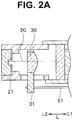
- Fig. 2A is a partial sectional view showing an optical system, which is provided in a distal end portion of an insertion section of the endoscope shown in Fig. 1 , together with a frame and a long member that hold the optical system.
- Fig. 2B is a partial sectional view showing a state in which an operating section shown in Fig. 2A moves forward in a longitudinal direction.
- Fig. 2C is a partial sectional view showing a state in which the operating section shown in Fig. 2A moves backward in the longitudinal direction.
- a main part of an endoscope 1 includes an insertion section 2 inserted into a subject, an operation section 3 concatenated on a proximal end side of the insertion section 2, a universal cord 8 extended from the operation section 3, and a connector 9 provided at an extension end of the universal cord 8.
- the endoscope 1 is electrically connected to external devices such as a control device and an illumination device via the connector 9.
- an up-down bending operation knob 4 configured to bend a bending section 2w explained below of the insertion section 2 in an up-down direction and a left-right bending operation knob 6 configured to bend the bending section 2w in a left-right direction are provided.
- a fixing lever 5 configured to fix a turning position of the up-down bending operation knob 4 and a fixing knob 7 configured to fix a turning position of the left-right bending operation knob 6 are provided.
- an operation switching mechanism 50 configured to switch an operation state of a zoom lens 30 explained below (see Fig. 2A ) is provided and a zoom lever 10 configured to operate the operation switching mechanism 50 and switch the operation state of the zoom lens 30 to thereby adjust optical characteristics of an optical system 20 explained below (see Fig. 2A ) is provided.
- the insertion section 2 includes a distal end portion 2s, the bending section 2w, and a flexible tube section 2k in order from a distal end side along a longitudinal direction L of a wire 51 explained below (see Fig. 2A ) substantially parallel to an optical axis direction of the optical system 20 explained below.
- the insertion section 2 is formed in an elongated shape.
- the bending section 2w is bent, for example, in upward, downward, left, and right four directions by turning operation of the up-down bending operation knob 4 and the left-right bending operation knob 6 to thereby change an observation direction of the optical system 20 explained below provided in the distal end portion 2s and improve insertability of the distal end portion 2s in the subject.
- the flexible tube section 2k is concatenated to a proximal end side of the bending section 2w.
- An optical system 20 configured to observe an inside of the subject is provided in the distal end portion 2s concatenated to the distal end side of the bending section 2w.
- the optical system 20 is configured from, for example, lenses, which are a plurality of optical members, and held in a lens frame 21.
- one optical member among the plurality of optical members configuring the optical system 20 configures a zoom lens 30, which is an operating section configured to reciprocatingly move along the longitudinal direction L to thereby adjust the optical characteristics of the optical system 20.
- the zoom lens 30 is held in a zoom lens frame 31.
- a distal end of a wire 51 which is a long member configured to transmit a force for operating the zoom lens 30, is connected to a part extended further to an outer side in a radial direction of the optical system 20 than the lens frame 21.
- the wire 51 reciprocatingly moves forward and backward in the longitudinal direction L, whereby the zoom lens 30 reciprocatingly moves forward and backward in the longitudinal direction L as shown in Fig. 2A and 2B via the zoom lens frame 31.
- the long member is not limited only to the wire 51 and only has to be a member that can transmit a force and a movement for reciprocating movement to the zoom lens 30, which is the operating section, from the operation switching mechanism 50 such as a filament that flexibly bends in a direction crossing the longitudinal direction L or a combination of the wire and the filament.
- the zoom lens 30 reciprocatingly moves between a forward position located forward in the longitudinal direction L and a backward position located backward in the longitudinal direction L.
- examples of the forward position include a normal observation position at an equal magnification in the optical system 20 and examples of the backward position include a near point magnifying observation position for performing a magnifying observation in the optical system 20.
- the wire 51 reciprocatingly moves the zoom lens 30 between the normal observation position and the near point magnifying observation position via the zoom lens frame 31 to thereby adjust the optical characteristics of the optical system 20.
- FIG. 3 is a plan view of the operation switching mechanism shown in Fig. 1 viewed from a III direction in Fig. 1 .
- Fig. 4 is a partial sectional view of the operation switching mechanism along a W1-W1 line in Fig. 3 in a third state of an operation member in the operation switching mechanism shown in Fig. 3 and a state in which a reciprocating movement member is located in a second movement position.
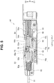
- Fig. 5 is a partial sectional view of the operation switching mechanism along a W2-W2 line in Fig. 3 in the third state of the operation member in the operation switching mechanism shown in Fig. 3 and the state in which the reciprocating movement member is located in the second movement position.
- Fig. 6 is a partial sectional view of the operation switching mechanism along the W1-W1 line in Fig. 3 in a first state of the operation member in the operation switching mechanism shown in Fig. 3 and the state in which the reciprocating movement member is located in the second movement position.
- Fig. 7 is a partial sectional view of the operation switching mechanism along the W2-W2 line in Fig. 3 in the first state of the operation member in the operation switching mechanism shown in Fig. 3 and the state in which the reciprocating movement member is located in the second movement position.
- Fig. 8 is a partial sectional view of the operation switching mechanism along the W1-W1 line in Fig. 3 in a second state of the operation member in the operation switching mechanism shown in Fig. 3 and a state in which the reciprocating movement member is located in a first movement position.
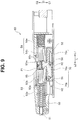
- Fig. 9 is a partial sectional view of the operation switching mechanism along the W2-W2 line in Fig. 3 in the second state of the operation member in the operation switching mechanism shown in Fig. 3 and the state in which the reciprocating movement member is located in the first movement position.
- Fig. 10 is a partial sectional view of the operation switching mechanism along the W1-W1 line in Fig. 3 in the first state of the operation member in the operation switching mechanism shown in Fig. 3 and the state in which the reciprocating movement member is located in the first movement position.
- Fig. 11 is a partial sectional view of the operation switching mechanism along the W2-W2 line in Fig. 3 in the first state of the operation member in the operation switching mechanism shown in Fig. 3 and the state in which the reciprocating movement member is located in the first movement position.
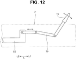
- Fig. 12 is a diagram schematically showing a mechanism configured to reciprocatingly move the operation member in the operation switching mechanism shown in Fig. 3 via the zoom lever 10 shown in Fig. 1 .
- a main part of the operation switching mechanism 50 includes an exterior housing 60, an operation member 52, a first biasing member 53, a second biasing member 54, a reciprocating movement member 55, a first switching member 57, and a second switching member 59 provided in the exterior housing 60, and the wire 51 extending from the exterior housing 60 to the insertion section 2 side serving as a front L2 side along the longitudinal direction L to an outside of the exterior housing 60.
- a distal end of the wire 51 is connected to the zoom lens frame 31.
- the wire 51 reciprocatingly moves to the front L2 side and a rear L1 side along the longitudinal direction L to thereby transmit a force for operating the zoom lens 30.
- the wire 51 is inserted through a biasing spring 53a explained below in the first biasing member 53.
- a proximal end of the wire 51 is connected to the reciprocating movement member 55 in the exterior housing 60.
- the reciprocating movement member 55 reciprocatingly moves in the longitudinal direction L between a second movement position P2 shown in Fig. 4 to Fig. 7 where the reciprocating movement member 55 is in contact with a positioning protrusion 60a of the exterior housing 60 and a first movement position P1 shown in Fig. 8 to Fig. 11 where the reciprocating movement member 55 is in contact with a positioning protrusion 60b of the exterior housing 60.
- the first movement position P1 is equivalent to a position switched to the backward position of the zoom lens 30 explained above, that is, the near point magnifying observation position of the optical system 20 as shown in Fig. 2C and the second movement position P2 is equivalent to a position switched to the forward position of the zoom lens 30 explained above, that is, the normal observation position of the optical system 20 as shown in Fig. 2B .
- a main part of the first biasing member 53 is configured from a biasing spring 53a configured from an elastic member, a distal end of the biasing spring 53a being supported in the exterior housing 60, and a pressing member 53b provided at a proximal end of the biasing spring 53a and including a spring section 53bs.
- the first biasing member 53 biases the reciprocating movement member 55 to the rear L1 side, which is one side in the longitudinal direction L, serving as the first movement position P1.
- the second biasing member 54 is located to be opposed to the first biasing member 53 in the longitudinal direction L.
- a main part of the second biasing member 54 is configured from a biasing spring 54a configured from an elastic member, a proximal end of the biasing spring 54a being supported in the exterior housing 60, and a pressing member 54b provided at a distal end of the biasing spring 54a and including a spring section 54bs.
- the second biasing member 54 biases the reciprocating movement member 55 to the front L2 side, which is the other side on an opposite side of the one side in the longitudinal direction L, serving as the second movement position P2.
- the first switching member 57 and the second switching member 59 perform operation for switching suppression of biasing by the first biasing member 53 and release of suppression of biasing by the second biasing member 54 and release of the suppression of the biasing by the first biasing member 53 and the suppression of the biasing by the second biasing member 54.
- the first switching member 57 and the second switching member 59 perform switching operation for, after performing the suppression of the biasing by the first biasing member 53 and the suppression of the biasing by the second biasing member 54, releasing the suppression of the biasing by the second biasing member 54 while keeping suppressing the biasing by the first biasing member 53 or releasing the suppression of the biasing by the first biasing member 53 while keeping suppressing the biasing by the second biasing member 54.
- first switching member 57 and the second switching member 59 are respectively operated, whereby states of the biasing by the first biasing member 53 and the second biasing member 54 are switched such that the biasing by at least one of the first biasing member 53 and the second biasing member 54 is suppressed.
- a main part of the first switching member 57 includes a protrusion 52a provided in the operation member 52 and a first moving member 56.
- an end portion of the spring section 53bs is brought into contact with the protrusion 52a in a first position H1 explained below of the first moving member 56, whereby the protrusion 52a suppresses the biasing by the first biasing member 53.
- an end portion of the first moving member 56 fits in a cam groove 70 in the operation member 52.
- the first moving member 56 reciprocatingly moves in a C1 direction and a C2 direction only in a direction C crossing the longitudinal direction L between a first position H1 for suppressing the biasing by the first biasing member 53 as shown in Fig. 5 , Fig. 7 , and Fig. 11 and a second position H2 for releasing the suppression of the biasing by the first biasing member 53 as shown in Fig. 9 .
- the first moving member 56 fits in a linear section 70a in the cam groove 70 in the first position H1 as shown in Fig. 5 , Fig. 7 , and Fig. 11 and fits in a key section 70b in the cam groove 70 in the second position H2 as shown in Fig. 9 .
- a main part of the second switching member 59 includes a protrusion 52b provided in the operation member 52 and a second moving member 58.
- an end portion of the second moving member 58 fits in the cam groove 70 in the operation member 52.
- the second moving member 58 reciprocatingly moves in the C1 direction and the C2 direction only in the direction C between a third position H3 for suppressing the biasing by the second biasing member 54 as shown in Fig. 7 , Fig. 9 , and Fig. 11 and a fourth position H4 for releasing the suppression of the biasing by the second biasing member 54 as shown in Fig. 5 .
- the second moving member 58 fits in the linear section 70a in the cam groove 70 in the third position H3 as shown in Fig. 7 , Fig. 9 , and Fig. 11 and fits in a key section 70c in the cam groove 70 in the fourth position H4 as shown in Fig. 5 .
- the operation member 52 operates the first switching member 57 and the second switching member 59 and moves the reciprocating movement member 55 to the first movement position P1 or the second movement position P2 according to operation from the outside.
- the operation member 52 is connected to the zoom lever 10 via a link mechanism 75.
- the operation member 52 is configured to be capable of reciprocatingly moving to the front L2 side and the rear L1 side in the longitudinal direction L via the link mechanism 75 according to turning of the zoom lever 10.
- the cam groove 70 including the linear section 70a having a predetermined length along the longitudinal direction L, the key section 70b bending from a distal end of the linear section 70a to the direction C2 side, and the key section 70c bending from a proximal end of the linear section 70a to the direction C2 side is formed. Further, a return member 52m located between the pressing member 53b and the pressing member 54b in the longitudinal direction L is formed.
- the operation member 52 moves the first moving member 56 between the first position H1 and the second position H2 in the direction C or moves the second moving member 58 between the third position H3 and the fourth position H4 in the direction C using the cam groove 70.
- the operation member 52 can be switched to, according to the reciprocating movement in the longitudinal direction L, any one state of a first state for disposing the first moving member 56 in the first position H1 and disposing the second moving member 58 in the third position as shown in Fig. 6 , Fig. 7 , Fig. 10 , and Fig. 11 to thereby locate the reciprocating movement member 55 in the first movement position P1 as shown in Fig. 10 and Fig. 11 or locate the reciprocating movement member 55 in the second movement position P2 as shown in Fig. 6 and Fig. 7 , a second state for disposing the first moving member 56 in the second position H2 and disposing the second moving member 58 in the third position H3 as shown in Fig. 8 and Fig.
- a not-shown resisting section configured to apply a resistance force against the reciprocating movement member 55 moving forward from the first movement position P1 along the longitudinal direction L with a force equal to or larger than the biasing force of the first biasing member 53 only has to be provided in at least one of the reciprocating movement member 55 or the wire 51.
- examples of the resisting section include a friction member provided in a passing section of the wire 51 in the insertion section 2 and configured to apply a frictional force to the wire 51 and a mechanism configured to apply a frictional force to the reciprocating movement member 55 when the first moving member 56 comes into contact with a bottom surface of the reciprocating movement member 55 and the like.
- a not-shown resisting section configured to apply a resistance force against the reciprocating movement member 55 moving backward from the second movement position P2 along the longitudinal direction L with a force equal to or larger than the biasing force of the second biasing member 54 only has to be provided in at least one of the reciprocating movement member 55 or the wire 51.
- examples of the resisting section include a friction member provided in the passing section of the wire 51 in the insertion section 2 and configured to apply a frictional force to the wire 51 and a mechanism configured to apply a frictional force to the reciprocating movement member 55 when the second moving member 58 comes into contact with a bottom surface of the reciprocating movement member 55 and the like.
- the return member 52m has a function of biasing the first biasing member 53 to the front L2 side and returning the first biasing member 53 to the first position H1 when the operation member 52 transitions from the second state shown in Fig. 8 and Fig. 9 to the first state shown in Fig. 10 and Fig. 11 and biasing the second biasing member 54 to the rear L1 side and returning the second biasing member 54 to the third position H3 when the operation member 52 transitions from the third state shown in Fig. 4 and Fig. 5 to the first state shown in Fig. 6 and Fig. 7 .
- the reciprocating movement member 55 when the reciprocating movement member 55 is located in the second movement position P2, which is the normal observation position of the zoom lens 30, as shown in Fig. 4 and Fig. 5 , as explained above, according to the biasing to the front L2 side by the second biasing member 54, the reciprocating movement member 55 is pressed against the positioning protrusion 60a with a biasing force. Therefore, the reciprocating movement member 55 less easily moves from the second movement position P2.
- the operation member 52 transitions from the third state shown in Fig. 4 and Fig. 5 in which the operation member 52 is located in the second movement position P2 to the second state shown in Fig. 8 and Fig. 9 in which the reciprocating movement member is located in the first movement position P1, which is the near point magnifying observation position of the zoom lens 30, the operation member 52 is moved to the rear L1 side from the states in Fig. 4 and Fig. 5 .
- the operation member 52 transitions from the third state shown in Fig. 4 and Fig. 5 to the first state shown in Fig. 6 and Fig. 7 .
- the second moving member 58 moves from the fourth position H4 to the third position H3, that is, fits in the linear section 70a from the key section 70c in the cam groove 70.
- the first moving member 56 stays in the first position H1.
- the return member 52m biases the second biasing member 54 to the rear L1 side and returns the second biasing member 54 to the third position H3.
- a state in which the second biasing member 54 biases the reciprocating movement member 55 to the front L2 side is released.
- the biasing is suppressed by the second switching member 59.
- the first biasing member 53 keeps a state in which the biasing is suppressed by the first switching member 57. Therefore, even if the operation member 52 transitions from the third state to the first state, the reciprocating movement member 55 remains located in the second movement position P2 as shown in Fig. 6 and Fig. 7 .
- the operation member 52 is moved further to the rear L1 side than in Fig. 6 and Fig. 7 to thereby transition from the first state shown in Fig. 6 and Fig. 7 to the second state shown in Fig. 8 and Fig. 9 .
- the first moving member 56 moves from the first position H1 to the second position H2, that is, fits in the key section 70b from the linear section 70a in the cam groove 70.
- the second moving member 58 stays in the third position H3.
- the first moving member 56 moves the spring section 53bs to the direction C2 side to a position where the spring section 53bs is not in contact with the protrusion 52a, whereby the first biasing member 53 biases the reciprocating movement member 55 to the rear L1 side.
- the reciprocating movement member 55 moves from the second movement position P2 to the first movement position P1 and is pressed against the positioning protrusion 60b with a biasing force by the first biasing member 53.
- the second biasing member 54 keeps the state in which the biasing is suppressed by the second switching member 59.
- the operation member 52 transitions from the third state to the second state.
- the zoom lens 30 moves backward via the reciprocating movement member 55, the wire 51, and the zoom lens frame 31 to thereby move from the normal observation position to the near point magnifying observation position.
- the reciprocating movement member 55 when the reciprocating movement member 55 is located in the first movement position P1, which is the near point magnifying observation position of the zoom lens 30, as shown in Fig. 8 and Fig. 9 , according to the biasing to the rear L1 side by the first biasing member 53, the reciprocating movement member 55 is pressed against the positioning protrusion 60b with a biasing force. Therefore, the reciprocating movement member 55 less easily moves from the first movement position P1.
- the operation member 52 transitions from the second state shown in Fig. 8 and Fig. 9 in which the operation member 52 is located in the first movement position P1 to the third state shown in Fig. 4 and Fig. 5 in which the reciprocating movement member is located in the second movement position P2, which is the normal observation position of the zoom lens 30, the operation member 52 is moved to the front L2 side from the states in Fig. 8 and Fig. 9 .
- the operation member 52 transitions from the second state shown in Fig. 8 and Fig. 9 to the first state shown in Fig. 10 and Fig. 11 .
- the first moving member 56 moves from the second position H2 to the first position H1, that is, fits in the linear section 70a from the key section 70b in the cam groove 70.
- the second moving member 58 stays in the third position H3.
- the return member 52m biases the first biasing member 53 to the front L2 side and returns the first biasing member 53 to the first position H1.
- a state in which the first biasing member 53 biases the reciprocating movement member 55 to the rear L1 side is released.
- the biasing is suppressed by the first switching member 57.
- the second biasing member 54 keeps a state in which the biasing is suppressed by the second switching member 59. Therefore, even if the operation member 52 transitions from the second state to the first state, the reciprocating movement member 55 is not biased by the biasing member 54 and remains located in the first movement position P1 as shown in Fig. 10 and Fig. 11 .
- the operation member 52 is moved further to the front L2 side than in Fig. 10 and Fig. 11 to thereby transition from the first state shown in Fig. 10 and Fig. 11 to the third state shown in Fig. 4 and Fig. 5 .
- the second moving member 58 moves from the third position H3 to the fourth position H4, that is, fits in the key section 70c from the linear section 70a in the cam groove 70.
- the first moving member 56 stays in the first position H1.
- the second moving member 58 moves the spring section 54bs to the direction C2 side to a position where the spring section 54bs is not in contact with the protrusion 52b, whereby the second biasing member 54 biases the reciprocating movement member 55 to the front L2 side.
- the reciprocating movement member 55 moves from the first movement position P1 to the second movement position P2 and is pressed against the positioning protrusion 60a with a biasing force by the second biasing member 54.
- the first biasing member 53 keeps the state in which the biasing is suppressed by the first switching member 57.
- the operation member 52 transitions from the second state to the third state.
- the zoom lens 30 moves forward via the reciprocating movement member 55, the wire 51, and the zoom lens frame 31 to thereby move from the near point magnifying observation position to the normal observation position.
- the zoom lens 30 it is possible to switch the zoom lens 30 to the two positions of the normal observation position and the near point magnifying observation position and fix positions of the zoom lens 30 in the respective positions using the simple and small operation switching mechanism 50 configured by the wire 51, the operation member 52, the biasing members 53 and 54, the reciprocating movement member 55, and the switching members 57 and 59 configured as explained above.
- the reciprocating movement member 55 is not stopped and fixed in a halfway position in the longitudinal direction L between the normal observation position and the near point magnifying observation position and reciprocatingly moves to be switched to only the two positions of the normal observation position and the near point magnifying observation position. Positions of the reciprocating movement member 55 can be more surely fixed by the biasing members 53 and 54 in the respective positions.
- the switching of the second state and the third state of the operation member 52 that is, the switching of the normal observation position and the near point magnifying observation position of the zoom lens 30 can be smoothly realized without a malfunction with a simple and small configuration in which the release of the suppression of the biasing by the first biasing member 53 involved in moving the first moving member 56 between the first position H1 and the second position H2 in the direction C using the cam groove 70 is used or the release of the suppression of the biasing by the second biasing member 54 involved in moving the second moving member 58 between the third position H3 and the fourth position H4 in the direction C using the cam groove 70 is used.
- the operation switching mechanism 50 in the present embodiment is configured from a linear switch including a simple mechanical configuration without using a shape memory alloy, a solenoid, or the like unlike in the past. Therefore, it is possible to realize the switching and movement of the two positions of the zoom lens 30 at low cost with a smaller configuration than in the past and without a malfunction.
- the operation switching mechanism 50 is provided in the operation section 3. Therefore, it is possible to further reduce the insertion section 2 in diameter than when the operation switching mechanism 50 is provided in the insertion section 2 as in the past.
- Fig. 13 is a partial sectional view of an operation switching mechanism schematically showing a third state of an operation member in the operation switching mechanism of a second embodiment and a state in which a reciprocating movement member is located in a second movement position.
- Fig. 14 is a partial sectional view of the operation switching mechanism schematically showing a first state of the operation member in the operation switching mechanism shown in Fig. 13 and the state in which the reciprocating movement member is located in the second movement position.
- Fig. 15 is a partial sectional view of the operation switching mechanism schematically showing a second state of the operation member in the operation switching mechanism shown in Fig. 14 and a state in which the reciprocating movement member is located in a first movement position.
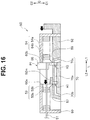
- Fig. 16 is a partial sectional view of the operation switching mechanism schematically showing the first state of the operation member in the operation switching mechanism shown in Fig. 15 and the state in which the reciprocating movement member is located in the first movement position.
- a configuration of the operation switching mechanism of the second embodiment is different from the configuration of the operation switching mechanism in the first embodiment shown in Fig. 1 to Fig. 12 in that each of switching members is configured from one member and a formation direction of a key section in a groove of the operation member. Therefore, components same as the components in the first embodiment are denoted by the same reference numerals and signs and explanation of the components is omitted.
- each of the first switching member 57 and the second switching member 59 is configured from one member fit in the cam groove 70. Therefore, the first switching member 57 functions as the first moving member 56 as well and the second switching member 59 functions as the second moving member 58 as well.
- the first switching member 57 and the second switching member 59 respectively come into contact with the pressing members 53b and 54b themselves in the first biasing member 53 and the second biasing member 54 to thereby suppress the biasing by the respective biasing members 53 and 54. Therefore, the pressing members 53b and 54b in the present embodiment do not respectively include the spring sections 53bs and 54bs.
- the cam groove 70 includes the linear section 70a having a predetermined length along the longitudinal direction L, the key section 70b bending from a distal end of the linear section 70a to the direction C1 side, and the key section 70c bending from a proximal end of the linear section 70a to the direction C1 side.
- the reciprocating movement member 55 shown in Fig. 13 when the reciprocating movement member 55 shown in Fig. 13 is located in the second movement position P2, which is the normal observation position of the zoom lens 30, as explained above, the first switching member 57 comes into contact with the pressing member 53b to suppress biasing by the first biasing member 53 and the second switching member 59 is not in contact with the pressing member 54b and releases suppression of biasing by the second biasing member 54. Therefore, according to the biasing to the front L2 side by the second biasing member 54, the reciprocating movement member 55 is pressed against the positioning protrusion 60a with a biasing force. The reciprocating movement member 55 less easily moves from the second movement position P2.
- the operation member 52 transitions from the third state in which the operation member 52 is located in the second movement position P2 to the second state shown in Fig. 15 in which the reciprocating movement member is located in the first movement position P1, which is the near point magnifying observation position of the zoom lens 30, the operation member 52 is moved to the rear L1 side from the state in Fig. 13 .
- the operation member 52 transitions from the third state shown in Fig. 13 to the first state shown in Fig. 14 .
- the second switching member 59 moves from the fourth position H4 to the third position H3, that is, fits in the linear section 70a from the key section 70c in the cam groove 70.
- the first switching member 57 stays in the first position H1.
- the return member 52m biases the second biasing member 54 to the first movement position P1, that is, the rear L1 side and returns the second biasing member 54 to the third position H3.
- a state in which the second biasing member 54 biases the reciprocating movement member 55 to the second movement position P2, that is, the front L2 side is released.
- the biasing is suppressed by the second switching member 59.
- the first biasing member 53 keeps a state in which the biasing is suppressed by the first switching member 57. Therefore, even if the operation member 52 transitions from the third state to the first state, the reciprocating movement member 55 remains located in the second movement position P2 as shown in Fig. 14 .
- the operation member 52 is moved further to the rear L1 side than in Fig. 14 to thereby transition from the first state shown in Fig. 14 to the second state shown in Fig. 15 .
- the first switching member 57 moves from the first position H1 to the second position H2, that is, fits in the key section 70b from the linear section 70a in the cam groove 70.
- the second switching member 59 stays in the third position H3.
- the reciprocating movement member 55 moves from the second movement position P2 to the first movement position P1 and is pressed against the positioning protrusion 60b with a biasing force by the first biasing member 53.
- the second biasing member 54 keeps the state in which the biasing is suppressed by the second switching member 59.
- the operation member 52 transitions from the third state to the second state.
- the zoom lens 30 moves backward via the reciprocating movement member 55, the wire 51, and the zoom lens frame 31 to thereby move from the normal observation position to the near point magnifying observation position.
- the second switching member 59 comes into contact with the pressing member 54b to thereby suppress the biasing by the second biasing member 54 and the first switching member 57 is not in contact with the pressing member 53b to release the suppression of the biasing by the first biasing member 53. Therefore, according to the biasing to the rear L1 side by the first biasing member 53, the reciprocating movement member 55 is pressed against the positioning protrusion 60b with a biasing force. Therefore, the reciprocating movement member 55 less easily moves from the first movement position P1.
- the operation member 52 transitions from the second state in which the operation member 52 is located in the first movement position P1 to the third state shown in Fig. 13 in which the reciprocating movement member is located in the second movement position P2, which is the normal observation position of the zoom lens 30, the operation member 52 is moved to the front L2 side from the state in Fig. 15 .
- the operation member 52 transitions from the second state shown in Fig. 15 to the first state shown in Fig. 16 .
- the first switching member 57 moves from the second position H2 to the first position H1, that is, fits in the linear section 70a from the key section 70b in the cam groove 70.
- the second switching member 59 stays in the third position H3.
- the return member 52m biases the first biasing member 53 to the front L2 side and returns the first biasing member 53 to the first position H1.
- a state in which the first biasing member 53 biases the reciprocating movement member 55 to the rear L1 side is released.
- the biasing is suppressed by the first switching member 57.
- the second biasing member 54 keeps a state in which the biasing is suppressed by the second switching member 59. Therefore, even if the operation member 52 transitions from the second state to the first state, the reciprocating movement member 55 remains located in the first movement position P1 as shown in Fig. 16 .
- the operation member 52 is moved further to the front L2 side than in Fig. 16 to thereby transition from the first state shown in Fig. 16 to the third state shown in Fig. 13 .
- the second switching member 59 moves from the third position H3 to the fourth position H4, that is, fits in the key section 70c from the linear section 70a in the cam groove 70.
- the first switching member 57 stays in the first position H1.
- the second switching member 59 releases the suppression of the biasing by the second biasing member 54, whereby the second biasing member 54 biases the reciprocating movement member 55 to the front L2 side. Therefore, the reciprocating movement member 55 moves from the first movement position P1 to the second movement position P2 and is pressed against the positioning protrusion 60a with a biasing force by the second biasing member 54. In this case, the first biasing member 53 keeps a state in which the biasing is suppressed by the first switching member 57.
- the operation member 52 transitions from the second state to the third state.
- the zoom lens 30 moves forward via the reciprocating movement member 55, the wire 51, and the zoom lens frame 31 to thereby move from the near point magnifying observation position to the normal observation position.
- Fig. 17 is a diagram schematically showing another configuration of the operation switching mechanism different from the configurations in Fig. 1 to Fig. 16 .
- Fig. 18 is a perspective view enlarging and showing a spiral-groove fitting member shown in Fig. 17 .
- Fig. 19 is a diagram of a fitting state of the cam and the operation member shown in Fig. 17 viewed from a XIX direction in Fig. 17 .
- a first biasing member 53' in an operation switching mechanism 50' may be configured from a torsion coil 53ac', a spiral-groove fitting member 53au' provided at one end of the torsion coil 53ac', a spiral bar 53ar' including a spiral groove M1 in which a protrusion T of the groove fitting member 53au' fits as shown in Fig. 18 , and a pressing member 53b'.
- a second biasing member 54' may be configured from a torsion coil 54ac', a spiral-groove fitting member 54au' provided at one end of the torsion coil 54ac', a spiral bar 54ar' including a spiral groove M2 in which a protrusion T of the groove fitting member 54au' fits as shown in Fig. 18 , and a pressing member 54b'.
- the protrusions T respectively move in the spiral grooves M1 and M2, whereby the respective biasing members 53' and 54' respectively bias the reciprocating movement member 55 to the first movement position P1, that is, the rear L1 side, and the second movement position P2, that is, the front L2 side, in the longitudinal direction L.
- a first switching member 57' may be configured from a stopper 57s' and a cam member 57c'.
- a second switching member 59' may be configured from a stopper 59s' and a cam member 59c'.
- the stopper 57s' is capable of turning around a turning axis 57sj'. Therefore, the stopper 57s' is capable of moving to the first position H1 and the second position H2 in the direction C.
- the stopper 57s' comes into contact with the pressing member 53b' in the first position H1 to thereby suppress biasing by the first biasing member 53'.
- the stopper 57s' is not in contact with the pressing member 53b' in the second position H2 to thereby release the suppression of the biasing by the first biasing member 53'.
- the stopper 59s' is capable of turning around a turning axis 59sj'. Therefore, the stopper 59s' is capable of moving to the third position H3 and the fourth position H4 in the direction C.
- the stopper 59s' comes into contact with the pressing member 54b' in the third position H3 to thereby suppress biasing by the second biasing member 54'.
- the stopper 59s' is not in contact with the pressing member 54b' in the fourth position H4 to thereby release the suppression of the biasing by the second biasing member 54'.
- the cam members 57c' and 59' are capable of turning around the respective turning axes 57cj' and 59cj'. As shown in Fig. 19 , the cam members 57c' and 59' include a groove R that fits with a convex rail 70' provided in the operation member 52'.
- the rail 70' includes a linear section 70a' having a predetermined length along the longitudinal direction L, a key section 70b' bending from a distal end of the linear section 70a' to the direction C2 side, and a key section 70c' bending from a proximal end of the linear section 70a to the direction C2 side.
- the cam member 57c' has a function of, in a state in which the groove R fits with the linear section 70a', being caught by the stopper 57s', fixing the stopper 57s' in the first position H1 where the stopper 57s' is in contact with the pressing member 53b', according to movement of the operation member 52' to the rear L1 side, fitting in the key section 70b' to thereby rotate clockwise, releasing locking of the stopper 57s', moving the stopper 57s' from the first position H1 to the second position H2, and, according to movement of the operation member 52' to the front L2 side, fitting in the linear section 70a' to thereby push up the stopper 57s' to be locked to the stopper 57s', and moving the stopper 57s' from the second position H2 to the first position H1.
- the cam member 59c' has a function of, in the state in which the groove R fits with the linear section 70a', being caught by the stopper 59s', fixing the stopper 59s' in the third position H3 where the stopper 59s' is in contact with the pressing member 54b', according to movement of the operation member 52' to the front L2 side, fitting in the key section 70c' to thereby rotate counterclockwise, releasing locking of the stopper 59s', moving the stopper 59s' from the third position H3 to the fourth position H4, and, according to movement of the operation member 52' to the rear L1 side, fitting in the linear section 70a' to thereby push up the stopper 59s' to be locked to the stopper 59s', and moving the stopper 59s' from the fourth position H4 to the third position H3.
- the first movement position P1 of the reciprocating movement member 55 is explained as being the proximity magnifying observation position and the second movement position P2 is explained as being the normal observation position.
- the first movement position P1 and the second movement position P2 are not limited thereto and naturally may be other positions of an optical system.
- the operating section is explained as being the zoom lens 30.
- the operation switching mechanism 50 is explained as performing the switching and fixing of the two positions of the zoom lens 30.
- the operation switching mechanism 50 is not limited to this and is also applicable in, as long as two values can be switched using a long member and positions of the two values can be fixed, a configuration for switching another operating section to two positions and moving the operation section, for example, a configuration for surely switching actually bending length of the bending section 2w provided in the insertion section 2 of the endoscope 1 to either one of two lengths and a configuration for switching, in a binary manner, a position of a filter that imparts an optical effect to various optical systems provided at the distal end portion 2s of the insertion section 2.
- the operation switching mechanism 50 is also applicable in, for example, a configuration for switching a bending length of the bending section 2w in two stages according to movement of the long member and a configuration for switching hardness of the flexible tube section 2k to two kinds of hardness according to the movement of the long member and the like.
- the switching member is configured from the two members, that is, the first switching member 57 and the second switching member 59.
- the switching member is not limited to this and may be configured from one member.
- the switching member only has to include, for example, a seesaw mechanism that swings around a fulcrum and switch the suppression of the biasing by the first biasing member 53 and the release of the suppression of the biasing by the second biasing member 54 and the release of the suppression of the biasing by the first biasing member 53 and the suppression of the biasing by the second biasing member 54.
- the respective embodiments may be used in a normal endoscope of a single screen type including one system of an optical system that observes an inside of a subject.
- Fig. 20 is a partial sectional view showing a modification in which the optical system shown in Fig. 2B is configured from two optical systems.
- Fig. 21 is a partial sectional view showing a modification in which the optical system shown in Fig. 2C is configured from two optical systems.
- the embodiments can also be used in a stereoscopic observation endoscope that performs three-dimensional observation by obtaining an image of an inside of a subject with a plurality of, for example, two optical systems.
- the plurality of, for example, two optical systems may be able to be switched by one operation switching mechanism.
- the respective optical systems may be able to be switched by individual operation switching mechanisms.
- Such an endoscope has an observation position suitable for three-dimensional observation. Therefore, the operation switching mechanisms of the respective embodiments may be used such that the endoscope can be appropriately switched to a necessary observation position suitable in performing the three-dimensional observation.
Landscapes
- Health & Medical Sciences (AREA)
- Life Sciences & Earth Sciences (AREA)
- Physics & Mathematics (AREA)
- Surgery (AREA)
- Optics & Photonics (AREA)
- Medical Informatics (AREA)
- Animal Behavior & Ethology (AREA)
- Radiology & Medical Imaging (AREA)
- Nuclear Medicine, Radiotherapy & Molecular Imaging (AREA)
- Engineering & Computer Science (AREA)
- Biomedical Technology (AREA)
- Heart & Thoracic Surgery (AREA)
- Biophysics (AREA)
- Molecular Biology (AREA)
- Pathology (AREA)
- General Health & Medical Sciences (AREA)
- Public Health (AREA)
- Veterinary Medicine (AREA)
- Astronomy & Astrophysics (AREA)
- General Physics & Mathematics (AREA)
- Instruments For Viewing The Inside Of Hollow Bodies (AREA)
- Endoscopes (AREA)
- Lens Barrels (AREA)
- Camera Bodies And Camera Details Or Accessories (AREA)
Abstract
Description
- The present invention relates to an operation switching mechanism and an endoscope including a long member that transmits a force for operating an operating section.
- In recent years, endoscopes have been widely used in a medical field and an industrial field. With the endoscope used in the medical field, by inserting an elongated insertion section into a body cavity serving as a subject, it is possible to observe an organ in the body cavity with an optical system included in the insertion section and perform various kinds of treatment using, according to necessity, a treatment instrument inserted into an insert-through channel for the treatment instrument included in the endoscope.
- With the endoscope used in the industrial field, by inserting an elongated insertion section of the endoscope into an object such as a jet engine or a pipe in a factory, it is possible to perform observation and inspection of scratches, corrosions, and the like of a site to be examined in the object with an optical system included in the insertion section.
- A configuration is well known in which it is possible to change an observation magnification and a depth of field of a subject by reciprocatingly moving, using an operation switching mechanism, among optical members configuring an optical system provided in an insertion section of the endoscope, a zoom lens, which is an operating section, along an optical axis direction of the optical system.
- More specifically, a configuration in which a known linear switch is used as the operation switching mechanism is well known. In the linear switch, a shape memory alloy for expanding to bias a zoom-lens holding frame, which holds a zoom lens, forward in an optical axis direction in a non-energized state and contracting to move the zoom-lens holding frame backward in the optical axis direction in an energized state is connected to the zoom-lens holding frame, whereby the linear switch reciprocatingly moves the zoom lens in the optical axis direction to be capable of being switched to two positions of a forward position and a backward position using the expansion and contraction of the shape memory alloy.
- Note that examples of the forward position include a normal observation position at an equal magnification in the optical system and examples of the backward position include a near point magnifying observation position for performing a magnifying observation in the optical system.
- However, the configuration in which the shape memory alloy is used in the operation switching mechanism has problems in that not only assembly cost increases because assembly is difficult but also manufacturing cost increases because the shape memory alloy is expensive and, besides, a failure risk increases because movement control of the zoom lens in which the shape memory alloy is used is complicated.
- When energization is performed to the shape memory alloy in order to contract the shape memory alloy, there are problems in that not only a heat radiation structure is separately necessary in the insertion section of the endoscope because the shape memory alloy generates heat but also a watertight structure for securing watertightness of the shape memory alloy is separately necessary in the insertion section.
- Note that a configuration is also well known in which the zoom lens is reciprocatingly moved along the optical axis direction to be capable of being switched to the two positions by an electromagnet in which a solenoid or the like is used. However, in the configuration, the heat radiation structure and the watertight structure are also separately necessary in the insertion section and, besides, a failure risk is high and, moreover, noise due to actuation of the electromagnet is sometimes mixed into an endoscopic observation image.
- In view of such problems, Japanese Patent Application Laid-Open Publication No.
2000-221415 - However, in the configuration described in Japanese Patent Application Laid-Open Publication No.
2000-221415 - In the configuration, a position of the zoom lens can be fixed in, besides the forward position and the backward position, an intermediate position between the forward position and the backward position in the longitudinal direction. Therefore, it is likely that the zoom lens unintentionally moves along the longitudinal direction from the forward position and the backward position to between the forward position and the backward position because, for example, the wire moves in association with deformation of a bending section and a flexible tube section in the insertion section or, in bending operation of the bending section, the bending section interferes with a bending operation member and the wire moves.
- In this case, in a configuration in which an optical system is set such that the optical system is focused only in the forward position and the backward position, which are switching positions of the linear switch, there is a problem in that the focus deviates in the intermediate position.
- Note that the problem of the deviation of the position of the operating section from the two positions occurs not only in the zoom lens but also in a configuration in which another operating section is switched and moved to the two positions with the operation switching mechanism in which the linear switch is used.
- That is, there is a demand for a configuration that can move, using the operation switching mechanism, the operating section to the two positions without stopping halfway between the two positions, that is, switch the operating section to the two positions.
- The present invention has been devised in view of the circumstances and an object of the present invention is to provide an operation switching mechanism and an endoscope that can realize, without a malfunction, surely and smoothly, and with a simple configuration, switching and fixing of an operating section to two positions involved in reciprocating movement of the operating section by a long member while achieving a reduction in size.
- An operation switching mechanism in an aspect of the present invention includes: a long member configured to transmit a force for operating an operating section; a reciprocating movement member to which the long member is connected, the reciprocating movement member reciprocatingly moving between a first movement position and a second movement position; a first biasing member configured to bias the reciprocating movement member toward the first movement position; a second biasing member configured to bias the reciprocating movement member toward the second movement position; a switching member configured to switch a state of the biasing by the first biasing member and the second biasing member such that the biasing by at least one of the first biasing member and the second biasing member is suppressed; and an operation member configured to operate the switching member according to operation from an outside and move the reciprocating movement member to the first movement position or the second movement position.
- An endoscope according to an aspect of the present invention includes: an insertion section inserted into a subject; the operating section provided in the insertion section; and the operation switching mechanism configured to switch an operation state of the operating section.
-
-
Fig. 1 is a perspective view showing an exterior of an endoscope including an operation switching mechanism of a first embodiment; -
Fig. 2A is a partial sectional view showing an optical system, which is provided in a distal end portion of an insertion section of the endoscope shown inFig. 1 , together with a frame and a long member that hold the optical system; -
Fig. 2B is a partial sectional view showing a state in which an operating section shown inFig. 2A moves forward in a longitudinal direction; -
Fig. 2C is a partial sectional view showing a state in which the operating section shown inFig. 2A moves backward in the longitudinal direction; -
Fig. 3 is a plan view of the operation switching mechanism shown inFig. 1 viewed from a III direction inFig. 1 ; -
Fig. 4 is a partial sectional view of the operation switching mechanism along a W1-W1 line inFig. 3 in a third state of an operation member in the operation switching mechanism shown inFig. 3 and a state in which a reciprocating movement member is located in a second movement position; -
Fig. 5 is a partial sectional view of the operation switching mechanism along a W2-W2 line inFig. 3 in the third state of the operation member in the operation switching mechanism shown inFig. 3 and the state in which the reciprocating movement member is located in the second movement position; -
Fig. 6 is a partial sectional view of the operation switching mechanism along the W1-W1 line inFig. 3 in a first state of the operation member in the operation switching mechanism shown inFig. 3 and the state in which the reciprocating movement member is located in the second movement position; -
Fig. 7 is a partial sectional view of the operation switching mechanism along the W2-W2 line inFig. 3 in the first state of the operation member in the operation switching mechanism shown inFig. 3 and the state in which the reciprocating movement member is located in the second movement position; -
Fig. 8 is a partial sectional view of the operation switching mechanism along the W1-W1 line inFig. 3 in a second state of the operation member in the operation switching mechanism shown inFig. 3 and a state in which the reciprocating movement member is located in a first movement position; -
Fig. 9 is a partial sectional view of the operation switching mechanism along the W2-W2 line inFig. 3 in the second state of the operation member in the operation switching mechanism shown inFig. 3 and the state in which the reciprocating movement member is located in the first movement position; -
Fig. 10 is a partial sectional view of the operation switching mechanism along the W1-W1 line inFig. 3 in the first state of the operation member in the operation switching mechanism shown inFig. 3 and the state in which the reciprocating movement member is located in the first movement position; -
Fig. 11 is a partial sectional view of the operation switching mechanism along the W2-W2 line inFig. 3 in the first state of the operation member in the operation switching mechanism shown inFig. 3 and the state in which the reciprocating movement member is located in the first movement position; -
Fig. 12 is a diagram schematically showing a mechanism configured to reciprocatingly move the operation member in the operation switching mechanism shown inFig. 3 via a zoom lever shown inFig. 1 ; -
Fig. 13 is a partial sectional view of an operation switching mechanism schematically showing a third state of an operation member in the operation switching mechanism of a second embodiment and a state in which a reciprocating movement member is located in a second movement position; -
Fig. 14 is a partial sectional view of the operation switching mechanism schematically showing a first state of the operation member in the operation switching mechanism shown inFig. 13 and the state in which the reciprocating movement member is located in the second movement position; -
Fig. 15 is a partial sectional view of the operation switching mechanism schematically showing a second state of the operation member in the operation switching mechanism shown inFig. 14 and a state in which the reciprocating movement member is located in a first movement position; -
Fig. 16 is a partial sectional view of the operation switching mechanism schematically showing the first state of the operation member in the operation switching mechanism shown inFig. 15 and the state in which the reciprocating movement member is located in the first movement position; -
Fig. 17 is a diagram schematically showing another configuration of the operation switching mechanism different from the configurations inFig. 1 to Fig. 16 ; -
Fig. 18 is a perspective view enlarging and showing a spiral-groove fitting member shown inFig. 17 ; -
Fig. 19 is a diagram of a fitting state of a cam and the operation member shown inFig. 17 viewed from a XIX direction inFig. 17 ; -
Fig. 20 is a partial sectional view showing a modification in which the optical system shown inFig. 2B is configured from two optical systems; and -
Fig. 21 is a partial sectional view showing a modification in which the optical system shown inFig. 2C is configured from two optical systems. - Embodiments of the present invention are explained below with reference to the drawings. Note that the drawings are schematic and relations between thicknesses and widths of respective members, ratios of the thicknesses of the respective members, and the like are different from real ones. It goes without saying that portions, relations and ratios of dimensions of which are different from one another, are included among the drawings.
-
Fig. 1 is a perspective view showing an exterior of an endoscope including an operation switching mechanism of a first embodiment.Fig. 2A is a partial sectional view showing an optical system, which is provided in a distal end portion of an insertion section of the endoscope shown inFig. 1 , together with a frame and a long member that hold the optical system.Fig. 2B is a partial sectional view showing a state in which an operating section shown inFig. 2A moves forward in a longitudinal direction.Fig. 2C is a partial sectional view showing a state in which the operating section shown inFig. 2A moves backward in the longitudinal direction. - As shown in
Fig. 1 , a main part of an endoscope 1 includes aninsertion section 2 inserted into a subject, anoperation section 3 concatenated on a proximal end side of theinsertion section 2, auniversal cord 8 extended from theoperation section 3, and a connector 9 provided at an extension end of theuniversal cord 8. Note that the endoscope 1 is electrically connected to external devices such as a control device and an illumination device via the connector 9. - In the
operation section 3, an up-downbending operation knob 4 configured to bend abending section 2w explained below of theinsertion section 2 in an up-down direction and a left-rightbending operation knob 6 configured to bend thebending section 2w in a left-right direction are provided. - In the
operation section 3, a fixinglever 5 configured to fix a turning position of the up-downbending operation knob 4 and a fixingknob 7 configured to fix a turning position of the left-rightbending operation knob 6 are provided. - Further, in the
operation section 3, anoperation switching mechanism 50 configured to switch an operation state of azoom lens 30 explained below (seeFig. 2A ) is provided and azoom lever 10 configured to operate theoperation switching mechanism 50 and switch the operation state of thezoom lens 30 to thereby adjust optical characteristics of anoptical system 20 explained below (seeFig. 2A ) is provided. - The
insertion section 2 includes adistal end portion 2s, thebending section 2w, and aflexible tube section 2k in order from a distal end side along a longitudinal direction L of awire 51 explained below (seeFig. 2A ) substantially parallel to an optical axis direction of theoptical system 20 explained below. Theinsertion section 2 is formed in an elongated shape. - The
bending section 2w is bent, for example, in upward, downward, left, and right four directions by turning operation of the up-downbending operation knob 4 and the left-rightbending operation knob 6 to thereby change an observation direction of theoptical system 20 explained below provided in thedistal end portion 2s and improve insertability of thedistal end portion 2s in the subject. Further, theflexible tube section 2k is concatenated to a proximal end side of thebending section 2w. - An
optical system 20 configured to observe an inside of the subject is provided in thedistal end portion 2s concatenated to the distal end side of thebending section 2w. - As shown in
Fig. 2A , theoptical system 20 is configured from, for example, lenses, which are a plurality of optical members, and held in alens frame 21. - Further, one optical member among the plurality of optical members configuring the
optical system 20 configures azoom lens 30, which is an operating section configured to reciprocatingly move along the longitudinal direction L to thereby adjust the optical characteristics of theoptical system 20. - The
zoom lens 30 is held in azoom lens frame 31. In thezoom lens frame 31, a distal end of awire 51, which is a long member configured to transmit a force for operating thezoom lens 30, is connected to a part extended further to an outer side in a radial direction of theoptical system 20 than thelens frame 21. - Therefore, the
wire 51 reciprocatingly moves forward and backward in the longitudinal direction L, whereby thezoom lens 30 reciprocatingly moves forward and backward in the longitudinal direction L as shown inFig. 2A and2B via thezoom lens frame 31. - Note that the long member is not limited only to the
wire 51 and only has to be a member that can transmit a force and a movement for reciprocating movement to thezoom lens 30, which is the operating section, from theoperation switching mechanism 50 such as a filament that flexibly bends in a direction crossing the longitudinal direction L or a combination of the wire and the filament. - More specifically, the
zoom lens 30 reciprocatingly moves between a forward position located forward in the longitudinal direction L and a backward position located backward in the longitudinal direction L. - Note that examples of the forward position include a normal observation position at an equal magnification in the
optical system 20 and examples of the backward position include a near point magnifying observation position for performing a magnifying observation in theoptical system 20. - That is, the
wire 51 reciprocatingly moves thezoom lens 30 between the normal observation position and the near point magnifying observation position via thezoom lens frame 31 to thereby adjust the optical characteristics of theoptical system 20. - A configuration of the
operation switching mechanism 50 provided in theoperation section 3 is explained with reference toFig. 3 to Fig. 12 .Fig. 3 is a plan view of the operation switching mechanism shown inFig. 1 viewed from a III direction inFig. 1 .Fig. 4 is a partial sectional view of the operation switching mechanism along a W1-W1 line inFig. 3 in a third state of an operation member in the operation switching mechanism shown inFig. 3 and a state in which a reciprocating movement member is located in a second movement position.Fig. 5 is a partial sectional view of the operation switching mechanism along a W2-W2 line inFig. 3 in the third state of the operation member in the operation switching mechanism shown inFig. 3 and the state in which the reciprocating movement member is located in the second movement position. -
Fig. 6 is a partial sectional view of the operation switching mechanism along the W1-W1 line inFig. 3 in a first state of the operation member in the operation switching mechanism shown inFig. 3 and the state in which the reciprocating movement member is located in the second movement position.Fig. 7 is a partial sectional view of the operation switching mechanism along the W2-W2 line inFig. 3 in the first state of the operation member in the operation switching mechanism shown inFig. 3 and the state in which the reciprocating movement member is located in the second movement position. - Further,
Fig. 8 is a partial sectional view of the operation switching mechanism along the W1-W1 line inFig. 3 in a second state of the operation member in the operation switching mechanism shown inFig. 3 and a state in which the reciprocating movement member is located in a first movement position.Fig. 9 is a partial sectional view of the operation switching mechanism along the W2-W2 line inFig. 3 in the second state of the operation member in the operation switching mechanism shown inFig. 3 and the state in which the reciprocating movement member is located in the first movement position. -
Fig. 10 is a partial sectional view of the operation switching mechanism along the W1-W1 line inFig. 3 in the first state of the operation member in the operation switching mechanism shown inFig. 3 and the state in which the reciprocating movement member is located in the first movement position.Fig. 11 is a partial sectional view of the operation switching mechanism along the W2-W2 line inFig. 3 in the first state of the operation member in the operation switching mechanism shown inFig. 3 and the state in which the reciprocating movement member is located in the first movement position. - Further,
Fig. 12 is a diagram schematically showing a mechanism configured to reciprocatingly move the operation member in the operation switching mechanism shown inFig. 3 via thezoom lever 10 shown inFig. 1 . - As shown in
Fig. 3 to Fig. 11 , a main part of theoperation switching mechanism 50 includes anexterior housing 60, anoperation member 52, a first biasingmember 53, asecond biasing member 54, areciprocating movement member 55, afirst switching member 57, and asecond switching member 59 provided in theexterior housing 60, and thewire 51 extending from theexterior housing 60 to theinsertion section 2 side serving as a front L2 side along the longitudinal direction L to an outside of theexterior housing 60. - As explained above, a distal end of the
wire 51 is connected to thezoom lens frame 31. Thewire 51 reciprocatingly moves to the front L2 side and a rear L1 side along the longitudinal direction L to thereby transmit a force for operating thezoom lens 30. Thewire 51 is inserted through a biasingspring 53a explained below in the first biasingmember 53. - A proximal end of the
wire 51 is connected to thereciprocating movement member 55 in theexterior housing 60. Thereciprocating movement member 55 reciprocatingly moves in the longitudinal direction L between a second movement position P2 shown inFig. 4 to Fig. 7 where thereciprocating movement member 55 is in contact with apositioning protrusion 60a of theexterior housing 60 and a first movement position P1 shown inFig. 8 to Fig. 11 where thereciprocating movement member 55 is in contact with apositioning protrusion 60b of theexterior housing 60. - Note that, when slight fluctuation of a stroke of sliding of the
wire 51 due to a shape state of theinsertion section 2 is anticipated, for example, the first movement position P1 is equivalent to a position switched to the backward position of thezoom lens 30 explained above, that is, the near point magnifying observation position of theoptical system 20 as shown inFig. 2C and the second movement position P2 is equivalent to a position switched to the forward position of thezoom lens 30 explained above, that is, the normal observation position of theoptical system 20 as shown inFig. 2B . - A main part of the first biasing
member 53 is configured from a biasingspring 53a configured from an elastic member, a distal end of the biasingspring 53a being supported in theexterior housing 60, and apressing member 53b provided at a proximal end of the biasingspring 53a and including a spring section 53bs. In theexterior housing 60, the first biasingmember 53 biases thereciprocating movement member 55 to the rear L1 side, which is one side in the longitudinal direction L, serving as the first movement position P1. - The
second biasing member 54 is located to be opposed to the first biasingmember 53 in the longitudinal direction L. A main part of the second biasingmember 54 is configured from a biasingspring 54a configured from an elastic member, a proximal end of the biasingspring 54a being supported in theexterior housing 60, and apressing member 54b provided at a distal end of the biasingspring 54a and including a spring section 54bs. In theexterior housing 60, the second biasingmember 54 biases thereciprocating movement member 55 to the front L2 side, which is the other side on an opposite side of the one side in the longitudinal direction L, serving as the second movement position P2. - The
first switching member 57 and thesecond switching member 59 perform operation for switching suppression of biasing by the first biasingmember 53 and release of suppression of biasing by the second biasingmember 54 and release of the suppression of the biasing by the first biasingmember 53 and the suppression of the biasing by the second biasingmember 54. - More specifically, the first switching
member 57 and thesecond switching member 59 perform switching operation for, after performing the suppression of the biasing by the first biasingmember 53 and the suppression of the biasing by the second biasingmember 54, releasing the suppression of the biasing by the second biasingmember 54 while keeping suppressing the biasing by the first biasingmember 53 or releasing the suppression of the biasing by the first biasingmember 53 while keeping suppressing the biasing by the second biasingmember 54. - That is, the first switching
member 57 and thesecond switching member 59 are respectively operated, whereby states of the biasing by the first biasingmember 53 and the second biasingmember 54 are switched such that the biasing by at least one of the first biasingmember 53 and the second biasingmember 54 is suppressed. - More specifically, a main part of the first switching
member 57 includes aprotrusion 52a provided in theoperation member 52 and a first movingmember 56. - As shown in
Fig. 4 ,Fig. 6 , andFig. 10 , an end portion of the spring section 53bs is brought into contact with theprotrusion 52a in a first position H1 explained below of the first movingmember 56, whereby theprotrusion 52a suppresses the biasing by the first biasingmember 53. - As shown in
Fig. 5 ,Fig. 7 ,Fig. 9 , andFig. 11 , an end portion of the first movingmember 56 fits in acam groove 70 in theoperation member 52. According to movement of theoperation member 52 to the front L2 side and the rear L1 side in the longitudinal direction L, in thecam groove 70, the first movingmember 56 reciprocatingly moves in a C1 direction and a C2 direction only in a direction C crossing the longitudinal direction L between a first position H1 for suppressing the biasing by the first biasingmember 53 as shown inFig. 5 ,Fig. 7 , andFig. 11 and a second position H2 for releasing the suppression of the biasing by the first biasingmember 53 as shown inFig. 9 . - Note that, the first moving
member 56 fits in alinear section 70a in thecam groove 70 in the first position H1 as shown inFig. 5 ,Fig. 7 , andFig. 11 and fits in akey section 70b in thecam groove 70 in the second position H2 as shown inFig. 9 . - A main part of the
second switching member 59 includes aprotrusion 52b provided in theoperation member 52 and a second movingmember 58. - As shown in
Fig. 6 ,Fig. 8 , andFig. 10 , in a third position H3 explained below of the second movingmember 58, a distal end of the spring section 54bs is brought into contact with theprotrusion 52b, whereby theprotrusion 52b suppresses the biasing by the second biasingmember 54. - As shown in
Fig. 5 ,Fig. 7 ,Fig. 9 , andFig. 11 , an end portion of the second movingmember 58 fits in thecam groove 70 in theoperation member 52. According to movement of theoperation member 52 to the front L2 side and the rear L1 side in the longitudinal direction L, in thecam groove 70, the second movingmember 58 reciprocatingly moves in the C1 direction and the C2 direction only in the direction C between a third position H3 for suppressing the biasing by the second biasingmember 54 as shown inFig. 7 ,Fig. 9 , andFig. 11 and a fourth position H4 for releasing the suppression of the biasing by the second biasingmember 54 as shown inFig. 5 . - The second moving
member 58 fits in thelinear section 70a in thecam groove 70 in the third position H3 as shown inFig. 7 ,Fig. 9 , andFig. 11 and fits in akey section 70c in thecam groove 70 in the fourth position H4 as shown inFig. 5 . - The
operation member 52 operates the first switchingmember 57 and thesecond switching member 59 and moves thereciprocating movement member 55 to the first movement position P1 or the second movement position P2 according to operation from the outside. - More specifically, as shown in
Fig. 12 , theoperation member 52 is connected to thezoom lever 10 via alink mechanism 75. Theoperation member 52 is configured to be capable of reciprocatingly moving to the front L2 side and the rear L1 side in the longitudinal direction L via thelink mechanism 75 according to turning of thezoom lever 10. - In the
operation member 52, besides theprotrusions Fig. 5 ,Fig. 7 ,Fig. 9 , andFig. 11 , thecam groove 70 including thelinear section 70a having a predetermined length along the longitudinal direction L, thekey section 70b bending from a distal end of thelinear section 70a to the direction C2 side, and thekey section 70c bending from a proximal end of thelinear section 70a to the direction C2 side is formed. Further, areturn member 52m located between thepressing member 53b and thepressing member 54b in the longitudinal direction L is formed. - The
operation member 52 moves the first movingmember 56 between the first position H1 and the second position H2 in the direction C or moves the second movingmember 58 between the third position H3 and the fourth position H4 in the direction C using thecam groove 70. - More specifically, the
operation member 52 can be switched to, according to the reciprocating movement in the longitudinal direction L, any one state of a first state for disposing the first movingmember 56 in the first position H1 and disposing the second movingmember 58 in the third position as shown inFig. 6 ,Fig. 7 ,Fig. 10 , andFig. 11 to thereby locate thereciprocating movement member 55 in the first movement position P1 as shown inFig. 10 andFig. 11 or locate thereciprocating movement member 55 in the second movement position P2 as shown inFig. 6 andFig. 7 , a second state for disposing the first movingmember 56 in the second position H2 and disposing the second movingmember 58 in the third position H3 as shown inFig. 8 andFig. 9 to locate thereciprocating movement member 55 in the first movement position P1 according to biasing to the rear L1 side by the first biasingmember 53, and a third state for disposing the first movingmember 56 in the first position H1 and disposing the second movingmember 58 in the fourth position H4 as shown inFig. 4 andFig. 5 to thereby locate thereciprocating movement member 55 in the second movement position P2 according to biasing to the front L2 side by the second biasingmember 54. - Note that, in the second state shown in
Fig. 8 andFig. 9 , according to the biasing to the rear L1 side by the first biasingmember 53, thereciprocating movement member 55 is pressed against thepositioning protrusion 60b with a biasing force. Therefore, thereciprocating movement member 55 less easily moves from the first movement position P1. - Therefore, if a force equal to or larger than the biasing force of the first biasing
member 53 is applied to the front L2 side, it is likely that thereciprocating movement member 55 moves to the front L2 side. In this case, a not-shown resisting section configured to apply a resistance force against thereciprocating movement member 55 moving forward from the first movement position P1 along the longitudinal direction L with a force equal to or larger than the biasing force of the first biasingmember 53 only has to be provided in at least one of thereciprocating movement member 55 or thewire 51. - Note that examples of the resisting section include a friction member provided in a passing section of the
wire 51 in theinsertion section 2 and configured to apply a frictional force to thewire 51 and a mechanism configured to apply a frictional force to thereciprocating movement member 55 when the first movingmember 56 comes into contact with a bottom surface of thereciprocating movement member 55 and the like. - In the third state shown in
Fig. 4 andFig. 5 , thereciprocating movement member 55 is pressed against thepositioning protrusion 60a with a biasing force according to the biasing to the front L2 side by the second biasingmember 54. Therefore, thereciprocating movement member 55 less easily moves from the second movement position P2. - Therefore, if a force equal to or larger than the biasing force of the second biasing
member 54 is applied to the rear L1 side, it is likely that thereciprocating movement member 55 moves to the rear L1 side. In this case, a not-shown resisting section configured to apply a resistance force against thereciprocating movement member 55 moving backward from the second movement position P2 along the longitudinal direction L with a force equal to or larger than the biasing force of the second biasingmember 54 only has to be provided in at least one of thereciprocating movement member 55 or thewire 51. - Note that examples of the resisting section include a friction member provided in the passing section of the
wire 51 in theinsertion section 2 and configured to apply a frictional force to thewire 51 and a mechanism configured to apply a frictional force to thereciprocating movement member 55 when the second movingmember 58 comes into contact with a bottom surface of thereciprocating movement member 55 and the like. - The
return member 52m has a function of biasing the first biasingmember 53 to the front L2 side and returning the first biasingmember 53 to the first position H1 when theoperation member 52 transitions from the second state shown inFig. 8 andFig. 9 to the first state shown inFig. 10 andFig. 11 and biasing the second biasingmember 54 to the rear L1 side and returning the second biasingmember 54 to the third position H3 when theoperation member 52 transitions from the third state shown inFig. 4 andFig. 5 to the first state shown inFig. 6 andFig. 7 . - Action of the
operation switching mechanism 50 in the present embodiment configured in this way is explained. - First, in the
operation member 52, when thereciprocating movement member 55 is located in the second movement position P2, which is the normal observation position of thezoom lens 30, as shown inFig. 4 andFig. 5 , as explained above, according to the biasing to the front L2 side by the second biasingmember 54, thereciprocating movement member 55 is pressed against thepositioning protrusion 60a with a biasing force. Therefore, thereciprocating movement member 55 less easily moves from the second movement position P2. - Thereafter, when the
operation member 52 transitions from the third state shown inFig. 4 andFig. 5 in which theoperation member 52 is located in the second movement position P2 to the second state shown inFig. 8 andFig. 9 in which the reciprocating movement member is located in the first movement position P1, which is the near point magnifying observation position of thezoom lens 30, theoperation member 52 is moved to the rear L1 side from the states inFig. 4 andFig. 5 . First, theoperation member 52 transitions from the third state shown inFig. 4 andFig. 5 to the first state shown inFig. 6 andFig. 7 . - At this point, as shown in
Fig. 5 andFig. 7 , the second movingmember 58 moves from the fourth position H4 to the third position H3, that is, fits in thelinear section 70a from thekey section 70c in thecam groove 70. The first movingmember 56 stays in the first position H1. - The
return member 52m biases the second biasingmember 54 to the rear L1 side and returns the second biasingmember 54 to the third position H3. As a result, as shown inFig. 6 andFig. 7 , a state in which the second biasingmember 54 biases thereciprocating movement member 55 to the front L2 side is released. The biasing is suppressed by thesecond switching member 59. - The
first biasing member 53 keeps a state in which the biasing is suppressed by the first switchingmember 57. Therefore, even if theoperation member 52 transitions from the third state to the first state, thereciprocating movement member 55 remains located in the second movement position P2 as shown inFig. 6 andFig. 7 . - Thereafter, the
operation member 52 is moved further to the rear L1 side than inFig. 6 andFig. 7 to thereby transition from the first state shown inFig. 6 andFig. 7 to the second state shown inFig. 8 andFig. 9 . - At this point, as shown in
Fig. 7 andFig. 9 , the first movingmember 56 moves from the first position H1 to the second position H2, that is, fits in thekey section 70b from thelinear section 70a in thecam groove 70. The second movingmember 58 stays in the third position H3. - As a result, according to the fitting of the first moving
member 56 in thekey section 70b bending to the direction C2 side, as shown inFig. 8 andFig. 9 , the first movingmember 56 moves the spring section 53bs to the direction C2 side to a position where the spring section 53bs is not in contact with theprotrusion 52a, whereby the first biasingmember 53 biases thereciprocating movement member 55 to the rear L1 side. - Therefore, the
reciprocating movement member 55 moves from the second movement position P2 to the first movement position P1 and is pressed against thepositioning protrusion 60b with a biasing force by the first biasingmember 53. In this case, the second biasingmember 54 keeps the state in which the biasing is suppressed by thesecond switching member 59. - Consequently, the
operation member 52 transitions from the third state to the second state. Thezoom lens 30 moves backward via thereciprocating movement member 55, thewire 51, and thezoom lens frame 31 to thereby move from the normal observation position to the near point magnifying observation position. - Contact sound of the
reciprocating movement member 55 coming into contact with thepositioning protrusion 60b or release sound of the biasingspring 54a released from a contracted state occurs. Therefore, an operator can easily recognize that thezoom lens 30 moves from the normal observation position to the near point magnifying observation position. - In the
operation member 52, when thereciprocating movement member 55 is located in the first movement position P1, which is the near point magnifying observation position of thezoom lens 30, as shown inFig. 8 andFig. 9 , according to the biasing to the rear L1 side by the first biasingmember 53, thereciprocating movement member 55 is pressed against thepositioning protrusion 60b with a biasing force. Therefore, thereciprocating movement member 55 less easily moves from the first movement position P1. - Thereafter, when the
operation member 52 transitions from the second state shown inFig. 8 andFig. 9 in which theoperation member 52 is located in the first movement position P1 to the third state shown inFig. 4 andFig. 5 in which the reciprocating movement member is located in the second movement position P2, which is the normal observation position of thezoom lens 30, theoperation member 52 is moved to the front L2 side from the states inFig. 8 andFig. 9 . First, theoperation member 52 transitions from the second state shown inFig. 8 andFig. 9 to the first state shown inFig. 10 andFig. 11 . - At this point, as shown in
Fig. 9 andFig. 11 , the first movingmember 56 moves from the second position H2 to the first position H1, that is, fits in thelinear section 70a from thekey section 70b in thecam groove 70. The second movingmember 58 stays in the third position H3. - The
return member 52m biases the first biasingmember 53 to the front L2 side and returns the first biasingmember 53 to the first position H1. As a result, as shown inFig. 10 andFig. 11 , a state in which the first biasingmember 53 biases thereciprocating movement member 55 to the rear L1 side is released. The biasing is suppressed by the first switchingmember 57. - The
second biasing member 54 keeps a state in which the biasing is suppressed by thesecond switching member 59. Therefore, even if theoperation member 52 transitions from the second state to the first state, thereciprocating movement member 55 is not biased by the biasingmember 54 and remains located in the first movement position P1 as shown inFig. 10 andFig. 11 . - Thereafter, the
operation member 52 is moved further to the front L2 side than inFig. 10 andFig. 11 to thereby transition from the first state shown inFig. 10 andFig. 11 to the third state shown inFig. 4 andFig. 5 . - At this point, as shown in
Fig. 11 andFig. 5 , the second movingmember 58 moves from the third position H3 to the fourth position H4, that is, fits in thekey section 70c from thelinear section 70a in thecam groove 70. The first movingmember 56 stays in the first position H1. - As a result, according to the fitting of the second moving
member 58 in thekey section 70c bending to the direction C2 side, as shown inFig. 4 andFig. 5 , the second movingmember 58 moves the spring section 54bs to the direction C2 side to a position where the spring section 54bs is not in contact with theprotrusion 52b, whereby the second biasingmember 54 biases thereciprocating movement member 55 to the front L2 side. - Therefore, the
reciprocating movement member 55 moves from the first movement position P1 to the second movement position P2 and is pressed against thepositioning protrusion 60a with a biasing force by the second biasingmember 54. In this case, the first biasingmember 53 keeps the state in which the biasing is suppressed by the first switchingmember 57. - Consequently, the
operation member 52 transitions from the second state to the third state. Thezoom lens 30 moves forward via thereciprocating movement member 55, thewire 51, and thezoom lens frame 31 to thereby move from the near point magnifying observation position to the normal observation position. - Contact sound of the
reciprocating movement member 55 coming into contact with thepositioning protrusion 60a or release sound of the biasingspring 54a released from the contracted state occurs. Therefore, the operator can easily recognize that thezoom lens 30 moves from the near point magnifying observation position to the normal observation position. - In this way, in the present embodiment, it is possible to switch the
zoom lens 30 to the two positions of the normal observation position and the near point magnifying observation position and fix positions of thezoom lens 30 in the respective positions using the simple and smalloperation switching mechanism 50 configured by thewire 51, theoperation member 52, the biasingmembers reciprocating movement member 55, and the switchingmembers - Consequently, in the third state shown in
Fig. 4 andFig. 5 of theoperation member 52 in which thereciprocating movement member 55 is located in the second movement position P2, which is the normal observation position of thezoom lens 30, the second biasingmember 54 presses thereciprocating movement member 55 against thepositioning protrusion 60a with a biasing force. Therefore, since constant tension can be always applied to thewire 51, it is possible to surely prevent unintended movement of thezoom lens 30 from the normal observation position due to, for example, intense operation of the endoscope 1. - Note that, by retaining the
reciprocating movement member 55 in the first movement position P1 or the second movement position P2, it is possible to prevent thereciprocating movement member 55 from unintentionally colliding with the first biasingmember 53 and the second biasingmember 54 to release the respective biasing members or unnecessarily push in thewire 51. - In the second state shown in
Fig. 8 andFig. 9 of theoperation member 52 in which thereciprocating movement member 55 is located in the first movement position P1, which is the near point magnifying observation position of thezoom lens 30, the first biasingmember 53 presses thereciprocating movement member 55 against thepositioning protrusion 60b with a biasing force. Therefore, since constant tension can be always applied to thewire 51, it is possible to surely prevent unintended movement of thezoom lens 30 from the near point magnifying observation position due to, for example, intense operation of the endoscope 1. - When the
operation member 52 is moved from the third state shown inFig. 4 andFig. 5 in which thereciprocating movement member 55 is located in the second movement position P2, which is the normal observation position of thezoom lens 30, to the second state shown inFig. 8 andFig. 9 in which thereciprocating movement member 55 is located in the first movement position P1, which is the near point observation position, even if theoperation member 52 passes the first state shown inFig. 6 andFig. 7 , thereciprocating movement member 55 does not move from the second movement position P2 according to the suppression of the biasing by the first biasingmember 53 by the first switchingmember 57 as shown inFig. 6 andFig. 7 . - Further, when the
operation member 52 is moved from the second state shown inFig. 8 andFig. 9 in which thereciprocating movement member 55 is located in the first movement position P1, which is the near point observation position, to the third state shown inFig. 4 andFig. 5 in which thereciprocating movement member 55 is located in the second movement position P2, which is the normal observation position of thezoom lens 30, even if theoperation member 52 passes the first state shown inFig. 10 andFig. 11 , thereciprocating movement member 55 does not move from the first movement position P1 according to the suppression of the biasing by the second biasingmember 54 by thesecond switching member 59 as shown inFig. 10 andFig. 11 . - That is, the
reciprocating movement member 55 is not stopped and fixed in a halfway position in the longitudinal direction L between the normal observation position and the near point magnifying observation position and reciprocatingly moves to be switched to only the two positions of the normal observation position and the near point magnifying observation position. Positions of thereciprocating movement member 55 can be more surely fixed by the biasingmembers - The switching of the second state and the third state of the
operation member 52, that is, the switching of the normal observation position and the near point magnifying observation position of thezoom lens 30 can be smoothly realized without a malfunction with a simple and small configuration in which the release of the suppression of the biasing by the first biasingmember 53 involved in moving the first movingmember 56 between the first position H1 and the second position H2 in the direction C using thecam groove 70 is used or the release of the suppression of the biasing by the second biasingmember 54 involved in moving the second movingmember 58 between the third position H3 and the fourth position H4 in the direction C using thecam groove 70 is used. - Further, the
operation switching mechanism 50 in the present embodiment is configured from a linear switch including a simple mechanical configuration without using a shape memory alloy, a solenoid, or the like unlike in the past. Therefore, it is possible to realize the switching and movement of the two positions of thezoom lens 30 at low cost with a smaller configuration than in the past and without a malfunction. - The
operation switching mechanism 50 is provided in theoperation section 3. Therefore, it is possible to further reduce theinsertion section 2 in diameter than when theoperation switching mechanism 50 is provided in theinsertion section 2 as in the past. - Consequently, it is possible to provide the
operation switching mechanism 50 and the endoscope 1 that can realize, without a malfunction, surely and smoothly, and with a simple configuration, switching and fixing of thezoom lens 30 to two positions involved in reciprocating movement of thezoom lens 30 by thewire 51 while achieving a reduction in size. -
Fig. 13 is a partial sectional view of an operation switching mechanism schematically showing a third state of an operation member in the operation switching mechanism of a second embodiment and a state in which a reciprocating movement member is located in a second movement position.Fig. 14 is a partial sectional view of the operation switching mechanism schematically showing a first state of the operation member in the operation switching mechanism shown inFig. 13 and the state in which the reciprocating movement member is located in the second movement position. -
Fig. 15 is a partial sectional view of the operation switching mechanism schematically showing a second state of the operation member in the operation switching mechanism shown inFig. 14 and a state in which the reciprocating movement member is located in a first movement position.Fig. 16 is a partial sectional view of the operation switching mechanism schematically showing the first state of the operation member in the operation switching mechanism shown inFig. 15 and the state in which the reciprocating movement member is located in the first movement position. - A configuration of the operation switching mechanism of the second embodiment is different from the configuration of the operation switching mechanism in the first embodiment shown in
Fig. 1 to Fig. 12 in that each of switching members is configured from one member and a formation direction of a key section in a groove of the operation member. Therefore, components same as the components in the first embodiment are denoted by the same reference numerals and signs and explanation of the components is omitted. - As shown in
Fig. 13 to Fig. 16 , in the present embodiment, each of the first switchingmember 57 and thesecond switching member 59 is configured from one member fit in thecam groove 70. Therefore, the first switchingmember 57 functions as the first movingmember 56 as well and thesecond switching member 59 functions as the second movingmember 58 as well. - In the present embodiment, the first switching
member 57 and thesecond switching member 59 respectively come into contact with thepressing members member 53 and the second biasingmember 54 to thereby suppress the biasing by therespective biasing members pressing members - In the present embodiment, the
cam groove 70 includes thelinear section 70a having a predetermined length along the longitudinal direction L, thekey section 70b bending from a distal end of thelinear section 70a to the direction C1 side, and thekey section 70c bending from a proximal end of thelinear section 70a to the direction C1 side. - Note that the other components are the same as the components of the first embodiment explained above.
- Action of the
operation switching mechanism 50 of the present embodiment configured in this way is explained. - First, in the
operation member 52, when thereciprocating movement member 55 shown inFig. 13 is located in the second movement position P2, which is the normal observation position of thezoom lens 30, as explained above, the first switchingmember 57 comes into contact with thepressing member 53b to suppress biasing by the first biasingmember 53 and thesecond switching member 59 is not in contact with thepressing member 54b and releases suppression of biasing by the second biasingmember 54. Therefore, according to the biasing to the front L2 side by the second biasingmember 54, thereciprocating movement member 55 is pressed against thepositioning protrusion 60a with a biasing force. Thereciprocating movement member 55 less easily moves from the second movement position P2. - Thereafter, when the
operation member 52 transitions from the third state in which theoperation member 52 is located in the second movement position P2 to the second state shown inFig. 15 in which the reciprocating movement member is located in the first movement position P1, which is the near point magnifying observation position of thezoom lens 30, theoperation member 52 is moved to the rear L1 side from the state inFig. 13 . First, theoperation member 52 transitions from the third state shown inFig. 13 to the first state shown inFig. 14 . - At this point, as shown in
Fig. 13 andFig. 14 , thesecond switching member 59 moves from the fourth position H4 to the third position H3, that is, fits in thelinear section 70a from thekey section 70c in thecam groove 70. Thefirst switching member 57 stays in the first position H1. - The
return member 52m biases the second biasingmember 54 to the first movement position P1, that is, the rear L1 side and returns the second biasingmember 54 to the third position H3. As a result, as shown inFig. 14 , a state in which the second biasingmember 54 biases thereciprocating movement member 55 to the second movement position P2, that is, the front L2 side is released. The biasing is suppressed by thesecond switching member 59. - The
first biasing member 53 keeps a state in which the biasing is suppressed by the first switchingmember 57. Therefore, even if theoperation member 52 transitions from the third state to the first state, thereciprocating movement member 55 remains located in the second movement position P2 as shown inFig. 14 . - Thereafter, the
operation member 52 is moved further to the rear L1 side than inFig. 14 to thereby transition from the first state shown inFig. 14 to the second state shown inFig. 15 . - At this point, as shown in
Fig. 14 andFig. 15 , the first switchingmember 57 moves from the first position H1 to the second position H2, that is, fits in thekey section 70b from thelinear section 70a in thecam groove 70. Thesecond switching member 59 stays in the third position H3. - As a result, as shown in
Fig. 15 , the suppression of the biasing by the first biasingmember 53 by the first switchingmember 57 is released, whereby the first biasingmember 53 biases thereciprocating movement member 55 to the rear L1 side. - Therefore, the
reciprocating movement member 55 moves from the second movement position P2 to the first movement position P1 and is pressed against thepositioning protrusion 60b with a biasing force by the first biasingmember 53. In this case, the second biasingmember 54 keeps the state in which the biasing is suppressed by thesecond switching member 59. - Consequently, the
operation member 52 transitions from the third state to the second state. Thezoom lens 30 moves backward via thereciprocating movement member 55, thewire 51, and thezoom lens frame 31 to thereby move from the normal observation position to the near point magnifying observation position. - Note that, since the
key section 70b is bent as explained above, fitting sound occurs when the first switchingmember 57 fits in thekey section 70b. Therefore, an operator can easily recognize that thezoom lens 30 moves from the normal observation position to the near point magnifying observation position. - In the
operation member 52, when thereciprocating movement member 55 shown inFig. 15 is located in the first movement position P1, which is the near point magnifying observation position of thezoom lens 30, as explained above, thesecond switching member 59 comes into contact with thepressing member 54b to thereby suppress the biasing by the second biasingmember 54 and the first switchingmember 57 is not in contact with thepressing member 53b to release the suppression of the biasing by the first biasingmember 53. Therefore, according to the biasing to the rear L1 side by the first biasingmember 53, thereciprocating movement member 55 is pressed against thepositioning protrusion 60b with a biasing force. Therefore, thereciprocating movement member 55 less easily moves from the first movement position P1. - Thereafter, when the
operation member 52 transitions from the second state in which theoperation member 52 is located in the first movement position P1 to the third state shown inFig. 13 in which the reciprocating movement member is located in the second movement position P2, which is the normal observation position of thezoom lens 30, theoperation member 52 is moved to the front L2 side from the state inFig. 15 . First, theoperation member 52 transitions from the second state shown inFig. 15 to the first state shown inFig. 16 . - At this point, as shown in
Fig. 15 andFig. 16 , the first switchingmember 57 moves from the second position H2 to the first position H1, that is, fits in thelinear section 70a from thekey section 70b in thecam groove 70. Thesecond switching member 59 stays in the third position H3. - The
return member 52m biases the first biasingmember 53 to the front L2 side and returns the first biasingmember 53 to the first position H1. As a result, as shown inFig. 16 , a state in which the first biasingmember 53 biases thereciprocating movement member 55 to the rear L1 side is released. The biasing is suppressed by the first switchingmember 57. - The
second biasing member 54 keeps a state in which the biasing is suppressed by thesecond switching member 59. Therefore, even if theoperation member 52 transitions from the second state to the first state, thereciprocating movement member 55 remains located in the first movement position P1 as shown inFig. 16 . - Thereafter, the
operation member 52 is moved further to the front L2 side than inFig. 16 to thereby transition from the first state shown inFig. 16 to the third state shown inFig. 13 . - At this point, as shown in
Fig. 16 andFig. 13 , thesecond switching member 59 moves from the third position H3 to the fourth position H4, that is, fits in thekey section 70c from thelinear section 70a in thecam groove 70. Thefirst switching member 57 stays in the first position H1. - As a result, as shown in
Fig. 13 , thesecond switching member 59 releases the suppression of the biasing by the second biasingmember 54, whereby the second biasingmember 54 biases thereciprocating movement member 55 to the front L2 side. Therefore, thereciprocating movement member 55 moves from the first movement position P1 to the second movement position P2 and is pressed against thepositioning protrusion 60a with a biasing force by the second biasingmember 54. In this case, the first biasingmember 53 keeps a state in which the biasing is suppressed by the first switchingmember 57. - Consequently, the
operation member 52 transitions from the second state to the third state. Thezoom lens 30 moves forward via thereciprocating movement member 55, thewire 51, and thezoom lens frame 31 to thereby move from the near point magnifying observation position to the normal observation position. - Note that, since the
key section 70c is bent as explained above, fitting sound occurs when the switchingmember 59 fits in thekey section 70c. Therefore, the operator can easily recognize that thezoom lens 30 moves from the near point magnifying observation position to the normal position. - Note that other action is the same as the action in the first embodiment explained above.
- According to the present embodiment explained above, it is possible to obtain an effect same as the effect in the first embodiment.
- Note that a modification is explained below with reference to
Fig. 17 to Fig. 19 .Fig. 17 is a diagram schematically showing another configuration of the operation switching mechanism different from the configurations inFig. 1 to Fig. 16 .Fig. 18 is a perspective view enlarging and showing a spiral-groove fitting member shown inFig. 17 .Fig. 19 is a diagram of a fitting state of the cam and the operation member shown inFig. 17 viewed from a XIX direction inFig. 17 . - As shown in
Fig. 17 , a first biasing member 53' in an operation switching mechanism 50' may be configured from a torsion coil 53ac', a spiral-groove fitting member 53au' provided at one end of the torsion coil 53ac', a spiral bar 53ar' including a spiral groove M1 in which a protrusion T of the groove fitting member 53au' fits as shown inFig. 18 , and apressing member 53b'. - A second biasing member 54' may be configured from a torsion coil 54ac', a spiral-groove fitting member 54au' provided at one end of the torsion coil 54ac', a spiral bar 54ar' including a spiral groove M2 in which a protrusion T of the groove fitting member 54au' fits as shown in
Fig. 18 , and apressing member 54b'. - With such configurations of the biasing members 53' and 54', according to turning, the protrusions T respectively move in the spiral grooves M1 and M2, whereby the respective biasing members 53' and 54' respectively bias the
reciprocating movement member 55 to the first movement position P1, that is, the rear L1 side, and the second movement position P2, that is, the front L2 side, in the longitudinal direction L. - Further, as shown in
Fig. 17 , a first switching member 57' may be configured from astopper 57s' and acam member 57c'. A second switching member 59' may be configured from astopper 59s' and acam member 59c'. - The
stopper 57s' is capable of turning around a turning axis 57sj'. Therefore, thestopper 57s' is capable of moving to the first position H1 and the second position H2 in the direction C. Thestopper 57s' comes into contact with thepressing member 53b' in the first position H1 to thereby suppress biasing by the first biasing member 53'. Thestopper 57s' is not in contact with thepressing member 53b' in the second position H2 to thereby release the suppression of the biasing by the first biasing member 53'. - The
stopper 59s' is capable of turning around a turning axis 59sj'. Therefore, thestopper 59s' is capable of moving to the third position H3 and the fourth position H4 in the direction C. Thestopper 59s' comes into contact with thepressing member 54b' in the third position H3 to thereby suppress biasing by the second biasing member 54'. Thestopper 59s' is not in contact with thepressing member 54b' in the fourth position H4 to thereby release the suppression of the biasing by the second biasing member 54'. - The
cam members 57c' and 59' are capable of turning around the respective turning axes 57cj' and 59cj'. As shown inFig. 19 , thecam members 57c' and 59' include a groove R that fits with a convex rail 70' provided in the operation member 52'. - The rail 70' includes a
linear section 70a' having a predetermined length along the longitudinal direction L, akey section 70b' bending from a distal end of thelinear section 70a' to the direction C2 side, and akey section 70c' bending from a proximal end of thelinear section 70a to the direction C2 side. - The
cam member 57c' has a function of, in a state in which the groove R fits with thelinear section 70a', being caught by thestopper 57s', fixing thestopper 57s' in the first position H1 where thestopper 57s' is in contact with thepressing member 53b', according to movement of the operation member 52' to the rear L1 side, fitting in thekey section 70b' to thereby rotate clockwise, releasing locking of thestopper 57s', moving thestopper 57s' from the first position H1 to the second position H2, and, according to movement of the operation member 52' to the front L2 side, fitting in thelinear section 70a' to thereby push up thestopper 57s' to be locked to thestopper 57s', and moving thestopper 57s' from the second position H2 to the first position H1. - The
cam member 59c' has a function of, in the state in which the groove R fits with thelinear section 70a', being caught by thestopper 59s', fixing thestopper 59s' in the third position H3 where thestopper 59s' is in contact with thepressing member 54b', according to movement of the operation member 52' to the front L2 side, fitting in thekey section 70c' to thereby rotate counterclockwise, releasing locking of thestopper 59s', moving thestopper 59s' from the third position H3 to the fourth position H4, and, according to movement of the operation member 52' to the rear L1 side, fitting in thelinear section 70a' to thereby push up thestopper 59s' to be locked to thestopper 59s', and moving thestopper 59s' from the fourth position H4 to the third position H3. - With such a configuration of the operation switching mechanism 50', it is possible to obtain an effect same as the effect of the
operation switching mechanism 50 of the first and second embodiments. - Another modification is explained below. In the first and second embodiments, the first movement position P1 of the
reciprocating movement member 55 is explained as being the proximity magnifying observation position and the second movement position P2 is explained as being the normal observation position. However, the first movement position P1 and the second movement position P2 are not limited thereto and naturally may be other positions of an optical system. - In the first and second embodiments, the operating section is explained as being the
zoom lens 30. Theoperation switching mechanism 50 is explained as performing the switching and fixing of the two positions of thezoom lens 30. However, theoperation switching mechanism 50 is not limited to this and is also applicable in, as long as two values can be switched using a long member and positions of the two values can be fixed, a configuration for switching another operating section to two positions and moving the operation section, for example, a configuration for surely switching actually bending length of thebending section 2w provided in theinsertion section 2 of the endoscope 1 to either one of two lengths and a configuration for switching, in a binary manner, a position of a filter that imparts an optical effect to various optical systems provided at thedistal end portion 2s of theinsertion section 2. - The
operation switching mechanism 50 is also applicable in, for example, a configuration for switching a bending length of thebending section 2w in two stages according to movement of the long member and a configuration for switching hardness of theflexible tube section 2k to two kinds of hardness according to the movement of the long member and the like. - Further, in the first and second embodiments explained above, the example is explained in which the switching member is configured from the two members, that is, the first switching
member 57 and thesecond switching member 59. However, the switching member is not limited to this and may be configured from one member. - In this case, the switching member only has to include, for example, a seesaw mechanism that swings around a fulcrum and switch the suppression of the biasing by the first biasing
member 53 and the release of the suppression of the biasing by the second biasingmember 54 and the release of the suppression of the biasing by the first biasingmember 53 and the suppression of the biasing by the second biasingmember 54. - Further, the respective embodiments may be used in a normal endoscope of a single screen type including one system of an optical system that observes an inside of a subject.
-
Fig. 20 is a partial sectional view showing a modification in which the optical system shown inFig. 2B is configured from two optical systems.Fig. 21 is a partial sectional view showing a modification in which the optical system shown inFig. 2C is configured from two optical systems. - For example, as shown in
Fig. 20 and Fig. 21 , the embodiments can also be used in a stereoscopic observation endoscope that performs three-dimensional observation by obtaining an image of an inside of a subject with a plurality of, for example, two optical systems. - In such a case, the plurality of, for example, two optical systems may be able to be switched by one operation switching mechanism. The respective optical systems may be able to be switched by individual operation switching mechanisms.
- Such an endoscope has an observation position suitable for three-dimensional observation. Therefore, the operation switching mechanisms of the respective embodiments may be used such that the endoscope can be appropriately switched to a necessary observation position suitable in performing the three-dimensional observation.
- This application is filed claiming priority from Japanese Patent Application No.
2015-044931
Claims (15)
- An operation switching mechanism comprising:a long member configured to transmit a force for operating an operating section;a reciprocating movement member to which the long member is connected, the reciprocating movement member reciprocatingly moving between a first movement position and a second movement position;a first biasing member configured to bias the reciprocating movement member toward the first movement position;a second biasing member configured to bias the reciprocating movement member toward the second movement position;a switching member configured to switch a state of the biasing by the first biasing member and the second biasing member such that the biasing by at least one of the first biasing member and the second biasing member is suppressed; andan operation member configured to operate the switching member according to operation from an outside and move the reciprocating movement member to the first movement position or the second movement position.
- The operation switching mechanism according to claim 1, wherein the switching member performs operation for switching at least suppression of the biasing by the first biasing member and release of suppression of the biasing by the second biasing member and release of the suppression of the biasing by the first biasing member and the suppression of the biasing by the second biasing member.
- The operation switching mechanism according to claim 1, wherein the switching member performs switching operation for, after performing the suppression of the biasing by the first biasing member and the suppression of the biasing by the second biasing member, releasing the suppression of the biasing by the second biasing member while keeping suppressing the biasing by the first biasing member or releasing the suppression of the biasing by the first biasing member while keeping suppressing the biasing by the second biasing member.
- The operation switching mechanism according to any one of claims 1 to 3, wherein the switching member includes:a first switching member including a first moving member configured to move in a direction crossing a longitudinal direction of the long member between a first position for suppressing the biasing by the first biasing member and a second position for releasing the suppression of the biasing by the first biasing member; anda second switching member including a second moving member configured to move in the direction crossing the longitudinal direction between a third position for suppressing the biasing of the second biasing member and a fourth position for releasing the suppressing the biasing of the second biasing member.
- The operation switching mechanism according to claim 4, wherein the operation member moves the first moving member between the first position and the second position or moves the second moving member between the third position and the fourth position.
- The operation switching mechanism according to claim 5, wherein the operation member switches to any one state of
a first state in which the operation member disposes the first moving member in the first position and disposes the second moving member in the third position to thereby locate the reciprocating movement member in the first movement position or the second movement position,
a second state in which the operation member disposes the first moving member in the second position and disposes the second moving member in the third position to thereby locate the reciprocating movement member in the first movement position according to biasing to the one side by the first biasing member, and
a third state in which the operation member disposes the first moving member in the first position and disposes the second moving member in the fourth position to thereby locate the reciprocating movement member in the second movement position according to biasing to the other side by the second biasing member. - The operation switching mechanism according to claim 6, wherein, when the operation member transitions from the first state to the second state, the first moving member moves from the first position to the second position, the second moving member stays in the third position, the first biasing member biases the reciprocating movement member to the one side in the longitudinal direction, and the second biasing member keeps a state in which the biasing is suppressed by the second switching member.
- The operation switching mechanism according to claim 6, wherein, when the operation member transitions from the second state to the first state, the first moving member moves from the second position to the first position, the second moving member stays in the third position, a state in which the first biasing member biases the reciprocating movement member to the one side in the longitudinal direction is released, the biasing by the first biasing member is suppressed by the first switching member, and the second biasing member keeps a state in which the biasing is suppressed by the second switching member.
- The operation switching mechanism according to claim 6, wherein, when the operation member transitions from the first state to the third state, the second moving member moves from the third position to the fourth position, the first moving member stays in the first position, the second biasing member biases the reciprocating movement member to the other side in the longitudinal direction, and the first biasing member keeps a state in which the biasing is suppressed by the first switching member.
- The operation switching mechanism according to claim 6, wherein, when the operation member transitions from the third state to the first state, the second moving member moves from the fourth position to the third position, the first moving member stays in the first position, a state in which the second biasing member biases the reciprocating movement member to the other side in the longitudinal direction is released, the biasing by the second biasing member is suppressed by the second switching member, and the first biasing member keeps a state in which the biasing is suppressed by the first switching member.
- The operation switching mechanism according to claim 8 or 10, further comprising a return member configured to, when the operation member transitions from the second state to the first state, bias the first biasing member to the other side in the longitudinal direction and return the first biasing member to the first position and, when the operation member transitions from the third state to the first state, bias the second biasing member to the one side in the longitudinal direction and return the second biasing member to the third position.
- The operation switching mechanism according to claim 1, further comprising a resisting section provided in at least one of the reciprocating movement member or the long member and configured to apply a resistance force against the reciprocating movement member moving from the first movement position or the second movement position in the longitudinal direction of the long member with a force equal to or larger than a biasing force of the first biasing member or a biasing force of the second biasing member.
- An endoscope comprising:an insertion section inserted into a subject;the operating section provided in the insertion section; andthe operation switching mechanism according to claim 1 configured to switch an operation state of the operating section.
- The endoscope according to claim 13, wherein
the operating section is an optical member of an optical system for observing an inside of a subject, and
the long member moves the optical member to thereby adjust optical characteristics of the optical system. - The endoscope according to claim 14, wherein
the optical member includes optical members of a plurality of optical systems for performing three-dimensional observation of the inside of the subject with the plurality of optical systems, and
the long member moves the respective optical members to thereby adjust the optical characteristics of the optical systems to change to a state in which the three-dimensional observation can be performed.
Applications Claiming Priority (2)
| Application Number | Priority Date | Filing Date | Title |
|---|---|---|---|
| JP2015044931 | 2015-03-06 | ||
| PCT/JP2016/055075 WO2016143494A1 (en) | 2015-03-06 | 2016-02-22 | Operation switching mechanism, endoscope |
Publications (2)
| Publication Number | Publication Date |
|---|---|
| EP3222197A1 true EP3222197A1 (en) | 2017-09-27 |
| EP3222197A4 EP3222197A4 (en) | 2018-09-19 |
Family
ID=56880327
Family Applications (1)
| Application Number | Title | Priority Date | Filing Date |
|---|---|---|---|
| EP16761466.8A Withdrawn EP3222197A4 (en) | 2015-03-06 | 2016-02-22 | Operation switching mechanism, endoscope |
Country Status (5)
| Country | Link |
|---|---|
| US (1) | US10506919B2 (en) |
| EP (1) | EP3222197A4 (en) |
| JP (1) | JP6062125B1 (en) |
| CN (1) | CN106999005B (en) |
| WO (1) | WO2016143494A1 (en) |
Families Citing this family (3)
| Publication number | Priority date | Publication date | Assignee | Title |
|---|---|---|---|---|
| JP6422621B1 (en) * | 2017-05-01 | 2018-11-14 | オリンパス株式会社 | Endoscopic imaging device |
| GB2572561A (en) * | 2018-04-03 | 2019-10-09 | Eaton Intelligent Power Ltd | Isolating switch with test point |
| CN116577900B (en) * | 2023-07-13 | 2023-09-22 | 中国科学院长春光学精密机械与物理研究所 | An optoelectronic imaging system with equal displacement focusing function |
Family Cites Families (17)
| Publication number | Priority date | Publication date | Assignee | Title |
|---|---|---|---|---|
| US4101957A (en) * | 1976-09-10 | 1978-07-18 | Bansun Chang | Zoom operating light |
| JPH09192134A (en) * | 1996-01-19 | 1997-07-29 | Tasuku:Kk | Biopsy device |
| US6117071A (en) * | 1997-07-29 | 2000-09-12 | Asahi Kogaku Kogyo Kabushiki Kaisha | Endoscope with movable imaging unit for zooming or focusing |
| US6478730B1 (en) * | 1998-09-09 | 2002-11-12 | Visionscope, Inc. | Zoom laparoscope |
| JP2000221415A (en) * | 1999-02-01 | 2000-08-11 | Toshiba Corp | Endoscope device |
| US20040097791A1 (en) * | 2002-11-13 | 2004-05-20 | Olympus Corporation | Endoscope |
| JP4565619B2 (en) * | 2004-06-15 | 2010-10-20 | キヤノン株式会社 | camera |
| JP2006075289A (en) * | 2004-09-08 | 2006-03-23 | Olympus Corp | Endoscope |
| JP2009066222A (en) * | 2007-09-13 | 2009-04-02 | Olympus Medical Systems Corp | Endoscope |
| JP5393060B2 (en) * | 2008-06-04 | 2014-01-22 | オリンパスメディカルシステムズ株式会社 | Imaging unit |
| WO2012101549A1 (en) * | 2011-01-28 | 2012-08-02 | Koninklijke Philips Electronics N.V. | Endoscope with wireless lens module add-on |
| JP5155499B2 (en) * | 2011-02-16 | 2013-03-06 | オリンパスメディカルシステムズ株式会社 | Medical equipment system |
| EP2578139B1 (en) * | 2011-03-08 | 2014-08-27 | Olympus Medical Systems Corp. | Insertion device |
| JP5253689B1 (en) * | 2011-07-15 | 2013-07-31 | オリンパスメディカルシステムズ株式会社 | Insertion equipment |
| ITMI20120948A1 (en) * | 2012-05-31 | 2013-12-01 | Milano Politecnico | MINIATURIZED APPARATUS FOR ENDOSCOPIC VISION. |
| JP2014033716A (en) * | 2012-08-07 | 2014-02-24 | Fujifilm Corp | Endoscope, endoscope apparatus, and endoscope system |
| JP5506989B1 (en) * | 2013-07-11 | 2014-05-28 | パナソニック株式会社 | Tracking support device, tracking support system, and tracking support method |
-
2016
- 2016-02-22 CN CN201680003489.5A patent/CN106999005B/en active Active
- 2016-02-22 WO PCT/JP2016/055075 patent/WO2016143494A1/en not_active Ceased
- 2016-02-22 JP JP2016548750A patent/JP6062125B1/en active Active
- 2016-02-22 EP EP16761466.8A patent/EP3222197A4/en not_active Withdrawn
-
2017
- 2017-06-12 US US15/619,618 patent/US10506919B2/en active Active
Also Published As
| Publication number | Publication date |
|---|---|
| EP3222197A4 (en) | 2018-09-19 |
| US20170273540A1 (en) | 2017-09-28 |
| US10506919B2 (en) | 2019-12-17 |
| CN106999005A (en) | 2017-08-01 |
| JP6062125B1 (en) | 2017-01-18 |
| JPWO2016143494A1 (en) | 2017-04-27 |
| WO2016143494A1 (en) | 2016-09-15 |
| CN106999005B (en) | 2019-04-30 |
Similar Documents
| Publication | Publication Date | Title |
|---|---|---|
| JP5155494B2 (en) | Endoscopic imaging device | |
| US8591405B2 (en) | Bending operation device for endoscope and the endoscope | |
| JP5289870B2 (en) | Endoscope imaging unit | |
| JP4642936B2 (en) | Medical tube | |
| JP4898614B2 (en) | Imaging device | |
| US9172227B2 (en) | Wire guide member | |
| EP2415387B1 (en) | Lens drive control apparatus, lens drive apparatus and endoscope system | |
| US10506919B2 (en) | Operation switching mechanism and endoscope | |
| US10441137B2 (en) | Image pickup unit and endoscope | |
| JP2010012172A (en) | Endoscope distal end length adjustment system, endoscope hood | |
| JP5669690B2 (en) | Endoscope | |
| US20220026701A1 (en) | Optical unit, image pickup apparatus, endoscope, and method for moving lens of optical unit | |
| JP6444765B2 (en) | Imaging apparatus and endoscope | |
| JP5838381B2 (en) | Endoscope | |
| US11822068B2 (en) | Insertion instrument | |
| JP2016206408A (en) | Imaging apparatus and endoscope | |
| US20160353974A1 (en) | Endoscope | |
| JP5826973B1 (en) | Endoscope | |
| JP2013118951A (en) | Endoscope | |
| JP5412590B2 (en) | Endoscope imaging unit | |
| JP6465438B2 (en) | Imaging unit and endoscope | |
| US10271718B2 (en) | Image pickup unit and endoscope | |
| JP2013215351A (en) | Endoscope |
Legal Events
| Date | Code | Title | Description |
|---|---|---|---|
| STAA | Information on the status of an ep patent application or granted ep patent |
Free format text: STATUS: THE INTERNATIONAL PUBLICATION HAS BEEN MADE |
|
| PUAI | Public reference made under article 153(3) epc to a published international application that has entered the european phase |
Free format text: ORIGINAL CODE: 0009012 |
|
| STAA | Information on the status of an ep patent application or granted ep patent |
Free format text: STATUS: REQUEST FOR EXAMINATION WAS MADE |
|
| 17P | Request for examination filed |
Effective date: 20170619 |
|
| AK | Designated contracting states |
Kind code of ref document: A1 Designated state(s): AL AT BE BG CH CY CZ DE DK EE ES FI FR GB GR HR HU IE IS IT LI LT LU LV MC MK MT NL NO PL PT RO RS SE SI SK SM TR |
|
| AX | Request for extension of the european patent |
Extension state: BA ME |
|
| DAV | Request for validation of the european patent (deleted) | ||
| DAX | Request for extension of the european patent (deleted) | ||
| A4 | Supplementary search report drawn up and despatched |
Effective date: 20180821 |
|
| RIC1 | Information provided on ipc code assigned before grant |
Ipc: G02B 23/24 20060101ALI20180814BHEP Ipc: G02B 23/26 20060101ALI20180814BHEP Ipc: A61B 1/00 20060101AFI20180814BHEP |
|
| GRAP | Despatch of communication of intention to grant a patent |
Free format text: ORIGINAL CODE: EPIDOSNIGR1 |
|
| STAA | Information on the status of an ep patent application or granted ep patent |
Free format text: STATUS: GRANT OF PATENT IS INTENDED |
|
| INTG | Intention to grant announced |
Effective date: 20191119 |
|
| STAA | Information on the status of an ep patent application or granted ep patent |
Free format text: STATUS: THE APPLICATION IS DEEMED TO BE WITHDRAWN |
|
| 18D | Application deemed to be withdrawn |
Effective date: 20200603 |