EP3222134A1 - Abstreifereinrichtung, presse und verfahren - Google Patents
Abstreifereinrichtung, presse und verfahren Download PDFInfo
- Publication number
- EP3222134A1 EP3222134A1 EP17161372.2A EP17161372A EP3222134A1 EP 3222134 A1 EP3222134 A1 EP 3222134A1 EP 17161372 A EP17161372 A EP 17161372A EP 3222134 A1 EP3222134 A1 EP 3222134A1
- Authority
- EP
- European Patent Office
- Prior art keywords
- scraper
- pressing means
- bale
- press
- scraper device
- Prior art date
- Legal status (The legal status is an assumption and is not a legal conclusion. Google has not performed a legal analysis and makes no representation as to the accuracy of the status listed.)
- Granted
Links
Images


Classifications
-
- A—HUMAN NECESSITIES
- A01—AGRICULTURE; FORESTRY; ANIMAL HUSBANDRY; HUNTING; TRAPPING; FISHING
- A01F—PROCESSING OF HARVESTED PRODUCE; HAY OR STRAW PRESSES; DEVICES FOR STORING AGRICULTURAL OR HORTICULTURAL PRODUCE
- A01F15/00—Baling presses for straw, hay or the like
- A01F15/08—Details
- A01F15/18—Endless belts, rolls or the like
-
- A—HUMAN NECESSITIES
- A01—AGRICULTURE; FORESTRY; ANIMAL HUSBANDRY; HUNTING; TRAPPING; FISHING
- A01F—PROCESSING OF HARVESTED PRODUCE; HAY OR STRAW PRESSES; DEVICES FOR STORING AGRICULTURAL OR HORTICULTURAL PRODUCE
- A01F15/00—Baling presses for straw, hay or the like
- A01F15/07—Rotobalers, i.e. machines for forming cylindrical bales by winding and pressing
-
- A—HUMAN NECESSITIES
- A01—AGRICULTURE; FORESTRY; ANIMAL HUSBANDRY; HUNTING; TRAPPING; FISHING
- A01F—PROCESSING OF HARVESTED PRODUCE; HAY OR STRAW PRESSES; DEVICES FOR STORING AGRICULTURAL OR HORTICULTURAL PRODUCE
- A01F15/00—Baling presses for straw, hay or the like
- A01F15/08—Details
- A01F15/0825—Regulating or controlling density or shape of the bale
- A01F15/0833—Regulating or controlling density or shape of the bale for round balers
-
- A—HUMAN NECESSITIES
- A01—AGRICULTURE; FORESTRY; ANIMAL HUSBANDRY; HUNTING; TRAPPING; FISHING
- A01F—PROCESSING OF HARVESTED PRODUCE; HAY OR STRAW PRESSES; DEVICES FOR STORING AGRICULTURAL OR HORTICULTURAL PRODUCE
- A01F15/00—Baling presses for straw, hay or the like
- A01F15/08—Details
- A01F15/0875—Discharge devices
- A01F15/0883—Discharge devices for round balers
-
- A—HUMAN NECESSITIES
- A01—AGRICULTURE; FORESTRY; ANIMAL HUSBANDRY; HUNTING; TRAPPING; FISHING
- A01F—PROCESSING OF HARVESTED PRODUCE; HAY OR STRAW PRESSES; DEVICES FOR STORING AGRICULTURAL OR HORTICULTURAL PRODUCE
- A01F15/00—Baling presses for straw, hay or the like
- A01F15/07—Rotobalers, i.e. machines for forming cylindrical bales by winding and pressing
- A01F2015/077—Pressing chamber formed by belts and rollers
Definitions
- the present invention relates to a scraper device for reducing adhesion to a cooperating with a baling pressing means of a round agricultural baler, with a scratch strip carrying scraper carrier, the scraper carrier is pivotally connected to a round baler, and at least one first position with the Kratzmannnlie in which the Scraper bar is effectively adjacent to a pressing means, and a second position is ingestible, in which the scratching bar can be lifted by a pressing means. Furthermore, the present invention relates to a press with a scraper device and a method for operating a press.
- wiper devices are frequently used on presses which have moving parts which come into contact with material to be pressed by the presses.
- the scraper devices have scraper bars, which interact with the moving parts of the press to counteract buildup of pressed material and other material, such as dirt, soil, press residue, etc., prevent such or remove existing buildup or deposits.
- the moving parts are often pressing means in the form of straps or belts. But there are also known Abstreifer coupleden, which cooperate appropriately with rollers or rollers of a press.
- Such presses are used both in the agricultural and in the industrial sector.
- Corresponding agricultural presses serve for example for the formation of Erntegutballen, for example in the manner of round bales, and often produce at least substantially round cylindrical bales of crop, for example in the manner of straw, hay, shredded etc.
- Industrial presses are used in the compaction of garbage , Textiles or other substances or in their pressing into bales.
- stripper means for pressing means such as straps, having a scraper bar-carrying scraper carrier movably attached to a press.
- wiper devices often do not work optimally, especially in difficult harvesting conditions such as wet crops.
- the object underlying the invention is seen to provide a scraper, a press and a method of the type mentioned, by which the aforementioned disadvantages are overcome.
- a scraper device for reducing buildup on a movable component of a press, in particular a co-pressing means interacting with a bale has a scraper carrier carrying a scraper rail.
- the scraper carrier is provided movably connectable to the press and can occupy at least a first position in which the scraper bar is effectively adjacent to the pressing means, and a second position in which the scraper bar is lifted from the pressing means.
- the Kratzelfnxx is slidably or otherwise provided movable.
- it is pivotally connected to the press. It is envisaged that the scratching bar will take up its raised position cyclically.
- the press is designed in the manner of a round agricultural baler.
- the scraper device can also be used on other presses, for example on industrial presses.
- the application is not limited to use on round balers.
- the pressing means is in the form of an endless pressing means, in particular a pressing belt or belt, and / or has at least one endless pressing means, in particular a pressing belt or belt. But it can also be provided a plurality of or according to the preferred embodiment, two endless pressing means. But the pressing means may also be in the nature of a roll or roller or in any other suitable manner or have such.
- the cycle is determined by a control or regulating device of the press.
- the cycle is determined by an assembly and in particular by a subsequent cyclical sequence assembly of the press.
- the cycle or the function of the wiper device can be synchronized in this way with one or more modules of the press, without the need for expensive measures to be taken. It is particularly favorable if the cycle is determined by a clamping mechanism of the press, in particular a clamping mechanism for the pressing means.
- the clamping mechanism may comprise at least one, preferably directly or indirectly pivotable or rotatable connected to the press and in particular cooperating with a clamping element clamping arm.
- Such clamping arms follow during bale formation or after completion of the bale formation and / or when ejecting the bale from a baling chamber an at least substantially cyclic movement. If the tensioning arm is effectively connected to the scraper carrier, then the scraper carrier can at least partially follow a movement of the tensioning arm. In this way, the cyclic movement sequence of the clamping arm can be transmitted in a simple manner to the Kratzrucnyes and / or it can be realized in a simple manner, at least partially synchronized or dependent pivoting.
- the scraper carrier is provided with an articulated lever pivotable about an axis on the frame.
- the toggle lever can cooperate via a connecting means with the clamping arm.
- the connecting means has at least one connecting element and a spring means interacting with it, they can act as an overload safety device such that they allow the scraping bar to pivot away in the event of an overload caused, for example, by a stone or by a particularly large or hard adhesion of material , so that damage to the wiper device can be prevented.
- such a device may alternatively or additionally serve to ensure a concern of the scratch bar as such and in particular while maintaining and / or maintaining a predetermined tension on the pressing means. In this way, the function of the scraper device can be further improved.
- the scraper bar of a rigid material and / or also in one piece with the scraper carrier.
- the scraping bar is designed as a separate component which can be detachably connected in particular to the scraper carrier, then it can be produced from a different material than the scraper carrier and / or be replaced in the event of wear or damage or for adaptation to other harvesting conditions.
- an adjustment of the position of the scratching bar based on the Kratzelfnarna is possible in this way. It is particularly favorable if the scraping strip is flexible at least in certain regions, but is preferably designed in the manner of a hard rubber strip or lip.
- the clamping mechanism is provided at least inter alia in order to maintain an optionally predeterminable tension of the pressing means during opening of the baling chamber and / or during ejection of the bale and / or to absorb slippage occurring. But it is also conceivable that the clamping mechanism acts on the pressing means during the formation of bales or otherwise with tension.
- a press is equipped with one or more of the previously described wiper devices, this may aid the function of the press by preventing build-up or deposits on one or more pressing means in a particularly favorable manner.
- the stripping device or also one or more of the stripping devices can be arranged in a region of the baling chamber facing a drawbar. This arrangement is particularly favorable because the wiper device can be mounted in this area relatively protected against external influences. But it is also an arrangement in another area, for example in a rear area of the press conceivable.
- the scraper device preferably interacts with an outer side, in the exemplary embodiment shown, of a side facing away from the pressing space or facing a frame of the press and / or surface of the pressing means.
- the wiper device cooperates with a corresponding inner side of the pressing means.
- the pressing means is formed as an endless pressing means, for example in the manner of a press belt or belt or has such a (s) n.
- the baler is an agricultural baler for forming round cylindrical bales.
- the press can also be used in the industrial sector, for example to form bales of paper, waste, fabric or other materials. It is also conceivable use on a press to form parallelepiped or other bales.
- the scraper device can cooperate with the pressing means such that deposits deposited on the outside of the pressing means by the scraper device or the scraper blade of the pressing means or its outside, at least partially removed / can be.
- the scraper device does not cooperate (longer) with the pressing means or the scraping bar is brought into a position raised or spaced apart from the pressing means or its outside, in particular in FIG Type that previously stripped deposits from the scraper device or the scratching bar can fall down.
- the scraper device is effectively connected to a clamping mechanism which, in particular when opening the baling chamber and / or when ejecting a bale from the baling chamber, ensures an optionally definable tension of the pressing means and / or absorbs any occurring slippage, then the scraper device or one or more of its Components easily follow the cyclic operation of this clamping mechanism. Moreover, it is conceivable that the tensioning device has one / more alternative and / or additional functionality (s).
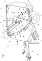
- a press 10 which has a frame 12 which is supported by a chassis 14 on the ground 16.
- the press 10 shown is designed in the manner of a round baler and can be used both in the agricultural and in the industrial sector for the production of a round bale, in particular round cylindrical bale of harvested material, but also of waste, paper, fabric or tissue, cotton, tobacco etc. are used.
- Such a press 10 can be pulled by a work vehicle, not shown, preferably in the manner of a farm tractor, or be designed to be self-propelled.
- a drawbar 20 is provided at the front of the frame 12 to attach the press 10 to a tractor, not shown, and to be able to pull over a field.
- a receiving device 22 in the form of a pick-up serves to receive lying on the ground 16 crop, z. B. of stored in a swath hay or straw. The picked up by the receiving device 22 crop is fed to an inlet 24 a baling chamber 26 and rolled up there spirally to a round cylindrical bale, tied and then deposited on the substrate 16.
- the baling chamber 26 is further formed by an endless pressing means 34, which according to the present embodiment is designed in the form of two juxtaposed pressing belts and by a number of stationary rollers 36, 38, 40, 42 and movable rollers 44, 42, 46, 48 , 50, 52, 54, 56.
- the pressing means 34 has an outer side 34a facing the frame 12 and an inner side 34b.
- baling chamber 26 is circumferentially substantially surrounded by the pressing means 34 and the rollers 28, 30 and 32, it is bounded laterally by side walls, not shown.
- rollers 50, 52, 54, 56 of the movable rollers 44 - 56 are freely rotatably mounted in a lower portion 58 of a delta-shaped support 60 which is pivotally articulated about its upper tip 62 about a horizontally and transversely to the forward axis 64 and with an actor (not shown) from the in Fig. 1 Bale formation position shown can be brought into a pivoted to the rear and top bale ejection position.
- a tensioning mechanism 66 for tightening the pressing means 34 has a tensioning lever 68, which cooperates with a first tensioning element (not shown), and a tensioning arm 72 cooperating with a second tensioning element 70.
- Both the clamping element, not shown, and the clamping element 72 may be formed in the usual way as a mechanical spring or as a hydraulic motor and / or have such.
- the tensioning lever 68 is mounted in the region of the sidewalls, not shown, about an axis 74 running horizontally and transversely to the forward direction and carries two of the movable rollers 46, 48 and cleaning rollers 46a, 48a assigned to these rollers 46, 48 in an end region 76 facing away from the axis 74.
- the clamping arm 72 is mounted correspondingly about an axis 78 and carries in one end 80 one of the movable rollers 44.
- the clamping arm 68 is operatively connected to the clamping element 70 at one end, the other end with the press or their frame 12 in a manner not shown connected is.
- the pressing means 34 is always so firmly applied to the rotationally driven, stationary roller 38 by means of the clamping arm 70, that its entrainment is ensured.
- the roller 36 is driven in rotation.
- the pressing means 34 assumes an initial state in which it just straightens the inlet 24 bridges, and a final state in which it winds around a bale like a large loop.
- the baling chamber 26 is thus variable in size, d. H. its diameter increases with the size of the bale 18.
- the bale is in its formation in the baling chamber 26 and is largely wrapped by the pressing means 34, but falls from the baling chamber 26 to the rear on the ground 16, as soon as the carrier 60 with the movable rollers 50 - 56 opposite to the drawing swings upwards in a clockwise direction.
- the bale can also be deposited on a device downstream of the press 10, for example in the manner of a device for wrapping the bale with a mesh or foil material.
- the illustrated embodiment of the baler is in the EP 1 308 078 A1 disclosed in detail.
- Other possible embodiments are in the DE 198 51 470 A1 .
- a scraper 84 is provided to deposits or adhesions to the pressing means 34 and the outside of the pressing means 34a, for example in the form of particular wet or wet crop, such as grass, dirt or other Material to scrape or strip from the pressing means 34 and its outer portion 34a.
- the scraper device 84 has a Scratch bar support 86 and a scratch bar 88.
- the scraper carrier 86 is connected via a hinge 90 pivotally connected to a frame portion 12a of the press 10 and carries the other end according to the present embodiment of a flexible plastic material existing scratch strip 88, which may be formed for example in the form of a hard rubber strip or - lip
- the scraper carrier 86 is pivotally connected via the hinge 90 with a portion 12 a of the frame 12 together with a hinge lever 92.
- the articulated lever 92 in turn is connected via a connecting element 94 and a spring means 96 exhibiting connecting means 98 with a clamping arm 100 which is pivotally mounted with the clamping arm 72 about the same axis 78 so that it can optionally pivot together with this.
- the clamping arm 72 takes during the bale forming process in FIG. 2a shown and related to the press room 12 pivoted to the bottom right position. After completion of the bale forming process and any binding or wrapping with net or film material connected thereto, a delta-shaped carrier 60 is pivoted backwards and forwards.
- the measures provided for on the support 60 rollers 50 and 56 take the pressing means 34 in a similar position, whereby the previously in the press room 26 wrapped by the pressing means 34 bales released by the pressing means 34, discharged from the pressing chamber 26 and on the ground 16 or a connected device, such as a device for wrapping the bale with a net or film material is stored.
- the tensioning lever 68 begins to move back in the direction of its lower, inward direction FIG. 1 to move shown position.
- the tension of the pressing means 34 is now maintained by a movement of the clamping arm 72 upwards. Any slip that may occur can thus be absorbed and / or prevented.
- the clamping arm 72 pivots about the axis 78 short-term upward, causing the Schwenkarmhebel 100 pivoted downward. This downward movement is transmitted via the connecting means 98 to the articulated lever 92, which the Kriskleistenly 86 and thus the scratching bar 88 down into the in FIG.
- the spring means 96 can ensure in this position that the scratch bar 88 on the outer portion 34 a the pressing means 34 abuts evenly and / or a deflection of the scraper bar 88, the Kratzancenträges 86 and the hinge lever 92 in case of overload, generated by, for example, a stone arrived in this area, highly compacted deposits or the like, allow. In this way, damage to the scraper 84 can be prevented and / or optimal function can be ensured.
Landscapes
- Life Sciences & Earth Sciences (AREA)
- Environmental Sciences (AREA)
- Storage Of Harvested Produce (AREA)
Abstract
Description
- Die vorliegende Erfindung betrifft eine Abstreifereinrichtung zur Verminderung von Anhaftungen an einem mit einem Ballen zusammenwirkenden Pressmittel einer landwirtschaftlichen Rundballenpresse, mit einem eine Kratzleiste tragenden Kratzleistenträger, wobei der Kratzleistenträger mit einer Rundballenpresse verschwenkbar verbindbar ist, und mit dem Kratzleistenträger zumindest eine erste Stellung, in der die Kratzleiste wirksam an ein Pressmittel angrenzbar ist, und eine zweite Stellung einnehmbar ist, in der die Kratzleiste von einem Pressmittel abhebbar ist. Ferner betrifft die vorliegende Erfindung eine Presse mit einer Abstreifereinrichtung und ein Verfahren zum Betrieb einer Presse.
- Bekannte Abstreifereinrichtungen werden häufig an Pressen eingesetzt, welche bewegliche Teile aufweisen, die mit durch die Pressen zu verarbeitendem Pressgut in Berührung kommen. Die Abstreifereinrichtungen weisen Kratzleisten auf, die mit den beweglichen Teilen der Presse zusammenwirken, um Anhaftungen von Pressgut und anderem Material, wie Schmutz, Erde, Pressgutresten etc. entgegenzuwirken, solchen vorzubeugen oder bereits bestehende Anhaftungen oder Ablagerungen zu entfernen. Bei den bewegliche Teilen handelt es sich häufig um Pressmittel in der Art von Gurten bzw. Riemen. Es sind aber auch Abstreifereinrichtungen bekannt, die entsprechend mit Rollen oder Walzen einer Presse zusammenwirken.
- Derartige Pressen werden sowohl im landwirtschaftlichen als auch im industriellen Bereich eingesetzt. Entsprechende landwirtschaftliche Pressen dienen beispielsweise zur Bildung von Erntegutballen, beispielsweise in der Art von Rundballen, und erzeugen häufig zumindest im wesentlichen rundzylindrische Ballen aus Erntegut, beispielsweise in der Art von Stroh, Heu, Häckselgut etc.. Industrielle Pressen finden Verwendung bei der Verdichtung von Müll, Textilien oder anderen Stoffen bzw. bei deren Pressung zu Ballen.
- Es sind Abstreifereinrichtungen für Pressmittel in der Art von Gurten bzw. Riemen bekannt, die einen eine Kratzleiste tragenden Kratzleistenträger aufweisen, der beweglich an einer Presse angebracht ist. Derartige Abstreifereinrichtungen funktionieren häufig, insbesondere bei schwierigen Erntebedingungen wie beispielsweise nassem Erntegut, nicht optimal.
- Die der Erfindung zugrunde liegende Aufgabe wird darin gesehen, eine Abstreifereinrichtung, eine Presse und ein Verfahren der eingangs genannten Art anzugeben, durch welche die vorgenannten Nachteile überwunden werden.
- Die Aufgabe wird erfindungsgemäß durch die Lehre der Patentansprüche 1, 8 bzw. 10 gelöst. Weitere vorteilhafte Ausgestaltungen und Weiterbildungen der Erfindung gehen aus den Unteransprüchen hervor.
- Eine Abstreifereinrichtung zur Verminderung von Anhaftungen an einem beweglichen Bauteil einer Presse, insbesondere einem mit einem Ballen zusammenwirkenden Pressmittel, weist einen eine Kratzleiste tragenden Kratzleistenträger auf. Der Kratzleistenträger ist mit der Presse beweglich verbindbar vorgesehen und kann zumindest eine erste Stellung, in der die Kratzleiste wirksam an das Pressmittel angrenzt, und eine zweite Stellung einnehmen, in der die Kratzleiste von dem Pressmittel abgehoben ist. Es ist denkbar, dass der Kratzleistenträger verschiebbar oder anderweitig bewegbar vorgesehen ist. Vorzugsweise ist er aber schwenkbar mit der Presse verbindbar. Es ist vorgesehen, dass die Kratzleiste ihre abgehobene Stellung zyklisch einnimmt. Durch das regelmäßige, im Rahmen eines Zyklus erfolgende Abheben der Kratzleiste von dem Pressmittel, wird einer Anhäufung von insbesondere abgekratztem Material auf der Kratzleiste entgegengewirkt, da dieses beim Abheben oder im abgehobenen und damit von dem Pressmittel beabstandeten Zustand der Kratzleiste regelmäßig von dieser, wie auch von dem Kratzleistenträger bzw. der Abstreifereinrichtung als solches ab- bzw herabfallen kann. Auf diese Weise kann Verstopfungen und/oder Fehlfunktionen, wie sie insbesondere bei nassen Bedingungen und/oder feuchtem Press- bzw. Erntegut durch sich anhäufendes und verklumpendes Material auftreten können, vorgebeugt werden. Dies ist darüber hinaus auch ästhetisch vorteilhaft. Die Presse ist in der Art einer landwirtschaftlichen Rundballenpresse ausgebildet. Die Abstreifereinrichtung kann aber auch an anderen Pressen, beispielsweise an industriellen Pressen eingesetzt werden. Weiterhin ist die Anwendung nicht auf den Einsatz an Rundballenpressen beschränkt.
- In vorteilhafter Weise ist das Pressmittel in der Art eines endlosen Pressmittels, insbesondere einem Pressriemen oder - gurt, ausgebildet und/oder weist wenigstens ein endloses Pressmittel, insbesondere einen Pressriemen bzw. -gurt auf. Es können aber auch eine Mehrzahl von oder gemäß der bevorzugten Ausführungsform zwei endlose Pressmittel vorgesehen sein. Das Pressmittel kann aber auch in der Art einer Rolle oder Walze oder in jeder anderen geeigneten Weise ausgebildet sein oder derartige aufweisen.
- Es ist denkbar, dass der Zyklus von einer Steuer- oder Regeleinrichtung der Presse bestimmt wird. Vorzugsweise wird der Zyklus aber durch eine Baugruppe und insbesondere durch eine bereits einem zyklischen Ablauf folgende Baugruppe der Presse bestimmt. Auf diese Weise kann auf eine separate Steuer oder Regelung der Abstreifereinrichtung verzichtet werden, da der Zyklus bzw. der Ablauf bereits durch diese Baugruppe, deren Funktion bzw. deren Steuer- oder Regelung vorgeben wird. Auch kann der Zyklus bzw. die Funktion der Abstreifereinrichtung auf diese Weise mit einer oder mehreren Baugruppen der Presse synchronisiert werden, ohne dass hierzu aufwendige Maßnahmen ergriffen werden müssen. Besonders günstig ist es, wenn der Zyklus durch einen Spannmechanismus der Presse, insbesondere eine Spannmechanismus für das Pressmittel bestimmt wird.
- Der Spannmechanismus kann wenigstens einen, vorzugsweise direkt oder indirekt verschwenk- bzw. verdrehbar mit der Presse verbindbaren und insbesondere mit einem Spannelement zusammenwirkenden Spannarm aufweisen. Derartige Spannarme folgen während der Ballenbildung oder nach Abschluss der Ballenbildung und/oder beim Auswerfen des Ballens aus einem Pressraum einem zumindest im Wesentlichen zyklischen Bewegungsablauf. Ist der Spannarm mit dem Kratzleistenträger wirksam verbunden, so kann der Kratzleistenträger einer Bewegung des Spannarms zumindest bereichsweise folgen. Auf diese Weise kann der zyklische Bewegungsablauf des Spannarms in einfacher Art und Weise an den Kratzleistenträger übertragen werden und/oder es kann in einfacher Weise ein zumindest teilweise synchronisiertes bzw. abhängiges Verschwenken realisiert werden.
- Besonders günstig ist es, wenn der Kratzleistenträger gemeinsam mit einem Gelenkhebel um eine Achse verschwenkbar an dem Rahmen vorgesehen ist. Der Gelenkhebel kann dabei über ein Verbindungsmittel mit dem Spannarm zusammenwirken. Weist das Verbindungsmittel wenigstens ein Verbindungselement und ein mit diesem zusammenwirkendes Federmittel auf, so können diese derart beispielsweise als eine Überlastsicherung wirken, dass sie im Falle einer beispielsweise durch einen Stein oder durch eine besonders große oder harte Anhaftung von Material verursachten Überlastung ein Wegschwenken der Kratzleiste erlauben, so dass einer Beschädigung der Abstreifereinrichtung vorgebeugt werden kann. Eine solche Einrichtung kann aber auch alternativ oder zusätzlich dazu dienen, ein Anliegen der Kratzleiste als solches als auch insbesondere unter Einhaltung und/oder Aufrechterhaltung einer vorgegebenen Spannung an dem Pressmittel zu gewährleisten. Auf diese Weise kann die Funktion der Abstreifereinrichtung weiter verbessert werden.
- Es ist denkbar, die Kratzleiste aus einem starren Material und/oder auch einteilig mit dem Kratzleistenträger vorzusehen. Ist die Kratzleiste aber als separates und insbesondere mit dem Kratzleistenträger lösbar verbindbares Bauteil ausgebildet, so kann sie aus einem anderen Material als der Kratzleistenträger hergestellt werden und/oder im Falle von Verschleiß oder Beschädigung oder auch zur Anpassung an andere Erntebedingungen ausgetauscht werden. Auch ein Nachstellen der Position der Kratzleiste bezogen auf den Kratzleistenträger ist auf diese Art und Weise möglich. Besonders günstig ist es, wenn die Kratzleiste zumindest bereichsweise flexibel, vorzugsweise aber in der Art einer Hartgummileiste oder -lippe ausgebildet ist.
- Besonders günstig ist es, wenn der Spannmechanismus zumindest unter anderem vorgesehen ist, um beim Öffnen des Ballenpressraums und/oder beim Auswerfen des Ballens eine gegebenenfalls vorgebbare Spannung des Pressmittels aufrechtzuerhalten und/oder auftretenden Schlupf aufzunehmen. Es ist aber auch denkbar, dass der Spannmechanismus das Pressmittel während der Ballenbildung oder anderweitig mit Spannung beaufschlagt.
- Wird eine Presse mit einer oder mehreren der zuvor beschriebenen Abstreifereinrichtungen ausgestattet, so kann dies die Funktion der Presse unterstützen, indem Anhaftungen oder Ablagerungen an einem oder mehreren Pressmittel(n) in besonders günstiger Art und Weise vorgebeugt werden kann. Die Abstreifereinrichtung oder auch eine oder mehrere der Abstreifereinrichtungen kann/können in einem einer Deichsel zugewandten Bereich des Ballenpressraums angeordnet sein. Diese Anordnung ist besonders günstig, da die Abstreifereinrichtung in diesem Bereich relativ geschützt vor äußeren Einwirkungen angebracht werden kann. Es ist aber auch eine Anordnung in einem anderen Bereich, beispielsweise in einem rückwärtigen Bereich der Presse denkbar. Vorzugsweise wirkt die Abstreifereinrichtung mit einer Außenseite, im gezeigten Ausführungsbeispiel einer dem Pressraum abgewandten bzw. einem Rahmen der Presse zugewandten Seite und/oder Fläche, des Pressmittels zusammen. Es ist aber denkbar, dass die Abstreifereinrichtung mit einer entsprechenden Innenseite des Pressmittels zusammenwirkt. Dies im Besonderen, wenn das Pressmittel als ein endloses Pressmittel, beispielsweise in der Art eines Pressriemens bzw. -gurtes ausgebildet ist oder ein(ein) solche(s)n aufweist. Bei der Ballenpresse handelt es sich insbesondere um eine landwirtschaftliche Ballenpresse zur Bildung rundzylindrischer Ballen. Die Presse kann aber auch im industriellen Bereich, beispielsweise zur Bildung von Ballen aus Papier, Müll, Stoff oder anderen Materialien eingesetzt werden. Es ist auch eine Verwendung an einer Presse zur Bildung quaderförmiger oder sonstiger Ballen denkbar.
- Gemäß einem Verfahren zum Betrieb einer zuvor beschriebenen Presse kann die Abstreifereinrichtung während der Bildung eines Ballens in dem Ballenpressraum derart mit dem Pressmittel zusammenwirken, dass vorzugsweise an der Außenseite des Pressmittel angelagerte Ablagerungen durch die Abstreifereinrichtung bzw. die Kratzleiste von dem Pressmittel bzw. dessen Außenseite zumindest teilweise entfernt wird/werden kann. Während eines Öffnens des Pressraums zum Auswerfen eines Ballens bzw. dem Auswerfen eines Ballens wirkt die Abstreifereinrichtung nicht (länger) mit dem Pressmittel zusammen bzw. die Kratzleiste wird in eine von dem Pressmittel bzw. dessen Außenseite abgehobene bzw. beabstandete Stellung gebracht, insbesondere in der Art, dass zuvor abgestreifte Ablagerungen von der Abstreifereinrichtung bzw. der Kratzleiste herabfallen können.
- Ist die Abstreifereinrichtung wirksam mit einem Spannmechanismus verbunden, der insbesondere beim Öffnen des Ballenpressraums und/oder beim Auswerfen eines Ballens aus dem Ballenpressraum eine gegebenenfalls vorgebbare Spannung des Pressmittels gewährleistet und/oder gegebenenfalls auftretenden Schlupf aufnimmt, so kann die Abstreifereinrichtung bzw. eines oder mehrere ihrer Bauteile in einfacher Weise der zyklischen Arbeitsweise dieses Spannmechanismus folgen. Es darüber hinaus denkbar, dass die Spanneinrichtung eine/mehrere alternative und/oder zusätzliche Funktionalität(en) aufweist.
- Anhand der Zeichnung, die ein Ausführungsbeispiel der Erfindung zeigt, werden nachfolgend die Erfindung sowie weitere Vorteile und vorteilhafte Weiterbildungen der Erfindung und Ausgestaltungen der Erfindung näher beschrieben und erläutert.
- Es zeigt:
- Fig. 1
- eine Presse in Seitenansicht mit einer Abstreifereinrichtung,
- Fig. 2a
- die Abstreifereinrichtung aus
Figur 1 in einer vergrößerten Darstellung in einer ersten Stellung und - Fig. 2b
- die Abstreifereinrichtung aus
Figur 1 in einer vergrößerten Darstellung in einer zweiten Stellung. - In der
Fig. 1 ist eine Ausführungsform einer Presse 10 dargestellt, die einen Rahmen 12 aufweist, der sich über ein Fahrwerk 14 auf dem Untergrund 16 abstützt. Die gezeigte Presse 10 ist in der Art einer Rundballenpresse ausgebildet und kann sowohl im landwirtschaftlichen als auch im industriellen Bereich zur Herstellung eines üblicherweise als Rundballen bezeichneten, insbesondere rundzylindrischen Ballens aus Erntegut, aber auch aus Müll, Papier, Stoff bzw. Gewebe, Baumwolle, Tabak etc. eingesetzt werden. Eine solche Presse 10 kann von einem nicht gezeigten Arbeitsfahrzeug, vorzugsweise in der Art eines Ackerschleppers, gezogen werden oder auch selbstfahrend ausgebildet sein. - Gemäß dem vorliegenden Ausführungsbeispiel ist an der Vorderseite des Rahmens 12 eine Deichsel 20 vorgesehen, um die Presse 10 an einem nicht gezeigten Ackerschlepper anhängen und über ein Feld ziehen zu können. Eine Aufnahmevorrichtung 22 in Form einer Pick-Up dient zur Aufnahme von auf dem Untergrund 16 liegenden Erntegut, z. B. von in einem Schwad abgelegten Heu oder Stroh. Das von der Aufnahmevorrichtung 22 aufgenommene Erntegut wird einem Einlass 24 einem Ballenpressraums 26 zugeführt und dort spiralförmig zu einem rundzylindrischen Ballen aufgerollt, gebunden und anschließend auf dem Untergrund 16 abgelegt.
- Am Einlass 24 des Ballenpressraums 26 sind eine untere, stationäre Rolle 28 und zwei obere Rollen 30, 32 positioniert. Der Ballenpressraum 26 wird weiterhin durch ein endloses Pressmittel 34 gebildet, das gemäß der vorliegenden Ausführungsform in der Art zweier nebeneinander anliegender Pressriemen ausgeführt ist und um eine Anzahl von ortsfesten Walzen 36, 38, 40, 42 und bewegbaren Walzen 44 , 42, 46, 48, 50, 52, 54, 56 geführt wird. Das Pressmittel 34 weist eine dem Rahmen 12 zugewandte Außenseite 34a und eine Innenseite 34b auf.
- Während der Ballenpressraum 26 umfangsseitig im Wesentlichen von dem Pressmittel 34 und den Rollen 28, 30 und 32 umgeben wird, wird er seitlich von nicht gezeigten Seitenwänden begrenzt.
- Vier Walzen 50, 52, 54, 56 der bewegbaren Walzen 44 - 56 sind in einem unteren Bereich 58 eines deltaförmigen Trägers 60 frei drehbar gelagert, der um seine obere Spitze 62 um eine horizontal und quer zur Vorwärtsrichtung verlaufende Achse 64 schwenkbar angelenkt ist und mit einem Aktor (nicht gezeigt) aus der in
Fig. 1 dargestellten Ballenbildungsposition in eine nach hinten und oben verschwenkte Ballenauswurfposition verbringbar ist. - Ein Spannmechanismus 66 zur Straffung des Pressmittels 34 weist einen Spannhebel 68, der mit einem nicht gezeigten ersten Spannelement zusammenwirkt, und einen mit einem zweiten Spannelement 70 zusammenwirkenden Spannarm 72 auf. Sowohl das nicht gezeigte Spannelement als auch das Spannelement 72 kann in üblicher Weise als eine mechanische Feder oder als ein Hydraulikmotor ausgebildet sein und/oder einen solchen aufweisen.
- Der Spannhebel 68 ist im Bereich der nicht gezeigten Seitenwände um eine horizontal und quer zur Vorwärtsrichtung verlaufende Achse 74 gelagert und trägt in einem der Achse 74 abgewandten Endbereich 76 zwei der bewegbaren Rollen 46, 48 sowie diesen Rollen 46, 48 zugeordnete Reinigungsrollen 46a, 48a. Der Spannarm 72 ist entsprechend um eine Achse 78 gelagert und trägt in einem Endbereich 80 eine der bewegbaren Rollen 44. Darüber hinaus ist der Spannarm 68 mit dem Spannelement 70 einenends wirksam verbunden, das andernends mit der Presse bzw. deren Rahmen 12 in nicht gezeigter Weise verbunden ist.
- Das Pressmittel 34 wird mittels des Spannarms 70 stets so fest an die drehend angetriebene, ortsfeste Walze 38 angelegt, dass seine Mitnahme gewährleistet ist. Auch die Walze 36 wird drehend angetrieben. Das Pressmittel 34 nimmt einen Anfangszustand ein, in dem es gerade gestreckt den Einlass 24 überbrückt, und einen Endzustand, in dem es sich wie eine große Schlaufe um einen Ballen schlingt. Der Ballenpressraum 26 ist somit in seiner Größe veränderlich, d. h. sein Durchmesser nimmt mit der Größe des Ballens 18 zu. Der Ballen befindet sich während seiner Bildung in dem Ballenpressraum 26 und wird von dem Pressmittel 34 größtenteils umschlungen, fällt aber aus dem Ballenpressraum 26 nach hinten auf den Untergrund 16, sobald der Träger 60 mit den beweglichen Walzen 50 - 56 mit Blick auf die Zeichnung entgegen dem Uhrzeigerdrehsinn nach oben schwenkt. Alternativ kann der Ballen auch auf einem der Presse 10 nachgeordneten Gerät, beispielsweise in der Art eines Geräts zur Umhüllung des Ballens mit einem Netz- oder Folienmaterial abgelegt werden.
- Die dargestellte Ausführungsform der Ballenpresse ist in der
EP 1 308 078 A1 detailliert offenbart. Andere, mögliche Ausführungsformen sind in derDE 198 51 470 A1 ,DE 102 41 215 A1 und derEP 1 264 531 A1 beschrieben. Die Offenbarungen dieser Dokumente werden durch Verweis mit in die vorliegenden Unterlagen aufgenommen. - In einem der Deichsel 20 zugewandten Bereich 82 der Ballenpresse 10 ist eine Abstreifereinrichtung 84 vorgesehen, um Ablagerungen oder Anhaftungen an dem Pressmittel 34 bzw. dem Außenbereich des Pressmittels 34a beispielsweise in der Art von insbesondere feuchtem bzw. nassem Erntegut, beispielsweise Gras, Schmutz oder anderem Material, von dem dem Pressmittel 34 bzw. dessen Außenbereich 34a abzukratzen bzw. abzustreifen. Die Abstreifereinrichtung 84 weist einen Kratzleistenträger 86 und eine Kratzleiste 88 auf. Der Kratzleistenträger 86 ist über ein Gelenk 90 schwenkbar mit einem Rahmenbereich 12a der Presse 10 verbunden und trägt andernends die gemäß dem vorliegenden Ausführungsbeispiel aus einem flexiblen Kunststoffmaterial bestehende Kratzleiste 88, die beispielsweise in der Art einer Hartgummileiste oder - lippe ausgebildet sein kann
- Es wird nun auch auf die
Figuren 2a und2b Bezug genommen, in denen die Abstreifereinrichtung 84 genauer dargestellt wird. Der Kratzleistenträger 86 ist über das Gelenk 90 mit einem Bereich 12a des Rahmens 12 gemeinsam mit einem Gelenkhebel 92 schwenkbar verbunden. Der Gelenkhebel 92 wiederum ist über ein ein Verbindungselement 94 und ein Federmittel 96 aufweisendes Verbindungsmittel 98 mit einem Spannarmhebel 100 verbunden, der mit dem Spannarm 72 um die gleiche Achse 78 derart schwenkbar gelagert ist, dass er mit diesem gegebenenfalls gemeinsam verschwenken kann. - Im Folgenden soll nun auf die Funktionsweise der Abstreifereinrichtung 84 genauer eingegangen werden. Hierzu wird auf die
Figur 1 sowie auf dieFiguren 2a und2b Bezug genommen. - Der Spannarm 72 nimmt während des Ballenbildungsvorgangs die in
Figur 2a gezeigte und bezogen auf die den Pressraum 12 nach rechts unten verschwenkte Stellung ein. Nach Beendigung des Ballenbildungsvorgangs und einer eventuell an diesen angeschlossenen Bindung oder einer Umhüllung mit Netz- oder Folienmaterial wird ein deltaförmiger Träger 60 nach rückwärts und oben verschwenkt. Die an dem Träger 60 vorgesehenen Walzen 50 und 56 nehmen das Pressmittel 34 mit in eine ebensolche Position, wodurch der im Pressraum 26 bisher von dem Pressmittel 34 umschlungene Ballen von dem Pressmittel 34 freigegeben, aus dem Pressraum 26 abgegeben und auf dem Untergrund 16 oder einem angeschlossenen Gerät, beispielsweise einem Gerät zur Umhüllung des Ballens mit einem Netz- oder Folienmaterial, abgelegt wird. - Schwenkt der deltaförmige Träger 60 und somit die an ihm angebrachten Walzen 50, 56 und das Pressmittel 34 nach rückwärts und oben, so beginnt sich der Spannhebel 68 zurück in Richtung seiner unteren, in
Figur 1 gezeigten Position zu bewegen. Kurzfristig wird die Spannung des Pressmittels 34 nun durch eine Bewegung des Spannarms 72 nach oben aufrechterhalten. Möglicherweise auftretender Schlupf kann so aufgenommen und/oder diesem vorgebeugt werden. Der Spannarm 72 verschwenkt um die Achse 78 kurzfristig nach oben, wodurch der Schwenkarmhebel 100 nach unten verschwenkt. Diese nach unten gerichtete Bewegung wird über das Verbindungsmittel 98 an den Gelenkhebel 92 übertragen, welcher den Kratzleistenträger 86 und somit die Kratzleiste 88 nach unten in die inFigur 2b dargestellte, abgehobene bzw. dem Pressmittel 34 bzw. dem Außenbereich 34a des Pressmittels 34 abgelegene Stellung bringt. In dieser Stellung kann möglicherweise auf der Abstreifereinrichtung 84 bzw. dem Kratzleistenträger 86 und/oder der Kratzleiste 88 abgelagertes Material von diesem herabfallen. Im Anschluss verschwenkt der Spannarm 72 durch die Wirkung des Spannmittels 70 wieder in Richtung seiner an den Außenbereich 34a des Pressmittels 34 angrenzenden, inFigur 2a gezeigten Stellung. Das Federmittel 96 kann in dieser Stellung sicherstellen, dass die Kratzleiste 88 an dem Außenbereich 34a des Pressmittels 34 gleichmäßig anliegt und/oder ein Ausweichen des Kratzleiste 88, des Kratzleistenträges 86 bzw. des Gelenkhebels 92 in Falle einer Überbelastung, erzeugt durch beispielsweise einen in diesem Bereich gelangten Stein, hochverdichtete Ablagerungen oder ähnlichem, erlauben. Auf diese Weise kann einer Beschädigung der Abstreifereinrichtung 84 vorgebeugt und/oder eine optimale Funktion gewährleistet werden.
Claims (11)
- Abstreifereinrichtung (84) zur Verminderung von Anhaftungen an einem mit einem Ballen zusammenwirkenden Pressmittel (34) einer landwirtschaftlichen Rundballenpresse (10), mit einem eine Kratzleiste (88) tragenden Kratzleistenträger (86), wobei der Kratzleistenträger (86) mit einer Rundballenpresse (10) verschwenkbar verbindbar ist, und mit dem Kratzleistenträger (86) zumindest eine erste Stellung, in der die Kratzleiste (88) wirksam an ein Pressmittel (34) angrenzbar ist, und eine zweite Stellung einnehmbar ist, in der die Kratzleiste (88) von einem Pressmittel (34) abhebbar ist, dadurch gekennzeichnet, dass die Kratzleiste (88) die zweite, abgehobene Stellung zyklisch einnimmt.
- Abstreifereinrichtung (84) nach Anspruch 1, dadurch gekennzeichnet, dass ein Pressmittel (34) in der Art eines endlosen Pressmittels, insbesondere eines Pressriemens oder -gurts, ausbildbar ist.
- Abstreifereinrichtung (84) nach Anspruch 1 oder 2, dadurch gekennzeichnet, dass der Zyklus von einem Spannmechanismus (66) für ein Pressmittel (34), bestimmt wird.
- Abstreifereinrichtung (84) nach Anspruch 3, dadurch gekennzeichnet, dass der Spannmechanismus (66) wenigstens einen, vorzugsweise direkt oder indirekt verschwenk- bzw. verdrehbar mit einer Rundballenpresse (10) verbindbaren und insbesondere mit einem Spannelement (70) zusammenwirkenden Spannarm (72) aufweist, wobei der Spannarm (72) vorzugsweise mit dem Kratzleistenträger (86) derart wirksam verbunden ist, dass der Kratzleistenträger (86) der Bewegung des Spannarms (72) zumindest bereichsweise folgt.
- Abstreifereinrichtung (84) nach Anspruch 4, dadurch gekennzeichnet, dass der Kratzleistenträger (86) gemeinsam mit einem Gelenkhebel (92) um eine Achse (90) verschwenkbar vorgesehen ist und der Gelenkhebel (92) über ein Verbindungsmittel (98) mit dem Spannarm (72) zusammenwirkt, wobei das Verbindungsmittel (98) ein Verbindungselement (94) und ein mit diesem zusammenwirkendes Federmittel (96) aufweist.
- Abstreifereinrichtung (84) nach einem der vorherigen Ansprüche, dadurch gekennzeichnet, dass die Kratzleiste (88) zumindest bereichsweise flexibel, vorzugsweise aber in der Art einer Hartgummileiste oder -lippe ausgebildet ist.
- Abstreifereinrichtung (84) nach einem Ansprüche 3 bis 6, dadurch gekennzeichnet, dass der Spannmechanismus (66) zumindest unter anderem vorgesehen ist, um beim Öffnen eines Ballenpressraums (26) und/oder beim Auswerfen eines Rundballens eine gegebenenfalls vorgebbare Spannung für das Pressmittel (34) aufrechtzuerhalten.
- Rundballenpresse (10), insbesondere landwirtschaftliche Rundballenpresse zur Bildung rundzylindrischer Ballen, mit einem Pressmittel (34) und einer Abstreifereinrichtung (84) nach einem der vorherigen Ansprüche.
- Rundballenpresse (10) nach Anspruch 8, wobei die Abstreifereinrichtung (84) vorzugsweise in einem einer Deichsel (20) zugewandten Bereich (82) eines Ballenpressraums (26) der Rundballenpresse (10) angeordnet ist und vorzugsweise mit einer Außenseite (34a) des Pressmittels (34) zusammenwirken kann.
- Verfahren zum Betrieb einer Rundballenpresse (10) mit einer Abstreifereinrichtung (84) nach einem der Ansprüche 1 bis 7, dadurch gekennzeichnet, dass die Abstreifereinrichtung (84) während der Bildung eines Ballen in einem Ballenpressraum (26) derart mit einem Pressmittel (34) zusammenwirkt, dass vorzugsweise an der Außenseite (34a) des Pressmittels (34) angelagerte Ablagerungen durch die Abstreifereinrichtung (84) von dem Pressmittel (34) bzw. dessen Außenseite (34) zumindest teilweise entfernt wird und insbesondere während des Öffnens des Ballenpressraums (26) zum Auswerfen eines Ballens bzw. des Auswerfens eines Ballens nicht mit dem Pressmittel (34) zusammenwirkt bzw. die Kratzleiste (88) eine von dem Pressmittel (34) bzw. dessen Außenseite (34a) abgehobene Stellung gebracht wird, insbesondere in der Art, dass zuvor abgestreifte Ablagerungen von der Abstreifereinrichtung (84) bzw. der Kratzleiste (88) herabfallen können.
- Verfahren nach Anspruch 10, dadurch gekennzeichnet, dass die Abstreifereinrichtung (84) wirksam mit einem Spannmechanismus (66) verbunden ist, der insbesondere beim Öffnen des Ballenpressraums (26) und/oder beim Auswerfen eines Ballens aus dem Ballenpressraum (26) eine gegebenenfalls vorgebbare Spannung des Pressmittels (34) gewährleistet und/oder gegebenenfalls auftretenden Schlupf aufnimmt.
Applications Claiming Priority (1)
| Application Number | Priority Date | Filing Date | Title |
|---|---|---|---|
| DE102016204481.8A DE102016204481A1 (de) | 2016-03-17 | 2016-03-17 | Abstreifereinrichtung, Presse und Verfahren |
Publications (2)
| Publication Number | Publication Date |
|---|---|
| EP3222134A1 true EP3222134A1 (de) | 2017-09-27 |
| EP3222134B1 EP3222134B1 (de) | 2020-08-19 |
Family
ID=58347290
Family Applications (1)
| Application Number | Title | Priority Date | Filing Date |
|---|---|---|---|
| EP17161372.2A Active EP3222134B1 (de) | 2016-03-17 | 2017-03-16 | Rundballenpresse und verfahren |
Country Status (3)
| Country | Link |
|---|---|
| US (1) | US10588264B2 (de) |
| EP (1) | EP3222134B1 (de) |
| DE (1) | DE102016204481A1 (de) |
Cited By (2)
| Publication number | Priority date | Publication date | Assignee | Title |
|---|---|---|---|---|
| EP3714670A1 (de) * | 2019-03-29 | 2020-09-30 | Maschinenfabrik Bernard Krone GmbH & Co. KG | Landwirtschaftliche runballenpresse |
| EP3847885B1 (de) | 2020-01-13 | 2023-08-09 | CNH Industrial Belgium N.V. | Landwirtschaftliche ballenpresse mit unabhängigen spannarmen |
Families Citing this family (5)
| Publication number | Priority date | Publication date | Assignee | Title |
|---|---|---|---|---|
| DE102022113276A1 (de) * | 2022-05-25 | 2023-11-30 | Usines Claas France S.A.S | Landwirtschaftliche Ballenpresse mit einer Spanneinrichtung für einen Zugmitteltrieb |
| IT202200013816A1 (it) | 2022-06-30 | 2023-12-30 | Kverneland Group Ravenna Srl | Imballatore |
| IT202200013804A1 (it) | 2022-06-30 | 2023-12-30 | Kverneland Group Ravenna Srl | Imballatore |
| CN115067086B (zh) * | 2022-07-04 | 2024-04-16 | 呼伦贝尔市海征机械制造有限责任公司 | 一种捆草机打包装置 |
| DE102023114691A1 (de) * | 2023-06-05 | 2024-12-05 | Deere & Company | Rundballenpresse und Verfahren |
Citations (7)
| Publication number | Priority date | Publication date | Assignee | Title |
|---|---|---|---|---|
| US4155298A (en) * | 1977-03-21 | 1979-05-22 | Hesston Corporation | Bale starting gate for rotary baler |
| DE69308059T2 (de) * | 1992-04-16 | 1997-06-12 | Ford New Holland Nv | Walzenabstreifeinrichtung für eine Rundballenpresse |
| US5913805A (en) * | 1997-07-11 | 1999-06-22 | New Holland North America, Inc. | Trash baffle for round baler apparatus |
| DE19851470A1 (de) | 1998-11-09 | 2000-05-11 | Lely Welger Maschinenfabrik | Rundballenpresse für landwirtschaftliches Erntegut |
| EP1264531A1 (de) | 2001-06-06 | 2002-12-11 | Deere & Company | Rundballenpresse |
| EP1308078A1 (de) | 2001-10-30 | 2003-05-07 | Deere & Company | Rundballenpresse |
| DE10241215A1 (de) | 2002-09-06 | 2004-03-18 | Deere & Company, Moline | Rundballenpresse mit Wägeeinrichtung |
Family Cites Families (6)
| Publication number | Priority date | Publication date | Assignee | Title |
|---|---|---|---|---|
| US4768645A (en) * | 1987-02-20 | 1988-09-06 | Farris Sammy D | Conveyor belt scraping apparatus |
| GB9312228D0 (en) * | 1993-06-14 | 1993-07-28 | Morin Normand J | Conveyor belt scraper system |
| US5355992A (en) * | 1993-10-15 | 1994-10-18 | Utility Technical Services, Inc. | Belt cleaning apparatus |
| NL1000487C2 (nl) * | 1995-06-02 | 1996-12-03 | Greenland Geldrop Bv | Oogstmachine. |
| US6860378B1 (en) * | 2003-11-11 | 2005-03-01 | Thor Global Enterprises Ltd. | Belt scraper tensioning device |
| US8348406B2 (en) * | 2010-07-30 | 2013-01-08 | Xerox Corporation | Liquid ink delivery system including a flow restrictor that resists air bubble formation in a liquid ink reservoir |
-
2016
- 2016-03-17 DE DE102016204481.8A patent/DE102016204481A1/de not_active Ceased
-
2017
- 2017-03-15 US US15/459,863 patent/US10588264B2/en active Active
- 2017-03-16 EP EP17161372.2A patent/EP3222134B1/de active Active
Patent Citations (7)
| Publication number | Priority date | Publication date | Assignee | Title |
|---|---|---|---|---|
| US4155298A (en) * | 1977-03-21 | 1979-05-22 | Hesston Corporation | Bale starting gate for rotary baler |
| DE69308059T2 (de) * | 1992-04-16 | 1997-06-12 | Ford New Holland Nv | Walzenabstreifeinrichtung für eine Rundballenpresse |
| US5913805A (en) * | 1997-07-11 | 1999-06-22 | New Holland North America, Inc. | Trash baffle for round baler apparatus |
| DE19851470A1 (de) | 1998-11-09 | 2000-05-11 | Lely Welger Maschinenfabrik | Rundballenpresse für landwirtschaftliches Erntegut |
| EP1264531A1 (de) | 2001-06-06 | 2002-12-11 | Deere & Company | Rundballenpresse |
| EP1308078A1 (de) | 2001-10-30 | 2003-05-07 | Deere & Company | Rundballenpresse |
| DE10241215A1 (de) | 2002-09-06 | 2004-03-18 | Deere & Company, Moline | Rundballenpresse mit Wägeeinrichtung |
Cited By (2)
| Publication number | Priority date | Publication date | Assignee | Title |
|---|---|---|---|---|
| EP3714670A1 (de) * | 2019-03-29 | 2020-09-30 | Maschinenfabrik Bernard Krone GmbH & Co. KG | Landwirtschaftliche runballenpresse |
| EP3847885B1 (de) | 2020-01-13 | 2023-08-09 | CNH Industrial Belgium N.V. | Landwirtschaftliche ballenpresse mit unabhängigen spannarmen |
Also Published As
| Publication number | Publication date |
|---|---|
| US20170265399A1 (en) | 2017-09-21 |
| DE102016204481A1 (de) | 2017-09-21 |
| US10588264B2 (en) | 2020-03-17 |
| EP3222134B1 (de) | 2020-08-19 |
Similar Documents
| Publication | Publication Date | Title |
|---|---|---|
| EP3222134B1 (de) | Rundballenpresse und verfahren | |
| DE69323738T2 (de) | Ballenpresszuführmechanismus | |
| DE69711751T2 (de) | Rundballenpresse mit Einwickelvorrichtung | |
| EP4108069B1 (de) | Rundballenpresse | |
| EP1062860B1 (de) | Vorrichtung für Erntefahrzeuge, insbesondere für landwirtschaftliche Aufsammelballenpressen | |
| DE4102034A1 (de) | Rundballenpresse | |
| EP2232981B1 (de) | Landwirtschaftliche Ballenpresse | |
| DE68910003T2 (de) | Ballenpresse. | |
| EP1557080B1 (de) | Ballenpresse | |
| DE10255175A1 (de) | Ballenpresse | |
| EP2556741B1 (de) | Landwirtschaftliche Rundballenpresse | |
| EP2984922A1 (de) | Ballenwickeleinrichtung | |
| EP3501261B1 (de) | Leitmittel, ballenpresse und verfahren | |
| EP3569056B1 (de) | Pressmittelleiteinrichtung und presse | |
| EP3482625A1 (de) | Leiteinrichtung und ballenpresse | |
| EP3421387A1 (de) | Hüllmaterial für eine ballenpresse | |
| DE19539297C1 (de) | Ballenpresse | |
| EP4074162B1 (de) | Rundballenpresse mit starterwalze und elastisch auslenkbarem auslenkelement | |
| EP3406132B1 (de) | Abweisereinrichtung, presse und verfahren | |
| DE102005030702A1 (de) | Erntegutaufnahmeeinrichtung und Erntemaschine | |
| EP4056026A1 (de) | Fördervorrichtung für eine ballenpresse | |
| EP3130216A1 (de) | Ballenpresse und leiteinrichtung | |
| EP3420805B1 (de) | Umhüllungseinrichtung, blockiereinrichtung, ballenpresse und verfahren zur anpassung einer ballenpresse an ein hüllmaterial | |
| DE102004023760B4 (de) | Erntemaschine zum Aufnehmen von landwirtschaftlichem Erntegut | |
| EP3575073B1 (de) | Ballenausstosseinrichtung und ballenpresse |
Legal Events
| Date | Code | Title | Description |
|---|---|---|---|
| AK | Designated contracting states |
Kind code of ref document: A1 Designated state(s): AL AT BE BG CH CY CZ DE DK EE ES FI FR GB GR HR HU IE IS IT LI LT LU LV MC MK MT NL NO PL PT RO RS SE SI SK SM TR |
|
| AX | Request for extension of the european patent |
Extension state: BA ME |
|
| PUAI | Public reference made under article 153(3) epc to a published international application that has entered the european phase |
Free format text: ORIGINAL CODE: 0009012 |
|
| STAA | Information on the status of an ep patent application or granted ep patent |
Free format text: STATUS: THE APPLICATION HAS BEEN PUBLISHED |
|
| STAA | Information on the status of an ep patent application or granted ep patent |
Free format text: STATUS: REQUEST FOR EXAMINATION WAS MADE |
|
| 17P | Request for examination filed |
Effective date: 20180327 |
|
| RBV | Designated contracting states (corrected) |
Designated state(s): AL AT BE BG CH CY CZ DE DK EE ES FI FR GB GR HR HU IE IS IT LI LT LU LV MC MK MT NL NO PL PT RO RS SE SI SK SM TR |
|
| GRAP | Despatch of communication of intention to grant a patent |
Free format text: ORIGINAL CODE: EPIDOSNIGR1 |
|
| STAA | Information on the status of an ep patent application or granted ep patent |
Free format text: STATUS: GRANT OF PATENT IS INTENDED |
|
| INTG | Intention to grant announced |
Effective date: 20200316 |
|
| GRAS | Grant fee paid |
Free format text: ORIGINAL CODE: EPIDOSNIGR3 |
|
| GRAA | (expected) grant |
Free format text: ORIGINAL CODE: 0009210 |
|
| STAA | Information on the status of an ep patent application or granted ep patent |
Free format text: STATUS: THE PATENT HAS BEEN GRANTED |
|
| AK | Designated contracting states |
Kind code of ref document: B1 Designated state(s): AL AT BE BG CH CY CZ DE DK EE ES FI FR GB GR HR HU IE IS IT LI LT LU LV MC MK MT NL NO PL PT RO RS SE SI SK SM TR |
|
| REG | Reference to a national code |
Ref country code: CH Ref legal event code: EP |
|
| REG | Reference to a national code |
Ref country code: DE Ref legal event code: R096 Ref document number: 502017006780 Country of ref document: DE |
|
| REG | Reference to a national code |
Ref country code: AT Ref legal event code: REF Ref document number: 1302907 Country of ref document: AT Kind code of ref document: T Effective date: 20200915 |
|
| REG | Reference to a national code |
Ref country code: IE Ref legal event code: FG4D Free format text: LANGUAGE OF EP DOCUMENT: GERMAN |
|
| REG | Reference to a national code |
Ref country code: LT Ref legal event code: MG4D |
|
| REG | Reference to a national code |
Ref country code: NL Ref legal event code: MP Effective date: 20200819 |
|
| PG25 | Lapsed in a contracting state [announced via postgrant information from national office to epo] |
Ref country code: BG Free format text: LAPSE BECAUSE OF FAILURE TO SUBMIT A TRANSLATION OF THE DESCRIPTION OR TO PAY THE FEE WITHIN THE PRESCRIBED TIME-LIMIT Effective date: 20201119 Ref country code: HR Free format text: LAPSE BECAUSE OF FAILURE TO SUBMIT A TRANSLATION OF THE DESCRIPTION OR TO PAY THE FEE WITHIN THE PRESCRIBED TIME-LIMIT Effective date: 20200819 Ref country code: PT Free format text: LAPSE BECAUSE OF FAILURE TO SUBMIT A TRANSLATION OF THE DESCRIPTION OR TO PAY THE FEE WITHIN THE PRESCRIBED TIME-LIMIT Effective date: 20201221 Ref country code: LT Free format text: LAPSE BECAUSE OF FAILURE TO SUBMIT A TRANSLATION OF THE DESCRIPTION OR TO PAY THE FEE WITHIN THE PRESCRIBED TIME-LIMIT Effective date: 20200819 Ref country code: NO Free format text: LAPSE BECAUSE OF FAILURE TO SUBMIT A TRANSLATION OF THE DESCRIPTION OR TO PAY THE FEE WITHIN THE PRESCRIBED TIME-LIMIT Effective date: 20201119 Ref country code: GR Free format text: LAPSE BECAUSE OF FAILURE TO SUBMIT A TRANSLATION OF THE DESCRIPTION OR TO PAY THE FEE WITHIN THE PRESCRIBED TIME-LIMIT Effective date: 20201120 Ref country code: FI Free format text: LAPSE BECAUSE OF FAILURE TO SUBMIT A TRANSLATION OF THE DESCRIPTION OR TO PAY THE FEE WITHIN THE PRESCRIBED TIME-LIMIT Effective date: 20200819 Ref country code: SE Free format text: LAPSE BECAUSE OF FAILURE TO SUBMIT A TRANSLATION OF THE DESCRIPTION OR TO PAY THE FEE WITHIN THE PRESCRIBED TIME-LIMIT Effective date: 20200819 |
|
| PG25 | Lapsed in a contracting state [announced via postgrant information from national office to epo] |
Ref country code: LV Free format text: LAPSE BECAUSE OF FAILURE TO SUBMIT A TRANSLATION OF THE DESCRIPTION OR TO PAY THE FEE WITHIN THE PRESCRIBED TIME-LIMIT Effective date: 20200819 Ref country code: RS Free format text: LAPSE BECAUSE OF FAILURE TO SUBMIT A TRANSLATION OF THE DESCRIPTION OR TO PAY THE FEE WITHIN THE PRESCRIBED TIME-LIMIT Effective date: 20200819 Ref country code: PL Free format text: LAPSE BECAUSE OF FAILURE TO SUBMIT A TRANSLATION OF THE DESCRIPTION OR TO PAY THE FEE WITHIN THE PRESCRIBED TIME-LIMIT Effective date: 20200819 Ref country code: NL Free format text: LAPSE BECAUSE OF FAILURE TO SUBMIT A TRANSLATION OF THE DESCRIPTION OR TO PAY THE FEE WITHIN THE PRESCRIBED TIME-LIMIT Effective date: 20200819 Ref country code: IS Free format text: LAPSE BECAUSE OF FAILURE TO SUBMIT A TRANSLATION OF THE DESCRIPTION OR TO PAY THE FEE WITHIN THE PRESCRIBED TIME-LIMIT Effective date: 20201219 |
|
| PG25 | Lapsed in a contracting state [announced via postgrant information from national office to epo] |
Ref country code: SM Free format text: LAPSE BECAUSE OF FAILURE TO SUBMIT A TRANSLATION OF THE DESCRIPTION OR TO PAY THE FEE WITHIN THE PRESCRIBED TIME-LIMIT Effective date: 20200819 Ref country code: EE Free format text: LAPSE BECAUSE OF FAILURE TO SUBMIT A TRANSLATION OF THE DESCRIPTION OR TO PAY THE FEE WITHIN THE PRESCRIBED TIME-LIMIT Effective date: 20200819 Ref country code: RO Free format text: LAPSE BECAUSE OF FAILURE TO SUBMIT A TRANSLATION OF THE DESCRIPTION OR TO PAY THE FEE WITHIN THE PRESCRIBED TIME-LIMIT Effective date: 20200819 Ref country code: CZ Free format text: LAPSE BECAUSE OF FAILURE TO SUBMIT A TRANSLATION OF THE DESCRIPTION OR TO PAY THE FEE WITHIN THE PRESCRIBED TIME-LIMIT Effective date: 20200819 Ref country code: DK Free format text: LAPSE BECAUSE OF FAILURE TO SUBMIT A TRANSLATION OF THE DESCRIPTION OR TO PAY THE FEE WITHIN THE PRESCRIBED TIME-LIMIT Effective date: 20200819 |
|
| REG | Reference to a national code |
Ref country code: DE Ref legal event code: R097 Ref document number: 502017006780 Country of ref document: DE |
|
| PG25 | Lapsed in a contracting state [announced via postgrant information from national office to epo] |
Ref country code: ES Free format text: LAPSE BECAUSE OF FAILURE TO SUBMIT A TRANSLATION OF THE DESCRIPTION OR TO PAY THE FEE WITHIN THE PRESCRIBED TIME-LIMIT Effective date: 20200819 Ref country code: AL Free format text: LAPSE BECAUSE OF FAILURE TO SUBMIT A TRANSLATION OF THE DESCRIPTION OR TO PAY THE FEE WITHIN THE PRESCRIBED TIME-LIMIT Effective date: 20200819 |
|
| PLBE | No opposition filed within time limit |
Free format text: ORIGINAL CODE: 0009261 |
|
| STAA | Information on the status of an ep patent application or granted ep patent |
Free format text: STATUS: NO OPPOSITION FILED WITHIN TIME LIMIT |
|
| PG25 | Lapsed in a contracting state [announced via postgrant information from national office to epo] |
Ref country code: SK Free format text: LAPSE BECAUSE OF FAILURE TO SUBMIT A TRANSLATION OF THE DESCRIPTION OR TO PAY THE FEE WITHIN THE PRESCRIBED TIME-LIMIT Effective date: 20200819 |
|
| 26N | No opposition filed |
Effective date: 20210520 |
|
| PG25 | Lapsed in a contracting state [announced via postgrant information from national office to epo] |
Ref country code: IT Free format text: LAPSE BECAUSE OF FAILURE TO SUBMIT A TRANSLATION OF THE DESCRIPTION OR TO PAY THE FEE WITHIN THE PRESCRIBED TIME-LIMIT Effective date: 20200819 |
|
| PG25 | Lapsed in a contracting state [announced via postgrant information from national office to epo] |
Ref country code: SI Free format text: LAPSE BECAUSE OF FAILURE TO SUBMIT A TRANSLATION OF THE DESCRIPTION OR TO PAY THE FEE WITHIN THE PRESCRIBED TIME-LIMIT Effective date: 20200819 |
|
| PG25 | Lapsed in a contracting state [announced via postgrant information from national office to epo] |
Ref country code: MC Free format text: LAPSE BECAUSE OF FAILURE TO SUBMIT A TRANSLATION OF THE DESCRIPTION OR TO PAY THE FEE WITHIN THE PRESCRIBED TIME-LIMIT Effective date: 20200819 |
|
| REG | Reference to a national code |
Ref country code: CH Ref legal event code: PL |
|
| REG | Reference to a national code |
Ref country code: BE Ref legal event code: MM Effective date: 20210331 |
|
| PG25 | Lapsed in a contracting state [announced via postgrant information from national office to epo] |
Ref country code: IE Free format text: LAPSE BECAUSE OF NON-PAYMENT OF DUE FEES Effective date: 20210316 Ref country code: CH Free format text: LAPSE BECAUSE OF NON-PAYMENT OF DUE FEES Effective date: 20210331 Ref country code: LU Free format text: LAPSE BECAUSE OF NON-PAYMENT OF DUE FEES Effective date: 20210316 Ref country code: LI Free format text: LAPSE BECAUSE OF NON-PAYMENT OF DUE FEES Effective date: 20210331 |
|
| PG25 | Lapsed in a contracting state [announced via postgrant information from national office to epo] |
Ref country code: BE Free format text: LAPSE BECAUSE OF NON-PAYMENT OF DUE FEES Effective date: 20210331 |
|
| REG | Reference to a national code |
Ref country code: AT Ref legal event code: MM01 Ref document number: 1302907 Country of ref document: AT Kind code of ref document: T Effective date: 20220316 |
|
| PG25 | Lapsed in a contracting state [announced via postgrant information from national office to epo] |
Ref country code: HU Free format text: LAPSE BECAUSE OF FAILURE TO SUBMIT A TRANSLATION OF THE DESCRIPTION OR TO PAY THE FEE WITHIN THE PRESCRIBED TIME-LIMIT; INVALID AB INITIO Effective date: 20170316 |
|
| PG25 | Lapsed in a contracting state [announced via postgrant information from national office to epo] |
Ref country code: CY Free format text: LAPSE BECAUSE OF FAILURE TO SUBMIT A TRANSLATION OF THE DESCRIPTION OR TO PAY THE FEE WITHIN THE PRESCRIBED TIME-LIMIT Effective date: 20200819 |
|
| PG25 | Lapsed in a contracting state [announced via postgrant information from national office to epo] |
Ref country code: AT Free format text: LAPSE BECAUSE OF NON-PAYMENT OF DUE FEES Effective date: 20220316 |
|
| PG25 | Lapsed in a contracting state [announced via postgrant information from national office to epo] |
Ref country code: MK Free format text: LAPSE BECAUSE OF FAILURE TO SUBMIT A TRANSLATION OF THE DESCRIPTION OR TO PAY THE FEE WITHIN THE PRESCRIBED TIME-LIMIT Effective date: 20200819 |
|
| PG25 | Lapsed in a contracting state [announced via postgrant information from national office to epo] |
Ref country code: TR Free format text: LAPSE BECAUSE OF FAILURE TO SUBMIT A TRANSLATION OF THE DESCRIPTION OR TO PAY THE FEE WITHIN THE PRESCRIBED TIME-LIMIT Effective date: 20200819 |
|
| PG25 | Lapsed in a contracting state [announced via postgrant information from national office to epo] |
Ref country code: MT Free format text: LAPSE BECAUSE OF FAILURE TO SUBMIT A TRANSLATION OF THE DESCRIPTION OR TO PAY THE FEE WITHIN THE PRESCRIBED TIME-LIMIT Effective date: 20200819 |
|
| PGFP | Annual fee paid to national office [announced via postgrant information from national office to epo] |
Ref country code: GB Payment date: 20260327 Year of fee payment: 10 |
|
| PGFP | Annual fee paid to national office [announced via postgrant information from national office to epo] |
Ref country code: DE Payment date: 20260219 Year of fee payment: 10 |
|
| PGFP | Annual fee paid to national office [announced via postgrant information from national office to epo] |
Ref country code: FR Payment date: 20260325 Year of fee payment: 10 |