EP3220868B1 - Retractable ramp system for motorized vehicle - Google Patents
Retractable ramp system for motorized vehicle Download PDFInfo
- Publication number
- EP3220868B1 EP3220868B1 EP15860309.2A EP15860309A EP3220868B1 EP 3220868 B1 EP3220868 B1 EP 3220868B1 EP 15860309 A EP15860309 A EP 15860309A EP 3220868 B1 EP3220868 B1 EP 3220868B1
- Authority
- EP
- European Patent Office
- Prior art keywords
- ramp
- coupled
- pin
- track
- coupler
- Prior art date
- Legal status (The legal status is an assumption and is not a legal conclusion. Google has not performed a legal analysis and makes no representation as to the accuracy of the status listed.)
- Active
Links
- 230000033001 locomotion Effects 0.000 claims description 6
- 230000007246 mechanism Effects 0.000 description 4
- 239000000463 material Substances 0.000 description 2
- 230000029305 taxis Effects 0.000 description 2
- 229910000831 Steel Inorganic materials 0.000 description 1
- 230000005540 biological transmission Effects 0.000 description 1
- 210000000078 claw Anatomy 0.000 description 1
- 230000008878 coupling Effects 0.000 description 1
- 238000010168 coupling process Methods 0.000 description 1
- 238000005859 coupling reaction Methods 0.000 description 1
- 239000013013 elastic material Substances 0.000 description 1
- 230000000717 retained effect Effects 0.000 description 1
- 239000010959 steel Substances 0.000 description 1
Images


Classifications
-
- A—HUMAN NECESSITIES
- A61—MEDICAL OR VETERINARY SCIENCE; HYGIENE
- A61G—TRANSPORT, PERSONAL CONVEYANCES, OR ACCOMMODATION SPECIALLY ADAPTED FOR PATIENTS OR DISABLED PERSONS; OPERATING TABLES OR CHAIRS; CHAIRS FOR DENTISTRY; FUNERAL DEVICES
- A61G3/00—Ambulance aspects of vehicles; Vehicles with special provisions for transporting patients or disabled persons, or their personal conveyances, e.g. for facilitating access of, or for loading, wheelchairs
- A61G3/02—Loading or unloading personal conveyances; Facilitating access of patients or disabled persons to, or exit from, vehicles
- A61G3/06—Transfer using ramps, lifts or the like
- A61G3/061—Transfer using ramps, lifts or the like using ramps
-
- B—PERFORMING OPERATIONS; TRANSPORTING
- B60—VEHICLES IN GENERAL
- B60P—VEHICLES ADAPTED FOR LOAD TRANSPORTATION OR TO TRANSPORT, TO CARRY, OR TO COMPRISE SPECIAL LOADS OR OBJECTS
- B60P1/00—Vehicles predominantly for transporting loads and modified to facilitate loading, consolidating the load, or unloading
- B60P1/43—Vehicles predominantly for transporting loads and modified to facilitate loading, consolidating the load, or unloading using a loading ramp mounted on the vehicle
- B60P1/433—Vehicles predominantly for transporting loads and modified to facilitate loading, consolidating the load, or unloading using a loading ramp mounted on the vehicle the loading floor or a part thereof being movable to form the ramp
-
- A—HUMAN NECESSITIES
- A61—MEDICAL OR VETERINARY SCIENCE; HYGIENE
- A61G—TRANSPORT, PERSONAL CONVEYANCES, OR ACCOMMODATION SPECIALLY ADAPTED FOR PATIENTS OR DISABLED PERSONS; OPERATING TABLES OR CHAIRS; CHAIRS FOR DENTISTRY; FUNERAL DEVICES
- A61G3/00—Ambulance aspects of vehicles; Vehicles with special provisions for transporting patients or disabled persons, or their personal conveyances, e.g. for facilitating access of, or for loading, wheelchairs
- A61G3/02—Loading or unloading personal conveyances; Facilitating access of patients or disabled persons to, or exit from, vehicles
- A61G3/06—Transfer using ramps, lifts or the like
- A61G3/067—Transfer using ramps, lifts or the like with compartment for horizontally storing the ramp or lift
-
- Y—GENERAL TAGGING OF NEW TECHNOLOGICAL DEVELOPMENTS; GENERAL TAGGING OF CROSS-SECTIONAL TECHNOLOGIES SPANNING OVER SEVERAL SECTIONS OF THE IPC; TECHNICAL SUBJECTS COVERED BY FORMER USPC CROSS-REFERENCE ART COLLECTIONS [XRACs] AND DIGESTS
- Y10—TECHNICAL SUBJECTS COVERED BY FORMER USPC
- Y10S—TECHNICAL SUBJECTS COVERED BY FORMER USPC CROSS-REFERENCE ART COLLECTIONS [XRACs] AND DIGESTS
- Y10S414/00—Material or article handling
- Y10S414/134—Handicapped person handling
Description
- This application is related and claims priority to
U.S. Provisional Patent Application Serial No. 62/082,385 - The present disclosure relates to a ramp assembly for facilitating mobility-challenged individual's ascent to and descent from a structure, particularly, the present disclosure relates to retractable ramps used in motorized vehicles for efficient ingress and egress by wheelchair or scooter occupants.
- Vehicles that provide transportation, such as taxis and the like, can be adapted for mobility-challenged individuals in order to provide such individuals the ability to travel in a manner similar to ambulatory passengers. Some of these vehicles have consisted of full-sized vans having an electrical or hydraulic powered wheelchair lift installed on the vehicle to assist wheelchair occupants into and out of the van. These lifts consisted of a horizontal platform that translates vertically to allow the wheelchair or scooter occupant easy access from ground level to the interior of the vehicle for transport. Other vehicles may have a ramp that can be electrically, hydraulically, or manually operated. An example of a ramp assembly is disclosed in
FR 2997665 A1 WO 2010/003387 A1 . The ramp allows the entry of a passenger bound to a wheelchair into a vehicle with a lowered floor well for transportation of the wheelchair where the ramp operates in three positions. - Some form of ramp allows the wheelchair occupant to be transported from the ground external to the vehicle to the floor within the modified vehicle. The ramp is typically stored in a vertical position in the rear or slide door entrance of the vehicle. To access the ramp, the ramp may be rotated outwardly about a pivot consisting of the lower end of the ramp located approximately at the floor of the van, until the opposite end of the ramp comes into contact with the ground.
- While these types of ramps are generally reliable in function and provide the necessary access to the mobility vehicle, they block the vehicle entrance when stowed. These ramps also occupy valuable space in the interior of the vehicle and are not aesthetically pleasing. In vehicles such as taxis this is particularly problematic because when the vehicle is not transporting a mobility-challenged individual, the space occupied by the ramp obstructs and prevents the use of space otherwise available for luggage and the like.
- In one embodiment of the present disclosure, a retractable ramp system includes a frame having a front member, a first side member, a second side member, a rear member, and a frame floor. The rear member is pivotally coupled to the frame so that the rear member is pivotal between an open position and a closed position. The system includes a first track coupled to the first side member and defining a longitudinal channel therein, the first longitudinal channel of the first track includes a first end and a second end, the first end being positioned longitudinally between the front member of the frame the second end. The system includes a second track coupled to the second side member and defining a longitudinal channel therein, the second longitudinal channel of the second track including a first end and a second end, the first end being positioned longitudinally between the front member of the frame and the second end. A ramp is pivotably coupled to the first and second tracks about a pivot axis, and includes a ramp floor, a first side panel, and a second side panel, and a pivot pin defining the pivot axis about which the ramp is pivoted. The system includes a first latch member coupled to the first side panel and a second latch member coupled to the second side panel. A pin is coupled to one of the first side member and the second side member. The ramp is movable between a (i) raised position, a (ii) lowered position, and a (iii) stowed position, wherein the pivot pin is slidably coupled to slide within and along one of the longitudinal channels of the first track and the second track wherein the ramp pivots about the pivot pin at the second end while the pivot pin is located in one of the longitudinal channels when the ramp is pivoted from the lowered position to the stowed position to engage the pin with one of the first latch member and the second latch member. One of the first latch member and the second latch member is coupled to the pin in the stowed position.
- Herein is also disclosed, a retractable ramp system including a frame having a front member, a first side member, a second side member, a rear member, and a floor. The rear member is pivotally coupled to the frame so that the rear member is pivotal between an open position and a closed position. A track system is coupled to the frame and a ramp is pivotably and slidably coupled to the track system. The ramp includes a ramp floor, a first side panel, and a second side panel. The ramp is movable between a raised position, a lowered position, and a stowed position. The rear member is movable between a raised position and a lowered position.
- In one example, the pin includes a first pin coupled to the first side member and a second pin coupled to the second side member. In a second example, the first latch member is coupled to the first pin and the second latch member is coupled to the second pin in the stowed position. In a third example, the system includes a pivot pin and a cap including an annular body, and a key protruding from the annular body. The pivot pin is received within an opening defined in the key such that the ramp is pivotable about the pivot pin and key.
- In a fourth example, a coupler is coupled to one of the first track and second track, the coupler having an open end for receiving the annular body of the cap. In a fifth example, the coupler comprises a first coupler and a second coupler, the first coupler being coupled to one end of the respective track and the second coupler being coupled to an opposite end thereof. In a sixth example, a movement of the ramp is restricted to a pivotal movement only when the cap is coupled to the coupler. In a seventh example, the ramp is slidably coupled to the first track and the second track between the raised position and the closed position.
- In an eighth example of this embodiment, the ramp is independent from the rear member. In a ninth example, the ramp is disposable in the lowered position only when the rear member is in the open position. In a tenth example, a slotted opening is defined in the first track and second track, wherein the ramp is removably engaged from the first and second tracks via the slotted opening. In an eleventh example, one or more pads are coupled to the ramp. In a twelfth example, the frame floor comprises at least a first portion and a second portion, the first and second portions configured to be coupled to a floor of a vehicle.
- The above-mentioned aspects of the present disclosure and the manner of obtaining them will become more apparent and the disclosure itself will be better understood by reference to the following description of the embodiments of the disclosure, taken in conjunction with the accompanying drawings, wherein:
-
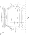
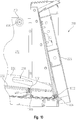
Fig. 1 is a rear view of a vehicle capable of transporting a mobility-challenged individual; -
Fig. 2 is a front perspective view of a ramp system including a ramp in a stowed position for transporting a mobility-challenged individual; -
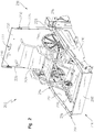
Fig. 3 is a rear perspective view of the ramp system ofFig. 2 with the ramp in a lowered position; -
Fig. 4 is a rear perspective view of the ramp system ofFig. 2 with the ramp in the stowed position; -
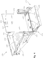
Fig. 5 is another rear perspective view of the ramp system of claim 2 with the ramp in the lowered position; -
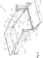
Fig. 6 is a rear perspective view of the ramp system ofFig. 2 with the ramp in a raised position and a rear member in a lowered position; -
Fig. 7 is a rear perspective view of the ramp system ofFig. 2 with the ramp in the raised position and a rear member in a raised position; -
Fig. 8 is a partially exploded, rear perspective view of the ramp system ofFig. 5 ; -
Fig. 9 is a cross-sectional rear perspective view taken along line 9-9 inFig. 5 ; and -
Fig. 10 is a side cross-sectional view of a portion of the ramp system ofFig. 7 . - Corresponding reference numerals are used to indicate corresponding parts throughout the several views.
- The embodiments of the present disclosure described below are not intended to be exhaustive or to limit the disclosure to the precise forms disclosed in the following detailed description. Rather, the embodiments are chosen and described so that others skilled in the art may appreciate and understand the principles and practices of the present disclosure.
- Referring now to
Fig. 1 , avehicle 100 adapted for transporting a mobility-challenged individual is shown. The vehicle can be a van, taxi, bus, or any other type of vehicle capable of transporting a mobility-challenged individual. InFig. 1 , a rear end of thevehicle 100 is shown having apowered lift-gate 102 capable of being electrically, hydraulically, mechanically, or manually raised or lowered. When raised, the lift-gate exposes an access opening 104 to the rear of thevehicle 100. Aramp 106 is shown in a stowed position, i.e., a vertical orientation with respect to a floor of thevehicle 100. The ramp can be used to assist with transporting the mobility-challenged individual from a ground surface to a location inside of the vehicle. - In
Fig. 2 , for example, one embodiment is shown of aramp system 200 capable of being adapted in avehicle 100 similar to the one inFig. 1 . Here, theramp system 200 includes aramp 202 disposed in a stowed or vertical position. In this position, theramp system 200 is capable of stowing awheelchair 206, for example. To do so, theramp system 200 may include a partial enclosure orframe 204 that includes at least afront member 208 disposed towards afront 216 of theramp system 200, arear member 228 disposed towards the rear 218 thereof, and afirst side member 210 and asecond side member 212. Thefirst side member 210 andsecond side member 212 may each be coupled to thefront member 208 andrear member 228 to form theframe 204. Theframe 204 forms a cage-like structure that surrounds thewheelchair 206 when disposed inside of thevehicle 100. - Each of the
front member 208,first side member 210,second side member 212, andrear member 228 can be formed of a robust material such as steel to offer protection to the wheelchair and, when occupied, to the occupant. Each member can further include a flange 522 (Fig. 5 ) that defines atop surface 214 as shown inFig. 2 . In some embodiments, the vehicle floor may be redesigned to a location beneath its conventional location, i.e., the floor level is lowered, so that a space is provided for theramp system 200 to occupy inside the vehicle. In this embodiment, thetop surface 214 of each of thefront member 208,first side member 210,second side member 212, andrear member 228 can be arranged substantially parallel or aligned with the conventional floor level inside the vehicle. With the vehicle floor being lowered to a new location, sufficient clearance is provided in the vehicle so that an occupant sitting in thewheelchair 206 can do so comfortably. - As also shown, the
ramp 202 of theramp system 200 is shown in the vertical or stowed position. Theramp 202 can include afirst side panel 224 and asecond side panel 226. Each side panel extends in an approximately 90° angle with respect to aramp surface 302 of theramp 202. As such, the side panels offer side support to theramp 202 when awheelchair 206 is being moved on and off theramp 202. - The
ramp 202 can also include amain handle 222 defined within itsmain surface 302 for use to manually manipulate theramp 202 between positions. In addition, each of thefirst side panel 224 and thesecond side panel 226 may include aside handle 230 as well. While there are several handles depicted in the embodiment ofFig. 2 , it is to be understood that in alternative embodiments theramp 202 may be controlled electronically or otherwise such that the handles are unnecessary to manipulate theramp 202. Moreover, in other embodiments, theramp 202 may be manipulated manually or automatically, i.e., there may be automatic means in the form of an electronic, hydraulic, mechanical, etc. mechanism to control positioning of theramp 202. - Referring to the embodiments of
Figs. 3-7 , theramp system 202 is capable of being maneuvered in a plurality of orientations or positions. InFig. 3 , for example, theramp 202 is disposed in a loweredposition 300. Here, theramp 202 may be pivoted about apivot pin 304 that defines a pivot axis from the stowed position ofFig. 2 to the loweredposition 300 ofFig. 3 . Thepivot pin 304 is shown in greater detail inFig. 8 and will be described below. - In the lowered
position 300, theramp 202 can be configured at an angle with respect to a floor or pan 220 of theenclosure 204. As described above, theframe 204 includes thefront member 208,first side member 210,second side member 212, andrear member 228 to partially surround or enclose thewheelchair 206 in the stowed position. In this position, theramp 202 may be disposed in its loweredposition 300 so that thewheelchair 206 may be moved along theramp surface 302 and into the interior of thevehicle 100. As thewheelchair 206 enters the interior of thevehicle 100, it may be rolled or moved onto thefloor 220 of theenclosure 204. Thefloor 220 of theenclosure 204 may be in contact with the lowered vehicle floor (not shown). This, of course, is only the case when the vehicle floor is lowered from its conventional floor level. In those embodiments in which the vehicle floor is not lowered, thefloor 220 may be in contact and rest above the vehicle floor at the conventional floor level. - Referring to
Fig. 5 , thepan 220 may be formed by a plurality of plates. For instance, thepan 220 may include afirst plate 504, asecond plate 506, and athird plate 508. Each plate may be secured or coupled to the vehicle floor via rivets orother fasteners 510. In other embodiments, there may be additional or fewer plates that form thepan 220. The inclusion of two or more plates allows thepan 220 to take the shape of an uneven surface. For instance, some of the mechanical components of the vehicle such as the driveline, rear axle, engine, transmission, exhaust system, etc. may require the vehicle floor to be uneven, i.e., unparallel from front to rear of the vehicle. The additional plates form thepan 220 to take shape of this lowered floor of the vehicle. - As also shown in the illustrated embodiment of
Fig. 3 , thefirst side panel 224 may include afirst latch member 306. Likewise, thesecond side panel 226 may include asecond latch member 308. Each latch member may be positioned along the respective side panel at a location between thepivot pin 304 and theside handle 230. In addition, each latch member may be structured to define an opening for receiving apin 310 when theramp 202 is moved to the stowed position. In other words, thefirst latch member 306 may define an opening 514 (seeFig. 5 ) for receiving onepin 310 and thesecond latch member 308 may define adifferent opening 516 for receiving anotherpin 310. In this embodiment, onepin 310 is coupled to thefirst side member 210 and theother pin 310 is coupled to thesecond side member 212. Both pins 310 are coupled to the respective side member towards the rear thereof, and at a location that is approximately vertically aligned with thepivot pin 304 of theramp 202. - In the lowered
position 300, theramp 202 may be pivoted about itspivot pin 304 so that thefirst latch member 306 comes into contact with onepin 310 and thesecond latch member 308 comes into contact with theother pin 310. As shown, each latch member can form or define the respective opening therein by a pair of fingers that are structured like pinchers or claws. Thus, as the latch member comes into contact with thepin 310, theramp 202 is pivoted about itspivot pin 304 an additional amount until thepin 310 becomes disposed within the respective opening. In this manner, the structure or design of each latch is such that when thepin 310 is engaged by each latch member, i.e., disposed within the opening formed by the latch member, the latch member partly surrounds thepin 310 to hold or maintain theramp 202 in the stowed position. In other words, an additional force may be required to position thepin 310 within the respective opening formed by each of thefirst latch member 306 and thesecond latch member 308. - Referring to
Fig. 4 , theramp 202 is disposed in its stowedposition 400. As previously described, theramp 202 includes aramp surface 302. On the opposite side as theramp surface 302, theramp 202 may include an underneathsurface 408 upon which one ormore pads 402 are coupled. Thepads 402 may be formed of an elastic material or a plastic. Other materials are also possible for thepads 402. Thepads 402 may protrude from the underneathsurface 408 when theramp 202 is in its loweredposition 300 so that eachpad 402 contacts a ground surface. In this manner, thepads 402 offer support to theramp 202. Thepads 402 may be secured to theramp 202 via one or more fasteners 512 (seeFig. 5 ). - In
Fig. 4 , therear member 228 is shown being positioned in an open position. Therear member 228 is capable of moving between this open position and a closed position, e.g., seeFig. 7 . Theramp 202 andrear member 228 are independently coupled to theramp system 200, and thus each is capable of being moved independently from the other. When the rear member is in the open position, for example, it is possible to maneuver or position theramp 202 in any one of three positions. For instance, theramp 202 may be disposed in a raised or stored position 600 (i.e., seeFig. 6 ), the lowered or deployed position 300 (i.e., seeFigs. 3 and5 ), and the stowed position 400 (i.e., seeFig. 4 ). In the closed position, however, theramp 202 can only be maneuvered or positioned in its raised position or stowed position, i.e., theramp 202 cannot be moved to its lowered or deployed position with therear member 228 in the closed position. - The
rear member 228 can pivot about apivot point 406 as shown inFig. 4 . Moreover, therear member 228 may be coupled to thefloor 220 of theenclosure 204 via a plurality ofhinges 404 to allow for the pivotal movement. Thepivot point 406 of therear member 228 may be different from thepivot pin 304 of theramp 202, such that theramp 202 andrear member 228 are independent from one another. In other words, therear member 228 may be pivoted between its open and closed position independently from theramp 202, and similarly theramp 202 may be pivoted between its raised position, lowered position, and stowed position independently of therear member 228. This may be possible with theramp 202 andrear member 228 not being coupled directly to one another. In many conventional ramp systems, a conventional ramp is directly coupled to a rear tailgate structure such that both pivot in unison with one another. - Referring now to
Fig. 5 , the ramp system is shown with theramp 202 in its loweredposition 300 and therear member 228 in its open position. In order to reach its lowered position, theramp 202 can be in a sliding engagement or slidably coupled to a track system. As shown, a longitudinally-extendingtrack 500 is coupled to thesecond side member 212. Likewise, another track (not shown) is coupled to thefirst side member 210 in a way such that bothtracks 500 are in approximate alignment with one another. - Each
track 500 defines aguide channel 502. Theguide channel 502 includes afirst end 518 and asecond end 520. Thefirst end 518 may be positioned near afront 216 of theramp system 200, whereas thesecond end 520 may be positioned near a rear 218 thereof. Theramp 202 may move through theguide channel 502 between thefirst end 518 and thesecond end 520, such that at thefirst end 518 theramp 202 is disposed in its raised position and at thesecond end 520 theramp 202 is disposed at its lowered position. This is further shown inFigs. 8 and9 . - In
Fig. 8 , for example, the manner in which thesecond side panel 226 of theramp 202 is coupled to thetrack 500 is shown. Here, thesecond side panel 226 includes acurved end 836 this is located at or near the pivot location of theramp 202. As described above, theramp 202 may pivot about apivot pin 304. InFig. 8 , thepivot pin 304 is shown as being formed by apin 816 that is inserted through a correspondingly definedhole 818 in thecurved end 836 of theside panel 226. Thehole 818 is shaped as a key-like slot capable of receiving a key 830. The key 830 protrudes from acap 828 that is positioned on a side opposite thetrack 500 from theside panel 226. Thecap 828 has an annular cross-section as shown inFig. 9 . Moreover, the key 830 includes a threaded opening which may receive thepin 816 in a threaded engagement. - In this embodiment, a washer or
bushing 820 may be positioned between an outer wall of theside panel 226 and an inner wall of thetrack 500. Thepin 816 may pass through thehole 818 defined in theside panel 226 and a corresponding opening defined in the washer orbushing 820. In addition, the key 830 may pass through an opening defined in a second washer orbushing 826. The second washer orbushing 826 may be positioned in contact with an outer wall of thetrack 500. As shown best inFig. 9 , the key 830 may pass through theguide channel 502 for coupling to thepin 816. As such, thepin 816 may be tightened in threaded engagement with the key 830. The engagement of the key 830 and pin 816 may move or slide within theguide channel 502 between itsfirst end 518 and itssecond end 520 to allow theramp 202 to move between its raised and lowered positions. - In the lowered position, the
cap 828 may be received within anopening 834 defined within acoupler 832. Thecoupler 832 includes a main body with a through-hole defined therein. A screw orother fastener 822 may pass through acorresponding opening 824 in thetrack 500 and be coupled to thecoupler 832 via the through-hole. For example, the screw orfastener 822 may be threadedly engaged with the through-hole in thecoupler 832 to secure thecoupler 832 and track 500 to one another. As also shown, thesecond side member 212 may include an opening or through-hole 808 for receiving the screw orfastener 822 as well. Thus, thetrack 500 andcoupler 832 may be coupled to thesecond side member 212. - At the opposite end of the
track 500, i.e., near the front 216 orfirst end 518 of theguide channel 502, anothercoupler 806 may be provided. Thiscoupler 806 may be shaped similarly to thecoupler 832 previously described, i.e., having anopening 810 capable of receiving thecap 828. A screw orfastener 802 may secure thetrack 500 via anopening 804 andcoupler 806 to thesecond side member 212 viahole 808 as shown. Thesecond side member 212 may include a plurality ofholes 808 such that thetrack 500 may be secured at two or more locations along its longitudinal length. InFig. 8 , for example, another screw orfastener 812 is shown capable of being inserted through ahole 814 defined in thetrack 500 at some location between the two ends thereof. The screw orfastener 812 may be coupled to one of the plurality ofholes 808 in thesecond side member 212 as shown. - Referring to the
cross-section 900 ofFig. 9 , thepin 816 is shown being coupled to the key 830 andcap 828. Thepin 816 is positioned within theguide channel 502 at a location between the first and second ends. In the location shown inFig. 9 , thecap 828 is coupled or "snapped" into engagement with thesecond coupler 832. - Each of the
first coupler 806 andsecond coupler 832 are structurally designed to include an opening or open end capable of receiving thecap 828. In the raised position, theramp 202 can be pushed toward thefront 816 of thevehicle 100 until thecap 828 enters and is received in theopen end 810 of thefirst coupler 806. In one example, the engagement between thefirst coupler 806 and thecap 828 may be a snap-fit engagement. Once engaged, theramp 202 may rotate or pivot about itspivot location 304, but thecoupler 806 is capable of retaining thecap 828 from sliding or moving within theguide channel 502. - Likewise, the
second coupler 832 is structured similar to thefirst coupler 806 for receiving thecap 828. Thesecond coupler 832 also includes an open end or opening 834 for receiving thecap 828. An engagement between thecap 828 andsecond coupler 832 may be a snap-fit engagement, for example. Other types of engagement between thecap 828 and the first and second couplers is also possible, e.g., a latching engagement between a slide-bolt and latch opening. In any event, theramp 202 may freely rotate or pivot about thepivot location 304 while retained or coupled to the first and second couplers. Moreover, when thecap 828 is coupled to thesecond coupler 832, theramp 202 may be pivoted between its stowed position and lowered position. Theramp 202 may not pivot any further than its stowed position due to the engagement of the first andsecond latch members pins 310. As shown further inFig. 8 , eachpin 310 may be coupled to its respective side member via a screw, bolt, orother fastener 800. - While the embodiments of
Figs. 5-8 only show onetrack 500 coupled to thesecond side member 212, asimilar track 500 is coupled to thefirst side member 210. Afirst coupler 806 and asecond coupler 832 may also be coupled to thefirst side member 210 as well to enable theramp 202 to move within theguide channels 502 of bothtracks 500 in a sliding manner. - As shown in
Fig. 10 , theramp 202 is configured in its raised position and therear member 828 is disposed in its closed position. Here, a cross-section of theaforementioned pad 402 is shown. Thepad 402 can be fastened to theramp 202 via a screw orfastener 512 as previously described. Thepad 402 can isolate theramp 202 from thepan 220 to thereby reduce rattle or other noise during vehicle operation. In some embodiments, thepad 402 may also contact the ground surface when the ramp is disposed in its lowered position, although this is not the case in all embodiments. - As also shown, a wheelchair tie down
restraint 1000 may be provided. A rear belt retractor may couple to therestraint 1000. In some embodiments, this may not be present. A rearweather strip seal 1002 is also shown inFig. 10 . This feature may be optional in some embodiments. - The
ramp system 200 described above and shown in the accompanying drawings provides for a less complicated mechanism than other conventional ramp systems. In addition, thisramp system 200 allows for additional storage space when the ramp system is designed for a rear or side access to a vehicle. While the accompanying drawings illustrate theramp system 200 for a rear access vehicle, it is within the scope of this disclosure that theramp system 200 may be designed for a side access vehicle as well. - In any event, luggage and other items may be stowed in the rear or side of the vehicle, and the
ramp 202 does not obstruct or prevent items from being stowed as in many conventional ramp systems. Moreover, theramp 202 is capable of being retracted from its raised position to its lowered position, or pivoted between its lowered and stowed positions in an easier manner than many conventional ramp systems. Theramp system 200 is coupled to the vehicle, but theramp 202 is independent from therear member 228. Thus, theramp 202 is easy to maneuver between positions as needed. - The
ramp system 200 may be welded or otherwise coupled to the vehicle to add rigidity and security to the overall system. In some embodiments, the vehicle floor may be dropped or lowered by up to 14" from its conventional floor level in order to accommodate theramp system 200. - In some embodiments, a latching mechanism in the form of a slide bolt may be used to secure the
ramp 202 in the stowed position rather than the engagement of the latch members and pins 310. One skilled in the art may appreciate other mechanisms that can be used to secure or couple theramp 202 in the stowed position. - Attached hereto is an Appendix which includes additional features and embodiments of the present disclosure. Among these features is a slotted opening formed in the
tracks 500 to allow theramp 202 to be removably coupled thereto. The slotted opening may be angled and a top portion of the coupler may limit movement of theramp 202 out of engagement with the track. Thus, theramp 202 may be shifted laterally or lifted at an angle to become disengaged from thetrack 500 via the slotted opening. - While exemplary embodiments incorporating the principles of the present disclosure have been disclosed hereinabove, the present disclosure is not limited to the disclosed embodiments, Further, this application is intended to cover such departures from the present disclosure as come within known or customary practice in the art to which this disclosure pertains and which fall within the limits of the appended claims.
Claims (14)
- A retractable ramp system (200), comprising:a frame (204) including a front member (208), a first side member (210), a second side member (212), a rear member (228), and a frame floor (220), the rear member (228) being pivotally coupled to the frame (204) so that the rear member (228) is pivotal between an open position and a closed position;a first track (500) coupled to the first side member (210) and defining a first longitudinal channel (502) therein, the first longitudinal channel (502) of the first track (500) includes a first end (518) and a second end, the first end (518) being positioned longitudinally between the front member (208) of the frame (204) and the second end (520);a second track (500) coupled to the second side member (212) and defining a second longitudinal channel (502) therein, the second longitudinal channel (502) of the second track (500) including a first end (518) and a second end (520), the first end (518) being positioned longitudinally between the front member (208) of the frame (204) and the second end (520);a ramp (202) pivotably coupled to the first and second tracks (500) about a pivot axis, the ramp (202) including a ramp floor (302), a first side panel (224), and a second side panel (226) and a pivot pin (304) defining the pivot axis about which the ramp (202) is pivoted;characterised in that a first latch member (306; 308) is coupled to the first side panel (224) and a second latch member (308) is coupled to the second side panel (212); anda pin (310) is coupled to one of the first side member (210) and the second side member (212);wherein, the ramp (202) is movable between (i) a raised position, (ii) a lowered position, and (iii) a stowed position, wherein the pivot pin (304) is slidably coupled to slide within and along one of the longitudinal channels (502) of the first track (500) and the second track (500) wherein the ramp (202) pivots about the pivot pin (304) at the second end (520) while the pivot pin (304) is located in one of the longitudinal channels (502) when the ramp (202) is pivoted from the lowered position to the stowed position to engage the pin (310) with one of the first latch member (306) and the second latch member (308);further wherein, one of the first latch member (306) and the second latch member (308) is coupled to the pin (310) in the stowed position.
- The system (200) of claim 1, wherein the pin (310) comprises a first pin coupled to the first side member (210) and a second pin coupled to the second side member (212).
- The system (200) of claim 2, wherein the latch member (306; 308) includes a first latch member (306) coupled to the first pin and a second latch member (308) coupled to the second pin in the stowed position.
- The system (200) of claim 1, further comprising:a cap (828) including an annular body, and a key (830) protruding from the annular body;wherein, the pivot pin (304) is received within an opening defined in the key (830) such that the ramp (202) is pivotable about the pivot pin (304) and key (830).
- The system (200) of claim 4, further comprising a coupler (832) coupled to one of the first track (500) and second track, the coupler (832) having an open end (834) for receiving the annular body of the cap (828).
- The system (200) of claim 5, wherein the coupler (832) comprises a first coupler (832) and a second coupler (806), the first coupler (832) being coupled to one end of the respective track (500) and the second coupler (806) being coupled to an opposite end thereof.
- The system (200) of claim 5, wherein a movement of the ramp (202) is restricted to a pivotal movement only when the cap (828) is coupled to the coupler (832).
- The system (200) of claim 1, wherein the ramp (202) is independent from the rear member (228).
- The system (200) of claim 1, wherein the ramp (202) is disposable in the lowered position only when the rear member (228) is in the open position.
- The system (200) of claim 1, further comprising a slotted opening defined in the first track (500) and second track, wherein the ramp (202) is removably engaged from the first and second tracks (500) via the slotted opening.
- The system (200) of claim 1, further comprising one or more pads (402) coupled to the ramp (202).
- The system (200) of claim 1, wherein the frame floor (220) comprises at least a first portion (504) and a second portion (506), the first and second portions configured to be coupled to a floor of a vehicle (100).
- The system (200) of claim 3, wherein the ramp (202) in the stowed position is located between the rear member (228) and the first pin and the second pin.
- The system (200) of claim 13 wherein each of the first latch members (306) defines a first opening (514) and the second latch members (308) defines a second opening (516), wherein each of the first opening (514) and second opening (516) are configured to respectively receive the first pin and the second pin in the stowed position.
Applications Claiming Priority (2)
| Application Number | Priority Date | Filing Date | Title |
|---|---|---|---|
| US201462082385P | 2014-11-20 | 2014-11-20 | |
| PCT/US2015/060297 WO2016081268A1 (en) | 2014-11-20 | 2015-11-12 | Retractable ramp system for motorized vehicle |
Publications (3)
| Publication Number | Publication Date |
|---|---|
| EP3220868A1 EP3220868A1 (en) | 2017-09-27 |
| EP3220868A4 EP3220868A4 (en) | 2018-06-20 |
| EP3220868B1 true EP3220868B1 (en) | 2021-01-06 |
Family
ID=56014398
Family Applications (1)
| Application Number | Title | Priority Date | Filing Date |
|---|---|---|---|
| EP15860309.2A Active EP3220868B1 (en) | 2014-11-20 | 2015-11-12 | Retractable ramp system for motorized vehicle |
Country Status (4)
| Country | Link |
|---|---|
| US (1) | US10470950B2 (en) |
| EP (1) | EP3220868B1 (en) |
| CA (1) | CA2964788A1 (en) |
| WO (1) | WO2016081268A1 (en) |
Families Citing this family (6)
| Publication number | Priority date | Publication date | Assignee | Title |
|---|---|---|---|---|
| US10010461B2 (en) | 2015-02-25 | 2018-07-03 | All-Terrain Conversions, Llc | Lift mechanism for wheelchairs in vehicles |
| US11926201B1 (en) * | 2018-02-27 | 2024-03-12 | Michael A. Lillo | School bus emergency egress system |
| US10568786B1 (en) | 2018-09-25 | 2020-02-25 | Creative Carriage Ltd. | Pivotal handle for folding a ramp of a vehicle |
| US10821038B2 (en) * | 2018-10-26 | 2020-11-03 | Freedom Motors, Inc. | Ramp system for a motorized vehicle |
| US11349269B2 (en) | 2020-06-25 | 2022-05-31 | Aaron Werner | Wireless adapter and handheld electronic device to wirelessly control the wireless adapter |
| US11865903B2 (en) | 2021-05-24 | 2024-01-09 | The Braun Corporation | Articulating anti-rattle device for a ramp |
Family Cites Families (19)
| Publication number | Priority date | Publication date | Assignee | Title |
|---|---|---|---|---|
| US2543471A (en) * | 1946-12-27 | 1951-02-27 | James L Scholl | Mechanical device for teaching harmonica playing |
| US2997665A (en) * | 1959-07-22 | 1961-08-22 | Gen Electric | Multivibrator circuit having a bistable circuit driving and triggered by a relaxation circuit |
| US5971465A (en) * | 1998-03-02 | 1999-10-26 | Ives; Michael | Tailgate ramp system |
| JP2002306535A (en) * | 2001-04-10 | 2002-10-22 | Nissan Techno Co Ltd | Self-traveling vehicle for wheelchair |
| US6802095B1 (en) * | 2002-01-25 | 2004-10-12 | Ricon Corporation | Ramp assembly having a lift and lock mechanism |
| US7527467B2 (en) * | 2003-01-29 | 2009-05-05 | The Braun Corporation | Retractable ramp system for a mobility vehicle |
| US7326024B2 (en) * | 2003-02-19 | 2008-02-05 | Lift-U, Division Of Hogan Mfg., Inc. | Wheelchair lift assembly having a compact stowed profile |
| US20050179269A1 (en) * | 2004-02-12 | 2005-08-18 | Vantage Mobility International, Llc | Gated rear entry for wheelchair |
| US20050280274A1 (en) * | 2004-06-16 | 2005-12-22 | Devitt Jon W | Trailer tailgate |
| US7458624B1 (en) * | 2007-05-16 | 2008-12-02 | Trailgate Tailgate Systems, Inc. | Tailgate and ramp for pickup truck |
| US20090044729A1 (en) * | 2007-08-16 | 2009-02-19 | Shape Corporation | Multi-functional running board and ramp apparatus |
| CZ18846U1 (en) | 2008-07-08 | 2008-08-28 | Api Cz S.R.O. | Tiltable drive-up ramp for driving wheelchair with passenger in a vehicle |
| US20120009050A1 (en) * | 2010-07-09 | 2012-01-12 | Pepin Donald M | Off-road vehicle loading/unloading device supported by trailer hitch |
| US8659883B2 (en) * | 2011-12-02 | 2014-02-25 | Shenzhen China Star Optoelectronics Technology Co., Ltd. | Liquid crystal display device with connector |
| JP5765241B2 (en) * | 2012-01-10 | 2015-08-19 | トヨタ車体株式会社 | Slope device for vehicle |
| FR2997665B1 (en) * | 2012-11-06 | 2016-11-04 | Renault Tech | ASSEMBLY FORMING ACCESS RAMP FOR PERSONS WITH REDUCED MOBILITY AND VEHICLE THUS EQUIPPED |
| DE202013002152U1 (en) * | 2013-03-07 | 2014-06-11 | Amf-Bruns Gmbh & Co. Kg | Ramp system for installation in a vehicle |
| US9597240B2 (en) * | 2013-05-30 | 2017-03-21 | The Braun Corporation | Vehicle accessibility system |
| GB2543471A (en) * | 2014-12-11 | 2017-04-26 | Sirus Automotive Ltd | Improvements in or relating to control mechanisms for vehicle access ramps |
-
2015
- 2015-11-12 EP EP15860309.2A patent/EP3220868B1/en active Active
- 2015-11-12 CA CA2964788A patent/CA2964788A1/en active Pending
- 2015-11-12 WO PCT/US2015/060297 patent/WO2016081268A1/en active Application Filing
-
2017
- 2017-04-13 US US15/486,509 patent/US10470950B2/en active Active
Non-Patent Citations (1)
| Title |
|---|
| None * |
Also Published As
| Publication number | Publication date |
|---|---|
| EP3220868A4 (en) | 2018-06-20 |
| US10470950B2 (en) | 2019-11-12 |
| CA2964788A1 (en) | 2016-05-26 |
| EP3220868A1 (en) | 2017-09-27 |
| US20170216113A1 (en) | 2017-08-03 |
| WO2016081268A1 (en) | 2016-05-26 |
Similar Documents
| Publication | Publication Date | Title |
|---|---|---|
| EP3220868B1 (en) | Retractable ramp system for motorized vehicle | |
| US9597240B2 (en) | Vehicle accessibility system | |
| US9302718B2 (en) | Truck bed door with optional extension and accessories | |
| EP1813455A2 (en) | Vehicle with an entrance aid | |
| EP4051587B1 (en) | An aircraft passenger accommodation unit | |
| US20090102216A1 (en) | Multi-Functional Vehicle Tailgate | |
| US20230181393A1 (en) | Manually foldable wheelchair ramp | |
| CA2633558A1 (en) | Liftgate column cover and service access | |
| US9555696B2 (en) | Apparatus and method for distributing a tarp over a cargo on a truck load bed | |
| EP1363804B1 (en) | Sheltered aircraft supply vehicle | |
| EP2212201B1 (en) | A liftable vehicle | |
| US10017978B2 (en) | Methods and apparatus for overriding powered vehicle door | |
| US8783754B1 (en) | Vehicle having utility bed and retractable seat | |
| US11732512B2 (en) | Remotely locked airline overhead bins | |
| US20150375668A1 (en) | Commercial vehicle having a modular body | |
| AU2008202212A1 (en) | Vehicle mounted, wheelchair boarding apparatus | |
| GB2386351A (en) | A vehicle having a movable partition | |
| EP2933192A1 (en) | A loading platform for a service vehicle | |
| US20140159409A1 (en) | Truck bed to passenger compartment integrating mechanism in double cab pickup trucks | |
| GB2598335A (en) | Vehicle ramp assembly | |
| WO2024015482A1 (en) | Methods, systems, and devices for a door for a vehicle | |
| EP2201920B1 (en) | Transportation vehicle provided with access means for persons with reduced mobility | |
| JP2004268763A (en) | Rain guard |
Legal Events
| Date | Code | Title | Description |
|---|---|---|---|
| STAA | Information on the status of an ep patent application or granted ep patent |
Free format text: STATUS: THE INTERNATIONAL PUBLICATION HAS BEEN MADE |
|
| PUAI | Public reference made under article 153(3) epc to a published international application that has entered the european phase |
Free format text: ORIGINAL CODE: 0009012 |
|
| STAA | Information on the status of an ep patent application or granted ep patent |
Free format text: STATUS: REQUEST FOR EXAMINATION WAS MADE |
|
| 17P | Request for examination filed |
Effective date: 20170502 |
|
| AK | Designated contracting states |
Kind code of ref document: A1 Designated state(s): AL AT BE BG CH CY CZ DE DK EE ES FI FR GB GR HR HU IE IS IT LI LT LU LV MC MK MT NL NO PL PT RO RS SE SI SK SM TR |
|
| AX | Request for extension of the european patent |
Extension state: BA ME |
|
| DAV | Request for validation of the european patent (deleted) | ||
| DAX | Request for extension of the european patent (deleted) | ||
| A4 | Supplementary search report drawn up and despatched |
Effective date: 20180524 |
|
| RIC1 | Information provided on ipc code assigned before grant |
Ipc: A61G 3/06 20060101AFI20180517BHEP |
|
| STAA | Information on the status of an ep patent application or granted ep patent |
Free format text: STATUS: EXAMINATION IS IN PROGRESS |
|
| 17Q | First examination report despatched |
Effective date: 20190819 |
|
| GRAP | Despatch of communication of intention to grant a patent |
Free format text: ORIGINAL CODE: EPIDOSNIGR1 |
|
| STAA | Information on the status of an ep patent application or granted ep patent |
Free format text: STATUS: GRANT OF PATENT IS INTENDED |
|
| INTG | Intention to grant announced |
Effective date: 20200605 |
|
| GRAS | Grant fee paid |
Free format text: ORIGINAL CODE: EPIDOSNIGR3 |
|
| GRAA | (expected) grant |
Free format text: ORIGINAL CODE: 0009210 |
|
| STAA | Information on the status of an ep patent application or granted ep patent |
Free format text: STATUS: THE PATENT HAS BEEN GRANTED |
|
| AK | Designated contracting states |
Kind code of ref document: B1 Designated state(s): AL AT BE BG CH CY CZ DE DK EE ES FI FR GB GR HR HU IE IS IT LI LT LU LV MC MK MT NL NO PL PT RO RS SE SI SK SM TR |
|
| REG | Reference to a national code |
Ref country code: GB Ref legal event code: FG4D |
|
| REG | Reference to a national code |
Ref country code: AT Ref legal event code: REF Ref document number: 1351546 Country of ref document: AT Kind code of ref document: T Effective date: 20210115 Ref country code: CH Ref legal event code: EP |
|
| REG | Reference to a national code |
Ref country code: DE Ref legal event code: R096 Ref document number: 602015064573 Country of ref document: DE |
|
| REG | Reference to a national code |
Ref country code: IE Ref legal event code: FG4D |
|
| REG | Reference to a national code |
Ref country code: SE Ref legal event code: TRGR |
|
| REG | Reference to a national code |
Ref country code: NL Ref legal event code: MP Effective date: 20210106 |
|
| REG | Reference to a national code |
Ref country code: AT Ref legal event code: MK05 Ref document number: 1351546 Country of ref document: AT Kind code of ref document: T Effective date: 20210106 |
|
| REG | Reference to a national code |
Ref country code: LT Ref legal event code: MG9D |
|
| PG25 | Lapsed in a contracting state [announced via postgrant information from national office to epo] |
Ref country code: PT Free format text: LAPSE BECAUSE OF FAILURE TO SUBMIT A TRANSLATION OF THE DESCRIPTION OR TO PAY THE FEE WITHIN THE PRESCRIBED TIME-LIMIT Effective date: 20210506 Ref country code: NO Free format text: LAPSE BECAUSE OF FAILURE TO SUBMIT A TRANSLATION OF THE DESCRIPTION OR TO PAY THE FEE WITHIN THE PRESCRIBED TIME-LIMIT Effective date: 20210406 Ref country code: GR Free format text: LAPSE BECAUSE OF FAILURE TO SUBMIT A TRANSLATION OF THE DESCRIPTION OR TO PAY THE FEE WITHIN THE PRESCRIBED TIME-LIMIT Effective date: 20210407 Ref country code: HR Free format text: LAPSE BECAUSE OF FAILURE TO SUBMIT A TRANSLATION OF THE DESCRIPTION OR TO PAY THE FEE WITHIN THE PRESCRIBED TIME-LIMIT Effective date: 20210106 Ref country code: FI Free format text: LAPSE BECAUSE OF FAILURE TO SUBMIT A TRANSLATION OF THE DESCRIPTION OR TO PAY THE FEE WITHIN THE PRESCRIBED TIME-LIMIT Effective date: 20210106 Ref country code: LT Free format text: LAPSE BECAUSE OF FAILURE TO SUBMIT A TRANSLATION OF THE DESCRIPTION OR TO PAY THE FEE WITHIN THE PRESCRIBED TIME-LIMIT Effective date: 20210106 Ref country code: BG Free format text: LAPSE BECAUSE OF FAILURE TO SUBMIT A TRANSLATION OF THE DESCRIPTION OR TO PAY THE FEE WITHIN THE PRESCRIBED TIME-LIMIT Effective date: 20210406 |
|
| PG25 | Lapsed in a contracting state [announced via postgrant information from national office to epo] |
Ref country code: LV Free format text: LAPSE BECAUSE OF FAILURE TO SUBMIT A TRANSLATION OF THE DESCRIPTION OR TO PAY THE FEE WITHIN THE PRESCRIBED TIME-LIMIT Effective date: 20210106 Ref country code: PL Free format text: LAPSE BECAUSE OF FAILURE TO SUBMIT A TRANSLATION OF THE DESCRIPTION OR TO PAY THE FEE WITHIN THE PRESCRIBED TIME-LIMIT Effective date: 20210106 Ref country code: RS Free format text: LAPSE BECAUSE OF FAILURE TO SUBMIT A TRANSLATION OF THE DESCRIPTION OR TO PAY THE FEE WITHIN THE PRESCRIBED TIME-LIMIT Effective date: 20210106 Ref country code: AT Free format text: LAPSE BECAUSE OF FAILURE TO SUBMIT A TRANSLATION OF THE DESCRIPTION OR TO PAY THE FEE WITHIN THE PRESCRIBED TIME-LIMIT Effective date: 20210106 |
|
| PG25 | Lapsed in a contracting state [announced via postgrant information from national office to epo] |
Ref country code: IS Free format text: LAPSE BECAUSE OF FAILURE TO SUBMIT A TRANSLATION OF THE DESCRIPTION OR TO PAY THE FEE WITHIN THE PRESCRIBED TIME-LIMIT Effective date: 20210506 |
|
| REG | Reference to a national code |
Ref country code: DE Ref legal event code: R097 Ref document number: 602015064573 Country of ref document: DE |
|
| PG25 | Lapsed in a contracting state [announced via postgrant information from national office to epo] |
Ref country code: CZ Free format text: LAPSE BECAUSE OF FAILURE TO SUBMIT A TRANSLATION OF THE DESCRIPTION OR TO PAY THE FEE WITHIN THE PRESCRIBED TIME-LIMIT Effective date: 20210106 Ref country code: EE Free format text: LAPSE BECAUSE OF FAILURE TO SUBMIT A TRANSLATION OF THE DESCRIPTION OR TO PAY THE FEE WITHIN THE PRESCRIBED TIME-LIMIT Effective date: 20210106 Ref country code: SM Free format text: LAPSE BECAUSE OF FAILURE TO SUBMIT A TRANSLATION OF THE DESCRIPTION OR TO PAY THE FEE WITHIN THE PRESCRIBED TIME-LIMIT Effective date: 20210106 |
|
| PLBE | No opposition filed within time limit |
Free format text: ORIGINAL CODE: 0009261 |
|
| STAA | Information on the status of an ep patent application or granted ep patent |
Free format text: STATUS: NO OPPOSITION FILED WITHIN TIME LIMIT |
|
| PG25 | Lapsed in a contracting state [announced via postgrant information from national office to epo] |
Ref country code: DK Free format text: LAPSE BECAUSE OF FAILURE TO SUBMIT A TRANSLATION OF THE DESCRIPTION OR TO PAY THE FEE WITHIN THE PRESCRIBED TIME-LIMIT Effective date: 20210106 Ref country code: SK Free format text: LAPSE BECAUSE OF FAILURE TO SUBMIT A TRANSLATION OF THE DESCRIPTION OR TO PAY THE FEE WITHIN THE PRESCRIBED TIME-LIMIT Effective date: 20210106 Ref country code: RO Free format text: LAPSE BECAUSE OF FAILURE TO SUBMIT A TRANSLATION OF THE DESCRIPTION OR TO PAY THE FEE WITHIN THE PRESCRIBED TIME-LIMIT Effective date: 20210106 |
|
| 26N | No opposition filed |
Effective date: 20211007 |
|
| PG25 | Lapsed in a contracting state [announced via postgrant information from national office to epo] |
Ref country code: AL Free format text: LAPSE BECAUSE OF FAILURE TO SUBMIT A TRANSLATION OF THE DESCRIPTION OR TO PAY THE FEE WITHIN THE PRESCRIBED TIME-LIMIT Effective date: 20210106 Ref country code: ES Free format text: LAPSE BECAUSE OF FAILURE TO SUBMIT A TRANSLATION OF THE DESCRIPTION OR TO PAY THE FEE WITHIN THE PRESCRIBED TIME-LIMIT Effective date: 20210106 |
|
| PG25 | Lapsed in a contracting state [announced via postgrant information from national office to epo] |
Ref country code: SI Free format text: LAPSE BECAUSE OF FAILURE TO SUBMIT A TRANSLATION OF THE DESCRIPTION OR TO PAY THE FEE WITHIN THE PRESCRIBED TIME-LIMIT Effective date: 20210106 |
|
| PG25 | Lapsed in a contracting state [announced via postgrant information from national office to epo] |
Ref country code: IT Free format text: LAPSE BECAUSE OF FAILURE TO SUBMIT A TRANSLATION OF THE DESCRIPTION OR TO PAY THE FEE WITHIN THE PRESCRIBED TIME-LIMIT Effective date: 20210106 |
|
| PG25 | Lapsed in a contracting state [announced via postgrant information from national office to epo] |
Ref country code: IS Free format text: LAPSE BECAUSE OF FAILURE TO SUBMIT A TRANSLATION OF THE DESCRIPTION OR TO PAY THE FEE WITHIN THE PRESCRIBED TIME-LIMIT Effective date: 20210506 |
|
| PG25 | Lapsed in a contracting state [announced via postgrant information from national office to epo] |
Ref country code: MC Free format text: LAPSE BECAUSE OF FAILURE TO SUBMIT A TRANSLATION OF THE DESCRIPTION OR TO PAY THE FEE WITHIN THE PRESCRIBED TIME-LIMIT Effective date: 20210106 |
|
| REG | Reference to a national code |
Ref country code: CH Ref legal event code: PL |
|
| PG25 | Lapsed in a contracting state [announced via postgrant information from national office to epo] |
Ref country code: LU Free format text: LAPSE BECAUSE OF NON-PAYMENT OF DUE FEES Effective date: 20211112 Ref country code: BE Free format text: LAPSE BECAUSE OF NON-PAYMENT OF DUE FEES Effective date: 20211130 |
|
| REG | Reference to a national code |
Ref country code: BE Ref legal event code: MM Effective date: 20211130 |
|
| PG25 | Lapsed in a contracting state [announced via postgrant information from national office to epo] |
Ref country code: IE Free format text: LAPSE BECAUSE OF NON-PAYMENT OF DUE FEES Effective date: 20211112 |
|
| PG25 | Lapsed in a contracting state [announced via postgrant information from national office to epo] |
Ref country code: FR Free format text: LAPSE BECAUSE OF NON-PAYMENT OF DUE FEES Effective date: 20211130 |
|
| PG25 | Lapsed in a contracting state [announced via postgrant information from national office to epo] |
Ref country code: HU Free format text: LAPSE BECAUSE OF FAILURE TO SUBMIT A TRANSLATION OF THE DESCRIPTION OR TO PAY THE FEE WITHIN THE PRESCRIBED TIME-LIMIT; INVALID AB INITIO Effective date: 20151112 |
|
| PG25 | Lapsed in a contracting state [announced via postgrant information from national office to epo] |
Ref country code: NL Free format text: LAPSE BECAUSE OF NON-PAYMENT OF DUE FEES Effective date: 20210206 Ref country code: CY Free format text: LAPSE BECAUSE OF FAILURE TO SUBMIT A TRANSLATION OF THE DESCRIPTION OR TO PAY THE FEE WITHIN THE PRESCRIBED TIME-LIMIT Effective date: 20210106 |
|
| PG25 | Lapsed in a contracting state [announced via postgrant information from national office to epo] |
Ref country code: LI Free format text: LAPSE BECAUSE OF NON-PAYMENT OF DUE FEES Effective date: 20220630 Ref country code: CH Free format text: LAPSE BECAUSE OF NON-PAYMENT OF DUE FEES Effective date: 20220630 |
|
| PGFP | Annual fee paid to national office [announced via postgrant information from national office to epo] |
Ref country code: GB Payment date: 20231121 Year of fee payment: 9 |
|
| PGFP | Annual fee paid to national office [announced via postgrant information from national office to epo] |
Ref country code: SE Payment date: 20231123 Year of fee payment: 9 Ref country code: DE Payment date: 20231127 Year of fee payment: 9 |