EP3220803B1 - Device for measuring the brain activity signals of an individual - Google Patents
Device for measuring the brain activity signals of an individual Download PDFInfo
- Publication number
- EP3220803B1 EP3220803B1 EP15804902.3A EP15804902A EP3220803B1 EP 3220803 B1 EP3220803 B1 EP 3220803B1 EP 15804902 A EP15804902 A EP 15804902A EP 3220803 B1 EP3220803 B1 EP 3220803B1
- Authority
- EP
- European Patent Office
- Prior art keywords
- sensor
- support
- intended
- supports
- sensors
- Prior art date
- Legal status (The legal status is an assumption and is not a legal conclusion. Google has not performed a legal analysis and makes no representation as to the accuracy of the status listed.)
- Active
Links
- 230000007177 brain activity Effects 0.000 title claims description 7
- 229920001971 elastomer Polymers 0.000 claims description 16
- 238000000537 electroencephalography Methods 0.000 claims description 16
- 238000004497 NIR spectroscopy Methods 0.000 claims description 15
- 239000000463 material Substances 0.000 claims description 15
- 238000005259 measurement Methods 0.000 claims description 14
- 230000003287 optical effect Effects 0.000 claims description 8
- 230000006835 compression Effects 0.000 claims description 7
- 238000007906 compression Methods 0.000 claims description 7
- 210000003625 skull Anatomy 0.000 claims description 7
- 239000000806 elastomer Substances 0.000 claims description 6
- 239000004744 fabric Substances 0.000 claims description 6
- 230000000284 resting effect Effects 0.000 claims 1
- 210000003128 head Anatomy 0.000 description 53
- 229920001296 polysiloxane Polymers 0.000 description 8
- 210000004556 brain Anatomy 0.000 description 4
- 230000000670 limiting effect Effects 0.000 description 4
- 239000004033 plastic Substances 0.000 description 4
- 238000004611 spectroscopical analysis Methods 0.000 description 4
- 238000001320 near-infrared absorption spectroscopy Methods 0.000 description 3
- 239000004753 textile Substances 0.000 description 3
- 241000287107 Passer Species 0.000 description 2
- 241001080024 Telles Species 0.000 description 2
- 238000012550 audit Methods 0.000 description 2
- 230000003416 augmentation Effects 0.000 description 2
- 230000002490 cerebral effect Effects 0.000 description 2
- 230000000694 effects Effects 0.000 description 2
- 230000000004 hemodynamic effect Effects 0.000 description 2
- 238000002347 injection Methods 0.000 description 2
- 239000007924 injection Substances 0.000 description 2
- 239000013307 optical fiber Substances 0.000 description 2
- 230000002787 reinforcement Effects 0.000 description 2
- 210000004761 scalp Anatomy 0.000 description 2
- 239000004743 Polypropylene Substances 0.000 description 1
- 239000000470 constituent Substances 0.000 description 1
- 230000003247 decreasing effect Effects 0.000 description 1
- 210000005069 ears Anatomy 0.000 description 1
- 239000013013 elastic material Substances 0.000 description 1
- 229940082150 encore Drugs 0.000 description 1
- 238000003780 insertion Methods 0.000 description 1
- 230000037431 insertion Effects 0.000 description 1
- 238000009434 installation Methods 0.000 description 1
- 229920000126 latex Polymers 0.000 description 1
- 239000004816 latex Substances 0.000 description 1
- 238000012423 maintenance Methods 0.000 description 1
- 239000002184 metal Substances 0.000 description 1
- 238000000465 moulding Methods 0.000 description 1
- 230000036963 noncompetitive effect Effects 0.000 description 1
- 230000036961 partial effect Effects 0.000 description 1
- -1 polypropylene Polymers 0.000 description 1
- 229920001155 polypropylene Polymers 0.000 description 1
- 235000020004 porter Nutrition 0.000 description 1
- 210000003660 reticulum Anatomy 0.000 description 1
- 230000035900 sweating Effects 0.000 description 1
- 210000001519 tissue Anatomy 0.000 description 1
- 230000000287 tissue oxygenation Effects 0.000 description 1
Images


Classifications
-
- A—HUMAN NECESSITIES
- A61—MEDICAL OR VETERINARY SCIENCE; HYGIENE
- A61B—DIAGNOSIS; SURGERY; IDENTIFICATION
- A61B5/00—Measuring for diagnostic purposes; Identification of persons
- A61B5/24—Detecting, measuring or recording bioelectric or biomagnetic signals of the body or parts thereof
- A61B5/316—Modalities, i.e. specific diagnostic methods
- A61B5/369—Electroencephalography [EEG]
-
- A—HUMAN NECESSITIES
- A61—MEDICAL OR VETERINARY SCIENCE; HYGIENE
- A61B—DIAGNOSIS; SURGERY; IDENTIFICATION
- A61B5/00—Measuring for diagnostic purposes; Identification of persons
- A61B5/68—Arrangements of detecting, measuring or recording means, e.g. sensors, in relation to patient
- A61B5/6801—Arrangements of detecting, measuring or recording means, e.g. sensors, in relation to patient specially adapted to be attached to or worn on the body surface
- A61B5/6802—Sensor mounted on worn items
- A61B5/6803—Head-worn items, e.g. helmets, masks, headphones or goggles
-
- A—HUMAN NECESSITIES
- A61—MEDICAL OR VETERINARY SCIENCE; HYGIENE
- A61B—DIAGNOSIS; SURGERY; IDENTIFICATION
- A61B5/00—Measuring for diagnostic purposes; Identification of persons
- A61B5/0059—Measuring for diagnostic purposes; Identification of persons using light, e.g. diagnosis by transillumination, diascopy, fluorescence
- A61B5/0075—Measuring for diagnostic purposes; Identification of persons using light, e.g. diagnosis by transillumination, diascopy, fluorescence by spectroscopy, i.e. measuring spectra, e.g. Raman spectroscopy, infrared absorption spectroscopy
-
- A—HUMAN NECESSITIES
- A61—MEDICAL OR VETERINARY SCIENCE; HYGIENE
- A61B—DIAGNOSIS; SURGERY; IDENTIFICATION
- A61B5/00—Measuring for diagnostic purposes; Identification of persons
- A61B5/02—Detecting, measuring or recording pulse, heart rate, blood pressure or blood flow; Combined pulse/heart-rate/blood pressure determination; Evaluating a cardiovascular condition not otherwise provided for, e.g. using combinations of techniques provided for in this group with electrocardiography or electroauscultation; Heart catheters for measuring blood pressure
- A61B5/026—Measuring blood flow
- A61B5/0261—Measuring blood flow using optical means, e.g. infrared light
-
- A—HUMAN NECESSITIES
- A61—MEDICAL OR VETERINARY SCIENCE; HYGIENE
- A61B—DIAGNOSIS; SURGERY; IDENTIFICATION
- A61B5/00—Measuring for diagnostic purposes; Identification of persons
- A61B5/145—Measuring characteristics of blood in vivo, e.g. gas concentration, pH value; Measuring characteristics of body fluids or tissues, e.g. interstitial fluid, cerebral tissue
- A61B5/1455—Measuring characteristics of blood in vivo, e.g. gas concentration, pH value; Measuring characteristics of body fluids or tissues, e.g. interstitial fluid, cerebral tissue using optical sensors, e.g. spectral photometrical oximeters
- A61B5/14551—Measuring characteristics of blood in vivo, e.g. gas concentration, pH value; Measuring characteristics of body fluids or tissues, e.g. interstitial fluid, cerebral tissue using optical sensors, e.g. spectral photometrical oximeters for measuring blood gases
- A61B5/14553—Measuring characteristics of blood in vivo, e.g. gas concentration, pH value; Measuring characteristics of body fluids or tissues, e.g. interstitial fluid, cerebral tissue using optical sensors, e.g. spectral photometrical oximeters for measuring blood gases specially adapted for cerebral tissue
-
- A—HUMAN NECESSITIES
- A61—MEDICAL OR VETERINARY SCIENCE; HYGIENE
- A61B—DIAGNOSIS; SURGERY; IDENTIFICATION
- A61B5/00—Measuring for diagnostic purposes; Identification of persons
- A61B5/24—Detecting, measuring or recording bioelectric or biomagnetic signals of the body or parts thereof
- A61B5/25—Bioelectric electrodes therefor
- A61B5/279—Bioelectric electrodes therefor specially adapted for particular uses
- A61B5/291—Bioelectric electrodes therefor specially adapted for particular uses for electroencephalography [EEG]
-
- G—PHYSICS
- G06—COMPUTING; CALCULATING OR COUNTING
- G06F—ELECTRIC DIGITAL DATA PROCESSING
- G06F3/00—Input arrangements for transferring data to be processed into a form capable of being handled by the computer; Output arrangements for transferring data from processing unit to output unit, e.g. interface arrangements
- G06F3/01—Input arrangements or combined input and output arrangements for interaction between user and computer
- G06F3/011—Arrangements for interaction with the human body, e.g. for user immersion in virtual reality
- G06F3/015—Input arrangements based on nervous system activity detection, e.g. brain waves [EEG] detection, electromyograms [EMG] detection, electrodermal response detection
-
- A—HUMAN NECESSITIES
- A61—MEDICAL OR VETERINARY SCIENCE; HYGIENE
- A61B—DIAGNOSIS; SURGERY; IDENTIFICATION
- A61B2562/00—Details of sensors; Constructional details of sensor housings or probes; Accessories for sensors
- A61B2562/02—Details of sensors specially adapted for in-vivo measurements
- A61B2562/0233—Special features of optical sensors or probes classified in A61B5/00
- A61B2562/0238—Optical sensor arrangements for performing transmission measurements on body tissue
-
- A—HUMAN NECESSITIES
- A61—MEDICAL OR VETERINARY SCIENCE; HYGIENE
- A61B—DIAGNOSIS; SURGERY; IDENTIFICATION
- A61B5/00—Measuring for diagnostic purposes; Identification of persons
- A61B5/68—Arrangements of detecting, measuring or recording means, e.g. sensors, in relation to patient
- A61B5/6801—Arrangements of detecting, measuring or recording means, e.g. sensors, in relation to patient specially adapted to be attached to or worn on the body surface
- A61B5/6843—Monitoring or controlling sensor contact pressure
Definitions
- the present invention relates to a device for measuring signals of brain activity, able to be positioned on the head of an individual.
- the device will find a particular application for measuring, on the one hand, by electroencephalography the electrical activity of the brain, and on the other hand, by spectroscopy in the near infrared, data relating to the hydrodynamic conditions of the circulation in the brain, such as than tissue oxygenation.
- Electroencephalographic devices with electrodes which allow the acquisition of an electroencephalogram, that is to say the recording in the form of a signal of the electrical activity of the brain.
- These devices use sensors constituting electrical electrodes that are arranged on the head of individuals to diagnose or explore through helmets or caps, usually called “Helmet ElectroEncephaloGraphy” (or EEG headphones).
- helmets or caps usually called “Helmet ElectroEncephaloGraphy” (or EEG headphones).
- Such cloth hats have been marketed under the brand name "Easycap”.
- Fabric helmets have the disadvantage of not being able to easily handle the individual's hair which disturbs the near-infrared spectroscopy acquisition signals. Indeed, the hair must be removed from the measuring field.
- IRIS Near Infrared Spectroscopy
- NIRS near-infrared spectroscopy
- the sensors used being optical detectors (optical fibers, photodiodes) or emitters (Optical Fiber LEDs) of photons, also called “optodes”.
- these devices are equipped with electrodes only, and designed only to perform an electroencephalogram, or alternatively equipped with emitters and optical detectors and designed to perform near infrared spectroscopy. In other words, these dedicated devices do not allow the simultaneous measurement of signals by electroencephalography and by near-infrared spectroscopy.
- the fabric helmets designed for the electrodes are too flexible to correctly allow the arrangement with respect to the surface of the head of the optodes whose too heavy supports induce deformation of the tissue.
- These loose cloth helmets prevent keeping a provision of optodes strictly perpendicular to the skull of the individual, and this throughout the duration of registration.
- such flexible helmets do not allow to obtain a precise spatial resolution and a reliable measurement of signals of electrical and hemodynamic activities of cerebral origin.
- the locations of the nodes are pre-established and do not always allow the proper positioning of sensors and electrodes according to the head of the individual.
- the elastic straps promote sweating and can cause too much application pressure on the head, especially an infant.
- NR Sign Inc. is still known to have an "EEG" helmet (http://www.nrsign.com/eeg-cap/) whose helmet structure includes two frames connected by a chin strap. These two frames are intended to be arranged on either side of the head, respectively at least locally below the ears.
- a set of elastic silicone son connect the two frames bypassing the head from above, the son extending laterally to the head, and spaced apart from each other. Once put in tension between the two armatures, each silicone wire makes it possible to maintain an electrode support, pinched elastically between the head of the individual and the silicone thread, the silicone thread then in simple support on the support of electrode .
- Such a device has the advantage of allowing a precise (continuous) adjustment of the electrode support along the silicone wire.
- WO2012 / 156643 a device for measuring signals of brain activity to be affixed to the head of an individual, and for simultaneously measuring signals by electroencephalography and by near-infrared spectroscopy, the device having parts for accommodating electrodes , on the one hand, and other parts to accommodate detectors and optical transmitters (optodes), on the other hand.
- the structure of this device comprises a central chain and side chains, each resulting from the assembly of constituent links, in articulation relative to each other.
- Some of the links include the parts adapted to the support of the electrodes, other links of the parts to the support of optodes.
- the invention relates to a device suitable for measuring the signals of the brain activity of an individual, intended to be affixed to the head of said individual having a structure for the port of sensors, said structure allowing a
- said lateral supports are flexible guides, along which said sensor supports (s) are of adjustable positions.
- all or part of the sensor supports are so-called multiple sensor supports, each allowing the support of at least two physically distinct sensors;
- the invention also relates to the use of a device according to the invention equipped with sensors comprising said electrodes for the measurement of signals by electroencephalography and said detectors and optical transmitters for the measurement of signals by spectroscopy in the near infrared, for the simultaneous measurement of said signals by electroencephalography and by near-infrared spectroscopy.
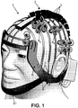
- the invention relates to a device 1 suitable for measuring signals of the brain activity of an individual, intended to be affixed to the head of said individual having a support structure for the port of sensors, said structure allowing adjustment the position of the sensors.
- the flexible guides 3 are distributed on the surface of the head, mutually spaced from each other, according to predefined spacings, in particular by said central support 2. This structure allows, during installation, access to the scalp, and and to release the hair of the sensors positioned by the sensor supports at the different inter-spaces between the flexible guides.
- the sensor supports 4 1 , 4 2 are fixed and integral with said flexible guides 3, but with adjustable positions along these guides. This position adjustment possibility makes it possible in particular to adapt the positions of the different sensors according to the areas of interest to be studied.
- the sensor support (s) 4 1 , 4 2 are integral with the flexible guides 3, and not only in simple support, advantageously allows to perform a pre-assembly of the structure, including a preset positions of different sensors on a manikin head, then remove and affix the structure on the head of the individual, and advantageously without loss of positional adjustments along the flexible guides 3.
- Said system for tensioning said flexible guides may comprise, on the one hand, on each side of the wearer's head, an armature 6, rigid or semi-rigid, intended to extend at least locally under the ear, the two reinforcement 6 being preferably connected by a chin guard 61, and secondly, elastics 5, each secured by one of its ends to the lower end end of a corresponding one of said flexible guides 3, each elastic 5 being intended to be fixed to said frame 6 to ensure the tensioning of the corresponding flexible guide 3.
- the flexible guides 3 and the corresponding elastics 5 are distinct elements: it is thus possible to choose for said flexible guides an inelastic material (for example a conventional textile) in comparison with the material of the elastics 5 which may be of silicone or of another material of the elastomer type.
- the choice of an inelastic material for the flexible guides 3 advantageously makes it possible, when presetting the structure on a manikin head, to ensure that the sensors will, once the structure removed from the manikin and affix on the head of said individual, positioned substantially in the same positions, and without positioning offset as would be encountered in the case where the flexible guides themselves would be in the same material that elastics 5.
- the fact of choosing the flexible guides in an inelastic material (or inextensible) avoids, or at least limit, the reduction phenomena of section of the flexible guides when they are put in tension, reduction of section which, in the case where the flexible guides would be in a elastic material, would cause a loss of position of the sensor supports along the flexible guides.
- each flexible guide 3 and the sensor supports 4 1 , 4 2 are arranged and such that the flexible guides 3 are supported on the head of said individual, in whole or in part, at the length sections of the flexible guide 3 intermediate between the sensor supports 4 1 , 4 2 .
- each flexible guide may take the form of a band, intended to bear on the head, by one of its faces.
- Such a tensioning system also allows adjustment of the tension of each flexible guide 3, by tensioning said corresponding elastic, thus making it possible to constrain on the head all the sensor supports carried by this flexible guide.
- This is advantageously a possibility of continuous adjustment.
- Other embodiments of voltage adjusting means are possible, in particular, discontinuous type settings, for example by providing several attachment positions of the elastic (not shown) on the frame and to allow different tension efforts.
- the frame may be a curved plastic element, as illustrated in FIGS. Figures 13 and 14 , intended to extend, for example, from the back of the head, passing under the ear and to a side area near the front.
- a a plurality of passage openings 7 may allow the insertion of the elastics 5 at the positions most suited to the adjustment.
- this element On the inner side in support with the skin, this element can be covered with a flexible material.
- Position adjustment is advantageously effected without removing the sensor support (s) from its flexible guide, by manually sliding it along the flexible guide 3. Once this manual operation has been performed, that is to say the position of said sensor support (s) set, the holding in position of the sensor support on the flexible guide 3 is advantageously provided (only) by the friction between the flexible guide and the sensor support 41,42.
- said sensor supports 41,42 each include a portion having a foot 46 for pressing on the wearer's head.
- this support foot 46 is preferably at a central position relative to the positions of the various supported sensors.
- This foot may advantageously be a flexible material, different from the body of the support, for example an elastomer.
- said portion of said sensor support having the support foot 46 may comprise two so-called loops 40,41; 42.44; 43,45, positioned on the sensor support, respectively on either side of said foot 46, both crossed by one of the flexible guides 3, and a dorsal surface 47 on which the length section of said guide bears flexible intermediate between the two passers 40,41; 42.44; 43.45.
- the flexible guide 3, in particular the strip passes through a first via 40, from the bottom of the holder 4 1 extends support along the back surface 47, then passes through a second via 41, from the top of support.
- the dorsal surface 47 can be advantageously positioned just above the foot 46, and to increase the stability (tilting) of the sensor support 4 1 , 4 2 .
- all or part of the sensor supports (s) may be sensor supports 4 1 , 4 2 , said multiple, each allowing the support of at least two physically separate sensors.
- the presence of such multiple sensor supports advantageously makes it possible to densify the position of the sensors on an area of interest.
- Said sensor supports may comprise sensor supports 4 1 for two sensors, intended to be positioned on either side of said foot 46 support.
- sensor supports 4 1 for two sensors intended to be positioned on either side of said foot 46 support.
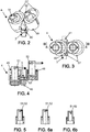
- Such an embodiment is illustrated by way of non-limiting Figures 2 to 4 .
- the foot 46 is positioned halfway between the sensors, which are then positioned on either side of the flexible guide 3 on which said sensor support 41 is secured.
- sensor supports (“double" ) will find particular interest to position sensors on areas of the skull with a strong curvature.
- Sensor supports said multiple, may include sensor supports 4 2 four sensor ( “quad"), to be distributed around said foot support 46.
- the four sensors can be positioned at four corners of a rectangle (for example a square).
- Such an embodiment is illustrated by way of non-limiting Figures 7 to 8 .
- Such an embodiment is particularly interesting in that it makes it possible to group four sensors in close proximity to the same area of interest of the skull, but it nevertheless needs to be applied to a relatively flat skull zone.
- sensor supports double “
- sensor supports quadrature "
- sensor supports quadrature "
- FIG. 1 is a partial figure in that it illustrates only a few sensor supports, the others are not illustrated, for the sake of clarity, to show the structure, and in particular the various flexible guides 3.
- each sensor is designed to be slidably mounted relative to the part of the sensor support equipped with the support foot 46, a spring element 48, such as a compression spring, being configured to force the sensor toward and towards the wearer's head.
- a spring element 48 such as a compression spring
- such an embodiment makes it possible to ensure that the or each sensor is well positioned in bearing on the head of the individual, while controlling the pressure force of said sensor on the head.
- the spring element 48 in particular the compression spring is chosen so that the return force is sufficient to press the sensor on the head, but of sufficiently low stiffness so that this effort is not painful .
- each sensor is movable relative to the portion of the support equipped with the foot 46 and independently from the other sensors.
- Each sensor has an independent spring element 48. As illustrated, not limited to figure 4 (right), the sensor stroke is such that, at the end of the high stroke, it rises substantially above the level of the support of the foot 46.
- the force of the sensor on the head is limited by the choice of the spring element 48, and in particular the choice of its stiffness, and its compression ratio at this position ( prestressing).
- the spring element 48 may have a stiffness of 40 N / m, the prestress defined at 0.25 N when the lower end of the sensor is at the same level as the bearing surface of the foot 46. The structure of the device allows a distribution of the loads decreasing the areas of punctuated pressure.
- said portion of the sensor support (s) equipped with said support foot 46 being called fixed part 49; 50
- said sensor support (s) 4 1 ; 4 2 comprises, for the or each sensor, a movable portion 51, 52; 53, 54, 55, 56 relative to said fixed portion integral with said sensor, said spring member 48 being provided between said fixed portion and said movable portion of said sensor holder.
- said fixed part 49; 50 comprises, for the or each sensor, a hollow configuration, in particular cylindrical, inside which is intended to slide said movable part.
- Said mobile part of the sensor support (s) has a lower end end for fixing a sensor, and a guide surface, in particular cylindrical, intended to slide along the inner wall of the hollow conformation.
- the movable portion 51 or 52 of the sensor support may be specific to a particular type of sensor, thereby acting as an adapter.
- the device can thus comprise a set of moving parts, respectively constituting different adapters for mounting different sensors. physically distinct such as electrodes, or the transmitter or the detector of an optode.
- the moving part of the support shown in figure 5 is an adapter for fixing an electrode, while the moving parts of the figure 6a and some figure 6b respectively allow the mounting of the emitting and detecting part of an optode.
- said movable portion has a projecting portion extending through an upper opening of the hollow conformation, a locking member 57, such as a pin, being removably mounted on the projecting portion, so as, on the one hand, ensure the maintenance and locking of said movable portion 51,52; 53, 54, 55, 56 at said fixed portion 49; 50, said sensor support (s) 4 1 ; 4 2 , and secondly, allow, once the locking member removed, removal and disassembly of the movable portion 51,52; 53, 54, 55, 56 with respect to said fixed portion 49; 50.
- the assembly and disassembly of the locking member 57 is preferably carried out without tools.
- the locking member 57 may advantageously take the form of a loop, intended for gripping, and to move the sensor away from the surface of the head when a traction force is made on the loop.
- the loop is an elastically deformable element, for example metal having two free ends intended to be inserted into two corresponding holes of the projecting portion.
- this locking member 57 once mounted, abuts with the fixed part, at the end of the low stroke, preventing the removal of the mobile part from the hollow conformation of the fixed part.
- the withdrawal of the loop is performed by deforming the loop and so as to leave the free ends of the orifices. Once the loop is removed, the moving part can be extracted from the hollow conformation.
- the fixed part body of the sensor may be a plastic part, in particular injection molded, the foot constituted by an elastomeric element attached to the body.
- each movable portion 51,52; 53, 54, 55, 56 may be a plastic element, especially injection molded.
- Said central support 2 may have, along the length direction, a plurality of transverse passages 20, in particular in the form of grooves, mutually spaced apart. along the length of said central support for the respective positioning and holding of a plurality of flexible guides 3, according to different spacing positions defined between said flexible guides.
- Said central support 2 may have a longitudinal channel 2 in the direction of the length, function of cable-guide, intended for guiding the wire links of the various sensors.
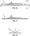
- the central support 2 may be an elastomer element which comprises a central band whose lower surface is intended to bear on the head, and the upper surface is provided with said transverse passages, in over-depth and in the form of grooves, respectively distributed along the band.
- Said central support may have raised edges 22,23, discontinuously, between the grooves, along the two longitudinal edges of the strip and forming, with said central strip, said longitudinal channel 21.
- the central support 2 can be in one elastomer material, and in particular obtained by molding.
- This channel 21 makes it possible to guide the wired links of the sensors towards a box receiving an electronics for acquiring the signals from the sensors, said box being integral with the structure, positioned in the rear part of the head.
- This box internally receives an electronic acquisition of measurement signals, in particular near-infrared spectroscopy signals and / or electroencephalographic signals.
- the device may further comprise a cap (not shown), removable, in a blackout material, intended to be applied to the sensor support structure of the device, and in order to isolate the sensors (in particular the optodes) from the light interference of the ambient environment.
- Such a cap advantageously allows the wearer to proceed to NIRS measurements, in compliance with the recording conditions (that is to say in the dark), and without the need to plunge the wearer in the dark.
- the cap may be in a blackout fabric, light and so as not to press the sensor supports (s), and present a tightening link and / or elastic, around its periphery in order to adjust the cap to different sizes of head.
Description
La présente invention est relative à un dispositif pour la mesure des signaux de l'activité cérébrale, apte à être positionné sur la tête d'un individu.The present invention relates to a device for measuring signals of brain activity, able to be positioned on the head of an individual.
Le dispositif trouvera une application particulière pour mesurer, d'une part, par électroencéphalographie l'activité électrique du cerveau, et d'autre part, par spectroscopie dans le proche infrarouge, des données relatives aux conditions hydrodynamiques de la circulation dans le cerveau, tel que l'oxygénation tissulaire.The device will find a particular application for measuring, on the one hand, by electroencephalography the electrical activity of the brain, and on the other hand, by spectroscopy in the near infrared, data relating to the hydrodynamic conditions of the circulation in the brain, such as than tissue oxygenation.
Il est connu des dispositifs d'électroencéphalographie à électrodes qui permettent l'acquisition d'un électroencéphalogramme, c'est-à-dire l'enregistrement sous la forme d'un signal de l'activité électrique du cerveau. Ces dispositifs utilisent des capteurs constituant des électrodes électriques qui sont disposés sur la tête d'individus à diagnostiquer ou à explorer grâce à des casques ou bonnets, dénommés usuellement « Casque d'ElectroEncéphaloGraphie » (ou casque EEG). De tels bonnets en tissus ont été commercialisés sous la marque « Easycap ».Electroencephalographic devices with electrodes are known which allow the acquisition of an electroencephalogram, that is to say the recording in the form of a signal of the electrical activity of the brain. These devices use sensors constituting electrical electrodes that are arranged on the head of individuals to diagnose or explore through helmets or caps, usually called "Helmet ElectroEncephaloGraphy" (or EEG headphones). Such cloth hats have been marketed under the brand name "Easycap".
Les casques en tissu présentent l'inconvénient de ne pas pouvoir manipuler aisément les cheveux de l'individu qui perturbent les signaux d'acquisition de spectroscopie dans le proche infrarouge. En effet, les cheveux doivent être écartés du champ de mesure.Fabric helmets have the disadvantage of not being able to easily handle the individual's hair which disturbs the near-infrared spectroscopy acquisition signals. Indeed, the hair must be removed from the measuring field.
Par ailleurs, la spectroscopie proche de l'infrarouge (SPIR), dénommée également "NIRS" pour Near-infrared spectroscopy (en anglais) dans des longueurs d'ondes comprises entre 600 et 900 nm, permet de rendre compte de l'activité hémodynamique du cerveau sous forme d'un signal, les capteurs utilisés étant des détecteurs (fibres optiques, photodiodes) ou émetteurs (Fibres optiques LED) optiques de photons, que l'on appelle également " optodes ".In addition, Near Infrared Spectroscopy (IRIS), also known as "NIRS" for near-infrared spectroscopy (in English) in wavelengths between 600 and 900 nm, allows to account for hemodynamic activity. of the brain in the form of a signal, the sensors used being optical detectors (optical fibers, photodiodes) or emitters (Optical Fiber LEDs) of photons, also called "optodes".
Bien souvent, ces dispositifs sont équipés d'électrodes seulement, et conçus seulement pour réaliser un électroencéphalogramme, ou alternativement équipés d'émetteurs et de détecteurs optiques et conçus pour réaliser une spectroscopie proche de l'infrarouge. Autrement dit ces dispositifs dédiés ne permettent pas la mesure simultanée de signaux par électroencéphalographie et par spectroscopie dans le proche infrarouge.Often, these devices are equipped with electrodes only, and designed only to perform an electroencephalogram, or alternatively equipped with emitters and optical detectors and designed to perform near infrared spectroscopy. In other words, these dedicated devices do not allow the simultaneous measurement of signals by electroencephalography and by near-infrared spectroscopy.
Les casques en tissu conçus pour les électrodes sont trop souples pour autoriser correctement l'agencement par rapport à la surface de la tête des optodes dont les supports trop lourds induisent une déformation du tissu. Ces casques en tissu trop lâches empêchent de conserver une disposition des optodes strictement perpendiculaire au crâne de l'individu, et cela durant toute la durée de l'enregistrement. Aussi, de tels casques souples ne permettent pas d'obtenir une résolution spatiale précise et une mesure fiable des signaux des activités électriques et hémodynamique d'origine cérébrale.The fabric helmets designed for the electrodes are too flexible to correctly allow the arrangement with respect to the surface of the head of the optodes whose too heavy supports induce deformation of the tissue. These loose cloth helmets prevent keeping a provision of optodes strictly perpendicular to the skull of the individual, and this throughout the duration of registration. Also, such flexible helmets do not allow to obtain a precise spatial resolution and a reliable measurement of signals of electrical and hemodynamic activities of cerebral origin.
L'état de la technique connait toutefois du document
On connaît des casques plus rigides qui allient le port des électrodes et celui des optodes, dits casques modulaires, tels que ceux commercialisés sous la marque Shimadzu®. Ces casques en matière plastique relativement rigide sont du type polypropylène et couvrent l'ensemble de la tête en étant doté d'une pluralité d'orifices distincts selon le type de capteur à recevoir.There are more rigid helmets that combine the wearing of electrodes and that of optodes, so-called modular headsets, such as those marketed under the trademark Shimadzu®. These relatively rigid plastic helmets are polypropylene type and cover the entire head being provided with a plurality of separate orifices depending on the type of sensor to receive.
Toutefois, l'agencement sur la tête d'une personne des dispositifs décrits ci-dessus n'est pas satisfaisant au regard de la qualité des contacts des dispositifs électriques et optiques du fait des courbures de la tête, des cheveux et du manque de flexibilité du dispositif, en particulier pour les jeunes enfants et les nouveaux nés. On connaît par ailleurs des structures qui ne sont pas des bonnets et qui présentent des bandes ou sangles de latex ou de caoutchouc qui relient entres elles des nœuds formant des supports de capteurs ou électrodes. La structure faite ainsi sous forme de réseau ménage des évidements pour le passage des cheveux. On peut citer par exemple les demandes de brevet
Cependant, les emplacements des nœuds sont pré-établis et ne permettent pas toujours le positionnement idoine des capteurs et des électrodes selon la tête de l'individu. En outre, pour certaines structures, les sangles élastiques favorisent la sudation et peuvent provoquer une pression d'application trop importante sur la tête, en particulier d'un nourrisson.However, the locations of the nodes are pre-established and do not always allow the proper positioning of sensors and electrodes according to the head of the individual. In addition, for some structures, the elastic straps promote sweating and can cause too much application pressure on the head, especially an infant.
On connaît encore de la Société NR Sign Inc. un casque « EEG » (http://www.nrsign.com/eeg-cap/) dont la structure de casque comprend deux armatures reliées par une mentonnière. Ces deux armatures sont destinées à être disposées, de part et d'autre de la tête, respectivement au moins localement en dessous des oreilles. Un ensemble de fils élastiques en silicone, relient les deux armatures en contournant la tête par le dessus, les fils s'étendant latéralement à la tête, et de manière espacée les uns des autres. Une fois mis en tension entre les deux armatures, chaque fil en silicone permet de maintenir un support d'électrode, pincé élastiquement entre la tête de l'individu et le fil silicone, le fil silicone alors en simple appui sur le support d'électrode.NR Sign Inc. is still known to have an "EEG" helmet (http://www.nrsign.com/eeg-cap/) whose helmet structure includes two frames connected by a chin strap. These two frames are intended to be arranged on either side of the head, respectively at least locally below the ears. A set of elastic silicone son, connect the two frames bypassing the head from above, the son extending laterally to the head, and spaced apart from each other. Once put in tension between the two armatures, each silicone wire makes it possible to maintain an electrode support, pinched elastically between the head of the individual and the silicone thread, the silicone thread then in simple support on the support of electrode .
Un tel dispositif présente pour avantage de permettre un réglage précis (continu) du support d'électrode le long du fil silicone.Such a device has the advantage of allowing a precise (continuous) adjustment of the electrode support along the silicone wire.
En revanche, et selon les constatations des inventeurs, un tel casque présente des inconvénients majeurs, et en particulier :
- la conception et l'encombrement des supports de capteur n'autorisent que le positionnement d'un faible nombre d'électrodes EEG sur la tête d'un individu ; un tel dispositif ne permet en aucun cas les positionnements simultanés de capteurs d'électrodes et de capteurs d'optodes, structurellement indépendants, et selon une concentration permettant de cibler des mêmes zones d'intérêt,
- la mise en place d'un tel casque, en particulier le réglage des positions des supports de capteur le long des fils silicones doit obligatoirement se faire directement sur la tête de l'individu : autrement dit, il n'est pas possible de prédisposer les supports de capteur sur une tête de mannequin en ce que, une fois le casque retiré du mannequin, les réglages de positionnement sont perdus.
- the design and size of the sensor supports only allow the positioning of a small number of EEG electrodes on the head of an individual; such a device does not allow in any case the simultaneous positioning of electrode sensors and optodes sensors, structurally independent, and in a concentration to target the same areas of interest,
- the setting up of such a helmet, in particular the adjustment of the positions of the sensor supports along the silicone threads must necessarily be done directly on the head of the individual: in other words, it is not possible to predispose the sensor brackets on a dummy head in that, once the helmet is removed from the manikin, the positioning adjustments are lost.
On connaît encore du document
La structure de ce dispositif comprend une chaîne centrale et des chaînes latérales, chacune résultant de l'assemblage de maillons constitutifs, en articulation les uns par rapport aux autres. Certains des maillons comprennent les pièces adaptées au support des électrodes, d'autres maillons des pièces au support d'optodes.The structure of this device comprises a central chain and side chains, each resulting from the assembly of constituent links, in articulation relative to each other. Some of the links include the parts adapted to the support of the electrodes, other links of the parts to the support of optodes.
Selon les constatations des inventeurs, une telle structure de dispositif présente les inconvénients suivants :
- les chaînes (centrales ou latérales), résultant de l'assemblage de maillons rigides sont à l'origine de douleurs pour l'individu, en ce que les chaînes appuient sur la tête en une pluralité de contacts « durs »,
- une telle structure à maillons permet certes un réglage des positions des capteurs (électrodes ou optodes) en différentes positions de montage possibles sur les maillons. Toutefois, il s'agit seulement d'un réglage de position en plusieurs positions discrètes préétablies, définies par les maillons, et non d'une possibilité de réglage continue le long des chaînes,
- selon les constatations des inventeurs, la concentration des différents capteurs peut encore être améliorée.
- the chains (central or lateral), resulting from the assembly of rigid links are causing pain for the individual, in that the chains rest on the head in a plurality of "hard" contacts,
- such a link structure certainly allows a setting of the sensor positions (electrodes or optodes) in different mounting positions on the links. However, it is only a position adjustment in several pre-established discrete positions, defined by the links, and not a possibility of continuous adjustment along the chains,
- according to the findings of the inventors, the concentration of the various sensors can be further improved.
On connaît du document
La présente invention a pour but de pallier les inconvénients précités en proposant un dispositif pour la mesure de signaux d'activité cérébrale dont la structure autorise, au moins selon des modes de réalisation particuliers:
- l'accès au cuir chevelu et de manière à dégager les cheveux des capteurs en particulier des émetteurs/détecteurs d'optodes, et/ou des électrodes,
- un confort de portage pour l'utilisateur, sans création de pression trop importante à l'origine de douleurs,
- un réglage des positions des différents supports capteur(s), en différentes positions, et de préférence de manière continue le long de guides latéraux,
- de procéder au montage du dispositif, y compris d'effectuer des pré-réglages des positions des différents supports de capteur(s) sur une tête de mannequin, puis de retirer le dispositif ainsi préparé et afin de l'apposer sur la tête d'un individu, avantageusement sans perte des réglages de positionnement,
- de porter un nombre important de capteurs, en particulier des électrodes et des optodes, et selon une densité spatiale permettant l'acquisition simultanée de signaux par électroencéphalographie et par spectroscopie dans le proche infrarouge, sur des zones d'intérêt ciblées.
- access to the scalp and in order to release the hair from the sensors, in particular optode emitters / detectors, and / or electrodes,
- a wearing comfort for the user, without creating too much pressure causing pain,
- a setting of the positions of the different sensor supports (s), in different positions, and preferably in a continuous manner along lateral guides,
- to assemble the device, including pre-adjusting the positions of the various sensor supports on a manikin head, then removing the device thus prepared and affixing it to the head of the device; an individual, advantageously without loss of positioning settings,
- to carry a large number of sensors, in particular electrodes and optodes, and according to a spatial density allowing the simultaneous acquisition of signals by electroencephalography and by near-infrared spectroscopy, on targeted areas of interest.
Aussi l'invention concerne un dispositif convenant pour la mesure des signaux de l'activité cérébrale d'un individu, destiné à être apposé sur la tête dudit individu comportant une structure destinée au port de capteurs, ladite structure autorisant unAlso the invention relates to a device suitable for measuring the signals of the brain activity of an individual, intended to be affixed to the head of said individual having a structure for the port of sensors, said structure allowing a
Selon l'invention, ladite structure du dispositif comporte :
- un support central, de préférence déformable, apte à s'adapter à la courbure de tête, destiné à être positionné le long de la tête, de préférence suivant le plan médian du crâne,
- des supports latéraux, s'étendant latéralement audit support central, espacés les uns des autres,
- des supports de capteur(s), solidaires et fixés auxdits supports latéraux, de positions réglables le long des guides souples,
- un système de mise en tension desdits supports latéraux.
- a central support, preferably deformable, adapted to adapt to the head curvature, intended to be positioned along the head, preferably along the median plane of the skull,
- lateral supports, extending laterally to said central support, spaced from one another,
- sensor supports (s), integral and fixed to said lateral supports, adjustable positions along the flexible guides,
- a system for tensioning said lateral supports.
Selon l'invention lesdits supports latéraux sont des guides souples, le long desquels lesdits supports de capteur(s) sont de positions réglables.According to the invention said lateral supports are flexible guides, along which said sensor supports (s) are of adjustable positions.
Selon l'invention, lesdits supports de capteur(s) sont de positions réglables le long des guides souples, lesdits supports de capteur(s) présentant deux passants pour les guides souples autorisant un tel réglage de position, lesdits supports de capteurs comportant chacun une partie de support présentant :
- un pied, en particulier élastomère, destiné à appuyer sur la tête du porteur, dans une position centrale par rapport aux positions des différents capteurs supportés, les deux dits passants étant positionnés sur le support de capteur, respectivement de part et d'autre dudit pied,
- une surface dorsale sur laquelle appuie la section de longueur dudit guide souple intermédiaire entre les deux passants, ladite surface dorsale étant positionnée juste au-dessus du pied, afin d'augmenter la stabilité du support de capteurs.
- a foot, in particular an elastomer, intended to press on the wearer's head, in a central position with respect to the positions of the various supported sensors, said two loops being positioned on the sensor support, respectively on either side of said foot; ,
- a dorsal surface on which supports the length section of said intermediate flexible guide between the two loops, said dorsal surface being positioned just above the foot, in order to increase the stability of the sensor support.
Selon l'invention, tout ou partie des supports de capteur(s) sont des supports de capteurs dits multiples, permettant chacun le support d'au moins deux capteurs physiquement distincts ;According to the invention, all or part of the sensor supports (s) are so-called multiple sensor supports, each allowing the support of at least two physically distinct sensors;
Selon des caractéristiques optionnelles de l'invention prises seules ou en combinaison :
- ledit système de mise en tension desdits guides souples, comporte, d'une part, de chaque côté de la tête du porteur, une armature, rigide, destinée à s'étendre au moins localement sous l'oreille, les deux armatures étant de préférence reliées par une mentonnière, et d'autre part, des élastiques, chacun solidaire par l'une de ses extrémités à l'extrémité terminale inférieure de l'un correspondant desdits guides souples, chaque élastique étant destiné à être fixé à ladite armature pour assurer la mise en tension du guide souple correspondant ;
- ledit système de mise en tension comporte un moyen de réglage de la tension de l'élastique ;
- le moyen de réglage de la tension de l'élastique comporte une ouverture de passage de l'armature pour l'élastique, ladite ouverture de passage étant dimensionnée inférieure par rapport à la section de l'élastique, et de telle sorte que :
- un effort manuel de traction sur l'extrémité libre de l'élastique permet le glissement de l'élastique au travers de ladite ouverture de passage, et ainsi un réglage par augmentation de la tension, et lorsque l'effort manuel n'est plus,
- les frottements entre l'ouverture de passage et l'élastique sont tels qu'ils interdisent le glissement, assurant la mise en tension du guide souple correspondant ;
- les guides souples sont dans un matériau inélastique ;
- les guides souples sont dans un textile ;
- lesdits guides souples sont des bandes ;
- une fois l'opération manuelle de réglage effectuée, le maintien en position du support de capteurs sur le guide souple est assuré par les frottements entre le guide souple et le support de capteurs ;
- lesdits supports de capteurs, dits multiples, comprennent des supports de capteurs pour deux capteurs, destinés à être positionnés de part et d'autre dudit pied d'appui ;
- lesdits supports de capteurs, dit multiples, comprennent des supports de capteurs pour quatre capteurs, destinés à être répartis autour dudit pied d'appui ;
- chaque capteur est destiné à être monté mobile en coulissement par rapport à la partie du support de capteur équipé du pied d'appui, un élément ressort, tel qu'un ressort de compression, étant configuré pour contraindre le capteur en direction vers et en appui sur la tête de l'individu ;
- ladite partie du support de capteur(s) équipée dudit pied d'appui étant nommée partie fixe, ledit support de capteur(s) comprend, pour le ou chaque capteur, une partie mobile par rapport à ladite partie fixe, sur laquelle est solidarisé le capteur, ledit élément ressort étant prévu entre ladite partie fixe et ladite partie mobile dudit support de capteur(s) ;
- ladite partie fixe comporte, pour le ou chaque capteur, une conformation creuse, en particulier cylindrique, à l'intérieur de laquelle est destinée à glisser ladite partie mobile et dans lequel ladite partie mobile du support de capteur(s) présente une extrémité terminale pour la fixation d'un capteur, ainsi qu'une surface de guidage destinée à coulisser le long de la paroi intérieure de la conformation creuse ;
- ladite partie mobile présente une partie saillante s'étendant au travers d'une ouverture supérieure de la conformation creuse, un organe de verrouillage, tel qu'une goupille, étant monté de manière amovible sur la partie saillante, de manière à, d'une part, assurer le maintien et le verrouillage de ladite partie mobile à ladite partie fixe dudit support de capteur(s) et d'autre part, permettre, une fois l'organe de verrouillage retiré, le retrait et le démontage de la partie mobile par rapport à ladite partie fixe ;
- l'organe de verrouillage prend la forme d'une boucle, destinée à la préhension, et permettant d'écarter le capteur de la surface de la tête lorsqu'un effort de traction est effectué sur la boucle ;
- ledit support central présente, suivant le sens de la longueur, une pluralité de passages transversaux, mutuellement espacés suivant la longueur dudit support central pour le positionnement et le maintien respectif d'une pluralité de guides souples, suivant différentes positions d'écartement définies entre lesdits guides souples ;
- ledit support central, forme suivant le sens de la longueur, un canal longitudinal, à fonction de guide-câbles, destiné pour le guidage des liaisons filaires des différents capteurs ;
- le dispositif comprend un boitier recevant une électronique d'acquisition des signaux des capteurs ;
- le dispositif présente des capteurs comportant des électrodes destinées à la mesure de signaux par électroencéphalographie et/ou des détecteurs et émetteurs optiques pour la mesure de signaux par spectroscopie dans le proche infrarouge ;
- le dispositif comprend une coiffe amovible, en un matériau occultant, destinée à être appliquée sur la structure support de capteurs du dispositif, et de manière à isoler les capteurs des interférences lumineuses de l'environnement ambiant.
- said system for tensioning said flexible guides comprises, on the one hand, on each side of the wearer's head, a rigid reinforcement intended to extend at least locally under the ear, the two armatures being preferably connected by a chin strap, and secondly, elastics, each secured by one of its ends to the lower end end of a corresponding one of said flexible guides, each elastic being intended to be fixed to said frame to ensure tensioning the corresponding flexible guide;
- said tensioning system comprises means for adjusting the tension of the elastic;
- the tension adjusting means of the elastic comprises a passage opening of the armature for the elastic, said passage opening being dimensioned smaller than the section of the elastic, and so that:
- a manual traction force on the free end of the elastic allows the sliding of the elastic through said passage opening, and thus an adjustment by increasing the tension, and when the manual effort is no longer,
- the friction between the passage opening and the elastic are such that they prohibit sliding, ensuring the tensioning of the corresponding flexible guide;
- the flexible guides are in an inelastic material;
- the soft guides are in a textile;
- said flexible guides are strips;
- once the manual adjustment operation has been performed, the positioning of the sensor support on the flexible guide is ensured by the friction between the flexible guide and the sensor support;
- said so-called multiple sensor supports comprise sensor supports for two sensors, intended to be positioned on either side of said support foot;
- said so-called multiple sensor supports comprise sensor supports for four sensors, intended to be distributed around said support foot;
- each sensor is intended to be slidably mounted relative to the portion of the sensor support equipped with the support foot, a spring element, such as a compression spring, being configured to constrain the sensor towards and in support on the head of the individual;
- said portion of the sensor support (s) equipped with said support foot being called fixed part, said sensor support (s) comprises, for the or each sensor, a movable portion with respect to said fixed part, on which is fixed the sensor, said spring member being provided between said fixed portion and said movable portion of said sensor holder (s);
- said fixed part comprises, for the or each sensor, a hollow, in particular cylindrical, configuration inside which is intended to slide said movable part and in which said movable part of the sensor support (s) has a terminal end for attaching a sensor, and a guide surface for sliding along the inner wall of the hollow conformation;
- said movable portion has a projecting portion extending through an upper opening of the hollow conformation, a locking member, such as a pin, being removably mounted on the projecting portion, so as to on the other hand, maintaining and locking said moving part to said fixed part of said sensor support (s) and secondly, allowing, once the locking member has been withdrawn, the removal and disassembly of the mobile part by in relation to said fixed part;
- the locking member takes the form of a loop for gripping, and to move the sensor away from the surface of the head when a pulling force is made on the loop;
- said central support has, along the length direction, a plurality of transverse passages mutually spaced along the length of said central support for the positioning and the respective holding of a plurality of flexible guides, according to different spacing positions defined between said flexible guides;
- said central support, shape in the direction of the length, a longitudinal channel, function of cable-guide, for guiding the wire links of the various sensors;
- the device comprises a housing receiving an electronics for acquiring the signals of the sensors;
- the device has sensors comprising electrodes for the measurement of electroencephalographic signals and / or optical detectors and emitters for the measurement of signals by near-infrared spectroscopy;
- the device comprises a removable cap, in a blackout material, intended to be applied to the sensor support structure of the device, and so as to isolate the sensors from light interference from the ambient environment.
L'invention concerne encore l'utilisation d'un dispositif conforme à l'invention équipé des capteurs comportant lesdites électrodes destinées à la mesure de signaux par électroencéphalographie et lesdits détecteurs et émetteurs optiques pour la mesure de signaux par spectroscopie dans le proche infrarouge, pour la mesure simultanée desdits signaux par électroencéphalographie et par spectroscopie dans le proche infrarouge.The invention also relates to the use of a device according to the invention equipped with sensors comprising said electrodes for the measurement of signals by electroencephalography and said detectors and optical transmitters for the measurement of signals by spectroscopy in the near infrared, for the simultaneous measurement of said signals by electroencephalography and by near-infrared spectroscopy.
L'invention sera mieux comprise à la lecture de la description suivante accompagnée des dessins en annexe parmi lesquels :
- La
figure 1 est une vue en perspective d'un dispositif conforme à l'invention, appliqué sur la tête d'un individu, - Les
figures 2, 3 sont respectivement des vues en perspective, de dessus, une vue de coupe selon la coupe III-III de laet 4figure 3 , d'un support de capteurs, à deux capteurs, - La
figure 5 est une vue de coupe de la partie mobile du support de capteurs, conforme à l'invention selon un mode de réalisation, et convenant à un type de capteur, en particulier une électrode, - La
figure 6a est une vue de coupe de la partie mobile du support de capteurs, conforme à l'invention selon un mode de réalisation, et convenant à un type de capteur, en particulier un émetteur d'une optode, - La
figure 6b est une vue de coupe de la partie mobile du support de capteurs, conforme à l'invention selon un mode de réalisation, et convenant à un type de capteur, en particulier un détecteur d'une optode, - Les
figures 7, 8 et 9 sont respectivement des vues en perspective, de dessus, et de coupe selon la coupe VIII-VIII de lafigure 8 , d'un support de capteurs à quatre capteurs, - Les
figures 10, 11 et 12 , sont respectivement des vues de dessus, de coupe selon la coupe X-X de lafigure 10 , et de face, d'un support central, selon un exemple, - Les
figures 13 et 14 sont des vues de côté et de face de l'armature (droite) du dispositif, - La
figure 15 est une vue éclatée d'un boitier, de son capot, ainsi que d'une carte électronique pour acquisition des signaux de mesure.
- The
figure 1 is a perspective view of a device according to the invention, applied to the head of an individual, - The
Figures 2, 3 and 4 are respectively perspective views, from above, a sectional view according to section III-III of thefigure 3 , a sensor support, with two sensors, - The
figure 5 is a sectional view of the mobile part of the sensor support, according to the invention according to one embodiment, and suitable for a type of sensor, in particular an electrode, - The
figure 6a is a sectional view of the mobile part of the sensor support, according to the invention according to one embodiment, and suitable for a type of sensor, in particular an emitter of an optode, - The
figure 6b is a sectional view of the mobile part of the sensor support, according to the invention according to one embodiment, and suitable for a type of sensor, in particular a detector of an optode, - The
Figures 7, 8 and 9 are respectively views in perspective, from above, and section according to section VIII-VIII of thefigure 8 , a sensor support with four sensors, - The
Figures 10, 11 and 12 are, respectively, top views, of section along the section XX of thefigure 10 , and from the front, of a central support, according to an example, - The
Figures 13 and 14 are side and front views of the armature (right) of the device, - The
figure 15 is an exploded view of a housing, its cover, as well as an electronic card for acquisition of the measurement signals.
Aussi, l'invention concerne un dispositif 1 convenant pour la mesure des signaux de l'activité cérébrale d'un individu, destiné à être apposé sur la tête dudit individu comportant une structure de support destinée au port de capteurs, ladite structure autorisant un réglage de la position des capteurs.Also, the invention relates to a
Selon l'invention, ladite structure du dispositif comporte :
- un support central 2, de préférence déformable, apte à s'adapter à la courbure de tête, destiné à être positionné le long de la tête, de préférence suivant le plan médian du crâne,
- des guides
souples 3, s'étendant latéralement audit support central, en particulier de part et d'autre dudit support central, espacés les uns des autres, - des supports de capteur(s) 41, 42, fixés et solidaires auxdits guides souples, de positions réglables le long des guides,
un système 5, 6 de mise en tension desdits guidessouples 3.
- a
central support 2, preferably deformable, adapted to adapt to the head curvature, intended to be positioned along the head, preferably along the median plane of the skull, -
flexible guides 3, extending laterally to said central support, in particular on either side of said central support, spaced from each other, - sensor supports 4 1 , 4 2 fixed and integral with said flexible guides, with adjustable positions along the guides,
- a
system 5, 6 for tensioning saidflexible guides 3.
Les guides souples 3 sont répartis sur la surface de la tête, mutuellement espacés les uns des autres, selon des écartements prédéfinis, en particulier par ledit support central 2. Cette structure permet, lors de la pose, l'accès au cuir chevelu, et ainsi de dégager les cheveux des capteurs positionnés par les supports de capteurs au niveau des différents inter-espaces entre les guides souples.The
Les supports de capteur(s) 41, 42 sont fixés et solidaires auxdits guides souples 3, mais toutefois de positions réglables le long de ces guides. Cette possibilité de réglage de position permet notamment d'adapter les positions des différents capteurs en fonction des zones d'intérêts à étudier.The sensor supports 4 1 , 4 2 are fixed and integral with said
Le fait que les support de capteur(s) 41, 42 soient solidaires des guides souples 3, et non seulement en simple appui, permet avantageusement d'effectuer un pré-montage de la structure, y compris un préréglage des positions des différents capteurs sur une tête de mannequin, puis de retirer et d'apposer la structure sur la tête de l'individu, et avantageusement sans perte des réglages de position le long des guides souples 3.The fact that the sensor support (s) 4 1 , 4 2 are integral with the
Ledit système de mise en tension desdits guides souples peut comporter, d'une part, de chaque côté de la tête du porteur, une armature 6, rigide ou semi rigide, destinée à s'étendre au moins localement sous l'oreille, les deux armatures 6 étant de préférence reliées par une mentonnière 61, et d'autre part, des élastiques 5, chacun solidaire par l'une de ses extrémités à l'extrémité terminale inférieure de l'un correspondant desdits guides souples 3, chaque élastique 5 étant destiné à être fixé à ladite armature 6 pour assurer la mise en tension du guide souple 3 correspondant.Said system for tensioning said flexible guides may comprise, on the one hand, on each side of the wearer's head, an
On notera que, selon ce mode de réalisation avantageux, les guides souples 3 et les élastiques 5 correspondants sont des éléments distincts : il est ainsi possible de choisir pour lesdits guides souples un matériau inélastique (par exemple un textile classique) par comparaison au matériau des élastiques 5 qui peuvent être en silicone ou dans un autre matériau du type élastomère.It will be noted that, according to this advantageous embodiment, the
Selon les constatations des inventeurs, le choix d'un matériau inélastique pour les guides souples 3 (par comparaison au matériau des élastiques 5), permet avantageusement de garantir, lors d'un préréglage de la structure sur une tête de mannequin, que les capteurs seront, une fois la structure retirée du mannequin et apposer sur la tête dudit individu, positionnés sensiblement en les mêmes positions, et sans décalage de positionnement tels qu'il seraient rencontrés dans le cas où les guides souples seraient eux-mêmes dans le même matériau que les élastiques 5.According to the findings of the inventors, the choice of an inelastic material for the flexible guides 3 (as compared with the material of the elastics 5) advantageously makes it possible, when presetting the structure on a manikin head, to ensure that the sensors will, once the structure removed from the manikin and affix on the head of said individual, positioned substantially in the same positions, and without positioning offset as would be encountered in the case where the flexible guides themselves would be in the same material that elastics 5.
En particulier, et dans le cas où les supports de capteurs 41 ; 42 sont fixés aux guides souples grâce à des passants 40,41 ; 42,44 ; 43,45 des supports, traversés par les guides souples 3, et tels que décrits par la suite, le fait de choisir les guides souples en un matériau inélastique (ou inextensible) permet d'éviter, ou à tout le moins de limiter, les phénomènes de réduction de section des guides souples lorsque ces derniers sont mis en tension, réduction de section qui, dans le cas où les guides souples seraient en un matériau élastique, provoquerait une perte de position des supports de capteurs le long des guides souples.In particular, and in the case where the sensor supports 4 1 ; 4 2 are attached to the flexible guides with
Selon un mode de réalisation, les guides souples 3 et les supports de capteurs 41, 42 sont agencés et tels que les guides souples 3 sont en appui sur la tête dudit individu, en tout ou partie, au niveau des sections de longueur du guide souple 3, intermédiaires, entre les supports de capteurs 41,42. Afin de permettre la stabilité de l'appui du guide souple 3 et une répartition homogène, chaque guide souple peut prendre la forme d'une bande, destinée à venir en appui sur la tête, par l'une de ses faces.According to one embodiment, the
Selon un mode de réalisation ledit système de mise en tension comporte un moyen de réglage de la tension de l'élastique. Par exemple, et tel qu'illustré non limitativement à la
- un effort manuel de traction sur l'extrémité libre de l'élastique 5 permet le glissement de l'élastique au travers de ladite ouverture de
passage 7, et ainsi un réglage par augmentation de la tension, et lorsque l'effort manuel n'est plus, - les frottements entre l'ouverture de
passage 7 et l'élastique 5 sont tels qu'ils interdisent le glissement, assurant la mise en tension du guide souple correspondant.
- a manual tensile force on the free end of the elastic 5 allows the sliding of the elastic through said
passage opening 7, and thus an adjustment by increasing the tension, and when the manual effort is more, - the friction between the
passage opening 7 and the elastic 5 are such that they prevent slippage, ensuring the tensioning of the corresponding flexible guide.
Un tel système de mise en tension permet aussi un réglage de la tension de chaque guide souple 3, par la mise en tension dudit élastique correspondant, permettant ainsi de contraindre sur la tête l'ensemble des supports de capteurs porté par ce guide souple. Il s'agit avantageusement d'une possibilité de réglage continu. D'autres modes de réalisation de moyen de réglage de la tension sont possibles, en particulier, des réglages du type discontinu, par exemple en prévoyant plusieurs positions d'accroche de l'élastique (non illustré) sur l'armature et afin de permettre différents efforts de tension.Such a tensioning system also allows adjustment of the tension of each
L'armature peut être un élément en plastique de forme courbe, tel qu'illustré aux
La possibilité de réglage des supports de capteur(s) 41, 42 le long des guides peut être assurée par des passants 40, 41 ; 42, 43, 44, 45 pour les guides souples autorisant un tel réglage de position. Le réglage de position s'effectue avantageusement, sans retirer le support de capteur(s) de son guide souple, en le faisant glisser manuellement le long du guide souple 3. Une fois cette opération manuelle exécutée, c'est-à-dire la position dudit support de capteur(s) réglée, le maintien en position du support de capteurs sur le guide souple 3 est assuré avantageusement (uniquement) par les frottements entre le guide souple et le support de capteurs 41,42.The possibility of adjusting the sensor supports 41, 42 along the guides can be provided by
Selon un mode de réalisation, lesdits supports de capteurs 41,42 comportent chacun une partie présentant un pied 46 destiné à appuyer sur la tête du porteur. Dans le cas d'un support de capteurs multiple (supportant plusieurs capteurs physiquement distincts), ce pied 46, d'appui est de préférence en une position centrale par rapport aux positions des différents capteurs supportés. Ce pied peut être avantageusement en une matière souple, différente du corps du support, par exemple en un élastomère.According to one embodiment, said sensor supports 41,42 each include a portion having a
Selon un mode de réalisation, ladite partie dudit support de capteurs présentant le pied 46 d'appui peut comprendre deux dits passants 40,41 ; 42,44 ; 43,45 , positionnés sur le support de capteur, respectivement de part et d'autre dudit pied 46, tous deux traversés par l'un des guides souples 3, ainsi qu'une surface dorsale 47 sur laquelle appuie la section de longueur dudit guide souple intermédiaire entre les deux passants 40,41 ; 42,44 ; 43,45.According to one embodiment, said portion of said sensor support having the
Selon ce mode de réalisation, illustré non limitativement, notamment aux
Avantageusement tout ou partie des supports de capteur(s) peuvent être des supports de capteurs 41, 42, dit multiple, permettant chacun le support d'au moins deux capteurs physiquement distincts. La présence de tels supports de capteurs multiples permet avantageusement de densifier la position des capteurs sur une zone d'intérêt.Advantageously all or part of the sensor supports (s) may be sensor supports 4 1 , 4 2 , said multiple, each allowing the support of at least two physically separate sensors. The presence of such multiple sensor supports advantageously makes it possible to densify the position of the sensors on an area of interest.
Lesdits supports de capteurs, dits multiples, peuvent comprendre des supports de capteurs 41 pour deux capteurs, destinés à être positionnés de part et d'autre dudit pied 46 d'appui. Un tel mode de réalisation est illustré à titre non limitatif des
Les supports de capteurs, dit multiple, peuvent comprendre des supports de capteurs 42 pour quatre capteurs (« quadruple »), destinés à être répartis autour dudit pied d'appui 46. Les quatre capteurs peuvent être positionnés aux quatre sommets d'un rectangle (par exemple un carré). Un tel mode de réalisation est illustré à titre non limitatif des
Ainsi et tel qu'illustré à la
Selon un mode de réalisation avantageux, chaque capteur est destiné à être monté mobile en coulissement par rapport à la partie du support de capteurs équipé du pied 46 d'appui, un élément ressort 48, tel qu'un ressort de compression, étant configuré pour contraindre le capteur en direction vers et en appui sur la tête du porteur.According to an advantageous embodiment, each sensor is designed to be slidably mounted relative to the part of the sensor support equipped with the
Avantageusement, un tel mode de réalisation permet de s'assurer que le ou chaque capteur soit bien positionné en appui sur la tête de l'individu, tout en maitrisant l'effort de pression dudit capteur sur la tête.Advantageously, such an embodiment makes it possible to ensure that the or each sensor is well positioned in bearing on the head of the individual, while controlling the pressure force of said sensor on the head.
A cet effet, l'élément ressort 48, notamment le ressort de compression est choisi de manière à ce que l'effort de rappel soit suffisant pour plaquer le capteur sur la tête, mais de raideur suffisamment faible pour que cet effort ne soit pas douloureux. Dans le cas d'un support de capteurs multiples, chaque capteur est mobile par rapport à la partie du support équipé du pied 46 et de manière indépendante par rapport aux autres capteurs. Chaque capteur présente un élément ressort 48, indépendant. Comme illustré non limitativement à la
Selon un mode de réalisation, ladite partie du support de capteur(s) équipée dudit pied d'appui 46 étant nommée partie fixe 49; 50, ledit support de capteur(s) 41; 42 comprend, pour le ou chaque capteur, une partie mobile 51,52 ; 53, 54, 55, 56 par rapport à ladite partie fixe solidaire dudit capteur, ledit élément ressort 48 étant prévu entre ladite partie fixe et ladite partie mobile dudit support de capteurs.According to one embodiment, said portion of the sensor support (s) equipped with said
A cet effet et selon un mode de réalisation illustré, ladite partie fixe 49 ; 50 comporte, pour le ou chaque capteur, une conformation creuse, en particulier cylindrique, à l'intérieur de laquelle est destinée à glisser ladite partie mobile. Ladite partie mobile du support de capteur(s) présente une extrémité terminale, inférieure pour la fixation d'un capteur, ainsi qu'une surface de guidage, notamment cylindrique, destinée à coulisser le long de la paroi intérieure de la conformation creuse.For this purpose and according to an illustrated embodiment, said
Tel qu'illustré aux
Selon un mode de réalisation, ladite partie mobile présente un partie saillante s'étendant au travers d'une ouverture supérieure de la conformation creuse, un organe de verrouillage 57, tel qu'une goupille, étant monté de manière amovible sur la partie saillante, de manière à, d'une part, assurer le maintien et le verrouillage de ladite partie mobile 51,52 ; 53, 54, 55, 56 à ladite partie fixe 49; 50, dudit support de capteur(s) 41; 42, et d'autre part, permettre, une fois l'organe de verrouillage retiré, le retrait et le démontage de la partie mobile 51,52 ; 53, 54, 55, 56 par rapport à ladite partie fixe 49; 50. L'assemblage et le désassemblage de l'organe de verrouillage 57 sont de préférence effectués sans outil.According to one embodiment, said movable portion has a projecting portion extending through an upper opening of the hollow conformation, a locking
L'organe de verrouillage 57 peut avantageusement prendre la forme d'une boucle, destinée à la préhension, et permettant d'écarter le capteur de la surface de la tête lorsqu'un effort de traction est effectué sur la boucle. La boucle est un élément déformable élastiquement, par exemple métallique présentant deux extrémités libres destinées à venir s'insérer dans deux orifices correspondants de la partie saillante.The locking
Tel qu'illustré à la
Le corps de partie fixe du capteur peut être une pièce plastique, notamment moulé par injection, le pied constitué par un élément élastomère rapporté sur le corps. De même, chaque partie mobile 51,52 ; 53, 54, 55, 56 peut être un élément plastique, notamment moulé par injection.The fixed part body of the sensor may be a plastic part, in particular injection molded, the foot constituted by an elastomeric element attached to the body. Similarly, each
Ledit support central 2 peut présenter, suivant le sens de la longueur, une pluralité de passages 20, transversaux, notamment sous la forme de rainures, mutuellement espacés suivant la longueur dudit support central pour les positionnements et les maintiens respectifs d'une pluralité de guides souples 3, suivant différentes positions d'écartement définies entre lesdits guides souples.Said
Ledit support central 2, peut présenter un canal longitudinal 2 suivant le sens de la longueur, à fonction de guide-câbles, destiné pour le guidage des liaisons filaires des différents capteurs. Le support central 2 peut être un élément en élastomère qui comprend une bande centrale, dont la surface inférieure est destinée à prendre appui sur la tête, et la surface supérieure est pourvue desdits passages transversaux, en sur-profondeur et sous la forme de rainures, respectivement réparties le long de la bande. Ledit support central peut présenter des bords relevés 22,23, de manière discontinue, entre les rainures, le long des deux bords longitudinaux de la bande et formant, avec ladite bande centrale, ledit canal longitudinal 21. Le support central 2 peut être en une matière élastomère, et notamment obtenu par moulage.Said
Ce canal 21 permet de guider les liaisons filaires des capteurs en direction d'un boitier recevant une électronique d'acquisition des signaux des capteurs, ledit boitier étant solidaire de la structure, positionné en partie arrière de la tête. Ce boitier reçoit intérieurement une électronique d'acquisition des signaux de mesure, en particulier des signaux par spectroscopie dans le proche infrarouge et/ou des signaux par électroencéphalographie. Dans le cas de la mise en œuvre d'une spectroscopie proche de l'infrarouge, le dispositif peut encore comprendre une coiffe (non illustrée), amovible, en un matériau occultant, destinée à être appliquée sur la structure support de capteurs du dispositif, et de manière à isoler les capteurs (en particulier les optodes) des interférences lumineuses de l'environnement ambiant. Une telle coiffe permet avantageusement au porteur de pouvoir procéder aux mesures NIRS, dans le respect des conditions d'enregistrement (c'est-à-dire dans l'obscurité), et sans nécessiter de plonger le porteur dans l'obscurité. La coiffe peut être dans un tissu occultant, léger et afin de ne pas appuyer sur les supports de capteur(s), et présenter un lien de serrage et/ou un élastique, sur son pourtour afin de pouvoir ajuster la coiffe à différentes tailles de tête.This
- 1. Dispositif,1. Device,
- 2. Support central,2. Central support,
- 3. Guides souples,3. Flexible guides,
- 41, 42. Supports de capteurs (respectivement à deux capteurs ou quatre capteurs),4 1 , 4 2 . Sensor supports (respectively two sensors or four sensors),
- 5. Elastiques,5. Elastics,
- 6. Armatures,6. Armatures,
- 7. Ouvertures de passage (Armatures 6),7. Opening openings (Armatures 6),
- 20. Passages transversaux (Support central 2),20. Cross passages (Central support 2),
- 21. Canal longitudinal (Support central 2),21. Longitudinal channel (Central support 2),
- 22,23. Bords relevés (Support central 2).22.23. Raised edges (Central support 2).
- 40, 41. Passants (Supports capteurs 41),40, 41. Loops (Sensor supports 4 1 ),
- 42, 43, 44, 45. Passants (Supports capteurs 42),42, 43, 44, 45. Loops (Sensor supports 4 2 ),
-
46. Pied (Support de capteurs 41 ou 42),46. Stand (
Sensor support 4 1 or 4 2 ), - 47. Surface dorsale47. Dorsal surface
- 48. Elément ressort (par exemple ressort de compression),48. Spring element (for example compression spring),
- 49. Partie fixe (Supports de capteurs 41),49. Fixed part (Sensor supports 4 1 ),
- 50. Partie fixe (Supports de capteurs 42),50. Fixed part (Sensor supports 4 2 ),
- 51,52. Parties mobiles (Supports de capteurs 41),51.52. Mobile parts (sensor supports 4 1 ),
- 53, 54, 55, 56. Parties mobiles (Supports de capteurs 42),53, 54, 55, 56. Moving parts (sensor supports 4 2 ),
- 57. Organe de verrouillage (notamment boucle de préhension),57. Locking member (in particular a gripping loop),
- 60. Boitier (électronique d'acquisition),60. Case (acquisition electronics),
- 61. Mentonnière.61. Chinrest.
Claims (21)
- A device (1) suitable for measuring brain activity signals of an individual, intended to be placed on the head of said individual including a structure (2) intended for carrying sensors, said structure allowing for an adjustment of the position of the sensors,
wherein said device structure includes :- a central support (2), which is deformable, able to adapt to the head curvature, intended to be positioned along the head, preferably following the median plane of the skull,- lateral supports (3), extending laterally to said central support, spaced from each other,- sensor supports (41, 42), which are integral and fixed to said lateral supports (3), all or part of the sensor supports (41, 42) being so-called multiple sensor supports (41, 42) each allowing for the support of at least two physically distinct sensors,- a system (5, 6) for tensioning said lateral supports (3), where said lateral supports are flexible guides (3), along which the sensor supports (41, 42) have adjustable positions,characterised in that
said sensor supports (41, 42) provide two loop holders (40, 41; 42, 44; 43, 45) for the flexible guides allowing for such position adjustment,
said sensor supports each including a support portion providing:- a foot (46), in particular in elastomer form, intended to press against the wearer's head, in a central position with respect to the positions of the various supported sensors, said two loop holders (40, 41; 42, 44; 43, 45) being positioned on the sensor support, on either side of said foot, respectively,- a back surface (47) on which the length section of said intermediate flexible guide between the two loop holders (40, 41; 42, 44; 43, 45) is resting, said back surface (47) being positionned just over the foot (46), in such a way as to increase the stability of the sensor support (41, 42). - The device according to Claim 1, wherein said system for tensioning said flexible guides includes, on the one hand, on each side of the wearer's head, a rigid armature (6) which is intended to extend at least locally under the ear, the two armatures preferably being connected by a chin strap, and on the other hand, rubber bands (5), which are each secured by one of its ends to the lower terminal end of a corresponding one of said flexible guides (3), each rubber band (5) being intended to be fixed to said armature (6) in order to ensure the tensioning of the corresponding flexible guide (3).
- The device according to Claim 2, wherein said tensioning system includes means for adjusting the tension of the rubber band.
- The device according to Claim 3, wherein the means for adjusting the tension of the rubber band include a passage opening (7) in the armature for the rubber band (5), said passage opening (7) being dimensioned to be smaller than the cross-section of the rubber band (5), and such that:- a manual pulling force on the free end of the rubber band (5) allows the rubber band to slide through said passage opening (7), and thus allows an adjustment by increasing the tension, and when the manual effort is no longer,- the friction between the passage opening (7) and the rubber band (5) is such that it will not allow any sliding, ensuring the tensioning of the corresponding flexible guide.
- The device according to one of Claims 1 to 4 wherein the flexible guides (3) are made of an inelastic material.
- The device according to Claim 5, wherein the flexible guides (3) are in a fabric.
- The device according to one of Claims 1 to 6, wherein said flexible guides (3) are strips.
- The device according to Claim 1, wherein, after the manual adjustment operation has been carried out, maintaining the sensor support in position on the flexible guide is ensured by the friction between the flexible guide (3) and the sensor support (41, 42).
- The device according to one of Claims 1 to 8, wherein said so-called multiple sensor supports comprise sensor supports (41) for two sensors, intended to be positionned on either side of said supporting foot (46).
- The device according to one of Claims 1 to 9, wherein said so-called multiple sensor supports comprise sensor supports (42) for four sensors, intended to be distributed around said supporting foot (46).
- The device according to one of Claims 1 to 10, wherein each sensor is intended to be slidably mounted with respect to the part of the sensor support that is equipped with the supporting foot (46), a spring element (48), such as a compression spring, being configured so as to force the sensor in the direction towards and pressing against the head of the carrier.
- The device according to Claim 11, wherein said part of the sensor support that is equipped with said supporting foot (46) being named fixed part (49; 50), said sensor support (41; 42) comprises, for the sensor or for each sensor, a part (51, 52; 53, 54; 55, 56) which is movable with respect to said fixed part that is integral with said sensor, said spring element (48) being provided between said fixed part and said movable part of said sensor support.
- The device according to Claim 12, wherein said fixed part (49; 50) includes, for the sensor or for each sensor, a hollow, in particular cylindrical, conformation inside which said movable part is intended to slide and in which said movable part of the sensor support has a terminal end for fixing a sensor, as well as a guide surface intended to slide along the inner wall of the hollow conformation.
- The device according to Claim 13, wherein said movable part has a protruding part extending through an upper opening of the hollow conformation, a locking member (57), such as a pin, being removably mounted on the protruding part, so as to, on the one hand, ensure the holding and locking of said movable part (51, 52; 53, 54, 55, 56) to said fixed part (49; 50) of said sensor support (41; 42), and on the other hand, allowing, once the locking member is removed, the removal and disassembling of the movable part (51, 52; 53, 54, 55, 56) with respect to said fixed part (49; 50).
- The device according to Claim 14, wherein the locking member (57) takes the form of a loop, intended for gripping, and allowing the sensor to be separated from the surface of the head when a tensile force is applied to the loop.
- The device according to one of Claims 1 to 15, wherein said central support (2) has, along the lengthwise direction, a plurality of crosswise passageways (20), which are mutually spaced apart along the length of said central support for the respective positioning and holding of a plurality of flexible guides (3), according to different spacing positions defined between said flexible guides.
- The device according to one of Claims 1 to 16, wherein said central support (2) forms a longitudinal channel (21) along the lengthwise direction, with the function of a cable guide, intended for guiding the cable connections of the various sensors.
- The device according to one of Claims 1 to 17, comprising a housing receiving electronics for acquiring sensor signals.
- The device according to one of Claims 1 to 18, wherein the sensors include electrodes which are intended for the measurement of signals by electroencephalography and/or optical detectors and transmitters for the measurement of signals by near infrared spectroscopy.
- The device according to one of Claims 1 to 19 comprising a removable upper cover, made of an occulting material, intended to be applied to the sensor support structure of the device, and in such a way as to isolate the sensors from light interference from the ambient environment.
- A use of a device according to Claim 19 equipped with sensors comprising said electrodes intended for measuring signals by electroencephalography and said optical detectors and transmitters for measuring signals by near infrared spectroscopy, for simultaneous measurement of said signals by electroencephalography and near infrared spectroscopy.
Applications Claiming Priority (2)
| Application Number | Priority Date | Filing Date | Title |
|---|---|---|---|
| FR1461283A FR3028743B1 (en) | 2014-11-21 | 2014-11-21 | DEVICE FOR MEASURING SIGNALS OF THE BRAIN ACTIVITY OF AN INDIVIDUAL |
| PCT/FR2015/053132 WO2016079436A1 (en) | 2014-11-21 | 2015-11-19 | Device for measuring the brain activity signals of an individual |
Publications (2)
| Publication Number | Publication Date |
|---|---|
| EP3220803A1 EP3220803A1 (en) | 2017-09-27 |
| EP3220803B1 true EP3220803B1 (en) | 2019-12-04 |
Family
ID=52807881
Family Applications (1)
| Application Number | Title | Priority Date | Filing Date |
|---|---|---|---|
| EP15804902.3A Active EP3220803B1 (en) | 2014-11-21 | 2015-11-19 | Device for measuring the brain activity signals of an individual |
Country Status (9)
| Country | Link |
|---|---|
| US (1) | US11272880B2 (en) |
| EP (1) | EP3220803B1 (en) |
| JP (1) | JP2018501047A (en) |
| CN (1) | CN107106068B (en) |
| BR (1) | BR112017010538A2 (en) |
| CA (1) | CA2966689C (en) |
| ES (1) | ES2774795T3 (en) |
| FR (1) | FR3028743B1 (en) |
| WO (1) | WO2016079436A1 (en) |
Families Citing this family (39)
| Publication number | Priority date | Publication date | Assignee | Title |
|---|---|---|---|---|
| WO2016110969A1 (en) * | 2015-01-07 | 2016-07-14 | 株式会社日立製作所 | Biophoton measurement device |
| CN106491091B (en) * | 2016-11-28 | 2019-08-23 | 武汉资联虹康科技股份有限公司 | A kind of probe of near infrared spectrum cerebral function imaging device |
| CN107625520B (en) * | 2017-09-25 | 2020-12-18 | 联想(北京)有限公司 | Sign signal detection electrode and intelligent clothing |
| CN108594989B (en) * | 2018-03-26 | 2022-03-22 | Oppo广东移动通信有限公司 | Brain wave acquisition method and related equipment |
| FR3086527B1 (en) * | 2018-10-02 | 2023-01-06 | Urgotech | SENSOR FOR MEASURING BIOLOGICAL POTENTIAL |
| US11642081B2 (en) | 2019-02-01 | 2023-05-09 | X Development Llc | Electrode headset |
| WO2020167086A1 (en) * | 2019-02-15 | 2020-08-20 | 성균관대학교산학협력단 | Head-mounted sensor device for functional near-infrared spectroscope |
| US11583231B2 (en) | 2019-03-06 | 2023-02-21 | X Development Llc | Adjustable electrode headset |
| WO2020236371A1 (en) | 2019-05-21 | 2020-11-26 | Hi Llc | Photodetector architectures for efficient fast-gating |
| US10868207B1 (en) | 2019-06-06 | 2020-12-15 | Hi Llc | Photodetector systems with low-power time-to-digital converter architectures to determine an arrival time of photon at a photodetector based on event detection time window |
| FR3100125B1 (en) * | 2019-08-30 | 2023-05-26 | Commissariat Energie Atomique | Helmet support for magnetoencephalography device |
| KR102330796B1 (en) * | 2019-09-05 | 2021-11-25 | (주)오비이랩 | Method, system and non-transitory computer-readable recording medium for assessment of autoregulation performance based on hemodynamics |
| FR3101533B1 (en) * | 2019-10-07 | 2021-10-29 | Elsa Lyon | Device for collecting electrophysiological signals for the head of an animal |
| US11950879B2 (en) | 2020-02-21 | 2024-04-09 | Hi Llc | Estimation of source-detector separation in an optical measurement system |
| WO2021167877A1 (en) | 2020-02-21 | 2021-08-26 | Hi Llc | Multimodal wearable measurement systems and methods |
| US11630310B2 (en) * | 2020-02-21 | 2023-04-18 | Hi Llc | Wearable devices and wearable assemblies with adjustable positioning for use in an optical measurement system |
| US11771362B2 (en) | 2020-02-21 | 2023-10-03 | Hi Llc | Integrated detector assemblies for a wearable module of an optical measurement system |
| WO2021167890A1 (en) | 2020-02-21 | 2021-08-26 | Hi Llc | Wearable module assemblies for an optical measurement system |
| US11864867B2 (en) | 2020-03-20 | 2024-01-09 | Hi Llc | Control circuit for a light source in an optical measurement system by applying voltage with a first polarity to start an emission of a light pulse and applying voltage with a second polarity to stop the emission of the light pulse |
| WO2021188485A1 (en) | 2020-03-20 | 2021-09-23 | Hi Llc | Maintaining consistent photodetector sensitivity in an optical measurement system |
| US11903676B2 (en) | 2020-03-20 | 2024-02-20 | Hi Llc | Photodetector calibration of an optical measurement system |
| US11245404B2 (en) | 2020-03-20 | 2022-02-08 | Hi Llc | Phase lock loop circuit based signal generation in an optical measurement system |
| US11645483B2 (en) | 2020-03-20 | 2023-05-09 | Hi Llc | Phase lock loop circuit based adjustment of a measurement time window in an optical measurement system |
| US11187575B2 (en) | 2020-03-20 | 2021-11-30 | Hi Llc | High density optical measurement systems with minimal number of light sources |
| US11857348B2 (en) | 2020-03-20 | 2024-01-02 | Hi Llc | Techniques for determining a timing uncertainty of a component of an optical measurement system |
| US11877825B2 (en) | 2020-03-20 | 2024-01-23 | Hi Llc | Device enumeration in an optical measurement system |
| WO2021188487A1 (en) | 2020-03-20 | 2021-09-23 | Hi Llc | Temporal resolution control for temporal point spread function generation in an optical measurement system |
| US11730373B2 (en) | 2020-04-20 | 2023-08-22 | Covidien Lp | Sensor with variable depth interrogation |
| US11941857B2 (en) | 2020-05-26 | 2024-03-26 | Hi Llc | Systems and methods for data representation in an optical measurement system |
| CN111839531A (en) * | 2020-07-22 | 2020-10-30 | 武汉爱可泰思医疗科技有限公司 | Brain detection device |
| US11789533B2 (en) | 2020-09-22 | 2023-10-17 | Hi Llc | Synchronization between brain interface system and extended reality system |
| WO2022150155A1 (en) | 2021-01-06 | 2022-07-14 | Hi Llc | Devices, systems, and methods using wearable time domain-based activity tracker |
| WO2022182526A1 (en) | 2021-02-26 | 2022-09-01 | Hi Llc | Brain activity tracking during electronic gaming |
| US11543885B2 (en) | 2021-05-26 | 2023-01-03 | Hi Llc | Graphical emotion symbol determination based on brain measurement data for use during an electronic messaging session |
| GB2608808B (en) * | 2021-07-12 | 2024-01-03 | Comind Tech Limited | Systems and Methods for Preparing a Neuroimaging System for Neuroimaging and Analysis of a Subject's Brain Tissue |
| CN114533070B (en) * | 2022-01-28 | 2023-11-14 | 季华实验室 | Flexible wearable brain magnetic measurement helmet |
| CN117848554A (en) * | 2022-10-08 | 2024-04-09 | 歌尔科技有限公司 | Head-face wearing pressure measurement equipment and system |
| CN115633970B (en) * | 2022-12-19 | 2023-06-06 | 浙江强脑科技有限公司 | Portable physiological signal monitoring device and physiological signal monitoring method |
| USD991347S1 (en) * | 2023-02-20 | 2023-07-04 | Guoli Ding | Mannequin |
Citations (3)
| Publication number | Priority date | Publication date | Assignee | Title |
|---|---|---|---|---|
| US8019402B1 (en) * | 2004-11-12 | 2011-09-13 | Orbital Research Inc | Electrode harness and method of taking biopotential measurements |
| WO2012156643A1 (en) * | 2011-05-19 | 2012-11-22 | Université de Picardie Jules Verne | Device for measuring brain activity signals |
| US20140276183A1 (en) * | 2013-03-14 | 2014-09-18 | Yakob Badower | Methods and apparatus to gather and analyze electroencephalographic data |
Family Cites Families (28)
| Publication number | Priority date | Publication date | Assignee | Title |
|---|---|---|---|---|
| US3998213A (en) * | 1975-04-08 | 1976-12-21 | Bio-Volt Corporation | Self-adjustable holder for automatically positioning electroencephalographic electrodes |
| FR2627975B1 (en) | 1988-03-07 | 1990-08-24 | Prugne Pascale | JUNCTION PIECE, FOR THE POSITIONING OF ELECTRODES IN THE SOCKET OF AN ELECTRO-ENCEPHALOGRAM |
| AU667199B2 (en) * | 1991-11-08 | 1996-03-14 | Physiometrix, Inc. | EEG headpiece with disposable electrodes and apparatus and system and method for use therewith |
| JP2560155Y2 (en) | 1993-06-24 | 1998-01-21 | セーラー万年筆株式会社 | EEG measurement device |
| US5800351A (en) * | 1996-10-04 | 1998-09-01 | Rest Technologies, Inc. | Electrode supporting head set |
| HRP970562A2 (en) | 1997-11-04 | 2000-10-31 | Pavić Milica | Universal eeg cap |
| US6161030A (en) * | 1999-02-05 | 2000-12-12 | Advanced Brain Monitoring, Inc. | Portable EEG electrode locator headgear |
| US6640122B2 (en) * | 1999-02-05 | 2003-10-28 | Advanced Brain Monitoring, Inc. | EEG electrode and EEG electrode locator assembly |
| US20050107716A1 (en) * | 2003-11-14 | 2005-05-19 | Media Lab Europe | Methods and apparatus for positioning and retrieving information from a plurality of brain activity sensors |
| US7519452B2 (en) * | 2004-04-15 | 2009-04-14 | Neurosciences Research Foundation, Inc. | Mobile brain-based device for use in a real world environment |
| FR2899089A1 (en) | 2006-03-28 | 2007-10-05 | Univ Picardie Jules Verne Etab | Electroptode for use in e.g. electroencephalography field, has electrical electrode type sensor and optical electrode or optode type sensor assembled on same support structure, where sensors detect signal at level of same zone of head |
| AU2008256767B2 (en) * | 2007-05-22 | 2014-01-09 | Rhythmlink International, Llc | Method and device for quick press on EEG electrode |
| US8103328B2 (en) * | 2007-10-01 | 2012-01-24 | Quantum Applied Science And Research, Inc. | Self-locating sensor mounting apparatus |
| US8573201B2 (en) * | 2007-10-22 | 2013-11-05 | Resmed Limited | Patient interface systems |
| JP5216387B2 (en) | 2008-03-31 | 2013-06-19 | 株式会社日立製作所 | Probe device |
| AU2009334503B2 (en) * | 2008-12-30 | 2013-09-12 | Research Foundation Of The City University Of New York | Methods for reducing discomfort during electrostimulation, and compositions and apparatus therefor |
| JP4961442B2 (en) | 2009-02-02 | 2012-06-27 | 株式会社日立製作所 | Biological measurement probe and biological optical measurement device |
| US9408575B2 (en) * | 2009-04-29 | 2016-08-09 | Bio-Signal Group Corp. | EEG kit |
| CN102791194B (en) * | 2009-10-27 | 2016-06-08 | 纽尔络维吉尔公司 | Headband and wireless EEG surveillance |
| EP2496307B1 (en) * | 2009-11-04 | 2016-01-27 | Arizona Board Of Regents, For And On Behalf Of Arizona State University | Ultrasonic device for modulating brain activity |
| JP5277405B2 (en) * | 2009-11-10 | 2013-08-28 | 公益財団法人ヒューマンサイエンス振興財団 | Electroencephalogram measurement electrode, cap with electroencephalogram measurement electrode, and electroencephalogram measurement apparatus |
| TWI383779B (en) * | 2009-12-18 | 2013-02-01 | Univ Nat Chiao Tung | Biomedical electric wave sensor |
| US8494624B2 (en) | 2010-06-25 | 2013-07-23 | Electrical Geodesics, Inc. | Method and apparatus for reducing noise in brain signal measurements |
| CN102894971A (en) * | 2011-07-29 | 2013-01-30 | 中国科学院沈阳自动化研究所 | Helmet for acquiring brain signal by combining electroencephalography with near-infrared spectroscopy |
| US9060671B2 (en) * | 2012-08-17 | 2015-06-23 | The Nielsen Company (Us), Llc | Systems and methods to gather and analyze electroencephalographic data |
| CN203074697U (en) * | 2013-03-11 | 2013-07-24 | 郝芳 | Hood for electroencephalogram |
| WO2014169241A1 (en) * | 2013-04-12 | 2014-10-16 | Cognionics, Inc. | Headgear for dry electroencephalogram sensors |
| US9622702B2 (en) * | 2014-04-03 | 2017-04-18 | The Nielsen Company (Us), Llc | Methods and apparatus to gather and analyze electroencephalographic data |
-
2014
- 2014-11-21 FR FR1461283A patent/FR3028743B1/en not_active Expired - Fee Related
-
2015
- 2015-11-19 JP JP2017546049A patent/JP2018501047A/en active Pending
- 2015-11-19 BR BR112017010538-1A patent/BR112017010538A2/en not_active Application Discontinuation
- 2015-11-19 ES ES15804902T patent/ES2774795T3/en active Active
- 2015-11-19 EP EP15804902.3A patent/EP3220803B1/en active Active
- 2015-11-19 WO PCT/FR2015/053132 patent/WO2016079436A1/en active Application Filing
- 2015-11-19 CN CN201580065475.1A patent/CN107106068B/en active Active
- 2015-11-19 US US15/528,222 patent/US11272880B2/en active Active
- 2015-11-19 CA CA2966689A patent/CA2966689C/en active Active
Patent Citations (3)
| Publication number | Priority date | Publication date | Assignee | Title |
|---|---|---|---|---|
| US8019402B1 (en) * | 2004-11-12 | 2011-09-13 | Orbital Research Inc | Electrode harness and method of taking biopotential measurements |
| WO2012156643A1 (en) * | 2011-05-19 | 2012-11-22 | Université de Picardie Jules Verne | Device for measuring brain activity signals |
| US20140276183A1 (en) * | 2013-03-14 | 2014-09-18 | Yakob Badower | Methods and apparatus to gather and analyze electroencephalographic data |
Also Published As
| Publication number | Publication date |
|---|---|
| WO2016079436A1 (en) | 2016-05-26 |
| US20170367650A1 (en) | 2017-12-28 |
| CN107106068B (en) | 2020-04-21 |
| EP3220803A1 (en) | 2017-09-27 |
| FR3028743B1 (en) | 2021-02-19 |
| US11272880B2 (en) | 2022-03-15 |
| BR112017010538A2 (en) | 2018-04-03 |
| JP2018501047A (en) | 2018-01-18 |
| CN107106068A (en) | 2017-08-29 |
| CA2966689A1 (en) | 2016-05-26 |
| ES2774795T3 (en) | 2020-07-22 |
| FR3028743A1 (en) | 2016-05-27 |
| CA2966689C (en) | 2023-03-28 |
Similar Documents
| Publication | Publication Date | Title |
|---|---|---|
| EP3220803B1 (en) | Device for measuring the brain activity signals of an individual | |
| EP1354574B1 (en) | Face protective goggle for use in particular for skiers or motorcyclists | |
| WO2018091823A1 (en) | Device for measuring and/or stimulating brain activity | |
| FR2978904A1 (en) | HELMET ASSEMBLY AND EYE PROTECTION MASK | |
| EP3860450A1 (en) | Sensor for measuring a biological potential | |
| WO2012156643A1 (en) | Device for measuring brain activity signals | |
| EP2757318B1 (en) | Apparatus for adjusting a headband. | |
| EP3531909B1 (en) | Device for acquiring brain activity signals | |
| WO2019158534A1 (en) | Portable electroencephalography devices | |
| FR2789499A1 (en) | Support for spectacles on head has frame fitting over head with legs to space it from head surface | |
| EP0783856A1 (en) | Slatted bed base | |
| FR2858186A3 (en) | Headband adjustment device has adjusting frame having tying band which can become in state of loosening instead of tightening the head of user by way of press piece being exerted a force | |
| FR2907921A1 (en) | Spectacle for e.g. toddler, has lateral branches with adjustable length formed by associating main and auricular segments, where auricular segment is fixed to main segment in extension of main segment and carries two maintaining ends | |
| FR3121030A1 (en) | Device and system for positioning and holding brain activity sensors on an individual's scalp | |
| WO2022179923A1 (en) | System for fastening optical pumping magnetometers (opm), and elastomer matrix which forms part of the system and is to be fastened to a magnetoencephalography device | |
| EP3895571A1 (en) | Protective helmet with improved adjustment and adjustment method | |
| FR2565057A1 (en) | Protective helmet | |
| FR2888487A1 (en) | HELMET FOR MEASURING BRAIN ACTIVITY | |
| FR3101533A1 (en) | Device for collecting electrophysiological signals for the head of an animal | |
| FR2907920A1 (en) | Spectacle for e.g. toddler, has lateral branches with adjustable length formed by associating main and auricular segments, where auricular segment is fixed to main segment in extension of main segment and carries two maintaining ends | |
| CH717293A2 (en) | Interface for protective mask. | |
| FR3112194A1 (en) | Support for light block, in particular light block of a headlamp. | |
| FR2914827A1 (en) | Decorative mask, has head-mounted member with fasteners engaging or disengaging fasteners of mask, where fasteners are respectively designed in form of mother and daughter fasteners in circular shape | |
| FR3116994A1 (en) | Set comprising an anti-projection mask, a pair of glasses and two hooks | |
| FR2599922A1 (en) | Listening device |
Legal Events
| Date | Code | Title | Description |
|---|---|---|---|
| STAA | Information on the status of an ep patent application or granted ep patent |
Free format text: STATUS: THE INTERNATIONAL PUBLICATION HAS BEEN MADE |
|
| PUAI | Public reference made under article 153(3) epc to a published international application that has entered the european phase |
Free format text: ORIGINAL CODE: 0009012 |
|
| STAA | Information on the status of an ep patent application or granted ep patent |
Free format text: STATUS: REQUEST FOR EXAMINATION WAS MADE |
|
| 17P | Request for examination filed |
Effective date: 20170519 |
|
| AK | Designated contracting states |
Kind code of ref document: A1 Designated state(s): AL AT BE BG CH CY CZ DE DK EE ES FI FR GB GR HR HU IE IS IT LI LT LU LV MC MK MT NL NO PL PT RO RS SE SI SK SM TR |
|
| AX | Request for extension of the european patent |
Extension state: BA ME |
|
| DAV | Request for validation of the european patent (deleted) | ||
| DAX | Request for extension of the european patent (deleted) | ||
| STAA | Information on the status of an ep patent application or granted ep patent |
Free format text: STATUS: EXAMINATION IS IN PROGRESS |
|
| 17Q | First examination report despatched |
Effective date: 20180921 |
|
| GRAP | Despatch of communication of intention to grant a patent |
Free format text: ORIGINAL CODE: EPIDOSNIGR1 |
|
| STAA | Information on the status of an ep patent application or granted ep patent |
Free format text: STATUS: GRANT OF PATENT IS INTENDED |
|
| INTG | Intention to grant announced |
Effective date: 20190606 |
|
| GRAS | Grant fee paid |
Free format text: ORIGINAL CODE: EPIDOSNIGR3 |
|
| GRAA | (expected) grant |
Free format text: ORIGINAL CODE: 0009210 |
|
| STAA | Information on the status of an ep patent application or granted ep patent |
Free format text: STATUS: THE PATENT HAS BEEN GRANTED |
|
| AK | Designated contracting states |
Kind code of ref document: B1 Designated state(s): AL AT BE BG CH CY CZ DE DK EE ES FI FR GB GR HR HU IE IS IT LI LT LU LV MC MK MT NL NO PL PT RO RS SE SI SK SM TR |
|
| REG | Reference to a national code |
Ref country code: GB Ref legal event code: FG4D Free format text: NOT ENGLISH |
|
| REG | Reference to a national code |
Ref country code: CH Ref legal event code: EP |
|
| REG | Reference to a national code |
Ref country code: AT Ref legal event code: REF Ref document number: 1208367 Country of ref document: AT Kind code of ref document: T Effective date: 20191215 |
|
| REG | Reference to a national code |
Ref country code: DE Ref legal event code: R096 Ref document number: 602015043108 Country of ref document: DE |
|
| REG | Reference to a national code |
Ref country code: IE Ref legal event code: FG4D Free format text: LANGUAGE OF EP DOCUMENT: FRENCH |
|
| REG | Reference to a national code |
Ref country code: NL Ref legal event code: FP |
|
| REG | Reference to a national code |
Ref country code: LT Ref legal event code: MG4D |
|
| PG25 | Lapsed in a contracting state [announced via postgrant information from national office to epo] |
Ref country code: BG Free format text: LAPSE BECAUSE OF FAILURE TO SUBMIT A TRANSLATION OF THE DESCRIPTION OR TO PAY THE FEE WITHIN THE PRESCRIBED TIME-LIMIT Effective date: 20200304 Ref country code: FI Free format text: LAPSE BECAUSE OF FAILURE TO SUBMIT A TRANSLATION OF THE DESCRIPTION OR TO PAY THE FEE WITHIN THE PRESCRIBED TIME-LIMIT Effective date: 20191204 Ref country code: LV Free format text: LAPSE BECAUSE OF FAILURE TO SUBMIT A TRANSLATION OF THE DESCRIPTION OR TO PAY THE FEE WITHIN THE PRESCRIBED TIME-LIMIT Effective date: 20191204 Ref country code: SE Free format text: LAPSE BECAUSE OF FAILURE TO SUBMIT A TRANSLATION OF THE DESCRIPTION OR TO PAY THE FEE WITHIN THE PRESCRIBED TIME-LIMIT Effective date: 20191204 Ref country code: GR Free format text: LAPSE BECAUSE OF FAILURE TO SUBMIT A TRANSLATION OF THE DESCRIPTION OR TO PAY THE FEE WITHIN THE PRESCRIBED TIME-LIMIT Effective date: 20200305 Ref country code: LT Free format text: LAPSE BECAUSE OF FAILURE TO SUBMIT A TRANSLATION OF THE DESCRIPTION OR TO PAY THE FEE WITHIN THE PRESCRIBED TIME-LIMIT Effective date: 20191204 Ref country code: NO Free format text: LAPSE BECAUSE OF FAILURE TO SUBMIT A TRANSLATION OF THE DESCRIPTION OR TO PAY THE FEE WITHIN THE PRESCRIBED TIME-LIMIT Effective date: 20200304 |
|
| PG25 | Lapsed in a contracting state [announced via postgrant information from national office to epo] |
Ref country code: HR Free format text: LAPSE BECAUSE OF FAILURE TO SUBMIT A TRANSLATION OF THE DESCRIPTION OR TO PAY THE FEE WITHIN THE PRESCRIBED TIME-LIMIT Effective date: 20191204 Ref country code: RS Free format text: LAPSE BECAUSE OF FAILURE TO SUBMIT A TRANSLATION OF THE DESCRIPTION OR TO PAY THE FEE WITHIN THE PRESCRIBED TIME-LIMIT Effective date: 20191204 |
|
| PG25 | Lapsed in a contracting state [announced via postgrant information from national office to epo] |
Ref country code: AL Free format text: LAPSE BECAUSE OF FAILURE TO SUBMIT A TRANSLATION OF THE DESCRIPTION OR TO PAY THE FEE WITHIN THE PRESCRIBED TIME-LIMIT Effective date: 20191204 |
|
| REG | Reference to a national code |
Ref country code: ES Ref legal event code: FG2A Ref document number: 2774795 Country of ref document: ES Kind code of ref document: T3 Effective date: 20200722 |
|
| PG25 | Lapsed in a contracting state [announced via postgrant information from national office to epo] |
Ref country code: RO Free format text: LAPSE BECAUSE OF FAILURE TO SUBMIT A TRANSLATION OF THE DESCRIPTION OR TO PAY THE FEE WITHIN THE PRESCRIBED TIME-LIMIT Effective date: 20191204 Ref country code: CZ Free format text: LAPSE BECAUSE OF FAILURE TO SUBMIT A TRANSLATION OF THE DESCRIPTION OR TO PAY THE FEE WITHIN THE PRESCRIBED TIME-LIMIT Effective date: 20191204 Ref country code: EE Free format text: LAPSE BECAUSE OF FAILURE TO SUBMIT A TRANSLATION OF THE DESCRIPTION OR TO PAY THE FEE WITHIN THE PRESCRIBED TIME-LIMIT Effective date: 20191204 Ref country code: PT Free format text: LAPSE BECAUSE OF FAILURE TO SUBMIT A TRANSLATION OF THE DESCRIPTION OR TO PAY THE FEE WITHIN THE PRESCRIBED TIME-LIMIT Effective date: 20200429 |
|
| PG25 | Lapsed in a contracting state [announced via postgrant information from national office to epo] |
Ref country code: SK Free format text: LAPSE BECAUSE OF FAILURE TO SUBMIT A TRANSLATION OF THE DESCRIPTION OR TO PAY THE FEE WITHIN THE PRESCRIBED TIME-LIMIT Effective date: 20191204 Ref country code: IS Free format text: LAPSE BECAUSE OF FAILURE TO SUBMIT A TRANSLATION OF THE DESCRIPTION OR TO PAY THE FEE WITHIN THE PRESCRIBED TIME-LIMIT Effective date: 20200404 Ref country code: SM Free format text: LAPSE BECAUSE OF FAILURE TO SUBMIT A TRANSLATION OF THE DESCRIPTION OR TO PAY THE FEE WITHIN THE PRESCRIBED TIME-LIMIT Effective date: 20191204 |
|
| REG | Reference to a national code |
Ref country code: DE Ref legal event code: R097 Ref document number: 602015043108 Country of ref document: DE |
|
| REG | Reference to a national code |
Ref country code: AT Ref legal event code: MK05 Ref document number: 1208367 Country of ref document: AT Kind code of ref document: T Effective date: 20191204 |
|
| PLBE | No opposition filed within time limit |
Free format text: ORIGINAL CODE: 0009261 |
|
| STAA | Information on the status of an ep patent application or granted ep patent |
Free format text: STATUS: NO OPPOSITION FILED WITHIN TIME LIMIT |
|
| PG25 | Lapsed in a contracting state [announced via postgrant information from national office to epo] |
Ref country code: DK Free format text: LAPSE BECAUSE OF FAILURE TO SUBMIT A TRANSLATION OF THE DESCRIPTION OR TO PAY THE FEE WITHIN THE PRESCRIBED TIME-LIMIT Effective date: 20191204 |
|
| 26N | No opposition filed |
Effective date: 20200907 |
|
| PG25 | Lapsed in a contracting state [announced via postgrant information from national office to epo] |
Ref country code: PL Free format text: LAPSE BECAUSE OF FAILURE TO SUBMIT A TRANSLATION OF THE DESCRIPTION OR TO PAY THE FEE WITHIN THE PRESCRIBED TIME-LIMIT Effective date: 20191204 Ref country code: AT Free format text: LAPSE BECAUSE OF FAILURE TO SUBMIT A TRANSLATION OF THE DESCRIPTION OR TO PAY THE FEE WITHIN THE PRESCRIBED TIME-LIMIT Effective date: 20191204 Ref country code: SI Free format text: LAPSE BECAUSE OF FAILURE TO SUBMIT A TRANSLATION OF THE DESCRIPTION OR TO PAY THE FEE WITHIN THE PRESCRIBED TIME-LIMIT Effective date: 20191204 |
|
| PG25 | Lapsed in a contracting state [announced via postgrant information from national office to epo] |
Ref country code: MC Free format text: LAPSE BECAUSE OF FAILURE TO SUBMIT A TRANSLATION OF THE DESCRIPTION OR TO PAY THE FEE WITHIN THE PRESCRIBED TIME-LIMIT Effective date: 20191204 |
|
| REG | Reference to a national code |
Ref country code: CH Ref legal event code: PL |
|
| PG25 | Lapsed in a contracting state [announced via postgrant information from national office to epo] |
Ref country code: LU Free format text: LAPSE BECAUSE OF NON-PAYMENT OF DUE FEES Effective date: 20201119 |
|
| PG25 | Lapsed in a contracting state [announced via postgrant information from national office to epo] |
Ref country code: LI Free format text: LAPSE BECAUSE OF NON-PAYMENT OF DUE FEES Effective date: 20201130 Ref country code: CH Free format text: LAPSE BECAUSE OF NON-PAYMENT OF DUE FEES Effective date: 20201130 |
|
| PG25 | Lapsed in a contracting state [announced via postgrant information from national office to epo] |
Ref country code: TR Free format text: LAPSE BECAUSE OF FAILURE TO SUBMIT A TRANSLATION OF THE DESCRIPTION OR TO PAY THE FEE WITHIN THE PRESCRIBED TIME-LIMIT Effective date: 20191204 Ref country code: MT Free format text: LAPSE BECAUSE OF FAILURE TO SUBMIT A TRANSLATION OF THE DESCRIPTION OR TO PAY THE FEE WITHIN THE PRESCRIBED TIME-LIMIT Effective date: 20191204 Ref country code: CY Free format text: LAPSE BECAUSE OF FAILURE TO SUBMIT A TRANSLATION OF THE DESCRIPTION OR TO PAY THE FEE WITHIN THE PRESCRIBED TIME-LIMIT Effective date: 20191204 |
|
| PG25 | Lapsed in a contracting state [announced via postgrant information from national office to epo] |
Ref country code: MK Free format text: LAPSE BECAUSE OF FAILURE TO SUBMIT A TRANSLATION OF THE DESCRIPTION OR TO PAY THE FEE WITHIN THE PRESCRIBED TIME-LIMIT Effective date: 20191204 |
|
| PGFP | Annual fee paid to national office [announced via postgrant information from national office to epo] |
Ref country code: BE Payment date: 20221125 Year of fee payment: 8 |
|
| PGFP | Annual fee paid to national office [announced via postgrant information from national office to epo] |
Ref country code: NL Payment date: 20231122 Year of fee payment: 9 |
|
| PGFP | Annual fee paid to national office [announced via postgrant information from national office to epo] |
Ref country code: GB Payment date: 20231123 Year of fee payment: 9 |
|
| PGFP | Annual fee paid to national office [announced via postgrant information from national office to epo] |
Ref country code: ES Payment date: 20231215 Year of fee payment: 9 |
|
| PGFP | Annual fee paid to national office [announced via postgrant information from national office to epo] |
Ref country code: IT Payment date: 20231130 Year of fee payment: 9 Ref country code: IE Payment date: 20231117 Year of fee payment: 9 Ref country code: FR Payment date: 20231122 Year of fee payment: 9 Ref country code: DE Payment date: 20231120 Year of fee payment: 9 |
|
| PGFP | Annual fee paid to national office [announced via postgrant information from national office to epo] |
Ref country code: BE Payment date: 20231121 Year of fee payment: 9 |