EP3220645A1 - Verfahren und vorrichtung zur codierung eines bildes mit hohem dynamikbereich, zugehöriges decodierungsverfahren und decodierungsvorrichtung - Google Patents
Verfahren und vorrichtung zur codierung eines bildes mit hohem dynamikbereich, zugehöriges decodierungsverfahren und decodierungsvorrichtung Download PDFInfo
- Publication number
- EP3220645A1 EP3220645A1 EP16305303.6A EP16305303A EP3220645A1 EP 3220645 A1 EP3220645 A1 EP 3220645A1 EP 16305303 A EP16305303 A EP 16305303A EP 3220645 A1 EP3220645 A1 EP 3220645A1
- Authority
- EP
- European Patent Office
- Prior art keywords
- dynamic range
- picture
- range picture
- color
- luminance
- Prior art date
- Legal status (The legal status is an assumption and is not a legal conclusion. Google has not performed a legal analysis and makes no representation as to the accuracy of the status listed.)
- Withdrawn
Links
- 238000000034 method Methods 0.000 title claims abstract description 61
- 230000006870 function Effects 0.000 description 39
- 239000003086 colorant Substances 0.000 description 28
- 238000013507 mapping Methods 0.000 description 23
- 238000012886 linear function Methods 0.000 description 19
- 238000012937 correction Methods 0.000 description 18
- 239000011159 matrix material Substances 0.000 description 18
- 238000004891 communication Methods 0.000 description 15
- 238000003860 storage Methods 0.000 description 14
- 238000004590 computer program Methods 0.000 description 8
- 241000023320 Luma <angiosperm> Species 0.000 description 7
- OSWPMRLSEDHDFF-UHFFFAOYSA-N methyl salicylate Chemical compound COC(=O)C1=CC=CC=C1O OSWPMRLSEDHDFF-UHFFFAOYSA-N 0.000 description 7
- 230000008569 process Effects 0.000 description 7
- 238000012360 testing method Methods 0.000 description 6
- 238000009826 distribution Methods 0.000 description 5
- 230000003287 optical effect Effects 0.000 description 5
- 230000008447 perception Effects 0.000 description 4
- 238000004321 preservation Methods 0.000 description 3
- 238000003491 array Methods 0.000 description 2
- 230000008859 change Effects 0.000 description 2
- 238000004737 colorimetric analysis Methods 0.000 description 2
- 230000000295 complement effect Effects 0.000 description 2
- 238000007906 compression Methods 0.000 description 2
- 230000006835 compression Effects 0.000 description 2
- 238000010586 diagram Methods 0.000 description 2
- 230000007246 mechanism Effects 0.000 description 2
- 230000007935 neutral effect Effects 0.000 description 2
- 229920001690 polydopamine Polymers 0.000 description 2
- 238000012545 processing Methods 0.000 description 2
- 230000009467 reduction Effects 0.000 description 2
- 239000004065 semiconductor Substances 0.000 description 2
- 238000012546 transfer Methods 0.000 description 2
- 230000000007 visual effect Effects 0.000 description 2
- 101100452680 Arabidopsis thaliana INVC gene Proteins 0.000 description 1
- 241001502919 Gambusia luma Species 0.000 description 1
- 239000000654 additive Substances 0.000 description 1
- 230000000996 additive effect Effects 0.000 description 1
- 238000004458 analytical method Methods 0.000 description 1
- 238000004364 calculation method Methods 0.000 description 1
- 238000010276 construction Methods 0.000 description 1
- 238000009795 derivation Methods 0.000 description 1
- 230000000694 effects Effects 0.000 description 1
- 238000005516 engineering process Methods 0.000 description 1
- 230000002708 enhancing effect Effects 0.000 description 1
- 238000009472 formulation Methods 0.000 description 1
- 230000003993 interaction Effects 0.000 description 1
- 238000004519 manufacturing process Methods 0.000 description 1
- 239000000203 mixture Substances 0.000 description 1
- 238000012986 modification Methods 0.000 description 1
- 230000004048 modification Effects 0.000 description 1
- 238000005312 nonlinear dynamic Methods 0.000 description 1
- 230000002035 prolonged effect Effects 0.000 description 1
- 238000009877 rendering Methods 0.000 description 1
- 238000001228 spectrum Methods 0.000 description 1
Images


Classifications
-
- H—ELECTRICITY
- H04—ELECTRIC COMMUNICATION TECHNIQUE
- H04N—PICTORIAL COMMUNICATION, e.g. TELEVISION
- H04N19/00—Methods or arrangements for coding, decoding, compressing or decompressing digital video signals
- H04N19/90—Methods or arrangements for coding, decoding, compressing or decompressing digital video signals using coding techniques not provided for in groups H04N19/10-H04N19/85, e.g. fractals
- H04N19/98—Adaptive-dynamic-range coding [ADRC]
-
- H—ELECTRICITY
- H04—ELECTRIC COMMUNICATION TECHNIQUE
- H04N—PICTORIAL COMMUNICATION, e.g. TELEVISION
- H04N19/00—Methods or arrangements for coding, decoding, compressing or decompressing digital video signals
- H04N19/10—Methods or arrangements for coding, decoding, compressing or decompressing digital video signals using adaptive coding
- H04N19/134—Methods or arrangements for coding, decoding, compressing or decompressing digital video signals using adaptive coding characterised by the element, parameter or criterion affecting or controlling the adaptive coding
- H04N19/136—Incoming video signal characteristics or properties
-
- G—PHYSICS
- G06—COMPUTING; CALCULATING OR COUNTING
- G06T—IMAGE DATA PROCESSING OR GENERATION, IN GENERAL
- G06T3/00—Geometric image transformation in the plane of the image
- G06T3/40—Scaling the whole image or part thereof
-
- G06T5/90—
-
- G06T5/92—
-
- G—PHYSICS
- G06—COMPUTING; CALCULATING OR COUNTING
- G06T—IMAGE DATA PROCESSING OR GENERATION, IN GENERAL
- G06T9/00—Image coding
-
- H—ELECTRICITY
- H04—ELECTRIC COMMUNICATION TECHNIQUE
- H04N—PICTORIAL COMMUNICATION, e.g. TELEVISION
- H04N19/00—Methods or arrangements for coding, decoding, compressing or decompressing digital video signals
- H04N19/10—Methods or arrangements for coding, decoding, compressing or decompressing digital video signals using adaptive coding
- H04N19/169—Methods or arrangements for coding, decoding, compressing or decompressing digital video signals using adaptive coding characterised by the coding unit, i.e. the structural portion or semantic portion of the video signal being the object or the subject of the adaptive coding
- H04N19/186—Methods or arrangements for coding, decoding, compressing or decompressing digital video signals using adaptive coding characterised by the coding unit, i.e. the structural portion or semantic portion of the video signal being the object or the subject of the adaptive coding the unit being a colour or a chrominance component
-
- H—ELECTRICITY
- H04—ELECTRIC COMMUNICATION TECHNIQUE
- H04N—PICTORIAL COMMUNICATION, e.g. TELEVISION
- H04N19/00—Methods or arrangements for coding, decoding, compressing or decompressing digital video signals
- H04N19/30—Methods or arrangements for coding, decoding, compressing or decompressing digital video signals using hierarchical techniques, e.g. scalability
-
- H—ELECTRICITY
- H04—ELECTRIC COMMUNICATION TECHNIQUE
- H04N—PICTORIAL COMMUNICATION, e.g. TELEVISION
- H04N19/00—Methods or arrangements for coding, decoding, compressing or decompressing digital video signals
- H04N19/46—Embedding additional information in the video signal during the compression process
-
- H—ELECTRICITY
- H04—ELECTRIC COMMUNICATION TECHNIQUE
- H04N—PICTORIAL COMMUNICATION, e.g. TELEVISION
- H04N19/00—Methods or arrangements for coding, decoding, compressing or decompressing digital video signals
- H04N19/70—Methods or arrangements for coding, decoding, compressing or decompressing digital video signals characterised by syntax aspects related to video coding, e.g. related to compression standards
-
- H—ELECTRICITY
- H04—ELECTRIC COMMUNICATION TECHNIQUE
- H04N—PICTORIAL COMMUNICATION, e.g. TELEVISION
- H04N19/00—Methods or arrangements for coding, decoding, compressing or decompressing digital video signals
- H04N19/85—Methods or arrangements for coding, decoding, compressing or decompressing digital video signals using pre-processing or post-processing specially adapted for video compression
-
- G—PHYSICS
- G06—COMPUTING; CALCULATING OR COUNTING
- G06T—IMAGE DATA PROCESSING OR GENERATION, IN GENERAL
- G06T2207/00—Indexing scheme for image analysis or image enhancement
- G06T2207/20—Special algorithmic details
- G06T2207/20172—Image enhancement details
- G06T2207/20208—High dynamic range [HDR] image processing
Definitions
- a color picture contains several arrays of samples (pixel values) in a specific picture/video format which specifies all information relative to the pixel values of a picture (or a video) and all information which may be used by a display and/or any other device to visualize and/or decode a picture (or video) for example.
- a color picture comprises at least one component, in the shape of a first array of samples, usually a luma (or luminance) component, and at least one another component, in the shape of at least one other array of samples.
- the same information may also be represented by a set of arrays of color samples (color components), such as the traditional tri-chromatic RGB representation.
- a pixel value is represented by a vector of n values, where n is the number of components.
- Each value of a vector is represented with a number of bits which defines a maximal dynamic range of the pixel values.
- Standard-Dynamic-Range pictures are color pictures whose luminance values are represented with a limited dynamic usually measured in power of two or f-stops.
- SDR pictures have a dynamic around 10 fstops, i.e. a ratio 1000 between the brightest pixels and the darkest pixels in the linear domain, and are coded with a limited number of bits (most often 8 or 10 in HDTV (High Definition Television systems) and UHDTV (Ultra-High Definition Television systems) in a non-linear domain, for instance by using the ITU-R BT.709 OEFT (Optico-Electrical-Transfer-Function) ( Rec.
- This limited non-linear representation does not allow correct rendering of small signal variations, in particular in dark and bright luminance ranges.
- High-Dynamic-Range pictures the signal dynamic is much higher (up to 20 f-stops, a ratio one million between the brightest pixels and the darkest pixels) and a new non-linear representation is needed in order to maintain a high accuracy of the signal over its entire range.
- raw data are usually represented in floating-point format (either 32-bit or 16-bit for each component, namely float or half-float), the most popular format being openEXR half-float format (16-bit per RGB component, i.e. 48 bits per pixel) or in integers with a long representation, typically at least 16 bits.
- floating-point format either 32-bit or 16-bit for each component, namely float or half-float
- openEXR half-float format (16-bit per RGB component, i.e. 48 bits per pixel
- integers with a long representation typically at least 16 bits.
- a color gamut is a certain complete set of colors. The most common usage refers to a set of colors which can be accurately represented in a given circumstance, such as within a given color space or by a certain output device.
- a color gamut is sometimes defined by RGB primaries defined in the CIE1931 color space chromaticity diagram and a white point.
- a color gamut is defined by a RGB ITU-R Recommendation BT.2020 color space for UHDTV.
- An older standard, ITU-R Recommendation BT.709 defines a smaller color gamut for HDTV.
- the dynamic range is defined officially up to 100 nits (candela per square meter) for the color volume in which data are coded, although some display technologies may show brighter pixels.
- High Dynamic Range pictures are color pictures whose luminance values are represented with a HDR dynamic that is higher than the dynamic of a SDR picture.
- the HDR dynamic is not yet defined by a standard but one may expect a dynamic range up to a few thousands nits.
- a HDR color volume is defined by a RGB BT.2020 color space and the values represented in said RGB color space belong to a dynamic range from 0 to 4000 nits.
- Another example of HDR color volume is defined by a RGB BT.2020 color space and the values represented in said RGB color space belong to a dynamic range from 0 to 1000 nits.
- Color-grading a picture is a process of altering/enhancing the colors of the picture (or the video).
- color-grading a picture involves a change of the color volume (color space and/or dynamic range) or a change of the color gamut relative to this picture.
- two different color-graded versions of a same picture are versions of this picture whose values are represented in different color volumes (or color gamut) or versions of the picture whose at least one of their colors has been altered/enhanced according to different color grades. This may involve user interactions.
- a picture and a video are captured using tri-chromatic cameras into RGB color values composed of 3 components (Red, Green and Blue).
- the RGB color values depend on the tri-chromatic characteristics (color primaries) of the sensor.
- a first color-graded version of the captured picture is then obtained in order to get theatrical renders (using a specific theatrical grade).
- the values of the first color-graded version of the captured picture are represented according to a standardized YUV format such as BT.2020 which defines parameter values for UHDTV.
- a Colorist usually in conjunction with a Director of Photography, performs a control on the color values of the first color-graded version of the captured picture by fine-tuning/tweaking some color values in order to instill an artistic intent.
- the problem to be solved is the distribution of a compressed HDR picture (or video) while, at the same time, distributing an associated SDR picture (or video) representative of a color-graded version of said HDR picture (or video).
- a trivial solution is simulcasting both SDR and HDR picture (or video) on a distribution infrastructure but the drawback is to virtually double the needed bandwidth compared to a legacy infrastructure distributing adapted to broadcast SDR picture (or video) such as HEVC main 10 profile ("High Efficiency Video Coding", SERIES H: AUDIOVISUAL AND MULTIMEDIA SYSTEMS, Recommendation ITU-T H.265, Telecommunication Standardization Sector of ITU, April 2013 ).
- Using a legacy distribution infrastructure is a requirement to accelerate the emergence of the distribution of HDR pictures (or video). Also, the bitrate shall be minimized while ensuring good quality of both SDR and HDR version of the picture (or video).
- the SDR picture (or video) shall be viewable for users equipped with legacy decoder and display, i.e. in particular, overall perceived brightness (i.e. dark vs. bright scenes) and perceived colors (for instance, preservation of hues, etc.) should be preserved.
- the drawback of this solution is the lack of backward compatibility, i.e. the obtained reduced version of the picture (video) has not a sufficient visual quality to be considered as being viewable as a SDR picture (or video), and compression performance are somewhat poor.
- a decoding method comprises :
- a coding method comprises:
- a stream comprises coded data representative of a standard dynamic range picture and coded data representative of colour metadata associated with the standard dynamic range picture, wherein the colour metadata are representative at least of characteristics of a high dynamic range picture associated with the standard dynamic range picture
- a decoding device is also disclosed that comprises :
- a coding device is also disclosed that comprises:
- a decoding device comprises a communication interface configured to access at least a stream and at least one processor configured to:
- a coding device comprises a communication interface configured to access at least a high dynamic range picture and at least one processor configured to:
- colour metadata are representative at least of characteristics of a mastering display used in mastering the high dynamic range picture associated with the standard dynamic range picture.
- the colour metadata are encapsulated in a Mastering Display Colour Volume SEI message associated with the standard dynamic range picture.
- the characteristics of a mastering display identify a color volume of the mastering display.
- the characteristics of a mastering display comprises at least colour primaries, a white point, and a luminance range.
- the colour metadata are representative at least of characteristics of a content light level of the high dynamic range picture.
- the colour metadata are encapsulated in a Content Light Level information SEI message associated with the standard dynamic range picture.
- an image block is composed of samples associated with sample values, e.g. luma samples or chroma samples, etc.
- Figure 1 represents an exemplary architecture of a receiver 100 configured to decode a stream in order to obtain a HDR image according to a non-limiting embodiment.
- the receiver 100 comprises one or more processor(s) 1000, which could comprise, for example, a CPU, a GPU and/or a DSP (English acronym of Digital Signal Processor), along with internal memory 1030 (e.g. RAM, ROM and/or EPROM).
- the receiver 100 comprises one or more communication interface(s) 1010 (e.g. a keyboard, a mouse, a touchpad, a webcam), each adapted to display output information and/or allow a user to enter commands and/or data (e.g. the HDR image); and a power source 1020 which may be external to the receiver 100.
- the receiver 100 may also comprise one or more network interface(s) (not shown).
- the decoder module 1040 represents the module that may be included in a device to perform the decoding functions. Additionally, the decoder module 1040 may be implemented as a separate element of the receiver 100 or may be incorporated within processor(s) 1000 as a combination of hardware and software as known to those skilled in the art.
- the stream may be obtained from a source.
- the source can be, but is not limited to:
- the HDR image may be sent to a destination, e.g. a display device.
- the HDR image is stored in a remote or in a local memory, e.g. a video memory or a RAM, a hard disk.
- the HDR image is sent to a storage interface, e.g. an interface with a mass storage, a ROM, a flash memory, an optical disc or a magnetic support and/or transmitted over a communication interface, e.g. an interface to a point to point link, a communication bus, a point to multipoint link or a broadcast network.
- the receiver 100 further comprises a computer program stored in the memory 1030.
- the computer program comprises instructions which, when executed by the receiver 100, in particular by the processor 1000, enable the receiver to execute the decoding method described with reference to figure 2 or to figure 6 .
- the computer program is stored externally to the receiver 100 on a non-transitory digital data support, e.g. on an external storage medium such as a HDD, CD-ROM, DVD, a read-only and/or DVD drive and/or a DVD Read/Write drive, all known in the art.
- the receiver 100 thus comprises a mechanism to read the computer program. Further, the receiver 100 could access one or more Universal Serial Bus (USB)-type storage devices (e.g., "memory sticks.”) through corresponding USB ports (not shown).
- USB Universal Serial Bus
- the receiver 100 can be, but is not limited to:
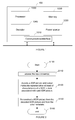
- Figure 2 represents a flowchart of a method for decoding a stream to reconstruct an HDR image according to a specific and non-limiting embodiment.
- a receiver accesses a stream, e.g. an HEVC compliant stream.
- the receiver decodes a SDR picture and colour metadata from the stream.
- the colour metadata are representative at least of characteristics of a high dynamic range picture associated with the standard dynamic range picture.
- the colour metadata are representative of characteristics of a mastering display used in mastering the HDR picture associated with the SDR picture.
- the colour metadata are encapsulated in a Mastering Display Colour Volume SEI message associated with the SDR picture.
- HEVC High Efficiency Video Coding
- white_point_x and white_point_y specify the normalized x and y chromaticity coordinates, respectively, of the white point of the mastering display.
- max_display_mastering_luminance and min_display_mastering_luminance specify the nominal maximum and minimum display luminance, respectively, of the mastering display.
- max_display_mastering_luminance and min_display_mastering_luminance thus specify a luminance range.
- This SEI message identifies the colour volume (the colour primaries, white point and luminance range - i.e. max and min luminance values) of a display considered to be the mastering display for the associated video content - e.g., the colour volume of a display that was used for viewing while authoring the video content.
- the described mastering display is a three-colour additive display system that has been configured to use the indicated mastering colour volume.
- the SDR picture is the associated video content. Indeed, the SDR picture is considered to be in the coded layer-wise video sequence (CLVS).
- CLVS is a sequence of pictures and the associated non-VCL NAL units of the base layer of a coded video sequence (CVS).
- the SEI message is used in a different way to transmit the colour volume (the colour primaries, white point and luminance range) of a display considered to be the mastering display for the HDR picture which is not the one encoded in the stream and thus not in the CLVS.
- This makes it possible to use existing syntax elements to transmit data relevant for HDR reconstruction.
- the colour metadata are representative of a content light level of the high dynamic range picture.
- the colour metadata are encapsulated in a Content Light Level information SEI message associated with the SDR picture.
- a Content Light Level information SEI message associated with the SDR picture.
- Such a message is for example disclosed in sections D2.35 and D3.35 of the document JCTVC-V1005-v1 entitled "High Efficiency Video Coding (HEVC) Screen Content Coding: Draft 5" content_light_level_info( payloadSize ) ⁇ Descriptor max_content_light_level u(16) max_pic_average_light_level u(16) ⁇ max_content_light_level, when not equal to 0, indicates an upper bound on the maximum light level among all individual samples in a 4:4:4 representation of red, green, and blue colour primary intensities (in the linear light domain) for the pictures of the CLVS.
- HEVC High Efficiency Video Coding
- max_pic_average_light_level when not equal to 0, indicates an upper bound on the maximum average light level among the samples in a 4:4:4 representation of red, green, and blue colour primary intensities (in the linear light domain) for any individual picture of the CLVS.
- This SEI message identifies upper bounds for the nominal target brightness light level of the pictures of the CLVS.
- the colour metadata may comprise two parts: a first part being representative of characteristics of a mastering display used in mastering a HDR picture associated with the SDR picture (possibly encapsulated in the MDCV SEI message) and a second part being representative of a content light level of the high dynamic range picture associated with the SDR picture (possibly encapsulated in a CLL SEI message).
- the receiver reconstructs a HDR picture from the decoded SDR picture and from the colour metadata.
- Different embodiments of the HDR picture reconstruction step are disclosed with reference to figures 5 to 8 .
- Reconstructing the HDR picture from the decoded SDR picture and the colour metadata comprises at least:
- Figure 3 represents an exemplary architecture of a transmitter 100 configured to encode a HDR image in a stream according to a non-limiting embodiment.
- the transmitter 200 comprises one or more processor(s) 2000, which could comprise, for example, a CPU, a GPU and/or a DSP (English acronym of Digital Signal Processor), along with internal memory 2030 (e.g. RAM, ROM, and/or EPROM).
- the transmitter 200 comprises one or more communication interface(s) 2010 (e.g. a keyboard, a mouse, a touchpad, a webcam), each adapted to display output information and/or allow a user to enter commands and/or data (e.g. a stream); and a power source 2020 which may be external to the transmitter 200.
- the transmitter 200 may also comprise one or more network interface(s) (not shown).
- Encoder module 2040 represents the module that may be included in a device to perform the coding functions.
- encoder module 2040 may be implemented as a separate element of the transmitter 200 or may be incorporated within processor(s) 2000 as a combination of hardware and software as known to those skilled in the art.
- the HDR image may be obtained from a source. According to different embodiments, the source can be, but is not limited to:
- FIG. 4 represents a flowchart of a method for encoding a HDR image in a stream according to a specific and non-limiting embodiment.
- This method is the inverse of the decoding method. All the embodiments disclosed with respect to the decoding method apply to the encoding method.
- the method starts at step S200.
- a transmitter accesses a HDR image.
- the transmitter accesses a HDR picture.
- the transmitter determine a SDR picture from the HDR picture. This step is disclosed with reference to figure 9 to 12 . Determining the SDR picture from the accessed HDR picture comprises at least:
- the transmitter obtains colour metadata representative at least of characteristics of a high dynamic range picture associated with the standard dynamic range picture.
- the color metadata may be representative of a mastering display used in mastering the HDR picture associated with the SDR picture and/or of a content light level of the high dynamic range picture associated with the SDR picture
- the transmitter encodes the determined SDR picture and the obtained color metadata in a stream, e.g. in an HEVC compliant stream.
- the color metadata may be encapsulated in the SEI messages mentioned with respect to figure 2 for the decoding method.
- the method ends at step S280.
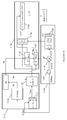
- Figure 5 represents a flowchart of a method for decoding a stream to reconstruct an HDR image according to another specific and non-limiting embodiment.
- a decoder DEC obtains a luminance component L" and two chrominance components C"1, C"2 either from a local or remote memory or by decoding at least partially a stream F.
- the stream F is representative of the SDR picture and of the color metadata (e.g. MDVC and/or CLL SEI message).
- a module IGM obtains a final luminance component L and two final chrominance components C1, C2 from the luminance L" and chrominance C"1, C"2 components by applying an inverse mapping on the colors obtained from the luminance L" and chrominance C"1, C"2 components.
- Figure 6 details step 22.
- a module ILCC obtains (step 222) the final luminance component L by linearly combining together the luminance component L" and the two chrominance components C"1, C"2, and the two final chrominance components C1, C2 are obtained by scaling (step 221) each of the two chrominance components C"1, C"2 by a factor ⁇ ( L ( i )) that depends on the value of each pixel i of the final luminance component L.
- ⁇ L L " + mC 1 " + nC 2 "
- C 1 ⁇ L i * C 1 "
- C 2 ⁇ L i * C 2 " where m and n are coefficient (real values).
- the factor further depends on a modulation value Ba.
- Equation (J) is considered as being an inverse mapping applies on the colors obtained from the luminance L" and chrominance C"1, C"2 components. Equation (J) is directly obtained from equation (A) applied on the encoder side that is considered as being a color mapping.
- This embodiment is advantageous because it ensures that the final luminance component L does not exceed a potential clipping value that is usually used by the decoder to define a luminance peak.
- a luminance peak is required by a decoder and when the final luminance component L is given by equation (J), the final luminance component L is clipped introducing some artefacts.
- the modulation value Ba and/or the coefficients m and n are obtained from a remote or local memory such a Look-Up-Table, or from a stream BF.
- the factor ⁇ -1 ( L ( i )) is obtained from a Look-Up-Table (LUT) for a specific value L(i) of the final luminance component L and, optionally further from a specific modulation value Ba and.
- LUT Look-Up-Table
- a specific factor ⁇ -1 ( L ( i )) is stored in a LUT for each specific modulation value Ba.
- the factor ⁇ -1 ( L ( i )) for a specific modulation value Ba is obtained for a value of a pixel of the final luminance component L by interpolating the luminance peaks between the multiple luminance peaks for which LUT are stored.
- a module INVC obtains at least one color component Ec of the color picture to be decoded from the final luminance L component and the two final chrominance C1, C2 components.
- the HDR picture is formed of the at least one color component Ec.
- Figure 7 details step 23.
- the non-linear function f -1 is the inverse of a non-linear function f applied on the transmitter side.
- the embodiments of the function f -1 are defined according to the embodiments of the function f.
- the parameters of the non-linear function f -1 (such as a, b, c or ⁇ ) and/or the information data Inf is (are) obtained from a local or remote memory (for example the non-linear function is built from a Look-Up Table indexed by a maximum luminance of the mastering display, and/or from the maximum luminance of the HDR picture, and/or from the color primaries and white point of the mastering display used in mastering the HDR picture) and/or from a stream BF.
- a local or remote memory for example the non-linear function is built from a Look-Up Table indexed by a maximum luminance of the mastering display, and/or from the maximum luminance of the HDR picture, and/or from the color primaries and white point of the mastering display used in mastering the HDR picture
- the non-linear function f -1 is the inverse of a gamma function.
- Y 1 L 1 / ⁇ B
- Y 1 equals Y or Y/Ba according to the embodiments of eq. (A3) or (A4)
- B is a constant value
- ⁇ is a parameter (real value strictly below 1).
- the non-linear function f -1 is the inverse of a S-Log function.
- the non-linear function f is the inverse of either a gamma correction or a SLog correction according to the pixel values of the component Y. This is indicated by the information data Inf.
- a module ILC obtains at least one color component Ec from the first component Y, the two final chrominance components C1, C2, and from a factor r(L) that depends on the final luminance component L.
- the decoded color picture is then obtained by combining together the at least one color component Ec.
- the factor r(L) is determined by a module RM in a step 240.
- Figure 8 represents a flowchart of a method for decoding a stream to reconstruct an HDR image according to another specific and non-limiting embodiment.
- This decoding method depends on a set of two-variable functions ⁇ '(Ba,L) and g -1 (Ba,L) and of two constant parameters a and b that are used for the mapping from SDR to HDR of the luminance and the chrominance such that colors, as well as texture, are preserved in the SDR image/video compared to the original HDR image/video.
- g(Ba, L) is preferably a Slog function in the variable L
- the triplet (a, b, ⁇ ') is optimized to lead to the best possible SDR/HDR color matching (hue and perceived saturation) depending on the peak luminance, the input/output gamut's, and the backlight value Ba.
- the encoding involves the function ⁇ "(Ba,L), and the decoding involves the function ⁇ '(Ba,L).
- the function ⁇ " is usually optimized on the encoder side.
- the functions ⁇ ' are usually stored as Look-Up Tables indexed by the peak luminance, the input/output gamut's, and possibly the backlight value Ba.
- step 1230 corrected luminance and chrominance components L', U', V' are obtained from the stream F.
- the values of the luminance component L are always higher than the values of the corrected luminance component L':
- L L ′ + max 0 , aU ′ + bV ′
- This embodiment is advantageous because it ensures that the luminance component L does not exceed a potential clipping value that is usually used by the decoder to define a luminance peak.
- step 1220 at least one color components Ec (in the shown example RGB HDR ) of the HDR picture to be decoded are recovered from the corrected chrominance components U', V' and the first component Y (or sqrt(Y)).
- a multiplication of the corrected chrominance components U', V' by a common multiplicative factor ⁇ ' is performed to obtain the intermediate chrominance components, which are used in a further sub-step 1222 for obtaining a second component S:
- S Y + k 0 U r 2 + k 1 V r 2 + k 2 U r V r .
- the color components of the decoded color picture RGB HDR are determined in a next sub-step 1224 as the squares of R # G # B # .
- the method allows, for example, a SDR to HDR de-mapping that recovers R#G#B# representative of the RGB HDR components, from a SDR luma component L and two SDR chroma components UV, wherein a HDR luminance component Y is deduced from L, a value T is computed as a linear combination of U 2 ,V 2 and U*V, S is computed as the square root of Y-T and R # G # B # is then determined as the product of a 3x3 matrix and SUV, applied to each pixel of an input SDR picture.
- the described decoding scheme allows the distribution of a compressed HDR picture while, at the same time, distributing an associated SDR picture representative of a color-graded version of the HDR picture.
- the determination of ⁇ " is sufficient to define both the encoder end the decoder.
- the problem to solve is to find ⁇ " such that SDR L'U"V" colors correspond at best to the input HDR colors (hue and perceived saturation) and the process is decodable, i.e. the scaling by ⁇ " avoids clipping in U"V" as best as possible.
- ⁇ " is determined on the encoder for different values of the nominal maximum display luminance of the mastering display or of upper bound on the maximum light level among all individual samples of the HDR picture and for different color gamuts of the HDR picture(primaries and white point). Therefore, on the decoder side, LUTs of ⁇ ' values are preferentially stored in the decoder in order to avoid their calculation. The appropriate value of ⁇ ' is thus derived from the decoded color metadata (e.g. MDCV, CLL).
- the decoded color metadata e.g. MDCV, CLL
- Figure 9 represents a flowchart of a method for encoding a HDR picture I in a stream F according to another specific and non-limiting embodiment.
- a module C obtains a luminance component L and two chrominance components C1 and C2 from a HDR picture I to be encoded.
- the components (L, C1, C2) may belong to the YUV color space, obtained after applying an OETF on the HDR picture I, and the color components Ec may belong either to a linear RGB or XYZ color space.
- Step 11 is detailed on Figure 10 .
- the dynamic range of the component Y is reduced in order that the luminance values of the component L are represented by using 10 bits.
- a, b and c are parameters (real values) of a SLog curve determined such that f(0) and f(1) are invariant, and the derivative of the SLog curve is continuous in 1 when prolonged by a gamma curve below 1.
- a, b and c are functions of the parameter ⁇ .
- Table 1 Typical values are shown in Table 1. Table 1 ⁇ a B C 1/2.0 0.6275 0.2550 0.8575 1/2.4 0.4742 0.1382 0.9386 1/2.8 0.3861 0.0811 0.9699
- a value of ⁇ close to 1/2.5 is efficient in terms of HDR compression performance as well as good viewability of the obtained SDR luma.
- the non-linear function f is either a gamma correction or a SLog correction according to the pixel values of the component Y.
- the module FM applies either the gamma correction or the SLog correction according to the pixel values of the component Y.
- An information data Inf may indicate whether either the gamma correction or Slog correction applies.
- the gamma correction is applied and otherwise the SLog correction is applied.
- the modulation value Ba is an average, median, min or max value of the pixel values of the component Y.
- These operations may be performed in the linear HDR luminance domain Y lin or in a non-linear domain like ln(Y) or Y ⁇ with ⁇ 1.
- a modulation value Ba is determined for each color picture, a Group of Pictures (GOP) or for a part of a color picture such as, but not limited to, a slice or a Transfer Unit as defined in HEVC.
- GOP Group of Pictures
- the value Ba and/or the parameters of the non-linear function f (such as a, b, c or y) and/or the information data Inf is (are) stored in a local or remote memory and/or added into a stream BF as illustrated in Figures 9 and 10 .
- a color component Ec may be obtained directly from a local or a remote memory or by applying a color transform on the HDR picture I.
- Scaling by a factor means multiplying by the factor or dividing by the inverse of the factor.
- the value Y(i) of a pixel of the component Y depends non-ambiguously on the value L(i) of a pixel of the luminance component L, such that the ratio can be written as a function of L(i) only.
- This embodiment is advantageous because scaling each color component Ec by the factor r(L) that further depends on the component Y preserves the hue of the colors of the HDR picture I and thus improves the visual quality of the decoded color picture.
- colorfulness, chroma, and saturation refer to the perceived intensity of a specific color.
- Colorfulness is the degree of difference between a color and gray.
- Chroma is the colorfulness relative to the brightness of another color that appears white under similar viewing conditions.
- Saturation is the colorfulness of a color relative to its own brightness.
- a highly colorful stimulus is vivid and intense, while a less colorful stimulus appears more muted, closer to gray.
- a color is a "neutral" gray (a picture with no colorfulness in any of its colors is called grayscale). Any color can be described from its colorfulness (or chroma or saturation), lightness (or brightness), and hue.
- the definition of the hue and saturation of the color depends on the color space used to represent the color.
- the saturation s uv is defined as the ratio between the chroma C uv * over the luminance L *.
- the colors of the picture I2 are thus differently perceived by a human being because the saturation and the hue of the colors changed.
- the method (step 150) determines the chrominance components C1 and C2 of the picture I2 in order that the hue of the colors of the picture I2 best match the hue of the colors of the HDR picture I.
- This last embodiment is advantageous because it prevents the factor from going to zero for very dark pixels, i.e. allows the ratio to be invertible regardless of the pixel value.
- the two chrominance components C1, C2 are obtained from the at least one intermediate color components E'c.
- a module GM maps the luminance L and chrominance C1, C2 components onto a final luminance component L" and two final chrominance components C"1, C"2 so that the gamut G2 of colors obtained from the final luminance (L") and chrominance (C"1, C"2) components maps onto the gamut G1 of the colors of the HDR picture I to be encoded.
- the step 12 is detailed on Figure 11 .
- the factor ⁇ -1 ( L ( i )) further depends on a modulation value Ba.
- the coefficients m and n are stored in either a local or remote memory and/or added to a stream BF as illustrated in figure 11 .
- the factor ⁇ -1 ( L ( i )) is obtained from a Look-Up-Table (LUT) for a specific luminance value L(i), and optionally further for a specific modulation value Ba and.
- LUT Look-Up-Table
- a specific factor ⁇ -1 ( L ( i )) is stored in a LUT for each specific modulation value Ba.
- the factor ⁇ -1 ( L ( i )) is obtained for a value of a pixel of the luminance component L by interpolating the luminance peaks between the multiple luminance peaks for which LUT are stored.
- the factor ⁇ -1 ( L ( i )) for a specific modulation value Ba is obtained for a value of a pixel of the luminance component L by interpolating the luminance peaks between the multiple luminance peaks for which LUT are stored.
- the factor ⁇ -1 ( L ( i )) and the coefficients m and n in equation (A) are obtained as follows.
- L " C 1 " C 2 " ⁇ Ba Y L C 1 C 2
- ⁇ Ba ( Y ) is a mapping function depending on the linear luminance Y of the HDR picture I.
- the linear luminance Y is obtained as a linear combination of the components Ec of the HDR picture I.
- S Y 0 ⁇ R Y 0 ⁇ G Y 0 ⁇ B Y 0
- the purpose of the mapping function ⁇ Ba ( L ) is to map back S Y 0 onto the three primaries of the gamut G2.
- the mapping matrix is determined up to a scaling factor ⁇ .
- Equations (B) and (G) show that the mapping function has two effects: first, the dynamic of the luminance component L is scaled by a scaling factor ⁇ and, second, the chrominance components C1 and C2 are also scaled by a scaling factor ⁇ -1 .
- the luminance component L is obtained back from L", C"1, C"2 by applying the matrix ⁇ 0 ⁇ 1 and then, since L is known, one finds the factor ⁇ ( Ba , L ( i )) to apply to the final chrominance components C"1, C"2 to get the chrominance components C1, C2 back.
- mapping function ⁇ Ba ( L ) is then provided by equation (H) where the constant matrix ⁇ 0 is used for all luminance level up to the luminance peak P of the color image I, and ⁇ defined on the full range of luminance up to the luminance peak P.
- the factor ⁇ -1 ( Ba , L ( i ), m,n ) is considered as depending also on the coefficients m and n which are given as explained in the previous embodiment.
- the factor ⁇ -1 is thus the single unknown value in step 12.
- the factor ⁇ -1 is obtained such that a gamut distortion calculated between the gamuts G1 and G2 is minimized.
- the factor ⁇ -1 is the optimal factor under the condition of gamut preservation.
- an encoder ENC encodes the final luminance L" component and the two final chrominance components C"1, C"2 in a stream F, e.g.an HEVC compliant stream.
- the encoded component L" and chrominance components C"1, C"2 are stored in a local or remote memory and/or added into a stream F.
- Figure 12 represents a flowchart of a method for encoding an HDR picture in a stream according to another specific and non-limiting embodiment.
- This encoding method depends on a set of two-variable functions ⁇ "(Ba,L) and g(Ba,L) and of two constant parameters a and b that are used for the mapping from SDR to HDR of the luminance and the chrominance such that colors, as well as texture, are preserved in the SDR image/video compared to the original HDR image/video.
- g(Ba,L) is preferably a Slog function in the variable L
- the triplet (a, b, ⁇ ") is optimized to lead to the best possible SDR/HDR color matching (hue and perceived saturation) depending on the peak luminance, the input/output gamut's, and the backlight value Ba.
- the encoding involves the function ⁇ "(Ba,L), and the decoding involves the function ⁇ '(Ba,L).
- the function ⁇ " is usually optimized on the encoder side. On the decoder side the functions ⁇ ' are usually stored as Look-Up Tables that indexed by the peak luminance, the input/output gamut's, and possibly the backlight value Ba.
- the encoding method comprises a luminance dynamic reduction step 1110.
- a modulation value also called backlight value
- Different methods can be used to calculate the modulation value, for example, but not limited to, using an average, median, minimum or maximum value of the HDR luminance. These operations may be performed in the linear HDR luminance domain Y HDR,lin or in a non-linear domain like ln (Y HDR,lin ) or Y HDR , lin ⁇ with ⁇ 1.
- a color picture is considered as having three color components in which the pixel values of the color picture are represented.
- the present disclosure is not limited to any color space in which the three components are represented but extends to any color space such as RGB, CIELUV, XYZ, CIELab, etc.
- Ec refers to RGB HDR in the Figures.
- the dynamic of the original luminance Y dynamic is reduced to obtain a luminance component L from the original luminance Y and the modulation value Ba by applying a non-linear function that depends on from the original luminance Y and the modulation value Ba.
- the luminance component L is a luminance component of the SDR picture, therefore it can also be referred to as a Y component, more precisely as a Y SDR component of a YUV BT709 or YUV BT2020 standard color space.
- step 1120 two chrominance components C1 and C2 are determined from the color components RGB HDR of the color picture.
- intermediate components R # B # G # are obtained by taking the square root of the color components RGB HDR .
- reduced components R ⁇ G ⁇ B ⁇ are obtained by a multiplication of the intermediate components R # B # G # by a common multiplicative factor ⁇ ". The factor ⁇ "(Ba,L) depends on the luminance component L and the modulation value Ba.
- step 1130 a correction of the luminance component L and the chrominance components C1, C2 is performed to obtain the corrected luminance component L' and the corrected chrominance components U' and V'.
- This correction obtained by a gamut mapping such that the perceived colors of the gamut G1 of the corrected components L', U', V' correspond to the perceived color of the gamut G2 of the components of the HDR picture.
- colorfulness, chroma, and saturation refer to the perceived intensity of a specific color.
- Colorfulness is the degree of difference between a color and gray.
- Chroma is the colorfulness relative to the brightness of another color that appears white under similar viewing conditions.
- Saturation is the colorfulness of a color relative to its own brightness.
- a highly colorful stimulus is vivid and intense, while a less colorful stimulus appears more muted, closer to gray.
- a color is a "neutral" gray (a picture with no colorfulness in any of its colors is called grayscale). Any color can be described from its colorfulness (or chroma or saturation), lightness (or brightness), and hue.
- the definition of the hue and saturation of the color depends on the color space used to represent the color.
- the saturation s uv is defined as the ratio between the chroma C uv * over the luminance L *.
- the colors of the picture I2 are thus differently perceived by a human being because the saturation and the hue of the colors changed.
- the method determines the chrominance components C'1 and C'2 of a corrected picture I3 in order that the hue of the colors of the corrected picture I3 best match the hue of the colors of the HDR color picture.
- a sub-step 1131 1132, the common multiplicative factor ⁇ "used in the second step 1120 is determined.
- L' is generated from L.
- the corrected components L', C'1, C'2 are obtained from the luminance component L and the chrominance components C1, C2 by the following equations
- the values of the corrected luminance component L' are always lower than the values of the luminance component L:
- L ′ L ⁇ max 0 , mC 1 ′ + nC 2 ′
- the modulation value Ba is encoded in the bitstream F as well as the SDR picture L'C'1 C'2, i.e. L'U'V' on the figure 1 .
- the implementations described herein may be implemented in, for example, a method or a process, an apparatus, a software program, a data stream, or a signal. Even if only discussed in the context of a single form of implementation (for example, discussed only as a method or a device), the implementation of features discussed may also be implemented in other forms (for example a program).
- An apparatus may be implemented in, for example, appropriate hardware, software, and firmware.
- the methods may be implemented in, for example, an apparatus such as, for example, a processor, which refers to processing devices in general, including, for example, a computer, a microprocessor, an integrated circuit, or a programmable logic device. Processors also include communication devices, such as, for example, computers, cell phones, portable/personal digital assistants ("PDAs”), and other devices that facilitate communication of information between end-users.
- PDAs portable/personal digital assistants
- Implementations of the various processes and features described herein may be embodied in a variety of different equipment or applications, particularly, for example, equipment or applications.
- equipment examples include an encoder, a decoder, a post-processor processing output from a decoder, a pre-processor providing input to an encoder, a video coder, a video decoder, a video codec, a web server, a set-top box, a laptop, a personal computer, a cell phone, a PDA, and other communication devices.
- the equipment may be mobile and even installed in a mobile vehicle.
- the methods may be implemented by instructions being performed by a processor, and such instructions (and/or data values produced by an implementation) may be stored on a processor-readable medium such as, for example, an integrated circuit, a software carrier or other storage device such as, for example, a hard disk, a compact diskette (“CD"), an optical disc (such as, for example, a DVD, often referred to as a digital versatile disc or a digital video disc), a random access memory (“RAM”), or a read-only memory (“ROM”).
- the instructions may form an application program tangibly embodied on a processor-readable medium. Instructions may be, for example, in hardware, firmware, software, or a combination.
- a processor may be characterized, therefore, as, for example, both a device configured to carry out a process and a device that includes a processor-readable medium (such as a storage device) having instructions for carrying out a process. Further, a processor-readable medium may store, in addition to or in lieu of instructions, data values produced by an implementation.
- implementations may produce a variety of signals formatted to carry information that may be, for example, stored or transmitted.
- the information may include, for example, instructions for performing a method, or data produced by one of the described implementations.
- a signal may be formatted to carry as data the rules for writing or reading the syntax of a described embodiment, or to carry as data the actual syntax-values written by a described embodiment.
- Such a signal may be formatted, for example, as an electromagnetic wave (for example, using a radio frequency portion of spectrum) or as a baseband signal.
- the formatting may include, for example, encoding a data stream and modulating a carrier with the encoded data stream.
- the information that the signal carries may be, for example, analog or digital information.
- the signal may be transmitted over a variety of different wired or wireless links, as is known.
- the signal may be stored on a processor-readable medium.
Priority Applications (11)
| Application Number | Priority Date | Filing Date | Title |
|---|---|---|---|
| EP16305303.6A EP3220645A1 (de) | 2016-03-18 | 2016-03-18 | Verfahren und vorrichtung zur codierung eines bildes mit hohem dynamikbereich, zugehöriges decodierungsverfahren und decodierungsvorrichtung |
| BR112018068873A BR112018068873A2 (pt) | 2016-03-18 | 2017-03-13 | método e dispositivo para codificar uma imagem de alta faixa dinâmica, método de decodificação correspondente e dispositivo de decodificação |
| PCT/EP2017/055829 WO2017157845A1 (en) | 2016-03-18 | 2017-03-13 | A method and a device for encoding a high dynamic range picture, corresponding decoding method and decoding device |
| JP2018548816A JP6946325B2 (ja) | 2016-03-18 | 2017-03-13 | 高ダイナミックレンジピクチャを符号化する方法及び装置、対応する符号化方法及並びに符号化装置 |
| EP17709456.2A EP3430807B1 (de) | 2016-03-18 | 2017-03-13 | Verfahren und vorrichtung zur kodierung eines bildes mit hohem dynamikbereich, zugehöriges dekodierungsverfahren und dekodierungsvorrichtung |
| CA3017994A CA3017994A1 (en) | 2016-03-18 | 2017-03-13 | A method and a device for encoding a high dynamic range picture, corresponding decoding method and decoding device |
| CN201780028033.9A CN109076231B (zh) | 2016-03-18 | 2017-03-13 | 对hdr图片编码的方法和设备、对应的解码方法和解码设备 |
| RU2018136432A RU2737507C2 (ru) | 2016-03-18 | 2017-03-13 | Способ и устройство для кодирования изображения высокого динамического диапазона, соответствующий способ декодирования и устройство декодирования |
| US16/086,240 US11032579B2 (en) | 2016-03-18 | 2017-03-13 | Method and a device for encoding a high dynamic range picture, corresponding decoding method and decoding device |
| MX2018011255A MX2018011255A (es) | 2016-03-18 | 2017-03-13 | Metodo y dispositivo para codificar una imagen de alto rango dinamico, metodo de decodificacion correspondiente y dispositivo de decodificacion. |
| KR1020187027088A KR102358368B1 (ko) | 2016-03-18 | 2017-03-13 | 하이 다이나믹 레인지 픽처를 인코딩하기 위한 방법 및 디바이스, 대응하는 디코딩 방법 및 디코딩 디바이스 |
Applications Claiming Priority (1)
| Application Number | Priority Date | Filing Date | Title |
|---|---|---|---|
| EP16305303.6A EP3220645A1 (de) | 2016-03-18 | 2016-03-18 | Verfahren und vorrichtung zur codierung eines bildes mit hohem dynamikbereich, zugehöriges decodierungsverfahren und decodierungsvorrichtung |
Publications (1)
| Publication Number | Publication Date |
|---|---|
| EP3220645A1 true EP3220645A1 (de) | 2017-09-20 |
Family
ID=55589786
Family Applications (2)
| Application Number | Title | Priority Date | Filing Date |
|---|---|---|---|
| EP16305303.6A Withdrawn EP3220645A1 (de) | 2016-03-18 | 2016-03-18 | Verfahren und vorrichtung zur codierung eines bildes mit hohem dynamikbereich, zugehöriges decodierungsverfahren und decodierungsvorrichtung |
| EP17709456.2A Active EP3430807B1 (de) | 2016-03-18 | 2017-03-13 | Verfahren und vorrichtung zur kodierung eines bildes mit hohem dynamikbereich, zugehöriges dekodierungsverfahren und dekodierungsvorrichtung |
Family Applications After (1)
| Application Number | Title | Priority Date | Filing Date |
|---|---|---|---|
| EP17709456.2A Active EP3430807B1 (de) | 2016-03-18 | 2017-03-13 | Verfahren und vorrichtung zur kodierung eines bildes mit hohem dynamikbereich, zugehöriges dekodierungsverfahren und dekodierungsvorrichtung |
Country Status (10)
| Country | Link |
|---|---|
| US (1) | US11032579B2 (de) |
| EP (2) | EP3220645A1 (de) |
| JP (1) | JP6946325B2 (de) |
| KR (1) | KR102358368B1 (de) |
| CN (1) | CN109076231B (de) |
| BR (1) | BR112018068873A2 (de) |
| CA (1) | CA3017994A1 (de) |
| MX (1) | MX2018011255A (de) |
| RU (1) | RU2737507C2 (de) |
| WO (1) | WO2017157845A1 (de) |
Cited By (2)
| Publication number | Priority date | Publication date | Assignee | Title |
|---|---|---|---|---|
| CN112400324A (zh) * | 2018-07-20 | 2021-02-23 | 交互数字Vc控股公司 | 用于处理视频信号的方法和装置 |
| WO2024023008A1 (en) * | 2022-07-27 | 2024-02-01 | Interdigital Ce Patent Holdings, Sas | Method for preventing clipping in sl-hdrx systems |
Families Citing this family (10)
| Publication number | Priority date | Publication date | Assignee | Title |
|---|---|---|---|---|
| US10257394B2 (en) | 2016-02-12 | 2019-04-09 | Contrast, Inc. | Combined HDR/LDR video streaming |
| US10264196B2 (en) | 2016-02-12 | 2019-04-16 | Contrast, Inc. | Systems and methods for HDR video capture with a mobile device |
| JP7081835B2 (ja) | 2016-08-09 | 2022-06-07 | コントラスト, インコーポレイテッド | 車両制御のためのリアルタイムhdrビデオ |
| EP3367658A1 (de) * | 2017-02-24 | 2018-08-29 | Thomson Licensing | Verfahren und vorrichtung zur rekonstruktion eines hdr-bildes |
| US11265530B2 (en) | 2017-07-10 | 2022-03-01 | Contrast, Inc. | Stereoscopic camera |
| JP7074461B2 (ja) * | 2017-11-22 | 2022-05-24 | インターデジタル ヴイシー ホールディングス, インコーポレイテッド | ディスプレイ適合hdr画像を再構成する方法およびデバイス |
| US10951888B2 (en) | 2018-06-04 | 2021-03-16 | Contrast, Inc. | Compressed high dynamic range video |
| KR20200095651A (ko) * | 2019-02-01 | 2020-08-11 | 삼성전자주식회사 | 고 동적 범위 콘텐트를 재생하는 전자 장치 및 그 방법 |
| US11330196B2 (en) * | 2020-10-12 | 2022-05-10 | Microsoft Technology Licensing, Llc | Estimating illumination in an environment based on an image of a reference object |
| CN115797152A (zh) * | 2021-09-10 | 2023-03-14 | 北京字跳网络技术有限公司 | 一种颜色映射色卡生成方法及装置 |
Citations (1)
| Publication number | Priority date | Publication date | Assignee | Title |
|---|---|---|---|---|
| WO2013046095A1 (en) * | 2011-09-27 | 2013-04-04 | Koninklijke Philips Electronics N.V. | Apparatus and method for dynamic range transforming of images |
Family Cites Families (21)
| Publication number | Priority date | Publication date | Assignee | Title |
|---|---|---|---|---|
| EP2360926A1 (de) | 2010-01-19 | 2011-08-24 | Fraunhofer-Gesellschaft zur Förderung der Angewandten Forschung e.V. | Bildkodierer und Bilddekodierer |
| US8606009B2 (en) * | 2010-02-04 | 2013-12-10 | Microsoft Corporation | High dynamic range image generation and rendering |
| TWI479898B (zh) | 2010-08-25 | 2015-04-01 | Dolby Lab Licensing Corp | 擴展影像動態範圍 |
| US10298923B2 (en) | 2011-05-16 | 2019-05-21 | Dolby Laboratories Licensing Corporation | Efficient architecture for layered VDR coding |
| US8891863B2 (en) | 2011-06-13 | 2014-11-18 | Dolby Laboratories Licensing Corporation | High dynamic range, backwards-compatible, digital cinema |
| CN103907343B (zh) * | 2011-10-20 | 2017-05-03 | 杜比实验室特许公司 | 用于视频均衡的方法和系统 |
| BR112015026979B1 (pt) * | 2013-04-30 | 2023-04-11 | Sony Corporation | Dispositivos e métodos de transmissão e recepção |
| JP6202330B2 (ja) * | 2013-10-15 | 2017-09-27 | ソニー株式会社 | 復号装置および復号方法、並びに符号化装置および符号化方法 |
| KR101797505B1 (ko) * | 2013-11-13 | 2017-12-12 | 엘지전자 주식회사 | Hdr 방송 서비스 제공을 위한 방송 신호 송수신 방법 및 장치 |
| EP3155799A1 (de) * | 2014-06-12 | 2017-04-19 | Thomson Licensing | Verfahren zur abbildung der quellenfarben eines quelleninhalts |
| EP2958328A1 (de) | 2014-06-20 | 2015-12-23 | Thomson Licensing | Verfahren und Vorrichtung zur Signalisierung in einem Bitstrom eines Bild-/Videoformats eines LDR-Bildes und eines Bild-/Videoformats eines codierten HDR-Bildes von besagtem LDR-Bild und Beleuchtungsbild |
| JP2016058848A (ja) * | 2014-09-08 | 2016-04-21 | ソニー株式会社 | 画像処理装置及び画像処理方法 |
| US9652870B2 (en) * | 2015-01-09 | 2017-05-16 | Vixs Systems, Inc. | Tone mapper with filtering for dynamic range conversion and methods for use therewith |
| CN107211077A (zh) * | 2015-01-29 | 2017-09-26 | 皇家飞利浦有限公司 | 局部动态范围调整颜色处理 |
| US10594978B2 (en) * | 2015-02-11 | 2020-03-17 | Lg Electronics Inc. | Method and device for transmitting and receiving broadcast signal |
| WO2016171508A1 (ko) * | 2015-04-23 | 2016-10-27 | 엘지전자 주식회사 | 방송 신호 송수신 방법 및 장치 |
| KR102129541B1 (ko) * | 2015-08-28 | 2020-07-03 | 애리스 엔터프라이지즈 엘엘씨 | 높은 동적 범위 및 넓은 컬러 영역 시퀀스들의 코딩에서의 컬러 볼륨 변환들 |
| US10043251B2 (en) * | 2015-10-09 | 2018-08-07 | Stmicroelectronics Asia Pacific Pte Ltd | Enhanced tone mapper for high dynamic range images and video |
| US9984446B2 (en) * | 2015-12-26 | 2018-05-29 | Intel Corporation | Video tone mapping for converting high dynamic range (HDR) content to standard dynamic range (SDR) content |
| BR112018068603A2 (pt) | 2016-03-18 | 2019-02-05 | Koninklijke Philips Nv | decodificador e codificador de vídeo e método de decodificação e de codificação vídeo |
| ES2951773T3 (es) * | 2016-03-18 | 2023-10-24 | Koninklijke Philips Nv | Codificación y decodificación de vídeos HDR |
-
2016
- 2016-03-18 EP EP16305303.6A patent/EP3220645A1/de not_active Withdrawn
-
2017
- 2017-03-13 KR KR1020187027088A patent/KR102358368B1/ko active IP Right Grant
- 2017-03-13 BR BR112018068873A patent/BR112018068873A2/pt unknown
- 2017-03-13 CN CN201780028033.9A patent/CN109076231B/zh active Active
- 2017-03-13 RU RU2018136432A patent/RU2737507C2/ru active
- 2017-03-13 WO PCT/EP2017/055829 patent/WO2017157845A1/en active Application Filing
- 2017-03-13 MX MX2018011255A patent/MX2018011255A/es unknown
- 2017-03-13 EP EP17709456.2A patent/EP3430807B1/de active Active
- 2017-03-13 JP JP2018548816A patent/JP6946325B2/ja active Active
- 2017-03-13 US US16/086,240 patent/US11032579B2/en active Active
- 2017-03-13 CA CA3017994A patent/CA3017994A1/en active Pending
Patent Citations (1)
| Publication number | Priority date | Publication date | Assignee | Title |
|---|---|---|---|---|
| WO2013046095A1 (en) * | 2011-09-27 | 2013-04-04 | Koninklijke Philips Electronics N.V. | Apparatus and method for dynamic range transforming of images |
Non-Patent Citations (5)
| Title |
|---|
| "High Efficiency Video Coding SERIES H: AUDIOVISUAL AND MUL TIMEDIA SYSTEMS", RECOMMENDATION ITU-T H.265, TELECOMMUNICATION STANDARDIZATION SECTOR OF ITU, April 2013 (2013-04-01) |
| JOSHI R ET AL: "HEVC Screen Content Coding Draft Text 4", 21. JCT-VC MEETING; 19-6-2015 - 26-6-2015; WARSAW; (JOINT COLLABORATIVE TEAM ON VIDEO CODING OF ISO/IEC JTC1/SC29/WG11 AND ITU-T SG.16 ); URL: HTTP://WFTP3.ITU.INT/AV-ARCH/JCTVC-SITE/,, no. JCTVC-U1005-v2, 5 September 2015 (2015-09-05), XP030117647 * |
| REC. ITU-R BT.2020-1, June 2014 (2014-06-01) |
| REC. ITU-R BT.709-5, April 2002 (2002-04-01) |
| SEGALL A ET AL: "Tone mapping SEI", 19. JVT MEETING; 31-03-2006 - 07-04-2006; GENEVA, CH; (JOINT VIDEOTEAM OF ISO/IEC JTC1/SC29/WG11 AND ITU-T SG.16 ),, no. JVT-S087, 1 April 2006 (2006-04-01), XP030006466, ISSN: 0000-0409 * |
Cited By (2)
| Publication number | Priority date | Publication date | Assignee | Title |
|---|---|---|---|---|
| CN112400324A (zh) * | 2018-07-20 | 2021-02-23 | 交互数字Vc控股公司 | 用于处理视频信号的方法和装置 |
| WO2024023008A1 (en) * | 2022-07-27 | 2024-02-01 | Interdigital Ce Patent Holdings, Sas | Method for preventing clipping in sl-hdrx systems |
Also Published As
| Publication number | Publication date |
|---|---|
| JP6946325B2 (ja) | 2021-10-06 |
| KR20180123046A (ko) | 2018-11-14 |
| RU2018136432A (ru) | 2020-04-20 |
| US11032579B2 (en) | 2021-06-08 |
| US20200296428A1 (en) | 2020-09-17 |
| EP3430807A1 (de) | 2019-01-23 |
| CA3017994A1 (en) | 2017-09-21 |
| RU2018136432A3 (de) | 2020-05-25 |
| EP3430807B1 (de) | 2021-09-29 |
| JP2019513323A (ja) | 2019-05-23 |
| CN109076231A (zh) | 2018-12-21 |
| KR102358368B1 (ko) | 2022-02-03 |
| RU2737507C2 (ru) | 2020-12-01 |
| BR112018068873A2 (pt) | 2019-01-22 |
| CN109076231B (zh) | 2021-06-08 |
| MX2018011255A (es) | 2019-08-16 |
| WO2017157845A1 (en) | 2017-09-21 |
Similar Documents
| Publication | Publication Date | Title |
|---|---|---|
| EP3430807B1 (de) | Verfahren und vorrichtung zur kodierung eines bildes mit hohem dynamikbereich, zugehöriges dekodierungsverfahren und dekodierungsvorrichtung | |
| US11178412B2 (en) | Method and apparatus of encoding and decoding a color picture | |
| RU2710291C2 (ru) | Способы и устройства для кодирования и декодирования цветного изображения hdr | |
| US11006151B2 (en) | Method and device for encoding both a HDR picture and a SDR picture obtained from said HDR picture using color mapping functions | |
| US10666990B2 (en) | Method and device for matching colors between color pictures of different dynamic range | |
| EP3341918B1 (de) | Codierungs- und decodierungsverfahren und zugehörige vorrichtungen | |
| EP3051489A1 (de) | Verfahren und Vorrichtung zur Codierung und Decodierung eines Farbbildes |
Legal Events
| Date | Code | Title | Description |
|---|---|---|---|
| PUAI | Public reference made under article 153(3) epc to a published international application that has entered the european phase |
Free format text: ORIGINAL CODE: 0009012 |
|
| AK | Designated contracting states |
Kind code of ref document: A1 Designated state(s): AL AT BE BG CH CY CZ DE DK EE ES FI FR GB GR HR HU IE IS IT LI LT LU LV MC MK MT NL NO PL PT RO RS SE SI SK SM TR |
|
| AX | Request for extension of the european patent |
Extension state: BA ME |
|
| STAA | Information on the status of an ep patent application or granted ep patent |
Free format text: STATUS: THE APPLICATION IS DEEMED TO BE WITHDRAWN |
|
| 18D | Application deemed to be withdrawn |
Effective date: 20180321 |