EP3220080B1 - Dispositif d'échange de chaleur d'extrémité froide et réfrigérateur à semi-conducteurs - Google Patents
Dispositif d'échange de chaleur d'extrémité froide et réfrigérateur à semi-conducteurs Download PDFInfo
- Publication number
- EP3220080B1 EP3220080B1 EP15869098.2A EP15869098A EP3220080B1 EP 3220080 B1 EP3220080 B1 EP 3220080B1 EP 15869098 A EP15869098 A EP 15869098A EP 3220080 B1 EP3220080 B1 EP 3220080B1
- Authority
- EP
- European Patent Office
- Prior art keywords
- plane
- heat exchanging
- cold end
- refrigerant
- end heat
- Prior art date
- Legal status (The legal status is an assumption and is not a legal conclusion. Google has not performed a legal analysis and makes no representation as to the accuracy of the status listed.)
- Active
Links
Images


Classifications
-
- F—MECHANICAL ENGINEERING; LIGHTING; HEATING; WEAPONS; BLASTING
- F25—REFRIGERATION OR COOLING; COMBINED HEATING AND REFRIGERATION SYSTEMS; HEAT PUMP SYSTEMS; MANUFACTURE OR STORAGE OF ICE; LIQUEFACTION SOLIDIFICATION OF GASES
- F25B—REFRIGERATION MACHINES, PLANTS OR SYSTEMS; COMBINED HEATING AND REFRIGERATION SYSTEMS; HEAT PUMP SYSTEMS
- F25B21/00—Machines, plants or systems, using electric or magnetic effects
- F25B21/02—Machines, plants or systems, using electric or magnetic effects using Peltier effect; using Nernst-Ettinghausen effect
-
- F—MECHANICAL ENGINEERING; LIGHTING; HEATING; WEAPONS; BLASTING
- F25—REFRIGERATION OR COOLING; COMBINED HEATING AND REFRIGERATION SYSTEMS; HEAT PUMP SYSTEMS; MANUFACTURE OR STORAGE OF ICE; LIQUEFACTION SOLIDIFICATION OF GASES
- F25D—REFRIGERATORS; COLD ROOMS; ICE-BOXES; COOLING OR FREEZING APPARATUS NOT OTHERWISE PROVIDED FOR
- F25D19/00—Arrangement or mounting of refrigeration units with respect to devices or objects to be refrigerated, e.g. infrared detectors
-
- F—MECHANICAL ENGINEERING; LIGHTING; HEATING; WEAPONS; BLASTING
- F25—REFRIGERATION OR COOLING; COMBINED HEATING AND REFRIGERATION SYSTEMS; HEAT PUMP SYSTEMS; MANUFACTURE OR STORAGE OF ICE; LIQUEFACTION SOLIDIFICATION OF GASES
- F25D—REFRIGERATORS; COLD ROOMS; ICE-BOXES; COOLING OR FREEZING APPARATUS NOT OTHERWISE PROVIDED FOR
- F25D11/00—Self-contained movable devices, e.g. domestic refrigerators
-
- F—MECHANICAL ENGINEERING; LIGHTING; HEATING; WEAPONS; BLASTING
- F25—REFRIGERATION OR COOLING; COMBINED HEATING AND REFRIGERATION SYSTEMS; HEAT PUMP SYSTEMS; MANUFACTURE OR STORAGE OF ICE; LIQUEFACTION SOLIDIFICATION OF GASES
- F25D—REFRIGERATORS; COLD ROOMS; ICE-BOXES; COOLING OR FREEZING APPARATUS NOT OTHERWISE PROVIDED FOR
- F25D16/00—Devices using a combination of a cooling mode associated with refrigerating machinery with a cooling mode not associated with refrigerating machinery
-
- F—MECHANICAL ENGINEERING; LIGHTING; HEATING; WEAPONS; BLASTING
- F25—REFRIGERATION OR COOLING; COMBINED HEATING AND REFRIGERATION SYSTEMS; HEAT PUMP SYSTEMS; MANUFACTURE OR STORAGE OF ICE; LIQUEFACTION SOLIDIFICATION OF GASES
- F25D—REFRIGERATORS; COLD ROOMS; ICE-BOXES; COOLING OR FREEZING APPARATUS NOT OTHERWISE PROVIDED FOR
- F25D17/00—Arrangements for circulating cooling fluids; Arrangements for circulating gas, e.g. air, within refrigerated spaces
- F25D17/02—Arrangements for circulating cooling fluids; Arrangements for circulating gas, e.g. air, within refrigerated spaces for circulating liquids, e.g. brine
-
- F—MECHANICAL ENGINEERING; LIGHTING; HEATING; WEAPONS; BLASTING
- F25—REFRIGERATION OR COOLING; COMBINED HEATING AND REFRIGERATION SYSTEMS; HEAT PUMP SYSTEMS; MANUFACTURE OR STORAGE OF ICE; LIQUEFACTION SOLIDIFICATION OF GASES
- F25B—REFRIGERATION MACHINES, PLANTS OR SYSTEMS; COMBINED HEATING AND REFRIGERATION SYSTEMS; HEAT PUMP SYSTEMS
- F25B2321/00—Details of machines, plants or systems, using electric or magnetic effects
- F25B2321/02—Details of machines, plants or systems, using electric or magnetic effects using Peltier effects; using Nernst-Ettinghausen effects
- F25B2321/025—Removal of heat
- F25B2321/0252—Removal of heat by liquids or two-phase fluids
-
- F—MECHANICAL ENGINEERING; LIGHTING; HEATING; WEAPONS; BLASTING
- F25—REFRIGERATION OR COOLING; COMBINED HEATING AND REFRIGERATION SYSTEMS; HEAT PUMP SYSTEMS; MANUFACTURE OR STORAGE OF ICE; LIQUEFACTION SOLIDIFICATION OF GASES
- F25B—REFRIGERATION MACHINES, PLANTS OR SYSTEMS; COMBINED HEATING AND REFRIGERATION SYSTEMS; HEAT PUMP SYSTEMS
- F25B2339/00—Details of evaporators; Details of condensers
- F25B2339/02—Details of evaporators
Definitions
- the present invention relates to a refrigeration apparatus and, more particularly, to a cold end heat exchanging device and a semiconductor refrigerator having the cold end heat exchanging device.
- a semiconductor refrigerator is also known as a thermoelectric refrigerator.
- a semiconductor refrigerator uses a semiconductor cooler to achieve refrigeration by means of heat dissipation and conduction technologies through efficient annular double-layer heat pipes and automatic variable pressure and flow control technology, without the need of any refrigeration medium and mechanical moving components, and solves the problems in applications of traditional mechanical refrigerators, such as pollution from media and mechanical vibration.
- the semiconductor refrigerator has to effectively transfer the temperature at the cold end of the semiconductor cooler into the storage compartment of the refrigerator.
- the prior art generally uses a heat radiator for forced convection, which is in direct contact with the cold end of the semiconductor cooler and exchanges heat with the storage compartment.
- the heat conduction and exchange efficiency between solid bodies is low, and is not conducive to the optimal performance of the semiconductor.
- the heat dissipation fins are bulky and take up much space in the refrigerator, and when combined with a fan, the noise is increased and the continuous operation of the fan reduces its reliability.
- CN 103 199 316 A discloses a battery pack and a heat dissipation structure.
- CN 203 810 826 U relates to refrigeration equipment, and particularly to a semiconductor cooling refrigerator.
- US 2013/291563 A1 concerns two-phase heat exchanger mounting.
- An object of a first aspect of the present invention is to provide a cold end heat exchanging device having high heat exchange efficiency and small occupied space.
- a further object of the first aspect of the present invention is to maximize the effective evaporation area of the cold end heat exchanging device.
- a still further object of the first aspect of the present invention is to make the production and assembling processes of the cold end heat exchanging device simple and reliable, and to fit the cold end heat exchanging device with the refrigerator body reliably and stably.
- An object of a second aspect of the present invention is to provide a semiconductor refrigerator having the aforementioned cold end heat exchanging device.
- a cold end heat exchanging device for a semiconductor refrigerator.
- the cold end heat exchanging device comprises: a cold end heat exchanging part. which defines an inner cavity or pipeline for containing a refrigerant existing in both gas and liquid phases and is configured to allow the refrigerant to flow therein and undergo phase-change heat exchange; and a plurality of refrigerant pipelines configured to allow the refrigerant to flow therein and undergo phase-change heat exchange, each of the refrigerant pipelines being provided with: an evaporation section which is downwardly bent and extends in a vertical plane and has a closed tail end, and a connection section which is upwardly bent and extends from a starting end of the evaporation section and is connected to the inner cavity or pipeline.
- the evaporation sections of at least some of the plurality of refrigerant pipelines being arranged in two vertical planes which are perpendicular to each other.
- the cold end heat exchanging part has a flat rectangular cuboid shape with the areas of a front surface and a rear surface opposite each other being larger than the areas of other surfaces, and the rear surface of the cold end heat exchanging part serves as a heat exchange surface which is thermally connected to a cold source.
- the two vertical planes include a first plane perpendicular to the rear surface of the cold end heat exchanging part, and a second plane parallel to the rear surface of the cold end heat exchanging part.
- the evaporation sections of some of the plurality of refrigerant pipelines are arranged in a third plane parallel to the first plane.
- the evaporation section of each of the refrigerant pipelines, of which the evaporation sections are arranged in the second plane is located between the first plane and the third plane; and the evaporation section of each of the refrigerant pipelines, of which the evaporation sections are arranged in the first plane, and the evaporation section of each of the refrigerant pipelines, of which the evaporation sections are arranged in the third plane, are both located on one side of the second plane.
- the number of refrigerant pipelines, of which the evaporation sections are arranged in the second plane is two, and the refrigerant pipelines are symmetrically arranged with respect to a vertical geometrical symmetry plane.
- the number of refrigerant pipelines, of which the evaporation sections are arranged in the first plane, and the number of refrigerant pipelines, of which the evaporation sections are arranged in the third plane, are both one, and the refrigerant pipelines are symmetrically arranged with respect to the vertical geometrical symmetry plane.
- the evaporation section of each of the refrigerant pipelines, of which the evaporation sections are arranged in the second plane has a projected length on a horizontal plane that is smaller than 1/2 of the width of a rear wall of a liner of the semiconductor refrigerator and greater than 1/4 of the width of the rear wall of the liner;
- the evaporation section of each of the refrigerant pipelines, of which the evaporation sections are arranged in the first plane, and the evaporation section of each of the refrigerant pipelines, of which the evaporation sections are arranged in the third plane both have a projected length on a horizontal plane that is smaller than the width of a side wall of the liner of the semiconductor refrigerator and greater than 1/2 of the width of the side wall of the liner.
- the evaporation section of each of the refrigerant pipelines comprises:
- the cold end heat exchanging device further comprises: a plurality of retention steel wires disposed in the vertical direction; and a pipe wall at an outer vertex of each of the bent segments on the same side of each of the refrigerant pipelines is welded to one of the retention steel wires.
- a semiconductor refrigerator comprises: a liner having a storage compartment defined therein; a semiconductor cooler disposed behind the liner; and any one of the aforementioned cold end heat exchanging devices, which is mounted such that the rear surface of the cold end heat exchanging part thereof is thermally connected to a cold end of the semiconductor cooler, and the evaporation section of each of the refrigerant pipelines is abutted against an outer surface of the inner for transferring the cold from the cold end to the storage compartment.
- the evaporation sections of at least some of the plurality of refrigerant pipelines are arranged in the two vertical planes which are perpendicular to each other, the effective evaporation area of the cold end heat exchanging device is significantly improved, at least one side wall and a rear wall of a liner can perform heat exchange with the evaporation sections of the refrigerant pipelines, so that the cold dissipation efficiency of the cold end heat exchanging device and the energy efficiency of the semiconductor refrigerator are improved; and the cold end heat exchanging device makes full use of the refrigerator structure, and takes up small space.
- each of the refrigerant pipelines is connected to the cold end heat exchanging part and is obliquely downwardly bent and extends
- the use of phase-change circulation heat exchange of the refrigerant in the cold end heat exchanging part and the plurality of refrigerant pipelines effectively conducts the temperature of the cold end of the semiconductor cooler
- the use of the plurality of separate refrigerant pipelines makes the processing technology more convenient and facilitate the fitting with the refrigerator structure.
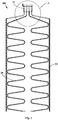
- Fig. 1 is a schematic rear view of a cold end heat exchanging device 200 according to one embodiment of the present invention.
- the embodiments of the present invention provide a cold end heat exchanging device 200 for a semiconductor refrigerator, which may include a cold end heat exchanging part 10 and a plurality of refrigerant pipelines 20.
- the cold end heat exchanging part 10 defines an inner cavity or pipeline for containing a refrigerant existing in both gas and liquid phases and is configured to allow the refrigerant to flow therein and undergo phase-change heat exchange.
- the plurality of refrigerant pipelines 20 are configured to allow the refrigerant to flow therein and undergo phase-change heat exchange.
- Each of the refrigerant pipelines 20 is provided with: an evaporation section 21 which is downwardly bent and extends in a vertical plane and has a closed tail end, and a connection section 22 which is upwardly bent and extends from a starting end of the evaporation section 21 and is connected to the inner cavity or pipeline. That is to say, the first end of each refrigerant pipeline 20 forming the opening end is connected to the lower portion of the inner cavity or pipeline, and each refrigerant pipeline 20 obliquely downwardly bent and extends from the first end thereof and terminates at the second end forming the closed end.
- evaporation sections 21 of at least some refrigerant pipelines 20 of the plurality of refrigerant pipelines 20 are arranged in the two vertical planes which are perpendicular to each other, at least one side wall and a rear wall of a liner 100 can perform heat exchange with the evaporation sections 21 of the refrigerant pipelines 20, so that the cold dissipation efficiency of the cold end heat exchanging device 200 and the energy efficiency of the semiconductor refrigerator are significantly improved, and the cold end heat exchanging device makes full use of the refrigerator structure, and takes up small space.
- the refrigerant poured into the cold end heat exchanging part 10 and the refrigerant pipelines 20 may be carbon dioxide or other refrigeration medium, and the pouring amount of the refrigerant may be measured by a test.
- the downwardly and extending structure of each of the refrigerant pipelines 20 should ensure that the liquid refrigerant can be free to flow in the pipeline by gravity.
- the cold end heat exchanging device 200 of the present embodiment works, the refrigerant is subjected to a gas-liquid phase change in the cold end heat exchanging part 10 and the refrigerant pipeline 20 for thermal cycling.
- the cold end heat exchanging part 10 of the cold end heat exchanging device 200 may have a flat rectangular cuboid shape, and the areas of a front surface and a rear surface, disposed opposite to each other, of the cold end heat exchanging part 10 is larger than the areas of the other surfaces, and the rear surface of the cold end heat exchanging part 10 is used as a heat transfer surface which is thermally connected to a cold source (e.g., the cold end of a semiconductor cooler), the thermal connection may be such that the outer surface is in direct contact with and abutted against the cold source or in contact with same via a thermally conductive layer, wherein the thermally conductive layer may be thermally conductive silica gel or graphite or the like coated between the outer surface and the cold source.
- a cold source e.g., the cold end of a semiconductor cooler
- the "thermal connection” or “thermal contact” in the present embodiment may be direct abutting and contact, and the heat transfer is carried out by means of heat conduction. If the abutted contact surface is coated with thermally conductive silicone grease (graphite or other medium), it may be considered to be part of the abutted contact surface as a thermally conductive layer for improving the thermal connection (or thermal contact).
- thermally conductive silicone grease graphite or other medium
- the evaporation sections 21 of at least some refrigerant pipelines 20 of the plurality of refrigerant pipelines 20 are arranged in two vertical planes perpendicular to each other, wherein the two vertical planes include a first plane perpendicular to the rear surface of the cold end heat exchanging part 10 and a second plane parallel to the rear surface of the cold end heat exchanging part 10, so that at least one side wall and a rear wall of the liner 100 perform heat exchange with the evaporation sections 21 of the refrigerant pipelines 20.
- the cold end heat exchanging part 10 of the cold end heat exchanging device 200 may be disposed between the rear wall of the liner 100 and the back 310 of a housing when the cold end heat exchanging device 200 of the embodiment of the present invention is applied to the semiconductor refrigerator. For example, a distance may be provided between the front surface of the cold end heat exchanging part 10 and the rear wall of the liner 100 to ensure that the heat is not conducted to the liner 100 during a power failure or an operational failure, causing an abnormal temperature.
- the rear surface of the cold end heat exchanging part 10 is abutted against the cold end of the semiconductor cooler, and the evaporation section 21 of each of the refrigerant pipelines 20 is abutted against the outer surface of the liner 100.
- the working process of the semiconductor refrigerator is as follows: when the semiconductor cooler is powered on and operates, the temperature of the cold end decreases, the temperature of the cold end heat exchanging part 10 correspondingly decreases due to the conduction, and the gaseous refrigerant therein undergoes phase change to be condensed when subjected to cold, to change into the liquid refrigerant at a low temperature; and the liquid refrigerant flows down due to gravity along the cavity of the refrigerant pipeline 20, and the condensed flown-down refrigerant is heated, undergoes phase change and is evaporated in the refrigerant pipeline 20 since it absorbs heat from the interior of the refrigerator to change into a gaseous state.
- the gaseous vapour will rise under the driving of the pressure of a heat source, and the gaseous refrigerant will rise to the cold end heat exchanging part 10 to continue to condense, thereby repeating the refrigeration, resulting in the lowered temperature of the storage compartment so that the cooling is achieved.
- the evaporation sections 21 of some refrigerant pipelines 20 of the plurality of refrigerant pipelines 20 are arranged in a third plane parallel to the first plane such that two side walls and a rear wall of the liner 100 respectively perform heat exchange with the evaporation sections 21 of the corresponding refrigerant pipelines 20.
- the evaporation section 21 of each of the refrigerant pipelines 20, of which the evaporation sections 21 are arranged in the second plane is located between the first plane and the third plane.
- the evaporation section 21 of each of the refrigerant pipelines 20, of which the evaporation sections 21 are arranged in the first plane, and the evaporation section 21 of each of the refrigerant pipelines 20, of which the evaporation sections 21 are arranged in the third plane, are both located on one side of the second plane.
- the number of refrigerant pipelines 20, of which the evaporation sections 21 are arranged in the second plane is two, and the refrigerant pipelines are symmetrically arranged with respect to a vertical geometrical symmetry plane.
- the number of refrigerant pipelines 20, of which the evaporation sections 21 are arranged in the first plane, and the number of refrigerant pipelines 20, of which the evaporation sections 21 are arranged in the third plane, are both one, and the refrigerant pipelines are symmetrically arranged with respect to the vertical geometrical symmetry plane, wherein the vertical geometrical symmetry plane is the vertical symmetry plane of the liner 100.
- the evaporation section 21 of each of the refrigerant pipelines 20, of which the evaporation sections 21 are arranged in the second plane has a projected length on a horizontal plane that is smaller than 1/2 of the width of the rear wall of the liner 100 of the semiconductor refrigerator and greater than 1/4 of the width of the rear wall of the liner 100, so that the evaporation sections 21 of the two refrigerant pipelines 20 are thermally connected to the left and right half portions of the outer surface of the rear wall of the liner 100, respectively.
- each evaporation section 21 In order to better transfer the cold of each evaporation section 21 to the liner 100 of the refrigerator, the thermal connection between the evaporation section 21 of each refrigerant pipeline 20 and the outer surface of the liner 100 is achieved by abutting the evaporation sections 21 of the refrigerant pipelines 20 against the outer surfaces of the rear wall and the two side walls of the liner 100, respectively.
- each evaporation section 21 may be abutted against a respective flat thermally conductive plate, and the flat thermally conductive plates are abutted against the rear wall and the two side walls of the liner 100, so that the liner 100 of the refrigerator is cooled more evenly.
- each of the refrigerant pipelines 20 may be selected from a copper tube, a stainless steel tube, an aluminum tube, etc., preferably a copper tube.
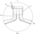
- the connection section 22 of the refrigerant pipeline 20, of which the evaporation section 21 is thermally connected to the side wall of the liner 100 may comprise a first segment 221 and a second segment 222, wherein the first segment 221 is in communication with the inner cavity or pipeline of the cold end heat exchanging part 10 and extends to the outside of the cold end heat exchanging part 10; and the second segment 222 is connected to the first segment 221, extends transversely and obliquely downwardly on the rear wall of the liner 100, and then is obliquely downwardly bent forwards to the side wall of the liner 100 to connect the evaporation section 21 of the corresponding refrigerant pipeline 20.
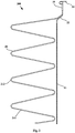
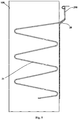
- the evaporation section 21 of each refrigerant pipeline 20 may include a plurality of vertically spaced straight pipe segments 211 and bent segments 212, each bent segment being used for connecting two adjacent straight pipe segments 211, wherein each of the straight pipe segments 211 is arranged obliquely at an angle of 10° to 70° with respect to the horizontal plane, to ensure that the liquid refrigerant is free to flow therein by gravity, and the bent segment 212 is preferably arranged in a "C" shape or is an arc-shaped section so that the evaporator section 21 is generally of an inclined "Z"-shaped structure.
- the semiconductor refrigerator of the embodiments of the present invention further comprises a plurality of retention steel wires 50 in order to prevent deformation of the evaporation section 21 of each of the refrigerant pipelines 20 to ensure efficient flow and heat exchange of the refrigerant within each of the refrigerant pipelines 20.
- Each of the retention steel wires 50 is disposed in the vertical direction.
- a pipe wall at an outer vertex (also referred to as a top hump) of each of the bent segments 212 on the same side of each of the refrigerant pipelines 20 is welded to a corresponding retention steel wire 50.
- the two retention steel wires 50 may be respectively fixed to two sides of the evaporation section 21 of a corresponding refrigerant pipeline 20, and each of the retention steel wires 50, at different locations along its length, is successively fixed to the top hump of each of the bent segments 212 on the corresponding side of the corresponding evaporation section 21. Further, other portions of each of the refrigerant pipelines 20 that are in contact with the respective retention steel wire 50 may be all welded to the retention steel wire 50.
- the cold end heat exchanging part 10 of the cold end heat exchanging device 200 may be a heat exchange copper block in which four stepped blind holes 11 extending in the vertical direction and a horizontal tube hole 12 communicating with the upper portion of each of the step blind holes 11 are provided to form a pipeline inside the cold end heat exchanging part 10.
- the upper end of each of the refrigerant pipelines 20 can be inserted into the corresponding stepped blind hole 11.
- the cold end heat exchanging device 200 further comprises a refrigerant pouring tube 30 having one end being in communication with the corresponding horizontal tube bore 12 and the other end being operatively open the normally closed end to receive the refrigerant poured from the outside, so as to pour the refrigerant into each of the refrigerant pipelines 20.
- the cold end heat exchanging part 10 of the cold end heat exchanging device 200 may be a cold end heat exchange box which defines an inner cavity or pipeline for containing a refrigerant existing in both gas and liquid phases and is configured to allow the refrigerant to undergo phase-change heat exchange.
- the connection section 22 of each of the refrigerant pipelines 20 is in communication with the lower portion of the inner cavity.
- the cold end heat exchanging device 200 may be further provided with a three-way device for pouring the refrigerant.
- the three-way device is located on the connection section 22 of one refrigerant pipeline 20 with the first and second ends thereof being used to communicate the corresponding two segments of the connection section 22 and the third end being configured to operatively open the normally closed end to receive the refrigerant poured from the outside.
- the use of the three-way device reduces the difficulty of the process of pouring the refrigerant and provides a means for maintaining.
- the semiconductor refrigerator may comprise: a liner 100, a semiconductor cooler, and a cold end heat exchanging device 200 in any of the above embodiments.
- the liner 100 has a storage compartment defined therein.
- the semiconductor cooler may be provided at the rear of the liner 100.
- the cold end heat exchanging device 200 may be mounted in such a way that the rear surface of the cold end heat exchanging part 10 thereof is thermally connected to a cold end of the semiconductor cooler, and the evaporation section 21 of each of the refrigerant pipelines 20 is abutted against the outer surface of the inner 100 for transferring the cold from the cold end to the storage compartment.
- the structure of the cabinet of the semiconductor refrigerator generally further comprises: a housing, a door 500 and an insulation layer.
- refrigerator cabinet structures There are two types of refrigerator cabinet structures, one is of an assembled type, that is, an integrated cabinet assembled by a top cover, a back 310, left and right side plates 320, an underlying plate, etc.
- the other is of a monolithic type, that is, the top cover and the left and right side plates 320 are rolled into a "U" shape as required, which is referred to as a U-shell, and are spot welded with the back 310 and the underlying plate of the housing to form the cabinet.
- the semiconductor refrigerator of the embodiment of the present invention preferably uses the monolithic housing, that is, the housing includes a U-shell and a back 310, wherein the U-shell is disposed on the outer sides of the side walls and the top wall of the liner 100, and the back 310 of the housing and the rear wall of the liner 100 defines an installation space.
- the semiconductor cooler and the cold end heat exchanging device 200 may be selectively arranged in the installation space defined by the outer side of the rear wall of the liner 100 and the back 310 of the housing, and the front surface of the cold end heat exchanging part 10 is opposed to the rear wall of the liner 100.
- a distance may be provided between the front surface of the cold end heat exchanging part 10 and the rear wall of the liner 100 to ensure that the heat of a hot end is not conducted to the liner 100 during a power failure or an operational failure, causing an abnormal temperature.
- the semiconductor refrigerator of this embodiment may further comprise a hot end heat exchanging device 400, which is thermally connected to the hot end of the semiconductor cooler for diffusing the heat generated by the hot end to the surrounding environment.
- the hot end heat exchanging device 400 comprises a hot end heat exchanging part and a heat dissipation pipeline 420.
- the hot end heat exchanging part defines an inner cavity for containing a refrigerant existing in both gas and liquid phases and configured to allow the refrigerant to undergo phase-change heat exchange.
- the heat dissipation pipeline 420 is configured to allow the refrigerant to flow therein and undergo phase-change heat exchange, and the first end of each heat dissipation pipeline 420 that forms the opening end is connected to the upper portion of the inner cavity of the hot end heat exchanging part, and each heat dissipation pipeline 420 obliquely upwardly bent and extends from the first end thereof and terminates at the second end forming the closed end.
- Some of pipe sections of the heat dissipation pipeline 420 may be abutted against the inner surface of the housing of the refrigerator, such as some of pipe sections of some of the heat dissipation pipelines 420 are abutted against the inner surface of the back 310 of the housing, and some of pipe sections of the remaining heat dissipation pipelines 420 are abutted against the inner surfaces of the two side plates 320 of the housing, such that the housing is used to diffuse heat to the surrounding environment.
- the refrigerant poured in the hot end heat exchanging part may be water or other refrigerant, the state of which is a co-existing state of gas and liquid phases, and the temperature of the hot end of the semiconductor cooler rises when being powered on and working.
- the hot end of the hot refrigerant performs heat exchange with the hot end heat exchanging part
- the hot end heat exchanging part forms an evaporator for changing the refrigerant to be in a gaseous state
- the gaseous refrigerant rises up along the refrigerant pipeline 20 under the pressure of the heat source, to transfer the heat to the housing of the refrigerator, then the heat is transferred to the external space through the natural convection
- the heat dissipation pipeline 420 forms a condenser
- the refrigerant is condensed into the liquid state after release of heat, flows back to the hot end heat exchanging part by gravity, and re-absorbs the heat from the hot end to evaporate same to form a thermal cycle.
- the structure thereof may be such that the semiconductor cooler is arranged in the space between the rear wall of the liner 100 of the refrigerator and the back 310 of the housing of the refrigerator, the rear wall of the cold end heat exchanging part of the cold end heat exchanging device 200 is connected to the cold end of the semiconductor cooler, and the refrigerant pipeline 20 is abutted against the liner 100 of the refrigerator for cooling the storage cavity.
- the hot end of the semiconductor cooler conducts the heat from the hot end to a lower position through a vertically downwardly arranged heat bridge device, and the upper end of the heat bridge device is connected to the hot end of the semiconductor cooler, the hot end heat exchanging part of the hot end heat exchanging device 400 can be thermally connected to the hot end of the semiconductor cooler via the lower end of the heat bridge device to provide a greater upwardly extending space for the heat dissipation pipeline 420.
- other forms of the hot end heat exchanging device 400 may also be used by those skilled in the art, for example, using a hot end heat exchanging device 400 comprising a heat pipe, a fin and a fan.
Landscapes
- Engineering & Computer Science (AREA)
- Physics & Mathematics (AREA)
- Mechanical Engineering (AREA)
- Thermal Sciences (AREA)
- General Engineering & Computer Science (AREA)
- Chemical & Material Sciences (AREA)
- Combustion & Propulsion (AREA)
- Devices That Are Associated With Refrigeration Equipment (AREA)
Claims (9)
- Dispositif échangeur de chaleur d'extrémité froide (200) pour un réfrigérateur à semi-conducteur, comprenant :une pièce d'échange de chaleur d'extrémité froide (10), laquelle définit une cavité ou une conduite interne destinée à contenir un fluide frigorigène existant dans les deux phases gazeuse et liquide et laquelle est conçue pour permettre au fluide frigorigène de circuler dans ledit dispositif échangeur de chaleur d'extrémité froide et de subir un échange de chaleur à changement de phase ; etune pluralité de conduites de fluide frigorigène (20), conçues pour permettre au fluide frigorigène de s'écouler et de subir un échange de chaleur à changement de phase, la conduite de fluide frigorigène (20) respective comportant : une section d'évaporation (21), laquelle est courbée pour se diriger vers une première direction et laquelle s'étend dans un plan et laquelle comporte une extrémité arrière fermée, et une section de raccordement (22), laquelle est courbée pour se diriger vers une deuxième direction, opposée à la première direction et laquelle s'étend à partir d'une extrémité de départ de la section d'évaporation (21) et laquelle est raccordée à la cavité ou à la conduite interne ; etles sections d'évaporation (21) d'au moins une partie de la pluralité de conduites de fluide frigorigène (20) étant agencées dans deux plans, lesquels sont perpendiculaires l'un à l'autre ;la section d'évaporation (21) de la conduite de fluide frigorigène (20) respective comportant :une pluralité de segments de tube droit, disposés dans la première direction à des intervalles, le segment de tube droit respectif étant disposé obliquement à un angle de 10° à 70° par rapport à un plan de référence perpendiculaire à la première direction ; etdes segments courbés, le segment courbé respectif raccordant deux segments de tube droit adjacents ;caractérisé en ce quele dispositif d'échange de chaleur d'extrémité froide (200) comprend en outre :une pluralité de fils d'acier de retenue (50), disposés dans la première direction ; etune paroi de tube, à un sommet extérieur du segment courbé respectif du même côté de la conduite de fluide frigorigène (20) respective, laquelle est soudée à l'un des fils d'acier de retenue (50).
- Dispositif d'échange de chaleur d'extrémité froide (200) selon la revendication 1, caractérisé en ce que
la pièce d'échange de chaleur d'extrémité froide (10) présente une forme parallélépipédique plate dotée des zones d'une surface avant et d'une surface arrière opposées l'une à l'autre, étant plus grandes que les zones des autres surfaces et la surface arrière de la pièce d'échange de chaleur d'extrémité froide (10) sert de surface d'échange de chaleur, laquelle est raccordée thermiquement à une source froide. - Dispositif d'échange de chaleur d'extrémité froide (200) selon la revendication 1 ou 2, caractérisé en ce que
les deux plans comprennent un premier plan perpendiculaire à la surface arrière de la pièce d'échange de chaleur d'extrémité froide (10) et un deuxième plan parallèle à la surface arrière de la pièce d'échange de chaleur d'extrémité froide (10). - Dispositif d'échange de chaleur d'extrémité froide (200) selon la revendication 3, caractérisé en ce que
les sections d'évaporation (21) des certaines de la pluralité de conduites de fluide frigorigène (20) sont disposées dans un troisième plan, parallèle au premier plan. - Dispositif d'échange de chaleur d'extrémité froide (200) selon la revendication 4, caractérisé en ce que
la section d'évaporation (21) de la conduite de fluide frigorigène (20) respective, dont la section d'évaporation (21) est disposée dans le deuxième plan, est située entre les premier et troisième plans ; et
la section d'évaporation (21) de la conduite de fluide frigorigène (20) respective, dont la section d'évaporation (21) est disposée dans le premier plan et la section d'évaporation (21) de la conduite de fluide frigorigène (20) respective, dont la section d'évaporation (21) est disposée dans le troisième plan, étant toutes deux situées d'un côté du deuxième plan. - Dispositif d'échange de chaleur d'extrémité froide (200) selon la revendication 5, caractérisé en ce que
le nombre de conduites de fluide frigorigène (20), dont les sections d'évaporation (21) sont disposées dans le deuxième plan, est de deux et les conduites de fluide frigorigène (20) sont disposées symétriquement par rapport à un plan de symétrie géométrique. - Dispositif d'échange de chaleur d'extrémité froide (200) selon la revendication 6, caractérisé en ce que
le nombre de conduites de fluide frigorigène (20), dont les sections d'évaporation (21) sont disposées dans le premier plan et le nombre de conduites de fluide frigorigène (20), dont les sections d'évaporation (21) sont disposées dans le troisième plan, est respectivement d'une et les conduites de fluide frigorigène (20) sont disposées symétriquement par rapport au plan de symétrie géométrique. - Dispositif d'échange de chaleur d'extrémité froide (200) selon la revendication 7, caractérisé en ce que
la section d'évaporation (21) de la conduite de fluide frigorigène (20) respective, dont la section d'évaporation (21) est disposée dans le deuxième plan, comporte une longueur, projetée sur un plan perpendiculaire aux premier et deuxième plans, inférieure à 1/2 de la largeur d'une paroi arrière d'un réservoir intérieur (100) du réfrigérateur à semi-conducteur et supérieure à 1/4 de la largeur de la paroi arrière du réservoir intérieur (100) ;
la section d'évaporation (21) de la conduite de fluide frigorigène (20) respective, dont la section d'évaporation (21) est disposée dans le premier plan et la section d'évaporation (21) de la conduite de fluide frigorigène (20) respective, dont la section d'évaporation (21) est disposée dans le troisième plan, les deux dites sections d'évaporation comportant une longueur, projetée sur un plan perpendiculaire aux premier et deuxième plans, laquelle est inférieure à la largeur d'une paroi latérale du réservoir intérieur (100) du réfrigérateur à semi-conducteur et à la 1/2 de la largeur de la paroi latérale du réservoir intérieur (100). - Réfrigérateur à semi-conducteur, comprenant :un réservoir intérieur (100), comportant un compartiment de stockage défini à l'intérieur dudit réservoir intérieur ;un refroidisseur à semi-conducteur, disposé derrière ledit réservoir intérieur (100) ; etun dispositif d'échange de chaleur d'extrémité froide (200) selon l'une quelconque des revendications 1 à 8, lequel est monté de telle sorte que la surface arrière de la pièce d'échange de chaleur d'extrémité froide (10) est raccordée thermiquement à une extrémité froide du refroidisseur à semi-conducteur et la section d'évaporation (21) de la conduite de fluide frigorigène (20) respective vient en butée contre une surface extérieure de l'intérieur pour transférer le froid de l'extrémité froide vers le compartiment de stockage.
Applications Claiming Priority (2)
| Application Number | Priority Date | Filing Date | Title |
|---|---|---|---|
| CN201410777708.8A CN104534781B (zh) | 2014-12-15 | 2014-12-15 | 冷端换热装置及半导体制冷冰箱 |
| PCT/CN2015/090985 WO2016095587A1 (fr) | 2014-12-15 | 2015-09-28 | Dispositif d'échange de chaleur d'extrémité froide et réfrigérateur à semi-conducteurs |
Publications (3)
| Publication Number | Publication Date |
|---|---|
| EP3220080A1 EP3220080A1 (fr) | 2017-09-20 |
| EP3220080A4 EP3220080A4 (fr) | 2017-09-20 |
| EP3220080B1 true EP3220080B1 (fr) | 2018-09-12 |
Family
ID=52850355
Family Applications (1)
| Application Number | Title | Priority Date | Filing Date |
|---|---|---|---|
| EP15869098.2A Active EP3220080B1 (fr) | 2014-12-15 | 2015-09-28 | Dispositif d'échange de chaleur d'extrémité froide et réfrigérateur à semi-conducteurs |
Country Status (4)
| Country | Link |
|---|---|
| US (1) | US10197309B2 (fr) |
| EP (1) | EP3220080B1 (fr) |
| CN (1) | CN104534781B (fr) |
| WO (1) | WO2016095587A1 (fr) |
Families Citing this family (9)
| Publication number | Priority date | Publication date | Assignee | Title |
|---|---|---|---|---|
| CN104534781B (zh) * | 2014-12-15 | 2016-11-23 | 青岛海尔股份有限公司 | 冷端换热装置及半导体制冷冰箱 |
| CN106288592A (zh) * | 2015-05-14 | 2017-01-04 | 青岛海尔智能技术研发有限公司 | 冰箱 |
| KR102882225B1 (ko) * | 2017-02-21 | 2025-11-07 | 엘지전자 주식회사 | 냉장고 |
| WO2018183731A1 (fr) * | 2017-03-29 | 2018-10-04 | Rockwell Collins, Inc. | Unité cuisine-bar refroidie par liquide |
| US10718558B2 (en) * | 2017-12-11 | 2020-07-21 | Global Cooling, Inc. | Independent auxiliary thermosiphon for inexpensively extending active cooling to additional freezer interior walls |
| CN112673221B (zh) * | 2018-09-11 | 2022-06-07 | 普和希控股公司 | 制冷装置 |
| CN112577229A (zh) * | 2019-09-29 | 2021-03-30 | 青岛海尔电冰箱有限公司 | 冰箱 |
| CN110739883B (zh) * | 2019-10-25 | 2022-08-16 | 四川德胜集团钒钛有限公司 | 一种余热发电装置 |
| CN114183976A (zh) * | 2020-09-15 | 2022-03-15 | 青岛海尔电冰箱有限公司 | 冰箱 |
Family Cites Families (21)
| Publication number | Priority date | Publication date | Assignee | Title |
|---|---|---|---|---|
| US3181310A (en) * | 1963-09-03 | 1965-05-04 | Walter D Ammons | Refrigerating apparatus with holdover means |
| US5653111A (en) * | 1993-07-07 | 1997-08-05 | Hydrocool Pty. Ltd. | Thermoelectric refrigeration with liquid heat exchange |
| US6776220B1 (en) * | 1999-08-19 | 2004-08-17 | Space Systems/Loral, Inc | Spacecraft radiator system using crossing heat pipes |
| US6272867B1 (en) * | 1999-09-22 | 2001-08-14 | The Coca-Cola Company | Apparatus using stirling cooler system and methods of use |
| US20010023762A1 (en) * | 2000-01-11 | 2001-09-27 | Sagal E. Mikhail | Heat pipe spreader construction |
| CN2472155Y (zh) * | 2001-03-16 | 2002-01-16 | 合肥美菱股份有限公司 | 高效半导体制冷设备 |
| JP2004537705A (ja) * | 2001-07-20 | 2004-12-16 | エイ・エル・エム・エイ テクノロジー コーポレーション リミテッド | 熱交換器及び熱交換マニホールド |
| US6658857B1 (en) * | 2003-02-20 | 2003-12-09 | Hatho M. George | Portable thermoelectric cooling and heating appliance device and method of using |
| CN2906522Y (zh) * | 2006-05-27 | 2007-05-30 | 广东新宝电器股份有限公司 | 电子冰箱的热管装置 |
| CN101418998B (zh) * | 2008-11-03 | 2011-02-02 | 吴鸿平 | 半导体吸收式制冷系统 |
| US20100154452A1 (en) * | 2008-11-30 | 2010-06-24 | Mccann Kevin | Portable electric cooler |
| CN202229500U (zh) * | 2011-09-15 | 2012-05-23 | 陈志明 | 无压缩机式电冰箱 |
| WO2013169774A2 (fr) * | 2012-05-07 | 2013-11-14 | Phononic Devices, Inc. | Composant d'échangeur de chaleur thermoélectrique comprenant un couvercle d'étalement de la chaleur protecteur et une résistance d'interface thermique optimale |
| US20130291555A1 (en) * | 2012-05-07 | 2013-11-07 | Phononic Devices, Inc. | Thermoelectric refrigeration system control scheme for high efficiency performance |
| CN103199316B (zh) * | 2013-04-19 | 2015-12-02 | 安科智慧城市技术(中国)有限公司 | 电池组及其散热结构 |
| CN203421876U (zh) * | 2013-08-29 | 2014-02-05 | 顺德职业技术学院 | 一种热管电子冰箱 |
| CN203421877U (zh) * | 2013-08-29 | 2014-02-05 | 顺德职业技术学院 | 一种内藏式热管冰箱 |
| US10520230B2 (en) * | 2013-09-16 | 2019-12-31 | Phononic, Inc. | Enhanced heat transport systems for cooling chambers and surfaces |
| CN105940280B (zh) * | 2014-01-28 | 2019-07-16 | 弗诺尼克设备公司 | 用于减轻热虹吸管蒸发器或冷凝器中的高热通量状况的机构 |
| CN203810826U (zh) | 2014-03-28 | 2014-09-03 | 海尔集团公司 | 冰箱 |
| CN104534781B (zh) | 2014-12-15 | 2016-11-23 | 青岛海尔股份有限公司 | 冷端换热装置及半导体制冷冰箱 |
-
2014
- 2014-12-15 CN CN201410777708.8A patent/CN104534781B/zh active Active
-
2015
- 2015-09-28 WO PCT/CN2015/090985 patent/WO2016095587A1/fr not_active Ceased
- 2015-09-28 US US15/536,512 patent/US10197309B2/en active Active
- 2015-09-28 EP EP15869098.2A patent/EP3220080B1/fr active Active
Non-Patent Citations (1)
| Title |
|---|
| None * |
Also Published As
| Publication number | Publication date |
|---|---|
| EP3220080A1 (fr) | 2017-09-20 |
| CN104534781B (zh) | 2016-11-23 |
| US20170328611A1 (en) | 2017-11-16 |
| CN104534781A (zh) | 2015-04-22 |
| US10197309B2 (en) | 2019-02-05 |
| EP3220080A4 (fr) | 2017-09-20 |
| WO2016095587A1 (fr) | 2016-06-23 |
Similar Documents
| Publication | Publication Date | Title |
|---|---|---|
| EP3220080B1 (fr) | Dispositif d'échange de chaleur d'extrémité froide et réfrigérateur à semi-conducteurs | |
| EP3220081B1 (fr) | Réfrigérateur à semi-conducteurs | |
| CN104534727B (zh) | 热端换热装置及半导体制冷冰箱 | |
| CN104329828B (zh) | 半导体制冷冰箱及其热端换热装置 | |
| CN104329850B (zh) | 半导体制冷冰箱及其热端换热装置 | |
| CN104329871A (zh) | 半导体制冷冰箱及其冷端换热装置 | |
| CN108344206A (zh) | 蒸发器组件和冰箱 | |
| CN102128552A (zh) | 单面波浪板式脉动热管 | |
| CN104329866B (zh) | 半导体制冷冰箱及其冷端换热装置 | |
| CN104344641B (zh) | 半导体制冷冰箱及其热端换热装置 | |
| CN104329868A (zh) | 半导体制冷冰箱及其冷端换热装置 | |
| CN205537254U (zh) | 换热装置及具有该换热装置的半导体制冷冰箱 | |
| US10612822B2 (en) | Bent pipe with retention member and semiconductor refrigerator having same | |
| CN104329829B (zh) | 半导体制冷冰箱及其热端换热装置 | |
| CN216522077U (zh) | 空调器 | |
| CN205351567U (zh) | 空调室外机 | |
| WO2022091908A1 (fr) | Échangeur de chaleur et réfrigérateur | |
| CN219511096U (zh) | 冰箱 | |
| CN216592921U (zh) | 热管组件及制冷设备 | |
| CN201322475Y (zh) | 一种冰箱蒸发器 | |
| JP2007333270A (ja) | ヒートポンプ熱源機 | |
| KR200325590Y1 (ko) | 열교환파이프 | |
| CN204421417U (zh) | 换热装置及半导体制冷冰箱 | |
| CN105485969A (zh) | 换热装置及具有该换热装置的半导体制冷冰箱 | |
| CN201322474Y (zh) | 冰箱用蒸发器 |
Legal Events
| Date | Code | Title | Description |
|---|---|---|---|
| PUAI | Public reference made under article 153(3) epc to a published international application that has entered the european phase |
Free format text: ORIGINAL CODE: 0009012 |
|
| 17P | Request for examination filed |
Effective date: 20170615 |
|
| A4 | Supplementary search report drawn up and despatched |
Effective date: 20170817 |
|
| AK | Designated contracting states |
Kind code of ref document: A1 Designated state(s): AL AT BE BG CH CY CZ DE DK EE ES FI FR GB GR HR HU IE IS IT LI LT LU LV MC MK MT NL NO PL PT RO RS SE SI SK SM TR |
|
| AX | Request for extension of the european patent |
Extension state: BA ME |
|
| 17Q | First examination report despatched |
Effective date: 20170901 |
|
| DAV | Request for validation of the european patent (deleted) | ||
| DAX | Request for extension of the european patent (deleted) | ||
| GRAP | Despatch of communication of intention to grant a patent |
Free format text: ORIGINAL CODE: EPIDOSNIGR1 |
|
| INTG | Intention to grant announced |
Effective date: 20180404 |
|
| GRAS | Grant fee paid |
Free format text: ORIGINAL CODE: EPIDOSNIGR3 |
|
| GRAA | (expected) grant |
Free format text: ORIGINAL CODE: 0009210 |
|
| AK | Designated contracting states |
Kind code of ref document: B1 Designated state(s): AL AT BE BG CH CY CZ DE DK EE ES FI FR GB GR HR HU IE IS IT LI LT LU LV MC MK MT NL NO PL PT RO RS SE SI SK SM TR |
|
| REG | Reference to a national code |
Ref country code: GB Ref legal event code: FG4D |
|
| REG | Reference to a national code |
Ref country code: CH Ref legal event code: EP |
|
| REG | Reference to a national code |
Ref country code: IE Ref legal event code: FG4D |
|
| REG | Reference to a national code |
Ref country code: DE Ref legal event code: R096 Ref document number: 602015016390 Country of ref document: DE |
|
| REG | Reference to a national code |
Ref country code: AT Ref legal event code: REF Ref document number: 1041076 Country of ref document: AT Kind code of ref document: T Effective date: 20181015 |
|
| REG | Reference to a national code |
Ref country code: FR Ref legal event code: PLFP Year of fee payment: 4 |
|
| REG | Reference to a national code |
Ref country code: NL Ref legal event code: MP Effective date: 20180912 |
|
| REG | Reference to a national code |
Ref country code: LT Ref legal event code: MG4D |
|
| PG25 | Lapsed in a contracting state [announced via postgrant information from national office to epo] |
Ref country code: GR Free format text: LAPSE BECAUSE OF FAILURE TO SUBMIT A TRANSLATION OF THE DESCRIPTION OR TO PAY THE FEE WITHIN THE PRESCRIBED TIME-LIMIT Effective date: 20181213 Ref country code: RS Free format text: LAPSE BECAUSE OF FAILURE TO SUBMIT A TRANSLATION OF THE DESCRIPTION OR TO PAY THE FEE WITHIN THE PRESCRIBED TIME-LIMIT Effective date: 20180912 Ref country code: BG Free format text: LAPSE BECAUSE OF FAILURE TO SUBMIT A TRANSLATION OF THE DESCRIPTION OR TO PAY THE FEE WITHIN THE PRESCRIBED TIME-LIMIT Effective date: 20181212 Ref country code: NO Free format text: LAPSE BECAUSE OF FAILURE TO SUBMIT A TRANSLATION OF THE DESCRIPTION OR TO PAY THE FEE WITHIN THE PRESCRIBED TIME-LIMIT Effective date: 20181212 Ref country code: LT Free format text: LAPSE BECAUSE OF FAILURE TO SUBMIT A TRANSLATION OF THE DESCRIPTION OR TO PAY THE FEE WITHIN THE PRESCRIBED TIME-LIMIT Effective date: 20180912 Ref country code: FI Free format text: LAPSE BECAUSE OF FAILURE TO SUBMIT A TRANSLATION OF THE DESCRIPTION OR TO PAY THE FEE WITHIN THE PRESCRIBED TIME-LIMIT Effective date: 20180912 Ref country code: SE Free format text: LAPSE BECAUSE OF FAILURE TO SUBMIT A TRANSLATION OF THE DESCRIPTION OR TO PAY THE FEE WITHIN THE PRESCRIBED TIME-LIMIT Effective date: 20180912 |
|
| PG25 | Lapsed in a contracting state [announced via postgrant information from national office to epo] |
Ref country code: AL Free format text: LAPSE BECAUSE OF FAILURE TO SUBMIT A TRANSLATION OF THE DESCRIPTION OR TO PAY THE FEE WITHIN THE PRESCRIBED TIME-LIMIT Effective date: 20180912 Ref country code: LV Free format text: LAPSE BECAUSE OF FAILURE TO SUBMIT A TRANSLATION OF THE DESCRIPTION OR TO PAY THE FEE WITHIN THE PRESCRIBED TIME-LIMIT Effective date: 20180912 Ref country code: HR Free format text: LAPSE BECAUSE OF FAILURE TO SUBMIT A TRANSLATION OF THE DESCRIPTION OR TO PAY THE FEE WITHIN THE PRESCRIBED TIME-LIMIT Effective date: 20180912 |
|
| REG | Reference to a national code |
Ref country code: AT Ref legal event code: MK05 Ref document number: 1041076 Country of ref document: AT Kind code of ref document: T Effective date: 20180912 |
|
| PG25 | Lapsed in a contracting state [announced via postgrant information from national office to epo] |
Ref country code: EE Free format text: LAPSE BECAUSE OF FAILURE TO SUBMIT A TRANSLATION OF THE DESCRIPTION OR TO PAY THE FEE WITHIN THE PRESCRIBED TIME-LIMIT Effective date: 20180912 Ref country code: PL Free format text: LAPSE BECAUSE OF FAILURE TO SUBMIT A TRANSLATION OF THE DESCRIPTION OR TO PAY THE FEE WITHIN THE PRESCRIBED TIME-LIMIT Effective date: 20180912 Ref country code: IS Free format text: LAPSE BECAUSE OF FAILURE TO SUBMIT A TRANSLATION OF THE DESCRIPTION OR TO PAY THE FEE WITHIN THE PRESCRIBED TIME-LIMIT Effective date: 20190112 Ref country code: CZ Free format text: LAPSE BECAUSE OF FAILURE TO SUBMIT A TRANSLATION OF THE DESCRIPTION OR TO PAY THE FEE WITHIN THE PRESCRIBED TIME-LIMIT Effective date: 20180912 Ref country code: ES Free format text: LAPSE BECAUSE OF FAILURE TO SUBMIT A TRANSLATION OF THE DESCRIPTION OR TO PAY THE FEE WITHIN THE PRESCRIBED TIME-LIMIT Effective date: 20180912 Ref country code: IT Free format text: LAPSE BECAUSE OF FAILURE TO SUBMIT A TRANSLATION OF THE DESCRIPTION OR TO PAY THE FEE WITHIN THE PRESCRIBED TIME-LIMIT Effective date: 20180912 Ref country code: RO Free format text: LAPSE BECAUSE OF FAILURE TO SUBMIT A TRANSLATION OF THE DESCRIPTION OR TO PAY THE FEE WITHIN THE PRESCRIBED TIME-LIMIT Effective date: 20180912 Ref country code: NL Free format text: LAPSE BECAUSE OF FAILURE TO SUBMIT A TRANSLATION OF THE DESCRIPTION OR TO PAY THE FEE WITHIN THE PRESCRIBED TIME-LIMIT Effective date: 20180912 Ref country code: AT Free format text: LAPSE BECAUSE OF FAILURE TO SUBMIT A TRANSLATION OF THE DESCRIPTION OR TO PAY THE FEE WITHIN THE PRESCRIBED TIME-LIMIT Effective date: 20180912 |
|
| REG | Reference to a national code |
Ref country code: CH Ref legal event code: PL |
|
| PG25 | Lapsed in a contracting state [announced via postgrant information from national office to epo] |
Ref country code: SK Free format text: LAPSE BECAUSE OF FAILURE TO SUBMIT A TRANSLATION OF THE DESCRIPTION OR TO PAY THE FEE WITHIN THE PRESCRIBED TIME-LIMIT Effective date: 20180912 Ref country code: SM Free format text: LAPSE BECAUSE OF FAILURE TO SUBMIT A TRANSLATION OF THE DESCRIPTION OR TO PAY THE FEE WITHIN THE PRESCRIBED TIME-LIMIT Effective date: 20180912 Ref country code: PT Free format text: LAPSE BECAUSE OF FAILURE TO SUBMIT A TRANSLATION OF THE DESCRIPTION OR TO PAY THE FEE WITHIN THE PRESCRIBED TIME-LIMIT Effective date: 20190112 |
|
| REG | Reference to a national code |
Ref country code: BE Ref legal event code: MM Effective date: 20180930 |
|
| REG | Reference to a national code |
Ref country code: DE Ref legal event code: R097 Ref document number: 602015016390 Country of ref document: DE |
|
| REG | Reference to a national code |
Ref country code: IE Ref legal event code: MM4A |
|
| PG25 | Lapsed in a contracting state [announced via postgrant information from national office to epo] |
Ref country code: LU Free format text: LAPSE BECAUSE OF NON-PAYMENT OF DUE FEES Effective date: 20180928 |
|
| PLBE | No opposition filed within time limit |
Free format text: ORIGINAL CODE: 0009261 |
|
| STAA | Information on the status of an ep patent application or granted ep patent |
Free format text: STATUS: NO OPPOSITION FILED WITHIN TIME LIMIT |
|
| PG25 | Lapsed in a contracting state [announced via postgrant information from national office to epo] |
Ref country code: DK Free format text: LAPSE BECAUSE OF FAILURE TO SUBMIT A TRANSLATION OF THE DESCRIPTION OR TO PAY THE FEE WITHIN THE PRESCRIBED TIME-LIMIT Effective date: 20180912 Ref country code: MC Free format text: LAPSE BECAUSE OF FAILURE TO SUBMIT A TRANSLATION OF THE DESCRIPTION OR TO PAY THE FEE WITHIN THE PRESCRIBED TIME-LIMIT Effective date: 20180912 Ref country code: IE Free format text: LAPSE BECAUSE OF NON-PAYMENT OF DUE FEES Effective date: 20180928 |
|
| 26N | No opposition filed |
Effective date: 20190613 |
|
| PG25 | Lapsed in a contracting state [announced via postgrant information from national office to epo] |
Ref country code: LI Free format text: LAPSE BECAUSE OF NON-PAYMENT OF DUE FEES Effective date: 20180930 Ref country code: BE Free format text: LAPSE BECAUSE OF NON-PAYMENT OF DUE FEES Effective date: 20180930 Ref country code: SI Free format text: LAPSE BECAUSE OF FAILURE TO SUBMIT A TRANSLATION OF THE DESCRIPTION OR TO PAY THE FEE WITHIN THE PRESCRIBED TIME-LIMIT Effective date: 20180912 Ref country code: CH Free format text: LAPSE BECAUSE OF NON-PAYMENT OF DUE FEES Effective date: 20180930 |
|
| PG25 | Lapsed in a contracting state [announced via postgrant information from national office to epo] |
Ref country code: MT Free format text: LAPSE BECAUSE OF NON-PAYMENT OF DUE FEES Effective date: 20180928 |
|
| PG25 | Lapsed in a contracting state [announced via postgrant information from national office to epo] |
Ref country code: TR Free format text: LAPSE BECAUSE OF FAILURE TO SUBMIT A TRANSLATION OF THE DESCRIPTION OR TO PAY THE FEE WITHIN THE PRESCRIBED TIME-LIMIT Effective date: 20180912 |
|
| PG25 | Lapsed in a contracting state [announced via postgrant information from national office to epo] |
Ref country code: CY Free format text: LAPSE BECAUSE OF FAILURE TO SUBMIT A TRANSLATION OF THE DESCRIPTION OR TO PAY THE FEE WITHIN THE PRESCRIBED TIME-LIMIT Effective date: 20180912 Ref country code: MK Free format text: LAPSE BECAUSE OF NON-PAYMENT OF DUE FEES Effective date: 20180912 Ref country code: HU Free format text: LAPSE BECAUSE OF FAILURE TO SUBMIT A TRANSLATION OF THE DESCRIPTION OR TO PAY THE FEE WITHIN THE PRESCRIBED TIME-LIMIT; INVALID AB INITIO Effective date: 20150928 |
|
| PGFP | Annual fee paid to national office [announced via postgrant information from national office to epo] |
Ref country code: DE Payment date: 20250916 Year of fee payment: 11 |
|
| PGFP | Annual fee paid to national office [announced via postgrant information from national office to epo] |
Ref country code: GB Payment date: 20250919 Year of fee payment: 11 |
|
| PGFP | Annual fee paid to national office [announced via postgrant information from national office to epo] |
Ref country code: FR Payment date: 20250929 Year of fee payment: 11 |