EP3219574A1 - Method and system for determining a vertical profile of a rail surface - Google Patents
Method and system for determining a vertical profile of a rail surface Download PDFInfo
- Publication number
- EP3219574A1 EP3219574A1 EP16205328.4A EP16205328A EP3219574A1 EP 3219574 A1 EP3219574 A1 EP 3219574A1 EP 16205328 A EP16205328 A EP 16205328A EP 3219574 A1 EP3219574 A1 EP 3219574A1
- Authority
- EP
- European Patent Office
- Prior art keywords
- signal
- vertical
- vertical acceleration
- domain
- rail
- Prior art date
- Legal status (The legal status is an assumption and is not a legal conclusion. Google has not performed a legal analysis and makes no representation as to the accuracy of the status listed.)
- Granted
Links
- 238000000034 method Methods 0.000 title claims abstract description 29
- 230000001133 acceleration Effects 0.000 claims abstract description 44
- 238000012545 processing Methods 0.000 claims abstract description 8
- 238000004088 simulation Methods 0.000 claims abstract description 5
- 238000012544 monitoring process Methods 0.000 claims description 18
- 230000010354 integration Effects 0.000 claims description 5
- 238000004458 analytical method Methods 0.000 claims description 4
- 238000001914 filtration Methods 0.000 claims description 3
- 238000006073 displacement reaction Methods 0.000 description 12
- 230000007547 defect Effects 0.000 description 10
- 238000004891 communication Methods 0.000 description 3
- 238000013016 damping Methods 0.000 description 3
- 238000012423 maintenance Methods 0.000 description 3
- 239000000725 suspension Substances 0.000 description 3
- 239000004606 Fillers/Extenders Substances 0.000 description 2
- 230000036541 health Effects 0.000 description 2
- 238000005259 measurement Methods 0.000 description 2
- 101100268665 Caenorhabditis elegans acc-1 gene Proteins 0.000 description 1
- 230000002950 deficient Effects 0.000 description 1
- 238000001514 detection method Methods 0.000 description 1
- 230000009977 dual effect Effects 0.000 description 1
- 230000006872 improvement Effects 0.000 description 1
- 230000003993 interaction Effects 0.000 description 1
- 230000003137 locomotive effect Effects 0.000 description 1
- 238000010295 mobile communication Methods 0.000 description 1
- 230000008569 process Effects 0.000 description 1
- 238000003672 processing method Methods 0.000 description 1
- 230000008439 repair process Effects 0.000 description 1
- 230000004044 response Effects 0.000 description 1
Images


Classifications
-
- B—PERFORMING OPERATIONS; TRANSPORTING
- B61—RAILWAYS
- B61K—AUXILIARY EQUIPMENT SPECIALLY ADAPTED FOR RAILWAYS, NOT OTHERWISE PROVIDED FOR
- B61K9/00—Railway vehicle profile gauges; Detecting or indicating overheating of components; Apparatus on locomotives or cars to indicate bad track sections; General design of track recording vehicles
- B61K9/08—Measuring installations for surveying permanent way
-
- B—PERFORMING OPERATIONS; TRANSPORTING
- B61—RAILWAYS
- B61L—GUIDING RAILWAY TRAFFIC; ENSURING THE SAFETY OF RAILWAY TRAFFIC
- B61L23/00—Control, warning, or like safety means along the route or between vehicles or vehicle trains
- B61L23/04—Control, warning, or like safety means along the route or between vehicles or vehicle trains for monitoring the mechanical state of the route
- B61L23/042—Track changes detection
- B61L23/045—Rail wear
-
- B—PERFORMING OPERATIONS; TRANSPORTING
- B61—RAILWAYS
- B61L—GUIDING RAILWAY TRAFFIC; ENSURING THE SAFETY OF RAILWAY TRAFFIC
- B61L23/00—Control, warning, or like safety means along the route or between vehicles or vehicle trains
- B61L23/04—Control, warning, or like safety means along the route or between vehicles or vehicle trains for monitoring the mechanical state of the route
- B61L23/042—Track changes detection
- B61L23/047—Track or rail movements
-
- B—PERFORMING OPERATIONS; TRANSPORTING
- B61—RAILWAYS
- B61L—GUIDING RAILWAY TRAFFIC; ENSURING THE SAFETY OF RAILWAY TRAFFIC
- B61L23/00—Control, warning, or like safety means along the route or between vehicles or vehicle trains
- B61L23/04—Control, warning, or like safety means along the route or between vehicles or vehicle trains for monitoring the mechanical state of the route
- B61L23/042—Track changes detection
- B61L23/048—Road bed changes, e.g. road bed erosion
-
- B—PERFORMING OPERATIONS; TRANSPORTING
- B61—RAILWAYS
- B61L—GUIDING RAILWAY TRAFFIC; ENSURING THE SAFETY OF RAILWAY TRAFFIC
- B61L25/00—Recording or indicating positions or identities of vehicles or vehicle trains or setting of track apparatus
- B61L25/02—Indicating or recording positions or identities of vehicles or vehicle trains
- B61L25/025—Absolute localisation, e.g. providing geodetic coordinates
-
- G—PHYSICS
- G01—MEASURING; TESTING
- G01C—MEASURING DISTANCES, LEVELS OR BEARINGS; SURVEYING; NAVIGATION; GYROSCOPIC INSTRUMENTS; PHOTOGRAMMETRY OR VIDEOGRAMMETRY
- G01C7/00—Tracing profiles
-
- B—PERFORMING OPERATIONS; TRANSPORTING
- B61—RAILWAYS
- B61L—GUIDING RAILWAY TRAFFIC; ENSURING THE SAFETY OF RAILWAY TRAFFIC
- B61L2205/00—Communication or navigation systems for railway traffic
- B61L2205/04—Satellite based navigation systems, e.g. GPS
Definitions
- the invention relates to the condition monitoring of railway tracks. More specifically, the invention relates to a method and system for determining a vertical profile of a rail surface using vertical acceleration measurements.
- the rail surface of railway tracks experiences wear due to wheel-rail interactions. Over time, the rail surface may often exhibit defects known as corrugation, which is a form of cyclical wear. Severe corrugation will reduce the service life of rail vehicles that run on the rail, meaning that is important for railway and infrastructure operators to be able to detect such surface defects so that necessary track maintenance can be performed.
- Track recording vehicles are known, which include instruments for measuring many different attributes of a railway track. These are specialized vehicles which can be operated only at infrequent intervals, especially on busy lines. The use of in-service vehicles is much preferable.
- One example of a method for detecting rail-top defects using measurements obtained from sensors that can be mounted to an in-service vehicle is known from EP 2464555 .
- the method employs an axle box acceleration signal.
- a vertical and a longitudinal axle box acceleration signal are measured, whereby the longitudinal acceleration is used to remove a signal part from the vertical acceleration signal that relates to vibrations of the wheel set.
- a further example is disclosed in US 6668239 .
- the method is carried out using a vehicle that is equipped with a vertical acceleration sensor mounted to the vehicle frame at each side of the bogie.
- the instrumentation package further includes a linear displacement transducer connected between the frame a wheel bearing at each axle end, for measuring vertical displacements of the wheel relative to the frame.
- the acceleration signal is digitized and subjected to double integration, to obtain vertical displacements of the frame.
- the corresponding displacements of the top surface of the rail are calculated from the obtained vertical frame displacements and the measured displacements of the wheel relative to the frame.
- the invention defines a method of determining a vertical profile of a rail surface that can be implemented using only one vertical acceleration sensor per rail, and which achieves a high level of accuracy.
- the method comprises steps of:
- vertical acceleration is measured at an axle box on the bogie, which supports a wheel that runs on the rail and is thus influenced by undulations or corrugations in the rail surface.
- the dynamic behaviour of the bogie is simulated using a suitable model of the bogie, such as a quarter-bogie model. It is assumed that the axle box, which forms part of the unsprung mass of the bogie, is connected via a primary suspension to a second mass, which is the sprung mass.
- the step of processing comprises filtering the vertical acceleration signal acc 1 using a Butterworth filter.
- the filtered signal is then converted to the frequency domain, where a single integration operation is performed.
- the integrated signal is then converted back to the time domain using an inverse Fast Fourier Transform.
- the measured signal is subjected to only one integration operation.
- the processed signal comprises relatively little noise, leading to a more accurate result when the equations of motion are solved.
- the vertical profile signal is calculated in the time domain, it is transformed into the distance domain using the linear speed signal.
- the vertical signal profile undergoes band-pass analysis in three wavelength bands:
- wavelength bands and their width can vary depending on national or international regulations.
- the signal may be filtered in each band using e.g. a 3-order Butterworth filter.
- corrugation detection is performed in each wavelength band; for example, by applying a threshold to the RMS amplitude or the peak-to-peak amplitude of the signal.
- the method of the invention comprises converting the vertical profile signal from the distance domain to the wavelength domain.
- Alarm thresholds may then be defined for the signal amplitude in the wavelength domain, for a specific wavelength band, such that an alert is transmitted if the signal amplitude exceeds the threshold.
- the vertical profile signal in the distance domain is calculated with respect to distance from a reference point of known geographic position. This information may be obtained, for example, from GPS or from other position location means.
- the present invention further defines a condition monitoring system for detecting corrugations in a rail surface, the system comprising:
- the processor is programmed to implement the step of determining according to the method of the invention, to obtain a vertical profile signal z of the rail surface.
- condition monitoring system further comprises means for position location, so that the vertical profile signal z may be calculated in the distance domain with reference to a fixed reference of known position.
- the processor is further configured to perform a band-pass analysis of the vertical profile signal, to characterize the signal in terms of different wavelength bands corresponding to different classes of corrugation.
- the processor is configured to convert the vertical profile signal z into the wavelength domain and is programmed to transmit an alert if an amplitude of the signal in wavelength domain exceeds a predetermined maximum value that has been set for a specific wavelength band.
- Fig. 1 is a schematic representation of a train including a condition monitoring system for bearing units of the train.
- the system comprises multiple condition monitoring units 10 - one for each wheel of the train - for measuring at least one operating parameter of one bearing unit of a train axle box.
- the condition monitoring units 10 are formed as wireless sensor nodes attached to or embedded into the end plate of a double row roller bearing assembly of the hub (not shown).
- the system for measuring and collecting data may be a wired system.
- the measured operating parameters include vibrations, and each unit 10 is equipped with an accelerometer 12 that measures acceleration in the vertical direction. Typically, bearing temperature is also measured. In addition, at least one condition monitoring unit is equipped with a rotational speed sensor 13.
- a control unit 18 for receiving and processing signals obtained from the condition monitoring units 10 is provided in a locomotive of the train.
- the communication between the control unit 18 and the condition monitoring units 10 is at least partially wireless using antennae 17a.
- each of the wagons is provided or some of the wagons are provided with a remote network manager 15 serving as a wireless network manager, a power supply manager for the units 10 and as a wireless network extender.
- the wireless network can be a single-band 2.4GHz network or a dual band 2.4GHz and 5GhHz network.
- the skilled person may use other communication frequencies or protocols including different protocols for the backbone and for the communication between extenders and the units 10 depending on the circumstances.
- the control unit 18 is further equipped with a GPS antenna 17c and with an antenna 17b for a mobile communication interface using e.g. a GSM, GPRS, UMTS, LTE or HSDPA standard.
- a GPS antenna 17c and with an antenna 17b for a mobile communication interface using e.g. a GSM, GPRS, UMTS, LTE or HSDPA standard.
- control unit 18 comprises a GPS receiver 19 receiving positioning signals from a system of satellites 30 as means for detecting a geographic position.
- the train runs on a railway track (not shown).
- the individual rails may contain surface defects, such as corrugations, that affect the vertical acceleration measured by the sensors 12.
- the main purpose of the condition monitoring units 10 is to gather data on the health of the bearings.
- the control unit 18 may be programmed to analyse the measured data in real time, or may be configured to transmit the data to e.g. a server for storage in a database.
- the recorded and transmitted data is preferably tagged with positional information obtained from the GPS receiver 19.
- the data may then be retrieved from the database and analysed remotely by a computer 50 that is programmed, for example, to identify defective operation of the wheel bearings.
- the gathered data is additionally used for condition monitoring of the rails. Specifically, a vertical profile of the rail surfaces is determined, in order to identify track sections where corrugations have a magnitude that is potentially harmful to the service life of rail vehicles.
- the method of the invention is depicted by the flow chart in Fig. 2 .
- a vertical acceleration signal acc 1 is obtained from at least one accelerometer 12.
- a second step 200 the vertical acceleration signal is processed to obtain a vertical velocity signal v 1 .
- the processing suitably comprises filtering of the signal using e.g. a Butterworth filter in the passband of interest. Typically, a high-pass filter with a cut-off frequency of 10 Hz is used.
- the filtered signal is converted to the frequency domain and is then integrated to obtain a velocity signal in the frequency domain.
- An inverse FFT is then applied to obtain the vertical velocity signal v 1 in the time domain.
- Omega Arithmetic is one example of a processing method that may be used to obtain the velocity signal vel 1 from the acceleration signal acc 1 .
- a third step 300 the vertical velocity signal vel 1 and the vertical acceleration signal acc 1 are used as inputs to a simulation model of the bogie on which the accelerometer 12 is mounted, to obtain a track signal z of vertical undulations.
- FIG. 3 shows a two-mass model of a bogie.
- the depicted model is generally known as a quarter-bogie model and is widely used in railway vibrations engineering.
- the model considers the train as two masses connected by a spring k 2 and a damper c 2 , representing the primary suspension.
- the upper mass m 2 represents a quarter of the mass of a bogie frame and train housing.
- the lower mass m 1 simulates half of an axle mass and is an unsprung mass.
- the upper and lower masses m 2 and m 1 undergo vertical displacements y 2 and y 1 respectively.
- the displacements are influenced by the wheel-to-rail contact stiffness, which is represented by a spring k 1 .
- the function to be obtained is z, the vertical rail profile.
- the accelerometer 12 measures the vertical acceleration of the unsprung mass m 1 , meaning that the vertical acceleration signal acc 1 is equivalent to ⁇ 1 .
- the vertical velocity signal vel 1 that is obtained from acc 1 is therefore equal to ⁇ 1 .
- Further known parameters are the masses m 1 and m 2 (kg), the spring coefficient k 2 (N/m) and damping coefficient c 2 of the primary suspension and the spring coefficient k 1 (N/m) of the wheel contact stiffness.
- equation [1] is solved using the vertical velocity signal vel 1 .
- state variables x 1 , x 2 and x 3 are defined, whereby:
- the vertical acceleration signal acc 1 is used directly to solve the equations of motion associated with the model. Furthermore, this signal is subjected to only one integration process, to obtain the vertical velocity signal vel 1 , which is also used as an input to solving the equations.
- the calculated vertical profile signal z therefore contains minimal noise and has a high degree of accuracy.
- the method of the invention suitably comprises converting the calculated signal from the time domain to the distance domain.
- the method comprises a further step 400 of obtaining a speed signal n of the train.
- at least one wheel of the train is equipped with a rotational speed sensor 13 (refer Fig. 1 ), whereby the measured speed in rpm is converted to a linear speed of the train using the known wheel diameter.
- distance from a fixed reference point can be calculated.
- the position of the fixed reference point may be obtained, for example, from the GPS receiver 19 or from a waypoint that triggers the gathering of vertical acceleration data along a particular route section.
- the location of objects at known positions along or adjacent to the track, such as points or crossings, may be detected.
- Dead reckoning methods may also be used, including inertial guidance systems, and measuring distance from known positions
- FIG. 4 An example of the vertical profile signal z in the distance domain is shown in Fig. 4 .
- the wavelength of track corrugations and their amplitude can be obtained from the vertical profile signal z.
- the signal is converted to the wavelength domain, to enable defects to be classified according to their wavelength.
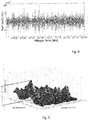
- An example of the track signal z plotted in the wavelength domain is shown in the periodogram of Fig. 5 .
- the vertical profile signal is used to identify track sections that may require maintenance. For example, alarms can be set according to the amplitude of defects within a specific wavelength band.
- an in-service vehicle that is instrumented for monitoring bearing health can additionally be used for monitoring the condition of the track on which the rail vehicle runs.
- the method and system of the invention may be solely dedicated to the identification of surface defects in the track.
Abstract
- a step (100) of obtaining a vertical acceleration signal acc1, by measuring vertical acceleration of a bogie of a rail vehicle that runs on the rail surface;
- a step (200) of processing the vertical acceleration signal acc1 to obtain a vertical velocity signal vel1;
- a step (300) of determining the vertical profile signal of the rail surface, by using the vertical acceleration signal acc1 and the vertical velocity signal vel1 as inputs to a simulation model of the bogie, said model comprising an unsprung mass m1 connected to a sprung mass m2, wherein the vertical acceleration signal acc1 represents the vertical acceleration of the unsprung mass m1; and
- a step (400) of measuring a linear velocity signal n of the rail vehicle, wherein the linear velocity signal is used in the step of determining (300) to convert the vertical profile signal z from the time domain to the distance domain.
Description
- The invention relates to the condition monitoring of railway tracks. More specifically, the invention relates to a method and system for determining a vertical profile of a rail surface using vertical acceleration measurements.
- The rail surface of railway tracks experiences wear due to wheel-rail interactions. Over time, the rail surface may often exhibit defects known as corrugation, which is a form of cyclical wear. Severe corrugation will reduce the service life of rail vehicles that run on the rail, meaning that is important for railway and infrastructure operators to be able to detect such surface defects so that necessary track maintenance can be performed.
- Track recording vehicles are known, which include instruments for measuring many different attributes of a railway track. These are specialized vehicles which can be operated only at infrequent intervals, especially on busy lines. The use of in-service vehicles is much preferable.
- One example of a method for detecting rail-top defects using measurements obtained from sensors that can be mounted to an in-service vehicle is known from
EP 2464555 . The method employs an axle box acceleration signal. A vertical and a longitudinal axle box acceleration signal are measured, whereby the longitudinal acceleration is used to remove a signal part from the vertical acceleration signal that relates to vibrations of the wheel set. - A further example is disclosed in
US 6668239 . The method is carried out using a vehicle that is equipped with a vertical acceleration sensor mounted to the vehicle frame at each side of the bogie. The instrumentation package further includes a linear displacement transducer connected between the frame a wheel bearing at each axle end, for measuring vertical displacements of the wheel relative to the frame. The acceleration signal is digitized and subjected to double integration, to obtain vertical displacements of the frame. The corresponding displacements of the top surface of the rail are calculated from the obtained vertical frame displacements and the measured displacements of the wheel relative to the frame. - There is room for improvement.
- The invention defines a method of determining a vertical profile of a rail surface that can be implemented using only one vertical acceleration sensor per rail, and which achieves a high level of accuracy. The method comprises steps of:
- obtaining a vertical acceleration signal acc1, by measuring vertical acceleration of a bogie of a rail vehicle that runs on the rail surface;
- processing the vertical acceleration signal acc1 to obtain a vertical velocity signal vel1;
- determining the vertical profile signal of the rail surface, by using the vertical acceleration signal acc1 and the vertical velocity signal vel1 as inputs to a simulation model of the bogie, said model comprising an unsprung mass m1 connected to a sprung mass m2, wherein the vertical acceleration signal acc1 represents the vertical acceleration of the unsprung mass m1; and
- measuring a linear velocity signal n of the rail vehicle, wherein the linear velocity signal is used in the step of determining to convert the vertical profile signal z from the time domain to the distance domain.
- Preferably, vertical acceleration is measured at an axle box on the bogie, which supports a wheel that runs on the rail and is thus influenced by undulations or corrugations in the rail surface. The dynamic behaviour of the bogie is simulated using a suitable model of the bogie, such as a quarter-bogie model. It is assumed that the axle box, which forms part of the unsprung mass of the bogie, is connected via a primary suspension to a second mass, which is the sprung mass.
- The corresponding equations of motion are then solved using the known mass parameters, stiffness parameters and damping parameters of the system, the measured acceleration signal acc1 and the vertical velocity signal vel1 that is obtained during the step of processing.
- In one example, the step of processing comprises filtering the vertical acceleration signal acc1 using a Butterworth filter. The filtered signal is then converted to the frequency domain, where a single integration operation is performed. The integrated signal is then converted back to the time domain using an inverse Fast Fourier Transform.
- In the method of the invention, the measured signal is subjected to only one integration operation. In comparison with prior art methods, the processed signal comprises relatively little noise, leading to a more accurate result when the equations of motion are solved.
- Suitably, once the vertical profile signal has been calculated in the time domain, it is transformed into the distance domain using the linear speed signal.
- It then becomes possible to classify surface defects, i.e. corrugations, according to their wavelength. In one example, the vertical signal profile undergoes band-pass analysis in three wavelength bands:
- 1. 30 - 80 mm;
- 2. 80 - 300 mm;
- 3. 300 - 1000 mm.
- Needless to say, the number of wavelength bands and their width can vary depending on national or international regulations.
- The signal may be filtered in each band using e.g. a 3-order Butterworth filter. Suitably, corrugation detection is performed in each wavelength band; for example, by applying a threshold to the RMS amplitude or the peak-to-peak amplitude of the signal.
- In a further example, the method of the invention comprises converting the vertical profile signal from the distance domain to the wavelength domain. Alarm thresholds may then be defined for the signal amplitude in the wavelength domain, for a specific wavelength band, such that an alert is transmitted if the signal amplitude exceeds the threshold.
- Thus, potentially harmful corrugations that require repair or maintenance can be identified. In order to locate the exact position of the defects, the vertical profile signal in the distance domain is calculated with respect to distance from a reference point of known geographic position. This information may be obtained, for example, from GPS or from other position location means.
- The present invention further defines a condition monitoring system for detecting corrugations in a rail surface, the system comprising:
- an accelerometer for measuring vertical acceleration, whereby the accelerometer is mounted to a bogie of a rail vehicle that runs on the rail;
- a speed sensor for measuring a linear speed of the rail vehicle;
- a processor configured to receive a vertical acceleration signal acc1 from the accelerometer and to receive a linear speed signal n from the speed sensor.
- The processor is programmed to implement the step of determining according to the method of the invention, to obtain a vertical profile signal z of the rail surface.
- Suitably, the condition monitoring system further comprises means for position location, so that the vertical profile signal z may be calculated in the distance domain with reference to a fixed reference of known position.
- In one embodiment, the processor is further configured to perform a band-pass analysis of the vertical profile signal, to characterize the signal in terms of different wavelength bands corresponding to different classes of corrugation.
- In a further embodiment, the processor is configured to convert the vertical profile signal z into the wavelength domain and is programmed to transmit an alert if an amplitude of the signal in wavelength domain exceeds a predetermined maximum value that has been set for a specific wavelength band.
- The invention will now be described in more detail, with reference to the accompanying figures.
-
- Fig. 1
- is a schematic representation of a train including a condition monitoring system for bearing units that is suitable for use in the method according to the invention;
- Fig. 2
- is a flowchart of an example of method according to the invention;
- Fig. 3
- depicts a quarter-bogie model that is used in the method according to the invention.
- Fig. 4
- shows an example of a vertical profile signal in the distance domain, obtained using the method of the invention.
- Fig. 5
- shows an example of a vertical profile signal in the wavelength domain, obtained using the method of the invention.
-
Fig. 1 is a schematic representation of a train including a condition monitoring system for bearing units of the train. The system comprises multiple condition monitoring units 10 - one for each wheel of the train - for measuring at least one operating parameter of one bearing unit of a train axle box. In the depicted example, thecondition monitoring units 10 are formed as wireless sensor nodes attached to or embedded into the end plate of a double row roller bearing assembly of the hub (not shown). In other examples, the system for measuring and collecting data may be a wired system. - The measured operating parameters include vibrations, and each
unit 10 is equipped with anaccelerometer 12 that measures acceleration in the vertical direction. Typically, bearing temperature is also measured. In addition, at least one condition monitoring unit is equipped with arotational speed sensor 13. - A
control unit 18 for receiving and processing signals obtained from thecondition monitoring units 10 is provided in a locomotive of the train. The communication between thecontrol unit 18 and thecondition monitoring units 10 is at least partiallywireless using antennae 17a. If necessary, each of the wagons is provided or some of the wagons are provided with aremote network manager 15 serving as a wireless network manager, a power supply manager for theunits 10 and as a wireless network extender. The wireless network can be a single-band 2.4GHz network or a dual band 2.4GHz and 5GhHz network. The skilled person may use other communication frequencies or protocols including different protocols for the backbone and for the communication between extenders and theunits 10 depending on the circumstances. - The
control unit 18 is further equipped with aGPS antenna 17c and with anantenna 17b for a mobile communication interface using e.g. a GSM, GPRS, UMTS, LTE or HSDPA standard. - In the embodiment of
Fig. 1 , thecontrol unit 18 comprises aGPS receiver 19 receiving positioning signals from a system ofsatellites 30 as means for detecting a geographic position. - The train runs on a railway track (not shown). The individual rails may contain surface defects, such as corrugations, that affect the vertical acceleration measured by the
sensors 12. The main purpose of thecondition monitoring units 10 is to gather data on the health of the bearings. Thecontrol unit 18 may be programmed to analyse the measured data in real time, or may be configured to transmit the data to e.g. a server for storage in a database. The recorded and transmitted data is preferably tagged with positional information obtained from theGPS receiver 19. - The data may then be retrieved from the database and analysed remotely by a
computer 50 that is programmed, for example, to identify defective operation of the wheel bearings. In the method of the invention, the gathered data is additionally used for condition monitoring of the rails. Specifically, a vertical profile of the rail surfaces is determined, in order to identify track sections where corrugations have a magnitude that is potentially harmful to the service life of rail vehicles. - The method of the invention is depicted by the flow chart in
Fig. 2 . - In a
first step 100, a vertical acceleration signal acc1 is obtained from at least oneaccelerometer 12. - In a
second step 200, the vertical acceleration signal is processed to obtain a vertical velocity signal v1. - The processing suitably comprises filtering of the signal using e.g. a Butterworth filter in the passband of interest. Typically, a high-pass filter with a cut-off frequency of 10 Hz is used. The filtered signal is converted to the frequency domain and is then integrated to obtain a velocity signal in the frequency domain. An inverse FFT is then applied to obtain the vertical velocity signal v1 in the time domain. Omega Arithmetic is one example of a processing method that may be used to obtain the velocity signal vel1 from the acceleration signal acc1.
- In a
third step 300, the vertical velocity signal vel1 and the vertical acceleration signal acc1 are used as inputs to a simulation model of the bogie on which theaccelerometer 12 is mounted, to obtain a track signal z of vertical undulations. - This will be explained with reference to
Figure 3 , which shows a two-mass model of a bogie. The depicted model is generally known as a quarter-bogie model and is widely used in railway vibrations engineering. The model considers the train as two masses connected by a spring k2 and a damper c2, representing the primary suspension. The upper mass m2 represents a quarter of the mass of a bogie frame and train housing. The lower mass m1 simulates half of an axle mass and is an unsprung mass. In response to undulations in therail surface 80, i.e. the vertical rail profile, the upper and lower masses m2 and m1 undergo vertical displacements y2 and y1 respectively. The displacements are influenced by the wheel-to-rail contact stiffness, which is represented by a spring k1. The function to be obtained is z, the vertical rail profile. - The equations of motion for the quarter-bogie model in the time domain are as follows:


- The
accelerometer 12 measures the vertical acceleration of the unsprung mass m1, meaning that the vertical acceleration signal acc1 is equivalent to ÿ1. The vertical velocity signal vel1 that is obtained from acc1 is therefore equal to ẏ1. Further known parameters are the masses m1 and m2 (kg), the spring coefficient k2 (N/m) and damping coefficient c2 of the primary suspension and the spring coefficient k1 (N/m) of the wheel contact stiffness. - First, equation [1] is solved using the vertical velocity signal vel1.
- Suitably, state variables x1, x2 and x 3 are defined, whereby:
- x1 = y1 (vertical displacement of m1), implying that) ẋ1 = vel1.
- x2 = y2 (vertical displacement of m2).
- x3 ẋ2 , which implies that ẋ 3 = ẏ2 (vertical velocity of m2).
- Equation [1] may therefore be expressed in state-variable form as:


- Using known stiffness and damping matrices, equation [1] can be solved as follows:


- Equation [2] can now be solved for the function z:

- Thus, the vertical acceleration signal acc1 is used directly to solve the equations of motion associated with the model. Furthermore, this signal is subjected to only one integration process, to obtain the vertical velocity signal vel1, which is also used as an input to solving the equations. The calculated vertical profile signal z therefore contains minimal noise and has a high degree of accuracy.
- Returning to
Figure 2 , the method of the invention suitably comprises converting the calculated signal from the time domain to the distance domain. The method comprises afurther step 400 of obtaining a speed signal n of the train. In one example, at least one wheel of the train is equipped with a rotational speed sensor 13 (referFig. 1 ), whereby the measured speed in rpm is converted to a linear speed of the train using the known wheel diameter. - Using the measured speed, distance from a fixed reference point can be calculated. In order to locate the vertical track profile in the "real world", the position of the fixed reference point may be obtained, for example, from the
GPS receiver 19 or from a waypoint that triggers the gathering of vertical acceleration data along a particular route section. Alternatively, the location of objects at known positions along or adjacent to the track, such as points or crossings, may be detected. Dead reckoning methods may also be used, including inertial guidance systems, and measuring distance from known positions - An example of the vertical profile signal z in the distance domain is shown in
Fig. 4 . - Surface defects are usually classified according to their wavelength. In a metro line, for example, very short-pitch corrugations have a wavelength A of 3 - 8 cm; short-pitch corrugations have a wavelength A of 8 - 30 cm; medium-pitch corrugations have a wavelength A of 30 - 100 cm.
- The wavelength of track corrugations and their amplitude can be obtained from the vertical profile signal z. Suitably, the signal is converted to the wavelength domain, to enable defects to be classified according to their wavelength. An example of the track signal z plotted in the wavelength domain is shown in the periodogram of
Fig. 5 . - Once obtained, the vertical profile signal is used to identify track sections that may require maintenance. For example, alarms can be set according to the amplitude of defects within a specific wavelength band.
- Thus, an in-service vehicle that is instrumented for monitoring bearing health can additionally be used for monitoring the condition of the track on which the rail vehicle runs. As will be understood, the method and system of the invention may be solely dedicated to the identification of surface defects in the track.
Claims (8)
- A method of determining a vertical profile signal z of a rail surface, comprising:- a step (100) of obtaining a vertical acceleration signal acc1, by measuring vertical acceleration of a bogie of a rail vehicle that runs on the rail surface;- a step (200) of processing the vertical acceleration signal acc1 to obtain a vertical velocity signal vel1;- a step (300) of determining the vertical profile signal of the rail surface, by using the vertical acceleration signal acc1 and the vertical velocity signal vel1 as inputs to a simulation model of the bogie, said model comprising an unsprung mass m1 connected to a sprung mass m2, wherein the vertical acceleration signal acc1 represents the vertical acceleration of the unsprung mass m1; and- a step (400) of measuring a linear velocity signal n of the rail vehicle, wherein the linear velocity signal is used in the step of determining (300) to convert the vertical profile signal z from the time domain to the distance domain.
- The method of claim 1, further comprising a step of converting the vertical profile signal to the wavelength domain.
- The method of claim 1 or 2, wherein the step of processing (200) comprises:- filtering the vertical acceleration signal acc1;- converting the filtered signal to the frequency domain;- single integration of the converted signal in the frequency domain; and- obtaining the vertical velocity signal vel1 by converting the integrated signal to the time domain.
- The method of any preceding claim, wherein the simulation model of the bogie is a quarter-bogie model.
- A condition monitoring system for detecting corrugations in a rail surface, the system comprising:- an accelerometer (12) for measuring vertical acceleration, whereby the accelerometer is mounted to a bogie of a rail vehicle that runs on the rail;- a speed sensor (13) for measuring a linear speed of the rail vehicle;- a processor (50) configured to receive a vertical acceleration signal acc1 from the accelerometer (12) and to receive a linear speed signal n from the speed sensor;
wherein,
the processor is programmed to implement the step of determining (300) according to the method of claim 1, to obtain a vertical profile signal z of the rail surface (80). - The condition monitoring system of claim 5, further comprising means for position location, so that the vertical profile signal z may be calculated in the distance domain with reference to a fixed reference of known position.
- The condition monitoring system of claim 5 or 6, wherein the processor (50) is configured to perform a band-pass analysis of the vertical profile signal, to characterize the signal in terms of different wavelength bands corresponding to different classes of corrugation.
- The condition monitoring system of claim 7, wherein the processor is configured to convert the vertical profile signal z into the wavelength domain and is programmed to transmit an alert if an amplitude of the signal in wavelength domain exceeds a predetermined maximum value that has been set for a specific wavelength band.
Applications Claiming Priority (1)
| Application Number | Priority Date | Filing Date | Title |
|---|---|---|---|
| EP16380010 | 2016-03-17 |
Publications (2)
| Publication Number | Publication Date |
|---|---|
| EP3219574A1 true EP3219574A1 (en) | 2017-09-20 |
| EP3219574B1 EP3219574B1 (en) | 2018-11-07 |
Family
ID=55661353
Family Applications (1)
| Application Number | Title | Priority Date | Filing Date |
|---|---|---|---|
| EP16205328.4A Active EP3219574B1 (en) | 2016-03-17 | 2016-12-20 | Method and system for determining a vertical profile of a rail surface |
Country Status (3)
| Country | Link |
|---|---|
| US (1) | US10421470B2 (en) |
| EP (1) | EP3219574B1 (en) |
| CN (1) | CN107200040B (en) |
Cited By (4)
| Publication number | Priority date | Publication date | Assignee | Title |
|---|---|---|---|---|
| US20170267263A1 (en) * | 2016-03-17 | 2017-09-21 | Aktiebolaget Skf | Method and system for determining a vertical profile of a rail surface |
| CN109635386A (en) * | 2018-11-27 | 2019-04-16 | 中电建冀交高速公路投资发展有限公司 | A kind of bridge move vehicle Load Identification Methods |
| WO2019081772A1 (en) * | 2017-10-27 | 2019-05-02 | Perpetuum Ltd | Monitoring railway track |
| GB2620615A (en) * | 2022-07-14 | 2024-01-17 | Network Rail Infrastructure Ltd | Prediction of cyclic top events |
Families Citing this family (5)
| Publication number | Priority date | Publication date | Assignee | Title |
|---|---|---|---|---|
| JP6657162B2 (en) * | 2017-10-31 | 2020-03-04 | 三菱重工業株式会社 | Error detection device, error detection method, program |
| CN108828068B (en) * | 2018-01-18 | 2021-05-25 | 武汉汉宁轨道交通技术有限公司 | Track surface wave abrasion and damage detection device and method |
| CN109785301B (en) * | 2018-12-27 | 2020-12-15 | 北京交通大学 | Rail corrugation period evaluation method based on image processing |
| JP7339534B2 (en) | 2019-12-10 | 2023-09-06 | 日本製鉄株式会社 | Processing device, processing method, and program |
| DE102020209184A1 (en) * | 2020-03-12 | 2021-09-16 | Aktiebolaget Skf | System for monitoring a wheel-rail contact force |
Citations (4)
| Publication number | Priority date | Publication date | Assignee | Title |
|---|---|---|---|---|
| CH674180A5 (en) * | 1986-08-01 | 1990-05-15 | Magyar Allamvasutak | |
| WO2000070148A1 (en) * | 1999-05-14 | 2000-11-23 | Aea Technology Plc | Track monitoring equipment |
| WO2006130908A1 (en) * | 2005-06-08 | 2006-12-14 | Qr Limited | Estimation of wheel rail interaction forces |
| EP2464555A1 (en) | 2009-08-13 | 2012-06-20 | Technische Universiteit Delft | Method and instrumentation for detection of rail defects, in particular rail top defects |
Family Cites Families (20)
| Publication number | Priority date | Publication date | Assignee | Title |
|---|---|---|---|---|
| CH630016A5 (en) * | 1979-03-06 | 1982-05-28 | Speno International | Device for measuring the undulating-type deformations of the rolling surface of the rails of a railway |
| US4741207A (en) * | 1986-12-29 | 1988-05-03 | Spangler Elson B | Method and system for measurement of road profile |
| US5065618A (en) * | 1990-11-14 | 1991-11-19 | Hodges Transportation Inc. | Method and apparatus for determining terrain surface profiles |
| US5579013A (en) * | 1994-05-05 | 1996-11-26 | General Electric Company | Mobile tracking unit capable of detecting defective conditions in railway vehicle wheels and railtracks |
| US5924654A (en) * | 1997-10-06 | 1999-07-20 | Zeftek, Inc. | Railroad car sensing system |
| US6416020B1 (en) * | 1998-07-10 | 2002-07-09 | Leif Gronskov | Method and apparatus for detecting defective track wheels |
| WO2000060322A1 (en) * | 1999-04-01 | 2000-10-12 | Siemens Schweiz Ag | Method and device for monitoring the chassis of multiple-axle vehicles |
| DE102004012770B4 (en) * | 2004-03-15 | 2006-04-20 | Ab Skf | Device for attaching to a wheel and wheel with the device |
| KR20070069629A (en) * | 2005-12-28 | 2007-07-03 | 한국철도기술연구원 | Apparatus for measuring a railroad track parameter |
| JP2011214933A (en) * | 2010-03-31 | 2011-10-27 | Kawasaki Heavy Ind Ltd | Distance-image acquisition system for track |
| CN102252636B (en) * | 2011-04-12 | 2012-09-05 | 中国航空工业第六一八研究所 | Multi-wavelength detection device and detection method for smoothness of high-speed railway track |
| CN102797202B (en) * | 2012-08-29 | 2014-12-10 | 北京交通大学 | Transverse track irregularity detecting method based on observer |
| JP5959378B2 (en) * | 2012-09-11 | 2016-08-02 | 川崎重工業株式会社 | Load measuring method and apparatus, railway vehicle equipped with load measuring apparatus, and load management system |
| AU2014272135B2 (en) * | 2013-05-30 | 2020-01-16 | Wabtec Holding Corp. | Broken rail detection system for communications-based train control |
| US9469198B2 (en) * | 2013-09-18 | 2016-10-18 | General Electric Company | System and method for identifying damaged sections of a route |
| CN104032629B (en) * | 2014-06-10 | 2016-03-02 | 南京理工大学 | A kind of vertical track long wave irregularity on-line monitoring method and system |
| US9701326B2 (en) * | 2014-09-12 | 2017-07-11 | Westinghouse Air Brake Technologies Corporation | Broken rail detection system for railway systems |
| CN104563083B (en) * | 2015-01-15 | 2016-07-20 | 中铁第四勘察设计院集团有限公司 | Impact elasticity ripple detection ballastless track of high-speed railway base comes to nothing the structure of state and method |
| CN104878668A (en) * | 2015-05-29 | 2015-09-02 | 南京理工大学 | Rail vertical irregularity estimation method and system based on extended Kalman filtering |
| EP3219574B1 (en) * | 2016-03-17 | 2018-11-07 | Aktiebolaget SKF | Method and system for determining a vertical profile of a rail surface |
-
2016
- 2016-12-20 EP EP16205328.4A patent/EP3219574B1/en active Active
-
2017
- 2017-02-06 CN CN201710066102.7A patent/CN107200040B/en active Active
- 2017-03-06 US US15/450,794 patent/US10421470B2/en active Active
Patent Citations (5)
| Publication number | Priority date | Publication date | Assignee | Title |
|---|---|---|---|---|
| CH674180A5 (en) * | 1986-08-01 | 1990-05-15 | Magyar Allamvasutak | |
| WO2000070148A1 (en) * | 1999-05-14 | 2000-11-23 | Aea Technology Plc | Track monitoring equipment |
| US6668239B1 (en) | 1999-05-14 | 2003-12-23 | Aea Technology Plc | Track monitoring equipment |
| WO2006130908A1 (en) * | 2005-06-08 | 2006-12-14 | Qr Limited | Estimation of wheel rail interaction forces |
| EP2464555A1 (en) | 2009-08-13 | 2012-06-20 | Technische Universiteit Delft | Method and instrumentation for detection of rail defects, in particular rail top defects |
Non-Patent Citations (1)
| Title |
|---|
| WEI XIUKUN ET AL: "Urban rail track condition monitoring based on in-service vehicle acceleration measurements", MEASUREMENT, vol. 80, 27 November 2015 (2015-11-27), pages 217 - 228, XP029358654, ISSN: 0263-2241, DOI: 10.1016/J.MEASUREMENT.2015.11.033 * |
Cited By (7)
| Publication number | Priority date | Publication date | Assignee | Title |
|---|---|---|---|---|
| US20170267263A1 (en) * | 2016-03-17 | 2017-09-21 | Aktiebolaget Skf | Method and system for determining a vertical profile of a rail surface |
| US10421470B2 (en) * | 2016-03-17 | 2019-09-24 | Aktiebolaget Skf | Method and system for determining a vertical profile of a rail surface |
| WO2019081772A1 (en) * | 2017-10-27 | 2019-05-02 | Perpetuum Ltd | Monitoring railway track |
| CN109635386A (en) * | 2018-11-27 | 2019-04-16 | 中电建冀交高速公路投资发展有限公司 | A kind of bridge move vehicle Load Identification Methods |
| CN109635386B (en) * | 2018-11-27 | 2022-10-04 | 中电建冀交高速公路投资发展有限公司 | Bridge moving vehicle load identification method |
| GB2620615A (en) * | 2022-07-14 | 2024-01-17 | Network Rail Infrastructure Ltd | Prediction of cyclic top events |
| WO2024013470A1 (en) * | 2022-07-14 | 2024-01-18 | Network Rail Infrastructure Limited | Prediction of cyclic top events |
Also Published As
| Publication number | Publication date |
|---|---|
| CN107200040B (en) | 2022-10-28 |
| US10421470B2 (en) | 2019-09-24 |
| EP3219574B1 (en) | 2018-11-07 |
| US20170267263A1 (en) | 2017-09-21 |
| CN107200040A (en) | 2017-09-26 |
Similar Documents
| Publication | Publication Date | Title |
|---|---|---|
| EP3219574B1 (en) | Method and system for determining a vertical profile of a rail surface | |
| CN104364629B (en) | The track component inspection analyzed based on resonance signal | |
| JP4298433B2 (en) | Railway vehicle abnormality detection device | |
| Mori et al. | Condition monitoring of railway track using in-service vehicle | |
| Molodova et al. | Automatic detection of squats in railway infrastructure | |
| JP5382991B2 (en) | Abnormality diagnosis method and abnormality diagnosis system for track system | |
| CN106018557B (en) | A kind of raceway surface recess detection method based on wavelet analysis | |
| CN112543725A (en) | Railcar acoustic monitoring system and method of use thereof | |
| JP2007256153A (en) | System for detecting railway vehicle truck abnormality | |
| JP2012208043A (en) | Method and device for identifying vibration characteristic of railroad structure | |
| JP2021501097A (en) | Axle monitoring of railroad vehicles | |
| CN106379376A (en) | on-line rail state monitoring method based on vibration and positioning monitoring | |
| CN104713769B (en) | Active shock excitation detection system for road condition assessment | |
| JP4388594B2 (en) | Railway vehicle abnormality detection device | |
| Tsunashima et al. | Condition monitoring of railway tracks using compact size on-board monitoring device | |
| Lingamanaik et al. | Using instrumented revenue vehicles to inspect track integrity and rolling stock performance in a passenger network during peak times | |
| CN106052606B (en) | A kind of raceway surface recess detection method for the Wavelet Energy Spectrum that is averaged based on scale | |
| CN110171442B (en) | Detection system and detection method for wheel flat scars | |
| CN116252820A (en) | Polygonal quantitative detection method for high-speed train wheels driven by improved frequency domain integration method | |
| KR102305601B1 (en) | Hanging sleeper monitoring system and method | |
| Entezami et al. | Lineside and on-board monitoring techniques for infrastructure and rolling stock on high-speed lines | |
| CN115372042A (en) | Method and system for detecting working performance of bridge expansion joint based on smart phone | |
| JP2023025778A (en) | Abnormality monitoring method of bridge girder bearing portion and abnormality monitoring system of bridge girder bearing portion | |
| CN114239347A (en) | Efficient method for measuring railway track supporting rigidity in real time based on vibration signals of operation train | |
| JP2005306119A (en) | Riding comfort monitoring system |
Legal Events
| Date | Code | Title | Description |
|---|---|---|---|
| PUAI | Public reference made under article 153(3) epc to a published international application that has entered the european phase |
Free format text: ORIGINAL CODE: 0009012 |
|
| AK | Designated contracting states |
Kind code of ref document: A1 Designated state(s): AL AT BE BG CH CY CZ DE DK EE ES FI FR GB GR HR HU IE IS IT LI LT LU LV MC MK MT NL NO PL PT RO RS SE SI SK SM TR |
|
| AX | Request for extension of the european patent |
Extension state: BA ME |
|
| 17P | Request for examination filed |
Effective date: 20171220 |
|
| RBV | Designated contracting states (corrected) |
Designated state(s): AL AT BE BG CH CY CZ DE DK EE ES FI FR GB GR HR HU IE IS IT LI LT LU LV MC MK MT NL NO PL PT RO RS SE SI SK SM TR |
|
| GRAP | Despatch of communication of intention to grant a patent |
Free format text: ORIGINAL CODE: EPIDOSNIGR1 |
|
| INTG | Intention to grant announced |
Effective date: 20180517 |
|
| GRAS | Grant fee paid |
Free format text: ORIGINAL CODE: EPIDOSNIGR3 |
|
| GRAA | (expected) grant |
Free format text: ORIGINAL CODE: 0009210 |
|
| AK | Designated contracting states |
Kind code of ref document: B1 Designated state(s): AL AT BE BG CH CY CZ DE DK EE ES FI FR GB GR HR HU IE IS IT LI LT LU LV MC MK MT NL NO PL PT RO RS SE SI SK SM TR |
|
| REG | Reference to a national code |
Ref country code: GB Ref legal event code: FG4D |
|
| REG | Reference to a national code |
Ref country code: CH Ref legal event code: EP Ref country code: AT Ref legal event code: REF Ref document number: 1061711 Country of ref document: AT Kind code of ref document: T Effective date: 20181115 |
|
| REG | Reference to a national code |
Ref country code: DE Ref legal event code: R096 Ref document number: 602016006981 Country of ref document: DE |
|
| REG | Reference to a national code |
Ref country code: IE Ref legal event code: FG4D |
|
| REG | Reference to a national code |
Ref country code: NL Ref legal event code: MP Effective date: 20181107 |
|
| REG | Reference to a national code |
Ref country code: LT Ref legal event code: MG4D |
|
| REG | Reference to a national code |
Ref country code: AT Ref legal event code: MK05 Ref document number: 1061711 Country of ref document: AT Kind code of ref document: T Effective date: 20181107 |
|
| PG25 | Lapsed in a contracting state [announced via postgrant information from national office to epo] |
Ref country code: LV Free format text: LAPSE BECAUSE OF FAILURE TO SUBMIT A TRANSLATION OF THE DESCRIPTION OR TO PAY THE FEE WITHIN THE PRESCRIBED TIME-LIMIT Effective date: 20181107 Ref country code: AT Free format text: LAPSE BECAUSE OF FAILURE TO SUBMIT A TRANSLATION OF THE DESCRIPTION OR TO PAY THE FEE WITHIN THE PRESCRIBED TIME-LIMIT Effective date: 20181107 Ref country code: FI Free format text: LAPSE BECAUSE OF FAILURE TO SUBMIT A TRANSLATION OF THE DESCRIPTION OR TO PAY THE FEE WITHIN THE PRESCRIBED TIME-LIMIT Effective date: 20181107 Ref country code: NO Free format text: LAPSE BECAUSE OF FAILURE TO SUBMIT A TRANSLATION OF THE DESCRIPTION OR TO PAY THE FEE WITHIN THE PRESCRIBED TIME-LIMIT Effective date: 20190207 Ref country code: BG Free format text: LAPSE BECAUSE OF FAILURE TO SUBMIT A TRANSLATION OF THE DESCRIPTION OR TO PAY THE FEE WITHIN THE PRESCRIBED TIME-LIMIT Effective date: 20190207 Ref country code: HR Free format text: LAPSE BECAUSE OF FAILURE TO SUBMIT A TRANSLATION OF THE DESCRIPTION OR TO PAY THE FEE WITHIN THE PRESCRIBED TIME-LIMIT Effective date: 20181107 Ref country code: IS Free format text: LAPSE BECAUSE OF FAILURE TO SUBMIT A TRANSLATION OF THE DESCRIPTION OR TO PAY THE FEE WITHIN THE PRESCRIBED TIME-LIMIT Effective date: 20190307 Ref country code: ES Free format text: LAPSE BECAUSE OF FAILURE TO SUBMIT A TRANSLATION OF THE DESCRIPTION OR TO PAY THE FEE WITHIN THE PRESCRIBED TIME-LIMIT Effective date: 20181107 Ref country code: LT Free format text: LAPSE BECAUSE OF FAILURE TO SUBMIT A TRANSLATION OF THE DESCRIPTION OR TO PAY THE FEE WITHIN THE PRESCRIBED TIME-LIMIT Effective date: 20181107 |
|
| PG25 | Lapsed in a contracting state [announced via postgrant information from national office to epo] |
Ref country code: SE Free format text: LAPSE BECAUSE OF FAILURE TO SUBMIT A TRANSLATION OF THE DESCRIPTION OR TO PAY THE FEE WITHIN THE PRESCRIBED TIME-LIMIT Effective date: 20181107 Ref country code: GR Free format text: LAPSE BECAUSE OF FAILURE TO SUBMIT A TRANSLATION OF THE DESCRIPTION OR TO PAY THE FEE WITHIN THE PRESCRIBED TIME-LIMIT Effective date: 20190208 Ref country code: PT Free format text: LAPSE BECAUSE OF FAILURE TO SUBMIT A TRANSLATION OF THE DESCRIPTION OR TO PAY THE FEE WITHIN THE PRESCRIBED TIME-LIMIT Effective date: 20190307 Ref country code: NL Free format text: LAPSE BECAUSE OF FAILURE TO SUBMIT A TRANSLATION OF THE DESCRIPTION OR TO PAY THE FEE WITHIN THE PRESCRIBED TIME-LIMIT Effective date: 20181107 Ref country code: AL Free format text: LAPSE BECAUSE OF FAILURE TO SUBMIT A TRANSLATION OF THE DESCRIPTION OR TO PAY THE FEE WITHIN THE PRESCRIBED TIME-LIMIT Effective date: 20181107 Ref country code: RS Free format text: LAPSE BECAUSE OF FAILURE TO SUBMIT A TRANSLATION OF THE DESCRIPTION OR TO PAY THE FEE WITHIN THE PRESCRIBED TIME-LIMIT Effective date: 20181107 |
|
| PG25 | Lapsed in a contracting state [announced via postgrant information from national office to epo] |
Ref country code: CZ Free format text: LAPSE BECAUSE OF FAILURE TO SUBMIT A TRANSLATION OF THE DESCRIPTION OR TO PAY THE FEE WITHIN THE PRESCRIBED TIME-LIMIT Effective date: 20181107 Ref country code: PL Free format text: LAPSE BECAUSE OF FAILURE TO SUBMIT A TRANSLATION OF THE DESCRIPTION OR TO PAY THE FEE WITHIN THE PRESCRIBED TIME-LIMIT Effective date: 20181107 Ref country code: IT Free format text: LAPSE BECAUSE OF FAILURE TO SUBMIT A TRANSLATION OF THE DESCRIPTION OR TO PAY THE FEE WITHIN THE PRESCRIBED TIME-LIMIT Effective date: 20181107 Ref country code: DK Free format text: LAPSE BECAUSE OF FAILURE TO SUBMIT A TRANSLATION OF THE DESCRIPTION OR TO PAY THE FEE WITHIN THE PRESCRIBED TIME-LIMIT Effective date: 20181107 |
|
| REG | Reference to a national code |
Ref country code: DE Ref legal event code: R097 Ref document number: 602016006981 Country of ref document: DE |
|
| PG25 | Lapsed in a contracting state [announced via postgrant information from national office to epo] |
Ref country code: SM Free format text: LAPSE BECAUSE OF FAILURE TO SUBMIT A TRANSLATION OF THE DESCRIPTION OR TO PAY THE FEE WITHIN THE PRESCRIBED TIME-LIMIT Effective date: 20181107 Ref country code: LU Free format text: LAPSE BECAUSE OF NON-PAYMENT OF DUE FEES Effective date: 20181220 Ref country code: RO Free format text: LAPSE BECAUSE OF FAILURE TO SUBMIT A TRANSLATION OF THE DESCRIPTION OR TO PAY THE FEE WITHIN THE PRESCRIBED TIME-LIMIT Effective date: 20181107 Ref country code: SK Free format text: LAPSE BECAUSE OF FAILURE TO SUBMIT A TRANSLATION OF THE DESCRIPTION OR TO PAY THE FEE WITHIN THE PRESCRIBED TIME-LIMIT Effective date: 20181107 Ref country code: EE Free format text: LAPSE BECAUSE OF FAILURE TO SUBMIT A TRANSLATION OF THE DESCRIPTION OR TO PAY THE FEE WITHIN THE PRESCRIBED TIME-LIMIT Effective date: 20181107 Ref country code: MC Free format text: LAPSE BECAUSE OF FAILURE TO SUBMIT A TRANSLATION OF THE DESCRIPTION OR TO PAY THE FEE WITHIN THE PRESCRIBED TIME-LIMIT Effective date: 20181107 |
|
| PLBE | No opposition filed within time limit |
Free format text: ORIGINAL CODE: 0009261 |
|
| STAA | Information on the status of an ep patent application or granted ep patent |
Free format text: STATUS: NO OPPOSITION FILED WITHIN TIME LIMIT |
|
| REG | Reference to a national code |
Ref country code: IE Ref legal event code: MM4A |
|
| REG | Reference to a national code |
Ref country code: BE Ref legal event code: MM Effective date: 20181231 |
|
| 26N | No opposition filed |
Effective date: 20190808 |
|
| PG25 | Lapsed in a contracting state [announced via postgrant information from national office to epo] |
Ref country code: SI Free format text: LAPSE BECAUSE OF FAILURE TO SUBMIT A TRANSLATION OF THE DESCRIPTION OR TO PAY THE FEE WITHIN THE PRESCRIBED TIME-LIMIT Effective date: 20181107 Ref country code: IE Free format text: LAPSE BECAUSE OF NON-PAYMENT OF DUE FEES Effective date: 20181220 |
|
| PG25 | Lapsed in a contracting state [announced via postgrant information from national office to epo] |
Ref country code: BE Free format text: LAPSE BECAUSE OF NON-PAYMENT OF DUE FEES Effective date: 20181231 |
|
| PG25 | Lapsed in a contracting state [announced via postgrant information from national office to epo] |
Ref country code: MT Free format text: LAPSE BECAUSE OF NON-PAYMENT OF DUE FEES Effective date: 20181220 |
|
| PG25 | Lapsed in a contracting state [announced via postgrant information from national office to epo] |
Ref country code: TR Free format text: LAPSE BECAUSE OF FAILURE TO SUBMIT A TRANSLATION OF THE DESCRIPTION OR TO PAY THE FEE WITHIN THE PRESCRIBED TIME-LIMIT Effective date: 20181107 |
|
| PG25 | Lapsed in a contracting state [announced via postgrant information from national office to epo] |
Ref country code: MK Free format text: LAPSE BECAUSE OF NON-PAYMENT OF DUE FEES Effective date: 20181107 Ref country code: HU Free format text: LAPSE BECAUSE OF FAILURE TO SUBMIT A TRANSLATION OF THE DESCRIPTION OR TO PAY THE FEE WITHIN THE PRESCRIBED TIME-LIMIT; INVALID AB INITIO Effective date: 20161220 Ref country code: CY Free format text: LAPSE BECAUSE OF FAILURE TO SUBMIT A TRANSLATION OF THE DESCRIPTION OR TO PAY THE FEE WITHIN THE PRESCRIBED TIME-LIMIT Effective date: 20181107 |
|
| REG | Reference to a national code |
Ref country code: CH Ref legal event code: PL |
|
| PG25 | Lapsed in a contracting state [announced via postgrant information from national office to epo] |
Ref country code: CH Free format text: LAPSE BECAUSE OF NON-PAYMENT OF DUE FEES Effective date: 20191231 Ref country code: LI Free format text: LAPSE BECAUSE OF NON-PAYMENT OF DUE FEES Effective date: 20191231 |
|
| GBPC | Gb: european patent ceased through non-payment of renewal fee |
Effective date: 20201220 |
|
| PG25 | Lapsed in a contracting state [announced via postgrant information from national office to epo] |
Ref country code: GB Free format text: LAPSE BECAUSE OF NON-PAYMENT OF DUE FEES Effective date: 20201220 |
|
| PGFP | Annual fee paid to national office [announced via postgrant information from national office to epo] |
Ref country code: DE Payment date: 20221227 Year of fee payment: 7 |
|
| P01 | Opt-out of the competence of the unified patent court (upc) registered |
Effective date: 20230513 |
|
| PGFP | Annual fee paid to national office [announced via postgrant information from national office to epo] |
Ref country code: FR Payment date: 20231226 Year of fee payment: 8 |