EP3219408A1 - Continuous casting method for steel - Google Patents
Continuous casting method for steel Download PDFInfo
- Publication number
- EP3219408A1 EP3219408A1 EP14908904.7A EP14908904A EP3219408A1 EP 3219408 A1 EP3219408 A1 EP 3219408A1 EP 14908904 A EP14908904 A EP 14908904A EP 3219408 A1 EP3219408 A1 EP 3219408A1
- Authority
- EP
- European Patent Office
- Prior art keywords
- strand
- thickness
- denotes
- width
- pressing
- Prior art date
- Legal status (The legal status is an assumption and is not a legal conclusion. Google has not performed a legal analysis and makes no representation as to the accuracy of the status listed.)
- Granted
Links
Images

Classifications
-
- B—PERFORMING OPERATIONS; TRANSPORTING
- B22—CASTING; POWDER METALLURGY
- B22D—CASTING OF METALS; CASTING OF OTHER SUBSTANCES BY THE SAME PROCESSES OR DEVICES
- B22D11/00—Continuous casting of metals, i.e. casting in indefinite lengths
- B22D11/04—Continuous casting of metals, i.e. casting in indefinite lengths into open-ended moulds
-
- B—PERFORMING OPERATIONS; TRANSPORTING
- B22—CASTING; POWDER METALLURGY
- B22D—CASTING OF METALS; CASTING OF OTHER SUBSTANCES BY THE SAME PROCESSES OR DEVICES
- B22D11/00—Continuous casting of metals, i.e. casting in indefinite lengths
- B22D11/16—Controlling or regulating processes or operations
- B22D11/20—Controlling or regulating processes or operations for removing cast stock
- B22D11/207—Controlling or regulating processes or operations for removing cast stock responsive to thickness of solidified shell
-
- B—PERFORMING OPERATIONS; TRANSPORTING
- B22—CASTING; POWDER METALLURGY
- B22D—CASTING OF METALS; CASTING OF OTHER SUBSTANCES BY THE SAME PROCESSES OR DEVICES
- B22D11/00—Continuous casting of metals, i.e. casting in indefinite lengths
- B22D11/16—Controlling or regulating processes or operations
- B22D11/20—Controlling or regulating processes or operations for removing cast stock
-
- B—PERFORMING OPERATIONS; TRANSPORTING
- B21—MECHANICAL METAL-WORKING WITHOUT ESSENTIALLY REMOVING MATERIAL; PUNCHING METAL
- B21B—ROLLING OF METAL
- B21B1/00—Metal-rolling methods or mills for making semi-finished products of solid or profiled cross-section; Sequence of operations in milling trains; Layout of rolling-mill plant, e.g. grouping of stands; Succession of passes or of sectional pass alternations
- B21B1/46—Metal-rolling methods or mills for making semi-finished products of solid or profiled cross-section; Sequence of operations in milling trains; Layout of rolling-mill plant, e.g. grouping of stands; Succession of passes or of sectional pass alternations for rolling metal immediately subsequent to continuous casting
- B21B1/463—Metal-rolling methods or mills for making semi-finished products of solid or profiled cross-section; Sequence of operations in milling trains; Layout of rolling-mill plant, e.g. grouping of stands; Succession of passes or of sectional pass alternations for rolling metal immediately subsequent to continuous casting in a continuous process, i.e. the cast not being cut before rolling
-
- B—PERFORMING OPERATIONS; TRANSPORTING
- B22—CASTING; POWDER METALLURGY
- B22D—CASTING OF METALS; CASTING OF OTHER SUBSTANCES BY THE SAME PROCESSES OR DEVICES
- B22D11/00—Continuous casting of metals, i.e. casting in indefinite lengths
- B22D11/04—Continuous casting of metals, i.e. casting in indefinite lengths into open-ended moulds
- B22D11/041—Continuous casting of metals, i.e. casting in indefinite lengths into open-ended moulds for vertical casting
-
- B—PERFORMING OPERATIONS; TRANSPORTING
- B22—CASTING; POWDER METALLURGY
- B22D—CASTING OF METALS; CASTING OF OTHER SUBSTANCES BY THE SAME PROCESSES OR DEVICES
- B22D11/00—Continuous casting of metals, i.e. casting in indefinite lengths
- B22D11/12—Accessories for subsequent treating or working cast stock in situ
- B22D11/1206—Accessories for subsequent treating or working cast stock in situ for plastic shaping of strands
-
- B—PERFORMING OPERATIONS; TRANSPORTING
- B22—CASTING; POWDER METALLURGY
- B22D—CASTING OF METALS; CASTING OF OTHER SUBSTANCES BY THE SAME PROCESSES OR DEVICES
- B22D11/00—Continuous casting of metals, i.e. casting in indefinite lengths
- B22D11/12—Accessories for subsequent treating or working cast stock in situ
- B22D11/128—Accessories for subsequent treating or working cast stock in situ for removing
-
- B—PERFORMING OPERATIONS; TRANSPORTING
- B22—CASTING; POWDER METALLURGY
- B22D—CASTING OF METALS; CASTING OF OTHER SUBSTANCES BY THE SAME PROCESSES OR DEVICES
- B22D11/00—Continuous casting of metals, i.e. casting in indefinite lengths
- B22D11/12—Accessories for subsequent treating or working cast stock in situ
- B22D11/128—Accessories for subsequent treating or working cast stock in situ for removing
- B22D11/1282—Vertical casting and curving the cast stock to the horizontal
-
- B—PERFORMING OPERATIONS; TRANSPORTING
- B22—CASTING; POWDER METALLURGY
- B22D—CASTING OF METALS; CASTING OF OTHER SUBSTANCES BY THE SAME PROCESSES OR DEVICES
- B22D11/00—Continuous casting of metals, i.e. casting in indefinite lengths
- B22D11/12—Accessories for subsequent treating or working cast stock in situ
- B22D11/128—Accessories for subsequent treating or working cast stock in situ for removing
- B22D11/1287—Rolls; Lubricating, cooling or heating rolls while in use
-
- B—PERFORMING OPERATIONS; TRANSPORTING
- B21—MECHANICAL METAL-WORKING WITHOUT ESSENTIALLY REMOVING MATERIAL; PUNCHING METAL
- B21B—ROLLING OF METAL
- B21B2201/00—Special rolling modes
- B21B2201/14—Soft reduction
Definitions
- the present invention relates to a continuous steel casting method that prevents component segregation that occurs at a thickness-wise middle portion of a continuously cast strand, that is, center segregation.
- unsolidified layer unsolidified part of molten steel
- solidification shrinkage whereby the unsolidified part of the molten steel flows in the direction of withdrawal of the strand.
- solute elements such as carbon (C), phosphorus (P), sulfur (S), and manganese (Mn) are concentrated.
- C carbon
- P phosphorus
- S sulfur
- Mn manganese
- center segregation occurs.
- the causes of the flow of the concentrated molten steel at the end of the solidification include, besides the above-described solidification shrinkage, bulging of the strand between rolls due to molten steel static pressure and misalignment of strand support rolls.
- This center segregation impairs the quality of steel products, particularly, thick steel plates.
- a line pipe material for oil transportation or natural gas transportation has center segregation, the action of sour gas causes hydrogen induced cracking from the center segregation.
- Similar problems can occur also in structures including offshore structures, storage tank, and oil tanks.
- steel has been frequently required to be used under severe conditions such as under a low temperature or under a highly corrosive environment, whereby reduction of center segregation in the strand has been becoming increasingly important.
- the "solidification-terminal stage soft reduction method” is a method in which multiple pressing rolls are arranged at or around the solidification completion position of the strand and a continuously cast strand is gradually pressed down by the pressing rolls at a pressing speed approximately corresponding to the rate of solidification shrinkage so as to prevent occurrence of voids or flows of concentrated molten steel in the center portion of the strand, whereby the center segregation of the strand is suppressed.
- Patent Literature 1 describes a continuous casting method that includes subjecting soft reduction to a terminal solidification portion of a continuously cast strand and in which the rate at which the strand is pressed per unit time in a section in which the strand is subjected to soft reduction is determined by the strand surface temperature at the pressing start time and the thickness of the unsolidified layer of the strand at the press position.
- Patent Literature 2 and Patent Literature 3 each describe a continuous casting continuous steel casting method while pressing a strand with multiple pairs of rolls within a region from the time point at which a thickness-wise middle portion of the bloom strand has a temperature corresponding to the solid fraction of 0.1 to 0.3 to the time point at which the thickness-wise middle portion has a temperature corresponding to the flow-limit solid fraction.
- the speed at which the strand is pressed is further increased toward the downstream side in the casting direction with increasing solid fraction at the strand thickness-wise middle portion.
- Patent Literature 4 describes a continuous steel casting method with an application of pressing force to the strand that is being cast.
- the pressing conditions are determined or adjusted on the basis of the information of the shape of a cross section of the strand taken perpendicular to the longitudinal direction of the strand and the information of the shape of an unsolidified portion in the cross section.
- the inventors have found the following facts from experience.
- the time at which the soft reduction is to be started and the time at which the soft reduction is to be finished do not change regardless of the thickness of the strand, whereas the optimum pressing speed in the range in which the pressing force is applied to the strand (referred to as "soft reduction zone”) changes in accordance with the thickness of the strand.
- the thickness of the slab strand is determined by the thickness of the rolled steel product and the pressing ratio during rolling required for the specifications of the steel product (strand thickness/steel product thickness).
- the thickness of the strand is determined in accordance with the specifications. If a strand having the determined thickness has never been cast before with the solidification-terminal stage soft reduction method, there is a need for additionally determining an optimum pressing speed during the soft reduction for the strand thickness. Every time when the optimum pressing speed is to be determined, an optimum reduction rate in the soft reduction zone is determined through casting experiments using an actual machine under the settings of various different levels of reduction rate, which requires significant time and cost. Specifically, the achievement of a method for simply obtaining an optimum reduction rate in the soft reduction zone in accordance with the thickness of the slab strand has been a challenge.
- the “reduction rate” refers to the state of the degree of a roll opening determined in such a manner that the distance between opposing rolls (referred to as “the roll gap”) gradually decreases toward the downstream side in the casting direction.
- the reduction rate is usually expressed by the amount by which the degree of the roll opening decreases per 1 m (mm/m).
- the value obtained by multiplying the reduction rate (mm/m) by the strand withdrawal speed (m/min) is calculated as the pressing speed (mm/min).
- the inventors have verified the usefulness of the above-described cited documents from the standpoint of the above-described problem that the inventors are trying to solve.
- Patent Literature 1 focuses an attention on the unsolidified layer thickness of the strand as an indicator for effectively performing soft reduction. According to Patent Literature 1, this is based on the finding that the pressing rate determined for the pressing rolls is transmitted in a smaller rate to the interface of solid and liquid phases of the strand (hereinafter the rate is referred to as "pressing efficiency") on the casting downstream side, that is, with decreasing unsolidified layer thickness of the strand.
- the rate is referred to as "pressing efficiency”
- the center segregation becomes apparent in a center region of the strand having an unsolidified layer thickness of approximately 10 mm or smaller. According to the relationship between the unsolidified layer thickness D and the pressing speed required per unit time shown in Fig.
- Patent Literature 1 the difference between a pressing speed required for the unsolidified layer thickness of 10 mm and a pressing speed required for the unsolidified layer thickness of 0 mm is approximately 10% at most.
- Example 10 in Patent Literature 1 has described only the test results for one strand thickness (250 mm). Thus, whether the optimum pressing conditions described in Patent Literature 1 are also effective for different strand thicknesses remains in question.
- the sizes of the strands used in the test in thickness and width range between three types of 300 mm ⁇ 500 mm, 162 mm ⁇ 162 mm, and 380 mm ⁇ 560 mm. All the strands having the above sizes relate to the soft-reduction casting of a bloom strand. Since a bloom strand has a ratio between the width and the thickness of the cross section taken perpendicular to the withdrawal direction of the strand (width/thickness) smaller than that of a slab strand, the pressing efficiency in the soft reduction at the end of the solidification of a bloom strand is smaller than that in the case of a slab strand. Accordingly, the pressing rate increases further toward the end of the solidification. The pressing rate is approximately two to three times as large as that in the case of the slab strand in Patent Literature 1. These pressing conditions cannot be directly used in the soft reduction of the slab strand.
- Patent Literature 1 to Patent Literature 3 the reduction rate in the soft reduction zone is varied in the casting withdrawal direction and thus the roll gap of strand support rolls is determined with complexity, entailing complexity of the equipment structure for practice with an actual machine.
- Patent Literature 4 is directed toward a bloom strand.
- the soft reduction conditions are determined on the basis of information of the shape of the cross section taken perpendicular to the longitudinal direction of the strand, that is, the width and the thickness of the strand.
- the soft reduction conditions are determined using the ratio between the width and the thickness of the strand as references and on the basis of the amount of change between the references and the ratio between the width and the thickness of the unsolidified portion of the strand.
- the soft reduction conditions are not determined by directly using the thickness of the strand.
- an unsolidified layer of the strand can have a flat shape either in the lateral direction or in the vertical direction depending on the cooling ratio between the upper and lower surfaces of the strand inside the continuous casting machine or the cooling ratio between the left and right surfaces of the strand inside the continuous casting machine.
- the conditions in Patent Literature 4 are determined in the above-described manner for the purposes of enabling an optimum soft reduction in either of these cases.
- a slab strand toward which the inventors are directed has a far larger long side than a short side and the direction in which the unsolidified layer extends flat does not change; the unsolidified layer is always flat in the lateral direction of the strand.
- Patent Literature 4 is less useful against the problems of the inventors.
- Patent Literature 1 to Patent Literature 4 leads to solutions for the problems of the inventors, and thus development of a new way is required.
- the present invention has been made in view of the above-described circumstances and aims to provide a continuous steel casting method with which soft reduction conditions can be determined in accordance with the thickness of a strand, thereby preventing an occurrence of center segregation in the strand due to an insufficient pressing rate or an occurrence of internal cracks in the strand due to an excessively high pressing rate.
- the pressing conditions are so determined that the thickness of the cast target strand, the reduction rate in a soft reduction zone, and the withdrawal speed of the strand fall within ranges that satisfy the relationship of the expression (1) and the expression (2) in order to reduce center segregation in the slab strand when the strand is continuously cast while the strand is applied with pressing force at the pressing rate approximately corresponding to the rate of solidification shrinkage in the soft reduction zone.
- Fig. 1 is a schematic diagram of a continuous slab casting machine used for embodying the present invention, viewed from the side.
- the continuous slab casting machine 1 includes a mold 5 for receiving and solidifying molten steel 9 and for forming an outer shell shape of a strand 10.
- a tundish 2 is disposed at an appropriate position above the mold 5 to transmit the molten steel 9 provided from a ladle (not illustrated) to the mold 5.
- a sliding nozzle 3 is disposed at the bottom portion of the tundish 2 to adjust the flow rate of the molten steel 9.
- An immersion nozzle 4 is disposed at the lower surface of the sliding nozzle 3.
- multiple pairs of strand support rolls 6 including support rolls, guide rolls, and pinch rolls are disposed.
- spray nozzles such as a water spray nozzle or an air mist spray nozzle (not illustrated) are disposed in gaps between strand support rolls 6 adjacent in the casting direction.
- the strand 10 is cooled by the cooling water (also referred to as "secondary cooling water") sprayed from the spray nozzles in the secondary cooling zone while being withdrawn.
- secondary cooling water also referred to as "secondary cooling water”
- transport rolls 7 are disposed to transport the cast strand 10.
- a strand cutter 8 is disposed to cut the cast strand 10 into a strand 10a having a predetermined length.
- a soft reduction zone 14 constituted by a group of multiple pairs of strand support rolls is formed.
- the distance between the opposing strand support rolls across the strand 10 (the distance is referred to as a "roll gap") gradually decreases toward the downstream side in the casting direction, specifically, the reduction rate (the state of the roll gap that gradually decreases toward the downstream side in the casting direction) is provided.
- Soft reduction can be performed on the strand 10 over the entire area or a selected area of the soft reduction zone 14.
- Spray nozzles are also disposed in gaps between strand support rolls in the soft reduction zone 14 to cool the strand 10.
- the strand support rolls 6 disposed in the soft reduction zone 14 are also referred to as pressing rolls.
- the reduction rate is expressed by an amount of reduction of the roll gap per meter in the casting direction, that is, "mm/m".
- the pressing speed (mm/min) of the strand 10 in the soft reduction zone 14 is obtained by multiplying the reduction rate (mm/m) by the strand withdrawal speed (m/min).
- the soft reduction zone 14 is constituted of three roll segments connected in the casting direction, each of which is constituted of three pairs of strand support rolls 6. In the present invention, however, the soft reduction zone 14 does not have to be constituted of three roll segments.
- the soft reduction zone 14 may be constituted of one roll segment or two roll segments, or even four roll segments.
- each roll segment is constituted of three pairs of strand support rolls 6. However, each roll segment may be constituted of any number of pairs of strand support rolls 6 not smaller than two pairs.
- Fig. 2 and Fig. 3 illustrate an example of a roll segment constituting the soft reduction zone 14.
- Fig. 2 and Fig. 3 illustrate an example of a roll segment 15 in which five pairs of strand support rolls 6 are provided as pressing rolls.
- Fig. 2 is a schematic diagram of the example of a roll segment viewed from the side of the continuous casting machine.
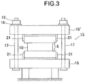
- Fig. 3 is a schematic diagram of the roll segment viewed from the casting direction of the strand, that is, a schematic diagram of a cross section taken perpendicular to the casting direction.
- the roll segment 15 includes a pair of frames, including a frame 16 and a frame 16', which hold five pairs of strand support rolls 6 with roll chocks 21 interposed therebetween.
- Four tie rods 17 are disposed (on both sides at an upstream portion and on both sides at a downstream portion) so as to extend through the frame 16 and the frame 16'.
- the distance between the frame 16 and the frame 16' is adjusted, that is, the reduction rate in the roll segment 15 is adjusted by driving worm jacks 19 disposed on the respective tie rods 17 using motors 20.
- the roll gap defined by the five pairs of strand support rolls 6 in the roll segment 15 is entirely adjusted by one operation.
- the worm jacks 19 self-lock with the molten steel static pressure of the strand 10 containing an unsolidified layer to act against the bulging force of the strand 10.
- the reduction rate is adjusted under the conditions where no strand 10 exists, that is, under the conditions where no load is exerted from the strand 10 on the strand support rolls 6 disposed in the roll segment 15.
- the amount by which the frame 16' is shifted by the worm jacks 19 is measured and controlled using the rotation rate of the worm jacks 19 to render the reduction rate of the roll segment 15 known.
- a disk spring 18 is disposed on each tie rod 17 between the frame 16' and the corresponding worm jack 19.
- Each disk spring 18 is not consisted of one disk spring piece, but is constituted of multiple disk spring pieces stacked one on top of another (the more disk spring pieces are stacked, the higher solidify the disk spring has).
- the disk spring 18 retains a certain thickness without shrinking.
- the disk spring 18 starts shrinking.
- the disk spring 18 shrinks in proportion to the load.
- the strand support rolls 6 other than the strand support rolls disposed in the soft reduction zone 14 have a roll segment structure.
- the soft reduction zone 14 illustrated in Fig. 1 has such a roll segment structure.
- the roll gap defined by three pairs of strand support rolls 6 disposed in each roll segment is entirely adjusted by one operation.
- the amount by which an upper frame (corresponding to the frame 16') is shifted by the worm jack is measured and controlled with the rotation rate of the worm jack, so that the reduction rate of each roll segment is known.
- the molten steel 9 poured into the mold 5 from the tundish 2 through the immersion nozzle 4 is cooled by the mold 5, forms a solidification shell 11, and becomes a strand 10 containing an unsolidified layer 12 inside.
- the strand 10 is continuously withdrawn downward from the mold 5 while being supported by the strand support rolls 6 disposed downward from the mold 5. While passing between the strand support rolls 6, the strand 10 is cooled by secondary cooling water in the secondary cooling zone, increases the thickness of the solidification shell 11, and is pressed down in the soft reduction zone 14, so that the strand 10 completely solidifies up to the inside on arrival at the solidification completion position 13.
- the completely solidified strand 10 is cut by the strand cutter 8 into a strand 10a.
- the strand 10 is pressed down in the soft reduction zone 14 at least during a period from the time point at which the strand thickness-wise middle portion has a temperature corresponding to the solid fraction of 0.1 to the time point at which the strand thickness-wise middle portion has a temperature corresponding to the flow-limit solid fraction.
- the flow-limit solid fraction is said to be 0.7 to 0.8 and thus the strand is pressed until the solid fraction of the strand thickness-wise middle portion arrives at a value in a range of 0.7 to 0.8.
- pressing the strand until the solid fraction of the strand thickness-wise middle portion arrives at or exceeds 0.8 is not a problem.
- the soft reduction After the solid fraction of the strand thickness-wise middle portion exceeds the flow-limit solid fraction, performing the soft reduction is meaningless since the unsolidified layer 12 no longer moves. Although the soft reduction is no longer effective, the soft reduction may be performed after the solid fraction of the strand thickness-wise middle portion exceeds the flow-limit solid fraction. On the other hand, once the solid fraction of the strand thickness-wise middle portion exceeds 0.1, concentrated molten steel may start flowing before soft reduction is started. The flow of concentrated molten steel causes center segregation, failing to obtain a sufficiently high center segregation reduction effect. For this reason, the soft reduction is to be started before the solid fraction of the strand thickness-wise middle portion arrives at 0.1.
- the solid fraction of the strand thickness-wise middle portion can be calculated by two-dimensional heat-transfer solidification calculation.
- the solid fraction is determined as zero before the start of solidification and as 1.0 after the completion of solidification.
- the position at which the solid fraction of the strand thickness-wise middle portion arrives at 1.0 corresponds to the solidification completion position 13.
- center segregation in the strand 10 is reduced by performing soft reduction on the strand 10 at a predetermined pressing speed at the end of the solidification of the molten steel 9.
- the pressing speed may fail to be controlled in the manner as designed since deformation of the solidification shell 11 caused by pressing may lower the pressing rate transmitted to the solidification interface of the strand 10 compared to the pressing rate at which the strand surface is pressed.
- the ratio of the pressing rate transmitted to the solidification interface of the strand 10 to the pressing rate at which the strand surface is pressed is referred to as pressing efficiency.
- the thickness of the solidification shell 11 particularly significantly serves as a cause that affects the pressing efficiency.
- the pressing efficiency decreases with increasing thickness of the solidification shell 11. Specifically, since the strand 10 is subjected to soft reduction at the end of the solidification, a strand 10 having a larger peripheral thickness would have a larger thickness of the solidification shell 11 during the soft reduction, whereby the pressing efficiency during the soft reduction is smaller.
- the peripheral thickness of the strand 10 is determined by the thickness extending in the direction of the short sides of the mold in the cavity (internal space in the mold) at the mold outlet.
- V denotes the strand withdrawal speed (m/min) and Z denotes the reduction rate (mm/m).
- D denotes the thickness (mm) of the cast target strand at a position immediately below a mold and Do denotes the thickness (mm) of a reference strand at a position immediately below a mold.
- the thickness coefficient ⁇ decreases with increasing strand thickness D. This means that the pressing efficiency decreases with increasing strand thickness D.
- the thickness Do of the reference strand at a position immediately under the mold is a strand thickness with which the thickness coefficient ⁇ expressed in the expression (5) is 1.
- the thickness Do is 187 mm in the case of the slab strand having a width of 2100 mm.
- the pressing efficiency changes in accordance with the difference of the strand thickness at the rate expressed by the expression (5).
- the degree of change in the pressing efficiency due to the difference of the strand thickness is compensated by adjusting the reduction rate in the soft reduction zone 14. Specifically, the reduction rate is increased when the pressing efficiency is small whereas the reduction rate is reduced when the pressing efficiency is large, so that the degree of change in the pressing efficiency is compensated.
- the thickness coefficient ⁇ expressed in the expression (5) is incorporated into the expression (4) to obtain the following expression (1) as a relational expression between the strand withdrawal speed, the thickness coefficient ⁇ , and the reduction rate: 0.3 / V ⁇ ⁇ ⁇ Z ⁇ 1.5 / V ⁇ ⁇
- the continuous casting is performed in accordance with the expression (1) and the expression (5) thus obtained when a strand 10 having a strand width of 2100 mm and a strand thickness in a range from 160 mm to 350 mm is continuously cast, the change of the pressing efficiency due to an increase or decrease of the strand thickness can be prevented.
- the occurrence of center segregation or porosity in the strand 10 can be prevented and the occurrence of inverted-V segregation or internal cracks in the strand 10 due to excessive pressing can be prevented.
- the thickness coefficient ⁇ in the expression (5) is the coefficient for the strand 10 having a fixed strand width of 2100 mm.
- the width of the strand 10 that is cast by the continuous slab casting machine 1 widely ranges from 1600 mm to 2400 mm.
- the inventors have decided to obtain the thickness coefficient ⁇ for all types of strands in the range of the thickness between 160 to 350 mm, the width between 1600 to 2400 mm, and the ratio of the width to the thickness (width /thickness) between 4 to 15.
- the main bodies that serve as resistance against pressing during the soft reduction in the soft reduction zone 14 are portions on the short sides of the strand that have finished solidifying.
- the absolute values of the dimension of these portions in the strand width direction are substantially equal to each other regardless of the width of the strand 10.
- the existence of the unsolidified layer 12 renders the pressing resistance so small as to be negligible compared to the portions on both ends on the short sides of the strand that have finished solidifying.
- the ratio of the completely solidified portions on the short sides of the strand to the strand width in the strand having a width of 1600 mm is larger than that in the strand having a width of 2100 mm, whereby the pressing resistance in the strand having a width of 1600 mm width is larger than that in the strand having a width of 2100 mm.
- the actual reduction rate for the strand having a width of 1600 mm may become smaller than the determined reduction rate with the effect of the reaction force against the pressing resistance exceeding the determined stress of the disk springs 18 and an increase of the roll gap.
- the thickness Do of the reference strand at a position immediately under the mold in the expression (2) was determined as 187 mm in the slab strand having a width in the range from 1600 mm to 2400 mm regardless of the width of the slab strand, as in the case of the slab strand having a width of 2100 mm.
- soft reduction is effective for preventing concentrated molten steel from flowing at the end portion of solidification
- the soft reduction may cause internal cracks at the solidification interface since pressing causes deformation of the strand 10. It is known that such internal cracks occur when the accumulated strain exerted on the solidification interface arrives at a predetermined value.
- the inventors have investigated the relationship between a total amount by which the strand 10 is pressed in soft reduction and the occurrence of internal cracks using an actual machine. As a result, the inventors have confirmed that, in order to prevent internal cracks in the strand 10, it is preferable that the total amount by which the strand 10 is pressed and the thickness of the cast target strand satisfy the relationship expressed by the following expression (3): Rt ⁇ D / Do ⁇ 10 / ⁇
- Rt in the expression (3) denotes the total amount (mm) by which the strand is pressed.
- the present invention indispensably includes continuous casting in which pressing conditions are so determined that the thickness of a cast target strand 10, the reduction rate of the soft reduction zone 14, and the strand withdrawal speed at which the strand is withdrawn fall within ranges that satisfy the relationship expressed by the expressions (1) and (2).
- the total amount by which the strand 10 is pressed and the thickness of the cast target strand are preferably determined so as to fall within ranges that satisfy the relationship expressed by the expression (3).
- the thickness of the solidification shell 11 and the solid fraction of the strand thickness-wise middle portion are calculated in advance using two-dimensional heat-transfer solidification calculation or the like under various casting conditions in the continuous casting operation.
- the rate of secondary cooling water or the strand withdrawal speed are adjusted so that the solid fraction of the strand thickness-wise middle portion at the time point when the strand enters the soft reduction zone 14 becomes 0.1 or smaller and the solid fraction of the strand thickness-wise middle portion at the time point when the strand exits from the soft reduction zone 14 arrives at or exceeds the flow-limit solid fraction.
- the pressing conditions are determined so that the thickness of the cast target strand 10, the reduction rate of the soft reduction zone 14, and the strand withdrawal speed fall within ranges that satisfy the relationship expressed by the above-described expressions (1) and (2).
- optimum pressing conditions can be easily calculated for strands 10 having different thicknesses, whereby requirements for production of steel products having various different specifications can be quickly fulfilled.
- a continuous casting machine used for testing is similar to the continuous casting machine 1 illustrated in Fig. 1 .
- Low carbon aluminum killed steel was cast using this continuous casting machine.
- Table 1 shows the results of investigation with regard to the degree of center segregation, the occurrence of porosity, or the occurrence of internal cracks in the cast strand, the results being obtained after performing the continuous casting method according to an embodiment of the present invention under the casting conditions for three types of strand thickness, including 200 mm, 250 mm, and 300 mm.
- Table 1 also shows the casting conditions and the investigation results of the tests performed as comparative examples for respective strand thicknesses under the conditions that fall out of the range of the present invention.
- the width of the strands is set at 2100 mm throughout the tests.
- the degree of center segregation of the strands used for evaluation in the test was measured in the following manner. Specifically, the carbon concentration in the cross section taken perpendicular to the withdrawal direction of each strand was analyzed at equal intervals in the thickness direction of the strand. The degree of center segregation was determined as C max /C 0 where C max denotes the maximum value of analysis in the thickness direction and C 0 denotes the carbon concentration analyzed in the molten steel taken from the tundish during casting.
- C max denotes the maximum value of analysis in the thickness direction
- C 0 denotes the carbon concentration analyzed in the molten steel taken from the tundish during casting.
- a strand that has a degree of center segregation closer to 1.0 is a more preferable strand having less center segregation.
- a strand having the degree of center segregation of 1.10 or higher is determined as having an undesirable level of center segregation.
- the strand withdrawal speed at which each of strands having different strand thicknesses is withdrawn was determined so that at least a region of the strand in which the thickness-wise middle portion has a solid fraction in the range from 0.1 to the flow-limit solid fraction is located in the soft reduction zone.
- the reduction rate was determined so as to satisfy the expressions (1) and (2).
- the reduction rate was so determined as to exceed the upper limit of the optimum range of the reduction rate determined by the expressions (1) and (2).
- the reduction rate was determined as being 0.5 mm/m although the optimum reduction rate obtained through the expressions (1) and (2) was 0.6 to 3.1 mm/m. Thus, the reduction rate was insufficient, the degree of center segregation exceeded 1.10, and the porosity was also observed inside the strand. Similarly, in Sample Nos. 5 and 10, the reduction rate was excessively small and the level of center segregation was undesirable.
Landscapes
- Engineering & Computer Science (AREA)
- Mechanical Engineering (AREA)
- Continuous Casting (AREA)
Abstract


Description
- The present invention relates to a continuous steel casting method that prevents component segregation that occurs at a thickness-wise middle portion of a continuously cast strand, that is, center segregation.
- During a final process of solidification in continuous casting of steel, unsolidified part of molten steel (referred to as "unsolidified layer") is withdrawn in accordance with solidification shrinkage, whereby the unsolidified part of the molten steel flows in the direction of withdrawal of the strand. In the unsolidified layer, solute elements such as carbon (C), phosphorus (P), sulfur (S), and manganese (Mn) are concentrated. When the concentrated molten steel flows in the middle portion of the strand and is solidified in that portion, so-called center segregation occurs. Examples of the causes of the flow of the concentrated molten steel at the end of the solidification include, besides the above-described solidification shrinkage, bulging of the strand between rolls due to molten steel static pressure and misalignment of strand support rolls.
- This center segregation impairs the quality of steel products, particularly, thick steel plates. For example, if a line pipe material for oil transportation or natural gas transportation has center segregation, the action of sour gas causes hydrogen induced cracking from the center segregation. Similar problems can occur also in structures including offshore structures, storage tank, and oil tanks. In these years, steel has been frequently required to be used under severe conditions such as under a low temperature or under a highly corrosive environment, whereby reduction of center segregation in the strand has been becoming increasingly important.
- Thus, a large number of countermeasures taken to reduce center segregation in the strand or render center segregation harmless have been developed throughout the procedure from the continuous casting process to the rolling process. One of such countermeasures known as being particularly effective in overcoming center segregation is a "solidification-terminal stage soft reduction method", in which a continuously cast strand containing an unsolidified layer inside is pressed down in a continuous casting machine. Here, the "solidification-terminal stage soft reduction method" is a method in which multiple pressing rolls are arranged at or around the solidification completion position of the strand and a continuously cast strand is gradually pressed down by the pressing rolls at a pressing speed approximately corresponding to the rate of solidification shrinkage so as to prevent occurrence of voids or flows of concentrated molten steel in the center portion of the strand, whereby the center segregation of the strand is suppressed.
- In order for the solidification-terminal stage soft reduction method to effectively prevent center segregation from occurring, it is important to appropriately determine the start time and the finish time of a period, within the final solidification period of the strand, during which the strand is being subjected to soft reduction and determine the pressing rate during the soft reduction period. Various types of methods for determining the times and the rate have been developed.
- For example, Patent Literature 1 describes a continuous casting method that includes subjecting soft reduction to a terminal solidification portion of a continuously cast strand and in which the rate at which the strand is pressed per unit time in a section in which the strand is subjected to soft reduction is determined by the strand surface temperature at the pressing start time and the thickness of the unsolidified layer of the strand at the press position.
-
Patent Literature 2 andPatent Literature 3 each describe a continuous casting continuous steel casting method while pressing a strand with multiple pairs of rolls within a region from the time point at which a thickness-wise middle portion of the bloom strand has a temperature corresponding to the solid fraction of 0.1 to 0.3 to the time point at which the thickness-wise middle portion has a temperature corresponding to the flow-limit solid fraction. In the method, the speed at which the strand is pressed is further increased toward the downstream side in the casting direction with increasing solid fraction at the strand thickness-wise middle portion. -
Patent Literature 4 describes a continuous steel casting method with an application of pressing force to the strand that is being cast. In the method, the pressing conditions are determined or adjusted on the basis of the information of the shape of a cross section of the strand taken perpendicular to the longitudinal direction of the strand and the information of the shape of an unsolidified portion in the cross section. -
- PTL 1: Japanese Unexamined Patent Application Publication No.
8-132203 - PTL 2: Japanese Unexamined Patent Application Publication No.
3-90263 - PTL 3: Japanese Unexamined Patent Application Publication No.
3-90259 - PTL 4: Japanese Unexamined Patent Application Publication No.
2003-71552 - The inventors have found the following facts from experience. In the continuous slab-strand casting involving solidification-terminal stage soft reduction method, in the case where the thickness of the cast target strand varies, the time at which the soft reduction is to be started and the time at which the soft reduction is to be finished do not change regardless of the thickness of the strand, whereas the optimum pressing speed in the range in which the pressing force is applied to the strand (referred to as "soft reduction zone") changes in accordance with the thickness of the strand.
- The thickness of the slab strand is determined by the thickness of the rolled steel product and the pressing ratio during rolling required for the specifications of the steel product (strand thickness/steel product thickness). Thus, when new specifications of a steel product are determined, the thickness of the strand is determined in accordance with the specifications. If a strand having the determined thickness has never been cast before with the solidification-terminal stage soft reduction method, there is a need for additionally determining an optimum pressing speed during the soft reduction for the strand thickness. Every time when the optimum pressing speed is to be determined, an optimum reduction rate in the soft reduction zone is determined through casting experiments using an actual machine under the settings of various different levels of reduction rate, which requires significant time and cost. Specifically, the achievement of a method for simply obtaining an optimum reduction rate in the soft reduction zone in accordance with the thickness of the slab strand has been a challenge.
- Here, the "reduction rate" refers to the state of the degree of a roll opening determined in such a manner that the distance between opposing rolls (referred to as "the roll gap") gradually decreases toward the downstream side in the casting direction. The reduction rate is usually expressed by the amount by which the degree of the roll opening decreases per 1 m (mm/m). The value obtained by multiplying the reduction rate (mm/m) by the strand withdrawal speed (m/min) is calculated as the pressing speed (mm/min).
- The inventors have verified the usefulness of the above-described cited documents from the standpoint of the above-described problem that the inventors are trying to solve.
- Patent Literature 1 focuses an attention on the unsolidified layer thickness of the strand as an indicator for effectively performing soft reduction. According to Patent Literature 1, this is based on the finding that the pressing rate determined for the pressing rolls is transmitted in a smaller rate to the interface of solid and liquid phases of the strand (hereinafter the rate is referred to as "pressing efficiency") on the casting downstream side, that is, with decreasing unsolidified layer thickness of the strand. However, the experience of the inventors has revealed that the center segregation becomes apparent in a center region of the strand having an unsolidified layer thickness of approximately 10 mm or smaller. According to the relationship between the unsolidified layer thickness D and the pressing speed required per unit time shown in
Fig. 1 of Patent Literature 1, the difference between a pressing speed required for the unsolidified layer thickness of 10 mm and a pressing speed required for the unsolidified layer thickness of 0 mm is approximately 10% at most. [Example] in Patent Literature 1 has described only the test results for one strand thickness (250 mm). Thus, whether the optimum pressing conditions described in Patent Literature 1 are also effective for different strand thicknesses remains in question. - In
Patent Literature 2 andPatent Literature 3, the sizes of the strands used in the test in thickness and width range between three types of 300 mm × 500 mm, 162 mm × 162 mm, and 380 mm × 560 mm. All the strands having the above sizes relate to the soft-reduction casting of a bloom strand. Since a bloom strand has a ratio between the width and the thickness of the cross section taken perpendicular to the withdrawal direction of the strand (width/thickness) smaller than that of a slab strand, the pressing efficiency in the soft reduction at the end of the solidification of a bloom strand is smaller than that in the case of a slab strand. Accordingly, the pressing rate increases further toward the end of the solidification. The pressing rate is approximately two to three times as large as that in the case of the slab strand in Patent Literature 1. These pressing conditions cannot be directly used in the soft reduction of the slab strand. - In Patent Literature 1 to
Patent Literature 3, the reduction rate in the soft reduction zone is varied in the casting withdrawal direction and thus the roll gap of strand support rolls is determined with complexity, entailing complexity of the equipment structure for practice with an actual machine. -
Patent Literature 4 is directed toward a bloom strand. InPatent Literature 4, the soft reduction conditions are determined on the basis of information of the shape of the cross section taken perpendicular to the longitudinal direction of the strand, that is, the width and the thickness of the strand. Here, the soft reduction conditions are determined using the ratio between the width and the thickness of the strand as references and on the basis of the amount of change between the references and the ratio between the width and the thickness of the unsolidified portion of the strand. The soft reduction conditions are not determined by directly using the thickness of the strand. In the case of the bloom strand, an unsolidified layer of the strand can have a flat shape either in the lateral direction or in the vertical direction depending on the cooling ratio between the upper and lower surfaces of the strand inside the continuous casting machine or the cooling ratio between the left and right surfaces of the strand inside the continuous casting machine. Thus, the conditions inPatent Literature 4 are determined in the above-described manner for the purposes of enabling an optimum soft reduction in either of these cases. - A slab strand toward which the inventors are directed has a far larger long side than a short side and the direction in which the unsolidified layer extends flat does not change; the unsolidified layer is always flat in the lateral direction of the strand. Thus,
Patent Literature 4 is less useful against the problems of the inventors. - As described above, none of Patent Literature 1 to
Patent Literature 4 leads to solutions for the problems of the inventors, and thus development of a new way is required. - The present invention has been made in view of the above-described circumstances and aims to provide a continuous steel casting method with which soft reduction conditions can be determined in accordance with the thickness of a strand, thereby preventing an occurrence of center segregation in the strand due to an insufficient pressing rate or an occurrence of internal cracks in the strand due to an excessively high pressing rate. Solution to Problem
- The summary of the present invention for solving the above-described problems is described as follows:
- [1] A continuous steel casting method for continuously casting a strand having a thickness of 160 mm to 350 mm, a width of 1600 mm to 2400 mm, and a ratio of the width to the thickness (width/thickness) of 4 to 15, the method including:
- pressing a region of the strand in a soft reduction zone in which a plurality of pairs of strand support rolls that apply pressing force to the strand are disposed, the region of the strand extending from a point of time at which a strand thickness-wise middle portion has a temperature corresponding to a solid fraction of 0.1 to a point of time at which a strand thickness-wise middle portion has a temperature corresponding to a flow-limit solid fraction. A thickness of the cast target strand, a reduction rate of the soft reduction zone, and a strand withdrawal speed at which the strand is withdrawn satisfy a relationship expressed by expressions (1) and (2) below:


In the expressions (1) and (2), V denotes the strand withdrawal speed (m/min), α denotes a thickness coefficient (dimensionless), Z denotes the reduction rate (mm/m), D denotes a thickness (mm) of the cast target strand at a position immediately below a mold, Do denotes a thickness (mm, Do = 187 mm) of a standard strand at a position immediately below a mold, and β and γ are coefficients determined by a width W (mm) of the cast target strand according to the following ranges of the width W of the strand:



- pressing a region of the strand in a soft reduction zone in which a plurality of pairs of strand support rolls that apply pressing force to the strand are disposed, the region of the strand extending from a point of time at which a strand thickness-wise middle portion has a temperature corresponding to a solid fraction of 0.1 to a point of time at which a strand thickness-wise middle portion has a temperature corresponding to a flow-limit solid fraction. A thickness of the cast target strand, a reduction rate of the soft reduction zone, and a strand withdrawal speed at which the strand is withdrawn satisfy a relationship expressed by expressions (1) and (2) below:
- [2] The continuous steel casting method according to the above paragraph [1], wherein the thickness of the cast target strand and a total amount by which the strand is pressed satisfy a relationship expressed by an expression (3) below:

In the expression (3), Rt denotes a total amount (mm) by which the strand is pressed, D denotes the thickness (mm) of the cast target strand at the position immediately below the mold, Do denotes the thickness (mm, Do = 187 mm) of the standard strand at the position immediately below the mold, and α denotes a thickness coefficient (dimensionless). Advantageous Effects of Invention - According to the present invention, the pressing conditions are so determined that the thickness of the cast target strand, the reduction rate in a soft reduction zone, and the withdrawal speed of the strand fall within ranges that satisfy the relationship of the expression (1) and the expression (2) in order to reduce center segregation in the slab strand when the strand is continuously cast while the strand is applied with pressing force at the pressing rate approximately corresponding to the rate of solidification shrinkage in the soft reduction zone. Thus, even in the case where the thickness of the strand varies, optimum pressing conditions can be simply obtained without consuming a lot of time and cost such as performing actual experiments under various different levels. This invention thus enables rapid responses to requirements of manufacturing various different steel products having different specifications, thereby bringing about industrial useful effects. Brief Description of Drawings
-
- [
Fig. 1] Fig. 1 is a schematic diagram of a continuous slab casting machine used for embodying the present invention, viewed from the side. - [
Fig. 2] Fig. 2 is a schematic diagram of an example of a roll segment constituting a soft reduction zone of the continuous slab casting machine, viewed from the side of the continuous casting machine. - [
Fig. 3] Fig. 3 is a schematic diagram of the roll segment illustrated inFig. 2 , viewed from the casting direction of the strand, that is, a schematic diagram of the roll segment in a cross section taken perpendicular to the casting direction. - Hereinbelow, the present invention is specifically described with reference to the appended drawings.
Fig. 1 is a schematic diagram of a continuous slab casting machine used for embodying the present invention, viewed from the side. - As illustrated in
Fig. 1 , the continuous slab casting machine 1 includes amold 5 for receiving and solidifying molten steel 9 and for forming an outer shell shape of astrand 10. Atundish 2 is disposed at an appropriate position above themold 5 to transmit the molten steel 9 provided from a ladle (not illustrated) to themold 5. A slidingnozzle 3 is disposed at the bottom portion of thetundish 2 to adjust the flow rate of the molten steel 9. Animmersion nozzle 4 is disposed at the lower surface of the slidingnozzle 3. - Below the
mold 5, on the other hand, multiple pairs of strand support rolls 6 including support rolls, guide rolls, and pinch rolls are disposed. In a secondary cooling zone, spray nozzles such as a water spray nozzle or an air mist spray nozzle (not illustrated) are disposed in gaps between strand support rolls 6 adjacent in the casting direction. Thestrand 10 is cooled by the cooling water (also referred to as "secondary cooling water") sprayed from the spray nozzles in the secondary cooling zone while being withdrawn. On the downstream side of the strand support rolls 6 at the end in the casting direction, multiple transport rolls 7 are disposed to transport thecast strand 10. Above the transport rolls 7, astrand cutter 8 is disposed to cut thecast strand 10 into astrand 10a having a predetermined length. - In an area extending from the upstream side and the downstream side of a
solidification completion position 13 of thestrand 10 in the casting direction, asoft reduction zone 14 constituted by a group of multiple pairs of strand support rolls is formed. In thesoft reduction zone 14, the distance between the opposing strand support rolls across the strand 10 (the distance is referred to as a "roll gap") gradually decreases toward the downstream side in the casting direction, specifically, the reduction rate (the state of the roll gap that gradually decreases toward the downstream side in the casting direction) is provided. Soft reduction can be performed on thestrand 10 over the entire area or a selected area of thesoft reduction zone 14. Spray nozzles are also disposed in gaps between strand support rolls in thesoft reduction zone 14 to cool thestrand 10. Here, the strand support rolls 6 disposed in thesoft reduction zone 14 are also referred to as pressing rolls. - Normally, the reduction rate is expressed by an amount of reduction of the roll gap per meter in the casting direction, that is, "mm/m". Thus, the pressing speed (mm/min) of the
strand 10 in thesoft reduction zone 14 is obtained by multiplying the reduction rate (mm/m) by the strand withdrawal speed (m/min). - In the continuous slab casting machine 1 illustrated in
Fig. 1 , thesoft reduction zone 14 is constituted of three roll segments connected in the casting direction, each of which is constituted of three pairs of strand support rolls 6. In the present invention, however, thesoft reduction zone 14 does not have to be constituted of three roll segments. Thesoft reduction zone 14 may be constituted of one roll segment or two roll segments, or even four roll segments. In the continuous slab casting machine 1 illustrated inFig. 1 , each roll segment is constituted of three pairs of strand support rolls 6. However, each roll segment may be constituted of any number of pairs of strand support rolls 6 not smaller than two pairs. -
Fig. 2 andFig. 3 illustrate an example of a roll segment constituting thesoft reduction zone 14.Fig. 2 andFig. 3 illustrate an example of aroll segment 15 in which five pairs of strand support rolls 6 are provided as pressing rolls.Fig. 2 is a schematic diagram of the example of a roll segment viewed from the side of the continuous casting machine.Fig. 3 is a schematic diagram of the roll segment viewed from the casting direction of the strand, that is, a schematic diagram of a cross section taken perpendicular to the casting direction. - As illustrated in
Fig. 2 andFig. 3 , theroll segment 15 includes a pair of frames, including aframe 16 and a frame 16', which hold five pairs of strand support rolls 6 withroll chocks 21 interposed therebetween. Fourtie rods 17 are disposed (on both sides at an upstream portion and on both sides at a downstream portion) so as to extend through theframe 16 and the frame 16'. The distance between theframe 16 and the frame 16' is adjusted, that is, the reduction rate in theroll segment 15 is adjusted by drivingworm jacks 19 disposed on therespective tie rods 17 usingmotors 20. In this case, the roll gap defined by the five pairs of strand support rolls 6 in theroll segment 15 is entirely adjusted by one operation. - In casting, the worm jacks 19 self-lock with the molten steel static pressure of the
strand 10 containing an unsolidified layer to act against the bulging force of thestrand 10. Thus, the reduction rate is adjusted under the conditions where nostrand 10 exists, that is, under the conditions where no load is exerted from thestrand 10 on the strand support rolls 6 disposed in theroll segment 15. The amount by which the frame 16' is shifted by the worm jacks 19 is measured and controlled using the rotation rate of the worm jacks 19 to render the reduction rate of theroll segment 15 known. - A
disk spring 18 is disposed on eachtie rod 17 between the frame 16' and thecorresponding worm jack 19. Eachdisk spring 18 is not consisted of one disk spring piece, but is constituted of multiple disk spring pieces stacked one on top of another (the more disk spring pieces are stacked, the higher solidify the disk spring has). Unless a predetermined or heavier load acts on thedisk spring 18, thedisk spring 18 retains a certain thickness without shrinking. When a predetermined load acts on thedisk spring 18, thedisk spring 18 starts shrinking. When a load exceeding the predetermined load acts on thedisk spring 18, thedisk spring 18 shrinks in proportion to the load. - For example, when the
strand 10 finishes solidifying within the range of theroll segment 15, pressing the completely solidifiedstrand 10 causes an excessive load on theroll segment 15. When such an excessive load is to be exerted on theroll segment 15, the disk springs 18 shrink so that the frame 16' is released, that is, the roll gap increases so as not to exert an excessive load on theroll segment 15. Theframe 16 disposed at the bottom side is fixed to the foundation of the continuous casting machine and does not move during casting. - Although not illustrated, the strand support rolls 6 other than the strand support rolls disposed in the
soft reduction zone 14 have a roll segment structure. - The
soft reduction zone 14 illustrated inFig. 1 has such a roll segment structure. Thus, the roll gap defined by three pairs of strand support rolls 6 disposed in each roll segment is entirely adjusted by one operation. In this case, the amount by which an upper frame (corresponding to the frame 16') is shifted by the worm jack is measured and controlled with the rotation rate of the worm jack, so that the reduction rate of each roll segment is known. - In the continuous slab casting machine 1 having the above-described structure, the molten steel 9 poured into the
mold 5 from thetundish 2 through theimmersion nozzle 4 is cooled by themold 5, forms asolidification shell 11, and becomes astrand 10 containing anunsolidified layer 12 inside. Thestrand 10 is continuously withdrawn downward from themold 5 while being supported by the strand support rolls 6 disposed downward from themold 5. While passing between the strand support rolls 6, thestrand 10 is cooled by secondary cooling water in the secondary cooling zone, increases the thickness of thesolidification shell 11, and is pressed down in thesoft reduction zone 14, so that thestrand 10 completely solidifies up to the inside on arrival at thesolidification completion position 13. The completely solidifiedstrand 10 is cut by thestrand cutter 8 into astrand 10a. - In the present invention, the
strand 10 is pressed down in thesoft reduction zone 14 at least during a period from the time point at which the strand thickness-wise middle portion has a temperature corresponding to the solid fraction of 0.1 to the time point at which the strand thickness-wise middle portion has a temperature corresponding to the flow-limit solid fraction. The flow-limit solid fraction is said to be 0.7 to 0.8 and thus the strand is pressed until the solid fraction of the strand thickness-wise middle portion arrives at a value in a range of 0.7 to 0.8. Thus, pressing the strand until the solid fraction of the strand thickness-wise middle portion arrives at or exceeds 0.8 is not a problem. After the solid fraction of the strand thickness-wise middle portion exceeds the flow-limit solid fraction, performing the soft reduction is meaningless since theunsolidified layer 12 no longer moves. Although the soft reduction is no longer effective, the soft reduction may be performed after the solid fraction of the strand thickness-wise middle portion exceeds the flow-limit solid fraction. On the other hand, once the solid fraction of the strand thickness-wise middle portion exceeds 0.1, concentrated molten steel may start flowing before soft reduction is started. The flow of concentrated molten steel causes center segregation, failing to obtain a sufficiently high center segregation reduction effect. For this reason, the soft reduction is to be started before the solid fraction of the strand thickness-wise middle portion arrives at 0.1. - The solid fraction of the strand thickness-wise middle portion can be calculated by two-dimensional heat-transfer solidification calculation. Here, the solid fraction is determined as zero before the start of solidification and as 1.0 after the completion of solidification. The position at which the solid fraction of the strand thickness-wise middle portion arrives at 1.0 corresponds to the
solidification completion position 13. - It is generally well known that center segregation in the
strand 10 is reduced by performing soft reduction on thestrand 10 at a predetermined pressing speed at the end of the solidification of the molten steel 9. During the soft reduction, however, the pressing speed may fail to be controlled in the manner as designed since deformation of thesolidification shell 11 caused by pressing may lower the pressing rate transmitted to the solidification interface of thestrand 10 compared to the pressing rate at which the strand surface is pressed. Here, the ratio of the pressing rate transmitted to the solidification interface of thestrand 10 to the pressing rate at which the strand surface is pressed (pressing rate transmitted to the solidification interface/pressing rate at which the strand surface is pressed) is referred to as pressing efficiency. - The thickness of the
solidification shell 11 particularly significantly serves as a cause that affects the pressing efficiency. The pressing efficiency decreases with increasing thickness of thesolidification shell 11. Specifically, since thestrand 10 is subjected to soft reduction at the end of the solidification, astrand 10 having a larger peripheral thickness would have a larger thickness of thesolidification shell 11 during the soft reduction, whereby the pressing efficiency during the soft reduction is smaller. The peripheral thickness of thestrand 10 is determined by the thickness extending in the direction of the short sides of the mold in the cavity (internal space in the mold) at the mold outlet. - In order to reduce center segregation with soft reduction performed under optimum pressing conditions regardless of a strand thickness when a
strand 10 that has a fixed strand width of 2100 mm and a strand thickness of 160 mm to 350 mm is continuously cast, the inventors have firstly calculated, through casting experiments using an actual machine, an optimum range of the reduction rate in thesoft reduction zone 14 when astrand 10 having a thickness of 200 mm is continuously cast. As a result of the experiments, the optimum reduction rate for thestrand 10 having a thickness of 200 mm has been found to fall within the range expressed by the following expression (4):
- In the expression (4), V denotes the strand withdrawal speed (m/min) and Z denotes the reduction rate (mm/m).
- Subsequently, in order to incorporate into the expression (4) a correction value that compensates the pressing efficiency for the effect of the thickness of the
strand 10, a numerical simulation relating to the deformation of thestrand 10 during soft reduction was performed for various different strand thicknesses ranging between 160 mm to 350 mm. From the simulation results, the relationship between the thickness of thestrand 10 and the pressing efficiency was obtained and a thickness coefficient α (dimensionless) was derived as a primary approximate expression of the strand thickness as the expression (5) below:
- In the expression (5), D denotes the thickness (mm) of the cast target strand at a position immediately below a mold and Do denotes the thickness (mm) of a reference strand at a position immediately below a mold.
- The thickness coefficient α decreases with increasing strand thickness D. This means that the pressing efficiency decreases with increasing strand thickness D. Here, the thickness Do of the reference strand at a position immediately under the mold is a strand thickness with which the thickness coefficient α expressed in the expression (5) is 1. The thickness Do is 187 mm in the case of the slab strand having a width of 2100 mm.
- When the thickness of the
cast target strand 10 is different from the reference thickness of 187 mm, the pressing efficiency changes in accordance with the difference of the strand thickness at the rate expressed by the expression (5). In this invention, the degree of change in the pressing efficiency due to the difference of the strand thickness is compensated by adjusting the reduction rate in thesoft reduction zone 14. Specifically, the reduction rate is increased when the pressing efficiency is small whereas the reduction rate is reduced when the pressing efficiency is large, so that the degree of change in the pressing efficiency is compensated. In other words, the thickness coefficient α expressed in the expression (5) is incorporated into the expression (4) to obtain the following expression (1) as a relational expression between the strand withdrawal speed, the thickness coefficient α, and the reduction rate:
- If the continuous casting is performed in accordance with the expression (1) and the expression (5) thus obtained when a
strand 10 having a strand width of 2100 mm and a strand thickness in a range from 160 mm to 350 mm is continuously cast, the change of the pressing efficiency due to an increase or decrease of the strand thickness can be prevented. Thus, the occurrence of center segregation or porosity in thestrand 10 can be prevented and the occurrence of inverted-V segregation or internal cracks in thestrand 10 due to excessive pressing can be prevented. - The thickness coefficient α in the expression (5) is the coefficient for the
strand 10 having a fixed strand width of 2100 mm. On the other hand, the width of thestrand 10 that is cast by the continuous slab casting machine 1 widely ranges from 1600 mm to 2400 mm. Thus, the inventors have decided to obtain the thickness coefficient α for all types of strands in the range of the thickness between 160 to 350 mm, the width between 1600 to 2400 mm, and the ratio of the width to the thickness (width /thickness) between 4 to 15. - The main bodies that serve as resistance against pressing during the soft reduction in the
soft reduction zone 14 are portions on the short sides of the strand that have finished solidifying. When thestrand 10 has an even thickness, the absolute values of the dimension of these portions in the strand width direction are substantially equal to each other regardless of the width of thestrand 10. In the region of the strand containing theunsolidified layer 12 inside, the existence of theunsolidified layer 12 renders the pressing resistance so small as to be negligible compared to the portions on both ends on the short sides of the strand that have finished solidifying. - Specifically, for example, the ratio of the completely solidified portions on the short sides of the strand to the strand width in the strand having a width of 1600 mm is larger than that in the strand having a width of 2100 mm, whereby the pressing resistance in the strand having a width of 1600 mm width is larger than that in the strand having a width of 2100 mm. Thus, in the case where the same reduction rate in the
soft reduction zone 14 is determined for a strand having a width of 1600 mm and for a strand having a width of 2100 mm, the actual reduction rate for the strand having a width of 1600 mm may become smaller than the determined reduction rate with the effect of the reaction force against the pressing resistance exceeding the determined stress of the disk springs 18 and an increase of the roll gap. - To address this situation, numerical simulations similar to the numerical simulation performed on the strand having a width of 2100 mm were also performed on strands having strand widths of 1700 mm, 1900 mm, and 2300 mm to obtain thickness coefficients α for these strands. Each thickness coefficient α was expressed by the following expression (2) including coefficients P and γ, which are determined by the width W (mm) of a cast target strand:

- From the results of the numerical simulations, the coefficient P and the coefficient γ in the expression (2) were found to take the following values in accordance with the width W (mm) of the cast target strand:



- Here, P = -0.58 and γ = 1.58 when 2000 < W ≤ 2200 as illustrated in the expression (5).
- Here, the thickness Do of the reference strand at a position immediately under the mold in the expression (2) was determined as 187 mm in the slab strand having a width in the range from 1600 mm to 2400 mm regardless of the width of the slab strand, as in the case of the slab strand having a width of 2100 mm.
- Although soft reduction is effective for preventing concentrated molten steel from flowing at the end portion of solidification, the soft reduction may cause internal cracks at the solidification interface since pressing causes deformation of the
strand 10. It is known that such internal cracks occur when the accumulated strain exerted on the solidification interface arrives at a predetermined value. - Thus, the inventors have investigated the relationship between a total amount by which the
strand 10 is pressed in soft reduction and the occurrence of internal cracks using an actual machine. As a result, the inventors have confirmed that, in order to prevent internal cracks in thestrand 10, it is preferable that the total amount by which thestrand 10 is pressed and the thickness of the cast target strand satisfy the relationship expressed by the following expression (3):
- Here, Rt in the expression (3) denotes the total amount (mm) by which the strand is pressed.
- Specifically, the present invention indispensably includes continuous casting in which pressing conditions are so determined that the thickness of a
cast target strand 10, the reduction rate of thesoft reduction zone 14, and the strand withdrawal speed at which the strand is withdrawn fall within ranges that satisfy the relationship expressed by the expressions (1) and (2). At this time, the total amount by which thestrand 10 is pressed and the thickness of the cast target strand are preferably determined so as to fall within ranges that satisfy the relationship expressed by the expression (3). - In addition, the thickness of the
solidification shell 11 and the solid fraction of the strand thickness-wise middle portion are calculated in advance using two-dimensional heat-transfer solidification calculation or the like under various casting conditions in the continuous casting operation. Thus, the rate of secondary cooling water or the strand withdrawal speed are adjusted so that the solid fraction of the strand thickness-wise middle portion at the time point when the strand enters thesoft reduction zone 14 becomes 0.1 or smaller and the solid fraction of the strand thickness-wise middle portion at the time point when the strand exits from thesoft reduction zone 14 arrives at or exceeds the flow-limit solid fraction. - As described above, according to the invention, the pressing conditions are determined so that the thickness of the
cast target strand 10, the reduction rate of thesoft reduction zone 14, and the strand withdrawal speed fall within ranges that satisfy the relationship expressed by the above-described expressions (1) and (2). Thus, optimum pressing conditions can be easily calculated forstrands 10 having different thicknesses, whereby requirements for production of steel products having various different specifications can be quickly fulfilled. - Hereinbelow, the present invention is further described in detail using embodiments.
- A continuous casting machine used for testing is similar to the continuous casting machine 1 illustrated in
Fig. 1 . Low carbon aluminum killed steel was cast using this continuous casting machine. Table 1 shows the results of investigation with regard to the degree of center segregation, the occurrence of porosity, or the occurrence of internal cracks in the cast strand, the results being obtained after performing the continuous casting method according to an embodiment of the present invention under the casting conditions for three types of strand thickness, including 200 mm, 250 mm, and 300 mm. Table 1 also shows the casting conditions and the investigation results of the tests performed as comparative examples for respective strand thicknesses under the conditions that fall out of the range of the present invention. The width of the strands is set at 2100 mm throughout the tests.[Table 1] Sample No. Strand Thickness (mm) Water Flow Rate (L/steel-kg) Strand Withdraw Speed (m/min) Reduction Rate (mm/m) Total Amount Pressed (mm) Degree of Center Segregation (Cmax/C0) Porosity Internal Crack Note 1 200 1.6 1.40 0.8 4.8 1.065 None None Example 2 1.4 1.60 0.8 8.0 1.061 None None Example 3 1.2 1.80 0.5 4.0 1.046 None None Example 4 1.6 1.40 1.5 20.0 1.103 None Present Comparative Example 5 1.5 1.40 0.2 2.0 1.121 Present None Comparative Example 6 250 1.6 1.10 0.7 7.0 1.044 None None Example 7 1.3 1.25 0.6 6.0 1.046 None None Example 8 1.1 1.60 0.4 3.2 1.057 None None Example 9 1.4 1.60 2.0 24.0 1.121 None Present Comparative Example 10 1.4 1.40 0.2 2.0 1.133 Present None Comparative Example 11 300 1.1 0.75 1.2 12.0 1.042 None None Example 12 0.9 0.75 1.1 11.0 1.030 None None Example 13 0.8 0.90 1.1 11.0 1.069 None None Example 14 0.8 0.90 3.0 15.0 1.098 None Present Comparative Example 15 0.9 0.75 0.5 5.0 1.132 Present None Comparative Example - The degree of center segregation of the strands used for evaluation in the test was measured in the following manner. Specifically, the carbon concentration in the cross section taken perpendicular to the withdrawal direction of each strand was analyzed at equal intervals in the thickness direction of the strand. The degree of center segregation was determined as Cmax/C0 where Cmax denotes the maximum value of analysis in the thickness direction and C0 denotes the carbon concentration analyzed in the molten steel taken from the tundish during casting. Thus, a strand that has a degree of center segregation closer to 1.0 is a more preferable strand having less center segregation. In this invention, a strand having the degree of center segregation of 1.10 or higher is determined as having an undesirable level of center segregation.
- Whether porosity or internal cracks of each strand is/are present was determined through microscopic observation of the cross section of the strand taken perpendicular to the withdrawal direction of the strand at or around a center portion of the strand thickness.
- The strand withdrawal speed at which each of strands having different strand thicknesses is withdrawn was determined so that at least a region of the strand in which the thickness-wise middle portion has a solid fraction in the range from 0.1 to the flow-limit solid fraction is located in the soft reduction zone. In Sample Nos. 1 to 3, Sample Nos. 6 to 8, and Sample Nos. 11 to 13, the reduction rate was determined so as to satisfy the expressions (1) and (2). In Sample Nos. 4, 9, and 14 tested as comparative examples, the reduction rate was so determined as to exceed the upper limit of the optimum range of the reduction rate determined by the expressions (1) and (2). In Sample Nos. 5, 10, and 15, the reduction rate was so determined as to fall below the lower limit of the optimum range of the reduction rate determined by the expressions (1) and (2). In Sample Nos. 4 and 9, the reduction rate was determined so that the total amount pressed exceeds the upper limit of the expression (3).
- As is clear from the degree of center segregation shown in Table 1, the degree of center segregation in each of Sample Nos. 1 to 3, Sample Nos. 6 to 8, and Sample Nos. 11 to 13 within the scope of the invention was below 1.10, which was preferable. Neither porosity nor internal cracks were found in each of the above strands.
- In Sample No. 4 tested as a comparative example, the reduction rate was determined as an excessive value of 1.5 mm/m although the optimum reduction rate obtained through the expressions (1) and (2) was 0.2 to 1.1 mm/m, whereby the degree of center segregation exceeded 1.10. In addition, the total amount pressed was also excessive, whereby internal cracks occurred in the strand. Similarly, Sample Nos. 9 and 14 each had an excessive reduction rate and a high degree of center segregation, and inverted-V segregation was also partially observed.
- In Sample No. 15, the reduction rate was determined as being 0.5 mm/m although the optimum reduction rate obtained through the expressions (1) and (2) was 0.6 to 3.1 mm/m. Thus, the reduction rate was insufficient, the degree of center segregation exceeded 1.10, and the porosity was also observed inside the strand. Similarly, in Sample Nos. 5 and 10, the reduction rate was excessively small and the level of center segregation was undesirable.
-
- 1
- continuous slab casting machine
- 2
- tundish
- 3
- sliding nozzle
- 4
- immersion nozzle
- 5
- mold
- 6
- strand support roll
- 7
- transport roll
- 8
- slab cutter
- 9
- molten steel
- 10
- strand
- 11
- solidification shell
- 12
- unsolidified layer
- 13
- solidification completion position
- 14
- soft reduction zone
- 15
- roll segment
- 16
- frame
- 17
- tie rod
- 18
- disk spring
- 19
- worm jack
- 20
- motor
- 21
- roll chock
Claims (2)
- A continuous steel casting method for continuously casting a strand having a thickness of 160 mm to 350 mm, a width of 1600 mm to 2400 mm, and a ratio of the width to the thickness (width/thickness) of 4 to 15, the method comprising:pressing a region of the strand in a soft reduction zone in which a plurality of pairs of strand support rolls that apply pressing force to the strand are disposed, the region of the strand extending from a point at which a strand thickness-wise middle portion has a temperature corresponding to a solid fraction of 0.1 to a point at which a strand thickness-wise middle portion has a temperature corresponding to a flow-limit solid fraction, whereina thickness of the cast target strand, a reduction rate of the soft reduction zone, and a strand withdrawal speed at which the strand is withdrawn satisfy a relationship expressed by expressions (1) and (2) below:


in the expressions (1) and (2),V denotes the strand withdrawal speed (m/min),α denotes a thickness coefficient (dimensionless),Z denotes the reduction rate (mm/m),D denotes a thickness (mm) of the cast target strand at a position immediately below a mold,Do denotes a thickness (mm, Do = 187 mm) of a standard strand at a position immediately below a mold, andβ and γ are coefficients determined by a width W (mm) of the cast target strand according to the following ranges of the width W of the strand:


- The continuous steel casting method according to Claim 1, wherein the thickness of the cast target strand and a total amount by which the strand is pressed satisfy a relationship expressed by an expression (3) below:
 Rt denotes a total amount (mm) by which the strand is pressed,D denotes the thickness (mm) of the cast target strand at the position immediately below the mold,Do denotes the thickness (mm, Do = 187 mm) of the standard strand at the position immediately below the mold, andα denotes a thickness coefficient (dimensionless).
Applications Claiming Priority (1)
| Application Number | Priority Date | Filing Date | Title |
|---|---|---|---|
| PCT/JP2014/006415 WO2016103293A1 (en) | 2014-12-24 | 2014-12-24 | Continuous casting method for steel |
Publications (3)
| Publication Number | Publication Date |
|---|---|
| EP3219408A1 true EP3219408A1 (en) | 2017-09-20 |
| EP3219408A4 EP3219408A4 (en) | 2017-10-04 |
| EP3219408B1 EP3219408B1 (en) | 2018-11-07 |
Family
ID=56149397
Family Applications (1)
| Application Number | Title | Priority Date | Filing Date |
|---|---|---|---|
| EP14908904.7A Active EP3219408B1 (en) | 2014-12-24 | 2014-12-24 | Continuous casting method for steel |
Country Status (7)
| Country | Link |
|---|---|
| US (1) | US10543527B2 (en) |
| EP (1) | EP3219408B1 (en) |
| KR (1) | KR101930660B1 (en) |
| CN (1) | CN107000045B (en) |
| BR (1) | BR112015008906B1 (en) |
| RU (1) | RU2678112C2 (en) |
| WO (1) | WO2016103293A1 (en) |
Cited By (3)
| Publication number | Priority date | Publication date | Assignee | Title |
|---|---|---|---|---|
| CN112605361A (en) * | 2020-12-11 | 2021-04-06 | 湖南华菱涟钢薄板有限公司 | Control method for transverse crack defect on surface of 75Cr1 steel |
| US11077492B2 (en) | 2018-03-02 | 2021-08-03 | Jfe Steel Corporation | Continuous steel casting method |
| US11471936B2 (en) | 2018-04-17 | 2022-10-18 | Jfe Steel Corporation | Continuous casting method of steel |
Families Citing this family (3)
| Publication number | Priority date | Publication date | Assignee | Title |
|---|---|---|---|---|
| EP3889276B1 (en) | 2019-01-25 | 2024-06-26 | JFE Steel Corporation | Method for manufacturing high-manganese steel cast slab and method for manufacturing high-manganese steel slab or steel sheet |
| CN111545719A (en) * | 2020-05-11 | 2020-08-18 | 江苏联峰实业有限公司 | A kind of steel billet gradient continuous casting equipment and its continuous casting process |
| CN114169261B (en) * | 2021-11-23 | 2022-10-28 | 中国石油大学(北京) | Multi-fracture parameter inversion method and device based on G function curve analysis |
Family Cites Families (25)
| Publication number | Priority date | Publication date | Assignee | Title |
|---|---|---|---|---|
| JPS6233048A (en) | 1985-08-03 | 1987-02-13 | Nippon Steel Corp | Continuous casting method |
| DE3676753D1 (en) | 1985-08-03 | 1991-02-14 | Nippon Steel Corp | CONTINUOUS METHOD. |
| JPH0390259A (en) | 1989-08-31 | 1991-04-16 | Nippon Steel Corp | Continuous casting method |
| JPH078421B2 (en) | 1989-08-31 | 1995-02-01 | 新日本製鐵株式会社 | Continuous casting method |
| JP3341340B2 (en) | 1993-03-10 | 2002-11-05 | 株式会社神戸製鋼所 | Continuous casting method |
| JP3257224B2 (en) | 1994-01-14 | 2002-02-18 | 大同特殊鋼株式会社 | Continuous casting method |
| JP3064832B2 (en) | 1994-11-10 | 2000-07-12 | 住友金属工業株式会社 | Continuous casting method |
| DE19745547A1 (en) | 1996-11-08 | 1999-06-02 | Mannesmann Ag | Process and plant for the continuous casting of thin slabs |
| TW434059B (en) | 1999-04-08 | 2001-05-16 | Nippon Steel Corp | Cast strip and steel material with excellent workability, and method for processing molten steel therefor and method for manufacturing the strip and material |
| JP4177541B2 (en) | 2000-06-01 | 2008-11-05 | 新日本製鐵株式会社 | Billet continuous casting method and slab |
| DE10122118A1 (en) | 2001-05-07 | 2002-11-14 | Sms Demag Ag | Method and device for the continuous casting of blocks, slabs and thin slabs |
| JP3499546B2 (en) | 2001-08-30 | 2004-02-23 | 株式会社神戸製鋼所 | Steel continuous casting method |
| JP3633573B2 (en) | 2002-03-27 | 2005-03-30 | 住友金属工業株式会社 | Continuous casting method |
| AT506976B1 (en) | 2008-05-21 | 2012-10-15 | Siemens Vai Metals Tech Gmbh | METHOD FOR CONTINUOUSLY GASING A METAL STRUCTURE |
| JP2010082638A (en) | 2008-09-30 | 2010-04-15 | Jfe Steel Corp | Method for producing continuously cast slab |
| JP5476959B2 (en) | 2009-12-08 | 2014-04-23 | Jfeスチール株式会社 | Continuous casting method under light pressure |
| JP5413289B2 (en) | 2010-04-16 | 2014-02-12 | Jfeスチール株式会社 | Center segregation judgment method for continuous cast slabs |
| EP2441538A1 (en) | 2010-10-12 | 2012-04-18 | Siemens VAI Metals Technologies GmbH | Strand casting device with dynamic strand thickness reduction |
| EP2441539A1 (en) | 2010-10-12 | 2012-04-18 | Siemens VAI Metals Technologies GmbH | Energy and output-optimised method and assembly for producing hot rolled steel strips |
| EP2441540A1 (en) | 2010-10-12 | 2012-04-18 | Siemens VAI Metals Technologies GmbH | Method and assembly for energy-efficient production of hot rolled steel strips |
| JP5776285B2 (en) | 2011-04-12 | 2015-09-09 | Jfeスチール株式会社 | Manufacturing method of continuous cast slab |
| JP5929836B2 (en) * | 2013-05-30 | 2016-06-08 | Jfeスチール株式会社 | Steel continuous casting method |
| JP5870966B2 (en) | 2013-05-31 | 2016-03-01 | Jfeスチール株式会社 | Manufacturing method of continuous cast slab |
| JP5910577B2 (en) | 2013-07-01 | 2016-04-27 | Jfeスチール株式会社 | Steel continuous casting method |
| JP6075336B2 (en) | 2014-07-15 | 2017-02-08 | Jfeスチール株式会社 | Steel continuous casting method |
-
2014
- 2014-12-24 CN CN201480084080.1A patent/CN107000045B/en active Active
- 2014-12-24 BR BR112015008906-2A patent/BR112015008906B1/en active IP Right Grant
- 2014-12-24 WO PCT/JP2014/006415 patent/WO2016103293A1/en not_active Ceased
- 2014-12-24 RU RU2017122015A patent/RU2678112C2/en active
- 2014-12-24 EP EP14908904.7A patent/EP3219408B1/en active Active
- 2014-12-24 US US15/532,531 patent/US10543527B2/en active Active
- 2014-12-24 KR KR1020177015965A patent/KR101930660B1/en active Active
Cited By (3)
| Publication number | Priority date | Publication date | Assignee | Title |
|---|---|---|---|---|
| US11077492B2 (en) | 2018-03-02 | 2021-08-03 | Jfe Steel Corporation | Continuous steel casting method |
| US11471936B2 (en) | 2018-04-17 | 2022-10-18 | Jfe Steel Corporation | Continuous casting method of steel |
| CN112605361A (en) * | 2020-12-11 | 2021-04-06 | 湖南华菱涟钢薄板有限公司 | Control method for transverse crack defect on surface of 75Cr1 steel |
Also Published As
| Publication number | Publication date |
|---|---|
| KR101930660B1 (en) | 2018-12-18 |
| CN107000045A (en) | 2017-08-01 |
| EP3219408A4 (en) | 2017-10-04 |
| KR20170085542A (en) | 2017-07-24 |
| US10543527B2 (en) | 2020-01-28 |
| EP3219408B1 (en) | 2018-11-07 |
| BR112015008906B1 (en) | 2021-06-22 |
| BR112015008906A2 (en) | 2016-08-16 |
| RU2678112C2 (en) | 2019-01-23 |
| RU2017122015A3 (en) | 2018-12-24 |
| CN107000045B (en) | 2019-04-26 |
| RU2017122015A (en) | 2018-12-24 |
| US20170326627A1 (en) | 2017-11-16 |
| WO2016103293A1 (en) | 2016-06-30 |
Similar Documents
| Publication | Publication Date | Title |
|---|---|---|
| EP3219408B1 (en) | Continuous casting method for steel | |
| CN104169025B (en) | Billet pressing device | |
| EP3144080B1 (en) | Continuous casting method for slab | |
| CN105209194B (en) | The continuous casing of strand | |
| JP5835531B2 (en) | Continuous casting method for slabs for extra heavy steel plates | |
| JP6075336B2 (en) | Steel continuous casting method | |
| JP5910577B2 (en) | Steel continuous casting method | |
| EP3760339B1 (en) | Continuous steel casting method using soft reduction with small rolling load | |
| JP6152824B2 (en) | Steel continuous casting method | |
| JP5870966B2 (en) | Manufacturing method of continuous cast slab | |
| JP5929836B2 (en) | Steel continuous casting method | |
| EP3782747A1 (en) | Continuous casting method of steel | |
| TWI580496B (en) | Continuous Casting of Steel | |
| EP4501492A1 (en) | Steel continuous casting method | |
| TWI893398B (en) | Continuous steel casting method | |
| EP4711060A1 (en) | Slab manufacturing method | |
| JP6299413B2 (en) | Slab continuous casting method | |
| WO2024262308A1 (en) | Slab manufacturing method |
Legal Events
| Date | Code | Title | Description |
|---|---|---|---|
| STAA | Information on the status of an ep patent application or granted ep patent |
Free format text: STATUS: THE INTERNATIONAL PUBLICATION HAS BEEN MADE |
|
| PUAI | Public reference made under article 153(3) epc to a published international application that has entered the european phase |
Free format text: ORIGINAL CODE: 0009012 |
|
| STAA | Information on the status of an ep patent application or granted ep patent |
Free format text: STATUS: REQUEST FOR EXAMINATION WAS MADE |
|
| 17P | Request for examination filed |
Effective date: 20170524 |
|
| AK | Designated contracting states |
Kind code of ref document: A1 Designated state(s): AL AT BE BG CH CY CZ DE DK EE ES FI FR GB GR HR HU IE IS IT LI LT LU LV MC MK MT NL NO PL PT RO RS SE SI SK SM TR |
|
| AX | Request for extension of the european patent |
Extension state: BA ME |
|
| A4 | Supplementary search report drawn up and despatched |
Effective date: 20170901 |
|
| RIC1 | Information provided on ipc code assigned before grant |
Ipc: B22D 11/12 20060101AFI20170828BHEP Ipc: B22D 11/041 20060101ALI20170828BHEP Ipc: B21B 1/46 20060101ALI20170828BHEP Ipc: B22D 11/128 20060101ALI20170828BHEP |
|
| DAX | Request for extension of the european patent (deleted) | ||
| REG | Reference to a national code |
Ref country code: DE Ref legal event code: R079 Ref document number: 602014035834 Country of ref document: DE Free format text: PREVIOUS MAIN CLASS: B22D0011128000 Ipc: B22D0011120000 |
|
| GRAP | Despatch of communication of intention to grant a patent |
Free format text: ORIGINAL CODE: EPIDOSNIGR1 |
|
| STAA | Information on the status of an ep patent application or granted ep patent |
Free format text: STATUS: GRANT OF PATENT IS INTENDED |
|
| RIC1 | Information provided on ipc code assigned before grant |
Ipc: B22D 11/20 20060101ALI20180423BHEP Ipc: B22D 11/12 20060101AFI20180423BHEP Ipc: B21B 1/46 20060101ALI20180423BHEP Ipc: B22D 11/041 20060101ALI20180423BHEP Ipc: B22D 11/128 20060101ALI20180423BHEP |
|
| INTG | Intention to grant announced |
Effective date: 20180528 |
|
| GRAS | Grant fee paid |
Free format text: ORIGINAL CODE: EPIDOSNIGR3 |
|
| GRAA | (expected) grant |
Free format text: ORIGINAL CODE: 0009210 |
|
| STAA | Information on the status of an ep patent application or granted ep patent |
Free format text: STATUS: THE PATENT HAS BEEN GRANTED |
|
| AK | Designated contracting states |
Kind code of ref document: B1 Designated state(s): AL AT BE BG CH CY CZ DE DK EE ES FI FR GB GR HR HU IE IS IT LI LT LU LV MC MK MT NL NO PL PT RO RS SE SI SK SM TR |
|
| REG | Reference to a national code |
Ref country code: GB Ref legal event code: FG4D |
|
| REG | Reference to a national code |
Ref country code: CH Ref legal event code: EP Ref country code: AT Ref legal event code: REF Ref document number: 1061464 Country of ref document: AT Kind code of ref document: T Effective date: 20181115 |
|
| REG | Reference to a national code |
Ref country code: DE Ref legal event code: R096 Ref document number: 602014035834 Country of ref document: DE |
|
| REG | Reference to a national code |
Ref country code: IE Ref legal event code: FG4D |
|
| REG | Reference to a national code |
Ref country code: NL Ref legal event code: MP Effective date: 20181107 |
|
| REG | Reference to a national code |
Ref country code: LT Ref legal event code: MG4D |
|
| PG25 | Lapsed in a contracting state [announced via postgrant information from national office to epo] |
Ref country code: LV Free format text: LAPSE BECAUSE OF FAILURE TO SUBMIT A TRANSLATION OF THE DESCRIPTION OR TO PAY THE FEE WITHIN THE PRESCRIBED TIME-LIMIT Effective date: 20181107 Ref country code: HR Free format text: LAPSE BECAUSE OF FAILURE TO SUBMIT A TRANSLATION OF THE DESCRIPTION OR TO PAY THE FEE WITHIN THE PRESCRIBED TIME-LIMIT Effective date: 20181107 Ref country code: FI Free format text: LAPSE BECAUSE OF FAILURE TO SUBMIT A TRANSLATION OF THE DESCRIPTION OR TO PAY THE FEE WITHIN THE PRESCRIBED TIME-LIMIT Effective date: 20181107 Ref country code: BG Free format text: LAPSE BECAUSE OF FAILURE TO SUBMIT A TRANSLATION OF THE DESCRIPTION OR TO PAY THE FEE WITHIN THE PRESCRIBED TIME-LIMIT Effective date: 20190207 Ref country code: NO Free format text: LAPSE BECAUSE OF FAILURE TO SUBMIT A TRANSLATION OF THE DESCRIPTION OR TO PAY THE FEE WITHIN THE PRESCRIBED TIME-LIMIT Effective date: 20190207 Ref country code: IS Free format text: LAPSE BECAUSE OF FAILURE TO SUBMIT A TRANSLATION OF THE DESCRIPTION OR TO PAY THE FEE WITHIN THE PRESCRIBED TIME-LIMIT Effective date: 20190307 Ref country code: LT Free format text: LAPSE BECAUSE OF FAILURE TO SUBMIT A TRANSLATION OF THE DESCRIPTION OR TO PAY THE FEE WITHIN THE PRESCRIBED TIME-LIMIT Effective date: 20181107 Ref country code: ES Free format text: LAPSE BECAUSE OF FAILURE TO SUBMIT A TRANSLATION OF THE DESCRIPTION OR TO PAY THE FEE WITHIN THE PRESCRIBED TIME-LIMIT Effective date: 20181107 |
|
| PG25 | Lapsed in a contracting state [announced via postgrant information from national office to epo] |
Ref country code: GR Free format text: LAPSE BECAUSE OF FAILURE TO SUBMIT A TRANSLATION OF THE DESCRIPTION OR TO PAY THE FEE WITHIN THE PRESCRIBED TIME-LIMIT Effective date: 20190208 Ref country code: NL Free format text: LAPSE BECAUSE OF FAILURE TO SUBMIT A TRANSLATION OF THE DESCRIPTION OR TO PAY THE FEE WITHIN THE PRESCRIBED TIME-LIMIT Effective date: 20181107 Ref country code: AL Free format text: LAPSE BECAUSE OF FAILURE TO SUBMIT A TRANSLATION OF THE DESCRIPTION OR TO PAY THE FEE WITHIN THE PRESCRIBED TIME-LIMIT Effective date: 20181107 Ref country code: PT Free format text: LAPSE BECAUSE OF FAILURE TO SUBMIT A TRANSLATION OF THE DESCRIPTION OR TO PAY THE FEE WITHIN THE PRESCRIBED TIME-LIMIT Effective date: 20190307 Ref country code: SE Free format text: LAPSE BECAUSE OF FAILURE TO SUBMIT A TRANSLATION OF THE DESCRIPTION OR TO PAY THE FEE WITHIN THE PRESCRIBED TIME-LIMIT Effective date: 20181107 Ref country code: RS Free format text: LAPSE BECAUSE OF FAILURE TO SUBMIT A TRANSLATION OF THE DESCRIPTION OR TO PAY THE FEE WITHIN THE PRESCRIBED TIME-LIMIT Effective date: 20181107 |
|
| PG25 | Lapsed in a contracting state [announced via postgrant information from national office to epo] |
Ref country code: DK Free format text: LAPSE BECAUSE OF FAILURE TO SUBMIT A TRANSLATION OF THE DESCRIPTION OR TO PAY THE FEE WITHIN THE PRESCRIBED TIME-LIMIT Effective date: 20181107 Ref country code: PL Free format text: LAPSE BECAUSE OF FAILURE TO SUBMIT A TRANSLATION OF THE DESCRIPTION OR TO PAY THE FEE WITHIN THE PRESCRIBED TIME-LIMIT Effective date: 20181107 Ref country code: CZ Free format text: LAPSE BECAUSE OF FAILURE TO SUBMIT A TRANSLATION OF THE DESCRIPTION OR TO PAY THE FEE WITHIN THE PRESCRIBED TIME-LIMIT Effective date: 20181107 Ref country code: IT Free format text: LAPSE BECAUSE OF FAILURE TO SUBMIT A TRANSLATION OF THE DESCRIPTION OR TO PAY THE FEE WITHIN THE PRESCRIBED TIME-LIMIT Effective date: 20181107 |
|
| REG | Reference to a national code |
Ref country code: CH Ref legal event code: PL |
|
| REG | Reference to a national code |
Ref country code: DE Ref legal event code: R097 Ref document number: 602014035834 Country of ref document: DE |
|
| PG25 | Lapsed in a contracting state [announced via postgrant information from national office to epo] |
Ref country code: MC Free format text: LAPSE BECAUSE OF FAILURE TO SUBMIT A TRANSLATION OF THE DESCRIPTION OR TO PAY THE FEE WITHIN THE PRESCRIBED TIME-LIMIT Effective date: 20181107 Ref country code: SK Free format text: LAPSE BECAUSE OF FAILURE TO SUBMIT A TRANSLATION OF THE DESCRIPTION OR TO PAY THE FEE WITHIN THE PRESCRIBED TIME-LIMIT Effective date: 20181107 Ref country code: LU Free format text: LAPSE BECAUSE OF NON-PAYMENT OF DUE FEES Effective date: 20181224 Ref country code: EE Free format text: LAPSE BECAUSE OF FAILURE TO SUBMIT A TRANSLATION OF THE DESCRIPTION OR TO PAY THE FEE WITHIN THE PRESCRIBED TIME-LIMIT Effective date: 20181107 Ref country code: SM Free format text: LAPSE BECAUSE OF FAILURE TO SUBMIT A TRANSLATION OF THE DESCRIPTION OR TO PAY THE FEE WITHIN THE PRESCRIBED TIME-LIMIT Effective date: 20181107 Ref country code: RO Free format text: LAPSE BECAUSE OF FAILURE TO SUBMIT A TRANSLATION OF THE DESCRIPTION OR TO PAY THE FEE WITHIN THE PRESCRIBED TIME-LIMIT Effective date: 20181107 |
|
| PLBE | No opposition filed within time limit |
Free format text: ORIGINAL CODE: 0009261 |
|
| STAA | Information on the status of an ep patent application or granted ep patent |
Free format text: STATUS: NO OPPOSITION FILED WITHIN TIME LIMIT |
|
| REG | Reference to a national code |
Ref country code: IE Ref legal event code: MM4A |
|
| REG | Reference to a national code |
Ref country code: BE Ref legal event code: MM Effective date: 20181231 |
|
| 26N | No opposition filed |
Effective date: 20190808 |
|
| GBPC | Gb: european patent ceased through non-payment of renewal fee |
Effective date: 20190207 |
|
| PG25 | Lapsed in a contracting state [announced via postgrant information from national office to epo] |
Ref country code: SI Free format text: LAPSE BECAUSE OF FAILURE TO SUBMIT A TRANSLATION OF THE DESCRIPTION OR TO PAY THE FEE WITHIN THE PRESCRIBED TIME-LIMIT Effective date: 20181107 Ref country code: FR Free format text: LAPSE BECAUSE OF NON-PAYMENT OF DUE FEES Effective date: 20190107 Ref country code: IE Free format text: LAPSE BECAUSE OF NON-PAYMENT OF DUE FEES Effective date: 20181224 |
|
| PG25 | Lapsed in a contracting state [announced via postgrant information from national office to epo] |
Ref country code: BE Free format text: LAPSE BECAUSE OF NON-PAYMENT OF DUE FEES Effective date: 20181231 |
|
| PG25 | Lapsed in a contracting state [announced via postgrant information from national office to epo] |
Ref country code: CH Free format text: LAPSE BECAUSE OF NON-PAYMENT OF DUE FEES Effective date: 20181231 Ref country code: LI Free format text: LAPSE BECAUSE OF NON-PAYMENT OF DUE FEES Effective date: 20181231 |
|
| PG25 | Lapsed in a contracting state [announced via postgrant information from national office to epo] |
Ref country code: GB Free format text: LAPSE BECAUSE OF NON-PAYMENT OF DUE FEES Effective date: 20190207 Ref country code: MT Free format text: LAPSE BECAUSE OF NON-PAYMENT OF DUE FEES Effective date: 20181224 |
|
| PG25 | Lapsed in a contracting state [announced via postgrant information from national office to epo] |
Ref country code: TR Free format text: LAPSE BECAUSE OF FAILURE TO SUBMIT A TRANSLATION OF THE DESCRIPTION OR TO PAY THE FEE WITHIN THE PRESCRIBED TIME-LIMIT Effective date: 20181107 |
|
| PG25 | Lapsed in a contracting state [announced via postgrant information from national office to epo] |
Ref country code: MK Free format text: LAPSE BECAUSE OF NON-PAYMENT OF DUE FEES Effective date: 20181107 Ref country code: CY Free format text: LAPSE BECAUSE OF FAILURE TO SUBMIT A TRANSLATION OF THE DESCRIPTION OR TO PAY THE FEE WITHIN THE PRESCRIBED TIME-LIMIT Effective date: 20181107 Ref country code: HU Free format text: LAPSE BECAUSE OF FAILURE TO SUBMIT A TRANSLATION OF THE DESCRIPTION OR TO PAY THE FEE WITHIN THE PRESCRIBED TIME-LIMIT; INVALID AB INITIO Effective date: 20141224 |
|
| REG | Reference to a national code |
Ref country code: AT Ref legal event code: UEP Ref document number: 1061464 Country of ref document: AT Kind code of ref document: T Effective date: 20181107 |
|
| PGFP | Annual fee paid to national office [announced via postgrant information from national office to epo] |
Ref country code: DE Payment date: 20251028 Year of fee payment: 12 |
|
| PGFP | Annual fee paid to national office [announced via postgrant information from national office to epo] |
Ref country code: AT Payment date: 20251126 Year of fee payment: 12 |