EP3219348A1 - Injection devices - Google Patents
Injection devices Download PDFInfo
- Publication number
- EP3219348A1 EP3219348A1 EP17162134.5A EP17162134A EP3219348A1 EP 3219348 A1 EP3219348 A1 EP 3219348A1 EP 17162134 A EP17162134 A EP 17162134A EP 3219348 A1 EP3219348 A1 EP 3219348A1
- Authority
- EP
- European Patent Office
- Prior art keywords
- syringe
- needle
- housing
- injection device
- trigger button
- Prior art date
- Legal status (The legal status is an assumption and is not a legal conclusion. Google has not performed a legal analysis and makes no representation as to the accuracy of the status listed.)
- Withdrawn
Links
- 238000002347 injection Methods 0.000 title claims abstract description 27
- 239000007924 injection Substances 0.000 title claims abstract description 27
- 210000000078 claw Anatomy 0.000 claims description 4
- 230000014759 maintenance of location Effects 0.000 claims description 2
- 238000004519 manufacturing process Methods 0.000 claims description 2
- 238000009877 rendering Methods 0.000 claims description 2
- 230000005291 magnetic effect Effects 0.000 description 15
- 230000008878 coupling Effects 0.000 description 9
- 238000010168 coupling process Methods 0.000 description 9
- 238000005859 coupling reaction Methods 0.000 description 9
- 229940090047 auto-injector Drugs 0.000 description 7
- 230000005294 ferromagnetic effect Effects 0.000 description 4
- 230000007246 mechanism Effects 0.000 description 3
- 230000006835 compression Effects 0.000 description 2
- 238000007906 compression Methods 0.000 description 2
- 230000000694 effects Effects 0.000 description 2
- 239000003302 ferromagnetic material Substances 0.000 description 2
- 230000035515 penetration Effects 0.000 description 2
- 230000005483 Hooke's law Effects 0.000 description 1
- 206010069803 Injury associated with device Diseases 0.000 description 1
- 229910000831 Steel Inorganic materials 0.000 description 1
- 208000027418 Wounds and injury Diseases 0.000 description 1
- 238000012790 confirmation Methods 0.000 description 1
- 230000006378 damage Effects 0.000 description 1
- 230000007423 decrease Effects 0.000 description 1
- 230000000994 depressogenic effect Effects 0.000 description 1
- 239000003814 drug Substances 0.000 description 1
- 238000010304 firing Methods 0.000 description 1
- 229920002457 flexible plastic Polymers 0.000 description 1
- 208000014674 injury Diseases 0.000 description 1
- 230000003993 interaction Effects 0.000 description 1
- 230000007774 longterm Effects 0.000 description 1
- 239000000463 material Substances 0.000 description 1
- 239000002184 metal Substances 0.000 description 1
- 239000002991 molded plastic Substances 0.000 description 1
- 229920003023 plastic Polymers 0.000 description 1
- 239000004033 plastic Substances 0.000 description 1
- 238000012163 sequencing technique Methods 0.000 description 1
- 239000010959 steel Substances 0.000 description 1
- 230000000007 visual effect Effects 0.000 description 1
Images


Classifications
-
- A—HUMAN NECESSITIES
- A61—MEDICAL OR VETERINARY SCIENCE; HYGIENE
- A61M—DEVICES FOR INTRODUCING MEDIA INTO, OR ONTO, THE BODY; DEVICES FOR TRANSDUCING BODY MEDIA OR FOR TAKING MEDIA FROM THE BODY; DEVICES FOR PRODUCING OR ENDING SLEEP OR STUPOR
- A61M5/00—Devices for bringing media into the body in a subcutaneous, intra-vascular or intramuscular way; Accessories therefor, e.g. filling or cleaning devices, arm-rests
- A61M5/178—Syringes
- A61M5/31—Details
- A61M5/32—Needles; Details of needles pertaining to their connection with syringe or hub; Accessories for bringing the needle into, or holding the needle on, the body; Devices for protection of needles
- A61M5/3205—Apparatus for removing or disposing of used needles or syringes, e.g. containers; Means for protection against accidental injuries from used needles
- A61M5/321—Means for protection against accidental injuries by used needles
-
- A—HUMAN NECESSITIES
- A61—MEDICAL OR VETERINARY SCIENCE; HYGIENE
- A61M—DEVICES FOR INTRODUCING MEDIA INTO, OR ONTO, THE BODY; DEVICES FOR TRANSDUCING BODY MEDIA OR FOR TAKING MEDIA FROM THE BODY; DEVICES FOR PRODUCING OR ENDING SLEEP OR STUPOR
- A61M5/00—Devices for bringing media into the body in a subcutaneous, intra-vascular or intramuscular way; Accessories therefor, e.g. filling or cleaning devices, arm-rests
- A61M5/178—Syringes
- A61M5/20—Automatic syringes, e.g. with automatically actuated piston rod, with automatic needle injection, filling automatically
- A61M5/2033—Spring-loaded one-shot injectors with or without automatic needle insertion
-
- A—HUMAN NECESSITIES
- A61—MEDICAL OR VETERINARY SCIENCE; HYGIENE
- A61M—DEVICES FOR INTRODUCING MEDIA INTO, OR ONTO, THE BODY; DEVICES FOR TRANSDUCING BODY MEDIA OR FOR TAKING MEDIA FROM THE BODY; DEVICES FOR PRODUCING OR ENDING SLEEP OR STUPOR
- A61M5/00—Devices for bringing media into the body in a subcutaneous, intra-vascular or intramuscular way; Accessories therefor, e.g. filling or cleaning devices, arm-rests
- A61M5/178—Syringes
- A61M5/20—Automatic syringes, e.g. with automatically actuated piston rod, with automatic needle injection, filling automatically
-
- A—HUMAN NECESSITIES
- A61—MEDICAL OR VETERINARY SCIENCE; HYGIENE
- A61M—DEVICES FOR INTRODUCING MEDIA INTO, OR ONTO, THE BODY; DEVICES FOR TRANSDUCING BODY MEDIA OR FOR TAKING MEDIA FROM THE BODY; DEVICES FOR PRODUCING OR ENDING SLEEP OR STUPOR
- A61M5/00—Devices for bringing media into the body in a subcutaneous, intra-vascular or intramuscular way; Accessories therefor, e.g. filling or cleaning devices, arm-rests
- A61M5/178—Syringes
- A61M5/31—Details
- A61M5/315—Pistons; Piston-rods; Guiding, blocking or restricting the movement of the rod or piston; Appliances on the rod for facilitating dosing ; Dosing mechanisms
- A61M5/31501—Means for blocking or restricting the movement of the rod or piston
-
- A—HUMAN NECESSITIES
- A61—MEDICAL OR VETERINARY SCIENCE; HYGIENE
- A61M—DEVICES FOR INTRODUCING MEDIA INTO, OR ONTO, THE BODY; DEVICES FOR TRANSDUCING BODY MEDIA OR FOR TAKING MEDIA FROM THE BODY; DEVICES FOR PRODUCING OR ENDING SLEEP OR STUPOR
- A61M5/00—Devices for bringing media into the body in a subcutaneous, intra-vascular or intramuscular way; Accessories therefor, e.g. filling or cleaning devices, arm-rests
- A61M5/178—Syringes
- A61M5/31—Details
- A61M5/315—Pistons; Piston-rods; Guiding, blocking or restricting the movement of the rod or piston; Appliances on the rod for facilitating dosing ; Dosing mechanisms
- A61M5/31511—Piston or piston-rod constructions, e.g. connection of piston with piston-rod
-
- A—HUMAN NECESSITIES
- A61—MEDICAL OR VETERINARY SCIENCE; HYGIENE
- A61M—DEVICES FOR INTRODUCING MEDIA INTO, OR ONTO, THE BODY; DEVICES FOR TRANSDUCING BODY MEDIA OR FOR TAKING MEDIA FROM THE BODY; DEVICES FOR PRODUCING OR ENDING SLEEP OR STUPOR
- A61M5/00—Devices for bringing media into the body in a subcutaneous, intra-vascular or intramuscular way; Accessories therefor, e.g. filling or cleaning devices, arm-rests
- A61M5/178—Syringes
- A61M5/31—Details
- A61M5/32—Needles; Details of needles pertaining to their connection with syringe or hub; Accessories for bringing the needle into, or holding the needle on, the body; Devices for protection of needles
- A61M5/3205—Apparatus for removing or disposing of used needles or syringes, e.g. containers; Means for protection against accidental injuries from used needles
- A61M5/321—Means for protection against accidental injuries by used needles
- A61M5/3243—Means for protection against accidental injuries by used needles being axially-extensible, e.g. protective sleeves coaxially slidable on the syringe barrel
- A61M5/326—Fully automatic sleeve extension, i.e. in which triggering of the sleeve does not require a deliberate action by the user
-
- A—HUMAN NECESSITIES
- A61—MEDICAL OR VETERINARY SCIENCE; HYGIENE
- A61M—DEVICES FOR INTRODUCING MEDIA INTO, OR ONTO, THE BODY; DEVICES FOR TRANSDUCING BODY MEDIA OR FOR TAKING MEDIA FROM THE BODY; DEVICES FOR PRODUCING OR ENDING SLEEP OR STUPOR
- A61M5/00—Devices for bringing media into the body in a subcutaneous, intra-vascular or intramuscular way; Accessories therefor, e.g. filling or cleaning devices, arm-rests
- A61M5/178—Syringes
- A61M5/20—Automatic syringes, e.g. with automatically actuated piston rod, with automatic needle injection, filling automatically
- A61M2005/206—With automatic needle insertion
-
- A—HUMAN NECESSITIES
- A61—MEDICAL OR VETERINARY SCIENCE; HYGIENE
- A61M—DEVICES FOR INTRODUCING MEDIA INTO, OR ONTO, THE BODY; DEVICES FOR TRANSDUCING BODY MEDIA OR FOR TAKING MEDIA FROM THE BODY; DEVICES FOR PRODUCING OR ENDING SLEEP OR STUPOR
- A61M5/00—Devices for bringing media into the body in a subcutaneous, intra-vascular or intramuscular way; Accessories therefor, e.g. filling or cleaning devices, arm-rests
- A61M5/178—Syringes
- A61M5/20—Automatic syringes, e.g. with automatically actuated piston rod, with automatic needle injection, filling automatically
- A61M2005/2073—Automatic syringes, e.g. with automatically actuated piston rod, with automatic needle injection, filling automatically preventing premature release, e.g. by making use of a safety lock
-
- A—HUMAN NECESSITIES
- A61—MEDICAL OR VETERINARY SCIENCE; HYGIENE
- A61M—DEVICES FOR INTRODUCING MEDIA INTO, OR ONTO, THE BODY; DEVICES FOR TRANSDUCING BODY MEDIA OR FOR TAKING MEDIA FROM THE BODY; DEVICES FOR PRODUCING OR ENDING SLEEP OR STUPOR
- A61M5/00—Devices for bringing media into the body in a subcutaneous, intra-vascular or intramuscular way; Accessories therefor, e.g. filling or cleaning devices, arm-rests
- A61M5/178—Syringes
- A61M5/31—Details
- A61M5/32—Needles; Details of needles pertaining to their connection with syringe or hub; Accessories for bringing the needle into, or holding the needle on, the body; Devices for protection of needles
- A61M5/3205—Apparatus for removing or disposing of used needles or syringes, e.g. containers; Means for protection against accidental injuries from used needles
- A61M5/321—Means for protection against accidental injuries by used needles
- A61M5/3243—Means for protection against accidental injuries by used needles being axially-extensible, e.g. protective sleeves coaxially slidable on the syringe barrel
- A61M5/3245—Constructional features thereof, e.g. to improve manipulation or functioning
- A61M2005/3247—Means to impede repositioning of protection sleeve from needle covering to needle uncovering position
-
- A—HUMAN NECESSITIES
- A61—MEDICAL OR VETERINARY SCIENCE; HYGIENE
- A61M—DEVICES FOR INTRODUCING MEDIA INTO, OR ONTO, THE BODY; DEVICES FOR TRANSDUCING BODY MEDIA OR FOR TAKING MEDIA FROM THE BODY; DEVICES FOR PRODUCING OR ENDING SLEEP OR STUPOR
- A61M2205/00—General characteristics of the apparatus
- A61M2205/35—Communication
- A61M2205/3507—Communication with implanted devices, e.g. external control
- A61M2205/3515—Communication with implanted devices, e.g. external control using magnetic means
-
- A—HUMAN NECESSITIES
- A61—MEDICAL OR VETERINARY SCIENCE; HYGIENE
- A61M—DEVICES FOR INTRODUCING MEDIA INTO, OR ONTO, THE BODY; DEVICES FOR TRANSDUCING BODY MEDIA OR FOR TAKING MEDIA FROM THE BODY; DEVICES FOR PRODUCING OR ENDING SLEEP OR STUPOR
- A61M5/00—Devices for bringing media into the body in a subcutaneous, intra-vascular or intramuscular way; Accessories therefor, e.g. filling or cleaning devices, arm-rests
- A61M5/178—Syringes
- A61M5/31—Details
- A61M5/32—Needles; Details of needles pertaining to their connection with syringe or hub; Accessories for bringing the needle into, or holding the needle on, the body; Devices for protection of needles
- A61M5/3202—Devices for protection of the needle before use, e.g. caps
-
- A—HUMAN NECESSITIES
- A61—MEDICAL OR VETERINARY SCIENCE; HYGIENE
- A61M—DEVICES FOR INTRODUCING MEDIA INTO, OR ONTO, THE BODY; DEVICES FOR TRANSDUCING BODY MEDIA OR FOR TAKING MEDIA FROM THE BODY; DEVICES FOR PRODUCING OR ENDING SLEEP OR STUPOR
- A61M5/00—Devices for bringing media into the body in a subcutaneous, intra-vascular or intramuscular way; Accessories therefor, e.g. filling or cleaning devices, arm-rests
- A61M5/178—Syringes
- A61M5/31—Details
- A61M5/32—Needles; Details of needles pertaining to their connection with syringe or hub; Accessories for bringing the needle into, or holding the needle on, the body; Devices for protection of needles
- A61M5/3202—Devices for protection of the needle before use, e.g. caps
- A61M5/3204—Needle cap remover, i.e. devices to dislodge protection cover from needle or needle hub, e.g. deshielding devices
Definitions
- This invention relates to injection devices and in particular, but not exclusively, to injection devices of the type where a syringe is disposed in an elongate housing and a shroud element moves forwardly relative to the syringe after use to shroud the needle and thereby minimise the risk of accidental needle stick injuries.
- latching mechanism It is important for the latching mechanism to be highly reliable and to have latch characteristics that do not alter significantly during long term storage, for example due to changes in spring characteristics, plastic creep etc, especially if the injection device is reusable.
- the prior art contains many examples of devices where the shroud element is latched out by snapping past a flexible plastic finger or the like. We have devised an alternative to such devices where a magnetic force is used to enable the latch.
- this invention provides an injection device comprising:
- the latch may be moved by a magnetic force acting between the latch (or a part associated therewith) and said plunger.
- the arrival of the plunger at or near the end of its stroke can be used magnetically to drive the latch into its latched state by attraction or repulsion.
- one of the plunger and the latch may be provided with a magnet or be magnetic, with the other having a ferro-magnetic portion.
- the plunger and the latch may each be provided with magnets either in poles together or poles apart orientation.
- the latch may be formed of a ferro-magnetic metal.
- the latch could be an element that shuttles back and forth between the latched and release states, in one particular arrangement, a rear end portion of the latch is anchored within the housing of the injection device and extends forwardly from said anchorage to provide a latch surface at a forward region thereof.
- the shroud element may take many forms, but may conveniently comprise a cylindrical portion telescopically movable relative to the housing.
- At least a component of said magnetic force acting between the latch and said plunger is in a direction to assist forward urging of the piston towards the end of the stroke of the plunger.
- Embodiments of the invention may also extend more generally to injection devices in which certain actions during the injection phase are enabled, initiated, or enhanced utilising magnetic force
- a potential problem encountered in the design of injection devices is that the force needed to expel a dose at a uniform rate from a syringe can increase towards the end of the stroke due to a reduced siliconisation down the length of the internal bore of the syringe.
- the spring obeys Hooke's law so that the force generated by the force decreases as it extends, thereby providing a lower force during the stroke, where an increasing force may actually be desirable.
- This issue can be partly addressed by the use of constant force springs but these are expensive and still do not provide compensation for the increasing force required.
- an injection arrangement for injecting a dose comprising a syringe having an internal piston for expressing a dose from the forward end; drive means for urging the piston forwardly in the syringe to express a dose, and further including means for applying a magnetic force directly or indirectly to said piston to assist forward movement at least towards the end of the forward stroke of the piston.
- the magnetic coupling may take a variety of forms but typically may comprise a thrust member for engaging and urging said syringe forwardly, the thrust member being magnetically coupled to said plunger.
- a thrust member for engaging and urging said syringe forwardly
- the thrust member being magnetically coupled to said plunger.
- one of the thrust member and the plunger may include a magnetised portion and the other thereof may include a ferro-magnetic portion, or each of said thrust member and said plunger may include a magnetised portion.
- the autoinjector comprises an outer housing 10 of cylindrical form in the bore of which is disposed a syringe 12 of known form with a barrel 14, a needle 16 extending from the forward end, and a flange 18 at its rear end.
- a medicament is contained within the syringe and can be expressed through the needle by a piston 20 inside the barrel.
- the syringe is supported and surrounded by moulded plastics shroud/carrier 22 assembly comprising a forward hollow cylindrical portion 24 integrally formed with diametrically opposed springs 26 to either side, and a collar 28 adapted to engage the forward face of the syringe flange.
- a drive mechanism which comprises a first outer spring 36 which acts between the front face of a transverse inner wall 38 at the rear of the housing and a forward flange 40 of a top hat-shaped intermediate member 42.
- An inner, second, spring 44 is received within a cylindrical part of the intermediate member 42 and acts between an inner face of the rear end wall thereof and a circumferential rib 46 on the forward part of a plunger 48.
- the plunger has a resilient hooked arm 50 (see Figures 1 , 3(b) ) which latches around the edge of an aperture in the transverse inner wall 38 of the housing.
- a captive axially slideable trigger button 52 Projecting rearwardly from the rear end of the housing is a captive axially slideable trigger button 52 movable against a rearward bias from the position shown in e.g. Figure 3(b) , where a release finger 54 is spaced rearwardly of the hooked arm 50, to a forward portion where the finger 54 cams the hooked arm to release its retention by the wall 38, thereby allowing the springs 36, 44 to drive the plunger 48 forwardly.
- the plunger is shaped and sized so that it can pass into and down the internal bore of the syringe barrel 14, to urge the piston 20 to express a dose.
- a cylindrical recess In the forward end of the plunger is a cylindrical recess in which is located a small powerful magnet 56.
- the trigger button 52 is biased rearwardly by means of two integral forwardly extending sprung arms 58 with cam surfaces 60 which ride over respective abutments 62 inside the rear of the housing. However, initially, forward movement of the trigger button is prevented by means of two rearwardly extending locking arms 64 which extend back from the rear end of a cap 66.
- the cap covers the whole of the forward end of the housing and has a re-entrant cylindrical portion 68 with claw features 70.
- the claw features 70 slip over the rear end of a needle shield 72 which is secured to the front end of the needle during manufacture.
- the cap 66 fulfils the functions of acting as a safety catch for the trigger button 52, serving as a shield remover.
- a latch 74 formed of pressed steel or other ferro-magnetic material to provide two latch arms 76 which extend forwardly from an anchorage normally to sit in an annular space between the shroud 24 and an inner part of the housing wall.
- the user pulls the cap 66 off forwardly which removes the needle shield 72 from the syringe and arms the device by rendering the trigger button 52 operational.
- the user then offers the injection device up to the injection site and presses the trigger button 52.
- the first spring 36 expands to extend the syringe 20 so that the needle penetrates the flesh.
- the second spring 44 remains substantially fully compressed, with the plunger 48 bearing against the piston 20 within the syringe but not moving it relative to the syringe.
- the clearance fingers 32 on the syringe supporting collar 28 are constrained against outward splaying movement by the grooves 34 and so a gap is preserved between the syringe flange 18 and the flange 40 of the intermediate member 42, as long as the fingers are still in engagement with the constraining grooves.
- the fingers 32 exit the constraining grooves 34 at about the same time as forward movement of the syringe is arrested by the compression spring portions 26 bottoming out, the shroud 24 being held against movement by contact with the skin surface.
- the first spring 36 continues to expand to drive the flange 40 of the intermediate member into engagement with the syringe flange 18 thereby contributing to the force required to initiate movement of the piston down the syringe ( Figure 5(b) ). From this position the second spring 44 expands to drive the piston down the barrel of the syringe to express a dose.
- one or more further magnets or ferro-magnet material may be disposed in the front end of the housing around or in front of the syringe in order to provide a magnetic boost effect as the plunger nears the end of its stroke. It will also be appreciated that the exact position of the magnet(s) and interacting components can be varied.
- This second embodiment incorporates a magnetic coupling embodiment between the plunger 48 and the syringe designed so that during an initial penetration phase of movement the plunger is coupled magnetically to a thrust collar 80 of ferro-magnetic material that is positioned in contact with the rear face of the syringe flange 18.
- a magnetic coupling embodiment between the plunger 48 and the syringe designed so that during an initial penetration phase of movement the plunger is coupled magnetically to a thrust collar 80 of ferro-magnetic material that is positioned in contact with the rear face of the syringe flange 18.
- the spring force acting on the plunger overcomes the magnetic coupling force and the coupling yields so that the plunger is released to move forward relative to the syringe to move the plunger into contact with and to urge the piston forwardly to expel a dose.
- the plunger moves alongside the ferro-magnetic latching arms 76 and they are attracted inwardly. This is enhanced in the embodiment by provision of two magnets 82 on the forward ends of the latching arms. These magnets are aligned so as to be attached towards and to exert a pull on the magnet 56 in the plunger to provide a magnetically influenced forward boost to the plunger toward the forwardmost end of its stroke.
- the shroud 24 Upon completion of the injection and removal of the device from the site, the shroud 24 extends forwardly as the spring portions 26 reexpand, and as a rearward lip on the shroud passes the magnets, the latching arms move inwards to block retraction movement of the shroud and thereby lock it out.
- the magnets 82 may be housed slideably in through-holes in the housing wall, allowing them also to move inwards with the latching arms as the rearward lip on the shroud passes the magnets, and so provide a visual and tactile confirmation of locking out of the shroud 24.
Landscapes
- Health & Medical Sciences (AREA)
- Engineering & Computer Science (AREA)
- Hematology (AREA)
- Anesthesiology (AREA)
- Biomedical Technology (AREA)
- Heart & Thoracic Surgery (AREA)
- Vascular Medicine (AREA)
- Life Sciences & Earth Sciences (AREA)
- Animal Behavior & Ethology (AREA)
- General Health & Medical Sciences (AREA)
- Public Health (AREA)
- Veterinary Medicine (AREA)
- Environmental & Geological Engineering (AREA)
- Infusion, Injection, And Reservoir Apparatuses (AREA)
Abstract

Description
- This invention relates to injection devices and in particular, but not exclusively, to injection devices of the type where a syringe is disposed in an elongate housing and a shroud element moves forwardly relative to the syringe after use to shroud the needle and thereby minimise the risk of accidental needle stick injuries.
- It is important for the latching mechanism to be highly reliable and to have latch characteristics that do not alter significantly during long term storage, for example due to changes in spring characteristics, plastic creep etc, especially if the injection device is reusable. The prior art contains many examples of devices where the shroud element is latched out by snapping past a flexible plastic finger or the like. We have devised an alternative to such devices where a magnetic force is used to enable the latch.
- Accordingly, in one aspect, this invention provides an injection device comprising:
- an elongate housing;
- a removable cap;
- a syringe disposed in said housing and having an internal piston to express a dose from a needle at its front end;
- a shroud element movable forwardly relative to the syringe to shroud the needle after use; and
- a trigger button biased rearwardly by means of two integral forwardly extending sprung arms, the arms having cam surfaces which ride over respective abutments inside the rear of the elongate housing and wherein forward movement of the trigger button is initially prevented by means of two rearwardly extending locking arms which extend back from the rear end of a cap.
- In some embodiments an injection device may comprise:
- an elongate housing;
- a syringe disposed in said housing and having an internal piston to express a dose from a needle at its front end;
- a shroud element movable forwardly relative to the syringe to shroud the needle after use;
- a latch movable between a latched state in which it restricts rearward movement of the shroud element, and a release state;
- wherein said latch is moved to its latch state by a magnetic force.
- The manner in which the magnetic force is provided may vary widely from application to application. In one arrangement, where the syringe has a longitudinally movable plunger for driving the piston, the latch may be moved by a magnetic force acting between the latch (or a part associated therewith) and said plunger. In this arrangement, the arrival of the plunger at or near the end of its stroke can be used magnetically to drive the latch into its latched state by attraction or repulsion. In such arrangements, one of the plunger and the latch may be provided with a magnet or be magnetic, with the other having a ferro-magnetic portion. Alternatively, the plunger and the latch may each be provided with magnets either in poles together or poles apart orientation.
- In one particular arrangement, the latch may be formed of a ferro-magnetic metal. Although the latch could be an element that shuttles back and forth between the latched and release states, in one particular arrangement, a rear end portion of the latch is anchored within the housing of the injection device and extends forwardly from said anchorage to provide a latch surface at a forward region thereof. The shroud element may take many forms, but may conveniently comprise a cylindrical portion telescopically movable relative to the housing.
- Preferably at least a component of said magnetic force acting between the latch and said plunger is in a direction to assist forward urging of the piston towards the end of the stroke of the plunger.
- Embodiments of the invention may also extend more generally to injection devices in which certain actions during the injection phase are enabled, initiated, or enhanced utilising magnetic force
- A potential problem encountered in the design of injection devices is that the force needed to expel a dose at a uniform rate from a syringe can increase towards the end of the stroke due to a reduced siliconisation down the length of the internal bore of the syringe. In many spring-driven systems, the spring obeys Hooke's law so that the force generated by the force decreases as it extends, thereby providing a lower force during the stroke, where an increasing force may actually be desirable. This issue can be partly addressed by the use of constant force springs but these are expensive and still do not provide compensation for the increasing force required. We have therefore developed an injection device in which the force applied to the piston towards the end of the stroke is enhanced by the addition of a magnetic force.
- Accordingly, in further embodiments there may be provided an injection arrangement for injecting a dose, said arrangement comprising a syringe having an internal piston for expressing a dose from the forward end; drive means for urging the piston forwardly in the syringe to express a dose, and further including means for applying a magnetic force directly or indirectly to said piston to assist forward movement at least towards the end of the forward stroke of the piston.
- In many injection devices the movement of a drive plunger is initially applied to the body of a syringe to move the syringe forward to extend the needle to penetrate an injection site, with the plunger restrained against forward movement relative to the syringe. Once the syringe has reached a predetermined forward position, the plunger is released to move relative to the syringe to urge the piston to express a dose. Various systems exist to effect this sequencing, with some being quite complex requiring intricate delatching mechanisms and consequently having a high component count with attendant high tooling and assembly costs. We have previously described in
WO2005/002653 a device with a low component count which uses an "O" ring as a friction coupling. We have now developed a further design which does not employ friction and which still retains a low component count. Furthermore, once the coupling has yielded, there is little or no residual friction inherent in the coupling. - In such embodiments the invention may provides an injection device comprising:
- a housing;
- a syringe having a generally hollow cylindrical body with a needle at its forward end and a bore slideably receiving an internal piston for expressing a dose through said needle;
- the syringe being mounted within said body for movement between a rearward position and a forward limit position;
- a drive plunger releasable to move forwardly to move the syringe forwardly and then to express a dose;
- a magnetic coupling acting between the plunger and said syringe body for transmitting forward motion of the plunger to said syringe body but yielding as said syringe arrives at or near said forward limit position to allow a forward end of said plunger to urge said piston forwardly within the syringe bore to express said dose.
- In this manner, once the magnetic coupling between plunger and the syringe body has yielded there is little or no friction or drag interaction between the plunger and said syringe body and so substantially all of the first of the plunger force is applied to the piston.
- The magnetic coupling may take a variety of forms but typically may comprise a thrust member for engaging and urging said syringe forwardly, the thrust member being magnetically coupled to said plunger. Thus one of the thrust member and the plunger may include a magnetised portion and the other thereof may include a ferro-magnetic portion, or each of said thrust member and said plunger may include a magnetised portion.
- Whilst the invention has been described above, it extends to any inventive combination set out above, or in the following description or drawings.
- The invention may be performed in various ways, and two embodiments thereof will now be described by way of example only, reference being made to the accompanying drawings, in which:
-
Figure 1 is an exploded view of the first embodiment of an autoinjector in accordance with this invention; -
Figure 2 is a side section view through the autoinjector ofFigure 1 assembled and prior to use; -
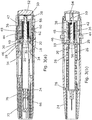
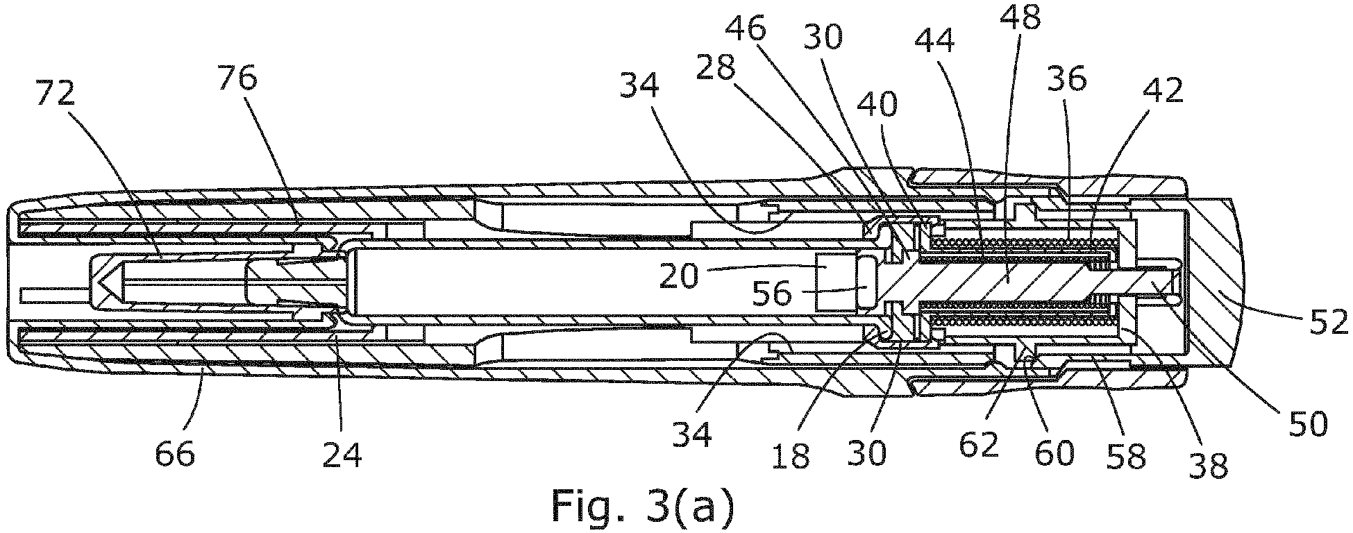
Figures 3(a) and (b) are respective side and top section views of the autoinjector with the cap in place, and removed; -
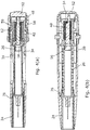
Figures 4(a) and(b) are respective side and top section views of the autoinjector with the firing button partially depressed immediately prior to the release of the plunger; -
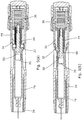
Figures 5(a), (b) and(c) are respective side section views showing the autoinjector with the syringe in its forwardmost position, shortly after breakout of the piston, and at the injection complete stage respectively; -
Figure 6 is a view of the device after use, with the shroud extended and locked out by the magnetically enabled latch; -
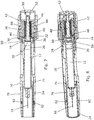
Figure 7 is a side view through a second embodiment of an autoinjector, and -
Figure 8 is a shaded side view. - Referring initially to
Figures 1 to 3 , the autoinjector comprises anouter housing 10 of cylindrical form in the bore of which is disposed asyringe 12 of known form with abarrel 14, aneedle 16 extending from the forward end, and aflange 18 at its rear end. A medicament is contained within the syringe and can be expressed through the needle by apiston 20 inside the barrel. The syringe is supported and surrounded by moulded plastics shroud/carrier 22 assembly comprising a forward hollowcylindrical portion 24 integrally formed with diametrically opposedsprings 26 to either side, and acollar 28 adapted to engage the forward face of the syringe flange. Extending rearwardly from the collar are two diametrically opposedclearance fingers 30 withbarbed teeth 32 that engage the intermediate member, as to be described below. In the pre-use position as shown inFigure 3(a) , the barbed fingers are prevented from outward splaying movement by the base of respective diametrically opposedgrooves 34 on the inner surface of the rear part of the housing. In the pre-use position, theshroud portion 24 is telescopically received within the forward end of the housing and co-terminous therewith. - In the rear of the housing is provided a drive mechanism which comprises a first
outer spring 36 which acts between the front face of a transverseinner wall 38 at the rear of the housing and aforward flange 40 of a top hat-shapedintermediate member 42. An inner, second,spring 44 is received within a cylindrical part of theintermediate member 42 and acts between an inner face of the rear end wall thereof and acircumferential rib 46 on the forward part of aplunger 48. At the rear end, the plunger has a resilient hooked arm 50 (seeFigures 1 ,3(b) ) which latches around the edge of an aperture in the transverseinner wall 38 of the housing. Projecting rearwardly from the rear end of the housing is a captive axiallyslideable trigger button 52 movable against a rearward bias from the position shown in e.g.Figure 3(b) , where arelease finger 54 is spaced rearwardly of the hookedarm 50, to a forward portion where thefinger 54 cams the hooked arm to release its retention by thewall 38, thereby allowing thesprings plunger 48 forwardly. The plunger is shaped and sized so that it can pass into and down the internal bore of thesyringe barrel 14, to urge thepiston 20 to express a dose. In the forward end of the plunger is a cylindrical recess in which is located a smallpowerful magnet 56. - The
trigger button 52 is biased rearwardly by means of two integral forwardly extending sprungarms 58 with cam surfaces 60 which ride overrespective abutments 62 inside the rear of the housing. However, initially, forward movement of the trigger button is prevented by means of two rearwardly extending lockingarms 64 which extend back from the rear end of acap 66. The cap covers the whole of the forward end of the housing and has a re-entrantcylindrical portion 68 with claw features 70. The claw features 70 slip over the rear end of aneedle shield 72 which is secured to the front end of the needle during manufacture. Thus thecap 66 fulfils the functions of acting as a safety catch for thetrigger button 52, serving as a shield remover. Anchored inside the forward end of the housing is alatch 74 formed of pressed steel or other ferro-magnetic material to provide twolatch arms 76 which extend forwardly from an anchorage normally to sit in an annular space between theshroud 24 and an inner part of the housing wall. - In operation, the user pulls the
cap 66 off forwardly which removes theneedle shield 72 from the syringe and arms the device by rendering thetrigger button 52 operational. The user then offers the injection device up to the injection site and presses thetrigger button 52. This releases the hookedarm 50 of theplunger 48 as shown more particularly inFigure 4(b) . Once the plunger is released, thefirst spring 36 expands to extend thesyringe 20 so that the needle penetrates the flesh. During this period (Figure 5(a) ), thesecond spring 44 remains substantially fully compressed, with theplunger 48 bearing against thepiston 20 within the syringe but not moving it relative to the syringe. During the initial phase of penetration, theclearance fingers 32 on thesyringe supporting collar 28 are constrained against outward splaying movement by thegrooves 34 and so a gap is preserved between thesyringe flange 18 and theflange 40 of theintermediate member 42, as long as the fingers are still in engagement with the constraining grooves. - The
fingers 32 exit the constraininggrooves 34 at about the same time as forward movement of the syringe is arrested by thecompression spring portions 26 bottoming out, theshroud 24 being held against movement by contact with the skin surface. When the syringe is arrested, thefirst spring 36 continues to expand to drive theflange 40 of the intermediate member into engagement with thesyringe flange 18 thereby contributing to the force required to initiate movement of the piston down the syringe (Figure 5(b) ). From this position thesecond spring 44 expands to drive the piston down the barrel of the syringe to express a dose. At the end of its travel, it will be noted that themagnet 56 in the plunger is spaced between the latchingarms 76 of thelatch 74, as shown inFigure 5(c) . When the dose has been expressed, the user pulls the device away from the flesh and so theshroud portion 24 is free to expand under the influence of thecompression spring portions 26. The shroud portion is driven by thesprings 26 forwardly beyond the front tips of the latchingarms 76. Once this happens, the latching arms are free to move inwardly to the latching positions shown inFigure 6 , under the influence of themagnet 20. Theshroud portion 24 is therefore locked out and the device thereby rendered safe. - In other embodiments, not shown, one or more further magnets or ferro-magnet material may be disposed in the front end of the housing around or in front of the syringe in order to provide a magnetic boost effect as the plunger nears the end of its stroke. It will also be appreciated that the exact position of the magnet(s) and interacting components can be varied.
- Referring now to
Figures 7 and 8 the second embodiment has many of the same components as the first embodiment and which act in a similar fashion. These components are given the same reference numbers and will not therefore be described in detail again. This second embodiment incorporates a magnetic coupling embodiment between theplunger 48 and the syringe designed so that during an initial penetration phase of movement the plunger is coupled magnetically to athrust collar 80 of ferro-magnetic material that is positioned in contact with the rear face of thesyringe flange 18. Thus theplunger 48 and thesyringe 18 are initially held against relative movement and so move as one during this phase, until the syringe is arrested by reaching its forwardmost position, with the needle inserted into the injection site. Upon arrest of the syringe, the spring force acting on the plunger overcomes the magnetic coupling force and the coupling yields so that the plunger is released to move forward relative to the syringe to move the plunger into contact with and to urge the piston forwardly to expel a dose. As previously, as the plunger moves alongside the ferro-magnetic latching arms 76 and they are attracted inwardly. This is enhanced in the embodiment by provision of twomagnets 82 on the forward ends of the latching arms. These magnets are aligned so as to be attached towards and to exert a pull on themagnet 56 in the plunger to provide a magnetically influenced forward boost to the plunger toward the forwardmost end of its stroke. Upon completion of the injection and removal of the device from the site, theshroud 24 extends forwardly as thespring portions 26 reexpand, and as a rearward lip on the shroud passes the magnets, the latching arms move inwards to block retraction movement of the shroud and thereby lock it out. Themagnets 82 may be housed slideably in through-holes in the housing wall, allowing them also to move inwards with the latching arms as the rearward lip on the shroud passes the magnets, and so provide a visual and tactile confirmation of locking out of theshroud 24.
Claims (6)
- An injection device comprising:an elongate housing (10);a removable cap (66);a syringe (12) disposed in said housing and having an internal piston (20) to express a dose from a needle (16) at its front end;a shroud element (24) movable forwardly relative to the syringe to shroud the needle after use; anda trigger button (52) biased rearwardly by means of two integral forwardly extending sprung arms (58), the arms having cam surfaces (60) which ride over respective abutments (62) inside the rear of the elongate housing (10) and whereinforward movement of the trigger button (52) is initially prevented by means of two rearwardly extending locking arms (64) which extend back from the rear end of a cap (66).
- The injection device of claim 1, whereinthe needle (16) has a needle shield (72) which is secured to the front end of the needle during manufacture; andthe user removes the cap (66) forwardly in use which removes the needle shield (22) from the syringe and arms the device by rendering the trigger button (52) operational.
- The injection device of claim 2, wherein the cap covers the whole of the forward end of the housing and comprises a re-entrant cylindrical portion (68) with claw features (70).
- The injection device of claim 3, wherein the claw features (70) slip over the rear end of a needle shield (72).
- The injection device of any preceding claim, wherein the trigger button projects rearwardly from the rear end of the housing and is captively axially slideable against a rearward bias.
- The injection device of claim 5, wherein the trigger button comprises a release finger (54) spaced rearwardly of a hooked arm (50) and is axially slideable to a forward position where the finger (54) cams the hooked arm (50) to release its retention by the wall (38), thereby allowing the springs (36, 44) to drive the plunger (48) forwardly.
Applications Claiming Priority (3)
| Application Number | Priority Date | Filing Date | Title |
|---|---|---|---|
| GBGB1017363.1A GB201017363D0 (en) | 2010-10-14 | 2010-10-14 | Injection devices |
| US39489610P | 2010-10-20 | 2010-10-20 | |
| EP11764253.8A EP2632517B1 (en) | 2010-10-14 | 2011-09-19 | Injection devices |
Related Parent Applications (2)
| Application Number | Title | Priority Date | Filing Date |
|---|---|---|---|
| EP11764253.8A Division-Into EP2632517B1 (en) | 2010-10-14 | 2011-09-19 | Injection devices |
| EP11764253.8A Division EP2632517B1 (en) | 2010-10-14 | 2011-09-19 | Injection devices |
Publications (1)
| Publication Number | Publication Date |
|---|---|
| EP3219348A1 true EP3219348A1 (en) | 2017-09-20 |
Family
ID=43304569
Family Applications (3)
| Application Number | Title | Priority Date | Filing Date |
|---|---|---|---|
| EP11764253.8A Not-in-force EP2632517B1 (en) | 2010-10-14 | 2011-09-19 | Injection devices |
| EP17162134.5A Withdrawn EP3219348A1 (en) | 2010-10-14 | 2011-09-19 | Injection devices |
| EP11776826.7A Revoked EP2632518B1 (en) | 2010-10-14 | 2011-10-11 | Injection devices |
Family Applications Before (1)
| Application Number | Title | Priority Date | Filing Date |
|---|---|---|---|
| EP11764253.8A Not-in-force EP2632517B1 (en) | 2010-10-14 | 2011-09-19 | Injection devices |
Family Applications After (1)
| Application Number | Title | Priority Date | Filing Date |
|---|---|---|---|
| EP11776826.7A Revoked EP2632518B1 (en) | 2010-10-14 | 2011-10-11 | Injection devices |
Country Status (5)
| Country | Link |
|---|---|
| US (2) | US9814840B2 (en) |
| EP (3) | EP2632517B1 (en) |
| JP (2) | JP6092779B2 (en) |
| GB (1) | GB201017363D0 (en) |
| WO (2) | WO2012049468A2 (en) |
Cited By (1)
| Publication number | Priority date | Publication date | Assignee | Title |
|---|---|---|---|---|
| CN110215570A (en) * | 2019-04-19 | 2019-09-10 | 吴银洪 | Full automatic solid sensor body inner injector with mutual exclusion tension stability |
Families Citing this family (40)
| Publication number | Priority date | Publication date | Assignee | Title |
|---|---|---|---|---|
| GB201017363D0 (en) | 2010-10-14 | 2010-11-24 | Owen Mumford Ltd | Injection devices |
| JP6178325B2 (en) | 2011-11-07 | 2017-08-09 | セーフティ シリンジズ, インコーポレイテッド | Contact trigger release needle guard |
| PL2908887T3 (en) * | 2012-10-19 | 2018-12-31 | Eli Lilly And Company | Automatic injection device with trigger assembly |
| AU2014241450A1 (en) | 2013-03-14 | 2015-08-06 | Eli Lilly And Company | Trigger assembly for an automatic injection device |
| AT514484B1 (en) * | 2013-06-24 | 2015-05-15 | Pharma Consult Gmbh | Activator for an auto-injector |
| GB2516624B (en) * | 2013-07-25 | 2018-09-19 | Owen Mumford Ltd | Injection devices |
| TWI569832B (en) * | 2013-10-23 | 2017-02-11 | 卡貝歐洲有限公司 | Drug delivery device |
| GB2530714A (en) | 2014-08-20 | 2016-04-06 | Owen Mumford Ltd | Injection devices |
| WO2016083370A1 (en) * | 2014-11-24 | 2016-06-02 | Sanofi | Drug delivery device with variable piston force |
| GB2541445B (en) | 2015-08-20 | 2018-04-18 | Owen Mumford Ltd | Injection device |
| GB2543274A (en) | 2015-10-12 | 2017-04-19 | Owen Mumford Ltd | Injection device |
| CN105498043A (en) * | 2016-01-15 | 2016-04-20 | 山东威高集团医用高分子制品股份有限公司 | Light-shielding syringe |
| USD819198S1 (en) | 2016-04-28 | 2018-05-29 | Amgen Inc. | Autoinjector with removable cap |
| US20180015224A1 (en) | 2016-07-13 | 2018-01-18 | California Institute Of Technology | Dampers and Methods for Performing Measurements in an Autoinjector |
| GB2560554A (en) | 2017-03-15 | 2018-09-19 | Owen Mumford Ltd | Injection device with gap reduction mechanism |
| GB2560557A (en) | 2017-03-15 | 2018-09-19 | Owen Mumford Ltd | Injection Device |
| EP3595750B1 (en) | 2017-03-15 | 2021-08-11 | Owen Mumford Limited | An injection apparatus |
| GB2560555A (en) | 2017-03-15 | 2018-09-19 | Owen Mumford Ltd | Injection device with deliver phase velocity regulator |
| WO2019175615A1 (en) * | 2018-03-14 | 2019-09-19 | Biocorp Production S.A. | Dose control device for injectable-drug delivery devices |
| EP3626288A1 (en) * | 2018-09-19 | 2020-03-25 | Tecpharma Licensing AG | Electronic add-on module for injectors |
| GB2577549B (en) * | 2018-09-28 | 2021-08-04 | Owen Mumford Ltd | Injection device with commit feature |
| TWI831847B (en) | 2018-11-01 | 2024-02-11 | 美商安進公司 | Drug delivery devices with partial needle retraction and methods for operating the same |
| MA54048A (en) | 2018-11-01 | 2022-02-09 | Amgen Inc | DRUG DELIVERY DEVICES WITH PARTIAL RETRACTION OF DRUG DELIVERY BODY |
| EP3873563A1 (en) | 2018-11-01 | 2021-09-08 | Amgen Inc. | Drug delivery devices with partial drug delivery member retraction |
| EP3930799B1 (en) * | 2019-02-26 | 2025-03-26 | Becton Dickinson France | Auto-injector with needle cover |
| EP3886946A1 (en) | 2019-06-05 | 2021-10-06 | Regeneron Pharmaceuticals, Inc. | Devices and methods for precision dose delivery |
| USD1010811S1 (en) | 2019-09-30 | 2024-01-09 | Amgen Inc. | Handheld drug delivery device |
| USD1030040S1 (en) | 2020-01-14 | 2024-06-04 | Amgen Inc. | Handheld drug delivery device |
| USD1030041S1 (en) | 2020-01-14 | 2024-06-04 | Amgen Inc. | Handheld drug delivery device |
| US11235105B2 (en) | 2020-03-20 | 2022-02-01 | Alexander Nikon | Auto-injector |
| BR112022026125A2 (en) * | 2020-06-23 | 2023-01-17 | Biocorp Production SA | INJECTION MONITORING MODULE |
| USD973866S1 (en) | 2020-11-05 | 2022-12-27 | Amgen Inc. | Handheld drug delivery device |
| USD974547S1 (en) | 2020-11-05 | 2023-01-03 | Amgen Inc. | Handheld drug delivery device |
| JP2021500643S (en) | 2020-11-05 | 2022-12-27 | Syringe | |
| USD985117S1 (en) | 2021-03-10 | 2023-05-02 | Amgen Inc. | Handheld drug delivery device |
| USD985118S1 (en) | 2021-03-10 | 2023-05-02 | Amgen Inc. | Handheld drug delivery device |
| USD985116S1 (en) | 2021-03-10 | 2023-05-02 | Amgen Inc. | Handheld drug delivery device |
| USD985119S1 (en) | 2021-03-30 | 2023-05-02 | Amgen Inc. | Handheld drug delivery device |
| USD1120314S1 (en) | 2022-11-30 | 2026-03-24 | Regeneron Pharmaceuticals, Inc. | Dose delivery device |
| WO2025247622A1 (en) * | 2024-05-27 | 2025-12-04 | Shl Medical Ag | Medicament delivery device |
Citations (2)
| Publication number | Priority date | Publication date | Assignee | Title |
|---|---|---|---|---|
| EP0518416A1 (en) * | 1991-06-13 | 1992-12-16 | Duphar International Research B.V | Injection device |
| WO2009063030A1 (en) * | 2007-11-14 | 2009-05-22 | Shl Group Ab | Automatic injection device with actively triggered syringe withdrawal |
Family Cites Families (50)
| Publication number | Priority date | Publication date | Assignee | Title |
|---|---|---|---|---|
| GB686343A (en) | 1950-09-26 | 1953-01-21 | Becton Dickinson Co | Improvements relating to hypodermic injection devices |
| BE755224A (en) | 1969-08-25 | 1971-02-24 | Philips Nv | INJECTION SYRINGE |
| US3712301A (en) * | 1971-01-11 | 1973-01-23 | Survival Technology | Gun type hypodermic injector with rapid cartridge displacement within holder |
| FR2348709A1 (en) * | 1976-04-23 | 1977-11-18 | Pistor Michel | MESOTHERAPIC TREATMENT PROCESS AND INJECTION DEVICE, FORMING AUTOMATIC MICRO-INJECTOR, INCLUDING APPLICATION |
| US5360410A (en) * | 1991-01-16 | 1994-11-01 | Senetek Plc | Safety syringe for mixing two-component medicaments |
| GB9200219D0 (en) | 1992-01-07 | 1992-02-26 | Medimech Int Ltd | Automatic injectors |
| US5599309A (en) | 1993-03-24 | 1997-02-04 | Owen Mumford Limited | Injection devices |
| US5709662A (en) | 1996-08-23 | 1998-01-20 | Becton Dickinson France, S.A. | Cartridge for an injection device |
| GB9714948D0 (en) | 1997-07-16 | 1997-09-17 | Owen Mumford Ltd | Improvements relating to injection devices |
| DE19731778A1 (en) * | 1997-07-24 | 1999-02-11 | Leon Helma Christina | Motor-driven automatic injection unit for human or veterinary use |
| US6616639B2 (en) * | 1998-04-17 | 2003-09-09 | Becton, Dickinson And Company | Safety shield system for syringes |
| WO2000015280A1 (en) | 1998-09-15 | 2000-03-23 | Njc Innovations | Devices with power-driven syringe for administering therapeutic substances |
| GB2342047A (en) | 1998-09-25 | 2000-04-05 | Charles Mcnairn | Single use syringe |
| JP2002119589A (en) * | 2000-10-18 | 2002-04-23 | Nipro Corp | Indwelling needle assembly |
| GB0119520D0 (en) | 2001-08-10 | 2001-10-03 | Owen Mumford Ltd | Improvements relating to injection devices |
| US6939323B2 (en) | 2001-10-26 | 2005-09-06 | Massachusetts Institute Of Technology | Needleless injector |
| US7517440B2 (en) * | 2002-07-17 | 2009-04-14 | Eksigent Technologies Llc | Electrokinetic delivery systems, devices and methods |
| JP2007518460A (en) * | 2003-05-09 | 2007-07-12 | イントラヴァック インコーポレーテッド | Needleless syringes and ampoules for intradermal, subcutaneous and intramuscular injection |
| GB0315600D0 (en) | 2003-07-04 | 2003-08-13 | Owen Mumford Ltd | Improvements relating to automatic injection devices |
| DE10342059B4 (en) | 2003-09-11 | 2007-03-01 | Tecpharma Licensing Ag | Delivery device with piercing and Ausschutinrichtung |
| US20050101919A1 (en) | 2003-11-07 | 2005-05-12 | Lennart Brunnberg | Device for an injector |
| CH696421A5 (en) | 2003-12-18 | 2007-06-15 | Tecpharma Licensing Ag | Autoinjector with arresting the drug container. |
| WO2006045215A1 (en) | 2004-10-27 | 2006-05-04 | Chang-Ming Yang | A safety seringe |
| BRPI0518833B8 (en) * | 2004-12-07 | 2021-06-22 | Becton Dickinson Co | arrangement and method of making a needle safe |
| US7833189B2 (en) | 2005-02-11 | 2010-11-16 | Massachusetts Institute Of Technology | Controlled needle-free transport |
| FR2884721A1 (en) | 2005-04-20 | 2006-10-27 | Becton Dickinson France Soc Pa | Assistance device for device of injection of a product, comprises hollow body for receiving the product, hollow injection needle for penetrating into injection site, piston placed in the body, hollow sleeve with bearing surface |
| DE202005010389U1 (en) | 2005-07-01 | 2005-09-08 | Tecpharma Licensing Ag | Injection unit capable of accommodating an ampule incorporates a fixed magnet and a counter-magnet on the movable piston rod of the unit |
| JP4983180B2 (en) * | 2005-09-20 | 2012-07-25 | パナソニック株式会社 | Injection device with puncture function, control method for injection device with puncture function, medicinal solution administration device, and control method for medicinal solution administration device |
| US8469924B2 (en) | 2006-04-04 | 2013-06-25 | Covidien Lp | Method and apparatus for generating vascular treatment foam |
| JP4973025B2 (en) * | 2006-06-26 | 2012-07-11 | ニプロ株式会社 | Safety needle assembly |
| US20080086089A1 (en) * | 2006-07-10 | 2008-04-10 | Isaacson S Ray | Magnetically induced safety technology |
| FR2905273B1 (en) | 2006-09-06 | 2009-04-03 | Becton Dickinson France Soc Pa | AUTOMATIC INJECTION DEVICE WITH TIMING MEANS. |
| WO2008064092A2 (en) | 2006-11-21 | 2008-05-29 | Intelliject, Inc. | Devices, systems and methods for medicament delivery |
| EP2129414A1 (en) | 2007-03-22 | 2009-12-09 | Tecpharma Licensing AG | Injection device having trigger safety devices |
| DK2162170T3 (en) * | 2007-07-06 | 2011-06-14 | Shl Group Ab | Single-shot syringe with double springs |
| ES2589322T3 (en) * | 2008-02-11 | 2016-11-11 | Safety Syringes, Inc. | Syringe with needle and clip safety guard to prevent the release of the protector during a reconstitution process |
| EP2990067B1 (en) | 2008-03-10 | 2019-09-04 | Antares Pharma, Inc. | Injector safety device |
| GB2460398A (en) * | 2008-05-20 | 2009-12-02 | Owen Mumford Ltd | Auto-injector having a magnetic injection indicator and a needle sheath retainer |
| WO2009158145A2 (en) | 2008-05-30 | 2009-12-30 | Allergan, Inc. | Injection device for soft-tissue augmentation fillers, bioactive agents and other biocompatible materials in liquid or gel form |
| JP2010000300A (en) * | 2008-06-23 | 2010-01-07 | Nipro Corp | Safety needle assembly |
| US8167844B2 (en) * | 2008-08-14 | 2012-05-01 | Protectus Medical Devices, Inc. | Safety IV needle/cannula introducer |
| GB0821492D0 (en) | 2008-11-25 | 2008-12-31 | Team Holdings Uk Ltd | Integrated auto-injector cartridge system |
| GB0823693D0 (en) | 2008-12-31 | 2009-02-04 | Owen Mumford Ltd | Autoinjector |
| GB0900930D0 (en) | 2009-01-20 | 2009-03-04 | Future Injection Technologies Ltd | Injection device |
| GB2467904B (en) | 2009-02-17 | 2013-06-12 | Oval Medical Technologies Ltd | Drug container and delivery mechanism |
| DK2255842T4 (en) * | 2009-05-26 | 2023-07-24 | Shl Medical Ag | Needle cap assembly |
| WO2011022559A1 (en) | 2009-08-19 | 2011-02-24 | Safety Syringes, Inc. | Patient-contact activated needle stick safety device |
| CA3081980C (en) * | 2009-10-16 | 2022-10-18 | Janssen Biotech, Inc. | Palm activated drug delivery device |
| US8915886B2 (en) | 2009-10-21 | 2014-12-23 | Owen Mumford Limited | Autoinjector |
| GB201017363D0 (en) | 2010-10-14 | 2010-11-24 | Owen Mumford Ltd | Injection devices |
-
2010
- 2010-10-14 GB GBGB1017363.1A patent/GB201017363D0/en not_active Ceased
-
2011
- 2011-09-19 WO PCT/GB2011/051754 patent/WO2012049468A2/en not_active Ceased
- 2011-09-19 US US13/878,479 patent/US9814840B2/en not_active Expired - Fee Related
- 2011-09-19 JP JP2013533277A patent/JP6092779B2/en not_active Expired - Fee Related
- 2011-09-19 EP EP11764253.8A patent/EP2632517B1/en not_active Not-in-force
- 2011-09-19 EP EP17162134.5A patent/EP3219348A1/en not_active Withdrawn
- 2011-10-11 EP EP11776826.7A patent/EP2632518B1/en not_active Revoked
- 2011-10-11 WO PCT/GB2011/051950 patent/WO2012049484A2/en not_active Ceased
- 2011-10-11 US US13/879,448 patent/US9579464B2/en not_active Expired - Fee Related
-
2016
- 2016-10-07 JP JP2016199412A patent/JP2017035517A/en not_active Ceased
Patent Citations (2)
| Publication number | Priority date | Publication date | Assignee | Title |
|---|---|---|---|---|
| EP0518416A1 (en) * | 1991-06-13 | 1992-12-16 | Duphar International Research B.V | Injection device |
| WO2009063030A1 (en) * | 2007-11-14 | 2009-05-22 | Shl Group Ab | Automatic injection device with actively triggered syringe withdrawal |
Cited By (1)
| Publication number | Priority date | Publication date | Assignee | Title |
|---|---|---|---|---|
| CN110215570A (en) * | 2019-04-19 | 2019-09-10 | 吴银洪 | Full automatic solid sensor body inner injector with mutual exclusion tension stability |
Also Published As
| Publication number | Publication date |
|---|---|
| GB201017363D0 (en) | 2010-11-24 |
| US20130197442A1 (en) | 2013-08-01 |
| JP2013540016A (en) | 2013-10-31 |
| US9579464B2 (en) | 2017-02-28 |
| WO2012049484A3 (en) | 2012-11-01 |
| EP2632517A2 (en) | 2013-09-04 |
| US9814840B2 (en) | 2017-11-14 |
| US20130281933A1 (en) | 2013-10-24 |
| WO2012049484A2 (en) | 2012-04-19 |
| EP2632518B1 (en) | 2016-06-22 |
| EP2632518A2 (en) | 2013-09-04 |
| JP6092779B2 (en) | 2017-03-08 |
| WO2012049468A3 (en) | 2012-07-05 |
| EP2632517B1 (en) | 2017-05-03 |
| WO2012049468A2 (en) | 2012-04-19 |
| JP2017035517A (en) | 2017-02-16 |
Similar Documents
| Publication | Publication Date | Title |
|---|---|---|
| EP2632517B1 (en) | Injection devices | |
| EP2490735B1 (en) | Autoinjector | |
| US8721593B2 (en) | Injection device | |
| AU2006310971B2 (en) | Autoinjector activation triggering element | |
| EP2175915B1 (en) | Injection device with locking mechanism for syringe carrier | |
| EP2175917A1 (en) | Injection device with locking mechanism for syringe carrier | |
| EP4173651A1 (en) | Autoinjector | |
| GB2553770A (en) | Injection device | |
| EP4387689A1 (en) | Autoinjector |
Legal Events
| Date | Code | Title | Description |
|---|---|---|---|
| PUAI | Public reference made under article 153(3) epc to a published international application that has entered the european phase |
Free format text: ORIGINAL CODE: 0009012 |
|
| STAA | Information on the status of an ep patent application or granted ep patent |
Free format text: STATUS: THE APPLICATION HAS BEEN PUBLISHED |
|
| AC | Divisional application: reference to earlier application |
Ref document number: 2632517 Country of ref document: EP Kind code of ref document: P |
|
| AK | Designated contracting states |
Kind code of ref document: A1 Designated state(s): AL AT BE BG CH CY CZ DE DK EE ES FI FR GB GR HR HU IE IS IT LI LT LU LV MC MK MT NL NO PL PT RO RS SE SI SK SM TR |
|
| STAA | Information on the status of an ep patent application or granted ep patent |
Free format text: STATUS: REQUEST FOR EXAMINATION WAS MADE |
|
| 17P | Request for examination filed |
Effective date: 20180320 |
|
| RBV | Designated contracting states (corrected) |
Designated state(s): AL AT BE BG CH CY CZ DE DK EE ES FI FR GB GR HR HU IE IS IT LI LT LU LV MC MK MT NL NO PL PT RO RS SE SI SK SM TR |
|
| GRAP | Despatch of communication of intention to grant a patent |
Free format text: ORIGINAL CODE: EPIDOSNIGR1 |
|
| STAA | Information on the status of an ep patent application or granted ep patent |
Free format text: STATUS: GRANT OF PATENT IS INTENDED |
|
| RIC1 | Information provided on ipc code assigned before grant |
Ipc: A61M 5/20 20060101ALI20180608BHEP Ipc: A61M 5/32 20060101ALN20180608BHEP Ipc: A61M 5/50 20060101AFI20180608BHEP Ipc: A61M 5/315 20060101ALI20180608BHEP |
|
| INTG | Intention to grant announced |
Effective date: 20180717 |
|
| RAP1 | Party data changed (applicant data changed or rights of an application transferred) |
Owner name: OWEN MUMFORD LIMITED |
|
| STAA | Information on the status of an ep patent application or granted ep patent |
Free format text: STATUS: THE APPLICATION IS DEEMED TO BE WITHDRAWN |
|
| 18D | Application deemed to be withdrawn |
Effective date: 20181128 |