EP3219331B1 - Containing device for a treatment machine, in particular a washing and/or sterilization machine, for loose products - Google Patents
Containing device for a treatment machine, in particular a washing and/or sterilization machine, for loose products Download PDFInfo
- Publication number
- EP3219331B1 EP3219331B1 EP17160913.4A EP17160913A EP3219331B1 EP 3219331 B1 EP3219331 B1 EP 3219331B1 EP 17160913 A EP17160913 A EP 17160913A EP 3219331 B1 EP3219331 B1 EP 3219331B1
- Authority
- EP
- European Patent Office
- Prior art keywords
- loose products
- unloading
- loading
- treated
- door
- Prior art date
- Legal status (The legal status is an assumption and is not a legal conclusion. Google has not performed a legal analysis and makes no representation as to the accuracy of the status listed.)
- Active
Links
- 230000001954 sterilising effect Effects 0.000 title claims description 13
- 238000005406 washing Methods 0.000 title claims description 13
- 238000004659 sterilization and disinfection Methods 0.000 title description 9
- 238000000034 method Methods 0.000 claims description 9
- 238000009825 accumulation Methods 0.000 description 3
- 229940079593 drug Drugs 0.000 description 3
- 239000003814 drug Substances 0.000 description 3
- 238000004458 analytical method Methods 0.000 description 2
- 230000001419 dependent effect Effects 0.000 description 2
- 230000005484 gravity Effects 0.000 description 2
- 238000012986 modification Methods 0.000 description 2
- 230000004048 modification Effects 0.000 description 2
- 239000000126 substance Substances 0.000 description 2
- 238000007792 addition Methods 0.000 description 1
- 230000005540 biological transmission Effects 0.000 description 1
- 238000005352 clarification Methods 0.000 description 1
- 238000010276 construction Methods 0.000 description 1
- 238000005516 engineering process Methods 0.000 description 1
- 238000003780 insertion Methods 0.000 description 1
- 230000037431 insertion Effects 0.000 description 1
- 238000004519 manufacturing process Methods 0.000 description 1
- 239000000463 material Substances 0.000 description 1
- 229910052751 metal Inorganic materials 0.000 description 1
- 239000002184 metal Substances 0.000 description 1
- 229910001092 metal group alloy Inorganic materials 0.000 description 1
- 150000002739 metals Chemical class 0.000 description 1
- 239000004033 plastic Substances 0.000 description 1
- 239000002861 polymer material Substances 0.000 description 1
- 239000005060 rubber Substances 0.000 description 1
Images


Classifications
-
- B—PERFORMING OPERATIONS; TRANSPORTING
- B08—CLEANING
- B08B—CLEANING IN GENERAL; PREVENTION OF FOULING IN GENERAL
- B08B3/00—Cleaning by methods involving the use or presence of liquid or steam
- B08B3/04—Cleaning involving contact with liquid
- B08B3/045—Cleaning involving contact with liquid using perforated containers, e.g. baskets, or racks immersed and agitated in a liquid bath
-
- B—PERFORMING OPERATIONS; TRANSPORTING
- B65—CONVEYING; PACKING; STORING; HANDLING THIN OR FILAMENTARY MATERIAL
- B65G—TRANSPORT OR STORAGE DEVICES, e.g. CONVEYORS FOR LOADING OR TIPPING, SHOP CONVEYOR SYSTEMS OR PNEUMATIC TUBE CONVEYORS
- B65G65/00—Loading or unloading
- B65G65/30—Methods or devices for filling or emptying bunkers, hoppers, tanks, or like containers, of interest apart from their use in particular chemical or physical processes or their application in particular machines, e.g. not covered by a single other subclass
- B65G65/34—Emptying devices
- B65G65/40—Devices for emptying otherwise than from the top
-
- A—HUMAN NECESSITIES
- A61—MEDICAL OR VETERINARY SCIENCE; HYGIENE
- A61L—METHODS OR APPARATUS FOR STERILISING MATERIALS OR OBJECTS IN GENERAL; DISINFECTION, STERILISATION OR DEODORISATION OF AIR; CHEMICAL ASPECTS OF BANDAGES, DRESSINGS, ABSORBENT PADS OR SURGICAL ARTICLES; MATERIALS FOR BANDAGES, DRESSINGS, ABSORBENT PADS OR SURGICAL ARTICLES
- A61L2/00—Methods or apparatus for disinfecting or sterilising materials or objects other than foodstuffs or contact lenses; Accessories therefor
- A61L2/26—Accessories or devices or components used for biocidal treatment
-
- B—PERFORMING OPERATIONS; TRANSPORTING
- B08—CLEANING
- B08B—CLEANING IN GENERAL; PREVENTION OF FOULING IN GENERAL
- B08B3/00—Cleaning by methods involving the use or presence of liquid or steam
- B08B3/04—Cleaning involving contact with liquid
- B08B3/045—Cleaning involving contact with liquid using perforated containers, e.g. baskets, or racks immersed and agitated in a liquid bath
- B08B3/047—Containers specially adapted therefor
-
- B—PERFORMING OPERATIONS; TRANSPORTING
- B08—CLEANING
- B08B—CLEANING IN GENERAL; PREVENTION OF FOULING IN GENERAL
- B08B3/00—Cleaning by methods involving the use or presence of liquid or steam
- B08B3/04—Cleaning involving contact with liquid
- B08B3/06—Cleaning involving contact with liquid using perforated drums in which the article or material is placed
-
- B—PERFORMING OPERATIONS; TRANSPORTING
- B65—CONVEYING; PACKING; STORING; HANDLING THIN OR FILAMENTARY MATERIAL
- B65B—MACHINES, APPARATUS OR DEVICES FOR, OR METHODS OF, PACKAGING ARTICLES OR MATERIALS; UNPACKING
- B65B55/00—Preserving, protecting or purifying packages or package contents in association with packaging
- B65B55/02—Sterilising, e.g. of complete packages
- B65B55/12—Sterilising contents prior to, or during, packaging
-
- B—PERFORMING OPERATIONS; TRANSPORTING
- B65—CONVEYING; PACKING; STORING; HANDLING THIN OR FILAMENTARY MATERIAL
- B65D—CONTAINERS FOR STORAGE OR TRANSPORT OF ARTICLES OR MATERIALS, e.g. BAGS, BARRELS, BOTTLES, BOXES, CANS, CARTONS, CRATES, DRUMS, JARS, TANKS, HOPPERS, FORWARDING CONTAINERS; ACCESSORIES, CLOSURES, OR FITTINGS THEREFOR; PACKAGING ELEMENTS; PACKAGES
- B65D43/00—Lids or covers for rigid or semi-rigid containers
- B65D43/14—Non-removable lids or covers
- B65D43/16—Non-removable lids or covers hinged for upward or downward movement
- B65D43/161—Non-removable lids or covers hinged for upward or downward movement comprising two or more cover sections hinged one to another
-
- B—PERFORMING OPERATIONS; TRANSPORTING
- B65—CONVEYING; PACKING; STORING; HANDLING THIN OR FILAMENTARY MATERIAL
- B65D—CONTAINERS FOR STORAGE OR TRANSPORT OF ARTICLES OR MATERIALS, e.g. BAGS, BARRELS, BOTTLES, BOXES, CANS, CARTONS, CRATES, DRUMS, JARS, TANKS, HOPPERS, FORWARDING CONTAINERS; ACCESSORIES, CLOSURES, OR FITTINGS THEREFOR; PACKAGING ELEMENTS; PACKAGES
- B65D7/00—Containers having bodies formed by interconnecting or uniting two or more rigid, or substantially rigid, components made wholly or mainly of metal
- B65D7/12—Containers having bodies formed by interconnecting or uniting two or more rigid, or substantially rigid, components made wholly or mainly of metal characterised by wall construction or by connections between walls
- B65D7/14—Containers having bodies formed by interconnecting or uniting two or more rigid, or substantially rigid, components made wholly or mainly of metal characterised by wall construction or by connections between walls of skeleton or like apertured construction, e.g. baskets or carriers formed of wire mesh, of interconnected bands, bars, or rods, or of perforated sheet metal
- B65D7/16—Containers having bodies formed by interconnecting or uniting two or more rigid, or substantially rigid, components made wholly or mainly of metal characterised by wall construction or by connections between walls of skeleton or like apertured construction, e.g. baskets or carriers formed of wire mesh, of interconnected bands, bars, or rods, or of perforated sheet metal made of apertured or perforated sheet metal components
-
- B—PERFORMING OPERATIONS; TRANSPORTING
- B65—CONVEYING; PACKING; STORING; HANDLING THIN OR FILAMENTARY MATERIAL
- B65G—TRANSPORT OR STORAGE DEVICES, e.g. CONVEYORS FOR LOADING OR TIPPING, SHOP CONVEYOR SYSTEMS OR PNEUMATIC TUBE CONVEYORS
- B65G65/00—Loading or unloading
- B65G65/30—Methods or devices for filling or emptying bunkers, hoppers, tanks, or like containers, of interest apart from their use in particular chemical or physical processes or their application in particular machines, e.g. not covered by a single other subclass
- B65G65/32—Filling devices
-
- D—TEXTILES; PAPER
- D06—TREATMENT OF TEXTILES OR THE LIKE; LAUNDERING; FLEXIBLE MATERIALS NOT OTHERWISE PROVIDED FOR
- D06F—LAUNDERING, DRYING, IRONING, PRESSING OR FOLDING TEXTILE ARTICLES
- D06F21/00—Washing machines with receptacles, e.g. perforated, having a rotary movement, e.g. oscillatory movement
- D06F21/02—Washing machines with receptacles, e.g. perforated, having a rotary movement, e.g. oscillatory movement about a horizontal axis
- D06F21/04—Washing machines with receptacles, e.g. perforated, having a rotary movement, e.g. oscillatory movement about a horizontal axis within an enclosing receptacle
-
- A—HUMAN NECESSITIES
- A61—MEDICAL OR VETERINARY SCIENCE; HYGIENE
- A61L—METHODS OR APPARATUS FOR STERILISING MATERIALS OR OBJECTS IN GENERAL; DISINFECTION, STERILISATION OR DEODORISATION OF AIR; CHEMICAL ASPECTS OF BANDAGES, DRESSINGS, ABSORBENT PADS OR SURGICAL ARTICLES; MATERIALS FOR BANDAGES, DRESSINGS, ABSORBENT PADS OR SURGICAL ARTICLES
- A61L2/00—Methods or apparatus for disinfecting or sterilising materials or objects other than foodstuffs or contact lenses; Accessories therefor
- A61L2/16—Methods or apparatus for disinfecting or sterilising materials or objects other than foodstuffs or contact lenses; Accessories therefor using chemical substances
- A61L2/18—Liquid substances or solutions comprising solids or dissolved gases
-
- A—HUMAN NECESSITIES
- A61—MEDICAL OR VETERINARY SCIENCE; HYGIENE
- A61L—METHODS OR APPARATUS FOR STERILISING MATERIALS OR OBJECTS IN GENERAL; DISINFECTION, STERILISATION OR DEODORISATION OF AIR; CHEMICAL ASPECTS OF BANDAGES, DRESSINGS, ABSORBENT PADS OR SURGICAL ARTICLES; MATERIALS FOR BANDAGES, DRESSINGS, ABSORBENT PADS OR SURGICAL ARTICLES
- A61L2/00—Methods or apparatus for disinfecting or sterilising materials or objects other than foodstuffs or contact lenses; Accessories therefor
- A61L2/16—Methods or apparatus for disinfecting or sterilising materials or objects other than foodstuffs or contact lenses; Accessories therefor using chemical substances
- A61L2/20—Gaseous substances, e.g. vapours
-
- A—HUMAN NECESSITIES
- A61—MEDICAL OR VETERINARY SCIENCE; HYGIENE
- A61L—METHODS OR APPARATUS FOR STERILISING MATERIALS OR OBJECTS IN GENERAL; DISINFECTION, STERILISATION OR DEODORISATION OF AIR; CHEMICAL ASPECTS OF BANDAGES, DRESSINGS, ABSORBENT PADS OR SURGICAL ARTICLES; MATERIALS FOR BANDAGES, DRESSINGS, ABSORBENT PADS OR SURGICAL ARTICLES
- A61L2202/00—Aspects relating to methods or apparatus for disinfecting or sterilising materials or objects
- A61L2202/10—Apparatus features
- A61L2202/12—Apparatus for isolating biocidal substances from the environment
- A61L2202/122—Chambers for sterilisation
-
- A—HUMAN NECESSITIES
- A61—MEDICAL OR VETERINARY SCIENCE; HYGIENE
- A61L—METHODS OR APPARATUS FOR STERILISING MATERIALS OR OBJECTS IN GENERAL; DISINFECTION, STERILISATION OR DEODORISATION OF AIR; CHEMICAL ASPECTS OF BANDAGES, DRESSINGS, ABSORBENT PADS OR SURGICAL ARTICLES; MATERIALS FOR BANDAGES, DRESSINGS, ABSORBENT PADS OR SURGICAL ARTICLES
- A61L2202/00—Aspects relating to methods or apparatus for disinfecting or sterilising materials or objects
- A61L2202/10—Apparatus features
- A61L2202/17—Combination with washing or cleaning means
Definitions
- the present invention concerns a containing device for loose products suitable for a machine for treating them, for example washing and/or sterilizing them, and usable for example in the pharmaceutical field, hospitals, the food industry or in the industrial field, in the production of loose products.
- the loose products can be, for example, closing stoppers for test tubes for laboratory analysis, closing stoppers for phials of medicines, or small instruments or objects used in operating theaters or laboratories.
- the present invention also concerns a treatment method and machine, for example washing and/or sterilization, for loose products, in which, in particular, the zones where the loose products are loaded and unloaded are positioned on the same side.
- the rotary drums of these machines are partitioned by a multitude of containing devices, such as for example angular containing sectors, each able to contain, with every operating cycle, a desired quantity of loose products to be treated.
- the containing devices are normally in the form of racks, so as to guarantee an efficient washing and/or sterilization treatment.
- stoppers for closing test tubes intended to contain substances to be subjected to laboratory analysis
- closing stoppers for phials of medicines or generally for containers of medicines, or small instruments or objects used in operating theaters or laboratories The materials they can be made of include, by way of example, rubber, plastic, polymer materials, metals or metal alloys.
- the loose products to be treated are loaded, through a first aperture provided with a door and manually or automatically inside the containing devices in order to carry out the treatment, for example washing and/or sterilization. Once the loose products have finished their treatment, they are unloaded through a second aperture, communicating for example with an unloading valve.
- machines for treating loose products which have the first loading aperture for the loose products to be treated and the second aperture for unloading the treated products on the same side; these machines are therefore very compact, efficient and particularly suitable for use in spaces that have to be limited.
- the accumulation of loose products can occur for example in the bottom of the containing devices which, as we said, can be in the shape of angular sectors.
- Document EP 2275018 A2 describes a machine for treating loose products, in particular for washing them, provided with a device to contain the loose products.
- one purpose of the present invention is to obtain a containing device for loose products, particularly suitable for machines for treating loose products with the loading and unloading of the loose products on the same side, which prevents any risk of blockage and/or accumulation of loose products both in the loading step and also in the unloading step.
- Another purpose of the present invention is to obtain a containing device for loose products which, in the unloading of the loose products that have been treated, has an unloading area which is totally without any obstacle, therefore by means of which the loose products can be conveyed due to gravity, rapidly and efficiently toward an unloading zone of the machine.
- Another purpose of the present invention is to obtain a containing device for loose products which prevents the loose products from escaping accidentally and unwantedly during any step of their treatment inside the drum.
- Another purpose of the present invention is to obtain a treatment machine for loose products provided with loading and unloading zones of the loose products situated on the same side, which allows rapid and efficient operations to load and unload the loose products.
- the Applicant has devised, tested and embodied the present invention to overcome the shortcomings of the state of the art and to obtain these and other purposes and advantages.
- a containing device suitable to house loose products, is provided internally with a treatment compartment that has two flat and opposite lateral walls, connected by two other lateral walls; wherein said two flat and opposite lateral walls and said two other lateral walls are connected in correspondence with their lower sides by means of a bottom wall and form on their upper sides at least one open side to load the loose products to be treated and to unload the loose products that have been treated; and wherein the planes on which said two flat and opposite lateral walls lie are reciprocally symmetrical with respect to a plane, so that said planes converge on a line positioned on the other side of the bottom wall with respect to the open side; whereby the containing device comprises at least a first loading door for the loose products to be treated, positioned on a first portion of said open side and associated with at least a respective opening and closing unit, and at least a second unloading door for the loose products that have been treated, positioned on a second portion of said open side and associated with at least a respective opening and closing unit
- the loading door and the unloading door are connected to the containing device by means of corresponding rotation pins that allow said doors to rotate around said rotation pins, whereby said rotation pins are situated nearer to each other than to any of said flat and opposite lateral walls.
- the present invention also concerns a machine to treat loose products, comprising a treatment chamber in which a rotatable drum is housed, a loading zone for loading the loose products to be treated and an unloading zone for unloading the loose products that have been treated, positioned on the same side of the machine, in which the drum comprises a plurality of containing devices as defined above.
- the invention also concerns a method for treating loose products in a treatment machine for loose products, where the machine comprises a treatment chamber in which a rotatable drum is housed, a loading zone for loading the loose products to be treated and an unloading zone for unloading the loose products that have been treated, positioned on the same side of the machine, the drum comprises a plurality of containing devices as defined above and provided internally with a treatment compartment that has at least one open side for loading the loose products to be treated and for unloading the loose products that have been treated.
- the method comprises loading the loose products to be treated in said treatment compartment of each of the containing devices through a loading door positioned on a first portion of the open side of the treatment compartment of each of the containing devices, treating said loose products by rotating the drum, and unloading the loose products that have been treated from each of said containing devices by means of an unloading door positioned on a second portion of said open side of the treatment compartment of each of the containing devices.
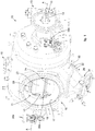
- a machine 10 for treating loose products for example washing and/or sterilizing loose products, comprises a treatment chamber 11 inside which a rotatable drum 12 is housed.
- the drum 12 can be made to rotate around an axis A by means of a drive device 13 which, through a transmission unit 15, makes a shaft 14 rotate which is suitably integrated with the drum 12.
- the axis of rotation A is preferably the longitudinal axis of the machine.
- the drum 12 (see fig. 5 for example) is provided with a plurality of containing devices 20 for the loose products to be treated.
- the machine 10 (see fig. 1 and 2 for example), comprises a first loading zone 16 of the loose products, in particular a manual loading zone, provided with a loading aperture 17 associated with a loading door 18, able to allow the manual loading of the loose products inside the drum 12.
- the machine 10 also comprises a second loading zone 19 of the loose products, in particular an automatic loading zone, in which a pneumatic loading apparatus can be provided for example, for loading the loose products into the drum 12.
- the machine 10 comprises an unloading zone 29 of the loose products that have been treated inside the containing devices 20 of the drum 12.
- the unloading zone 29 comprises an unloading pipe 30, situated in a lower part of the treatment chamber 11.
- the unloading pipe 30 faces at a first end toward the containing devices 20 of the drum 12, and is connected, at the opposite end, with an unloading valve 31.
- the connection between the unloading pipe 30 and the unloading valve 31 can be obtained for example by means of a pair of flanges 32.
- the loading zone 16 of the loose products to be treated and the unloading zone 29 of the loose products that have been treated are positioned on the same side of the machine, for example the front side.
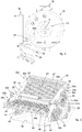
- the containing devices 20 are in the form of a rack and each comprise a treatment compartment 40 in which the loose products to be treated are introduced.
- the treatment compartment 40 is delimited by a bottom wall 21 facing toward the center of the drum 12, hence toward the axis of rotation A of the drum 12.
- Each of the containing devices 20 also comprises an open side 22, opposite the bottom wall 21, on which an unloading door 23 is disposed, positioned on a first portion of the open side 22 and suitable to allow the loose products to be treated to be loaded, and also an unloading door 24, positioned on a second portion of the open side 22 and suitable to allow the loose products that have been treated to be unloaded from the containing device 20.
- the loading door 23 is rotatable around a first rotation pin 25, while the unloading door 24 is rotatable around a second rotation pin 26.
- the first rotation pin 25 and the second rotation pin 26 are positioned in correspondence with a central zone of the open side 22 of the containing device 20.
- the loading and unloading doors 23 and 24 can be made of the same size and be disposed specular with respect to a symmetry plane P, in particular a longitudinal plane, of the containing device 20.
- the loading and unloading doors 23 and 24 are able to rotate, to open or close, in opposite directions around the corresponding rotation pins 25 and 26.
- the treatment compartment 40 of each of the containing devices 20 is completed by first lateral walls 27 and 28, that is to say, an upper wall 27 and a lower wall 28, directed in a longitudinal direction of the machine 10 and the drum 12, hence a direction substantially parallel to the axis A, and by two other lateral walls 41 and 42, positioned in a direction substantially transverse to the axis A.
- the upper wall 27 and the lower wall 28, that is, the first lateral walls, are substantially flat and opposite the plane P.
- the walls 27 and 28 lie on planes P1 and P2 which converge, together with the plane P, on a determinate line D (see fig. 5 in particular).
- the planes P1 and P2 are symmetrical with respect to the plane P.
- Line D is situated near axis A and could coincide with axis A. Moreover, the line D could be common to all the containing devices 20.
- the rotation pins 25 and 26 are nearer each other that to any of the lateral walls 27 and 28.
- the containing devices 20 are in the form of a rack, therefore at least some of the walls described above and which define the treatment compartment 40 are wholly or partly provided with small holes or suchlike, so that in the containing device 20 the washing and/or sterilization treatment can be efficiently carried out.
- the loading and unloading doors 23 and 24 can also be provided wholly or partly with small holes.
- the bottom wall 21 is smaller in extension than the open side 22, so that the containing devices 20 have a substantially trapezoid shape of the cross section.
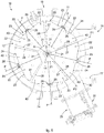
- the containing devices 20 can be made as sectors of a circle with the center in the axis A and preferably positioned so that they are adjacent to each other or suitably distanced from each other.
- the containing devices 20 are identical to each other and are positioned at regular intervals around the axis of rotation A of the rotary drum 12.
- the drum 12 can comprise any number whatsoever of containing devices 20, however Applicant has found that a particularly effective and productive conformation comprises the disposition of five containing devices 20, as in fig. 5 , which confer on the drum 12 in its entirety a substantially pentagonal shape.
- Each of the loading and unloading doors 23 and 24 of each of the containing devices 20 is associated, on both the opposite lateral walls 41 and 42, with a respective opening and closing unit 33a and 33b.
- Each pair of opening and closing units 33a is connected to a respective loading door 23, so as to make it selectively assume an open or closed position.
- Each pair of opening and closing units 33b is connected to a respective unloading door 24, so as to make it selectively assume an open or closed position.
- the loading door 23, in its closed position, is able to abut on pins 43 protruding from the lateral walls 41 and 42, while the unloading door 24, in its closed position, is able to abut on other pins 44 protruding from the lateral walls 41 and 42.
- Each opening and closing unit 33a of the loading door 23 comprises a first arm 34a carrying an end part 35a cooperating with the loading door 23, preferably in a zone near the free edge 47 of the loading door 23, that is to say, the edge opposite the rotation pin 25.
- the first arm 34a of each of the opening and closing units 33a is connected, by means of an articulation pin 36a, to one end of a second arm 37a, the other end of which is rotatably connected to the rotation pin 25.
- Each opening and closing unit 33b of the unloading door 24 comprises a first arm 34b carrying an end part 35b associated with the unloading door 24, preferably in a zone near the free edge 46 of the unloading door 24, that is to say, the edge opposite the rotation pin 26.
- the first arm 34b of the opening and closing unit 33b is connected, by means of an articulation pin 36b, to one end of a second arm 37b, the other end of which is rotatably connected to the rotation pin 26.
- the positioning is provided of at least one pawl 45b, protruding laterally from at least one of said opening and closing units 33b.
- the pawl 45b is positioned in correspondence with the articulation pin 36b. In the case of fig. 3 , the pawl 45b protrudes from the opening and closing unit 33b of the unloading door 24 situated on the right, looking at the drawing.
- the positioning is provided of at least one pawl 45a (see fig. 6 ), protruding laterally from at least one of said opening and closing units 33a.
- the pawl 45a is positioned in correspondence with the articulation pin 36a.
- the loading and unloading doors 23 and 24 can be opened by thrusting on the corresponding pawls 45a and 45b of the corresponding opening and closing units 33a and 33b, against the possible action of elastic return elements that tend to keep the loading and unloading doors 23 and 24 in the closed position.
- the opening and closing units 33a of the loading doors 23 cooperate, by means of the corresponding pawls 45a, with an actuator 38a comprising a drive element 39a, for example a cam type drive element, which on each occasion can engage with the pawl 45a of an opening and closing unit 33a of the loading door 23 to allow to load the loose products to be treated inside the containing device 20.
- a drive element 39a for example a cam type drive element
- the opening and closing units 33b of the unloading doors 24 cooperate, by means of the corresponding pawls 45b, with an actuator 38b comprising a drive element 39b, for example a cam type drive element, which on each occasion can engage with the pawl 45b of the unloading door 24 to allow to unload the loose products that have been treated from the containing device 20.
- a drive element 39b for example a cam type drive element
- the actuators 38a and 38b are preferably positioned on opposite sides of the machine 10 and the drum 12 (see fig. 1 or fig. 4 for example).
- the pawls 45a associated with the opening and closing units 33a of the loading doors 23 and the pawls 45b associated with the opening and closing units 33b of the unloading doors 24 are also situated on opposite sides of the containing device 20 and the drum 12.
- the drive element 39a of the actuator 38a engages on each occasion with a pawl 45a protruding from the opening and closing unit 33a of the loading door 23.
- the drive element 39b of the actuator 38b following the rotation of the drum 12, also engages on each occasion with a pawl 45b protruding from the opening and closing unit 33b of the unloading door 24.
- Fig. 6 shows a loading door 23 open in correspondence with the loading zone 16 thanks to the rotation and thrust of the drive element 39a of the actuator 38a on the pawl 45a.
- the thrust of the drive element 39a on the pawl 45a determines a rotation of the arms 34a and 37a around the rotation pin 25. In this step it is possible to introduce the loose products to be treated manually inside the containing device 20, through the loading zone 16, and then to close the loading door 23.
- the loading door 23 and the upper wall 27 of the containing device 20 are in a position divergent toward the loading zone 16, so as to facilitate, like a sort of funnel, the insertion of the loose products inside the containing device 20.
- the containing device 20 When the planned quantity of loose products to be treated has been introduced into the containing device 20 with the loading door 23 open, the containing device 20 is closed by lowering the loading door 23 and the drum 12 is made to rotate, for example in a clockwise direction (see fig. 7 ), so that a new, empty containing device 20 is presented in correspondence with the loading zone 16.
- the drive element 39a of the actuator 38a will therefore engage the pawl 45a of a subsequent containing device 20, to open its loading door 23.
- the treatment process can begin, operated by the machine 10 by rotating the drum 12, for example washing and/or sterilization.
- Fig. 7 and fig. 3 show an unloading door 24 open in correspondence with the unloading zone 29, thanks to the rotation and thrust of the drive element 39b of the actuator 38b on the pawl 45b.
- the thrust of the drive element 39b on the pawl 45b determines a rotation of the arms 34b and 37b around the rotation pin 26. In this step it is therefore possible to unload the loose products that have been treated, through the unloading zone 29, from inside the containing device 20 and then to close the unloading door 24 again.
- the unloading door 24 shown in the open position in fig. 7 therefore has a big unloading zone for the loose products to the unloading pipe 30.
- the unloading door 24 and the lower wall 28 of the containing device 20 along which the treated loose products slide are divergent toward the unloading zone 29, therefore the loose products that have been treated do not meet any obstacle and descend rapidly and due to gravity toward the unloading zone 29.
- the drum 12 is rotated to present all the containing devices 20 in succession in correspondence with the actuator 38b, so that the respective drive element 39b can engage with the pawls 45b of the opening and closing units 33b of said containing devices 20, so that all the containing devices 20 can be emptied.
- the unloading door 24 in the open position is also visible in the three-dimensional view of fig. 1 and in the lateral view of fig. 2 .
- the present containing device 20 By means of the present containing device 20, it is therefore possible to guarantee effective loading operations of loose products to be treated and unloading operations of loose products that have been treated from the drum 12 by means of a loading door 23 and an unloading door 24 that are positioned on the open side 22 of the containing device 20 and are selectively opened or closed to allow the loading of the loose products to be treated and the unloading of the loose products that have been treated.
- the loading door 23, once open, and the lateral wall of the containing device 20 nearest the loading zone 16, that is, the upper wall 27, have a suitable divergence toward the loading zone 16 so as to facilitate, like a sort of funnel, the loading of the loose products to be treated into the containing device 20.
- the unloading door 24, once open, and the lateral wall of the containing device 20 nearest the unloading zone 29, that is, the lower wall 28, have a suitable divergence toward the unloading zone 29 so as to facilitate the unloading of the loose products that have been treated from the containing device 20.
- the containing device 20 with loading and unloading doors 23 and 24 is particularly suitable for use in a machine 10 for treating loose products with a loading zone 16 and an unloading zone 29 situated on the same side of the machine.
Description
- The present invention concerns a containing device for loose products suitable for a machine for treating them, for example washing and/or sterilizing them, and usable for example in the pharmaceutical field, hospitals, the food industry or in the industrial field, in the production of loose products.
- The loose products can be, for example, closing stoppers for test tubes for laboratory analysis, closing stoppers for phials of medicines, or small instruments or objects used in operating theaters or laboratories.
- The present invention also concerns a treatment method and machine, for example washing and/or sterilization, for loose products, in which, in particular, the zones where the loose products are loaded and unloaded are positioned on the same side.
- It is known, in the pharmaceutical field, in hospitals or other fields, for example the food industry, that it is necessary to treat, for example wash and/or sterilize, loose products in washing and/or sterilization machines provided with a sealed treatment chamber, delimited by walls, in which a rotary drum receives the loose products to be treated on a loading side, washes and/or sterilizes them during a treatment cycle, and unloads them on an unloading side, where they are generally packaged in sterile packages.
- The rotary drums of these machines are partitioned by a multitude of containing devices, such as for example angular containing sectors, each able to contain, with every operating cycle, a desired quantity of loose products to be treated. The containing devices are normally in the form of racks, so as to guarantee an efficient washing and/or sterilization treatment.
- Among the loose products that are normally treated we can include for example stoppers for closing test tubes intended to contain substances to be subjected to laboratory analysis, closing stoppers for phials of medicines or generally for containers of medicines, or small instruments or objects used in operating theaters or laboratories. The materials they can be made of include, by way of example, rubber, plastic, polymer materials, metals or metal alloys.
- The loose products to be treated are loaded, through a first aperture provided with a door and manually or automatically inside the containing devices in order to carry out the treatment, for example washing and/or sterilization. Once the loose products have finished their treatment, they are unloaded through a second aperture, communicating for example with an unloading valve.
- As is also known, machines for treating loose products exist which have the first loading aperture for the loose products to be treated and the second aperture for unloading the treated products on the same side; these machines are therefore very compact, efficient and particularly suitable for use in spaces that have to be limited.
- However, such machines, with the loose products loaded and unloaded on the same side, can have problems of blockages and the accumulation of loose products, in particular during the loading and/or unloading of the loose products. Moreover, the loose products could remain trapped in an unwanted manner inside the containers, or even escape from the containing device during the treatment process.
- The accumulation of loose products can occur for example in the bottom of the containing devices which, as we said, can be in the shape of angular sectors.
- Document
EP 2275018 A2 describes a machine for treating loose products, in particular for washing them, provided with a device to contain the loose products. - Document
WO 2015150581 A1 describes a machine for sterilizing loose products. - However, these machines also suffer from the same problems as the known machines cited above, and in particular have obvious limitations, in particular in the steps of loading and unloading the loose products.
- Other limitations and disadvantages of conventional solutions and technologies will be clear to a person of skill after reading the remaining part of the present description with reference to the drawings and the description of the embodiments that follow, although it is clear that the description of the state of the art connected to the present description must not be considered an admission that what is described here is already known from the state of the prior art.
- There is therefore a need to perfect a containing device for loose products for treatment, in particular washing and/or sterilization of the loose products, and corresponding machine and method, which can overcome at least one of the disadvantages of the state of the art.
- In particular, one purpose of the present invention is to obtain a containing device for loose products, particularly suitable for machines for treating loose products with the loading and unloading of the loose products on the same side, which prevents any risk of blockage and/or accumulation of loose products both in the loading step and also in the unloading step.
- Another purpose of the present invention is to obtain a containing device for loose products which, in the unloading of the loose products that have been treated, has an unloading area which is totally without any obstacle, therefore by means of which the loose products can be conveyed due to gravity, rapidly and efficiently toward an unloading zone of the machine.
- Another purpose of the present invention is to obtain a containing device for loose products which prevents the loose products from escaping accidentally and unwantedly during any step of their treatment inside the drum.
- Another purpose of the present invention is to obtain a treatment machine for loose products provided with loading and unloading zones of the loose products situated on the same side, which allows rapid and efficient operations to load and unload the loose products.
- The Applicant has devised, tested and embodied the present invention to overcome the shortcomings of the state of the art and to obtain these and other purposes and advantages.
- The present invention is set forth and characterized in the independent claim, while the dependent claims describe other characteristics of the invention or variants to the main inventive idea.
- In accordance with the above purposes, a containing device, suitable to house loose products, is provided internally with a treatment compartment that has two flat and opposite lateral walls, connected by two other lateral walls; wherein said two flat and opposite lateral walls and said two other lateral walls are connected in correspondence with their lower sides by means of a bottom wall and form on their upper sides at least one open side to load the loose products to be treated and to unload the loose products that have been treated; and wherein the planes on which said two flat and opposite lateral walls lie are reciprocally symmetrical with respect to a plane, so that said planes converge on a line positioned on the other side of the bottom wall with respect to the open side; whereby the containing device comprises at least a first loading door for the loose products to be treated, positioned on a first portion of said open side and associated with at least a respective opening and closing unit, and at least a second unloading door for the loose products that have been treated, positioned on a second portion of said open side and associated with at least a respective opening and closing unit.
- According to one aspect of the invention, the loading door and the unloading door are connected to the containing device by means of corresponding rotation pins that allow said doors to rotate around said rotation pins, whereby said rotation pins are situated nearer to each other than to any of said flat and opposite lateral walls.
- The present invention also concerns a machine to treat loose products, comprising a treatment chamber in which a rotatable drum is housed, a loading zone for loading the loose products to be treated and an unloading zone for unloading the loose products that have been treated, positioned on the same side of the machine, in which the drum comprises a plurality of containing devices as defined above.
- The invention also concerns a method for treating loose products in a treatment machine for loose products, where the machine comprises a treatment chamber in which a rotatable drum is housed, a loading zone for loading the loose products to be treated and an unloading zone for unloading the loose products that have been treated, positioned on the same side of the machine, the drum comprises a plurality of containing devices as defined above and provided internally with a treatment compartment that has at least one open side for loading the loose products to be treated and for unloading the loose products that have been treated.
- According to one aspect of the invention, the method comprises loading the loose products to be treated in said treatment compartment of each of the containing devices through a loading door positioned on a first portion of the open side of the treatment compartment of each of the containing devices, treating said loose products by rotating the drum, and unloading the loose products that have been treated from each of said containing devices by means of an unloading door positioned on a second portion of said open side of the treatment compartment of each of the containing devices.
- These and other aspects, characteristics and advantages of the present disclosure will be better understood with reference to the following description, drawings and attached claims. The drawings, which are integrated and form part of the present description, show some embodiments of the present invention, and together with the description, are intended to describe the principles of the disclosure.
- The various aspects and characteristics described in the present description can be applied individually where possible. These individual aspects, for example aspects and characteristics described in the attached dependent claims, can be the object of divisional applications.
- It is understood that any aspect or characteristic that is discovered, during the patenting process, to be already known, shall not be claimed and shall be the object of a disclaimer.
- These and other characteristics of the present invention will become apparent from the following description of some embodiments, given as a non-restrictive example with reference to the attached drawings wherein:
-
fig. 1 is a three-dimensional view of a treatment machine for loose products, for example washing and/or sterilization, according to the present invention; -
fig. 2 is a view from a first side of the machine for treating loose products; -
fig. 3 is a three-dimensional view of a containing device for loose products according to the present invention; -
fig. 4 is a front view in longitudinal section of a central zone of the treatment machine for loose products; -
fig. 5 is a partly sectioned view from a second side of the machine, opposite the first side shown infig. 2 ; -
fig. 6 is another partly sectioned view from the second side of the treatment machine for loose products, during the loading of the loose products to be treated; -
fig. 7 is another partly sectioned view from the first side of the treatment machine for loose products, during the unloading of the loose products that have been treated. - To facilitate comprehension, the same reference numbers have been used, where possible, to identify identical common elements in the drawings. It is understood that elements and characteristics of one embodiment can conveniently be incorporated into other embodiments without further clarifications.
- We shall now refer in detail to the various embodiments of the present invention, of which one or more examples are shown in the attached drawings. Each example is supplied by way of illustration of the invention and shall not be understood as a limitation thereof. For example, the characteristics shown or described insomuch as they are part of one embodiment can be adopted on, or in association with, other embodiments to produce another embodiment. It is understood that the present invention shall include all such modifications and variants.
- Before describing these embodiments, we must also clarify that the present description is not limited in its application to details of the construction and disposition of the components as described in the following description using the attached drawings. The present description can provide other embodiments and can be obtained or executed in various other ways. We must also clarify that the phraseology and terminology used here is for the purposes of description only, and cannot be considered as limitative.
- With reference to the attached drawings, a
machine 10 for treating loose products, for example washing and/or sterilizing loose products, comprises atreatment chamber 11 inside which arotatable drum 12 is housed. - The
drum 12 can be made to rotate around an axis A by means of adrive device 13 which, through atransmission unit 15, makes ashaft 14 rotate which is suitably integrated with thedrum 12. The axis of rotation A is preferably the longitudinal axis of the machine. - The drum 12 (see
fig. 5 for example) is provided with a plurality of containingdevices 20 for the loose products to be treated. - The machine 10 (see
fig. 1 and2 for example), comprises afirst loading zone 16 of the loose products, in particular a manual loading zone, provided with aloading aperture 17 associated with aloading door 18, able to allow the manual loading of the loose products inside thedrum 12. - The
machine 10 also comprises asecond loading zone 19 of the loose products, in particular an automatic loading zone, in which a pneumatic loading apparatus can be provided for example, for loading the loose products into thedrum 12. - The
machine 10 comprises anunloading zone 29 of the loose products that have been treated inside the containingdevices 20 of thedrum 12. - The
unloading zone 29 comprises anunloading pipe 30, situated in a lower part of thetreatment chamber 11. The unloadingpipe 30 faces at a first end toward the containingdevices 20 of thedrum 12, and is connected, at the opposite end, with an unloadingvalve 31. The connection between the unloadingpipe 30 and the unloadingvalve 31 can be obtained for example by means of a pair offlanges 32. - The
loading zone 16 of the loose products to be treated and the unloadingzone 29 of the loose products that have been treated (seefigs. 2 and5 for example, relating to lateral views considered from the two opposite sides of the machine 10), are positioned on the same side of the machine, for example the front side. - The containing devices 20 (see
fig. 3 for example), are in the form of a rack and each comprise atreatment compartment 40 in which the loose products to be treated are introduced. - The
treatment compartment 40 is delimited by abottom wall 21 facing toward the center of thedrum 12, hence toward the axis of rotation A of thedrum 12. - Each of the containing
devices 20 also comprises anopen side 22, opposite thebottom wall 21, on which an unloadingdoor 23 is disposed, positioned on a first portion of theopen side 22 and suitable to allow the loose products to be treated to be loaded, and also an unloadingdoor 24, positioned on a second portion of theopen side 22 and suitable to allow the loose products that have been treated to be unloaded from the containingdevice 20. - The
loading door 23 and the unloadingdoor 24, in the case shown infig. 5 in which the containingdevice 20 is closed, occupy the whole extension of theopen side 22 of the containingdevice 20. - The
loading door 23 is rotatable around afirst rotation pin 25, while the unloadingdoor 24 is rotatable around asecond rotation pin 26. - The
first rotation pin 25 and thesecond rotation pin 26 are positioned in correspondence with a central zone of theopen side 22 of the containingdevice 20. - The loading and unloading
doors device 20. - The loading and unloading
doors - The
treatment compartment 40 of each of the containingdevices 20 is completed by firstlateral walls upper wall 27 and alower wall 28, directed in a longitudinal direction of themachine 10 and thedrum 12, hence a direction substantially parallel to the axis A, and by two otherlateral walls - The
upper wall 27 and thelower wall 28, that is, the first lateral walls, are substantially flat and opposite the plane P. - The
walls fig. 5 in particular). The planes P1 and P2 are symmetrical with respect to the plane P. - Line D is situated near axis A and could coincide with axis A. Moreover, the line D could be common to all the containing
devices 20. - The rotation pins 25 and 26 are nearer each other that to any of the
lateral walls - As we said, the containing
devices 20 are in the form of a rack, therefore at least some of the walls described above and which define thetreatment compartment 40 are wholly or partly provided with small holes or suchlike, so that in the containingdevice 20 the washing and/or sterilization treatment can be efficiently carried out. The loading and unloadingdoors - Preferably the
bottom wall 21 is smaller in extension than theopen side 22, so that the containingdevices 20 have a substantially trapezoid shape of the cross section. - The containing
devices 20 can be made as sectors of a circle with the center in the axis A and preferably positioned so that they are adjacent to each other or suitably distanced from each other. - Preferably the containing
devices 20 are identical to each other and are positioned at regular intervals around the axis of rotation A of therotary drum 12. - The
drum 12 can comprise any number whatsoever of containingdevices 20, however Applicant has found that a particularly effective and productive conformation comprises the disposition of five containingdevices 20, as infig. 5 , which confer on thedrum 12 in its entirety a substantially pentagonal shape. - Each of the loading and unloading
doors devices 20 is associated, on both the oppositelateral walls closing unit - Each pair of opening and
closing units 33a is connected to arespective loading door 23, so as to make it selectively assume an open or closed position. - Each pair of opening and closing
units 33b is connected to arespective unloading door 24, so as to make it selectively assume an open or closed position. - The
loading door 23, in its closed position, is able to abut onpins 43 protruding from thelateral walls door 24, in its closed position, is able to abut onother pins 44 protruding from thelateral walls - Each opening and
closing unit 33a of theloading door 23 comprises afirst arm 34a carrying anend part 35a cooperating with theloading door 23, preferably in a zone near thefree edge 47 of theloading door 23, that is to say, the edge opposite therotation pin 25. - The
first arm 34a of each of the opening andclosing units 33a is connected, by means of anarticulation pin 36a, to one end of asecond arm 37a, the other end of which is rotatably connected to therotation pin 25. - Each opening and
closing unit 33b of the unloadingdoor 24 comprises afirst arm 34b carrying anend part 35b associated with the unloadingdoor 24, preferably in a zone near thefree edge 46 of the unloadingdoor 24, that is to say, the edge opposite therotation pin 26. - The
first arm 34b of the opening andclosing unit 33b is connected, by means of anarticulation pin 36b, to one end of a second arm 37b, the other end of which is rotatably connected to therotation pin 26. - For each pair of the opening and closing
units 33b of the unloadingdoor 24, the positioning is provided of at least onepawl 45b, protruding laterally from at least one of said opening and closingunits 33b. Thepawl 45b is positioned in correspondence with thearticulation pin 36b. In the case offig. 3 , thepawl 45b protrudes from the opening andclosing unit 33b of the unloadingdoor 24 situated on the right, looking at the drawing. - In the same way, for each pair of opening and
closing units 33a of theloading door 23, the positioning is provided of at least onepawl 45a (seefig. 6 ), protruding laterally from at least one of said opening andclosing units 33a. Thepawl 45a is positioned in correspondence with thearticulation pin 36a. - The loading and unloading
doors corresponding pawls closing units doors - The opening and
closing units 33a of theloading doors 23 cooperate, by means of thecorresponding pawls 45a, with anactuator 38a comprising adrive element 39a, for example a cam type drive element, which on each occasion can engage with thepawl 45a of an opening andclosing unit 33a of theloading door 23 to allow to load the loose products to be treated inside the containingdevice 20. - The opening and closing
units 33b of the unloadingdoors 24 cooperate, by means of thecorresponding pawls 45b, with an actuator 38b comprising adrive element 39b, for example a cam type drive element, which on each occasion can engage with thepawl 45b of the unloadingdoor 24 to allow to unload the loose products that have been treated from the containingdevice 20. - The
actuators machine 10 and the drum 12 (seefig. 1 orfig. 4 for example). - The
pawls 45a associated with the opening andclosing units 33a of theloading doors 23 and thepawls 45b associated with the opening and closingunits 33b of the unloadingdoors 24 are also situated on opposite sides of the containingdevice 20 and thedrum 12. - The
drive element 39a of theactuator 38a, in substance, following the rotation of thedrum 12, engages on each occasion with apawl 45a protruding from the opening andclosing unit 33a of theloading door 23. - The
drive element 39b of theactuator 38b, following the rotation of thedrum 12, also engages on each occasion with apawl 45b protruding from the opening andclosing unit 33b of the unloadingdoor 24. -
Fig. 6 shows aloading door 23 open in correspondence with theloading zone 16 thanks to the rotation and thrust of thedrive element 39a of theactuator 38a on thepawl 45a. The thrust of thedrive element 39a on thepawl 45a determines a rotation of thearms rotation pin 25. In this step it is possible to introduce the loose products to be treated manually inside the containingdevice 20, through theloading zone 16, and then to close theloading door 23. - As can be seen, the
loading door 23 and theupper wall 27 of the containingdevice 20 are in a position divergent toward theloading zone 16, so as to facilitate, like a sort of funnel, the insertion of the loose products inside the containingdevice 20. - When the planned quantity of loose products to be treated has been introduced into the containing
device 20 with theloading door 23 open, the containingdevice 20 is closed by lowering theloading door 23 and thedrum 12 is made to rotate, for example in a clockwise direction (seefig. 7 ), so that a new, empty containingdevice 20 is presented in correspondence with theloading zone 16. - The
drive element 39a of theactuator 38a will therefore engage thepawl 45a of a subsequent containingdevice 20, to open itsloading door 23. - When the containing
devices 20 are all loaded with the planned quantities of loose products, the treatment process can begin, operated by themachine 10 by rotating thedrum 12, for example washing and/or sterilization. -
Fig. 7 andfig. 3 show an unloadingdoor 24 open in correspondence with the unloadingzone 29, thanks to the rotation and thrust of thedrive element 39b of the actuator 38b on thepawl 45b. The thrust of thedrive element 39b on thepawl 45b determines a rotation of thearms 34b and 37b around therotation pin 26. In this step it is therefore possible to unload the loose products that have been treated, through the unloadingzone 29, from inside the containingdevice 20 and then to close the unloadingdoor 24 again. - The unloading
door 24 shown in the open position infig. 7 therefore has a big unloading zone for the loose products to the unloadingpipe 30. In fact, as can be seen, the unloadingdoor 24 and thelower wall 28 of the containingdevice 20 along which the treated loose products slide are divergent toward the unloadingzone 29, therefore the loose products that have been treated do not meet any obstacle and descend rapidly and due to gravity toward the unloadingzone 29. - When the treatment process is finished therefore, the
drum 12 is rotated to present all the containingdevices 20 in succession in correspondence with theactuator 38b, so that therespective drive element 39b can engage with thepawls 45b of the opening and closingunits 33b of said containingdevices 20, so that all the containingdevices 20 can be emptied. - The unloading
door 24 in the open position is also visible in the three-dimensional view offig. 1 and in the lateral view offig. 2 . - By means of the present containing
device 20, it is therefore possible to guarantee effective loading operations of loose products to be treated and unloading operations of loose products that have been treated from thedrum 12 by means of aloading door 23 and an unloadingdoor 24 that are positioned on theopen side 22 of the containingdevice 20 and are selectively opened or closed to allow the loading of the loose products to be treated and the unloading of the loose products that have been treated. - In particular, the
loading door 23, once open, and the lateral wall of the containingdevice 20 nearest theloading zone 16, that is, theupper wall 27, have a suitable divergence toward theloading zone 16 so as to facilitate, like a sort of funnel, the loading of the loose products to be treated into the containingdevice 20. - In particular, the unloading
door 24, once open, and the lateral wall of the containingdevice 20 nearest the unloadingzone 29, that is, thelower wall 28, have a suitable divergence toward the unloadingzone 29 so as to facilitate the unloading of the loose products that have been treated from the containingdevice 20. - The containing
device 20 with loading and unloadingdoors machine 10 for treating loose products with aloading zone 16 and anunloading zone 29 situated on the same side of the machine. - It is clear that modifications and/or additions of parts may be made to the containing device for treatment machines for loose products as described heretofore, without departing from the field of the present invention.
- It is also clear that, although the present invention has been described with reference to some specific examples, a person of skill in the art shall certainly be able to achieve many other equivalent forms of containing device for treatment machines for loose products.
- In the following claims, the sole purpose of the references in brackets is to facilitate reading: they must not be considered as restrictive factors with regard to the field of protection claimed in the specific claims.
Claims (10)
- Containing device suitable to house loose products in a treatment machine, provided internally with a treatment compartment (40) that has two flat and opposite lateral walls (27, 28), connected by two other lateral walls (41, 42), wherein said two flat and opposite lateral walls (27, 28) and said two other lateral walls (41, 42) are connected in correspondence with their lower sides by means of a bottom wall (21) and form on their upper sides at least one open side (22) to load the loose products to be treated and to unload the loose products that have been treated,
and wherein the planes (P1, P2) on which said two flat and opposite lateral walls (27, 28) lie are reciprocally symmetrical with respect to a plane (P), so that said planes (P, P1, P2) converge on a line (D) positioned on the other side of the bottom wall (21) with respect to the open side (22),
whereby said containing device comprises at least a first loading door (23) for the loose products to be treated, positioned on a first portion of said open side (22) and a respective first opening and closing unit (33a) associated with said at least first loading door (23), and at least a second unloading door (24) for the loose products that have been treated, positioned on a second portion of said open side (22) and a respective second opening and closing unit (33b) associated with said at least second unloading door (24), said containing device being characterized in that the loading door (23) and the unloading door (24) are connected to the containing device (20) by means of corresponding rotation pins (25, 26) that allow said doors to rotate around said rotation pins (25, 26),
whereby said rotation pins (25, 26) are situated nearer to each other than to any of said flat and opposite lateral walls (27, 28). - Device as in claim 1, characterized in that, when the loading door (23) is in the open position, at least one wall (27) of said treatment compartment (40) and the loading door (23) have a divergence toward the loading zone (16), in order to promote the loading of the loose products to be treated into the containing device (20).
- Device as in claim 1 or 2, characterized in that, when the unloading door (24) is in the open position, at least one wall (28) of said treatment compartment (40) and the unloading door (24) have a divergence toward the unloading zone (29), in order to promote the unloading from the containing device (20) of the loose products that have been treated.
- Device as in any claim hereinbefore, characterized in that said treatment compartment (40) has a trapezoidal shape and the bottom wall (21) has, in cross section, a smaller extension with respect to the open loading and unloading side (22).
- Device as in any claim hereinbefore, characterized in that the opening and closing unit (33a) of the loading door (23) comprises at least a protruding pawl (45a) associable with an actuator (38a) to drive said opening and closing unit (33a) of the loading door (23).
- Device as in any claim hereinbefore, characterized in that the opening and closing unit (33b) of the unloading door (24) comprises at least a pawl (45b) protruding and suitable to engage with an actuator (38b) to drive said opening and closing unit (33b) of the unloading door (24).
- Machine to treat loose products, comprising a treatment chamber (11) in which a rotatable drum (12) is housed, a loading zone (16) for loading the loose products to be treated and an unloading zone (29) for unloading the treated loose products, positioned on the same side of the machine, said drum (12) comprising a plurality of containing devices (20) as in any claim hereinbefore.
- Machine as in claim 7, characterized in that it is a machine for washing and/or sterilizing objects.
- Machine as in claim 7, characterized in that said loading door (23) and said unloading door (24) are rotatable around corresponding rotation pins (25, 26) directed parallel to an axis (A) of rotation of the drum (12).
- Method for treating loose products in a treatment machine for loose products, said machine comprising a treatment chamber (11) in which a rotatable drum (12) is housed, a loading zone (16) for loading the loose products to be treated and an unloading zone (29) for unloading the treated loose products, positioned on the same side of the machine, said drum (12) comprising a plurality of containing devices (20) as in any of the claims from 1 to 6 and provided internally with a treatment compartment (40) that has at least one open side (22) for loading the loose products to be treated and for unloading the loose products that have been treated, characterized in that it comprises loading the loose products to be treated in said treatment compartment (40) of each of the containing devices (20) through a loading door (23) positioned on a first portion of the open side (22) of the treatment compartment (40) of each of the containing devices (20), treating said loose products by rotating the drum (12), and unloading the loose products that have been treated from each of said containing devices (20) by means of an unloading door (24) positioned on a second portion of said open side (22) of the treatment compartment (40) of each of the containing devices (20).
Applications Claiming Priority (1)
| Application Number | Priority Date | Filing Date | Title |
|---|---|---|---|
| ITUA2016A001649A ITUA20161649A1 (en) | 2016-03-14 | 2016-03-14 | CONTAINMENT DEVICE FOR A TREATMENT MACHINE, IN A PARTICULAR WASHING AND / OR STERILIZATION OF BALL PRODUCTS |
Publications (2)
| Publication Number | Publication Date |
|---|---|
| EP3219331A1 EP3219331A1 (en) | 2017-09-20 |
| EP3219331B1 true EP3219331B1 (en) | 2019-02-20 |
Family
ID=56203702
Family Applications (1)
| Application Number | Title | Priority Date | Filing Date |
|---|---|---|---|
| EP17160913.4A Active EP3219331B1 (en) | 2016-03-14 | 2017-03-14 | Containing device for a treatment machine, in particular a washing and/or sterilization machine, for loose products |
Country Status (4)
| Country | Link |
|---|---|
| US (1) | US11541433B2 (en) |
| EP (1) | EP3219331B1 (en) |
| CN (1) | CN107187891B (en) |
| IT (1) | ITUA20161649A1 (en) |
Families Citing this family (3)
| Publication number | Priority date | Publication date | Assignee | Title |
|---|---|---|---|---|
| EP3727475A1 (en) * | 2017-12-21 | 2020-10-28 | Icos Pharma S.p.A. | Sterilizing machine for loose products and device to discharge loose products from said sterilizing machine |
| FR3084378B1 (en) * | 2018-07-26 | 2021-06-04 | Denis Barreau | DRUM FOR WASHING MACHINE COMPRISING AT LEAST ONE COMPARTMENT OF PARALLEPIPEDIC FORM AND WASHING MACHINE INCLUDING |
| GB202107591D0 (en) * | 2021-05-27 | 2021-07-14 | Iterign Ltd | Steriliser |
Family Cites Families (13)
| Publication number | Priority date | Publication date | Assignee | Title |
|---|---|---|---|---|
| US3478193A (en) * | 1966-02-07 | 1969-11-11 | Victor D Molitor | Food service carts |
| US4370992A (en) * | 1981-09-21 | 1983-02-01 | Abbott Laboratories | Washing apparatus for small parts |
| JPH02209324A (en) * | 1989-02-10 | 1990-08-20 | Funken Pautetsukusu:Kk | Method and apparatus for supplying a plurality of materials to be supplied at ratio |
| CN2191842Y (en) * | 1994-03-12 | 1995-03-15 | 刘文彬 | Energy-saving draught beer fresh-keeping and selling device |
| US5907961A (en) * | 1997-06-13 | 1999-06-01 | Man Fung International, Ltd. | Textile wet processing apparatus |
| US6374644B1 (en) * | 1998-08-18 | 2002-04-23 | E Sportra Wash Systems Inc. | Equipment washer |
| US20050081898A1 (en) * | 2003-10-15 | 2005-04-21 | Steve Williams | All purpose cleaning machine |
| CN1704324A (en) * | 2004-06-01 | 2005-12-07 | 伊维斯·迪特里希 | Apparatus for filling powder type mineral aggregate and execution method for using the same |
| DE102009027788A1 (en) * | 2009-07-17 | 2011-01-20 | BSH Bosch und Siemens Hausgeräte GmbH | dishwasher |
| CN106185155A (en) * | 2012-07-23 | 2016-12-07 | 奥伦技术有限责任公司 | For discharging the equipment of proppant from proppant container |
| US9616143B2 (en) * | 2013-07-17 | 2017-04-11 | Progressive Sterilization, Llc | Mobile apparatus and method for sterilizing one or more surgical trays with integrable transfer and storage system |
| TW201517597A (en) | 2013-07-31 | 2015-05-01 | Nokia Corp | Method and apparatus for video coding and decoding |
| DK3125953T3 (en) * | 2014-04-04 | 2018-09-03 | Icos Pharma S P A | Sterilizer for loose products |
-
2016
- 2016-03-14 IT ITUA2016A001649A patent/ITUA20161649A1/en unknown
-
2017
- 2017-03-14 CN CN201710150824.0A patent/CN107187891B/en not_active Expired - Fee Related
- 2017-03-14 EP EP17160913.4A patent/EP3219331B1/en active Active
- 2017-03-14 US US15/458,493 patent/US11541433B2/en active Active
Non-Patent Citations (1)
| Title |
|---|
| None * |
Also Published As
| Publication number | Publication date |
|---|---|
| US20170260677A1 (en) | 2017-09-14 |
| US11541433B2 (en) | 2023-01-03 |
| ITUA20161649A1 (en) | 2017-09-14 |
| CN107187891A (en) | 2017-09-22 |
| CN107187891B (en) | 2020-10-30 |
| EP3219331A1 (en) | 2017-09-20 |
Similar Documents
| Publication | Publication Date | Title |
|---|---|---|
| EP3219331B1 (en) | Containing device for a treatment machine, in particular a washing and/or sterilization machine, for loose products | |
| DK3064226T3 (en) | Machine and method for washing and / or sterilizing loose products | |
| EP3072532B1 (en) | Containing device for a machine for washing and/or sterilizing loose products | |
| DE19916720B4 (en) | Cleaning and sterilizing machine | |
| EP2058272A1 (en) | Treatment device for containers | |
| EP0418450B1 (en) | Cleaning and sterilising unit for small objects such as closure elements for pharmaceutical containers | |
| EP3634502B1 (en) | Sterilizing machine for loose products | |
| EP3634501B1 (en) | Sterilizing machine for loose products | |
| EP3197782B1 (en) | Device for discharging loose products from a treatment machine | |
| JP6604954B2 (en) | Device and method for transferring a sterile product between two containers | |
| EP3718576A2 (en) | Method to treat loose objects | |
| DE102018217058B4 (en) | Cleaning system and method for cleaning items to be cleaned | |
| IT202000011146A1 (en) | EQUIPMENT AND WASHING PROCEDURE | |
| WO2019073500A1 (en) | Method and apparatus for sterilizing endoscopes | |
| EP3727475A1 (en) | Sterilizing machine for loose products and device to discharge loose products from said sterilizing machine | |
| JP5223323B2 (en) | Seed hot water disinfection device | |
| EP3482778B1 (en) | Machine for treating objects, in particular washing, thermal disinfection and/or sterilization of objects | |
| JP2022531448A (en) | Equipment and methods for automatically managing atmosphere-controlled processing chambers | |
| EP3937992A1 (en) | Apparatus to feed loose objects to a treatment machine and corresponding feed method | |
| WO2019145381A1 (en) | Washing system for cleaning items to be cleaned | |
| EP3693093A1 (en) | Support rack for objects to be subjected to treatment in a treatment machine, and corresponding treatment machine | |
| US20200069829A1 (en) | Machine for treating objects, in particular for washing, thermal disinfection and/or sterilization of objects | |
| EP3630207A2 (en) | Containing device for a treatment machine, in particular for washing and/or sterilizing loose products | |
| IT201800020854A1 (en) | CONTAINMENT DEVICE FOR A PROCESSING MACHINE, IN PARTICULAR WASHING AND / OR STERILIZATION, OF LOOSE PRODUCTS | |
| EP3372251A1 (en) | Machine for treating objects, in particular washing, thermal disinfection and/or sterilization of objects |
Legal Events
| Date | Code | Title | Description |
|---|---|---|---|
| PUAI | Public reference made under article 153(3) epc to a published international application that has entered the european phase |
Free format text: ORIGINAL CODE: 0009012 |
|
| STAA | Information on the status of an ep patent application or granted ep patent |
Free format text: STATUS: THE APPLICATION HAS BEEN PUBLISHED |
|
| AK | Designated contracting states |
Kind code of ref document: A1 Designated state(s): AL AT BE BG CH CY CZ DE DK EE ES FI FR GB GR HR HU IE IS IT LI LT LU LV MC MK MT NL NO PL PT RO RS SE SI SK SM TR |
|
| AX | Request for extension of the european patent |
Extension state: BA ME |
|
| STAA | Information on the status of an ep patent application or granted ep patent |
Free format text: STATUS: REQUEST FOR EXAMINATION WAS MADE |
|
| 17P | Request for examination filed |
Effective date: 20180313 |
|
| RBV | Designated contracting states (corrected) |
Designated state(s): AL AT BE BG CH CY CZ DE DK EE ES FI FR GB GR HR HU IE IS IT LI LT LU LV MC MK MT NL NO PL PT RO RS SE SI SK SM TR |
|
| GRAP | Despatch of communication of intention to grant a patent |
Free format text: ORIGINAL CODE: EPIDOSNIGR1 |
|
| STAA | Information on the status of an ep patent application or granted ep patent |
Free format text: STATUS: GRANT OF PATENT IS INTENDED |
|
| RIC1 | Information provided on ipc code assigned before grant |
Ipc: B08B 3/04 20060101ALI20180810BHEP Ipc: B08B 3/06 20060101ALI20180810BHEP Ipc: A61L 2/26 20060101AFI20180810BHEP Ipc: A61L 2/20 20060101ALN20180810BHEP Ipc: A61L 2/18 20060101ALN20180810BHEP Ipc: B65D 43/16 20060101ALI20180810BHEP Ipc: B65D 6/08 20060101ALI20180810BHEP |
|
| INTG | Intention to grant announced |
Effective date: 20180828 |
|
| GRAS | Grant fee paid |
Free format text: ORIGINAL CODE: EPIDOSNIGR3 |
|
| GRAA | (expected) grant |
Free format text: ORIGINAL CODE: 0009210 |
|
| STAA | Information on the status of an ep patent application or granted ep patent |
Free format text: STATUS: THE PATENT HAS BEEN GRANTED |
|
| AK | Designated contracting states |
Kind code of ref document: B1 Designated state(s): AL AT BE BG CH CY CZ DE DK EE ES FI FR GB GR HR HU IE IS IT LI LT LU LV MC MK MT NL NO PL PT RO RS SE SI SK SM TR |
|
| REG | Reference to a national code |
Ref country code: GB Ref legal event code: FG4D |
|
| REG | Reference to a national code |
Ref country code: CH Ref legal event code: EP |
|
| REG | Reference to a national code |
Ref country code: DE Ref legal event code: R096 Ref document number: 602017002156 Country of ref document: DE |
|
| REG | Reference to a national code |
Ref country code: AT Ref legal event code: REF Ref document number: 1097333 Country of ref document: AT Kind code of ref document: T Effective date: 20190315 |
|
| REG | Reference to a national code |
Ref country code: IE Ref legal event code: FG4D |
|
| REG | Reference to a national code |
Ref country code: LT Ref legal event code: MG4D Ref country code: NL Ref legal event code: MP Effective date: 20190220 |
|
| PG25 | Lapsed in a contracting state [announced via postgrant information from national office to epo] |
Ref country code: FI Free format text: LAPSE BECAUSE OF FAILURE TO SUBMIT A TRANSLATION OF THE DESCRIPTION OR TO PAY THE FEE WITHIN THE PRESCRIBED TIME-LIMIT Effective date: 20190220 Ref country code: NO Free format text: LAPSE BECAUSE OF FAILURE TO SUBMIT A TRANSLATION OF THE DESCRIPTION OR TO PAY THE FEE WITHIN THE PRESCRIBED TIME-LIMIT Effective date: 20190520 Ref country code: LT Free format text: LAPSE BECAUSE OF FAILURE TO SUBMIT A TRANSLATION OF THE DESCRIPTION OR TO PAY THE FEE WITHIN THE PRESCRIBED TIME-LIMIT Effective date: 20190220 Ref country code: PT Free format text: LAPSE BECAUSE OF FAILURE TO SUBMIT A TRANSLATION OF THE DESCRIPTION OR TO PAY THE FEE WITHIN THE PRESCRIBED TIME-LIMIT Effective date: 20190620 Ref country code: SE Free format text: LAPSE BECAUSE OF FAILURE TO SUBMIT A TRANSLATION OF THE DESCRIPTION OR TO PAY THE FEE WITHIN THE PRESCRIBED TIME-LIMIT Effective date: 20190220 |
|
| PG25 | Lapsed in a contracting state [announced via postgrant information from national office to epo] |
Ref country code: LV Free format text: LAPSE BECAUSE OF FAILURE TO SUBMIT A TRANSLATION OF THE DESCRIPTION OR TO PAY THE FEE WITHIN THE PRESCRIBED TIME-LIMIT Effective date: 20190220 Ref country code: RS Free format text: LAPSE BECAUSE OF FAILURE TO SUBMIT A TRANSLATION OF THE DESCRIPTION OR TO PAY THE FEE WITHIN THE PRESCRIBED TIME-LIMIT Effective date: 20190220 Ref country code: NL Free format text: LAPSE BECAUSE OF FAILURE TO SUBMIT A TRANSLATION OF THE DESCRIPTION OR TO PAY THE FEE WITHIN THE PRESCRIBED TIME-LIMIT Effective date: 20190220 Ref country code: IS Free format text: LAPSE BECAUSE OF FAILURE TO SUBMIT A TRANSLATION OF THE DESCRIPTION OR TO PAY THE FEE WITHIN THE PRESCRIBED TIME-LIMIT Effective date: 20190620 Ref country code: BG Free format text: LAPSE BECAUSE OF FAILURE TO SUBMIT A TRANSLATION OF THE DESCRIPTION OR TO PAY THE FEE WITHIN THE PRESCRIBED TIME-LIMIT Effective date: 20190520 Ref country code: HR Free format text: LAPSE BECAUSE OF FAILURE TO SUBMIT A TRANSLATION OF THE DESCRIPTION OR TO PAY THE FEE WITHIN THE PRESCRIBED TIME-LIMIT Effective date: 20190220 Ref country code: GR Free format text: LAPSE BECAUSE OF FAILURE TO SUBMIT A TRANSLATION OF THE DESCRIPTION OR TO PAY THE FEE WITHIN THE PRESCRIBED TIME-LIMIT Effective date: 20190521 |
|
| REG | Reference to a national code |
Ref country code: AT Ref legal event code: MK05 Ref document number: 1097333 Country of ref document: AT Kind code of ref document: T Effective date: 20190220 |
|
| PG25 | Lapsed in a contracting state [announced via postgrant information from national office to epo] |
Ref country code: DK Free format text: LAPSE BECAUSE OF FAILURE TO SUBMIT A TRANSLATION OF THE DESCRIPTION OR TO PAY THE FEE WITHIN THE PRESCRIBED TIME-LIMIT Effective date: 20190220 Ref country code: EE Free format text: LAPSE BECAUSE OF FAILURE TO SUBMIT A TRANSLATION OF THE DESCRIPTION OR TO PAY THE FEE WITHIN THE PRESCRIBED TIME-LIMIT Effective date: 20190220 Ref country code: SK Free format text: LAPSE BECAUSE OF FAILURE TO SUBMIT A TRANSLATION OF THE DESCRIPTION OR TO PAY THE FEE WITHIN THE PRESCRIBED TIME-LIMIT Effective date: 20190220 Ref country code: AL Free format text: LAPSE BECAUSE OF FAILURE TO SUBMIT A TRANSLATION OF THE DESCRIPTION OR TO PAY THE FEE WITHIN THE PRESCRIBED TIME-LIMIT Effective date: 20190220 Ref country code: CZ Free format text: LAPSE BECAUSE OF FAILURE TO SUBMIT A TRANSLATION OF THE DESCRIPTION OR TO PAY THE FEE WITHIN THE PRESCRIBED TIME-LIMIT Effective date: 20190220 Ref country code: ES Free format text: LAPSE BECAUSE OF FAILURE TO SUBMIT A TRANSLATION OF THE DESCRIPTION OR TO PAY THE FEE WITHIN THE PRESCRIBED TIME-LIMIT Effective date: 20190220 Ref country code: RO Free format text: LAPSE BECAUSE OF FAILURE TO SUBMIT A TRANSLATION OF THE DESCRIPTION OR TO PAY THE FEE WITHIN THE PRESCRIBED TIME-LIMIT Effective date: 20190220 |
|
| REG | Reference to a national code |
Ref country code: DE Ref legal event code: R097 Ref document number: 602017002156 Country of ref document: DE |
|
| PG25 | Lapsed in a contracting state [announced via postgrant information from national office to epo] |
Ref country code: SM Free format text: LAPSE BECAUSE OF FAILURE TO SUBMIT A TRANSLATION OF THE DESCRIPTION OR TO PAY THE FEE WITHIN THE PRESCRIBED TIME-LIMIT Effective date: 20190220 Ref country code: PL Free format text: LAPSE BECAUSE OF FAILURE TO SUBMIT A TRANSLATION OF THE DESCRIPTION OR TO PAY THE FEE WITHIN THE PRESCRIBED TIME-LIMIT Effective date: 20190220 Ref country code: LU Free format text: LAPSE BECAUSE OF NON-PAYMENT OF DUE FEES Effective date: 20190314 |
|
| REG | Reference to a national code |
Ref country code: BE Ref legal event code: MM Effective date: 20190331 |
|
| PLBE | No opposition filed within time limit |
Free format text: ORIGINAL CODE: 0009261 |
|
| STAA | Information on the status of an ep patent application or granted ep patent |
Free format text: STATUS: NO OPPOSITION FILED WITHIN TIME LIMIT |
|
| PG25 | Lapsed in a contracting state [announced via postgrant information from national office to epo] |
Ref country code: MC Free format text: LAPSE BECAUSE OF FAILURE TO SUBMIT A TRANSLATION OF THE DESCRIPTION OR TO PAY THE FEE WITHIN THE PRESCRIBED TIME-LIMIT Effective date: 20190220 Ref country code: AT Free format text: LAPSE BECAUSE OF FAILURE TO SUBMIT A TRANSLATION OF THE DESCRIPTION OR TO PAY THE FEE WITHIN THE PRESCRIBED TIME-LIMIT Effective date: 20190220 |
|
| 26N | No opposition filed |
Effective date: 20191121 |
|
| PG25 | Lapsed in a contracting state [announced via postgrant information from national office to epo] |
Ref country code: IE Free format text: LAPSE BECAUSE OF NON-PAYMENT OF DUE FEES Effective date: 20190314 |
|
| PG25 | Lapsed in a contracting state [announced via postgrant information from national office to epo] |
Ref country code: SI Free format text: LAPSE BECAUSE OF FAILURE TO SUBMIT A TRANSLATION OF THE DESCRIPTION OR TO PAY THE FEE WITHIN THE PRESCRIBED TIME-LIMIT Effective date: 20190220 Ref country code: BE Free format text: LAPSE BECAUSE OF NON-PAYMENT OF DUE FEES Effective date: 20190331 |
|
| PG25 | Lapsed in a contracting state [announced via postgrant information from national office to epo] |
Ref country code: TR Free format text: LAPSE BECAUSE OF FAILURE TO SUBMIT A TRANSLATION OF THE DESCRIPTION OR TO PAY THE FEE WITHIN THE PRESCRIBED TIME-LIMIT Effective date: 20190220 |
|
| PG25 | Lapsed in a contracting state [announced via postgrant information from national office to epo] |
Ref country code: MT Free format text: LAPSE BECAUSE OF NON-PAYMENT OF DUE FEES Effective date: 20190314 |
|
| PGFP | Annual fee paid to national office [announced via postgrant information from national office to epo] |
Ref country code: FR Payment date: 20200320 Year of fee payment: 4 |
|
| REG | Reference to a national code |
Ref country code: CH Ref legal event code: PL |
|
| PG25 | Lapsed in a contracting state [announced via postgrant information from national office to epo] |
Ref country code: LI Free format text: LAPSE BECAUSE OF NON-PAYMENT OF DUE FEES Effective date: 20200331 Ref country code: CH Free format text: LAPSE BECAUSE OF NON-PAYMENT OF DUE FEES Effective date: 20200331 |
|
| PG25 | Lapsed in a contracting state [announced via postgrant information from national office to epo] |
Ref country code: CY Free format text: LAPSE BECAUSE OF FAILURE TO SUBMIT A TRANSLATION OF THE DESCRIPTION OR TO PAY THE FEE WITHIN THE PRESCRIBED TIME-LIMIT Effective date: 20190220 |
|
| PG25 | Lapsed in a contracting state [announced via postgrant information from national office to epo] |
Ref country code: HU Free format text: LAPSE BECAUSE OF FAILURE TO SUBMIT A TRANSLATION OF THE DESCRIPTION OR TO PAY THE FEE WITHIN THE PRESCRIBED TIME-LIMIT; INVALID AB INITIO Effective date: 20170314 |
|
| GBPC | Gb: european patent ceased through non-payment of renewal fee |
Effective date: 20210314 |
|
| PG25 | Lapsed in a contracting state [announced via postgrant information from national office to epo] |
Ref country code: GB Free format text: LAPSE BECAUSE OF NON-PAYMENT OF DUE FEES Effective date: 20210314 Ref country code: FR Free format text: LAPSE BECAUSE OF NON-PAYMENT OF DUE FEES Effective date: 20210331 |
|
| PG25 | Lapsed in a contracting state [announced via postgrant information from national office to epo] |
Ref country code: MK Free format text: LAPSE BECAUSE OF FAILURE TO SUBMIT A TRANSLATION OF THE DESCRIPTION OR TO PAY THE FEE WITHIN THE PRESCRIBED TIME-LIMIT Effective date: 20190220 |
|
| PGFP | Annual fee paid to national office [announced via postgrant information from national office to epo] |
Ref country code: IT Payment date: 20230301 Year of fee payment: 7 Ref country code: DE Payment date: 20230330 Year of fee payment: 7 |
|
| P01 | Opt-out of the competence of the unified patent court (upc) registered |
Effective date: 20230418 |